EP1847219A1 - Lancing device - Google Patents
Lancing device Download PDFInfo
- Publication number
- EP1847219A1 EP1847219A1 EP07015743A EP07015743A EP1847219A1 EP 1847219 A1 EP1847219 A1 EP 1847219A1 EP 07015743 A EP07015743 A EP 07015743A EP 07015743 A EP07015743 A EP 07015743A EP 1847219 A1 EP1847219 A1 EP 1847219A1
- Authority
- EP
- European Patent Office
- Prior art keywords
- pinion
- rack
- frame
- lance holder
- lance
- Prior art date
- Legal status (The legal status is an assumption and is not a legal conclusion. Google has not performed a legal analysis and makes no representation as to the accuracy of the status listed.)
- Granted
Links
Images


Classifications
-
- A—HUMAN NECESSITIES
- A61—MEDICAL OR VETERINARY SCIENCE; HYGIENE
- A61B—DIAGNOSIS; SURGERY; IDENTIFICATION
- A61B5/00—Measuring for diagnostic purposes; Identification of persons
- A61B5/15—Devices for taking samples of blood
- A61B5/151—Devices specially adapted for taking samples of capillary blood, e.g. by lancets, needles or blades
- A61B5/15186—Devices loaded with a single lancet, i.e. a single lancet with or without a casing is loaded into a reusable drive device and then discarded after use; drive devices reloadable for multiple use
- A61B5/15188—Constructional features of reusable driving devices
- A61B5/15192—Constructional features of reusable driving devices comprising driving means, e.g. a spring, for retracting the lancet unit into the driving device housing
- A61B5/15194—Constructional features of reusable driving devices comprising driving means, e.g. a spring, for retracting the lancet unit into the driving device housing fully automatically retracted, i.e. the retraction does not require a deliberate action by the user, e.g. by terminating the contact with the patient's skin
-
- A—HUMAN NECESSITIES
- A61—MEDICAL OR VETERINARY SCIENCE; HYGIENE
- A61B—DIAGNOSIS; SURGERY; IDENTIFICATION
- A61B5/00—Measuring for diagnostic purposes; Identification of persons
- A61B5/15—Devices for taking samples of blood
- A61B5/150007—Details
- A61B5/150015—Source of blood
- A61B5/150022—Source of blood for capillary blood or interstitial fluid
-
- A—HUMAN NECESSITIES
- A61—MEDICAL OR VETERINARY SCIENCE; HYGIENE
- A61B—DIAGNOSIS; SURGERY; IDENTIFICATION
- A61B5/00—Measuring for diagnostic purposes; Identification of persons
- A61B5/15—Devices for taking samples of blood
- A61B5/150007—Details
- A61B5/150374—Details of piercing elements or protective means for preventing accidental injuries by such piercing elements
- A61B5/150381—Design of piercing elements
- A61B5/150412—Pointed piercing elements, e.g. needles, lancets for piercing the skin
-
- A—HUMAN NECESSITIES
- A61—MEDICAL OR VETERINARY SCIENCE; HYGIENE
- A61B—DIAGNOSIS; SURGERY; IDENTIFICATION
- A61B5/00—Measuring for diagnostic purposes; Identification of persons
- A61B5/15—Devices for taking samples of blood
- A61B5/150007—Details
- A61B5/150374—Details of piercing elements or protective means for preventing accidental injuries by such piercing elements
- A61B5/150381—Design of piercing elements
- A61B5/150503—Single-ended needles
-
- A—HUMAN NECESSITIES
- A61—MEDICAL OR VETERINARY SCIENCE; HYGIENE
- A61B—DIAGNOSIS; SURGERY; IDENTIFICATION
- A61B5/00—Measuring for diagnostic purposes; Identification of persons
- A61B5/15—Devices for taking samples of blood
- A61B5/151—Devices specially adapted for taking samples of capillary blood, e.g. by lancets, needles or blades
- A61B5/15101—Details
- A61B5/15103—Piercing procedure
- A61B5/15107—Piercing being assisted by a triggering mechanism
- A61B5/15113—Manually triggered, i.e. the triggering requires a deliberate action by the user such as pressing a drive button
-
- A—HUMAN NECESSITIES
- A61—MEDICAL OR VETERINARY SCIENCE; HYGIENE
- A61B—DIAGNOSIS; SURGERY; IDENTIFICATION
- A61B5/00—Measuring for diagnostic purposes; Identification of persons
- A61B5/15—Devices for taking samples of blood
- A61B5/151—Devices specially adapted for taking samples of capillary blood, e.g. by lancets, needles or blades
- A61B5/15101—Details
- A61B5/15115—Driving means for propelling the piercing element to pierce the skin, e.g. comprising mechanisms based on shape memory alloys, magnetism, solenoids, piezoelectric effect, biased elements, resilient elements, vacuum or compressed fluids
- A61B5/15117—Driving means for propelling the piercing element to pierce the skin, e.g. comprising mechanisms based on shape memory alloys, magnetism, solenoids, piezoelectric effect, biased elements, resilient elements, vacuum or compressed fluids comprising biased elements, resilient elements or a spring, e.g. a helical spring, leaf spring, or elastic strap
-
- A—HUMAN NECESSITIES
- A61—MEDICAL OR VETERINARY SCIENCE; HYGIENE
- A61B—DIAGNOSIS; SURGERY; IDENTIFICATION
- A61B5/00—Measuring for diagnostic purposes; Identification of persons
- A61B5/15—Devices for taking samples of blood
- A61B5/151—Devices specially adapted for taking samples of capillary blood, e.g. by lancets, needles or blades
- A61B5/15101—Details
- A61B5/15126—Means for controlling the lancing movement, e.g. 2D- or 3D-shaped elements, tooth-shaped elements or sliding guides
- A61B5/15128—Means for controlling the lancing movement, e.g. 2D- or 3D-shaped elements, tooth-shaped elements or sliding guides comprising 2D- or 3D-shaped elements, e.g. cams, curved guide rails or threads
-
- A—HUMAN NECESSITIES
- A61—MEDICAL OR VETERINARY SCIENCE; HYGIENE
- A61B—DIAGNOSIS; SURGERY; IDENTIFICATION
- A61B5/00—Measuring for diagnostic purposes; Identification of persons
- A61B5/15—Devices for taking samples of blood
- A61B5/151—Devices specially adapted for taking samples of capillary blood, e.g. by lancets, needles or blades
- A61B5/15101—Details
- A61B5/15126—Means for controlling the lancing movement, e.g. 2D- or 3D-shaped elements, tooth-shaped elements or sliding guides
- A61B5/15132—Means for controlling the lancing movement, e.g. 2D- or 3D-shaped elements, tooth-shaped elements or sliding guides comprising tooth-shaped elements, e.g. toothed wheel or rack and pinion
-
- A—HUMAN NECESSITIES
- A61—MEDICAL OR VETERINARY SCIENCE; HYGIENE
- A61B—DIAGNOSIS; SURGERY; IDENTIFICATION
- A61B5/00—Measuring for diagnostic purposes; Identification of persons
- A61B5/15—Devices for taking samples of blood
- A61B5/151—Devices specially adapted for taking samples of capillary blood, e.g. by lancets, needles or blades
- A61B5/15186—Devices loaded with a single lancet, i.e. a single lancet with or without a casing is loaded into a reusable drive device and then discarded after use; drive devices reloadable for multiple use
- A61B5/15188—Constructional features of reusable driving devices
- A61B5/1519—Constructional features of reusable driving devices comprising driving means, e.g. a spring, for propelling the piercing unit
Definitions
- the present invention relates generally to blood monitoring devices, and more particularly, to a lancing mechanism, or lancing device, for lancing a patient's skin to obtain a sample of blood for analysis.
- obtaining the blood is as painless as possible.
- One example in which there is a need for painlessly obtaining a sample of blood is in connection with a blood glucose monitoring system where a user must frequently use the system to monitor the user's blood glucose level.
- One method of monitoring a person's blood glucose level is by portable hand-held blood glucose testing device.
- the portable nature of these devices enables the user to conveniently test his blood glucose levels wherever the user may be.
- a drop of blood is obtained from him, for example, from the fingertip using a separate lancing device.
- the lancing device contains a lance or lancet to puncture the skin.
- the blood is harvested using the blood glucose-testing device.
- the blood is drawn inside the testing device, which then determines the concentration of glucose in the blood.
- the results of the test are communicated to the user by a display on the testing device.
- the lance When the penetration depth of the lance lessens over time, the lance may not produce a laceration deep enough to draw the requisite volume of blood necessary for blood glucose analysis. Insufficient lancing can result in erroneous analysis if the user does not recognize that the lancing has not produced the requisite volume of blood for analysis. And if the user does recognize an insufficient lancing has incurred the user must re-lance resulting in another laceration in the user's skin and more pain. The user may eventually have to replace the lance, or the entire device because the accuracy and consistency of the laceration has degraded.
- Another related problem associated with many prior art lancing devices is that when the spring forwardly advances the lance to its penetration depth, the spring extends past its static length. The spring then retracts the lance. But due to the oscillary nature of the spring, the lance is retracted past its static retraction position. If the lance continues to oscillate in this manner, it may repeatedly enter the laceration and penetrate the user's skin several times. With each actuation of such an oscillating lance, the user's skin is lanced several times which results in a larger laceration. A larger laceration in the user's skin translates into more pain for the user and a longer time for the laceration to heal.
- a lancing device comprises a movable parallelogram-shaped rack.
- the rack rotates a linearly fixed pinion.
- the pinion drives a slider-crank system that comprises a drive wheel and a drive arm.
- the terms lance and lancet are used interchangeably herein.
- the drive arm in turn moves a lance holder which is supported to move in a linear path of motion.
- the pinion may be integral with the drive wheel, wherein the drive arm is connected directly to the pinion.
- the parallelogram-shaped rack comprises a pair of acute angles and a pair of oblique angles.
- the acute angle which is furthest from the lance, but closest to the spring is referred to as the proximal acute angle and the other angle (located furthest from the spring) is referred to herein as the distal acute angle.
- the pinion When the rack is in a cocked position the pinion is positioned proximate to the distal acute angle and a spring is compressed to apply a force in the direction of extending the lance.
- the spring forces the rack downward such that the pinion rotates along as a first rack segment of the rack and then intersects the first oblique angle.
- the pinion then follows a second rack segment to the proximal acute angle.
- the pinion being positioned at the proximal acute angle is also referred to herein as the fired position of the rack, or simply the fired position.
- the oblique angles are 45 degrees; other angles will be determined according to the particular applications.
- the pinion rotates 180 degrees as it travels along the first and second rack segment from a cocked position to the fired position.
- the cocked position corresponds to the pinion being at the distal acute angle. Pulling the rack back in the opposite direction by a cocking force moves the pinion along third and fourth rack segments from the fired position to the cocked position.
- a modified rack allows for a complete 360 degree rotation of the pinion as the rack moves through one cycle, e.g., from a cocked position to a fired position and back to a cocked position, without jamming the pinion.
- the rack is modified at both acute angles to reduce the possibility of the pinion becoming jammed in either of the acute angles.
- at least two teeth on each rack segment for example, the two teeth on each segment positioned closest to each acute angle, are modified to create wider gaps between teeth.
- both gap walls (the tooth portion that forms the gap) of each of the two teeth further from the acute angle corners are opened wider, while the gap walls closer to the corners of the acute angle are maintained in their conventional shape.
- a guide pin and guide track combination may be used to guide the rack relative to a fixed plate.
- the term "plate” is used to generally refer to any relatively fixed structure.
- the web of a housing of a portable lance may be referred to as a plate, in this context.
- the guide pin may be located, e.g., in a fixed position relative to the rack while the guide track is located in a fixed position on the fixed plate.
- the guide track is a parallelogram and the pin is a parallelogram.
- the pin may be a typical cylindrical protrusion from a frame supporting the parallelogram-shaped rack.
- the pin may extend from the plate, for example.
- the invention overcomes problems associated with the prior art and satisfies a variety of objectives.
- An object of the invention is to provide an improved glucose-monitoring device.
- Another object of the invention is to provide an improved lancing device.
- Another object is to precisely control depth penetration and puncture location of a lance.
- Another object is to prevent multiple inadvertent punctures.
- Another object is to reduce lance vibration and chatter.
- Another object is to provide a lance that repeatedly penetrates to a consistent depth over the lifetime of an apparatus used to force the lance into an extended position.
- An apparatus providing such force may, for example, be a replaceable spring.
- an object is to maintain consistency of operation throughout the life of the lance device, rather than a portion of the life of one spring.
- Another object is to mechanically prevent more than one puncture from occurring.
- Another object is to provide a compact hand-held lancing device that is easy to operate.
- a further object is to encase the lancing device in casings contoured to facilitate gripping the device.
- Another object is to provide the lancing device with external means for ensuring a consistent perpendicular lancing operation, where such means may, for example, comprise an end cap having a face perpendicular to the lancing motion.
- Another object is to provide the lancing device with a flush mounted trigger or other means to reduce protruding parts that may potentially jab a user or break off. Another object is to provide a lancing device that is not prone to chattering and auto-jarring motions during the lancing operation. A further object is to provide a lancing device a reduced number of external moving pieces, such as handles, during the lancing operation.
- Another object is to provide a durable, yet inexpensive, lancing device that provides consistent lance punctures over the life of one or more springs, wherein the springs may be easily replace by opening the device.
- Fig. 1 shows a lancing device 10, in perspective view, for use with a lance (not shown).
- the device 10 comprises a frame 12 supporting a parallelogram-shaped rack 14.
- the rack 14 is better seen in Fig. 2 which is a side elevation view of the lancing device 10.
- Figs. 3 and 4 show the reverse side of the frame 12 shown in Figs. 1 and 2.
- a pinion 16 is rotatably supported in the rack 14. Rotation of the pinion 16 is coupled to movement of the rack 14.
- a slider-crank system 18 is coupled to the pinion 16 and comprises a drive wheel 20 and drive arm 22 coupled to a lance holder 24.
- the drive wheel 20 may be integral with the pinion 16.
- the lance holder 24 may comprise a rail 26 to interface with a slot (not shown); the lance holder 24 moves linearly in the slot in response to rotation of the pinion 16.
- a drive spring 28 applies force to the frame 12 for moving the rack 14, wherein the pinion 16 is rotated counterclockwise (clockwise in Figs. 3 and 4) and the slider-crank system 18 moves the lance holder 24 from a retracted position to an extended position. Further rotation moves the lancet holder 24 from the extended position to the retracted position.
- the lancing device is embodied in a housing, extension and retraction of the lance holder does not require the lance holder to be extended from the housing or retracted into the housing. But when the lance holder is in the retracted position a lance is typically within the housing, and when the lance holder is in the extended position, the lance is typically extended beyond the housing.
- Figs. 3 and 4 show perspective and side elevation views of the frame 12 (reversed from the view shown in Figs. 1 and 2), which comprises first, second, third and fourth rack segments 30, 32, 34 and 36.
- the first and second rack segments 30 and 32 form a path, along which the pinion 16 moves from a cocked position 37 to a fired position 39.
- the pinion 16 is linearly fixed and the frame 12 is movable relative to the pinion 16. Accordingly, movement of the pinion 16 from the cocked position 37 to the fired position 39 is equivalent to moving the frame 12 from the cocked position 37 to the fired position 39.
- the pinion 16 rotates counterclockwise (clockwise in Figs. 3 and 4) along a predetermined fire path defined by the first and second rack segment 30, 32 until the pinion 16 is mechanically stopped at the fired position 39, whereupon the pinion 16 is simultaneously in contact with the second rack segment 32 and the third rack segment 34.
- the third and fourth rack segment 34 and 36 define a cocking path between the fired position 39 and the cocked position 37.
- the fourth and first rack segments 36 and 30 form a distal acute angle 40.
- the second and third rack segments 32 and 34 form a proximal acute angle 42.
- pinion 16 located at distal acute angle 44 corresponds to the cocked position 37.
- the fire path comprises a fire-path oblique angle 44.
- the cocking path comprises a cocking-path oblique angle 46.
- each rack segment comprises at least two modified teeth 50, 52, 54 and 56, respectively.
- the pairs of modified teeth are positioned close to the acute angles.
- the modified teeth are shaped so the gaps between teeth are enlarged towards the opposing acute angle, i.e., toward the interior of the parallelogram.
- each segment comprises a plurality of modified teeth proximate the acute angle from which the segment extends.
- the lancing device 10 may be provided with guide means for guiding the rack 14 as it moves between cocked position 37 and fired position 39.
- the frame comprises a guide pin 60 fixed relative to the parallelogram-shaped rack 14.
- the guide pin 60 interfaces a guide track 62, such as for example shown in Figs. 6 and 11A, wherein the guide pin 60 follows the guide track 62 as the frame 12 moves between positions.
- a second guide pin 64 may be fixably positioned relative to the guide pin 60, wherein the parallelogram-shaped rack 14 is positioned between the guide pin 60 and the second guide pin 64.
- the second guide pin 64 similarly interfaces a second guide track 66.
- the guide tracks 62 and 66 are linearly fixed relative to the pinion 16.
- Figs. 5, 6 and 7 show relative positions of the pinion 16 and pin 60 as the frame 12 moves from cocked position 37 to fired position 39.
- Pinion 16 positions are designated by circles 1-4 in Fig. 5.
- Fig. 6 denotes the location of guide pin 60 relative to guide track 62 wherein the identified positions (1-4) correspond to the pinion positions (1-4) identified in Fig. 5.
- Fig. 7 denotes slider-crank positions corresponding to the pinion positions depicted in Fig. 5.
- the pinion 16 is in position 1 when the frame 12 is in the cocked position 37.
- the spring 28 drives the frame 12 downward and the pinion 16 rotates counterclockwise to position 2, at the fire-path oblique angle 44.
- the pinion 16 continues upward and to the right to position 3, at the proximal acute angle 42.
- the pinion 16 is mechanically stopped by interfacing with the second and third rack segments 32 and 34.
- the pinion 16 continues to rotate counterclockwise, moving from position 3 to position 4 and to position 1.
- the guide track 62 is preferably a parallelogram.
- the pin 60 may be parallelogram shaped to further stabilize the frame 12 due pin 60 interfacing more completely with the guide track 62, e.g., walls of the pin slide along walls of the track, thereby allowing only relative translation while preventing rotation between the pin 60 and the track 62.
- the pinion 16 rotates 180 degrees as the pinion 16 moves from the cocked position 37 to the fired position 39 and another 180 degrees in the same direction of rotation (counterclockwise) as the pinion 16 moves from the fired position 39 to the cocked position 37.
- the pinion pitch diameter is, for some applications, approximately 0.25 inches.
- Figs. 8-11A show embodiments of frame 12' and a plate 70, wherein the guide means for guiding the frame 12' relative to the plate 70 comprises additional guiding means.
- the plate 70 comprises a pinion axle 72 normal to a plane parallel the plate 70, e.g., extending perpendicular from the plate 70.
- the pinion 16 is rotatably supported on the pinion axle 72, whereby the pinion 16 is linearly fixed relative to the plate 70.
- the pinion axle 72 comprises an enlarged hub 74.
- the frame 12' comprises a parallelogram shaped cut-out 76 generally conforming to the parallelogram-shaped rack 14.
- the enlarged hub 74 and parallelogram-shaped cut-out 76 are adapted to interface when the frame 12' is positioned relative to the plate 70 such that the pinion 16, which is rotatably mounted on the pinion axle 72, interfaces with the rack 14.
- the enlarged hub 74 moves along the cut-out 76.
- first, second and third interfaces namely 80, 82 and 84 provide guiding means.
- the interfaces 80, 82 and 84 respectively, comprise the interfaces formed between the guide pin 60 and the guide track 62, the guide pin 64 and the guide track 66, the enlarged hub 74 and the parallelogram-shaped cut-out 76.
- the interfaces act to stabilize movement of the frame relative to the plate. But not all three interfaces are required to provide guide means; one is sufficient.
- Figs. 12 and 13 show a lancing device 10' wherein the frame 12' is mounted for translation between plate 70 and top plate 86.
- Pull handle 88 is used to pull the frame 12' upward and compress spring 28 until spring guide 90 is secured by release arm 100.
- Release arm 100 is pivotally supported by fulcrum 102.
- Pull handle 88 comprises protruding members (not shown) that interface with slots 104 and 106 of plate 70 to allow frame 12' to be flush mounted in pull handle 88.
- the pull handle 88 is flush mounted with the top plate 86, which includes guides 108 and 110 to further stabilize the components relative to each other. The components are placed in conforming relation to reduce unwanted rotation while allowing translation.
- a method in accordance with the invention comprises creating a laceration with a lance.
- One such method comprises moving a pinion 16 along a predetermined path (30 and 32) which comprises an oblique angle 44.
- a lance is constrained to move in a linear motion immediately prior to reaching an extended position. Movement of the pinion 16 is coupled to a lance holder 24 such that the lance holder 24 is extended when the pinion 16 reaches a predetermined position 39 on the predetermined path (30 and 32).
- Linear motion of the lance refers to direction (e.g., translation) rather than velocity or acceleration of the lance. Accordingly, although the speed of the lance holder may vary over the life of the spring 28, it is intended that the spring 28, or other conventional force means, move the lance holder 24 to a predetermined depth that does not vary over the life of the spring. Extension of the lance holder 24 beyond the predetermined depth is prevented in the illustrated embodiment because movement of the pinion 16 in further a proximal direction (upward in Figs. 2 and 5) relative to the frame 12 it prevented when the pinion 16 interfaces with the second and third rack segment 32 and 34.
- another method of lancing comprises moving the pinion 16 along the predetermined path (30 and 32) and stopping movement of the pinion 16 at a predetermined position 39 on the predetermined path. Movement of a lance is coupled to movement of the pinion 16. The method further comprises preventing the lance holder 24 from extending beyond a predetermined depth, wherein the lance holder 24 is at the predetermined depth when the pinion 16 is at the predetermined position. For example, the lance holder 24 is in the extended position when the pinion 16 reaches the fired position 39. The lance is thereby consistently extended to the same depth over the life of one or more springs.
- Fig. 14 depicts an expanded perspective view of a lancing device 210 which comprises a frame 212 supporting a parallelogram-shaped rack 214.
- Pinion 216 is positioned to interact with rack 214 such that frame 212 moves in a predefined path.
- Slider-crank system 218, comprising drive arm 220, couples movement of rack 214 to a lance holder 224.
- Lance holder 224 is moved into a cocked position by pulling on upper pull handle 288, which is affixed to lance holder 224, and lower 289 pull handled, which is snap fitted to upper pull handle 288.
- Drive spring 228 is thereby compressed and stores energy needed for driving the rack 214 forward.
- Return spring 229 which is positioned in a channel in the upper pull handle 288, acts to return the pull handles to the cocked position after the handles have been pulled past the point where a rack release 230 locks frame 212 in the cocked position.
- the drive spring 228 is maintained in a compressed state because the rack release 230 prevents the frame 212 from sliding forward, until the release is triggered.
- the pull handles 288 and 289 By returning the pull handles 288 and 289 to their rest position with the return spring 229, the handles are prevented from inadvertently catching a finger or thumb when the lance is extended by driving the frame 212 forward.
- Another concern with allowing the frame 212 to drive the pull handles is that the puncture would may be affected by the handles slamming into the casing.
- the rack release 230 comprises an extension 232 that depresses as it slides over a conforming extension 234 integral with frame 212.
- the illustrated extensions are relatively small ramps.
- Depressing release button 236 disengages the rack release 230 by pushing the extension (rack-release ramp) away from frame ramp 234, thereby firing the lance.
- Release button 236 is returned to a set position by release button foam spring 238.
- Frame 212 and lance holder 224 are operatively positioned in upper case 240 and lower case 242.
- the cases are snap-fitted together, or maintained together by other conventional means.
- End cap 244 is removable and protects a disposable lance (not shown).
- the end cap 244 also helps ensure proper lancing depth.
- the end cap has a face perpendicular to the lancing motion. The user can thereby stabilize the lancing device by placing the end cap face flush against the skin to ensure a perpendicular lancing operation.
- Fig. 15 shows a side elevation view of lancing device 210 with upper and lower cases 240 and 242 removed.
- Fig. 16 shows an assembled view of lancing device 210 without upper case 240 and lower case 242.
- Fig. 17 and 18 show assembled perspective views of lancing device 210.
Abstract
Description
- The present invention relates generally to blood monitoring devices, and more particularly, to a lancing mechanism, or lancing device, for lancing a patient's skin to obtain a sample of blood for analysis.
- It is often necessary to quickly obtain a sample of blood and perform an analysis of the blood sample. Preferably obtaining the blood is as painless as possible. One example in which there is a need for painlessly obtaining a sample of blood is in connection with a blood glucose monitoring system where a user must frequently use the system to monitor the user's blood glucose level.
- One method of monitoring a person's blood glucose level is by portable hand-held blood glucose testing device. The portable nature of these devices enables the user to conveniently test his blood glucose levels wherever the user may be. To check the blood glucose level, a drop of blood is obtained from him, for example, from the fingertip using a separate lancing device. The lancing device contains a lance or lancet to puncture the skin. Once the requisite amount of blood is produced on the fingertip, the blood is harvested using the blood glucose-testing device. The blood is drawn inside the testing device, which then determines the concentration of glucose in the blood. The results of the test are communicated to the user by a display on the testing device.
- Many prior art lancing devices use a spring directly coupled to the lance to move the lance to its penetration depth. The lance is drawn back to compress the spring. When released, the spring extends, thus forwardly propelling the lance to its penetration depth. More detail concerning lancing devices is set forth in
U.S. 6,152,942 , which is commonly assigned and incorporated herein by reference in its entirety. One problem associated with other prior lancing devices is that the penetration depth of the lance is dependent on a spring constant, which is a measure of the spring stiffness. The mechanical quality of the spring, including the stiffness, tend to vary, and in particular degrade, over time with use. Accordingly, over time, the penetration depth of prior art lances may vary. When the penetration depth of the lance lessens over time, the lance may not produce a laceration deep enough to draw the requisite volume of blood necessary for blood glucose analysis. Insufficient lancing can result in erroneous analysis if the user does not recognize that the lancing has not produced the requisite volume of blood for analysis. And if the user does recognize an insufficient lancing has incurred the user must re-lance resulting in another laceration in the user's skin and more pain. The user may eventually have to replace the lance, or the entire device because the accuracy and consistency of the laceration has degraded. - Another related problem associated with many prior art lancing devices is that when the spring forwardly advances the lance to its penetration depth, the spring extends past its static length. The spring then retracts the lance. But due to the oscillary nature of the spring, the lance is retracted past its static retraction position. If the lance continues to oscillate in this manner, it may repeatedly enter the laceration and penetrate the user's skin several times. With each actuation of such an oscillating lance, the user's skin is lanced several times which results in a larger laceration. A larger laceration in the user's skin translates into more pain for the user and a longer time for the laceration to heal.
- Other problems associated with prior art lancing device include vibration and chatter of the lance during the lancing process. The vibration and chatter result in uncontrolled movement of the lance. Such uncontrolled movement may result in larger as well as more jagged lacerations. Another detrimental result is inaccurate punctures in the skin, with respect to both location and depth of the puncture.
- Accordingly there is a need for continued improvement in lancing devices and glucose monitoring systems generally.
- A lancing device according to the invention comprises a movable parallelogram-shaped rack. The rack rotates a linearly fixed pinion. The pinion drives a slider-crank system that comprises a drive wheel and a drive arm. The terms lance and lancet are used interchangeably herein. The drive arm in turn moves a lance holder which is supported to move in a linear path of motion. The pinion may be integral with the drive wheel, wherein the drive arm is connected directly to the pinion.
- The parallelogram-shaped rack comprises a pair of acute angles and a pair of oblique angles. In the illustrated embodiment, the acute angle, which is furthest from the lance, but closest to the spring is referred to as the proximal acute angle and the other angle (located furthest from the spring) is referred to herein as the distal acute angle.
- When the rack is in a cocked position the pinion is positioned proximate to the distal acute angle and a spring is compressed to apply a force in the direction of extending the lance. Upon releasing the rack, with a fulcrum or trigger, for example, the spring forces the rack downward such that the pinion rotates along as a first rack segment of the rack and then intersects the first oblique angle. The pinion then follows a second rack segment to the proximal acute angle.
- The pinion being positioned at the proximal acute angle is also referred to herein as the fired position of the rack, or simply the fired position. For some applications, the oblique angles are 45 degrees; other angles will be determined according to the particular applications. In particular applications, the pinion rotates 180 degrees as it travels along the first and second rack segment from a cocked position to the fired position. The cocked position corresponds to the pinion being at the distal acute angle. Pulling the rack back in the opposite direction by a cocking force moves the pinion along third and fourth rack segments from the fired position to the cocked position.
- A modified rack allows for a complete 360 degree rotation of the pinion as the rack moves through one cycle, e.g., from a cocked position to a fired position and back to a cocked position, without jamming the pinion. For many applications it is desirable that the rack is always in contact with the pinion, thus the exact position of the pinion relative to the rack may be determined. The rack is modified at both acute angles to reduce the possibility of the pinion becoming jammed in either of the acute angles. In one embodiment at least two teeth on each rack segment, for example, the two teeth on each segment positioned closest to each acute angle, are modified to create wider gaps between teeth. In the particular illustrated embodiment, both gap walls (the tooth portion that forms the gap) of each of the two teeth further from the acute angle corners are opened wider, while the gap walls closer to the corners of the acute angle are maintained in their conventional shape.
- A guide pin and guide track combination may be used to guide the rack relative to a fixed plate. The term "plate" is used to generally refer to any relatively fixed structure. For example, the web of a housing of a portable lance may be referred to as a plate, in this context. The guide pin may be located, e.g., in a fixed position relative to the rack while the guide track is located in a fixed position on the fixed plate. For some applications, the guide track is a parallelogram and the pin is a parallelogram. Other pin and track combinations and shapes will be apparent to those of ordinary skill in the art. For example, the pin may be a typical cylindrical protrusion from a frame supporting the parallelogram-shaped rack. Alternatively, the pin may extend from the plate, for example.
- The invention overcomes problems associated with the prior art and satisfies a variety of objectives.
- An object of the invention is to provide an improved glucose-monitoring device.
- Another object of the invention is to provide an improved lancing device.
- Another object is to precisely control depth penetration and puncture location of a lance.
- Another object is to prevent multiple inadvertent punctures.
- Another object is to reduce lance vibration and chatter.
- Another object is to provide a lance that repeatedly penetrates to a consistent depth over the lifetime of an apparatus used to force the lance into an extended position. An apparatus providing such force may, for example, be a replaceable spring. In such an application, an object is to maintain consistency of operation throughout the life of the lance device, rather than a portion of the life of one spring.
- Another object is to mechanically prevent more than one puncture from occurring.
- Another object is to provide a compact hand-held lancing device that is easy to operate. A further object is to encase the lancing device in casings contoured to facilitate gripping the device. Another object is to provide the lancing device with external means for ensuring a consistent perpendicular lancing operation, where such means may, for example, comprise an end cap having a face perpendicular to the lancing motion.
- Another object is to provide the lancing device with a flush mounted trigger or other means to reduce protruding parts that may potentially jab a user or break off. Another object is to provide a lancing device that is not prone to chattering and auto-jarring motions during the lancing operation. A further object is to provide a lancing device a reduced number of external moving pieces, such as handles, during the lancing operation.
- Another object is to provide a durable, yet inexpensive, lancing device that provides consistent lance punctures over the life of one or more springs, wherein the springs may be easily replace by opening the device.
- Other objects and advantages will be apparent to those of skill in the art from the teachings herein.
-
- Fig. 1 shows a perspective view of a lancing device.
- Fig. 2 shows a side elevation view of the lancing device shown in Fig. 1.
- Fig. 3 shows an enlarged view corresponding to Fig. 1; looking from the reverse side.
- Fig. 4 shows an enlarged view corresponding to Fig. 2; looking from the reverse side.
- Fig. 5 shows representative positions of the pinion as it moves along the rack shown in Fig. 2.
- Fig. 6 shows corresponding positions of a guiding pin in a guiding track. The positions correspond to the pinion positions represented in Fig. 5.
- Fig. 7 shows representative slider-crank positions corresponding to the pinion positions represented in Fig. 5.
- Fig. 8 shows a frame comprising a cut-out for interfacing with the pinion axle.
- Fig. 9 shows a front view of the frame shown in Fig. 8.
- Fig. 10 shows a plate for interfacing with the frame shown in Fig. 8.
- Fig. 11 shows a front view of the plate shown in Fig. 10.
- Fig. 11A shows an enlarged view of the guide track shown in Fig. 11.
- Fig. 12 shows a lancing device comprising the plate and frame shown in Figs. 8 and 10.
- Fig. 13 shows an exploded view of the device shown in Fig. 12.
- Fig. 14 shows an expanded view of a lancing device.
- Fig. 15 shows a side elevation view of the lancing device shown in Fig. 14 with the upper and lower casings removed.
- Fig. 16 shows a rotated perspective view of the lancing device shown in Fig. 15.
- Fig. 17 shows the lancing device shown in Fig. 16 with the casings in place.
- Fig. 18 shows the lancing device of Fig. 17 rotated to show the end cap.
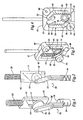
- Fig. 1 shows a lancing
device 10, in perspective view, for use with a lance (not shown). Thedevice 10 comprises aframe 12 supporting a parallelogram-shapedrack 14. Therack 14 is better seen in Fig. 2 which is a side elevation view of the lancingdevice 10. Figs. 3 and 4 show the reverse side of theframe 12 shown in Figs. 1 and 2. Apinion 16 is rotatably supported in therack 14. Rotation of thepinion 16 is coupled to movement of therack 14. A slider-crank system 18 is coupled to thepinion 16 and comprises adrive wheel 20 and drivearm 22 coupled to alance holder 24. Thedrive wheel 20 may be integral with thepinion 16. Thelance holder 24 may comprise arail 26 to interface with a slot (not shown); thelance holder 24 moves linearly in the slot in response to rotation of thepinion 16. - A
drive spring 28 applies force to theframe 12 for moving therack 14, wherein thepinion 16 is rotated counterclockwise (clockwise in Figs. 3 and 4) and the slider-crank system 18 moves thelance holder 24 from a retracted position to an extended position. Further rotation moves thelancet holder 24 from the extended position to the retracted position. It will be understood by those of ordinary skill in the art that where the lancing device is embodied in a housing, extension and retraction of the lance holder does not require the lance holder to be extended from the housing or retracted into the housing. But when the lance holder is in the retracted position a lance is typically within the housing, and when the lance holder is in the extended position, the lance is typically extended beyond the housing. - Figs. 3 and 4 show perspective and side elevation views of the frame 12 (reversed from the view shown in Figs. 1 and 2), which comprises first, second, third and
fourth rack segments second rack segments pinion 16 moves from acocked position 37 to a firedposition 39. In the illustrated embodiment, thepinion 16 is linearly fixed and theframe 12 is movable relative to thepinion 16. Accordingly, movement of thepinion 16 from the cockedposition 37 to the firedposition 39 is equivalent to moving theframe 12 from the cockedposition 37 to the firedposition 39. As theframe 12 moves from the cockedposition 37 to the firedposition 39, thepinion 16 rotates counterclockwise (clockwise in Figs. 3 and 4) along a predetermined fire path defined by the first andsecond rack segment pinion 16 is mechanically stopped at the firedposition 39, whereupon thepinion 16 is simultaneously in contact with thesecond rack segment 32 and thethird rack segment 34. The third andfourth rack segment position 39 and thecocked position 37. - The fourth and
first rack segments acute angle 40. Similarly, the second andthird rack segments acute angle 42. When thepinion 16 is located at the proximalacute angle 42, thedevice 10, and thelance holder 24 in particular, is in the firedposition 39. Likewise,pinion 16 located at distalacute angle 44 corresponds to thecocked position 37. The fire path comprises a fire-pathoblique angle 44. Similarly, the cocking path comprises a cocking-pathoblique angle 46. - The
frame 12 is moved into thecocked position 37 by any of known conventional methods, such as a pull handle, and is held in the cocked position by an arm or trigger supported by a fulcrum, for example. To reduce the chance that thepinion 16 will be jammed in the rack 14 a plurality of teeth of the rack segments are modified by widening gaps between teeth. In the illustrated embodiment shown in Fig. 4, each rack segment comprises at least two modifiedteeth - The lancing
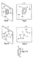
device 10 may be provided with guide means for guiding therack 14 as it moves betweencocked position 37 and firedposition 39. With reference to Figs. 1-4, the frame comprises aguide pin 60 fixed relative to the parallelogram-shapedrack 14. Theguide pin 60 interfaces aguide track 62, such as for example shown in Figs. 6 and 11A, wherein theguide pin 60 follows theguide track 62 as theframe 12 moves between positions. Asecond guide pin 64 may be fixably positioned relative to theguide pin 60, wherein the parallelogram-shapedrack 14 is positioned between theguide pin 60 and thesecond guide pin 64. Thesecond guide pin 64 similarly interfaces asecond guide track 66. The guide tracks 62 and 66 are linearly fixed relative to thepinion 16. - Figs. 5, 6 and 7 show relative positions of the
pinion 16 andpin 60 as theframe 12 moves from cockedposition 37 to firedposition 39.Pinion 16 positions are designated by circles 1-4 in Fig. 5. Fig. 6 denotes the location ofguide pin 60 relative to guidetrack 62 wherein the identified positions (1-4) correspond to the pinion positions (1-4) identified in Fig. 5. Fig. 7 denotes slider-crank positions corresponding to the pinion positions depicted in Fig. 5. Thepinion 16 is inposition 1 when theframe 12 is in thecocked position 37. As theframe 12 is released, thespring 28 drives theframe 12 downward and thepinion 16 rotates counterclockwise toposition 2, at the fire-pathoblique angle 44. As thespring 28 continues to force theframe 12 downward, thepinion 16 continues upward and to the right to position 3, at the proximalacute angle 42. Thepinion 16 is mechanically stopped by interfacing with the second andthird rack segments frame 12 is pulled into thecocked position 37, thepinion 16 continues to rotate counterclockwise, moving fromposition 3 toposition 4 and toposition 1. - For some applications, the
guide track 62 is preferably a parallelogram. Furthermore, thepin 60 may be parallelogram shaped to further stabilize theframe 12due pin 60 interfacing more completely with theguide track 62, e.g., walls of the pin slide along walls of the track, thereby allowing only relative translation while preventing rotation between thepin 60 and thetrack 62. Depending on the application, thepinion 16 rotates 180 degrees as thepinion 16 moves from the cockedposition 37 to the firedposition 39 and another 180 degrees in the same direction of rotation (counterclockwise) as thepinion 16 moves from the firedposition 39 to thecocked position 37. The pinion pitch diameter is, for some applications, approximately 0.25 inches. - Figs. 8-11A show embodiments of frame 12' and a
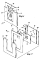
plate 70, wherein the guide means for guiding the frame 12' relative to theplate 70 comprises additional guiding means. For clarity of describing concepts of the invention, similar numbering is used to reference similar structure. Theplate 70 comprises apinion axle 72 normal to a plane parallel theplate 70, e.g., extending perpendicular from theplate 70. Thepinion 16 is rotatably supported on thepinion axle 72, whereby thepinion 16 is linearly fixed relative to theplate 70. Thepinion axle 72 comprises anenlarged hub 74. The frame 12' comprises a parallelogram shaped cut-out 76 generally conforming to the parallelogram-shapedrack 14. Theenlarged hub 74 and parallelogram-shaped cut-out 76 are adapted to interface when the frame 12' is positioned relative to theplate 70 such that thepinion 16, which is rotatably mounted on thepinion axle 72, interfaces with therack 14. Whenpinion 16 rotates along therack 14, theenlarged hub 74 moves along the cut-out 76. With addition of the pinion and rack interface, first, second and third interfaces, namely 80, 82 and 84 provide guiding means. Theinterfaces 80, 82 and 84, respectively, comprise the interfaces formed between theguide pin 60 and theguide track 62, theguide pin 64 and theguide track 66, theenlarged hub 74 and the parallelogram-shaped cut-out 76. The interfaces act to stabilize movement of the frame relative to the plate. But not all three interfaces are required to provide guide means; one is sufficient. - Figs. 12 and 13 show a lancing device 10' wherein the frame 12' is mounted for translation between
plate 70 andtop plate 86. Pullhandle 88 is used to pull the frame 12' upward and compressspring 28 untilspring guide 90 is secured byrelease arm 100.Release arm 100 is pivotally supported byfulcrum 102. Pullhandle 88 comprises protruding members (not shown) that interface withslots plate 70 to allow frame 12' to be flush mounted inpull handle 88. The pull handle 88 is flush mounted with thetop plate 86, which includesguides - From the foregoing it is apparent that a method in accordance with the invention comprises creating a laceration with a lance. One such method comprises moving a
pinion 16 along a predetermined path (30 and 32) which comprises anoblique angle 44. A lance is constrained to move in a linear motion immediately prior to reaching an extended position. Movement of thepinion 16 is coupled to alance holder 24 such that thelance holder 24 is extended when thepinion 16 reaches apredetermined position 39 on the predetermined path (30 and 32). - Linear motion of the lance as used above, refers to direction (e.g., translation) rather than velocity or acceleration of the lance. Accordingly, although the speed of the lance holder may vary over the life of the
spring 28, it is intended that thespring 28, or other conventional force means, move thelance holder 24 to a predetermined depth that does not vary over the life of the spring. Extension of thelance holder 24 beyond the predetermined depth is prevented in the illustrated embodiment because movement of thepinion 16 in further a proximal direction (upward in Figs. 2 and 5) relative to theframe 12 it prevented when thepinion 16 interfaces with the second andthird rack segment - By way of example, another method of lancing comprises moving the
pinion 16 along the predetermined path (30 and 32) and stopping movement of thepinion 16 at apredetermined position 39 on the predetermined path. Movement of a lance is coupled to movement of thepinion 16. The method further comprises preventing thelance holder 24 from extending beyond a predetermined depth, wherein thelance holder 24 is at the predetermined depth when thepinion 16 is at the predetermined position. For example, thelance holder 24 is in the extended position when thepinion 16 reaches the firedposition 39. The lance is thereby consistently extended to the same depth over the life of one or more springs. - Fig. 14 depicts an expanded perspective view of a lancing
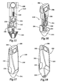
device 210 which comprises aframe 212 supporting a parallelogram-shapedrack 214.Pinion 216 is positioned to interact withrack 214 such thatframe 212 moves in a predefined path. Slider-crank system 218, comprisingdrive arm 220, couples movement ofrack 214 to alance holder 224.Lance holder 224 is moved into a cocked position by pulling onupper pull handle 288, which is affixed tolance holder 224, and lower 289 pull handled, which is snap fitted toupper pull handle 288.Drive spring 228 is thereby compressed and stores energy needed for driving therack 214 forward.Return spring 229, which is positioned in a channel in theupper pull handle 288, acts to return the pull handles to the cocked position after the handles have been pulled past the point where arack release 230locks frame 212 in the cocked position. Thus, thedrive spring 228 is maintained in a compressed state because therack release 230 prevents theframe 212 from sliding forward, until the release is triggered. By returning the pull handles 288 and 289 to their rest position with thereturn spring 229, the handles are prevented from inadvertently catching a finger or thumb when the lance is extended by driving theframe 212 forward. Another concern with allowing theframe 212 to drive the pull handles is that the puncture would may be affected by the handles slamming into the casing. - The
rack release 230 comprises anextension 232 that depresses as it slides over a conformingextension 234 integral withframe 212. The illustrated extensions are relatively small ramps. Depressingrelease button 236 disengages therack release 230 by pushing the extension (rack-release ramp) away fromframe ramp 234, thereby firing the lance.Release button 236 is returned to a set position by releasebutton foam spring 238. -
Frame 212 andlance holder 224 are operatively positioned inupper case 240 andlower case 242. The cases are snap-fitted together, or maintained together by other conventional means.End cap 244 is removable and protects a disposable lance (not shown). Theend cap 244 also helps ensure proper lancing depth. The end cap has a face perpendicular to the lancing motion. The user can thereby stabilize the lancing device by placing the end cap face flush against the skin to ensure a perpendicular lancing operation. - Fig. 15 shows a side elevation view of lancing
device 210 with upper andlower cases device 210 withoutupper case 240 andlower case 242. Fig. 17 and 18 show assembled perspective views of lancingdevice 210. - While the present invention has been described with reference to one or more particular embodiments, those skilled in the art will recognize that many changes may be made thereto without departing from the spirit and scope of the present invention. Each of these embodiments, and obvious variations thereof, is contemplated as falling within the spirit and scope of the claimed invention, which is set forth in the following claims.
Claims (37)
- A lancing device for use with a lance, the device comprising:a frame comprising a parallelogram-shape gear rack, the frame being movably supported;a pinion rotatably mounted to interface the gear rack, the pinion being rotated in response to the movement of the gear rack; anda lance holder movable between a fired position and a cocked position, wherein movement of the lance holder is in response to rotation of the pinion.
- The device of Claim 1, wherein the lance holder moves from the cocked position to the fired position as the pinion rotates 180°.
- The device of Claim 2, wherein the pinion traverses approximately one-half of the rack as the lance holder moves from the cocked position to the fired position.
- The device of Claim 1, wherein the parallelogram-shaped rack comprises a first acute angle and a second acute angle and the pinion is positioned proximate to the first acute angle when the lance holder is in the cocked position and the pinion is positioned proximate to the second acute angle when the lance holder is in the fired position.
- The device of Claim 1, wherein the pinion rotates 180° as the pinion moves from the first acute angle to the second acute angle.
- A lancing device for use with a lance, the device comprising:a plate;a pinion linearly fixed relative to the plate;a frame movable relative to the plate and comprising two rack segments positioned to form an oblique angle between the two rack segments, wherein the frame is movable between a cocked position and a fired position and the pinion is positioned to travel along the two rack segments as the frame moves from the cocked position to the fired position; anda lance holder coupled to movement of the pinion, wherein the lance holder is linearly movable from a retracted position to an extended position as the frame moves from the cocked position to the fired position.
- The device of Claim 6, comprising a spring positioned to move the frame from the cocked position to the fired position.
- The device of Claim 6, comprising a slider-crank system coupling movement of the pinion to the lance holder, wherein moving the frame moves the lance holder.
- The device of Claim 8, wherein the slider-crank system comprises a drive arm connecting the pinion and the lance holder.
- The device of Claim 9, wherein the pinion rotates 180° as the frame moves from the cocked position to the fired position.
- The device of Claim 6, comprising guide means for guiding movement of the frame relative to the plate.
- The device of Claim 6, comprising slider-crank means for coupling movement of the pinion to the lance holder, wherein moving the frame moves the lance holder.
- A lancing device for use with a lance, the device comprising:a frame;gear rack and pinion means for moving the frame along a predetermined path from a cocked position to a fired position, the gear rack and pinion means comprising one or more rack segments fixed relative to the frame, and a pinion interfacing the one or more rack segments;lance holder means for holding and moving the lance in linear motion from a retracted position to a predetermined extended position;means for coupling movement of the frame to the lance holder means such that the lance holder moves the lance from the retracted position to the extended position as the frame moves from the cocked position to the fired position along the predetermined path; andmeans for preventing the lance from extending beyond the predetermined extended position.
- The device of Claim 13, further comprising guide means for guiding the frame along the predetermined path.
- The device of Claim 13, further comprising spring means for moving the frame from the cocked position to the fired position.
- The device of Claim 15, further comprising release means for releasing the frame from the cocked position and allowing the spring means to move the frame to the fired position.
- The device of Claim 16, wherein the one or more rack segments form a parallelogram.
- The device of Claim 13, wherein the one or more rack segments form a parallelogram.
- The device of Claim 13, wherein the predetermined path along which the frame moves is non-linear.
- A method of using a lancing device, the method comprising the acts of:providing a lancing device including a parallelogram-shaped gear rack, a pinion rotatably supported in the gear rack, a slider-crank system including a drive arm coupled to the pinion, and a lance holder coupled to the drive arm;rotating the pinion in response to the movement of the gear rack; anddriving the lance holder in linear motion in response to the rotation of the pinion.
- The method of claim 20 wherein the lancing device further comprises a drive wheel coupling the drive arm to the pinion.
- The method of claim 20 wherein the parallelogram-shaped gear rack comprises a proximal acute angle, and a distal acute angle positioned closer to the lance holder than the proximal acute angle, and wherein the pinion rotates 180° when moving between the distal acute angle and the proximal acute angle.
- The method of claim 22 wherein the lance holder moves from a cocked position to a fired position and wherein the lance holder is in the cocked position when the pinion is positioned at the distal acute angle and in the fired position when the pinion is positioned at the proximal acute angle.
- The method of claim 22 wherein the lancing device further comprises a first guide pin fixed relative to the parallelogram-shaped gear rack and a first guide track linearly fixed relative to the pinion, the first guide pin interfacing with the first guide track as the parallelogram-shaped gear rack moves relative to the pinion, whereby movement of the rack is guided.
- The method of claim 24 wherein the lancing device further comprises:a second guide pin fixed relative to the parallelogram-shaped gear rack, the gear rack being positioned between the first and second guide pins; anda second guide track fixed relative to the first guide track, wherein the pinion is positioned between the first and second guide tracks and the second guide pin interfaces with the second guide track as the parallelogram-shaped gear rack moves relative to the pinion.
- The method of claim 25 wherein the first and second guide tracks are parallelogram shaped.
- The method of claim 24 wherein the first guide track is parallelogram shaped.
- The method of claim 27 wherein the first guide pin is cylindrically shaped.
- The method of claim 20 wherein the lancing device further comprises a drive spring positioned to move the lance holder.
- The method of claim 29 wherein the parallelogram-shaped gear rack is positioned between the lance holder and the drive spring.
- The method of claim 29 wherein the parallelogram-shaped gear rack comprises four segments, wherein the rotation of the pinion is between a first acute angle position and a second acute angle position, the pinion comprising pinion teeth and wherein the rack segments comprise rack teeth being adapted to engage the pinion teeth and at least two rack teeth on each segment are modified to reduce chances of the pinion jamming at either one of the first and second acute angle positions.
- The method of claim 20, wherein the pinion rotates 360° as the lance holder linearly moves from a cocked position to a fired position and back to the cocked position.
- A method of using a lancing device, the method comprising the acts of:providing a frame including a parallelogram-shaped gear rack, a pinion rotatably mounted to interface the gear rack, and a lance holder, the frame being movably supported;rotating the pinion in response to the movement of the gear rack; andmoving the lance holder between a fired position and a cocked position, wherein movement of the lance holder is in response to rotation of the pinion.
- The method of claim 33, wherein the lance holder moves from the cocked position to the fired position as the pinion rotates 180°.
- The method of claim 34 wherein the pinion traverses approximately one-half of the rack as the lance holder moves from the cocked position to the fired position.
- The method of claim 34 wherein the parallelogram-shaped rack comprises a first acute angle and a second acute angle and the pinion is positioned proximate to the first acute angle when the lance holder is in the cocked position and the pinion is positioned proximate to the second acute angle when the lance holder is in the fired position.
- The method of claim 36, wherein the pinion rotates 180° as the pinion moves from the first acute angle to the second acute angle.
Applications Claiming Priority (2)
| Application Number | Priority Date | Filing Date | Title |
|---|---|---|---|
| US41842202P | 2002-10-15 | 2002-10-15 | |
| EP03022296A EP1415593B1 (en) | 2002-10-15 | 2003-10-02 | Lancing device |
Related Parent Applications (2)
| Application Number | Title | Priority Date | Filing Date |
|---|---|---|---|
| EP03022296A Division EP1415593B1 (en) | 2002-10-15 | 2003-10-02 | Lancing device |
| EP03022296.2 Division | 2003-10-02 |
Publications (2)
| Publication Number | Publication Date |
|---|---|
| EP1847219A1 true EP1847219A1 (en) | 2007-10-24 |
| EP1847219B1 EP1847219B1 (en) | 2012-02-08 |
Family
ID=38520709
Family Applications (1)
| Application Number | Title | Priority Date | Filing Date |
|---|---|---|---|
| EP07015743A Expired - Fee Related EP1847219B1 (en) | 2002-10-15 | 2003-10-02 | Lancing device |
Country Status (1)
| Country | Link |
|---|---|
| EP (1) | EP1847219B1 (en) |
Cited By (6)
| Publication number | Priority date | Publication date | Assignee | Title |
|---|---|---|---|---|
| WO2012089521A1 (en) * | 2010-12-30 | 2012-07-05 | Roche Diagnostics Gmbh | Handheld medical diagnostic devices |
| WO2013192177A1 (en) * | 2012-06-18 | 2013-12-27 | Facet Technologies, Llc | Uni-directional drive mechanism for lancing device |
| WO2014043457A1 (en) * | 2012-09-13 | 2014-03-20 | Facet Technologies, Llc | Push-to-charge mechanism for lancing device |
| US8852123B2 (en) | 2010-12-30 | 2014-10-07 | Roche Diagnostics Operations, Inc. | Handheld medical diagnostic devices housing with sample transfer |
| US9486164B2 (en) | 2010-12-30 | 2016-11-08 | Roche Diabetes Care, Inc. | Handheld medical diagnostic device with lancet and sample transfer |
| US9717452B2 (en) | 2010-12-30 | 2017-08-01 | Roche Diabetes Care, Inc. | Handheld medical diagnostic devices with lancing speed control |
Citations (5)
| Publication number | Priority date | Publication date | Assignee | Title |
|---|---|---|---|---|
| US5304193A (en) | 1993-08-12 | 1994-04-19 | Sam Zhadanov | Blood lancing device |
| US5938679A (en) * | 1997-10-14 | 1999-08-17 | Hewlett-Packard Company | Apparatus and method for minimally invasive blood sampling |
| US5997561A (en) * | 1996-02-06 | 1999-12-07 | Roche Diagnostics Gmbh | Skin cutter for painless extraction of small blood amounts |
| US6409740B1 (en) * | 1999-10-09 | 2002-06-25 | Roche Diagnostics Gmbh | Blood lancet system for withdrawing blood for diagnostic purposes |
| EP1254632A1 (en) | 2001-05-05 | 2002-11-06 | Roche Diagnostics GmbH | Blood lancet with pivot mechanism |
-
2003
- 2003-10-02 EP EP07015743A patent/EP1847219B1/en not_active Expired - Fee Related
Patent Citations (5)
| Publication number | Priority date | Publication date | Assignee | Title |
|---|---|---|---|---|
| US5304193A (en) | 1993-08-12 | 1994-04-19 | Sam Zhadanov | Blood lancing device |
| US5997561A (en) * | 1996-02-06 | 1999-12-07 | Roche Diagnostics Gmbh | Skin cutter for painless extraction of small blood amounts |
| US5938679A (en) * | 1997-10-14 | 1999-08-17 | Hewlett-Packard Company | Apparatus and method for minimally invasive blood sampling |
| US6409740B1 (en) * | 1999-10-09 | 2002-06-25 | Roche Diagnostics Gmbh | Blood lancet system for withdrawing blood for diagnostic purposes |
| EP1254632A1 (en) | 2001-05-05 | 2002-11-06 | Roche Diagnostics GmbH | Blood lancet with pivot mechanism |
Cited By (9)
| Publication number | Priority date | Publication date | Assignee | Title |
|---|---|---|---|---|
| WO2012089521A1 (en) * | 2010-12-30 | 2012-07-05 | Roche Diagnostics Gmbh | Handheld medical diagnostic devices |
| US8852123B2 (en) | 2010-12-30 | 2014-10-07 | Roche Diagnostics Operations, Inc. | Handheld medical diagnostic devices housing with sample transfer |
| US9486164B2 (en) | 2010-12-30 | 2016-11-08 | Roche Diabetes Care, Inc. | Handheld medical diagnostic device with lancet and sample transfer |
| US9717452B2 (en) | 2010-12-30 | 2017-08-01 | Roche Diabetes Care, Inc. | Handheld medical diagnostic devices with lancing speed control |
| WO2013192177A1 (en) * | 2012-06-18 | 2013-12-27 | Facet Technologies, Llc | Uni-directional drive mechanism for lancing device |
| US9474479B2 (en) | 2012-06-18 | 2016-10-25 | Facet Technologies, Llc | Uni-directional drive mechanism for lancing device |
| WO2014043457A1 (en) * | 2012-09-13 | 2014-03-20 | Facet Technologies, Llc | Push-to-charge mechanism for lancing device |
| US9149221B2 (en) | 2012-09-13 | 2015-10-06 | Facet Technologies, Llc | Push-to-charge mechanism for lancing device |
| US10092231B2 (en) | 2012-09-13 | 2018-10-09 | Facet Technologies, Llc | Push-to-charge mechanism for lancing device |
Also Published As
| Publication number | Publication date |
|---|---|
| EP1847219B1 (en) | 2012-02-08 |
Similar Documents
| Publication | Publication Date | Title |
|---|---|---|
| US7144404B2 (en) | Lancing device | |
| EP1163879B1 (en) | Lancing mechanism | |
| EP1031319B1 (en) | Lancing device having a releasable connector | |
| EP1031318B1 (en) | Lancing device causing reduced pain | |
| US8568434B2 (en) | Lancing device | |
| US9089294B2 (en) | Analyte measurement device with a single shot actuator | |
| US7273484B2 (en) | Blood withdrawal system | |
| US4577630A (en) | Reusable breach loading target pressure activated lancet firing device | |
| US9095293B2 (en) | Lancing device and lancet | |
| EP1755454B1 (en) | Squeeze-activated medical puncturing device | |
| ES2557466T3 (en) | Removable lancet cuff for cuff device | |
| JP5876074B2 (en) | Portable medical diagnostic device with puncture speed control | |
| US20070010841A1 (en) | Lancet assembly | |
| US20060264997A1 (en) | Finger activated lancet device | |
| JP2012510851A (en) | Puncture device | |
| KR101462447B1 (en) | Safety Blood Lancet Device | |
| EP2050393B1 (en) | Lancing device | |
| EP1847219B1 (en) | Lancing device | |
| JP5027121B2 (en) | Patient skin puncture device | |
| EP2836125B1 (en) | Lancing device with side activated charge and eject mechanisms |
Legal Events
| Date | Code | Title | Description |
|---|---|---|---|
| PUAI | Public reference made under article 153(3) epc to a published international application that has entered the european phase |
Free format text: ORIGINAL CODE: 0009012 |
|
| AC | Divisional application: reference to earlier application |
Ref document number: 1415593 Country of ref document: EP Kind code of ref document: P |
|
| AK | Designated contracting states |
Kind code of ref document: A1 Designated state(s): AT BE BG CH CY CZ DE DK EE ES FI FR GB GR HU IE IT LI LU MC NL PT RO SE SI SK TR |
|
| 17P | Request for examination filed |
Effective date: 20080424 |
|
| 17Q | First examination report despatched |
Effective date: 20080520 |
|
| AKX | Designation fees paid |
Designated state(s): DE FR GB IT |
|
| REG | Reference to a national code |
Ref country code: DE Ref legal event code: R079 Ref document number: 60339983 Country of ref document: DE Free format text: PREVIOUS MAIN CLASS: A61B0005150000 Ipc: A61B0005151000 |
|
| GRAP | Despatch of communication of intention to grant a patent |
Free format text: ORIGINAL CODE: EPIDOSNIGR1 |
|
| RIC1 | Information provided on ipc code assigned before grant |
Ipc: A61B 5/151 20060101AFI20110810BHEP |
|
| GRAS | Grant fee paid |
Free format text: ORIGINAL CODE: EPIDOSNIGR3 |
|
| GRAA | (expected) grant |
Free format text: ORIGINAL CODE: 0009210 |
|
| AC | Divisional application: reference to earlier application |
Ref document number: 1415593 Country of ref document: EP Kind code of ref document: P |
|
| AK | Designated contracting states |
Kind code of ref document: B1 Designated state(s): DE FR GB IT |
|
| REG | Reference to a national code |
Ref country code: GB Ref legal event code: FG4D |
|
| REG | Reference to a national code |
Ref country code: DE Ref legal event code: R096 Ref document number: 60339983 Country of ref document: DE Effective date: 20120405 |
|
| PG25 | Lapsed in a contracting state [announced via postgrant information from national office to epo] |
Ref country code: IT Free format text: LAPSE BECAUSE OF FAILURE TO SUBMIT A TRANSLATION OF THE DESCRIPTION OR TO PAY THE FEE WITHIN THE PRESCRIBED TIME-LIMIT Effective date: 20120208 |
|
| PLBE | No opposition filed within time limit |
Free format text: ORIGINAL CODE: 0009261 |
|
| STAA | Information on the status of an ep patent application or granted ep patent |
Free format text: STATUS: NO OPPOSITION FILED WITHIN TIME LIMIT |
|
| 26N | No opposition filed |
Effective date: 20121109 |
|
| REG | Reference to a national code |
Ref country code: DE Ref legal event code: R097 Ref document number: 60339983 Country of ref document: DE Effective date: 20121109 |
|
| GBPC | Gb: european patent ceased through non-payment of renewal fee |
Effective date: 20121002 |
|
| REG | Reference to a national code |
Ref country code: FR Ref legal event code: ST Effective date: 20130628 |
|
| PG25 | Lapsed in a contracting state [announced via postgrant information from national office to epo] |
Ref country code: GB Free format text: LAPSE BECAUSE OF NON-PAYMENT OF DUE FEES Effective date: 20121002 |
|
| PG25 | Lapsed in a contracting state [announced via postgrant information from national office to epo] |
Ref country code: FR Free format text: LAPSE BECAUSE OF NON-PAYMENT OF DUE FEES Effective date: 20121031 |
|
| PGFP | Annual fee paid to national office [announced via postgrant information from national office to epo] |
Ref country code: DE Payment date: 20151028 Year of fee payment: 13 |
|
| REG | Reference to a national code |
Ref country code: DE Ref legal event code: R119 Ref document number: 60339983 Country of ref document: DE |
|
| PG25 | Lapsed in a contracting state [announced via postgrant information from national office to epo] |
Ref country code: DE Free format text: LAPSE BECAUSE OF NON-PAYMENT OF DUE FEES Effective date: 20170503 |
|
| P01 | Opt-out of the competence of the unified patent court (upc) registered |
Effective date: 20230526 |