EP1845574A1 - Fuel cell system and start method thereof - Google Patents
Fuel cell system and start method thereof Download PDFInfo
- Publication number
- EP1845574A1 EP1845574A1 EP06712082A EP06712082A EP1845574A1 EP 1845574 A1 EP1845574 A1 EP 1845574A1 EP 06712082 A EP06712082 A EP 06712082A EP 06712082 A EP06712082 A EP 06712082A EP 1845574 A1 EP1845574 A1 EP 1845574A1
- Authority
- EP
- European Patent Office
- Prior art keywords
- fuel cell
- cell system
- secondary battery
- mode
- starting
- Prior art date
- Legal status (The legal status is an assumption and is not a legal conclusion. Google has not performed a legal analysis and makes no representation as to the accuracy of the status listed.)
- Granted
Links
Images


Classifications
-
- H—ELECTRICITY
- H01—ELECTRIC ELEMENTS
- H01M—PROCESSES OR MEANS, e.g. BATTERIES, FOR THE DIRECT CONVERSION OF CHEMICAL ENERGY INTO ELECTRICAL ENERGY
- H01M16/00—Structural combinations of different types of electrochemical generators
- H01M16/003—Structural combinations of different types of electrochemical generators of fuel cells with other electrochemical devices, e.g. capacitors, electrolysers
- H01M16/006—Structural combinations of different types of electrochemical generators of fuel cells with other electrochemical devices, e.g. capacitors, electrolysers of fuel cells with rechargeable batteries
-
- H—ELECTRICITY
- H01—ELECTRIC ELEMENTS
- H01M—PROCESSES OR MEANS, e.g. BATTERIES, FOR THE DIRECT CONVERSION OF CHEMICAL ENERGY INTO ELECTRICAL ENERGY
- H01M10/00—Secondary cells; Manufacture thereof
- H01M10/42—Methods or arrangements for servicing or maintenance of secondary cells or secondary half-cells
- H01M10/48—Accumulators combined with arrangements for measuring, testing or indicating the condition of cells, e.g. the level or density of the electrolyte
-
- H—ELECTRICITY
- H01—ELECTRIC ELEMENTS
- H01M—PROCESSES OR MEANS, e.g. BATTERIES, FOR THE DIRECT CONVERSION OF CHEMICAL ENERGY INTO ELECTRICAL ENERGY
- H01M8/00—Fuel cells; Manufacture thereof
- H01M8/04—Auxiliary arrangements, e.g. for control of pressure or for circulation of fluids
- H01M8/04082—Arrangements for control of reactant parameters, e.g. pressure or concentration
- H01M8/04089—Arrangements for control of reactant parameters, e.g. pressure or concentration of gaseous reactants
-
- H—ELECTRICITY
- H01—ELECTRIC ELEMENTS
- H01M—PROCESSES OR MEANS, e.g. BATTERIES, FOR THE DIRECT CONVERSION OF CHEMICAL ENERGY INTO ELECTRICAL ENERGY
- H01M8/00—Fuel cells; Manufacture thereof
- H01M8/04—Auxiliary arrangements, e.g. for control of pressure or for circulation of fluids
- H01M8/04082—Arrangements for control of reactant parameters, e.g. pressure or concentration
- H01M8/04186—Arrangements for control of reactant parameters, e.g. pressure or concentration of liquid-charged or electrolyte-charged reactants
- H01M8/04194—Concentration measuring cells
-
- H—ELECTRICITY
- H01—ELECTRIC ELEMENTS
- H01M—PROCESSES OR MEANS, e.g. BATTERIES, FOR THE DIRECT CONVERSION OF CHEMICAL ENERGY INTO ELECTRICAL ENERGY
- H01M8/00—Fuel cells; Manufacture thereof
- H01M8/04—Auxiliary arrangements, e.g. for control of pressure or for circulation of fluids
- H01M8/04223—Auxiliary arrangements, e.g. for control of pressure or for circulation of fluids during start-up or shut-down; Depolarisation or activation, e.g. purging; Means for short-circuiting defective fuel cells
- H01M8/04225—Auxiliary arrangements, e.g. for control of pressure or for circulation of fluids during start-up or shut-down; Depolarisation or activation, e.g. purging; Means for short-circuiting defective fuel cells during start-up
-
- H—ELECTRICITY
- H01—ELECTRIC ELEMENTS
- H01M—PROCESSES OR MEANS, e.g. BATTERIES, FOR THE DIRECT CONVERSION OF CHEMICAL ENERGY INTO ELECTRICAL ENERGY
- H01M8/00—Fuel cells; Manufacture thereof
- H01M8/04—Auxiliary arrangements, e.g. for control of pressure or for circulation of fluids
- H01M8/04298—Processes for controlling fuel cells or fuel cell systems
- H01M8/043—Processes for controlling fuel cells or fuel cell systems applied during specific periods
- H01M8/04302—Processes for controlling fuel cells or fuel cell systems applied during specific periods applied during start-up
-
- H—ELECTRICITY
- H01—ELECTRIC ELEMENTS
- H01M—PROCESSES OR MEANS, e.g. BATTERIES, FOR THE DIRECT CONVERSION OF CHEMICAL ENERGY INTO ELECTRICAL ENERGY
- H01M8/00—Fuel cells; Manufacture thereof
- H01M8/04—Auxiliary arrangements, e.g. for control of pressure or for circulation of fluids
- H01M8/04298—Processes for controlling fuel cells or fuel cell systems
- H01M8/04313—Processes for controlling fuel cells or fuel cell systems characterised by the detection or assessment of variables; characterised by the detection or assessment of failure or abnormal function
- H01M8/0432—Temperature; Ambient temperature
- H01M8/04328—Temperature; Ambient temperature of anode reactants at the inlet or inside the fuel cell
-
- H—ELECTRICITY
- H01—ELECTRIC ELEMENTS
- H01M—PROCESSES OR MEANS, e.g. BATTERIES, FOR THE DIRECT CONVERSION OF CHEMICAL ENERGY INTO ELECTRICAL ENERGY
- H01M8/00—Fuel cells; Manufacture thereof
- H01M8/04—Auxiliary arrangements, e.g. for control of pressure or for circulation of fluids
- H01M8/04298—Processes for controlling fuel cells or fuel cell systems
- H01M8/04313—Processes for controlling fuel cells or fuel cell systems characterised by the detection or assessment of variables; characterised by the detection or assessment of failure or abnormal function
- H01M8/0432—Temperature; Ambient temperature
- H01M8/04365—Temperature; Ambient temperature of other components of a fuel cell or fuel cell stacks
-
- H—ELECTRICITY
- H01—ELECTRIC ELEMENTS
- H01M—PROCESSES OR MEANS, e.g. BATTERIES, FOR THE DIRECT CONVERSION OF CHEMICAL ENERGY INTO ELECTRICAL ENERGY
- H01M8/00—Fuel cells; Manufacture thereof
- H01M8/04—Auxiliary arrangements, e.g. for control of pressure or for circulation of fluids
- H01M8/04298—Processes for controlling fuel cells or fuel cell systems
- H01M8/04313—Processes for controlling fuel cells or fuel cell systems characterised by the detection or assessment of variables; characterised by the detection or assessment of failure or abnormal function
- H01M8/0444—Concentration; Density
- H01M8/04447—Concentration; Density of anode reactants at the inlet or inside the fuel cell
-
- H—ELECTRICITY
- H01—ELECTRIC ELEMENTS
- H01M—PROCESSES OR MEANS, e.g. BATTERIES, FOR THE DIRECT CONVERSION OF CHEMICAL ENERGY INTO ELECTRICAL ENERGY
- H01M8/00—Fuel cells; Manufacture thereof
- H01M8/04—Auxiliary arrangements, e.g. for control of pressure or for circulation of fluids
- H01M8/04298—Processes for controlling fuel cells or fuel cell systems
- H01M8/04313—Processes for controlling fuel cells or fuel cell systems characterised by the detection or assessment of variables; characterised by the detection or assessment of failure or abnormal function
- H01M8/04537—Electric variables
- H01M8/04544—Voltage
- H01M8/04559—Voltage of fuel cell stacks
-
- H—ELECTRICITY
- H01—ELECTRIC ELEMENTS
- H01M—PROCESSES OR MEANS, e.g. BATTERIES, FOR THE DIRECT CONVERSION OF CHEMICAL ENERGY INTO ELECTRICAL ENERGY
- H01M8/00—Fuel cells; Manufacture thereof
- H01M8/04—Auxiliary arrangements, e.g. for control of pressure or for circulation of fluids
- H01M8/04298—Processes for controlling fuel cells or fuel cell systems
- H01M8/04313—Processes for controlling fuel cells or fuel cell systems characterised by the detection or assessment of variables; characterised by the detection or assessment of failure or abnormal function
- H01M8/04537—Electric variables
- H01M8/04574—Current
- H01M8/04589—Current of fuel cell stacks
-
- H—ELECTRICITY
- H01—ELECTRIC ELEMENTS
- H01M—PROCESSES OR MEANS, e.g. BATTERIES, FOR THE DIRECT CONVERSION OF CHEMICAL ENERGY INTO ELECTRICAL ENERGY
- H01M8/00—Fuel cells; Manufacture thereof
- H01M8/04—Auxiliary arrangements, e.g. for control of pressure or for circulation of fluids
- H01M8/04298—Processes for controlling fuel cells or fuel cell systems
- H01M8/04694—Processes for controlling fuel cells or fuel cell systems characterised by variables to be controlled
- H01M8/04701—Temperature
- H01M8/04708—Temperature of fuel cell reactants
-
- H—ELECTRICITY
- H01—ELECTRIC ELEMENTS
- H01M—PROCESSES OR MEANS, e.g. BATTERIES, FOR THE DIRECT CONVERSION OF CHEMICAL ENERGY INTO ELECTRICAL ENERGY
- H01M8/00—Fuel cells; Manufacture thereof
- H01M8/04—Auxiliary arrangements, e.g. for control of pressure or for circulation of fluids
- H01M8/04298—Processes for controlling fuel cells or fuel cell systems
- H01M8/04694—Processes for controlling fuel cells or fuel cell systems characterised by variables to be controlled
- H01M8/04701—Temperature
- H01M8/04716—Temperature of fuel cell exhausts
-
- H—ELECTRICITY
- H01—ELECTRIC ELEMENTS
- H01M—PROCESSES OR MEANS, e.g. BATTERIES, FOR THE DIRECT CONVERSION OF CHEMICAL ENERGY INTO ELECTRICAL ENERGY
- H01M8/00—Fuel cells; Manufacture thereof
- H01M8/04—Auxiliary arrangements, e.g. for control of pressure or for circulation of fluids
- H01M8/04298—Processes for controlling fuel cells or fuel cell systems
- H01M8/04694—Processes for controlling fuel cells or fuel cell systems characterised by variables to be controlled
- H01M8/04746—Pressure; Flow
- H01M8/04753—Pressure; Flow of fuel cell reactants
-
- H—ELECTRICITY
- H01—ELECTRIC ELEMENTS
- H01M—PROCESSES OR MEANS, e.g. BATTERIES, FOR THE DIRECT CONVERSION OF CHEMICAL ENERGY INTO ELECTRICAL ENERGY
- H01M8/00—Fuel cells; Manufacture thereof
- H01M8/04—Auxiliary arrangements, e.g. for control of pressure or for circulation of fluids
- H01M8/04298—Processes for controlling fuel cells or fuel cell systems
- H01M8/04694—Processes for controlling fuel cells or fuel cell systems characterised by variables to be controlled
- H01M8/04858—Electric variables
- H01M8/04865—Voltage
- H01M8/0488—Voltage of fuel cell stacks
-
- H—ELECTRICITY
- H01—ELECTRIC ELEMENTS
- H01M—PROCESSES OR MEANS, e.g. BATTERIES, FOR THE DIRECT CONVERSION OF CHEMICAL ENERGY INTO ELECTRICAL ENERGY
- H01M8/00—Fuel cells; Manufacture thereof
- H01M8/04—Auxiliary arrangements, e.g. for control of pressure or for circulation of fluids
- H01M8/04298—Processes for controlling fuel cells or fuel cell systems
- H01M8/04694—Processes for controlling fuel cells or fuel cell systems characterised by variables to be controlled
- H01M8/04858—Electric variables
- H01M8/04925—Power, energy, capacity or load
- H01M8/0494—Power, energy, capacity or load of fuel cell stacks
-
- H—ELECTRICITY
- H01—ELECTRIC ELEMENTS
- H01M—PROCESSES OR MEANS, e.g. BATTERIES, FOR THE DIRECT CONVERSION OF CHEMICAL ENERGY INTO ELECTRICAL ENERGY
- H01M8/00—Fuel cells; Manufacture thereof
- H01M8/04—Auxiliary arrangements, e.g. for control of pressure or for circulation of fluids
- H01M8/04298—Processes for controlling fuel cells or fuel cell systems
- H01M8/04694—Processes for controlling fuel cells or fuel cell systems characterised by variables to be controlled
- H01M8/04858—Electric variables
- H01M8/04925—Power, energy, capacity or load
- H01M8/04947—Power, energy, capacity or load of auxiliary devices, e.g. batteries, capacitors
-
- B—PERFORMING OPERATIONS; TRANSPORTING
- B60—VEHICLES IN GENERAL
- B60L—PROPULSION OF ELECTRICALLY-PROPELLED VEHICLES; SUPPLYING ELECTRIC POWER FOR AUXILIARY EQUIPMENT OF ELECTRICALLY-PROPELLED VEHICLES; ELECTRODYNAMIC BRAKE SYSTEMS FOR VEHICLES IN GENERAL; MAGNETIC SUSPENSION OR LEVITATION FOR VEHICLES; MONITORING OPERATING VARIABLES OF ELECTRICALLY-PROPELLED VEHICLES; ELECTRIC SAFETY DEVICES FOR ELECTRICALLY-PROPELLED VEHICLES
- B60L58/00—Methods or circuit arrangements for monitoring or controlling batteries or fuel cells, specially adapted for electric vehicles
- B60L58/30—Methods or circuit arrangements for monitoring or controlling batteries or fuel cells, specially adapted for electric vehicles for monitoring or controlling fuel cells
- B60L58/31—Methods or circuit arrangements for monitoring or controlling batteries or fuel cells, specially adapted for electric vehicles for monitoring or controlling fuel cells for starting of fuel cells
-
- H—ELECTRICITY
- H01—ELECTRIC ELEMENTS
- H01M—PROCESSES OR MEANS, e.g. BATTERIES, FOR THE DIRECT CONVERSION OF CHEMICAL ENERGY INTO ELECTRICAL ENERGY
- H01M2250/00—Fuel cells for particular applications; Specific features of fuel cell system
- H01M2250/20—Fuel cells in motive systems, e.g. vehicle, ship, plane
-
- H—ELECTRICITY
- H01—ELECTRIC ELEMENTS
- H01M—PROCESSES OR MEANS, e.g. BATTERIES, FOR THE DIRECT CONVERSION OF CHEMICAL ENERGY INTO ELECTRICAL ENERGY
- H01M8/00—Fuel cells; Manufacture thereof
- H01M8/04—Auxiliary arrangements, e.g. for control of pressure or for circulation of fluids
- H01M8/04082—Arrangements for control of reactant parameters, e.g. pressure or concentration
- H01M8/04089—Arrangements for control of reactant parameters, e.g. pressure or concentration of gaseous reactants
- H01M8/04119—Arrangements for control of reactant parameters, e.g. pressure or concentration of gaseous reactants with simultaneous supply or evacuation of electrolyte; Humidifying or dehumidifying
- H01M8/04156—Arrangements for control of reactant parameters, e.g. pressure or concentration of gaseous reactants with simultaneous supply or evacuation of electrolyte; Humidifying or dehumidifying with product water removal
- H01M8/04164—Arrangements for control of reactant parameters, e.g. pressure or concentration of gaseous reactants with simultaneous supply or evacuation of electrolyte; Humidifying or dehumidifying with product water removal by condensers, gas-liquid separators or filters
-
- H—ELECTRICITY
- H01—ELECTRIC ELEMENTS
- H01M—PROCESSES OR MEANS, e.g. BATTERIES, FOR THE DIRECT CONVERSION OF CHEMICAL ENERGY INTO ELECTRICAL ENERGY
- H01M8/00—Fuel cells; Manufacture thereof
- H01M8/04—Auxiliary arrangements, e.g. for control of pressure or for circulation of fluids
- H01M8/04082—Arrangements for control of reactant parameters, e.g. pressure or concentration
- H01M8/04201—Reactant storage and supply, e.g. means for feeding, pipes
- H01M8/04216—Reactant storage and supply, e.g. means for feeding, pipes characterised by the choice for a specific material, e.g. carbon, hydride, absorbent
-
- H—ELECTRICITY
- H01—ELECTRIC ELEMENTS
- H01M—PROCESSES OR MEANS, e.g. BATTERIES, FOR THE DIRECT CONVERSION OF CHEMICAL ENERGY INTO ELECTRICAL ENERGY
- H01M8/00—Fuel cells; Manufacture thereof
- H01M8/06—Combination of fuel cells with means for production of reactants or for treatment of residues
- H01M8/0662—Treatment of gaseous reactants or gaseous residues, e.g. cleaning
-
- H—ELECTRICITY
- H01—ELECTRIC ELEMENTS
- H01M—PROCESSES OR MEANS, e.g. BATTERIES, FOR THE DIRECT CONVERSION OF CHEMICAL ENERGY INTO ELECTRICAL ENERGY
- H01M8/00—Fuel cells; Manufacture thereof
- H01M8/10—Fuel cells with solid electrolytes
- H01M8/1009—Fuel cells with solid electrolytes with one of the reactants being liquid, solid or liquid-charged
- H01M8/1011—Direct alcohol fuel cells [DAFC], e.g. direct methanol fuel cells [DMFC]
-
- Y—GENERAL TAGGING OF NEW TECHNOLOGICAL DEVELOPMENTS; GENERAL TAGGING OF CROSS-SECTIONAL TECHNOLOGIES SPANNING OVER SEVERAL SECTIONS OF THE IPC; TECHNICAL SUBJECTS COVERED BY FORMER USPC CROSS-REFERENCE ART COLLECTIONS [XRACs] AND DIGESTS
- Y02—TECHNOLOGIES OR APPLICATIONS FOR MITIGATION OR ADAPTATION AGAINST CLIMATE CHANGE
- Y02E—REDUCTION OF GREENHOUSE GAS [GHG] EMISSIONS, RELATED TO ENERGY GENERATION, TRANSMISSION OR DISTRIBUTION
- Y02E60/00—Enabling technologies; Technologies with a potential or indirect contribution to GHG emissions mitigation
- Y02E60/10—Energy storage using batteries
-
- Y—GENERAL TAGGING OF NEW TECHNOLOGICAL DEVELOPMENTS; GENERAL TAGGING OF CROSS-SECTIONAL TECHNOLOGIES SPANNING OVER SEVERAL SECTIONS OF THE IPC; TECHNICAL SUBJECTS COVERED BY FORMER USPC CROSS-REFERENCE ART COLLECTIONS [XRACs] AND DIGESTS
- Y02—TECHNOLOGIES OR APPLICATIONS FOR MITIGATION OR ADAPTATION AGAINST CLIMATE CHANGE
- Y02E—REDUCTION OF GREENHOUSE GAS [GHG] EMISSIONS, RELATED TO ENERGY GENERATION, TRANSMISSION OR DISTRIBUTION
- Y02E60/00—Enabling technologies; Technologies with a potential or indirect contribution to GHG emissions mitigation
- Y02E60/30—Hydrogen technology
- Y02E60/50—Fuel cells
-
- Y—GENERAL TAGGING OF NEW TECHNOLOGICAL DEVELOPMENTS; GENERAL TAGGING OF CROSS-SECTIONAL TECHNOLOGIES SPANNING OVER SEVERAL SECTIONS OF THE IPC; TECHNICAL SUBJECTS COVERED BY FORMER USPC CROSS-REFERENCE ART COLLECTIONS [XRACs] AND DIGESTS
- Y02—TECHNOLOGIES OR APPLICATIONS FOR MITIGATION OR ADAPTATION AGAINST CLIMATE CHANGE
- Y02T—CLIMATE CHANGE MITIGATION TECHNOLOGIES RELATED TO TRANSPORTATION
- Y02T90/00—Enabling technologies or technologies with a potential or indirect contribution to GHG emissions mitigation
- Y02T90/40—Application of hydrogen technology to transportation, e.g. using fuel cells
Definitions
- the present invention relates to fuel cell systems and driving methods therefor, and more specifically, to a fuel cell system including a secondary battery which is electrically connected with a fuel cell, and a method of starting the system.
- Fuel cells take time until they attain a temperature appropriate for power generation, after being started at an ambient temperature. While the temperature is low, the fuel cells' power generation output is low. When starting, therefore, fuel cell systems obtain energy from other power supplying means than the fuel cell in order to drive their system components, etc. Fuel cell systems cannot start themselves without an energy supplier other than the fuel cell. Further, even if a fuel cell system has an energy supplier such as a secondary battery, a problem will be encountered during a start-up of the fuel cell system if there is not sufficient supply of energy from the secondary battery until the fuel cell has attained a temperature appropriate for sufficient power generation.
- Patent Document 1 A fuel cell system which includes a secondary battery is disclosed in Patent Document 1 for example.
- Patent Document 1 discloses a technique for supplying a load with electric power from a secondary battery when the system is started, during which warming-up state of the fuel cell is monitored. When it is determined that the fuel cell is warmed up to a sufficient level, the fuel cell is connected with the load so that the fuel cell supplies electric power to the load.
- Patent Document 1 JP-A 9-231991
- the fuel cell system according to Patent Document 1 does not monitor the amount of energy stored in the secondary battery, and therefore can fail to start the fuel cell system if sufficient power is not stored in the secondary battery.
- a primary object of the present invention is to provide a fuel cell system and a starting method therefor, capable of setting a start mode appropriate to the energy stored in the secondary battery so as to prevent a trouble when the system is started.
- a fuel cell system connected with a load.
- the fuel cell system includes: a fuel cell; a secondary battery electrically connected with the fuel cell; means for obtaining data concerning electric energy stored in the secondary battery; and first determination means for determining one from a plurality of start-up modes differing from each other in energy consumption, for the fuel cell system based on the obtained data concerning electric energy stored in the secondary battery.
- a method of starting a fuel cell system connected with a load includes a fuel cell and a secondary battery electrically connected with the fuel cell.
- the method includes a sequence of: obtaining data concerning electric energy stored in the secondary battery; determining one from a plurality of start-up modes differing from each other in energy consumption, for the fuel cell system based on the obtained data concerning electric energy stored in the secondary battery; and operating the fuel cell system in accordance with the determined mode.
- a start-up mode of a fuel cell system is determined based on data concerning electric energy stored in the secondary battery, and the fuel cell system is operated in accordance with the determined start-up mode. This makes it possible to select a start-up mode which is appropriate to the electric energy stored in the secondary battery, and eliminate a trouble in starting the fuel cell system.
- the start-up mode of the fuel cell system is determined based on the data concerning electric energy stored in the secondary battery and at least one threshold value for determining the start-up mode of the fuel cell system. In this case, it is possible to select an optimum start-up mode for the fuel cell system.
- the threshold value includes a first threshold value representing the energy necessary for starting the fuel cell system. Whether or not to start the fuel cell system is determined, based on the data concerning electric energy stored in the secondary battery and the first threshold value. For example, in a case where the data concerning stored electric energy refers to the stored electric energy itself, and the first threshold value represents the very energy necessary for starting the fuel cell system, the fuel cell system is started if the electric energy stored in the secondary battery is not smaller than the first threshold value. On the other hand, if the electric energy stored in the secondary battery is smaller than the first threshold value, starting of the fuel cell system is stopped, based on a judgment that it is impossible to start the fuel cell system. This makes it possible to avoid unnecessary consumption of energy.
- the threshold value includes a second threshold value representing normal-consumption energy necessary for starting the fuel cell system in a normal mode.
- the second threshold value represents the normal-consumption energy itself which is necessary for starting the fuel cell system in the normal mode
- the fuel cell system is started in the normal mode if the electric energy stored in the secondary battery is not smaller than the second threshold value.
- the fuel cell system is started in the low consumption mode. In this way, the fuel cell system is started in a mode which is appropriate to the electric energy stored in the secondary battery.
- a third threshold value which represents a sum of the normal-consumption energy necessary for starting the fuel cell system in the normal mode and a load energy demand necessary for driving the load normally is further used.
- whether or not to drive the load normally is determined, based on the data concerning electric energy stored in the secondary battery and the third threshold value.
- the load is driven normally or in a mode other than normal driving in accordance with a result of the determination.
- the third threshold value represents the very sum of the normal-consumption energy and the load energy demand
- the load is enabled for normal driving if the electric energy stored in the secondary battery is not lower than the third threshold value.
- the load is enabled for a mode other than normal driving; or more specifically, the load is enabled for a mode where energy consumable by the load is limited, and the load can be driven under a restrictive condition. As described, the load is enabled for driving within a range allowable by the electric energy stored in the secondary battery.
- a predetermined voltage for determining on whether or not the fuel cell is disconnected from the secondary battery is set to a lower value than when started in the normal mode. The determination on whether or not the fuel cell is disconnected from the secondary battery is based on the fuel cell' s output voltage and the predetermined voltage.
- the predetermined voltage is set to a lower value than when started in the normal mode, whereby the connection between the fuel cell and the secondary battery is not cut off (the connection is maintained) and charging to the seconding battery is continued in the low consumption mode, even in a case where the output voltage of the fuel cell has reached a value (which is smaller than the predetermined voltage of the normal mode) at which the connection between the fuel cell and the secondary battery would be cut off in the normal mode.
- This makes it possible to reduce discharge from the secondary battery, i.e. to cut down on a decrease in the stored electric energy.
- This arrangement provides a particular advantage when the fuel cell system is started in an environment where the fuel cell's temperature is low and therefore the fuel cell's output voltage is likely to be low.
- the invention makes use of an aqueous solution tank which stores aqueous fuel solution to be supplied to the fuel cell, an amount of aqueous solution in the aqueous solution tank is not controlled when the fuel cell system is started in the low consumption mode. In this case, there is no need for driving a pump for example, which makes it possible to reduce power consumption.
- the fuel cell when the fuel cell system is started in the low consumption mode, the fuel cell is supplied with aqueous fuel solution which has a higher concentration than a concentration used when the system is started in the normal mode, to start power generation.
- the fuel cell's temperature rises quickly, making possible to shorten the necessary time to attain the target temperature, although efficiency is decreased because of increased crossover.
- no control is performed for decreasing the amount of aqueous solution in the aqueous solution tank when the fuel cell system is started in the low consumption mode.
- the invention makes use of an air pump which supplies the fuel cell with air containing oxygen.
- the air pump When the fuel cell system is started in the low consumption mode, the air pump is operated at a lower output than when started in a normal mode, to start power generation. In this case, it is possible to reduce power consumption by the air pump.
- the invention makes use of an air pump which supplies the fuel cell with air containing oxygen, and an aqueous solution pump which supplies the fuel cell with aqueous fuel solution.
- an air pump which supplies the fuel cell with air containing oxygen
- an aqueous solution pump which supplies the fuel cell with aqueous fuel solution.
- the fuel cell system when starting the fuel cell system in the low consumption mode, the fuel cell system is connected with the load when the fuel cell' s output voltage is not lower than a voltage in the secondary battery.
- a predetermined temperature a temperature serving as a threshold to terminate no-load operation in the normal mode. This makes it possible to shorten the time for the no-load operation and the time to attain the target temperature.
- the fuel cell when the fuel cell system is started in the low consumption mode, the fuel cell is operated at a lower output voltage than when started in a normal mode at the same temperature of the fuel cell. This makes it possible to increase an output current from the fuel cell and to charge the secondary battery quickly.
- the load is switched to normal driving when electric energy stored in the secondary battery is not lower than energy represented by the third threshold value.
- This arrangement makes it possible to drive the load in a mode appropriate to the amount of charge in the secondary battery.
- the present invention can be used suitably in those fuel cell systems where the fuel cell is supplied with aqueous fuel solution for power generation.
- the present invention can be used suitably in transportation equipment which requires that, if the fuel cell system is to be mounted, the capacity of the secondary battery be small.
- the present invention can be used suitably in cases where at least one of the loads is a motor of the transportation equipment.
- data concerning stored electric energy is not limited to the stored electric energy itself, but may mean a value which has a one-to-one relationship with the stored electric energy (e.g. a value convertible to and from the amount of stored electric energy) such as the amount of electric charge, voltage, current, etc.
- energy necessary for starting the fuel cell system means energy necessary for a fuel cell system to start and attain a temperature (target temperature) at which the fuel cell can sufficiently perform power generation.
- threshold value corresponding to the energy is not limited to energy itself, but may mean a value which has a one-to-one relationship with the energy (e.g. a value convertible to and from the energy) such as the amount of electric charge, voltage, current, etc.
- normal mode is a mode of operating a fuel cell system, where no restriction is placed on operations of system components, etc. when the fuel cell system is started.
- low consumption mode is a mode of operating a fuel cell system, where restrictions are placed on operations of system components, etc. when the fuel cell system is started. Energy consumption is smaller than in the normal mode.
- load energy demand is energy necessary for driving the load normally until a fuel cell attains a temperature (target temperature) at which the fuel cell can sufficiently perform power generation.
- Normal drive or to drive normally
- a fuel cell system 10 as an embodiment of the present invention is provided as a direct methanol fuel cell system. Since direct methanol fuel cell systems do not need a reformer, the systems are used suitably for equipment which requires portability, and equipment in which size reduction is desirable.
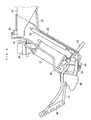
- description will be made for a case where the fuel cell system 10 is used in a motorbike taken as an example of transportation equipment. It should be noted here that the motorbike will be shown only as a motorbike frame 200 as in Fig. 2. In Fig. 2, the left side is the front side of the vehicle and the right side is the rear side thereof.
- the fuel cell system 10 is disposed along the motorbike frame 200.
- the motorbike may be referred to as a vehicle as necessary.
- the fuel cell system 10 includes a fuel cell 12.
- the fuel cell 12 is configured as a fuel cell stack constituted by a plurality of fuel cells connected (layered) in series.
- Each fuel cell includes electrolyte 12a provided by a solid polymer film, as well as an anode (fuel electrode) 12b and a cathode (air electrode) 12c which sandwich the electrolyte 12a.
- the fuel cell system 10 includes a fuel tank 14 which stores highly concentrated methanol fuel (aqueous methanol solution containing methanol at approximately 50 wt%) F.
- the fuel tank 14 is connected with an aqueous solution tank 18 which stores aqueous methanol solution S, via a fuel supply pipe 16.
- the fuel supply pipe 16 is provided with a fuel pump 20, and as the fuel pump 20 is driven, methanol fuel F in the fuel tank 14 is supplied to the aqueous solution tank 18.
- the fuel tank 14 is provided with a level sensor 15 for detecting a height of liquid surface of the methanol fuel F in the fuel tank 14.
- the aqueous solution tank 18 is provided with a level sensor 22 for detecting a height of liquid surface of the aqueous methanol solution S in the aqueous solution tank 18.
- the aqueous solution tank 18 is connected with the anode 12b of the fuel cell 12 via an aqueous solution pipe 24.
- the aqueous solution pipe 24 is provided with an aqueous solution pump 26, a radiator 28 which functions as a heat exchanger, and an aqueous solution filter 30, in this order from the upstream side.
- a cooling fan 32 is disposed near the radiator 28 in order to cool the radiator 28.
- Aqueous methanol solution S in the aqueous solution tank 18 is pumped toward the anode 12b by the aqueous solution pump 26, cooled by the radiator 28 as necessary, and further, purified by the aqueous solution filter 30 and then supplied to the anode 12b.
- the cathode 12c in the fuel cell 12 is connected with an air pump 34 via an air-side pipe 36.
- the air-side pipe 36 is provided with an air filter 38. Therefore, air from the air pump 34 which contains oxygen (oxidizer) is supplied to the cathode 12c after it is purified by the air filter 38.
- anode 12b and the aqueous solution tank 18 are connected with each other via a pipe 40, through which the aqueous solution tank 18 receives unused aqueous methanol solution and produced carbon dioxide discharged from the anode 12b.
- the cathode 12c is connected with a water tank 44 via a pipe 42.
- the pipe 42 is provided with a radiator 46 which functions as a gas-liquid separator, and near the radiator 46 a cooling fan 48 for cooling the radiator 46 is disposed.
- the cathode 12c discharges an exhaust which contains moisture (water and water vapor). The exhaust is supplied to the water tank 44 via the pipe 42.
- the aqueous solution tank 18 and the water tank 44 are connected with each other via a CO 2 vent pipe 50.
- the CO 2 vent pipe 50 is provided with a methanol trap 52 for separating aqueous methanol solution S. With this arrangement, carbon dioxide discharged from the aqueous solution tank 18 is supplied to the water tank 44.
- the water tank 44 is provided with a level sensor 54 for detecting a height of liquid in the water tank 44. Also, an exhaust gas pipe 56 is attached to the water tank 44. Through the exhaust gas pipe 56, carbon dioxide and exhaust from the cathode 12c are discharged.
- the water tank 44 is connected with the aqueous solution tank 18 via a water returning pipe 58.
- the water returning pipe 58 is provided with a water pump 60. Water in the water tank 44 is returned to the aqueous solution tank 18 by driving the water pump 60, as necessary, depending on the situation in the aqueous solution tank 18.
- a bypass pipe 62 is provided between the radiator 28 and the aqueous solution filter 30.
- the bypass pipe 62 is provided with a concentration sensor 64 for detecting the concentration of aqueous methanol solution S, and an aqueous solution temperature sensor 65 for detecting the temperature of aqueous methanol solution S.
- the fuel cell 12 is provided with a cell temperature sensor 66 for detecting the temperature of fuel cell 12, and an ambient temperature sensor 68 for detecting the ambient temperature is provided near the air pump 34. It should be noted here that the cell temperature sensor 66 is disposed at a place in the fuel cell 12 where the highest temperature will be observed, e. g. near an outlet of the aqueous methanol solution S.
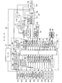
- the fuel cell system 10 includes a control circuit 70.
- the control circuit 70 includes: a CPU 72 for performing necessary calculations and providing control over operations of the fuel cell system 10; a clock circuit 74 which provides the CPU 72 with clock signals; a volatile memory 76 provided by e.g. a DRAM for keeping elapsed time based on the clock signals provided to the CPU 72, flags, calculation data, etc; a non-volatile memory 78 provided by e.g.
- the fuel cell system 10 is configured as a series type system which supplies a load with electric power via a secondary battery 108 (to be described later).
- the voltage detection circuit 84, the current detection circuit 86, the voltage adjustment circuit 88 and the diode 94 constitute a voltage control unit 100.
- the CPU 72 of the control circuit 70 as described above is supplied with detection signals from the concentration sensor 64, the aqueous solution temperature sensor 65, the cell temperature sensor 66 and the ambient temperature sensor 68, via the interface circuits 82a, 82b, 82c and 82d respectively.
- the CPU 72 is supplied with detection signals from the level sensors 15, 22 and 54 via the interface circuits 821, 82k and 82o respectively.
- the CPU 72 is supplied with detection signals from a rollover switch 102 which detects rollover, via the interface circuit 82n, as well as signals from an input section 104 which is used for making various settings and information entry, via the interface circuit 82p.
- the CPU 72 sends control signals to the fuel pump 20, the aqueous solution pump 26, the air pump 34, the heat-exchanger cooling fan 32, the gas-liquid separator cooling fan 48 and the water pump 60 via the interface circuits 82j, 82g, 82h, 82f, 82e and 82i respectively; hence the CPU 72 controls these system components. Also, the CPU 72 sends control signals to a display unit 106 via the interface circuit 82q, and controls the display unit 106 which is a unit for displaying a variety of information and providing the rider of the motorbike with a variety of information.
- the fuel cell 12 is connected with the secondary battery 108 placed in a battery box 107.
- the secondary battery 108 complements the output from the fuel cell 12, is charged with electric energy from the fuel cell 12, and discharges the electric energy to supply power to a motor 116 (to be described later) and system components. Particularly, when starting power generation, system components are driven by electric energy from the secondary battery 108, and as the amount of power generated by the fuel cell 12 increases, the electric energy is stored in the secondary battery 108.
- the secondary battery 108 is provided by a nickel hydride battery, a lithium ion battery, a Ni-Cd battery, etc.
- the secondary battery 108 is connected with a control device 110.
- the control device 110 is constituted by a CPU, a memory, etc., and includes a secondary-battery charge-amount detection unit 112 which detects an amount of charge in the secondary battery 108, and can also detect a voltage, current, temperature, etc. of the secondary battery 108.
- the amount of charge in the secondary battery 108 is obtained by multiplying the voltage of the secondary battery with a predetermined constant; however, the calculation may also include factors which reflect consideration into the electric current and the extent of battery deterioration.
- the control device 110 sends these pieces of information about the secondary battery 108 to the control circuit 70 via an interface circuit 113, and also to a motor controller 114 connected with the secondary battery 108.
- the motor controller 114 is connected to a load, i.e.
- a motor 116 of the motorbike and the electric energy supplied to the motor 116 is controlled by the motor controller 114.
- the motor controller 114 is connected with a meter 118 for measuring various data of the motor 116. Information such as data measured by the meter 118, state of the motor 116, etc. is inputted to the CPU 72 via the interface circuit 113 of the control device 110 and the interface circuit 82m of the control circuit 70.
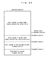
- the volatile memory 76 stores such data as: the amount of charge in the secondary battery 108; electric energy stored in the secondary battery 108; detected temperatures of the fuel cell 12; a necessary time for the fuel cell 12 to attain a target temperature; a first threshold value for determining on whether or not the fuel cell system 10 should be started; a second threshold value for determining on whether the fuel cell system 10 should be started in normal mode or in low consumption mode; a third threshold value for determining on whether or not the load may be driven normally; a load energy demand; etc.
- the non-volatile memory 78 stores such data as: low-consumption electric power necessary for driving the fuel cell system 10 in low consumption mode for a unit of time; normal electric power necessary for driving the fuel cell system 10 in normal mode for a unit of time, a predetermined voltage for determining whether or not the fuel cell 12 should be brought to a no-load state; a vehicle average output which represents a specific unit of energy necessary for driving the load normally for a unit of time, etc.
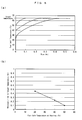
- the non-volatile memory 78 also stores table data which indicates a relationship between the temperature of the fuel cell 12 when starting the fuel cell system 10 and a necessary time for attaining a target temperature (approximately 65°C in the present embodiment).
- the necessary time is calculated on the basis of the temperature of the fuel cell 12 at the time of start-up, power generation efficiency and thermal capacity. For example, as shown in Figs. 5(a) and (b), the higher the temperature of the fuel cell 12 at the time of system start-up, the shorter will be the necessary time to the target temperature.
- a necessary time for the fuel cell 12 to attain the target temperature is estimated by making reference to the table data.
- fuel cell temperatures at the time point zero each indicate the temperature at the time of start-up.
- the non-volatile memory 78 also stores control information (control parameters, programs, etc.) for a plurality of start-up modes of different energy consumption.
- the CPU 72 defines the first determination means and the second determination means, whereas the volatile memory 76 and the non-volatile memory 78 define the memory means.
- the current detection circuit 86 detects an output current from the fuel cell 12. The current detected by the current detection circuit 86 is converted into a voltage and is supplied to the CPU 72.
- the current detection circuit 86 is connected, on its output side, with a voltage detection circuit 84 which detects an output voltage of the fuel cell 12. The detected output voltage of the fuel cell 12 is supplied to the CPU 72.
- the voltage detection circuit 84 also detects a voltage of the secondary battery 108. Further, the voltage detection circuit 84 is provided, on its output side, with a voltage adjustment circuit 88 which includes an FET1 and an FET2.
- the CPU 72 supplies control signals to the gate in each of the FET1 and the FET2, and the output voltage of the fuel cell 12 is adjusted on the basis of the control signals. Further, the voltage adjustment circuit 88 is connected, on its output side, with the diode 94 for protecting the fuel cell 12.
- the voltage control unit 100 which has the configuration as described is connected, on its output side, with the secondary-battery charge-amount detection unit 112.
- the secondary-battery charge-amount detection unit 112 detects the amount of charge in the secondary battery 108.
- a power generation operation by the fuel cell system 10 as the above will be outlined.
- the fuel cell system 10 drives its system components such as the aqueous solution pump 26 and the air pump 34, thereby starting the power generation (operation).
- the aqueous solution pump 26 When starting the power generation, the aqueous solution pump 26 is driven, whereby aqueous methanol solution S of a desired concentration stored in the aqueous solution tank 18 is pumped toward the fuel cell 12, cooled by the radiator 28 as necessary, purified by the aqueous solution filter 30, and then supplied to the anode 12b.
- air which contains oxygen serving as an oxidizer is pumped by the air pump 34 toward the fuel cell 12, purified by the air filter 38, and then supplied to the cathode 12c.
- methanol and water in the aqueous methanol solution S react electrochemically with each other to produce carbon dioxide and hydrogen ions.
- the produced hydrogen ions flow through the electrolyte 12a, to the cathode 12c.
- the hydrogen ions react electrochemically with oxygen in the air supplied to the cathode 12c, to produce water (water vapor) and electric energy.
- Carbon dioxide produced at the anode 12b in the fuel cell 12 flows through the pipe 40, the aqueous solution tank 18 and the CO 2 vent pipe 50, to the water tank 44, and then discharged from the exhaust gas pipe 56.
- water crossover is a phenomenon in which a few mols of water moves to the cathode 12c, accompanying the hydrogen ions which are produced at the anode 12b and are moving to the cathode 12c.
- Methanol crossover is a phenomenon in which methanol moves to the cathode 12c, accompanying the hydrogen ions which move to the cathode 12c.
- methanol reacts with air supplied from the air pump 34, and thereby decomposes into water and carbon dioxide.
- Water (liquid) which was collected in the water tank 44 is returned as appropriately by the water pump 60, through the water returning pipe 58, to the aqueous solution tank 18, where the water is used for the methanol aqueous solution S.
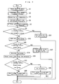
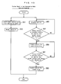
- the fuel cell system 10 has three start-up modes, a normal mode, a low consumption mode and no start-up. Energy consumed in each mode is different.
- Step S1 an amount of charge (remaining capacity) in the secondary battery 108 is detected and stored in the volatile memory 76.
- the secondary-battery charge-amount detection unit 112 in the control device 110 detects a voltage of the secondary battery, and by multiplying the secondary-battery voltage with a predetermined constant, the amount of charge in the secondary battery 108 is obtained.
- means for obtaining the stored electric energy includes the secondary-battery charge-amount detection unit 112 and the CPU 72. It should be noted here that the amount of charge in the secondary battery 108 may be obtained on the basis of the voltage of the secondary battery detected by the voltage detection circuit 84.
- the cell temperature sensor 66 detects a temperature of the fuel cell 12 (Step S3).
- the temperature of the fuel cell 12 refers to as a temperature which corresponds to the output of the fuel cell 12; and as a substitution to the temperature of the fuel cell 12, the system may use the temperature of aqueous methanol solution S in the aqueous solution tank 18 which has a high thermal capacity, or the temperature of exhaust from the cathode 12c, etc.
- the table data indicates a relationship between the temperature of the fuel cell 12 at a time of start-up and necessary time to attain a target temperature. Based on the detected temperature of the fuel cell 12, a necessary amount of time for attaining the target temperature is estimated (Step S5).
- the low-consumption electric power is approximately 70W, and most of it is consumed by the air pump 34 and a headlight of the vehicle.
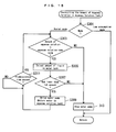
- the system checks on whether or not the electric energy stored in the secondary battery 108 is smaller than the low-consumption energy (the first threshold value) (Step S9). If the electric energy stored in the secondary battery 108 is smaller than the low-consumption energy, the system determines that the start-up is impossible, stops starting the fuel cell system 10, and disables the vehicle (Step S11).
- Step S9 finds that the electric energy stored in the secondary battery 108 is not smaller than the low-consumption energy
- the system determines that the start-up is possible, and calculates normal-consumption energy which is used as a second threshold value (Step S13).
- the system checks on whether or not the electric energy stored in the secondary battery 108 is smaller than the normal-consumption energy (the second threshold value) (Step S15). If the electric energy stored in the secondary battery 108 is smaller than the normal-consumption energy, the system determines that it is impossible to start in the normal mode, and thus the system starts the fuel cell system 10 in the low consumption mode; however, driving of the vehicle is disabled (Step S17). As described, the fuel cell system 10 can be started even if the electric energy stored in the secondary battery 108 is not very large.
- Step S15 finds that the electric energy stored in the secondary battery 108 is not smaller than the normal-consumption energy, the system determines that a start-up in the normal mode is possible, and the process goes to Step S19.
- the load energy demand and the normal-consumption energy are added to each other, to be used as a third threshold value (Step S21).
- the system checks on whether or not the electric energy stored in the secondary battery 108 is smaller than the sum of the load energy demand and the normal-consumption energy (the third threshold value) (Step S23). If the electric energy stored in the secondary battery 108 is smaller, restriction will be placed on vehicle driving, and the system sets the amount of the restriction (Step S25). In the present embodiment, the restriction is placed on driving of the vehicle rear wheel. The restriction may be made in steps for example, with the amounts of restriction predetermined, and the setting being made to an amount appropriate to the electric energy stored in the secondary battery 108. Then, the fuel cell system 10 is started in the normal mode, and the vehicle is enabled for driving under a restrictive condition (Step S27).
- Step S23 finds that the electric energy stored in the secondary battery 108 is not smaller than the sum of the load energy demand and the normal-consumption energy, the fuel cell system 10 is started in the normal mode, and the vehicle is enabled for normal driving, so that the vehicle can be driven normally (Step S29).
- the start-up mode of the fuel cell system 10 and vehicle driving status may be displayed in the display unit 106.
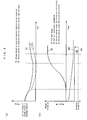
- Figs. 8 (a) and (b) describe a case where the fuel cell system 10 is started in the low consumption mode but the vehicle is disabled. If the electric energy stored in the secondary battery 108 has an initial value as shown in Fig. 8 (a), starting the fuel cell system 10 in the normal mode will result in a time course as indicated by in Broken Line A1; specifically, the electric energy stored in the secondary battery 108 will be zero during the start-up, becoming unable to continue the start-up process of fuel cell system 10 even if the vehicle is not driven. In this case therefore, the fuel cell system 10 is started not in the normal mode but in the low consumption mode where power generation is started with special limitations placed on the power consumed by the system components. Then, the electric energy stored in the secondary battery 108 will be as shown in Solid Line B1. It should be noted here that the limitations on the power consumed by the system components will be implemented by reducing the necessary time to attain the target temperature and limiting operation of the system components for example.
- FIG. 8 (b) shows the output of the fuel cell 12 when the system is started in normal mode
- Solid Line B2 shows the output of the fuel cell 12 when the system is started in low consumption mode
- Broken Line A3 shows the power consumption by the fuel cell system 10 when the system is started in normal mode
- Solid Line B3 shows the power consumption by the fuel cell system 10 when the system is started in the low consumption mode
- Solid Line B4 shows vehicle's average output when it is not driven.
- the low consumption mode will require a long time before the output of the fuel cell 12 reaches the normal level. Also, with reference to Broken Line A3 and Solid Line B3, the start-up in normal mode will require a power consumption of approximately 150W by the system components whereas the start-up in low consumption mode will decrease the power consumption by the system components to approximately 100W, making it possible to reduce energy consumption.
- Figs. 9 (a) and (b) describe a case where the fuel cell system 10 is started in the normal mode and the vehicle is enabled for restrictive driving. If the electric energy stored in the secondary battery 108 has an initial value as shown in Fig. 9(a), starting the fuel cell system 10 in the normal mode will result in a time course as indicated by Broken Line C1; specifically, since the electric energy stored in the secondary battery 108 is small, the electric energy stored in the secondary battery 108 will be zero during the start-up, and it will become unable to continue the start-up process of fuel cell system 10. In this case therefore, the fuel cell system 10 is started in the normal mode but vehicle driving is restricted. Then, the electric energy stored in the secondary battery 108 will be as shown in Solid Line D1.
- Solid Line D2 shows the output of the fuel cell 12 when the system is started in normal mode
- Solid Line D3 shows the power consumption by the fuel cell system 10 when the system is started in normal mode
- Solid Line D4 shows a vehicle's average output when the vehicle is driven under a restricted condition
- Broken Line C4 shows the vehicle's average output when it is driven normally.
- the vehicle's average output is restricted from a state indicated by Broken Line C4 to a state indicated by Solid Line D4.
- Figs. 10 (a) and (b) describe a case where the fuel cell system 10 is started in normal mode and the vehicle is enabled for normal driving. If the electric energy stored in the secondary battery 108 has an initial value as shown in Fig. 10 (a), the fuel cell system 10 is started in normal mode and the vehicle is enabled for normal driving. Then, as shown in Solid Line E1, the electric energy stored in the secondary battery 108 will decrease due to energy consumption by the system components of fuel cell system 10 and by the vehicle until a certain time point t is reached.
- the output from the fuel cell 12 stabilizes at a level not lower than the amount of energy consumed by the system components and the vehicle, where there is no longer energy deficit from the secondary battery 108, thus the system components and the vehicle are driven by the output from the fuel cell 12, and the secondary battery 108 starts to be charged.
- the secondary battery 12 has a surplus in its stored electric energy, and it is possible to start the system in the normal mode and to drive the vehicle normally.
- Solid Line E2 shows the output of the fuel cell 12 when the system is started in normal mode
- Solid Line E3 shows the power consumption by the fuel cell system 10 when the system is started in normal mode
- Solid Line E4 shows a vehicle's average output when the vehicle is driven normally.
- Fig. 8(b), Fig. 9(b) and Fig. 10(b) show vehicle's average outputs.
- Fig. 11 shows an example where a restriction is placed on the vehicle's output.
- Fig. 11(a) shows an example, where the vehicle's output is restricted by limiting a maximum current of the motor 116. From Fig. 11(a), it is clear that limiting a maximum current of the motor 116 reduces drive power of the rear wheel, making it possible to reduce energy consumption.
- Fig. 11(b) shows an example where the vehicle's output is restricted by limiting a maximum output of the motor 116. It is clear that limiting a maximum output of the motor 116 reduces drive power of the rear wheel as indicated by hatching in Fig. 11(b), making it possible to reduce energy consumption.
- the amount of electric energy which must be stored in the secondary battery 12 depends upon the temperature at the time of starting the fuel cell 12. Specifically, if the temperature at the time of start-up is 20°C, stored electric energy F1 is necessary. At 30°C, stored electric energy F2 is necessary, and at 40°C, stored electric energy F3 is necessary. In essence, the amount of stored electric energy required in the secondary battery 108 is smaller if the temperature at the time of start-up is higher. It should be noted here that the amounts of stored electric energy F1 through F3 each represent stored electric energy which is necessary for starting the fuel cell system 10 in the normal mode, with the vehicle enabled for normal driving.
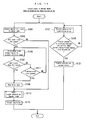
- Step S17 description will be made for a subroutine in Step S17, Fig. 7, i.e. an operation in the case where the fuel cell system 10 is started in low consumption mode but the vehicle is disabled.
- the fuel cell system 10 is started in the low consumption mode, power generation is started (Step S51), and the process then moves to normal operation (Step S53).
- Step S55 the vehicle, i.e. the load, is disabled at first (Step S55). Specifically, no voltage is applied to the motor 116, thus the motor 116 is not drivable, and this state is maintained until Step S57 finds that the electric energy stored in the secondary battery 108 is not lower than the normal-consumption energy (the second threshold value). In other words, only a charging operation of the secondary battery 108 is performed until the secondary battery 108 has been charged to a certain extent. Once the electric energy stored in the secondary battery 108 is not lower than the normal-consumption energy, the vehicle is enabled for driving under a restricted condition (for example, with a limit on a maximum current of the motor 116) (Step S59).
- a restricted condition for example, with a limit on a maximum current of the motor 116
- Step S61 finds that a new calculation of the electric energy stored in the secondary battery 108 is not lower than the sum (the third threshold value) of the normal-consumption energy and the load energy demand.
- the restriction is removed, and the vehicle is enabled for normal driving (Step S63).
- the load is switched to normal driving. With this arrangement, it is possible to drive the load in a mode appropriate to the electric energy stored in the secondary battery 108.
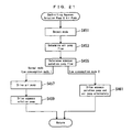
- Step S101 the level sensor 54 detects the amount of liquid (amount of water) in the water tank 44 (Step S101). If the amount of liquid detected in Step S101 is not smaller than a first predetermined amount (250 cc for example) which is a value set in advance (Step S103: YES), the water pump 60 is driven by the power from the secondary battery 108, to return water from the water tank 54 through the water returning pipe 58, to the aqueous solution tank 18 (Step S105). Thereafter, when the amount of liquid detected by the level sensor 54 is not greater than a second predetermined amount (220 cc for example) which is a value set in advance (Step S107: YES), the water pump 60 is stopped (Step S109).
- a second predetermined amount 220 cc for example
- Step S107: NO even if the amount of liquid detected by the level sensor 54 is greater than the second predetermined amount in Step S107 (Step S107: NO), the process goes to Step S109 after a lapse of a predetermined amount of time (Step S111: YES).
- Step S111: YES the water pump 60 is stopped after a lapse of a predetermined amount of time, eliminating a problem that the second predetermined amount is never detected and power generation is never started due to a malfunction in the level sensor 54 for example.
- the operation in Step S105 is continued until the predetermined amount of time has lapsed (Step S111: NO).
- Step S109 system components such as the fuel pump 20, the aqueous solution pump 26, the air pump 34, the heat-exchanger cooling fan 32, the gas-liquid separator cooling fan 48 and the water pump 60 are driven, and power generation in the normal mode is started (Step S113). If Step S103 finds that the amount of liquid in the water tank 44 is smaller than the first predetermined amount (Step S103: NO), the process goes to Step S113. As described, normal operation is allowed (Step S115) after power generation in the normal mode is started.
- the vehicle i.e. the load
- the vehicle is enabled for restrictive driving (for example, with a limit on a maximum current of the motor 116) at first (Step S117).
- This condition for driving the vehicle is maintained until Step S119 finds that a new calculation of the electric energy stored in the secondary battery 108 gives a value not lower than the sum (the third threshold value) of the normal-consumption energy and the load energy demand.
- the vehicle is enabled for normal driving (Step S121).
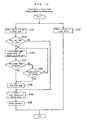
- Step S151 the level sensor 54 detects the amount of liquid (amount of water) in the water tank 44 (Step S151). If the amount of liquid detected in Step S151 is not smaller than the first predetermined amount (250 cc for example) which is a value set in advance (Step S153: YES), the water pump 60 is driven by the power from the secondary battery 108, to return water from the water tank 54 through the water returning pipe 58 into the aqueous solution tank 18 (Step S155). Thereafter, when the amount of liquid detected by the level sensor 54 is not greater than the second predetermined amount (220 cc for example) which is a value set in advance (Step S157: YES), the water pump 60 is stopped (Step S159).
- Step S157 NO
- the process goes to Step S159 after a lapse of a predetermined amount of time (a minute for example) (Step S161: YES).
- a predetermined amount of time a minute for example
- Step S161: YES a predetermined amount of time
- the water pump 60 is stopped after a lapse of a predetermined amount of time, eliminating a problem that the second predetermined amount is never detected and power generation is never started due to a malfunction in the level sensor 54 for example.
- the operation in Step S155 is continued until the predetermined amount of time has lapsed (Step S161: NO).
- Step S159 system components such as the fuel pump 20, the aqueous solution pump 26, the air pump 34, the heat-exchanger cooling fan 32, the gas-liquid separator cooling fan 48 and the water pump 60 are driven, and power generation in the normal mode is started (Step S163). If Step S153 finds that the amount of liquid in the water tank 44 is smaller than the first predetermined amount (Step S153: NO), the process goes to Step S163. As described, normal operation is allowed (Step S165) after power generation in the normal mode is started.
- Step S167 no limitation is set to the output of the vehicle, i.e. the load, and normal driving is allowed from the first place (Step S167).
- Step S201 the system is brought to a state of no load. Specifically, the voltage adjustment circuit 88 opens the electric circuit 90 to drive the fuel cell 12 with no load, and the connection between the fuel cell 12 and the secondary battery 108 is cut off. Under this state, tapping of electric current from the fuel cell 12 is stopped. Then, an alarm level is determined (Step S202).
- Step S203 the amount of aqueous solution in the aqueous solution tank 18 is controlled (Step S203), the concentration of aqueous methanol solution S is controlled (Step S205), and the amount of aqueous solution in the aqueous solution tank 18 is decreased (Step S207). Further, the aqueous solution pump 26 and the air pump 34 are controlled (Step S209), and the output voltage of the fuel cell 12 is controlled (Step S211).
- Steps S201 through S211 in Fig. 16 will be described in more specifically:
- a lower value is set for the predetermined voltage than when starting the system in normal mode, whereby the connection between the fuel cell 12 and the secondary battery 108 is not cut off (the connection is maintained) and charging to the secondary battery 108 is continued in the low consumption mode, even in cases where the output voltage of the fuel cell 12 reaches a value at which the connection between the fuel cell 12 and the secondary battery 108 would be cut off in the normal mode.
- This makes it possible to reduce discharge from the secondary battery 108, i.e. to cut down on a decrease in the stored electric energy.
- Step S301 the mode is checked.
- the system checks on whether or not the amount of aqueous solution detected in the aqueous solution tank 18 by the level sensor 22 is smaller than a predetermined amount of the aqueous solution tank (the amount of aqueous solution in the aqueous solution tank 18 during power generation, which may be one liter for example) (Step S303).
- the level sensor 54 detects the amount of liquid (amount of water) in the water tank 44 (Step S305), and the system checks on whether or not the detected amount of liquid is not smaller than a first predetermined amount (250 cc for example) (Step S307). If the detected amount of liquid is not smaller than the first predetermined amount, the water pump 60 is driven and water is returned to the aqueous solution tank 18 (Step S309) . This operation is continued until Step S311 finds that a predetermined amount of time has passed, and the process goes back to Step S303 if the predetermined amount of time has passed.
- a first predetermined amount 250 cc for example
- Step S303 finds that the amount of aqueous solution in the aqueous solution tank 18 is not smaller than the predetermined amount, or Step S307 finds that the amount of liquid is smaller than the first predetermined amount, the water pump 60 is stopped (Step S313).
- the concentration of the aqueous methanol solution S is set to be higher than the concentration for the normal operation.
- Step S351 mode detection is made to see if the current mode is normal mode or low consumption mode (Step S351). Then, the concentration sensor 64 detects the concentration of aqueous methanol solution S (Step S353), and the system checks on whether or not the detected concentration of aqueous methanol solution S is lower than a predetermined concentration for the detected mode (Step S355).
- the predetermined concentration is assigned to each mode, and the concentration value is different between the normal mode and the low consumption mode. Although the predetermined concentration in the normal mode varies depending upon the temperature of the fuel cell 12, an ambient temperature, etc., the value is higher than the concentration for the normal operation.
- the value is even higher than the setting for the normal mode by approximately 2 wt% through 5 wt%.
- the predetermined concentration is set to 6% for normal mode and 8% for low consumption mode.
- Step S355 finds that the concentration of aqueous methanol solution S is lower than the predetermined concentration
- the fuel pump 20 is driven (Step S357) .
- the operation is continued until Step S359 finds that a predetermined amount of time has passed.
- Step S355 finds that the concentration of aqueous methanol solution S is not lower than the predetermined concentration
- the fuel pump 20 is stopped (Step S361).
- Step S401 the mode is checked.
- the water pump 60 is driven to move aqueous methanol solution S from the aqueous solution tank 18 to the water tank 44, whereby the amount of aqueous methanol solution S in the aqueous solution tank 18 is decreased (Step S403).
- the water pump 60 is not driven in low consumption mode, i.e. the control process of decreasing the amount of aqueous methanol solution S in the aqueous solution tank 18 is not performed.
- Step S451 mode detection is made to see if the current mode is normal mode or low consumption mode. Then, the system determines an amount of air flow to be supplied by the air pump 34 for the detected mode (Step S453). For example, in a normal mode, the amount of air flow to be supplied by the air pump 34 is set to three times the theoretical demand, and two times the theoretical demand in a low consumption mode 1. It should be noted here that the amount of air flow to be supplied by the air pump 34 in the low consumption mode 1 is preferably not smaller than 20% and smaller than 100% of the value for the normal mode.
- the system determines an amount of flow of aqueous methanol solution S to be supplied by the aqueous solution pump 26, for the detected mode (Step S455).
- the amount of flow of aqueous solution to be supplied by the aqueous solution pump 26 is set to the same amount as in normal power generation, whereas the flow is set to a minimum required in the low consumption mode 1.
- the air pump 34 is driven, and the amount of air flow determined for the particular mode is supplied to the cathode 12c of the fuel cell 12 (Step S457).
- the aqueous solution pump 26 is driven, and the amount of flow of aqueous methanol solution S determined for the mode is supplied to the anode 12b of the fuel cell 12 (Step S459).
- Step S461 the aqueous solution pump 26 and the air pump 34 are driven alternately with each other. This prevents excessive voltage drop caused by driving both of the pumps simultaneously.
- power consumption by the air pump 34 can be decreased when starting in the low consumption mode 1 by starting power generation with a lower output of the air pump 34 than in the normal mode.
- the amount of flow is decreased in the supply of air and aqueous methanol solution S, and the air pump 34 and the aqueous solution pump 26 are driven alternately and not simultaneously. This makes it possible to reduce power consumption by the air pump 34 and the aqueous solution pump 26, and therefore to cut down on a decrease in the electric energy stored in the secondary battery 108.
- Step S501 mode detection is made to see if the current mode is normal mode or low consumption mode.
- the system checks on whether or not the output voltage of the fuel cell 12 is not lower than the voltage of the secondary battery 108 (Step S503), and the process waits until the output voltage of the fuel cell 12 is not lower than the voltage of the secondary battery 108.
- the output voltage of the fuel cell 12 is set to V1 which is a value for the low consumption mode (Step S505).
- the system checks on whether or not the temperature of the fuel cell 12 has reached a predetermined temperature (Step 5507), and the process waits until the temperature of the fuel cell 12 has reached the predetermined temperature.
- the process goes to Step S505, and the output voltage of the fuel cell 12 is set to V1 which is the value for the normal consumption mode.
- the output voltage of the fuel cell 12 is set by the voltage adjustment circuit 88.
- a temperature T of the fuel cell 12 is checked (Step S509), and the output voltage of the fuel cell 12 is set, based on the mode and the temperature T. If the temperature T is not higher than T1, the process waits until a predetermined amount of time has passed (Step 5511). When the predetermined amount of time has passed, the system checks on whether or not the output voltage of the fuel cell 12 is smaller than a predetermined voltage (Step S513). In terms of single-cell voltage, the system checks, for example, if the single-cell voltage is lower than 0.25V for the normal mode, or if the single-cell voltage is lower than 0.2V for the low consumption mode.
- Step S201 the process goes back to Step S201 in Fig. 16, where the system is set to no load, and tapping of the electric current from the fuel cell 12 is stopped.
- the output voltage of the fuel cell 12 is not lower than the predetermined voltage, tapping of electric current from the fuel cell 12 is continued, and the process goes back to Step S509.
- Step S509 finds that the temperature T is higher than T1 and not higher than T2, the output voltage of the fuel cell 12 is set to V2 (Step S515), and the process goes to Step S511.
- the output voltage of the fuel cell 12 is set to V3 (Step S517), and the system checks on whether or not the temperature T of the fuel cell 12 has reached the target temperature (normal operation temperature) (Step S519). If the temperature T has not yet reached the target temperature, the process goes to Step S511, whereas if the target is reached, the process returns and brings the fuel cell system 10 to normal operation.
- the single-cell voltages corresponding to the voltages V1, V2 and V3 are 0.50V, 0.40V and 0.35V for normal mode respectively, while being 0.40V, 0.35V and 0.25V for low consumption mode respectively. Lowering the output voltage of the fuel cell 12 makes it possible to increase the charge current to the secondary battery 108.
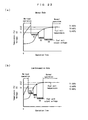
- Fig. 23 (a) shows the temperature of the fuel cell 12 and the output voltage of the fuel cell 12 in the normal mode.
- Fig. 23 (b) shows the temperature of the fuel cell 12 and the output voltage of the fuel cell 12 in the low consumption mode.
- output voltage setting values V1, V2 and V3 from the fuel cell 12 are lower than those when starting the system in normal mode at the same fuel cell temperature. This makes it possible to increase the output current from the fuel cell 12 in low consumption mode over the output current in normal mode, and thereby to charge the secondary battery 108 quickly. Temperature rise in the fuel cell 12 is quicker, too, and it is possible to switch to normal operation at an earlier time.
- a start-up mode of the fuel cell system 10 is determined on the basis of electric energy stored in the secondary battery 108 and a threshold value obtained from calculation, and the fuel cell system 10 is operated in accordance with the determined start-up mode. This makes it possible to select an optimum start-up mode suitable for the electric energy (amount of charge) stored in the secondary battery 108, eliminating a trouble when starting the fuel cell system 10.
- the amount of charge in the secondary battery 108 is converted into an amount of stored electric energy, and this stored electric energy is compared to the first threshold value which is the low-consumption energy itself i.e. the amount of energy necessary for starting the fuel cell system 10 in low consumption mode. If the electric energy stored in the secondary battery 108 is not smaller than the first threshold value, the fuel cell system 10 is started. On the other hand, if the electric energy stored in the secondary battery 108 is smaller than the first threshold value, the system determines that the fuel cell system 10 cannot be started even in the low consumption mode, and stops starting the fuel cell system 10. This makes it possible to avoid unnecessary energy consumption.
- the first threshold value is the low-consumption energy itself i.e. the amount of energy necessary for starting the fuel cell system 10 in low consumption mode.
- the fuel cell system 10 is started in normal mode.
- the electric energy stored in the secondary battery 108 is not smaller than the second threshold value which is the normal-consumption energy itself, i.e. the amount of energy which is necessary to start the fuel cell system 10 in normal mode.
- the fuel cell system 10 is started in low consumption mode. Following the process described above, it is possible to start the fuel cell system 10 in a mode appropriate for the electric energy stored in the secondary battery 108.
- the vehicle is enabled for normal driving.
- the vehicle is enabled for driving in a mode other than the normal driving. As described, the vehicle is made drivable within a range allowable by the electric energy stored in the secondary battery 108.
- the fuel cell system 10 described above is suitably used in vehicles which require that the capacity of the secondary battery 108 be small.
- the thresholds are provided by values of energy, and the threshold values are compared to the electric energy stored in the secondary battery 108; however, the present invention is not limited to this.
- the thresholds may be provided by the amount of charge, so that those threshold values are compared to the amount of charge in the secondary battery 108. In this case, energy is converted to the amount of charge so that it can be used as a threshold value.
- the thresholds may be provided by the voltage, so that those threshold values are compared to the voltage values of the secondary battery 108; or the thresholds may be provided by the current, so that those threshold values are compared to the values of current flowing in the secondary battery 108.
- threshold values for determining the start-up mode is obtained by calculation; however, this may be replaced by the following arrangement.
- three threshold values A, B and C are predetermined for the amount of charge in the secondary battery 108, to define four categories. In this case, after the main switch is turned ON, the amount of charge in the secondary battery 108 is detected, the category in which the amount of charge falls is found, and a process assigned to this particular category is performed.
- the fuel cell system 10 is not started, or the vehicle is not enabled, either. If the amount of charge is greater than the threshold value A and not greater than the threshold value B, the fuel cell system 10 is started in low consumption mode but the vehicle is not enabled. If the amount of charge is greater than the threshold value B and not greater than the threshold value C, the fuel cell system 10 is started in normal mode and the vehicle is enabled for restrictive driving. If the amount of charge is greater than the threshold value C, the fuel cell system 10 is started in the normal mode and the vehicle is enabled for normal driving.
- the start-up mode can be set easily.
- operation speed of the CPU 72 may be lowered in low consumption mode to reduce power consumption.
- three operation modes may be defined by using a threshold value D which represents a normal amount of energy necessary for making a normal start of the fuel cell system 10, and a threshold value E which represents a sum of the normal amount of energy necessary for starting of the fuel cell system 10 in normal mode and the load energy demand necessary for making normal driving of the load (D ⁇ E).
- a threshold value D which represents a normal amount of energy necessary for making a normal start of the fuel cell system 10
- a threshold value E which represents a sum of the normal amount of energy necessary for starting of the fuel cell system 10 in normal mode and the load energy demand necessary for making normal driving of the load
- the fuel cell system 10 is started in normal mode and the vehicle is enabled for normal driving.
- the threshold values D, E may be obtained by calculation based on the temperature of fuel cell 12 or may be predetermined.
- start-up mode of the fuel cell system 10 may be determined on the basis of data concerning electric energy stored in the secondary battery 108, without using threshold values.
- the present invention is used suitably in direct methanol fuel cell systems in which it takes time for raising a temperature of aqueous fuel solution, i.e. until a sufficient output is obtained from the fuel cell.
- methanol is used as fuel and aqueous methanol solution is used as fuel aqueous solution; however the present invention is not limited by this, and the fuel may be provided by other alcoholic fuels such as ethanol, and the aqueous fuel solution may be provided by aqueous solutions of the alcohol, such as aqueous ethanol solution.
- the load may be provided by any transportation equipment other than motorbikes, such as automotive vehicles including four-wheeled automobiles, marine vessels and aircraft.
- the present invention is applicable also to fuel cell systems mounted with a reformer, and fuel cell systems where hydrogen is supplied to the fuel cell. Further, the present invention is applicable to small, stationary-type fuel cell systems.
Abstract
Description
- The present invention relates to fuel cell systems and driving methods therefor, and more specifically, to a fuel cell system including a secondary battery which is electrically connected with a fuel cell, and a method of starting the system.
- Fuel cells take time until they attain a temperature appropriate for power generation, after being started at an ambient temperature. While the temperature is low, the fuel cells' power generation output is low. When starting, therefore, fuel cell systems obtain energy from other power supplying means than the fuel cell in order to drive their system components, etc. Fuel cell systems cannot start themselves without an energy supplier other than the fuel cell. Further, even if a fuel cell system has an energy supplier such as a secondary battery, a problem will be encountered during a start-up of the fuel cell system if there is not sufficient supply of energy from the secondary battery until the fuel cell has attained a temperature appropriate for sufficient power generation.
- A fuel cell system which includes a secondary battery is disclosed in
Patent Document 1 for example.
Patent Document 1 discloses a technique for supplying a load with electric power from a secondary battery when the system is started, during which warming-up state of the fuel cell is monitored. When it is determined that the fuel cell is warmed up to a sufficient level, the fuel cell is connected with the load so that the fuel cell supplies electric power to the load.
Patent Document 1:JP-A 9-231991 - However, the fuel cell system according to
Patent Document 1 does not monitor the amount of energy stored in the secondary battery, and therefore can fail to start the fuel cell system if sufficient power is not stored in the secondary battery. - Therefore, a primary object of the present invention is to provide a fuel cell system and a starting method therefor, capable of setting a start mode appropriate to the energy stored in the secondary battery so as to prevent a trouble when the system is started.
- According to an aspect of the present invention, there is provided a fuel cell system connected with a load. The fuel cell system includes: a fuel cell; a secondary battery electrically connected with the fuel cell; means for obtaining data concerning electric energy stored in the secondary battery; and first determination means for determining one from a plurality of start-up modes differing from each other in energy consumption, for the fuel cell system based on the obtained data concerning electric energy stored in the secondary battery.
- According to another aspect of the present invention, there is provided a method of starting a fuel cell system connected with a load. The system includes a fuel cell and a secondary battery electrically connected with the fuel cell. The method includes a sequence of: obtaining data concerning electric energy stored in the secondary battery; determining one from a plurality of start-up modes differing from each other in energy consumption, for the fuel cell system based on the obtained data concerning electric energy stored in the secondary battery; and operating the fuel cell system in accordance with the determined mode.
- According to the present invention, a start-up mode of a fuel cell system is determined based on data concerning electric energy stored in the secondary battery, and the fuel cell system is operated in accordance with the determined start-up mode. This makes it possible to select a start-up mode which is appropriate to the electric energy stored in the secondary battery, and eliminate a trouble in starting the fuel cell system.
- Preferably, the start-up mode of the fuel cell system is determined based on the data concerning electric energy stored in the secondary battery and at least one threshold value for determining the start-up mode of the fuel cell system. In this case, it is possible to select an optimum start-up mode for the fuel cell system.
- Further preferably, the threshold value includes a first threshold value representing the energy necessary for starting the fuel cell system. Whether or not to start the fuel cell system is determined, based on the data concerning electric energy stored in the secondary battery and the first threshold value. For example, in a case where the data concerning stored electric energy refers to the stored electric energy itself, and the first threshold value represents the very energy necessary for starting the fuel cell system, the fuel cell system is started if the electric energy stored in the secondary battery is not smaller than the first threshold value. On the other hand, if the electric energy stored in the secondary battery is smaller than the first threshold value, starting of the fuel cell system is stopped, based on a judgment that it is impossible to start the fuel cell system. This makes it possible to avoid unnecessary consumption of energy.
- Further, preferably, the threshold value includes a second threshold value representing normal-consumption energy necessary for starting the fuel cell system in a normal mode. With this arrangement, whether to start the fuel cell system in the normal mode or in a low consumption mode is determined, based on the data concerning electric energy stored in the secondary battery and the second threshold value. For example, in a case where the data concerning stored electric energy refers to the very electric energy stored in the secondary battery, and the second threshold value represents the normal-consumption energy itself which is necessary for starting the fuel cell system in the normal mode, the fuel cell system is started in the normal mode if the electric energy stored in the secondary battery is not smaller than the second threshold value. On the other hand, if the electric energy stored in the secondary battery is smaller than the second threshold value, the fuel cell system is started in the low consumption mode. In this way, the fuel cell system is started in a mode which is appropriate to the electric energy stored in the secondary battery.
- Preferably, a third threshold value which represents a sum of the normal-consumption energy necessary for starting the fuel cell system in the normal mode and a load energy demand necessary for driving the load normally is further used. With this arrangement, whether or not to drive the load normally is determined, based on the data concerning electric energy stored in the secondary battery and the third threshold value. The load is driven normally or in a mode other than normal driving in accordance with a result of the determination. For example, in a case where the data concerning the stored electric energy refers to the stored electric energy itself, and the third threshold value represents the very sum of the normal-consumption energy and the load energy demand, the load is enabled for normal driving if the electric energy stored in the secondary battery is not lower than the third threshold value. On the other hand, if the electric energy stored in the secondary battery is smaller than the third threshold value, the load is enabled for a mode other than normal driving; or more specifically, the load is enabled for a mode where energy consumable by the load is limited, and the load can be driven under a restrictive condition. As described, the load is enabled for driving within a range allowable by the electric energy stored in the secondary battery.
- Further preferably, when the fuel cell system is started in the low consumption mode, a predetermined voltage for determining on whether or not the fuel cell is disconnected from the secondary battery is set to a lower value than when started in the normal mode. The determination on whether or not the fuel cell is disconnected from the secondary battery is based on the fuel cell' s output voltage and the predetermined voltage. When starting the system in the low consumption mode, the predetermined voltage is set to a lower value than when started in the normal mode, whereby the connection between the fuel cell and the secondary battery is not cut off (the connection is maintained) and charging to the seconding battery is continued in the low consumption mode, even in a case where the output voltage of the fuel cell has reached a value (which is smaller than the predetermined voltage of the normal mode) at which the connection between the fuel cell and the secondary battery would be cut off in the normal mode. This makes it possible to reduce discharge from the secondary battery, i.e. to cut down on a decrease in the stored electric energy. This arrangement provides a particular advantage when the fuel cell system is started in an environment where the fuel cell's temperature is low and therefore the fuel cell's output voltage is likely to be low.
- Further, preferably, the invention makes use of an aqueous solution tank which stores aqueous fuel solution to be supplied to the fuel cell, an amount of aqueous solution in the aqueous solution tank is not controlled when the fuel cell system is started in the low consumption mode. In this case, there is no need for driving a pump for example, which makes it possible to reduce power consumption.
- Preferably, when the fuel cell system is started in the low consumption mode, the fuel cell is supplied with aqueous fuel solution which has a higher concentration than a concentration used when the system is started in the normal mode, to start power generation. In this case, the fuel cell's temperature rises quickly, making possible to shorten the necessary time to attain the target temperature, although efficiency is decreased because of increased crossover.
- Further preferably, no control is performed for decreasing the amount of aqueous solution in the aqueous solution tank when the fuel cell system is started in the low consumption mode. In this case, there is no need to drive a pump for example, which makes it possible to reduce power consumption.
- Further, preferably, the invention makes use of an air pump which supplies the fuel cell with air containing oxygen. When the fuel cell system is started in the low consumption mode, the air pump is operated at a lower output than when started in a normal mode, to start power generation. In this case, it is possible to reduce power consumption by the air pump.
- Preferably, the invention makes use of an air pump which supplies the fuel cell with air containing oxygen, and an aqueous solution pump which supplies the fuel cell with aqueous fuel solution. When the fuel cell system is started in the low consumption mode, flow of air and aqueous fuel solution is reduced, and the air pump and the aqueous solution pump are driven alternately with each other. As described, by not driving the air pump and the aqueous solution pump simultaneously, it becomes possible to reduce power consumption by the air pump and the aqueous solution pump, and cut down on a decrease in the electric energy stored in the secondary battery.
- Further preferably, when starting the fuel cell system in the low consumption mode, the fuel cell system is connected with the load when the fuel cell' s output voltage is not lower than a voltage in the secondary battery. In this case, if the fuel cell' s output voltage becomes not lower than the voltage of the secondary battery, it is possible to terminate no-load operation of the fuel cell even if the fuel cell has not yet attained a predetermined temperature (a temperature serving as a threshold to terminate no-load operation in the normal mode). This makes it possible to shorten the time for the no-load operation and the time to attain the target temperature.
- Further, preferably, when the fuel cell system is started in the low consumption mode, the fuel cell is operated at a lower output voltage than when started in a normal mode at the same temperature of the fuel cell. This makes it possible to increase an output current from the fuel cell and to charge the secondary battery quickly.
- Preferably, while the load is driven in a mode other than normal driving, the load is switched to normal driving when electric energy stored in the secondary battery is not lower than energy represented by the third threshold value. This arrangement makes it possible to drive the load in a mode appropriate to the amount of charge in the secondary battery.
- In fuel cell systems where the fuel cell is supplied with aqueous fuel solution for power generation, it takes time until the temperature of aqueous fuel solution rises, i.e. sufficient output is obtained from the fuel cell, since the aqueous fuel solution itself has a large thermal capacity. Therefore, the present invention can be used suitably in those fuel cell systems where the fuel cell is supplied with aqueous fuel solution for power generation.
- Also, the present invention can be used suitably in transportation equipment which requires that, if the fuel cell system is to be mounted, the capacity of the secondary battery be small. Specifically, the present invention can be used suitably in cases where at least one of the loads is a motor of the transportation equipment.
- It should be noted here that the meaning of the term "data concerning stored electric energy" is not limited to the stored electric energy itself, but may mean a value which has a one-to-one relationship with the stored electric energy (e.g. a value convertible to and from the amount of stored electric energy) such as the amount of electric charge, voltage, current, etc.
- The term "energy necessary for starting the fuel cell system" means energy necessary for a fuel cell system to start and attain a temperature (target temperature) at which the fuel cell can sufficiently perform power generation.
- Meaning of the term "threshold value corresponding to the energy" is not limited to energy itself, but may mean a value which has a one-to-one relationship with the energy (e.g. a value convertible to and from the energy) such as the amount of electric charge, voltage, current, etc.
- The term "normal mode" is a mode of operating a fuel cell system, where no restriction is placed on operations of system components, etc. when the fuel cell system is started.
- The term "low consumption mode" is a mode of operating a fuel cell system, where restrictions are placed on operations of system components, etc. when the fuel cell system is started. Energy consumption is smaller than in the normal mode.
- The term "load energy demand" is energy necessary for driving the load normally until a fuel cell attains a temperature (target temperature) at which the fuel cell can sufficiently perform power generation.
- "Normal drive (or to drive normally)" means driving without restriction.
- The above-described object, other objects, characteristics, aspects and advantages of the present invention will become clearer from the following detailed description of embodiments to be made with reference to the attached drawings.
-
- Fig. 1 is a schematic diagram showing a primary portion of a fuel cell system according to the present invention.
- Fig. 2 is a perspective view showing a state where the fuel cell system is mounted on a frame of a motorbike.
- Fig. 3 is a schematic diagram showing a primary portion of the fuel cell system.
- Fig. 4 is a block diagram showing an electric configuration of the fuel cell system.
- Fig. 5(a) is a graph showing time course changes of a fuel cell temperature after a fuel cell system is started; Fig. 5(b) is a graph showing a relationship between a temperature of a fuel cell when a fuel cell system is started and a necessary time to attain a target temperature.
- Fig. 6 is a circuit diagram showing a voltage control unit.
- Fig. 7 is a flowchart showing an example of main operation performed when the fuel cell system is started.
- Fig. 8 is a graph for describing a case where the fuel cell system is started in a low consumption mode but a vehicle is not enabled for driving.
- Fig. 9 is a graph for describing a case where the fuel cell system is started normally and the vehicle is enabled for restrictive driving.
- Fig. 10 is a graph for describing a case where the fuel cell system is started normally and the vehicle is enabled for normal driving.
- Fig. 11 includes graphs showing cases where a restriction is made on vehicle's output: Fig. 11(a) shows a case where maximum motor current is limited; Fig. 11(b) shows a case where maximum motor output is limited.
- Fig. 12 is a graph showing that stored electric energy necessary in a secondary battery varies depending upon the temperature at a time when the fuel cell system is started.
- Fig. 13 is a flowchart showing an operation in a case where the fuel cell system is started in a low consumption mode but the vehicle is not enabled for driving.
- Fig. 14 is a flowchart showing an operation in a case where the fuel cell system is started in a normal mode and the vehicle is enabled for restrictive driving.
- Fig. 15 is a flowchart showing an operation in a case where the fuel cell system is started in the normal mode and the vehicle is enabled for normal driving.
- Fig. 16 is a flowchart showing an operation performed at a time when power generation is started.
- Fig. 17 is a flowchart showing a process of determining an alarm level.
- Fig. 18 is a flowchart showing a process of controlling an amount of aqueous solution in an aqueous solution tank.
- Fig. 19 is a flowchart showing a process of controlling a concentration of aqueous methanol solution.
- Fig. 20 is a flowchart showing a process of decreasing the amount of aqueous solution in the aqueous solution tank.
- Fig. 21 is a flowchart showing a process of controlling an aqueous solution pump and an air pump.
- Fig. 22 is a flowchart showing a process of controlling an output voltage of a fuel cell.
- Fig. 23(a) is a graph showing a fuel cell's temperature and output voltage with respect to operating time in a normal mode; Fig. 23(b) is a graph showing the fuel cell's temperature and output voltage with respect to the operating time in a low consumption mode.
- Fig. 24 is a schematic diagram for describing another embodiment of the present invention.
-
- 10
- Fuel cell system
- 12
- Fuel cell
- 18
- Aqueous solution tank
- 20
- Fuel pump
- 26
- Aqueous solution pump
- 32
- Heat-exchanger cooling fan
- 34
- Air pump
- 44
- Water tank
- 48
- Gas-liquid separator cooling fan
- 60
- Water pump
- 64
- Concentration sensor
- 66
- Cell temperature sensor
- 70
- Control circuit
- 72
- CPU
- 76
- Volatile memory
- 78
- Non-volatile memory
- 84
- Voltage detection circuit
- 108
- Secondary battery
- 112
- Secondary-battery charge-amount detection unit
- 116
- Motor
- S
- Aqueous methanol solution
- Hereinafter, embodiments of the present invention will be described with reference to the drawings.
As shown in Fig. 1 through Fig. 4, afuel cell system 10 as an embodiment of the present invention is provided as a direct methanol fuel cell system. Since direct methanol fuel cell systems do not need a reformer, the systems are used suitably for equipment which requires portability, and equipment in which size reduction is desirable. Herein, description will be made for a case where thefuel cell system 10 is used in a motorbike taken as an example of transportation equipment. It should be noted here that the motorbike will be shown only as amotorbike frame 200 as in Fig. 2. In Fig. 2, the left side is the front side of the vehicle and the right side is the rear side thereof. Thefuel cell system 10 is disposed along themotorbike frame 200. Hereinafter, the motorbike may be referred to as a vehicle as necessary. - Referring mainly to Fig. 1, the
fuel cell system 10 includes afuel cell 12. Thefuel cell 12 is configured as a fuel cell stack constituted by a plurality of fuel cells connected (layered) in series. Each fuel cell includeselectrolyte 12a provided by a solid polymer film, as well as an anode (fuel electrode) 12b and a cathode (air electrode) 12c which sandwich theelectrolyte 12a. - Also, the
fuel cell system 10 includes afuel tank 14 which stores highly concentrated methanol fuel (aqueous methanol solution containing methanol at approximately 50 wt%) F. Thefuel tank 14 is connected with anaqueous solution tank 18 which stores aqueous methanol solution S, via a fuel supply pipe 16. The fuel supply pipe 16 is provided with afuel pump 20, and as thefuel pump 20 is driven, methanol fuel F in thefuel tank 14 is supplied to theaqueous solution tank 18. - The
fuel tank 14 is provided with alevel sensor 15 for detecting a height of liquid surface of the methanol fuel F in thefuel tank 14. Likewise, theaqueous solution tank 18 is provided with alevel sensor 22 for detecting a height of liquid surface of the aqueous methanol solution S in theaqueous solution tank 18. By detecting the height of liquid surfaces with thelevel sensors level sensor 54 to be described later. - The
aqueous solution tank 18 is connected with theanode 12b of thefuel cell 12 via anaqueous solution pipe 24. Theaqueous solution pipe 24 is provided with anaqueous solution pump 26, aradiator 28 which functions as a heat exchanger, and anaqueous solution filter 30, in this order from the upstream side. A coolingfan 32 is disposed near theradiator 28 in order to cool theradiator 28. Aqueous methanol solution S in theaqueous solution tank 18 is pumped toward theanode 12b by theaqueous solution pump 26, cooled by theradiator 28 as necessary, and further, purified by theaqueous solution filter 30 and then supplied to theanode 12b. - On the other hand, the
cathode 12c in thefuel cell 12 is connected with anair pump 34 via an air-side pipe 36. The air-side pipe 36 is provided with anair filter 38. Therefore, air from theair pump 34 which contains oxygen (oxidizer) is supplied to thecathode 12c after it is purified by theair filter 38. - Also, the
anode 12b and theaqueous solution tank 18 are connected with each other via apipe 40, through which theaqueous solution tank 18 receives unused aqueous methanol solution and produced carbon dioxide discharged from theanode 12b. - Further, the
cathode 12c is connected with awater tank 44 via apipe 42. Thepipe 42 is provided with aradiator 46 which functions as a gas-liquid separator, and near the radiator 46 a coolingfan 48 for cooling theradiator 46 is disposed. Thecathode 12c discharges an exhaust which contains moisture (water and water vapor). The exhaust is supplied to thewater tank 44 via thepipe 42. - Also, the
aqueous solution tank 18 and thewater tank 44 are connected with each other via a CO2 vent pipe 50. The CO2 vent pipe 50 is provided with amethanol trap 52 for separating aqueous methanol solution S. With this arrangement, carbon dioxide discharged from theaqueous solution tank 18 is supplied to thewater tank 44. - The
water tank 44 is provided with alevel sensor 54 for detecting a height of liquid in thewater tank 44. Also, anexhaust gas pipe 56 is attached to thewater tank 44. Through theexhaust gas pipe 56, carbon dioxide and exhaust from thecathode 12c are discharged. - The
water tank 44 is connected with theaqueous solution tank 18 via awater returning pipe 58. Thewater returning pipe 58 is provided with awater pump 60. Water in thewater tank 44 is returned to theaqueous solution tank 18 by driving thewater pump 60, as necessary, depending on the situation in theaqueous solution tank 18. - Also, along the
aqueous solution pipe 24, abypass pipe 62 is provided between theradiator 28 and theaqueous solution filter 30. - Referring also to Fig. 4, further, in the
fuel cell system 10, thebypass pipe 62 is provided with aconcentration sensor 64 for detecting the concentration of aqueous methanol solution S, and an aqueoussolution temperature sensor 65 for detecting the temperature of aqueous methanol solution S. Thefuel cell 12 is provided with acell temperature sensor 66 for detecting the temperature offuel cell 12, and anambient temperature sensor 68 for detecting the ambient temperature is provided near theair pump 34. It should be noted here that thecell temperature sensor 66 is disposed at a place in thefuel cell 12 where the highest temperature will be observed, e. g. near an outlet of the aqueous methanol solution S. - As shown in Fig. 4, the
fuel cell system 10 includes acontrol circuit 70. - The
control circuit 70 includes: aCPU 72 for performing necessary calculations and providing control over operations of thefuel cell system 10; aclock circuit 74 which provides theCPU 72 with clock signals; avolatile memory 76 provided by e.g. a DRAM for keeping elapsed time based on the clock signals provided to theCPU 72, flags, calculation data, etc; anon-volatile memory 78 provided by e.g. an EPROM or an SRAM for storing programs, data, etc, to control operations of thefuel cell system 10; areset IC 80 for preventing erroneous operation of thefuel cell system 10;interface circuits 82a through 82r for connection with external components; avoltage detection circuit 84 for detecting an output voltage of thefuel cell 12; acurrent detection circuit 86 for detecting an output electric current of thefuel cell 12; avoltage adjustment circuit 88 for adjusting the output voltage of thefuel cell 12; avoltage protection circuit 92 for protecting theelectric circuit 90 from over-voltage; adiode 94 placed in theelectric circuit 90 for protecting thefuel cell 12; apower source circuit 96 for providing theelectric circuit 90 with a voltage for a normal mode; and apower source circuit 98 for providing theelectric circuit 90 with a voltage for a low consumption mode. Thefuel cell system 10 is configured as a series type system which supplies a load with electric power via a secondary battery 108 (to be described later). - The
voltage detection circuit 84, thecurrent detection circuit 86, thevoltage adjustment circuit 88 and thediode 94 constitute avoltage control unit 100. - The
CPU 72 of thecontrol circuit 70 as described above is supplied with detection signals from theconcentration sensor 64, the aqueoussolution temperature sensor 65, thecell temperature sensor 66 and theambient temperature sensor 68, via theinterface circuits CPU 72 is supplied with detection signals from thelevel sensors interface circuits CPU 72 is supplied with detection signals from arollover switch 102 which detects rollover, via theinterface circuit 82n, as well as signals from aninput section 104 which is used for making various settings and information entry, via the interface circuit 82p. - Also, the
CPU 72 sends control signals to thefuel pump 20, theaqueous solution pump 26, theair pump 34, the heat-exchanger cooling fan 32, the gas-liquidseparator cooling fan 48 and thewater pump 60 via theinterface circuits CPU 72 controls these system components. Also, theCPU 72 sends control signals to adisplay unit 106 via theinterface circuit 82q, and controls thedisplay unit 106 which is a unit for displaying a variety of information and providing the rider of the motorbike with a variety of information. - Also, the
fuel cell 12 is connected with thesecondary battery 108 placed in abattery box 107. Thesecondary battery 108 complements the output from thefuel cell 12, is charged with electric energy from thefuel cell 12, and discharges the electric energy to supply power to a motor 116 (to be described later) and system components. Particularly, when starting power generation, system components are driven by electric energy from thesecondary battery 108, and as the amount of power generated by thefuel cell 12 increases, the electric energy is stored in thesecondary battery 108. Thesecondary battery 108 is provided by a nickel hydride battery, a lithium ion battery, a Ni-Cd battery, etc. Thesecondary battery 108 is connected with acontrol device 110. Thecontrol device 110 is constituted by a CPU, a memory, etc., and includes a secondary-battery charge-amount detection unit 112 which detects an amount of charge in thesecondary battery 108, and can also detect a voltage, current, temperature, etc. of thesecondary battery 108. In the present embodiment, the amount of charge in thesecondary battery 108 is obtained by multiplying the voltage of the secondary battery with a predetermined constant; however, the calculation may also include factors which reflect consideration into the electric current and the extent of battery deterioration. Thecontrol device 110 sends these pieces of information about thesecondary battery 108 to thecontrol circuit 70 via an interface circuit 113, and also to amotor controller 114 connected with thesecondary battery 108. Themotor controller 114 is connected to a load, i.e. amotor 116 of the motorbike, and the electric energy supplied to themotor 116 is controlled by themotor controller 114. Themotor controller 114 is connected with ameter 118 for measuring various data of themotor 116. Information such as data measured by themeter 118, state of themotor 116, etc. is inputted to theCPU 72 via the interface circuit 113 of thecontrol device 110 and theinterface circuit 82m of thecontrol circuit 70. - In this embodiment, the
volatile memory 76 stores such data as: the amount of charge in thesecondary battery 108; electric energy stored in thesecondary battery 108; detected temperatures of thefuel cell 12; a necessary time for thefuel cell 12 to attain a target temperature; a first threshold value for determining on whether or not thefuel cell system 10 should be started; a second threshold value for determining on whether thefuel cell system 10 should be started in normal mode or in low consumption mode; a third threshold value for determining on whether or not the load may be driven normally; a load energy demand; etc. - The
non-volatile memory 78 stores such data as: low-consumption electric power necessary for driving thefuel cell system 10 in low consumption mode for a unit of time; normal electric power necessary for driving thefuel cell system 10 in normal mode for a unit of time, a predetermined voltage for determining whether or not thefuel cell 12 should be brought to a no-load state; a vehicle average output which represents a specific unit of energy necessary for driving the load normally for a unit of time, etc. Thenon-volatile memory 78 also stores table data which indicates a relationship between the temperature of thefuel cell 12 when starting thefuel cell system 10 and a necessary time for attaining a target temperature (approximately 65°C in the present embodiment). The necessary time is calculated on the basis of the temperature of thefuel cell 12 at the time of start-up, power generation efficiency and thermal capacity. For example, as shown in Figs. 5(a) and (b), the higher the temperature of thefuel cell 12 at the time of system start-up, the shorter will be the necessary time to the target temperature. Once the temperature of thefuel cell 12 at the time of start-up is detected, a necessary time for thefuel cell 12 to attain the target temperature is estimated by making reference to the table data. In Fig. 5 (a), fuel cell temperatures at the time point zero (on the vertical axis) each indicate the temperature at the time of start-up. - The
non-volatile memory 78 also stores control information (control parameters, programs, etc.) for a plurality of start-up modes of different energy consumption. - In the present embodiment, the
CPU 72 defines the first determination means and the second determination means, whereas thevolatile memory 76 and thenon-volatile memory 78 define the memory means. - Reference will be made here to Fig. 6, to describe the
voltage control unit 100.
Thecurrent detection circuit 86, provided by a current transformer for example, detects an output current from thefuel cell 12. The current detected by thecurrent detection circuit 86 is converted into a voltage and is supplied to theCPU 72. Thecurrent detection circuit 86 is connected, on its output side, with avoltage detection circuit 84 which detects an output voltage of thefuel cell 12. The detected output voltage of thefuel cell 12 is supplied to theCPU 72. Thevoltage detection circuit 84 also detects a voltage of thesecondary battery 108. Further, thevoltage detection circuit 84 is provided, on its output side, with avoltage adjustment circuit 88 which includes an FET1 and an FET2. TheCPU 72 supplies control signals to the gate in each of the FET1 and the FET2, and the output voltage of thefuel cell 12 is adjusted on the basis of the control signals. Further, thevoltage adjustment circuit 88 is connected, on its output side, with thediode 94 for protecting thefuel cell 12. - The
voltage control unit 100 which has the configuration as described is connected, on its output side, with the secondary-battery charge-amount detection unit 112. The secondary-battery charge-amount detection unit 112 detects the amount of charge in thesecondary battery 108. - A power generation operation by the
fuel cell system 10 as the above will be outlined. As an unillustrated main switch is turned on, thefuel cell system 10 drives its system components such as theaqueous solution pump 26 and theair pump 34, thereby starting the power generation (operation). - When starting the power generation, the
aqueous solution pump 26 is driven, whereby aqueous methanol solution S of a desired concentration stored in theaqueous solution tank 18 is pumped toward thefuel cell 12, cooled by theradiator 28 as necessary, purified by theaqueous solution filter 30, and then supplied to theanode 12b. On the other hand, air which contains oxygen serving as an oxidizer is pumped by theair pump 34 toward thefuel cell 12, purified by theair filter 38, and then supplied to thecathode 12c. - At the
anode 12b in thefuel cell 12, methanol and water in the aqueous methanol solution S react electrochemically with each other to produce carbon dioxide and hydrogen ions. The produced hydrogen ions flow through theelectrolyte 12a, to thecathode 12c. The hydrogen ions react electrochemically with oxygen in the air supplied to thecathode 12c, to produce water (water vapor) and electric energy. - Carbon dioxide produced at the
anode 12b in thefuel cell 12 flows through thepipe 40, theaqueous solution tank 18 and the CO2 vent pipe 50, to thewater tank 44, and then discharged from theexhaust gas pipe 56. - Meanwhile, most of the water vapor produced on the
cathode 12c in thefuel cell 12 is liquefied and discharged in the form of water, with saturated water vapor being discharged in the form of gas. Part of the water vapor which was discharged from thecathode 12c is cooled and liquefied as its temperature decreases to or below the dew point in theradiator 46. Liquefication of the water vapor by theradiator 46 is accelerated by operation of the coolingfan 48. Water (liquid water and water vapor) from thecathode 12c and unused air are supplied to thewater tank 44 via thepipe 42. Also, water which moved to thecathode 12c due to water crossover is discharged from thecathode 12c, and supplied to thewater tank 44. Further, water and carbon dioxide which are produced at thecathode 12c from methanol crossover are discharged from thecathode 12c, and supplied to thewater tank 44. - It should be noted here that water crossover is a phenomenon in which a few mols of water moves to the
cathode 12c, accompanying the hydrogen ions which are produced at theanode 12b and are moving to thecathode 12c. Methanol crossover is a phenomenon in which methanol moves to thecathode 12c, accompanying the hydrogen ions which move to thecathode 12c. At thecathode 12c, methanol reacts with air supplied from theair pump 34, and thereby decomposes into water and carbon dioxide. - Water (liquid) which was collected in the
water tank 44 is returned as appropriately by thewater pump 60, through thewater returning pipe 58, to theaqueous solution tank 18, where the water is used for the methanol aqueous solution S. - Next, with reference to Fig. 7, description will be made for an example of main operation in the
fuel cell system 10 at a time of start up. In the present embodiment, thefuel cell system 10 has three start-up modes, a normal mode, a low consumption mode and no start-up. Energy consumed in each mode is different. - First, as an unillustrated main switch is turned ON, an amount of charge (remaining capacity) in the
secondary battery 108 is detected and stored in the volatile memory 76 (Step S1). The secondary-battery charge-amount detection unit 112 in thecontrol device 110 detects a voltage of the secondary battery, and by multiplying the secondary-battery voltage with a predetermined constant, the amount of charge in thesecondary battery 108 is obtained. TheCPU 72 multiplies the obtained amount of charge in thesecondary battery 108 with a predetermined voltage, to calculate electric energy stored in the secondary battery 108 (amount of charge x voltage = stored electric energy) (Step S2), and the value is stored in thevolatile memory 76. In the present embodiment, means for obtaining the stored electric energy includes the secondary-battery charge-amount detection unit 112 and theCPU 72. It should be noted here that the amount of charge in thesecondary battery 108 may be obtained on the basis of the voltage of the secondary battery detected by thevoltage detection circuit 84. - Then, the
cell temperature sensor 66 detects a temperature of the fuel cell 12 (Step S3). It should be noted here that the temperature of thefuel cell 12 refers to as a temperature which corresponds to the output of thefuel cell 12; and as a substitution to the temperature of thefuel cell 12, the system may use the temperature of aqueous methanol solution S in theaqueous solution tank 18 which has a high thermal capacity, or the temperature of exhaust from thecathode 12c, etc. - Next, reference is made to the table data which is stored in the
non-volatile memory 78. The table data indicates a relationship between the temperature of thefuel cell 12 at a time of start-up and necessary time to attain a target temperature. Based on the detected temperature of thefuel cell 12, a necessary amount of time for attaining the target temperature is estimated (Step S5). - The estimated necessary time is multiplied by power consumption which is required for driving the
fuel cell system 10 in low consumption mode for a unit of time (low-consumption electric power), whereby low-consumption energy which is used as a first threshold value is calculated (necessary time x low-consumption electric power = low-consumption energy) (Step S7). In the present embodiment, the low-consumption electric power is approximately 70W, and most of it is consumed by theair pump 34 and a headlight of the vehicle. - Then, the system checks on whether or not the electric energy stored in the
secondary battery 108 is smaller than the low-consumption energy (the first threshold value) (Step S9). If the electric energy stored in thesecondary battery 108 is smaller than the low-consumption energy, the system determines that the start-up is impossible, stops starting thefuel cell system 10, and disables the vehicle (Step S11). - On the other hand, if Step S9 finds that the electric energy stored in the
secondary battery 108 is not smaller than the low-consumption energy, the system determines that the start-up is possible, and calculates normal-consumption energy which is used as a second threshold value (Step S13). The normal-consumption energy is calculated by multiplying the estimated necessary time by normal electric power which is required for driving thefuel cell system 10 in normal mode for a unit of time (necessary time x normal electric power = normal-consumption energy). - Then, the system checks on whether or not the electric energy stored in the
secondary battery 108 is smaller than the normal-consumption energy (the second threshold value) (Step S15). If the electric energy stored in thesecondary battery 108 is smaller than the normal-consumption energy, the system determines that it is impossible to start in the normal mode, and thus the system starts thefuel cell system 10 in the low consumption mode; however, driving of the vehicle is disabled (Step S17). As described, thefuel cell system 10 can be started even if the electric energy stored in thesecondary battery 108 is not very large. - On the other hand, if Step S15 finds that the electric energy stored in the
secondary battery 108 is not smaller than the normal-consumption energy, the system determines that a start-up in the normal mode is possible, and the process goes to Step S19. - In Step S19, the vehicle's average output (800W for example) in normal operation, which is represented by the unit amount of energy stored in the
non-volatile memory 78, is multiplied by the necessary time to the target temperature, to obtain a load energy demand (vehicle average output x necessary time = load energy demand). The load energy demand and the normal-consumption energy are added to each other, to be used as a third threshold value (Step S21). - Then, the system checks on whether or not the electric energy stored in the
secondary battery 108 is smaller than the sum of the load energy demand and the normal-consumption energy (the third threshold value) (Step S23). If the electric energy stored in thesecondary battery 108 is smaller, restriction will be placed on vehicle driving, and the system sets the amount of the restriction (Step S25). In the present embodiment, the restriction is placed on driving of the vehicle rear wheel. The restriction may be made in steps for example, with the amounts of restriction predetermined, and the setting being made to an amount appropriate to the electric energy stored in thesecondary battery 108. Then, thefuel cell system 10 is started in the normal mode, and the vehicle is enabled for driving under a restrictive condition (Step S27). - On the other hand, if Step S23 finds that the electric energy stored in the
secondary battery 108 is not smaller than the sum of the load energy demand and the normal-consumption energy, thefuel cell system 10 is started in the normal mode, and the vehicle is enabled for normal driving, so that the vehicle can be driven normally (Step S29). - It should be noted here that in the operation described above, the start-up mode of the
fuel cell system 10 and vehicle driving status may be displayed in thedisplay unit 106. - Now, reference will be made to Figs. 8 (a) and (b) to describe a case where the
fuel cell system 10 is started in the low consumption mode but the vehicle is disabled.
If the electric energy stored in thesecondary battery 108 has an initial value as shown in Fig. 8 (a), starting thefuel cell system 10 in the normal mode will result in a time course as indicated by in Broken Line A1; specifically, the electric energy stored in thesecondary battery 108 will be zero during the start-up, becoming unable to continue the start-up process offuel cell system 10 even if the vehicle is not driven. In this case therefore, thefuel cell system 10 is started not in the normal mode but in the low consumption mode where power generation is started with special limitations placed on the power consumed by the system components. Then, the electric energy stored in thesecondary battery 108 will be as shown in Solid Line B1. It should be noted here that the limitations on the power consumed by the system components will be implemented by reducing the necessary time to attain the target temperature and limiting operation of the system components for example. - In Fig. 8 (b), Broken Line A2 shows the output of the
fuel cell 12 when the system is started in normal mode, Solid Line B2 shows the output of thefuel cell 12 when the system is started in low consumption mode, Broken Line A3 shows the power consumption by thefuel cell system 10 when the system is started in normal mode, Solid Line B3 shows the power consumption by thefuel cell system 10 when the system is started in the low consumption mode, and Solid Line B4 shows vehicle's average output when it is not driven. - As will be understood from Broken Line A2 and Solid Line B2, the low consumption mode will require a long time before the output of the
fuel cell 12 reaches the normal level. Also, with reference to Broken Line A3 and Solid Line B3, the start-up in normal mode will require a power consumption of approximately 150W by the system components whereas the start-up in low consumption mode will decrease the power consumption by the system components to approximately 100W, making it possible to reduce energy consumption. - Next, reference will be made to Figs. 9 (a) and (b) to describe a case where the
fuel cell system 10 is started in the normal mode and the vehicle is enabled for restrictive driving.
If the electric energy stored in thesecondary battery 108 has an initial value as shown in Fig. 9(a), starting thefuel cell system 10 in the normal mode will result in a time course as indicated by Broken Line C1; specifically, since the electric energy stored in thesecondary battery 108 is small, the electric energy stored in thesecondary battery 108 will be zero during the start-up, and it will become unable to continue the start-up process offuel cell system 10. In this case therefore, thefuel cell system 10 is started in the normal mode but vehicle driving is restricted. Then, the electric energy stored in thesecondary battery 108 will be as shown in Solid Line D1. - In Fig. 9(b), Solid Line D2 shows the output of the
fuel cell 12 when the system is started in normal mode, Solid Line D3 shows the power consumption by thefuel cell system 10 when the system is started in normal mode, Solid Line D4 shows a vehicle's average output when the vehicle is driven under a restricted condition, and Broken Line C4 shows the vehicle's average output when it is driven normally. In this example, the vehicle's average output is restricted from a state indicated by Broken Line C4 to a state indicated by Solid Line D4. - Now, reference will be made to Figs. 10 (a) and (b) to describe a case where the
fuel cell system 10 is started in normal mode and the vehicle is enabled for normal driving.
If the electric energy stored in thesecondary battery 108 has an initial value as shown in Fig. 10 (a), thefuel cell system 10 is started in normal mode and the vehicle is enabled for normal driving. Then, as shown in Solid Line E1, the electric energy stored in thesecondary battery 108 will decrease due to energy consumption by the system components offuel cell system 10 and by the vehicle until a certain time point t is reached. After the time point t, the output from thefuel cell 12 stabilizes at a level not lower than the amount of energy consumed by the system components and the vehicle, where there is no longer energy deficit from thesecondary battery 108, thus the system components and the vehicle are driven by the output from thefuel cell 12, and thesecondary battery 108 starts to be charged. In this case, thesecondary battery 12 has a surplus in its stored electric energy, and it is possible to start the system in the normal mode and to drive the vehicle normally. - In Fig. 10 (b), Solid Line E2 shows the output of the
fuel cell 12 when the system is started in normal mode, Solid Line E3 shows the power consumption by thefuel cell system 10 when the system is started in normal mode, and Solid Line E4 shows a vehicle's average output when the vehicle is driven normally. - It should be noted here that the vehicle's output will fluctuate in actual situations since the vehicle will be moving or stopping at different times. Fig. 8(b), Fig. 9(b) and Fig. 10(b) show vehicle's average outputs.
- Next, Fig. 11 shows an example where a restriction is placed on the vehicle's output.
Fig. 11(a) shows an example, where the vehicle's output is restricted by limiting a maximum current of themotor 116. From Fig. 11(a), it is clear that limiting a maximum current of themotor 116 reduces drive power of the rear wheel, making it possible to reduce energy consumption. - Fig. 11(b) shows an example where the vehicle's output is restricted by limiting a maximum output of the
motor 116. It is clear that limiting a maximum output of themotor 116 reduces drive power of the rear wheel as indicated by hatching in Fig. 11(b), making it possible to reduce energy consumption. - Also, as understood from Fig. 12, the amount of electric energy which must be stored in the
secondary battery 12 depends upon the temperature at the time of starting thefuel cell 12. Specifically, if the temperature at the time of start-up is 20°C, stored electric energy F1 is necessary. At 30°C, stored electric energy F2 is necessary, and at 40°C, stored electric energy F3 is necessary. In essence, the amount of stored electric energy required in thesecondary battery 108 is smaller if the temperature at the time of start-up is higher. It should be noted here that the amounts of stored electric energy F1 through F3 each represent stored electric energy which is necessary for starting thefuel cell system 10 in the normal mode, with the vehicle enabled for normal driving. - Next, with reference to Fig. 13, description will be made for a subroutine in Step S17, Fig. 7, i.e. an operation in the case where the
fuel cell system 10 is started in low consumption mode but the vehicle is disabled.
Thefuel cell system 10 is started in the low consumption mode, power generation is started (Step S51), and the process then moves to normal operation (Step S53). - On the other hand, the vehicle, i.e. the load, is disabled at first (Step S55). Specifically, no voltage is applied to the
motor 116, thus themotor 116 is not drivable, and this state is maintained until Step S57 finds that the electric energy stored in thesecondary battery 108 is not lower than the normal-consumption energy (the second threshold value). In other words, only a charging operation of thesecondary battery 108 is performed until thesecondary battery 108 has been charged to a certain extent. Once the electric energy stored in thesecondary battery 108 is not lower than the normal-consumption energy, the vehicle is enabled for driving under a restricted condition (for example, with a limit on a maximum current of the motor 116) (Step S59). This condition for driving the vehicle is maintained until Step S61 finds that a new calculation of the electric energy stored in thesecondary battery 108 is not lower than the sum (the third threshold value) of the normal-consumption energy and the load energy demand. When the electric energy stored in thesecondary battery 108 is not lower than the sum of the normal-consumption energy and the load energy demand, the restriction is removed, and the vehicle is enabled for normal driving (Step S63). - As described, once the electric energy stored in the
secondary battery 108 is not lower than the third threshold value, the load is switched to normal driving. With this arrangement, it is possible to drive the load in a mode appropriate to the electric energy stored in thesecondary battery 108. - Next, with reference to Fig. 14, description will be made for a subroutine in Step S27, Fig. 7, i.e. an operation in the case where the
fuel cell system 10 is started in the normal mode and the vehicle is enabled for restrictive driving.
As for thefuel cell system 10, first, thelevel sensor 54 detects the amount of liquid (amount of water) in the water tank 44 (Step S101). If the amount of liquid detected in Step S101 is not smaller than a first predetermined amount (250 cc for example) which is a value set in advance (Step S103: YES), thewater pump 60 is driven by the power from thesecondary battery 108, to return water from thewater tank 54 through thewater returning pipe 58, to the aqueous solution tank 18 (Step S105). Thereafter, when the amount of liquid detected by thelevel sensor 54 is not greater than a second predetermined amount (220 cc for example) which is a value set in advance (Step S107: YES), thewater pump 60 is stopped (Step S109). - Also, even if the amount of liquid detected by the
level sensor 54 is greater than the second predetermined amount in Step S107 (Step S107: NO), the process goes to Step S109 after a lapse of a predetermined amount of time (Step S111: YES). As described, thewater pump 60 is stopped after a lapse of a predetermined amount of time, eliminating a problem that the second predetermined amount is never detected and power generation is never started due to a malfunction in thelevel sensor 54 for example. The operation in Step S105 is continued until the predetermined amount of time has lapsed (Step S111: NO). - After Step S109, system components such as the
fuel pump 20, theaqueous solution pump 26, theair pump 34, the heat-exchanger cooling fan 32, the gas-liquidseparator cooling fan 48 and thewater pump 60 are driven, and power generation in the normal mode is started (Step S113). If Step S103 finds that the amount of liquid in thewater tank 44 is smaller than the first predetermined amount (Step S103: NO), the process goes to Step S113. As described, normal operation is allowed (Step S115) after power generation in the normal mode is started. - On the other hand, the vehicle, i.e. the load, is enabled for restrictive driving (for example, with a limit on a maximum current of the motor 116) at first (Step S117). This condition for driving the vehicle is maintained until Step S119 finds that a new calculation of the electric energy stored in the
secondary battery 108 gives a value not lower than the sum (the third threshold value) of the normal-consumption energy and the load energy demand. When the electric energy stored in thesecondary battery 108 is not lower than the sum of the normal-consumption energy and the load energy demand, the vehicle is enabled for normal driving (Step S121). - Further, reference will be made to Fig. 15 to describe a subroutine in Step S29, Fig. 7, i.e. an operation in the case where the
fuel cell system 10 is started in normal mode and the vehicle is enabled for normal driving.
As for thefuel cell system 10, first, thelevel sensor 54 detects the amount of liquid (amount of water) in the water tank 44 (Step S151). If the amount of liquid detected in Step S151 is not smaller than the first predetermined amount (250 cc for example) which is a value set in advance (Step S153: YES), thewater pump 60 is driven by the power from thesecondary battery 108, to return water from thewater tank 54 through thewater returning pipe 58 into the aqueous solution tank 18 (Step S155). Thereafter, when the amount of liquid detected by thelevel sensor 54 is not greater than the second predetermined amount (220 cc for example) which is a value set in advance (Step S157: YES), thewater pump 60 is stopped (Step S159). - Also, even if the amount of liquid detected by the
level sensor 54 is greater than the second predetermined amount in Step S157 (Step S157: NO), the process goes to Step S159 after a lapse of a predetermined amount of time (a minute for example) (Step S161: YES). As described, thewater pump 60 is stopped after a lapse of a predetermined amount of time, eliminating a problem that the second predetermined amount is never detected and power generation is never started due to a malfunction in thelevel sensor 54 for example. The operation in Step S155 is continued until the predetermined amount of time has lapsed (Step S161: NO). - After Step S159, system components such as the
fuel pump 20, theaqueous solution pump 26, theair pump 34, the heat-exchanger cooling fan 32, the gas-liquidseparator cooling fan 48 and thewater pump 60 are driven, and power generation in the normal mode is started (Step S163). If Step S153 finds that the amount of liquid in thewater tank 44 is smaller than the first predetermined amount (Step S153: NO), the process goes to Step S163. As described, normal operation is allowed (Step S165) after power generation in the normal mode is started. - On the other hand, no limitation is set to the output of the vehicle, i.e. the load, and normal driving is allowed from the first place (Step S167).
- Further, with reference to Fig. 16, description will cover the operation in Step S51 of Fig. 13, Step S113 of Fig. 14 and Step S163 of Fig. 15 performed at the time power generation is started.
First, the system is brought to a state of no load (Step S201). Specifically, thevoltage adjustment circuit 88 opens theelectric circuit 90 to drive thefuel cell 12 with no load, and the connection between thefuel cell 12 and thesecondary battery 108 is cut off. Under this state, tapping of electric current from thefuel cell 12 is stopped. Then, an alarm level is determined (Step S202). Thereafter, the amount of aqueous solution in theaqueous solution tank 18 is controlled (Step S203), the concentration of aqueous methanol solution S is controlled (Step S205), and the amount of aqueous solution in theaqueous solution tank 18 is decreased (Step S207). Further, theaqueous solution pump 26 and theair pump 34 are controlled (Step S209), and the output voltage of thefuel cell 12 is controlled (Step S211). - The operation in Steps S201 through S211 in Fig. 16 will be described in more specifically:
- Reference will be made to Fig. 17, to describe a process in Step 202 in Fig. 16, of determining an alarm level.
- As described, when starting the system in low consumption mode, a lower value is set for the predetermined voltage than when starting the system in normal mode, whereby the connection between the
fuel cell 12 and thesecondary battery 108 is not cut off (the connection is maintained) and charging to thesecondary battery 108 is continued in the low consumption mode, even in cases where the output voltage of thefuel cell 12 reaches a value at which the connection between thefuel cell 12 and thesecondary battery 108 would be cut off in the normal mode. This makes it possible to reduce discharge from thesecondary battery 108, i.e. to cut down on a decrease in the stored electric energy. - Reference will now be made to Fig. 18 to describe the process in Step S203 in Fig. 16, of controlling the amount of aqueous solution in the
aqueous solution tank 18.
First, the mode is checked (Step S301). In normal mode, the system checks on whether or not the amount of aqueous solution detected in theaqueous solution tank 18 by thelevel sensor 22 is smaller than a predetermined amount of the aqueous solution tank (the amount of aqueous solution in theaqueous solution tank 18 during power generation, which may be one liter for example) (Step S303). If smaller, thelevel sensor 54 detects the amount of liquid (amount of water) in the water tank 44 (Step S305), and the system checks on whether or not the detected amount of liquid is not smaller than a first predetermined amount (250 cc for example) (Step S307). If the detected amount of liquid is not smaller than the first predetermined amount, thewater pump 60 is driven and water is returned to the aqueous solution tank 18 (Step S309) . This operation is continued until Step S311 finds that a predetermined amount of time has passed, and the process goes back to Step S303 if the predetermined amount of time has passed. - If Step S303 finds that the amount of aqueous solution in the
aqueous solution tank 18 is not smaller than the predetermined amount, or Step S307 finds that the amount of liquid is smaller than the first predetermined amount, thewater pump 60 is stopped (Step S313). - On the other hand, if the detected mode is the low consumption mode, no control is made on the amount of aqueous solution in the
aqueous solution tank 18. - As described, there is no need for driving the
water pump 60 when starting in low consumption mode, since no control is made on the amount of aqueous solution in theaqueous solution tank 18; therefore, it is possible to reduce power consumption. - Referring to Fig. 19, description will now cover the concentration control on aqueous methanol solution S in Step S205 in Fig. 16. In this process, the concentration of the aqueous methanol solution S is set to be higher than the concentration for the normal operation.
- First, mode detection is made to see if the current mode is normal mode or low consumption mode (Step S351). Then, the
concentration sensor 64 detects the concentration of aqueous methanol solution S (Step S353), and the system checks on whether or not the detected concentration of aqueous methanol solution S is lower than a predetermined concentration for the detected mode (Step S355). The predetermined concentration is assigned to each mode, and the concentration value is different between the normal mode and the low consumption mode. Although the predetermined concentration in the normal mode varies depending upon the temperature of thefuel cell 12, an ambient temperature, etc., the value is higher than the concentration for the normal operation. On the other hand, in low consumption mode, the value is even higher than the setting for the normal mode by approximately 2 wt% through 5 wt%. As an example, when the ambient temperature is 20°C, the predetermined concentration is set to 6% for normal mode and 8% for low consumption mode. - If Step S355 finds that the concentration of aqueous methanol solution S is lower than the predetermined concentration, the
fuel pump 20 is driven (Step S357) . The operation is continued until Step S359 finds that a predetermined amount of time has passed. When the predetermined amount of time has passed, the process goes back to Step S353. If Step S355 finds that the concentration of aqueous methanol solution S is not lower than the predetermined concentration, thefuel pump 20 is stopped (Step S361). - As described, when starting the system in low consumption mode, power generation is started with a supply of aqueous methanol solution S to the
fuel cell 12 at a higher concentration than when starting the system in normal mode. Although this increases crossover and decreases efficiency, temperature rises quickly, making it possible to shorten the necessary time to attain the target temperature. - Referring to Fig. 20, description will now cover the process of decreasing the amount of aqueous solution in the
aqueous solution tank 18 in Step S207 in Fig. 16.
First, the mode is checked (Step S401). In normal mode, thewater pump 60 is driven to move aqueous methanol solution S from theaqueous solution tank 18 to thewater tank 44, whereby the amount of aqueous methanol solution S in theaqueous solution tank 18 is decreased (Step S403). On the other hand, thewater pump 60 is not driven in low consumption mode, i.e. the control process of decreasing the amount of aqueous methanol solution S in theaqueous solution tank 18 is not performed. - As described, there is no need for driving the
water pump 60 when starting the system in low consumption mode because the control process of decreasing the amount of aqueous methanol solution in theaqueous solution tank 18 is not performed. This makes possible to decrease power consumption. - Referring to Fig. 21, description will now cover the process of controlling the
aqueous solution pump 26 and theair pump 34 in Step S209 in Fig. 16.
First, mode detection is made to see if the current mode is normal mode or low consumption mode (Step S451) . Then, the system determines an amount of air flow to be supplied by theair pump 34 for the detected mode (Step S453). For example, in a normal mode, the amount of air flow to be supplied by theair pump 34 is set to three times the theoretical demand, and two times the theoretical demand in alow consumption mode 1. It should be noted here that the amount of air flow to be supplied by theair pump 34 in thelow consumption mode 1 is preferably not smaller than 20% and smaller than 100% of the value for the normal mode. Next, the system determines an amount of flow of aqueous methanol solution S to be supplied by theaqueous solution pump 26, for the detected mode (Step S455). For example, in the normal mode the amount of flow of aqueous solution to be supplied by theaqueous solution pump 26 is set to the same amount as in normal power generation, whereas the flow is set to a minimum required in thelow consumption mode 1. - Then, in the normal mode or the
low consumption mode 1, theair pump 34 is driven, and the amount of air flow determined for the particular mode is supplied to thecathode 12c of the fuel cell 12 (Step S457). Likewise, theaqueous solution pump 26 is driven, and the amount of flow of aqueous methanol solution S determined for the mode is supplied to theanode 12b of the fuel cell 12 (Step S459). - In a
low consumption mode 2, theaqueous solution pump 26 and theair pump 34 are driven alternately with each other (Step S461). This prevents excessive voltage drop caused by driving both of the pumps simultaneously. - As described, power consumption by the
air pump 34 can be decreased when starting in thelow consumption mode 1 by starting power generation with a lower output of theair pump 34 than in the normal mode. - When starting in the
low consumption mode 2, the amount of flow is decreased in the supply of air and aqueous methanol solution S, and theair pump 34 and theaqueous solution pump 26 are driven alternately and not simultaneously. This makes it possible to reduce power consumption by theair pump 34 and theaqueous solution pump 26, and therefore to cut down on a decrease in the electric energy stored in thesecondary battery 108. - Referring to Fig. 22, description will now cover the process of controlling the fuel cell's output voltage.
First, mode detection is made to see if the current mode is normal mode or low consumption mode (Step S501). - In low consumption mode, the system checks on whether or not the output voltage of the
fuel cell 12 is not lower than the voltage of the secondary battery 108 (Step S503), and the process waits until the output voltage of thefuel cell 12 is not lower than the voltage of thesecondary battery 108. When the output voltage of thefuel cell 12 is not lower than the voltage of thesecondary battery 108, the output voltage of thefuel cell 12 is set to V1 which is a value for the low consumption mode (Step S505). - In normal mode on the other hand, the system checks on whether or not the temperature of the
fuel cell 12 has reached a predetermined temperature (Step 5507), and the process waits until the temperature of thefuel cell 12 has reached the predetermined temperature. When the temperature of thefuel cell 12 has reached the predetermined temperature, the process goes to Step S505, and the output voltage of thefuel cell 12 is set to V1 which is the value for the normal consumption mode. The output voltage of thefuel cell 12 is set by thevoltage adjustment circuit 88. - Then, a temperature T of the
fuel cell 12 is checked (Step S509), and the output voltage of thefuel cell 12 is set, based on the mode and the temperature T. If the temperature T is not higher than T1, the process waits until a predetermined amount of time has passed (Step 5511). When the predetermined amount of time has passed, the system checks on whether or not the output voltage of thefuel cell 12 is smaller than a predetermined voltage (Step S513). In terms of single-cell voltage, the system checks, for example, if the single-cell voltage is lower than 0.25V for the normal mode, or if the single-cell voltage is lower than 0.2V for the low consumption mode. If the output voltage of thefuel cell 12 is lower than the predetermined voltage, the process goes back to Step S201 in Fig. 16, where the system is set to no load, and tapping of the electric current from thefuel cell 12 is stopped. On the other hand, if the output voltage of thefuel cell 12 is not lower than the predetermined voltage, tapping of electric current from thefuel cell 12 is continued, and the process goes back to Step S509. - If Step S509 finds that the temperature T is higher than T1 and not higher than T2, the output voltage of the
fuel cell 12 is set to V2 (Step S515), and the process goes to Step S511. When the temperature T is higher than T2, the output voltage of thefuel cell 12 is set to V3 (Step S517), and the system checks on whether or not the temperature T of thefuel cell 12 has reached the target temperature (normal operation temperature) (Step S519). If the temperature T has not yet reached the target temperature, the process goes to Step S511, whereas if the target is reached, the process returns and brings thefuel cell system 10 to normal operation. The predetermined temperatures in the present embodiment are:T1=50°C, T2=60°C, and the target temperature =65°C. Also, the single-cell voltages corresponding to the voltages V1, V2 and V3 are 0.50V, 0.40V and 0.35V for normal mode respectively, while being 0.40V, 0.35V and 0.25V for low consumption mode respectively. Lowering the output voltage of thefuel cell 12 makes it possible to increase the charge current to thesecondary battery 108. - As described, when starting in low consumption mode, no-load operation of the
fuel cell 12 is terminated and the output voltage of thefuel cell 12 is set to V1 once the output voltage of thefuel cell 12 is not lower than the voltage of thesecondary battery 108 even if thefuel cell 12 has not yet attained a predetermined temperature. This arrangement makes it possible to shorten the time of no-load operation and the time to attain the target temperature. - Fig. 23 (a) shows the temperature of the
fuel cell 12 and the output voltage of thefuel cell 12 in the normal mode. Fig. 23 (b) shows the temperature of thefuel cell 12 and the output voltage of thefuel cell 12 in the low consumption mode. - From Figs. 23 (a) and (b), it is understood that switching from no-load operation to an operation at the output voltage V1 from the
fuel cell 12 takes place at an earlier time point in low consumption mode than in normal mode. This is because, as described above, the system will set the output voltage of thefuel cell 12 to V1 in the low consumption mode as soon as the output voltage of thefuel cell 12 is not lower than the voltage of thesecondary battery 108. In the normal mode, the system is still in no-load operation at this point. - Also, when starting the system in low consumption mode, output voltage setting values V1, V2 and V3 from the
fuel cell 12 are lower than those when starting the system in normal mode at the same fuel cell temperature. This makes it possible to increase the output current from thefuel cell 12 in low consumption mode over the output current in normal mode, and thereby to charge thesecondary battery 108 quickly. Temperature rise in thefuel cell 12 is quicker, too, and it is possible to switch to normal operation at an earlier time. - According to the
fuel cell system 10 as described, a start-up mode of thefuel cell system 10 is determined on the basis of electric energy stored in thesecondary battery 108 and a threshold value obtained from calculation, and thefuel cell system 10 is operated in accordance with the determined start-up mode. This makes it possible to select an optimum start-up mode suitable for the electric energy (amount of charge) stored in thesecondary battery 108, eliminating a trouble when starting thefuel cell system 10. - Specifically, the amount of charge in the
secondary battery 108 is converted into an amount of stored electric energy, and this stored electric energy is compared to the first threshold value which is the low-consumption energy itself i.e. the amount of energy necessary for starting thefuel cell system 10 in low consumption mode. If the electric energy stored in thesecondary battery 108 is not smaller than the first threshold value, thefuel cell system 10 is started. On the other hand, if the electric energy stored in thesecondary battery 108 is smaller than the first threshold value, the system determines that thefuel cell system 10 cannot be started even in the low consumption mode, and stops starting thefuel cell system 10. This makes it possible to avoid unnecessary energy consumption. - Also, if the electric energy stored in the
secondary battery 108 is not smaller than the second threshold value which is the normal-consumption energy itself, i.e. the amount of energy which is necessary to start thefuel cell system 10 in normal mode, thefuel cell system 10 is started in normal mode. On the other hand, if the electric energy stored in thesecondary battery 108 is smaller than the second threshold value, thefuel cell system 10 is started in low consumption mode. Following the process described above, it is possible to start thefuel cell system 10 in a mode appropriate for the electric energy stored in thesecondary battery 108. - Further, if the electric energy stored in the
secondary battery 108 is not smaller than the third threshold value which is the very sum of the normal-consumption energy and the load energy demand, the vehicle is enabled for normal driving. On the other hand, if the electric energy stored in thesecondary battery 108 is smaller than the third threshold value, the vehicle is enabled for driving in a mode other than the normal driving. As described, the vehicle is made drivable within a range allowable by the electric energy stored in thesecondary battery 108. - The
fuel cell system 10 described above is suitably used in vehicles which require that the capacity of thesecondary battery 108 be small. - It should be noted here that in the above embodiment, the thresholds are provided by values of energy, and the threshold values are compared to the electric energy stored in the
secondary battery 108; however, the present invention is not limited to this. The thresholds may be provided by the amount of charge, so that those threshold values are compared to the amount of charge in thesecondary battery 108. In this case, energy is converted to the amount of charge so that it can be used as a threshold value. Also, the thresholds may be provided by the voltage, so that those threshold values are compared to the voltage values of thesecondary battery 108; or the thresholds may be provided by the current, so that those threshold values are compared to the values of current flowing in thesecondary battery 108. - In the embodiment described above, threshold values for determining the start-up mode is obtained by calculation; however, this may be replaced by the following arrangement. For example, as shown in Fig. 24, three threshold values A, B and C are predetermined for the amount of charge in the
secondary battery 108, to define four categories. In this case, after the main switch is turned ON, the amount of charge in thesecondary battery 108 is detected, the category in which the amount of charge falls is found, and a process assigned to this particular category is performed. - Specifically, if the amount of charge is not greater than the threshold value A, the
fuel cell system 10 is not started, or the vehicle is not enabled, either. If the amount of charge is greater than the threshold value A and not greater than the threshold value B, thefuel cell system 10 is started in low consumption mode but the vehicle is not enabled. If the amount of charge is greater than the threshold value B and not greater than the threshold value C, thefuel cell system 10 is started in normal mode and the vehicle is enabled for restrictive driving. If the amount of charge is greater than the threshold value C, thefuel cell system 10 is started in the normal mode and the vehicle is enabled for normal driving. - According to the present embodiment, the start-up mode can be set easily.
- It should be noted here that operation speed of the
CPU 72 may be lowered in low consumption mode to reduce power consumption. - In the embodiment described above, three threshold values are used and four operation modes are defined for the
fuel cell system 10 and the vehicle; however, the present invention is not limited to this. - For example, three operation modes may be defined by using a threshold value D which represents a normal amount of energy necessary for making a normal start of the
fuel cell system 10, and a threshold value E which represents a sum of the normal amount of energy necessary for starting of thefuel cell system 10 in normal mode and the load energy demand necessary for making normal driving of the load (D<E). In this case, for example, if the amount of charge in thefuel cell 12 is not greater than the threshold value D, thefuel cell system 10 is not started, or the vehicle is not enabled, either. If the amount of charge is greater than the threshold value D and not greater than the threshold value E, thefuel cell system 10 is started in normal mode and the vehicle is enabled for restrictive driving. If the amount of charge is greater than the threshold value E, thefuel cell system 10 is started in normal mode and the vehicle is enabled for normal driving. It should be noted here that the threshold values D, E may be obtained by calculation based on the temperature offuel cell 12 or may be predetermined. - Further, the start-up mode of the
fuel cell system 10 may be determined on the basis of data concerning electric energy stored in thesecondary battery 108, without using threshold values. - The present invention is used suitably in direct methanol fuel cell systems in which it takes time for raising a temperature of aqueous fuel solution, i.e. until a sufficient output is obtained from the fuel cell.
- In the embodiment described above, methanol is used as fuel and aqueous methanol solution is used as fuel aqueous solution; however the present invention is not limited by this, and the fuel may be provided by other alcoholic fuels such as ethanol, and the aqueous fuel solution may be provided by aqueous solutions of the alcohol, such as aqueous ethanol solution.
- In the embodiment described above, description is made for a case where a motorbike is used as a load; however the present invention is not limited to this. The load may be provided by any transportation equipment other than motorbikes, such as automotive vehicles including four-wheeled automobiles, marine vessels and aircraft.
- The present invention is applicable also to fuel cell systems mounted with a reformer, and fuel cell systems where hydrogen is supplied to the fuel cell. Further, the present invention is applicable to small, stationary-type fuel cell systems.
- The present invention being thus far described and illustrated in detail, it is obvious that these description and drawings only represent examples of the present invention, and should not be interpreted as limiting the invention. The spirit and scope of the present invention is only limited by words used in the accompanied claims.
Claims (21)
- A fuel cell system connected with a load, comprising:a fuel cell;a secondary battery electrically connected with the fuel cell;means for obtaining data concerning electric energy stored in the secondary battery; andfirst determination means for determining one from a plurality of start-up modes differing from each other in energy consumption, for the fuel cell system based on the obtained data concerning electric energy stored in the secondary battery.
- The fuel cell system according to Claim 1, further comprising memory means for storing at least one threshold value for determining the start-up mode of the fuel cell system,
wherein the first determination means determines the start-up mode of the fuel cell system based on the data concerning electric energy stored in the secondary battery and the threshold value stored in the memory means. - The fuel cell system according to Claim 2, wherein the threshold value includes a first threshold value representing energy necessary for starting the fuel cell system,
the first determination means including means for determining on whether or not the fuel cell system is started, based on the data concerning electric energy stored in the secondary battery and the first threshold value. - The fuel cell system according to Claim 2, wherein the threshold value includes a second threshold value representing normal-consumption energy necessary for starting the fuel cell system in a normal mode,
the first determination means including means for determining on whether the fuel cell system is started in the normal mode or in a low consumption mode, based on the data concerning electric energy stored in the secondary battery and the second threshold value. - The fuel cell system according to Claim 2, wherein the memory means further stores a third threshold value representing a sum of normal-consumption energy necessary for starting the fuel cell system in a normal mode and a load energy demand necessary for driving the load normally,
the fuel cell system further comprising a second determination means for determining on whether or not to drive the load normally, based on the data concerning electric energy stored in the secondary battery and the third threshold value. - The fuel cell system according to Claim 1, wherein the fuel cell is supplied with aqueous fuel solution for power generation.
- The fuel cell system according to one of Claims 1 through 6, wherein the load includes at least a motor of transportation equipment.
- A method of starting a fuel cell system connected with a load, the system including a fuel cell and a secondary battery electrically connected with the fuel cell, the method comprising a sequence of:obtaining data concerning electric energy stored in the secondary battery; determining one from a plurality of start-up modes differing from each other in energy consumption, for the fuel cell system based on the obtained data concerning electric energy stored in the secondary battery; and operating the fuel cell system in accordance with the determined mode.
- The method of starting a fuel cell system according to Claim 8, wherein the start-up mode of the fuel cell system is determined based on the data concerning electric energy stored in the secondary battery and at least one threshold value for determining the start-up mode of the fuel cell system.
- The method of starting a fuel cell system according to Claim 9, wherein the threshold value includes a first threshold value representing energy necessary for starting the fuel cell system,
whether or not to start the fuel cell system being determined based on the data concerning electric energy stored in the secondary battery and the first threshold value. - The method of starting a fuel cell system according to Claim 9, wherein the threshold value includes a second threshold value representing normal-consumption energy necessary for starting the fuel cell system in a normal mode,
whether to start the fuel cell system in the normal mode or in a low consumption mode being determined based on the data concerning electric energy stored in the secondary battery and the second threshold value. - The method of starting a fuel cell system according to Claim 9, further using a third threshold value representing a sum of normal-consumption energy necessary for starting the fuel cell system in the normal mode and a load energy demand necessary for driving the load normally,
whether or not to drive the load normally being determined based on the data concerning electric energy stored in the secondary battery and the third threshold value, the load being driven normally or in a mode other than normal driving in accordance with a result of the determination. - The method of starting a fuel cell system according to Claim 9, wherein a predetermined voltage for determining on whether or not the fuel cell is disconnected from the secondary battery is set to a lower value when starting the fuel cell system in a low consumption mode than when starting in a normal mode, the determination on whether or not the fuel cell is disconnected from the secondary battery being made based on the fuel cell's output voltage and the predetermined voltage.
- The method of starting a fuel cell system according to Claim 9, further using an aqueous solution tank for storing aqueous fuel solution to be supplied to the fuel cell, wherein
an amount of aqueous solution in the aqueous solution tank is not controlled when the fuel cell system is started in a low consumption mode. - The method of starting a fuel cell system according to Claim 9, wherein the fuel cell is supplied with aqueous fuel solution having a higher concentration when the fuel cell system is started in a low consumption mode than a concentration used when the system is started in a normal mode, to start power generation.
- The method of starting a fuel cell system according to Claim 9, further using an aqueous solution tank for storing aqueous fuel solution to be supplied to the fuel cell, wherein
no control is performed for decreasing an amount of aqueous solution in the aqueous solution tank when the fuel cell system is started in a low consumption mode. - The method of starting a fuel cell system according to Claim 9, further using an air pump for supplying the fuel cell with air containing oxygen, wherein
the air pump is operated at a lower output when the fuel cell system is started in a low consumption mode than when started in a normal mode, to start power generation. - The method of starting a fuel cell system according to Claim 9, further using an air pump for supplying the fuel cell with air containing oxygen, and an aqueous solution pump for supplying the fuel cell with aqueous fuel solution, wherein
the air pump and the aqueous solution pump are driven alternately with each other when the fuel cell system is started in a low consumption mode. - The method of starting a fuel cell system according to Claim 9, wherein the fuel cell system is connected with the load when the fuel cell's output voltage is not lower than a voltage in the secondary battery when starting the fuel cell system in a low consumption mode.
- The method of starting a fuel cell system according to Claim 9, wherein the fuel cell is operated at a lower output voltage when the fuel cell system is started in a low consumption mode than when started in a normal mode at a same temperature of the fuel cell.
- The method of starting a fuel cell system according to Claim 12, wherein the load being driven in a mode other than normal driving is switched to normal driving when electric energy stored in the secondary battery is not lower than energy represented by the third threshold value.
Applications Claiming Priority (2)
| Application Number | Priority Date | Filing Date | Title |
|---|---|---|---|
| JP2005015187 | 2005-01-24 | ||
| PCT/JP2006/300857 WO2006077970A1 (en) | 2005-01-24 | 2006-01-20 | Fuel cell system and start method thereof |
Publications (3)
| Publication Number | Publication Date |
|---|---|
| EP1845574A1 true EP1845574A1 (en) | 2007-10-17 |
| EP1845574A4 EP1845574A4 (en) | 2009-05-27 |
| EP1845574B1 EP1845574B1 (en) | 2015-07-08 |
Family
ID=36692350
Family Applications (1)
| Application Number | Title | Priority Date | Filing Date |
|---|---|---|---|
| EP06712082.4A Not-in-force EP1845574B1 (en) | 2005-01-24 | 2006-01-20 | Fuel cell system and start method thereof |
Country Status (5)
| Country | Link |
|---|---|
| US (1) | US8206858B2 (en) |
| EP (1) | EP1845574B1 (en) |
| JP (1) | JP5191129B2 (en) |
| TW (1) | TW200640062A (en) |
| WO (1) | WO2006077970A1 (en) |
Cited By (3)
| Publication number | Priority date | Publication date | Assignee | Title |
|---|---|---|---|---|
| US8420269B2 (en) | 2007-11-12 | 2013-04-16 | Toyota Jidosha Kabushiki Kaisa | Fuel cell system |
| CN104022545A (en) * | 2014-05-19 | 2014-09-03 | 沈阳德邦仪器有限公司 | Mobile fuel cell charging device |
| EP4144570A4 (en) * | 2020-05-11 | 2023-10-18 | Great Wall Motor Company Limited | Charging method and apparatus |
Families Citing this family (16)
| Publication number | Priority date | Publication date | Assignee | Title |
|---|---|---|---|---|
| CN1094260C (en) | 1994-11-04 | 2002-11-13 | 安德鲁公司 | Antenna control system |
| WO2006077971A1 (en) * | 2005-01-24 | 2006-07-27 | Yamaha Hatsudoki Kabushiki Kaisha | Fuel cell system and start method thereof |
| JP5441310B2 (en) * | 2007-02-07 | 2014-03-12 | ソニー株式会社 | Power system |
| JP5145724B2 (en) * | 2007-02-14 | 2013-02-20 | トヨタ自動車株式会社 | Power supply system |
| GB0715218D0 (en) * | 2007-08-03 | 2007-09-12 | Rolls Royce Fuel Cell Systems | A fuel cell and a method of manufacturing a fuel cell |
| KR101401751B1 (en) * | 2007-09-12 | 2014-06-27 | 엘지전자 주식회사 | Apparatus and method for efficiency optimization of energy using fuel battery in system |
| JP5214230B2 (en) * | 2007-12-04 | 2013-06-19 | Jx日鉱日石エネルギー株式会社 | Starting method of fuel cell system |
| DE102010011416A1 (en) * | 2010-03-15 | 2011-09-15 | Airbus Operations Gmbh | Energy control device for controlling hybrid energy sources for an aircraft |
| CN102306814A (en) * | 2011-08-17 | 2012-01-04 | 中国东方电气集团有限公司 | Redox flow cell system and control method and device thereof |
| JP5724935B2 (en) * | 2012-04-19 | 2015-05-27 | トヨタ自動車株式会社 | Engine system |
| US8986899B2 (en) * | 2012-10-29 | 2015-03-24 | Gm Global Technology Operations, Llc | Systems and methods for enhancing fuel cell vehicle startup |
| JP2014029869A (en) * | 2013-10-01 | 2014-02-13 | Sony Corp | Electrical power system |
| WO2015072054A1 (en) * | 2013-11-13 | 2015-05-21 | パナソニックIpマネジメント株式会社 | Fuel-cell system and method for controlling same |
| JP6410567B2 (en) * | 2014-10-29 | 2018-10-24 | 京セラ株式会社 | POWER SUPPLY SYSTEM, START-UP CONTROL DEVICE, AND POWER SUPPLY SYSTEM CONTROL METHOD |
| CN109962313B (en) * | 2017-12-14 | 2021-06-01 | 郑州宇通客车股份有限公司 | Fuel cell hybrid vehicle and low-temperature starting control method and device thereof |
| JP7012589B2 (en) * | 2018-04-18 | 2022-02-14 | 株式会社豊田自動織機 | Fuel cell type industrial vehicle |
Citations (4)
| Publication number | Priority date | Publication date | Assignee | Title |
|---|---|---|---|---|
| US5820172A (en) * | 1997-02-27 | 1998-10-13 | Ford Global Technologies, Inc. | Method for controlling energy flow in a hybrid electric vehicle |
| US5964309A (en) * | 1996-07-26 | 1999-10-12 | Toyota Jidosha Kabushiki Kaisha | Power supply system, electric vehicle with power supply system mounted thereon, and method of regulating amount of fuel supply |
| US20030180583A1 (en) * | 2001-08-30 | 2003-09-25 | Hiroyuki Ichikawa | Fuel cell power plant for mobile unit |
| WO2004042854A2 (en) * | 2002-11-07 | 2004-05-21 | Nissan Motor Co.,Ltd. | Fuel cell start-up system with remote control |
Family Cites Families (21)
| Publication number | Priority date | Publication date | Assignee | Title |
|---|---|---|---|---|
| JP3608017B2 (en) | 1996-07-22 | 2005-01-05 | トヨタ自動車株式会社 | Power system |
| JP3601166B2 (en) | 1996-02-23 | 2004-12-15 | トヨタ自動車株式会社 | Fuel cell system |
| JPH11176454A (en) | 1997-12-10 | 1999-07-02 | Sanyo Electric Co Ltd | Power source for fuel cell accessory |
| US6672415B1 (en) * | 1999-05-26 | 2004-01-06 | Toyota Jidosha Kabushiki Kaisha | Moving object with fuel cells incorporated therein and method of controlling the same |
| JP4306085B2 (en) | 1999-05-26 | 2009-07-29 | トヨタ自動車株式会社 | Vehicle equipped with fuel cell and control method thereof |
| JP2001266917A (en) * | 2000-03-15 | 2001-09-28 | Toyota Motor Corp | Power device and its controlling method |
| JP2001275205A (en) * | 2000-03-24 | 2001-10-05 | Nissan Motor Co Ltd | Controller for combination system of secondary battery and generator |
| JP4545285B2 (en) * | 2000-06-12 | 2010-09-15 | 本田技研工業株式会社 | Fuel cell vehicle start control device |
| JP4386314B2 (en) | 2000-07-17 | 2009-12-16 | ヤマハ発動機株式会社 | Electric vehicle power control method |
| US6580977B2 (en) * | 2001-01-16 | 2003-06-17 | Ford Global Technologies, Llc | High efficiency fuel cell and battery for a hybrid powertrain |
| US6534950B2 (en) * | 2001-05-25 | 2003-03-18 | Cellex Power Products, Inc. | Hybrid power supply control system and method |
| TW543262B (en) | 2001-10-15 | 2003-07-21 | Accu Therm Corp | Multi-function battery management implement |
| TW531504B (en) | 2002-03-08 | 2003-05-11 | Welltek Energy Technology Comp | Power source management system for an electromotive vehicle |
| US6744237B2 (en) * | 2002-03-28 | 2004-06-01 | Ford Global Technologies, Llc | Hybrid power system for an electric vehicle |
| JP3911435B2 (en) * | 2002-04-11 | 2007-05-09 | トヨタ自動車株式会社 | Power supply system and control method thereof |
| JP3876784B2 (en) | 2002-07-22 | 2007-02-07 | 日産自動車株式会社 | Fuel cell system |
| JP3899518B2 (en) | 2002-09-30 | 2007-03-28 | カシオ計算機株式会社 | FUEL CELL SYSTEM, ITS DRIVE CONTROL METHOD, AND ELECTRONIC DEVICE HAVING POWER SUPPLY SYSTEM |
| JP2004247164A (en) | 2003-02-13 | 2004-09-02 | Nissan Motor Co Ltd | Fuel cell system |
| JP4811626B2 (en) * | 2003-08-25 | 2011-11-09 | トヨタ自動車株式会社 | Fuel cell system for vehicle and electric vehicle |
| JP4193639B2 (en) * | 2003-08-28 | 2008-12-10 | 日産自動車株式会社 | Control device for vehicle equipped with fuel cell |
| JP2005100694A (en) | 2003-09-22 | 2005-04-14 | Denso Corp | Warming-up system of fuel cell |
-
2006
- 2006-01-20 JP JP2006553969A patent/JP5191129B2/en not_active Expired - Fee Related
- 2006-01-20 US US11/814,630 patent/US8206858B2/en not_active Expired - Fee Related
- 2006-01-20 WO PCT/JP2006/300857 patent/WO2006077970A1/en active Application Filing
- 2006-01-20 EP EP06712082.4A patent/EP1845574B1/en not_active Not-in-force
- 2006-01-24 TW TW095102606A patent/TW200640062A/en not_active IP Right Cessation
Patent Citations (4)
| Publication number | Priority date | Publication date | Assignee | Title |
|---|---|---|---|---|
| US5964309A (en) * | 1996-07-26 | 1999-10-12 | Toyota Jidosha Kabushiki Kaisha | Power supply system, electric vehicle with power supply system mounted thereon, and method of regulating amount of fuel supply |
| US5820172A (en) * | 1997-02-27 | 1998-10-13 | Ford Global Technologies, Inc. | Method for controlling energy flow in a hybrid electric vehicle |
| US20030180583A1 (en) * | 2001-08-30 | 2003-09-25 | Hiroyuki Ichikawa | Fuel cell power plant for mobile unit |
| WO2004042854A2 (en) * | 2002-11-07 | 2004-05-21 | Nissan Motor Co.,Ltd. | Fuel cell start-up system with remote control |
Non-Patent Citations (1)
| Title |
|---|
| See also references of WO2006077970A1 * |
Cited By (5)
| Publication number | Priority date | Publication date | Assignee | Title |
|---|---|---|---|---|
| US8420269B2 (en) | 2007-11-12 | 2013-04-16 | Toyota Jidosha Kabushiki Kaisa | Fuel cell system |
| DE112008002999B4 (en) * | 2007-11-12 | 2013-09-05 | Toyota Jidosha Kabushiki Kaisha | The fuel cell system |
| DE112008002999B8 (en) * | 2007-11-12 | 2014-01-02 | Toyota Jidosha Kabushiki Kaisha | The fuel cell system |
| CN104022545A (en) * | 2014-05-19 | 2014-09-03 | 沈阳德邦仪器有限公司 | Mobile fuel cell charging device |
| EP4144570A4 (en) * | 2020-05-11 | 2023-10-18 | Great Wall Motor Company Limited | Charging method and apparatus |
Also Published As
| Publication number | Publication date |
|---|---|
| WO2006077970A1 (en) | 2006-07-27 |
| EP1845574A4 (en) | 2009-05-27 |
| JPWO2006077970A1 (en) | 2008-06-19 |
| JP5191129B2 (en) | 2013-04-24 |
| TW200640062A (en) | 2006-11-16 |
| EP1845574B1 (en) | 2015-07-08 |
| US20090130497A1 (en) | 2009-05-21 |
| TWI371132B (en) | 2012-08-21 |
| US8206858B2 (en) | 2012-06-26 |
Similar Documents
| Publication | Publication Date | Title |
|---|---|---|
| EP1845574B1 (en) | Fuel cell system and start method thereof | |
| EP1845575B1 (en) | Fuel cell system and start method thereof | |
| CA2787473C (en) | A fuel cell system controlling electric power of a fuel cell | |
| US6893758B2 (en) | Fuel cell system and method of stopping the system | |
| JP7159675B2 (en) | FUEL CELL VEHICLE AND METHOD OF CONTROLLING FUEL CELL VEHICLE | |
| JP4274278B2 (en) | Fuel cell system | |
| JP2004342461A (en) | Fuel cell system | |
| JP2009032605A (en) | Fuel cell system and its control method | |
| US8263283B2 (en) | Fuel cell system and control method thereof | |
| US20090123785A1 (en) | Fuel cell system and control method therefor | |
| JP3876784B2 (en) | Fuel cell system | |
| JP5239112B2 (en) | Fuel cell system | |
| JP5304863B2 (en) | Fuel cell system | |
| JP5103739B2 (en) | Fuel cell system and fuel cell vehicle | |
| JP2007188827A (en) | Fuel cell system and starting method of same | |
| JP2007012548A (en) | Fuel cell system | |
| JP2007012565A (en) | Fuel cell system | |
| WO2022025061A1 (en) | Gas flowrate control device and method and fuel cell system | |
| JP2007179791A (en) | Fuel cell system | |
| JP2004349247A (en) | Cooling device of fuel cell | |
| JP2005056760A (en) | Fuel cell system | |
| JP2008257932A (en) | Fuel cell system | |
| JP2006164553A (en) | Fuel cell conductivity management system |
Legal Events
| Date | Code | Title | Description |
|---|---|---|---|
| PUAI | Public reference made under article 153(3) epc to a published international application that has entered the european phase |
Free format text: ORIGINAL CODE: 0009012 |
|
| 17P | Request for examination filed |
Effective date: 20070807 |
|
| AK | Designated contracting states |
Kind code of ref document: A1 Designated state(s): AT BE BG CH CY CZ DE DK EE ES FI FR GB GR HU IE IS IT LI LT LU LV MC NL PL PT RO SE SI SK TR |
|
| DAX | Request for extension of the european patent (deleted) | ||
| A4 | Supplementary search report drawn up and despatched |
Effective date: 20090423 |
|
| RIC1 | Information provided on ipc code assigned before grant |
Ipc: H01M 8/04 20060101AFI20060802BHEP Ipc: H01M 8/00 20060101ALI20090417BHEP Ipc: H01M 8/10 20060101ALI20090417BHEP Ipc: H01M 10/48 20060101ALI20090417BHEP |
|
| 17Q | First examination report despatched |
Effective date: 20110308 |
|
| GRAP | Despatch of communication of intention to grant a patent |
Free format text: ORIGINAL CODE: EPIDOSNIGR1 |
|
| RIC1 | Information provided on ipc code assigned before grant |
Ipc: H01M 8/06 20060101ALI20150114BHEP Ipc: H01M 16/00 20060101ALI20150114BHEP Ipc: H01M 8/04 20060101AFI20150114BHEP Ipc: H01M 10/48 20060101ALI20150114BHEP Ipc: H01M 8/10 20060101ALI20150114BHEP |
|
| RIC1 | Information provided on ipc code assigned before grant |
Ipc: H01M 8/10 20060101ALN20150119BHEP Ipc: H01M 16/00 20060101ALI20150119BHEP Ipc: H01M 10/48 20060101ALI20150119BHEP Ipc: H01M 8/06 20060101ALN20150119BHEP Ipc: H01M 8/04 20060101AFI20150119BHEP |
|
| INTG | Intention to grant announced |
Effective date: 20150213 |
|
| GRAS | Grant fee paid |
Free format text: ORIGINAL CODE: EPIDOSNIGR3 |
|
| GRAA | (expected) grant |
Free format text: ORIGINAL CODE: 0009210 |
|
| AK | Designated contracting states |
Kind code of ref document: B1 Designated state(s): AT BE BG CH CY CZ DE DK EE ES FI FR GB GR HU IE IS IT LI LT LU LV MC NL PL PT RO SE SI SK TR |
|
| REG | Reference to a national code |
Ref country code: GB Ref legal event code: FG4D |
|
| REG | Reference to a national code |
Ref country code: AT Ref legal event code: REF Ref document number: 736008 Country of ref document: AT Kind code of ref document: T Effective date: 20150715 Ref country code: CH Ref legal event code: EP |
|
| REG | Reference to a national code |
Ref country code: IE Ref legal event code: FG4D |
|
| REG | Reference to a national code |
Ref country code: DE Ref legal event code: R096 Ref document number: 602006045893 Country of ref document: DE |
|
| REG | Reference to a national code |
Ref country code: AT Ref legal event code: MK05 Ref document number: 736008 Country of ref document: AT Kind code of ref document: T Effective date: 20150708 |
|
| REG | Reference to a national code |
Ref country code: NL Ref legal event code: MP Effective date: 20150708 |
|
| REG | Reference to a national code |
Ref country code: LT Ref legal event code: MG4D |
|
| PG25 | Lapsed in a contracting state [announced via postgrant information from national office to epo] |
Ref country code: LV Free format text: LAPSE BECAUSE OF FAILURE TO SUBMIT A TRANSLATION OF THE DESCRIPTION OR TO PAY THE FEE WITHIN THE PRESCRIBED TIME-LIMIT Effective date: 20150708 Ref country code: FI Free format text: LAPSE BECAUSE OF FAILURE TO SUBMIT A TRANSLATION OF THE DESCRIPTION OR TO PAY THE FEE WITHIN THE PRESCRIBED TIME-LIMIT Effective date: 20150708 Ref country code: GR Free format text: LAPSE BECAUSE OF FAILURE TO SUBMIT A TRANSLATION OF THE DESCRIPTION OR TO PAY THE FEE WITHIN THE PRESCRIBED TIME-LIMIT Effective date: 20151009 Ref country code: LT Free format text: LAPSE BECAUSE OF FAILURE TO SUBMIT A TRANSLATION OF THE DESCRIPTION OR TO PAY THE FEE WITHIN THE PRESCRIBED TIME-LIMIT Effective date: 20150708 |
|
| PG25 | Lapsed in a contracting state [announced via postgrant information from national office to epo] |
Ref country code: PT Free format text: LAPSE BECAUSE OF FAILURE TO SUBMIT A TRANSLATION OF THE DESCRIPTION OR TO PAY THE FEE WITHIN THE PRESCRIBED TIME-LIMIT Effective date: 20151109 Ref country code: AT Free format text: LAPSE BECAUSE OF FAILURE TO SUBMIT A TRANSLATION OF THE DESCRIPTION OR TO PAY THE FEE WITHIN THE PRESCRIBED TIME-LIMIT Effective date: 20150708 Ref country code: IS Free format text: LAPSE BECAUSE OF FAILURE TO SUBMIT A TRANSLATION OF THE DESCRIPTION OR TO PAY THE FEE WITHIN THE PRESCRIBED TIME-LIMIT Effective date: 20151108 Ref country code: SE Free format text: LAPSE BECAUSE OF FAILURE TO SUBMIT A TRANSLATION OF THE DESCRIPTION OR TO PAY THE FEE WITHIN THE PRESCRIBED TIME-LIMIT Effective date: 20150708 Ref country code: PL Free format text: LAPSE BECAUSE OF FAILURE TO SUBMIT A TRANSLATION OF THE DESCRIPTION OR TO PAY THE FEE WITHIN THE PRESCRIBED TIME-LIMIT Effective date: 20150708 Ref country code: ES Free format text: LAPSE BECAUSE OF FAILURE TO SUBMIT A TRANSLATION OF THE DESCRIPTION OR TO PAY THE FEE WITHIN THE PRESCRIBED TIME-LIMIT Effective date: 20150708 |
|
| REG | Reference to a national code |
Ref country code: DE Ref legal event code: R097 Ref document number: 602006045893 Country of ref document: DE |
|
| PG25 | Lapsed in a contracting state [announced via postgrant information from national office to epo] |
Ref country code: DK Free format text: LAPSE BECAUSE OF FAILURE TO SUBMIT A TRANSLATION OF THE DESCRIPTION OR TO PAY THE FEE WITHIN THE PRESCRIBED TIME-LIMIT Effective date: 20150708 Ref country code: IT Free format text: LAPSE BECAUSE OF FAILURE TO SUBMIT A TRANSLATION OF THE DESCRIPTION OR TO PAY THE FEE WITHIN THE PRESCRIBED TIME-LIMIT Effective date: 20150708 Ref country code: EE Free format text: LAPSE BECAUSE OF FAILURE TO SUBMIT A TRANSLATION OF THE DESCRIPTION OR TO PAY THE FEE WITHIN THE PRESCRIBED TIME-LIMIT Effective date: 20150708 Ref country code: SK Free format text: LAPSE BECAUSE OF FAILURE TO SUBMIT A TRANSLATION OF THE DESCRIPTION OR TO PAY THE FEE WITHIN THE PRESCRIBED TIME-LIMIT Effective date: 20150708 Ref country code: CZ Free format text: LAPSE BECAUSE OF FAILURE TO SUBMIT A TRANSLATION OF THE DESCRIPTION OR TO PAY THE FEE WITHIN THE PRESCRIBED TIME-LIMIT Effective date: 20150708 |
|
| PLBE | No opposition filed within time limit |
Free format text: ORIGINAL CODE: 0009261 |
|
| STAA | Information on the status of an ep patent application or granted ep patent |
Free format text: STATUS: NO OPPOSITION FILED WITHIN TIME LIMIT |
|
| PG25 | Lapsed in a contracting state [announced via postgrant information from national office to epo] |
Ref country code: BE Free format text: LAPSE BECAUSE OF NON-PAYMENT OF DUE FEES Effective date: 20160131 Ref country code: RO Free format text: LAPSE BECAUSE OF FAILURE TO SUBMIT A TRANSLATION OF THE DESCRIPTION OR TO PAY THE FEE WITHIN THE PRESCRIBED TIME-LIMIT Effective date: 20150708 |
|
| 26N | No opposition filed |
Effective date: 20160411 |
|
| PG25 | Lapsed in a contracting state [announced via postgrant information from national office to epo] |
Ref country code: SI Free format text: LAPSE BECAUSE OF FAILURE TO SUBMIT A TRANSLATION OF THE DESCRIPTION OR TO PAY THE FEE WITHIN THE PRESCRIBED TIME-LIMIT Effective date: 20150708 Ref country code: LU Free format text: LAPSE BECAUSE OF FAILURE TO SUBMIT A TRANSLATION OF THE DESCRIPTION OR TO PAY THE FEE WITHIN THE PRESCRIBED TIME-LIMIT Effective date: 20160120 |
|
| REG | Reference to a national code |
Ref country code: CH Ref legal event code: PL |
|
| GBPC | Gb: european patent ceased through non-payment of renewal fee |
Effective date: 20160120 |
|
| PG25 | Lapsed in a contracting state [announced via postgrant information from national office to epo] |
Ref country code: MC Free format text: LAPSE BECAUSE OF FAILURE TO SUBMIT A TRANSLATION OF THE DESCRIPTION OR TO PAY THE FEE WITHIN THE PRESCRIBED TIME-LIMIT Effective date: 20150708 |
|
| REG | Reference to a national code |
Ref country code: FR Ref legal event code: ST Effective date: 20160930 |
|
| PG25 | Lapsed in a contracting state [announced via postgrant information from national office to epo] |
Ref country code: LI Free format text: LAPSE BECAUSE OF NON-PAYMENT OF DUE FEES Effective date: 20160131 Ref country code: GB Free format text: LAPSE BECAUSE OF NON-PAYMENT OF DUE FEES Effective date: 20160120 Ref country code: CH Free format text: LAPSE BECAUSE OF NON-PAYMENT OF DUE FEES Effective date: 20160131 |
|
| REG | Reference to a national code |
Ref country code: IE Ref legal event code: MM4A |
|
| PG25 | Lapsed in a contracting state [announced via postgrant information from national office to epo] |
Ref country code: FR Free format text: LAPSE BECAUSE OF NON-PAYMENT OF DUE FEES Effective date: 20160201 |
|
| PG25 | Lapsed in a contracting state [announced via postgrant information from national office to epo] |
Ref country code: BE Free format text: LAPSE BECAUSE OF FAILURE TO SUBMIT A TRANSLATION OF THE DESCRIPTION OR TO PAY THE FEE WITHIN THE PRESCRIBED TIME-LIMIT Effective date: 20150708 |
|
| PG25 | Lapsed in a contracting state [announced via postgrant information from national office to epo] |
Ref country code: IE Free format text: LAPSE BECAUSE OF NON-PAYMENT OF DUE FEES Effective date: 20160120 |
|
| PG25 | Lapsed in a contracting state [announced via postgrant information from national office to epo] |
Ref country code: NL Free format text: LAPSE BECAUSE OF FAILURE TO SUBMIT A TRANSLATION OF THE DESCRIPTION OR TO PAY THE FEE WITHIN THE PRESCRIBED TIME-LIMIT Effective date: 20150708 |
|
| PGFP | Annual fee paid to national office [announced via postgrant information from national office to epo] |
Ref country code: DE Payment date: 20180122 Year of fee payment: 13 |
|
| PG25 | Lapsed in a contracting state [announced via postgrant information from national office to epo] |
Ref country code: HU Free format text: LAPSE BECAUSE OF FAILURE TO SUBMIT A TRANSLATION OF THE DESCRIPTION OR TO PAY THE FEE WITHIN THE PRESCRIBED TIME-LIMIT; INVALID AB INITIO Effective date: 20060120 Ref country code: CY Free format text: LAPSE BECAUSE OF FAILURE TO SUBMIT A TRANSLATION OF THE DESCRIPTION OR TO PAY THE FEE WITHIN THE PRESCRIBED TIME-LIMIT Effective date: 20150708 |
|
| PG25 | Lapsed in a contracting state [announced via postgrant information from national office to epo] |
Ref country code: TR Free format text: LAPSE BECAUSE OF FAILURE TO SUBMIT A TRANSLATION OF THE DESCRIPTION OR TO PAY THE FEE WITHIN THE PRESCRIBED TIME-LIMIT Effective date: 20150708 |
|
| PG25 | Lapsed in a contracting state [announced via postgrant information from national office to epo] |
Ref country code: BG Free format text: LAPSE BECAUSE OF FAILURE TO SUBMIT A TRANSLATION OF THE DESCRIPTION OR TO PAY THE FEE WITHIN THE PRESCRIBED TIME-LIMIT Effective date: 20150708 |
|
| REG | Reference to a national code |
Ref country code: DE Ref legal event code: R119 Ref document number: 602006045893 Country of ref document: DE |
|
| PG25 | Lapsed in a contracting state [announced via postgrant information from national office to epo] |
Ref country code: DE Free format text: LAPSE BECAUSE OF NON-PAYMENT OF DUE FEES Effective date: 20190801 |