EP1844741A2 - Improved stent configurations - Google Patents
Improved stent configurations Download PDFInfo
- Publication number
- EP1844741A2 EP1844741A2 EP07014258A EP07014258A EP1844741A2 EP 1844741 A2 EP1844741 A2 EP 1844741A2 EP 07014258 A EP07014258 A EP 07014258A EP 07014258 A EP07014258 A EP 07014258A EP 1844741 A2 EP1844741 A2 EP 1844741A2
- Authority
- EP
- European Patent Office
- Prior art keywords
- stent
- cells
- end portions
- longitudinal axis
- relatively wide
- Prior art date
- Legal status (The legal status is an assumption and is not a legal conclusion. Google has not performed a legal analysis and makes no representation as to the accuracy of the status listed.)
- Granted
Links
Images


Classifications
-
- A—HUMAN NECESSITIES
- A61—MEDICAL OR VETERINARY SCIENCE; HYGIENE
- A61F—FILTERS IMPLANTABLE INTO BLOOD VESSELS; PROSTHESES; DEVICES PROVIDING PATENCY TO, OR PREVENTING COLLAPSING OF, TUBULAR STRUCTURES OF THE BODY, e.g. STENTS; ORTHOPAEDIC, NURSING OR CONTRACEPTIVE DEVICES; FOMENTATION; TREATMENT OR PROTECTION OF EYES OR EARS; BANDAGES, DRESSINGS OR ABSORBENT PADS; FIRST-AID KITS
- A61F2/00—Filters implantable into blood vessels; Prostheses, i.e. artificial substitutes or replacements for parts of the body; Appliances for connecting them with the body; Devices providing patency to, or preventing collapsing of, tubular structures of the body, e.g. stents
- A61F2/82—Devices providing patency to, or preventing collapsing of, tubular structures of the body, e.g. stents
- A61F2/86—Stents in a form characterised by the wire-like elements; Stents in the form characterised by a net-like or mesh-like structure
- A61F2/90—Stents in a form characterised by the wire-like elements; Stents in the form characterised by a net-like or mesh-like structure characterised by a net-like or mesh-like structure
- A61F2/91—Stents in a form characterised by the wire-like elements; Stents in the form characterised by a net-like or mesh-like structure characterised by a net-like or mesh-like structure made from perforated sheet material or tubes, e.g. perforated by laser cuts or etched holes
- A61F2/915—Stents in a form characterised by the wire-like elements; Stents in the form characterised by a net-like or mesh-like structure characterised by a net-like or mesh-like structure made from perforated sheet material or tubes, e.g. perforated by laser cuts or etched holes with bands having a meander structure, adjacent bands being connected to each other
- A61F2002/91508—Stents in a form characterised by the wire-like elements; Stents in the form characterised by a net-like or mesh-like structure characterised by a net-like or mesh-like structure made from perforated sheet material or tubes, e.g. perforated by laser cuts or etched holes with bands having a meander structure, adjacent bands being connected to each other the meander having a difference in amplitude along the band
-
- A—HUMAN NECESSITIES
- A61—MEDICAL OR VETERINARY SCIENCE; HYGIENE
- A61F—FILTERS IMPLANTABLE INTO BLOOD VESSELS; PROSTHESES; DEVICES PROVIDING PATENCY TO, OR PREVENTING COLLAPSING OF, TUBULAR STRUCTURES OF THE BODY, e.g. STENTS; ORTHOPAEDIC, NURSING OR CONTRACEPTIVE DEVICES; FOMENTATION; TREATMENT OR PROTECTION OF EYES OR EARS; BANDAGES, DRESSINGS OR ABSORBENT PADS; FIRST-AID KITS
- A61F2/00—Filters implantable into blood vessels; Prostheses, i.e. artificial substitutes or replacements for parts of the body; Appliances for connecting them with the body; Devices providing patency to, or preventing collapsing of, tubular structures of the body, e.g. stents
- A61F2/82—Devices providing patency to, or preventing collapsing of, tubular structures of the body, e.g. stents
- A61F2/86—Stents in a form characterised by the wire-like elements; Stents in the form characterised by a net-like or mesh-like structure
- A61F2/90—Stents in a form characterised by the wire-like elements; Stents in the form characterised by a net-like or mesh-like structure characterised by a net-like or mesh-like structure
- A61F2/91—Stents in a form characterised by the wire-like elements; Stents in the form characterised by a net-like or mesh-like structure characterised by a net-like or mesh-like structure made from perforated sheet material or tubes, e.g. perforated by laser cuts or etched holes
- A61F2/915—Stents in a form characterised by the wire-like elements; Stents in the form characterised by a net-like or mesh-like structure characterised by a net-like or mesh-like structure made from perforated sheet material or tubes, e.g. perforated by laser cuts or etched holes with bands having a meander structure, adjacent bands being connected to each other
- A61F2002/91516—Stents in a form characterised by the wire-like elements; Stents in the form characterised by a net-like or mesh-like structure characterised by a net-like or mesh-like structure made from perforated sheet material or tubes, e.g. perforated by laser cuts or etched holes with bands having a meander structure, adjacent bands being connected to each other the meander having a change in frequency along the band
-
- A—HUMAN NECESSITIES
- A61—MEDICAL OR VETERINARY SCIENCE; HYGIENE
- A61F—FILTERS IMPLANTABLE INTO BLOOD VESSELS; PROSTHESES; DEVICES PROVIDING PATENCY TO, OR PREVENTING COLLAPSING OF, TUBULAR STRUCTURES OF THE BODY, e.g. STENTS; ORTHOPAEDIC, NURSING OR CONTRACEPTIVE DEVICES; FOMENTATION; TREATMENT OR PROTECTION OF EYES OR EARS; BANDAGES, DRESSINGS OR ABSORBENT PADS; FIRST-AID KITS
- A61F2/00—Filters implantable into blood vessels; Prostheses, i.e. artificial substitutes or replacements for parts of the body; Appliances for connecting them with the body; Devices providing patency to, or preventing collapsing of, tubular structures of the body, e.g. stents
- A61F2/82—Devices providing patency to, or preventing collapsing of, tubular structures of the body, e.g. stents
- A61F2/86—Stents in a form characterised by the wire-like elements; Stents in the form characterised by a net-like or mesh-like structure
- A61F2/90—Stents in a form characterised by the wire-like elements; Stents in the form characterised by a net-like or mesh-like structure characterised by a net-like or mesh-like structure
- A61F2/91—Stents in a form characterised by the wire-like elements; Stents in the form characterised by a net-like or mesh-like structure characterised by a net-like or mesh-like structure made from perforated sheet material or tubes, e.g. perforated by laser cuts or etched holes
- A61F2/915—Stents in a form characterised by the wire-like elements; Stents in the form characterised by a net-like or mesh-like structure characterised by a net-like or mesh-like structure made from perforated sheet material or tubes, e.g. perforated by laser cuts or etched holes with bands having a meander structure, adjacent bands being connected to each other
- A61F2002/91533—Stents in a form characterised by the wire-like elements; Stents in the form characterised by a net-like or mesh-like structure characterised by a net-like or mesh-like structure made from perforated sheet material or tubes, e.g. perforated by laser cuts or etched holes with bands having a meander structure, adjacent bands being connected to each other characterised by the phase between adjacent bands
- A61F2002/91541—Adjacent bands are arranged out of phase
-
- A—HUMAN NECESSITIES
- A61—MEDICAL OR VETERINARY SCIENCE; HYGIENE
- A61F—FILTERS IMPLANTABLE INTO BLOOD VESSELS; PROSTHESES; DEVICES PROVIDING PATENCY TO, OR PREVENTING COLLAPSING OF, TUBULAR STRUCTURES OF THE BODY, e.g. STENTS; ORTHOPAEDIC, NURSING OR CONTRACEPTIVE DEVICES; FOMENTATION; TREATMENT OR PROTECTION OF EYES OR EARS; BANDAGES, DRESSINGS OR ABSORBENT PADS; FIRST-AID KITS
- A61F2/00—Filters implantable into blood vessels; Prostheses, i.e. artificial substitutes or replacements for parts of the body; Appliances for connecting them with the body; Devices providing patency to, or preventing collapsing of, tubular structures of the body, e.g. stents
- A61F2/82—Devices providing patency to, or preventing collapsing of, tubular structures of the body, e.g. stents
- A61F2/86—Stents in a form characterised by the wire-like elements; Stents in the form characterised by a net-like or mesh-like structure
- A61F2/90—Stents in a form characterised by the wire-like elements; Stents in the form characterised by a net-like or mesh-like structure characterised by a net-like or mesh-like structure
- A61F2/91—Stents in a form characterised by the wire-like elements; Stents in the form characterised by a net-like or mesh-like structure characterised by a net-like or mesh-like structure made from perforated sheet material or tubes, e.g. perforated by laser cuts or etched holes
- A61F2/915—Stents in a form characterised by the wire-like elements; Stents in the form characterised by a net-like or mesh-like structure characterised by a net-like or mesh-like structure made from perforated sheet material or tubes, e.g. perforated by laser cuts or etched holes with bands having a meander structure, adjacent bands being connected to each other
- A61F2002/9155—Adjacent bands being connected to each other
- A61F2002/91558—Adjacent bands being connected to each other connected peak to peak
-
- A—HUMAN NECESSITIES
- A61—MEDICAL OR VETERINARY SCIENCE; HYGIENE
- A61F—FILTERS IMPLANTABLE INTO BLOOD VESSELS; PROSTHESES; DEVICES PROVIDING PATENCY TO, OR PREVENTING COLLAPSING OF, TUBULAR STRUCTURES OF THE BODY, e.g. STENTS; ORTHOPAEDIC, NURSING OR CONTRACEPTIVE DEVICES; FOMENTATION; TREATMENT OR PROTECTION OF EYES OR EARS; BANDAGES, DRESSINGS OR ABSORBENT PADS; FIRST-AID KITS
- A61F2/00—Filters implantable into blood vessels; Prostheses, i.e. artificial substitutes or replacements for parts of the body; Appliances for connecting them with the body; Devices providing patency to, or preventing collapsing of, tubular structures of the body, e.g. stents
- A61F2/82—Devices providing patency to, or preventing collapsing of, tubular structures of the body, e.g. stents
- A61F2/86—Stents in a form characterised by the wire-like elements; Stents in the form characterised by a net-like or mesh-like structure
- A61F2/90—Stents in a form characterised by the wire-like elements; Stents in the form characterised by a net-like or mesh-like structure characterised by a net-like or mesh-like structure
- A61F2/91—Stents in a form characterised by the wire-like elements; Stents in the form characterised by a net-like or mesh-like structure characterised by a net-like or mesh-like structure made from perforated sheet material or tubes, e.g. perforated by laser cuts or etched holes
- A61F2/915—Stents in a form characterised by the wire-like elements; Stents in the form characterised by a net-like or mesh-like structure characterised by a net-like or mesh-like structure made from perforated sheet material or tubes, e.g. perforated by laser cuts or etched holes with bands having a meander structure, adjacent bands being connected to each other
- A61F2002/9155—Adjacent bands being connected to each other
- A61F2002/91566—Adjacent bands being connected to each other connected trough to trough
Definitions
- This invention relates to stents of improved configuration.
- Stents are radially expandable endoprosthesis which are typically intravascular implants capable of being implanted transluminally and enlarged radially after being introduced percutaneously. They have also been implanted in urinary tracts and bile ducts. They are used to reinforce body vessels and to prevent restenosis following angioplasty in the vascular system. They may be self-expanding or expanded by an internal radial force, such as when mounted on a balloon.
- stents have been generally tubular but have been composed of many configurations and have been made of many materials, including metals and plastic. Ordinary metals such as stainless steel have been used as have shape memory metals such as Nitinol and the like. Stents have also been made of biodegradable plastic materials. Such stents have been formed from wire, tube stock, etc.
- This invention provides new configurations of the cells making up stents which may be adapted to all of the various types of prior art stents described above and/or known previously in the art. There are numerous advantages to the new configurations.
- the configurations of the invention limit recoil and add resistance to compression for an expanded stent, among other things.
- Other configurations than cylindrical are contemplated, e.g., square, triangular octagonal, etc.
- the stents of this invention are longitudinally flexible and expandable.
- FIG. 1 A preferred embodiment of a generally cylindrical stent 10 according to the invention is illustrated in Figures 1-4. It comprises a metal tube as shown in Figures 2 and 4, such as nitinol or stainless steel preferably, which has been etched or preferably laser cut to the configuration shown in the flat plan view of Figure 1.
- Figure 3 An enlarged detail of Figure 1 is shown in Figure 3.
- the configuration is made up of a series of curvilinear expansion cell elements generally indicated at 12 (see darkened example in Figure 3 for clarity) having relatively wide end portions 14 joined by relatively narrow center portions 16.
- Cells 12 are arranged longitudinally as shown in Figure 1 end to end with respect to the longitudinal axis of the stent 10 and in substantially parallel rows as also shown in Figure 1.
- a plurality of longitudinally extending elongate support members 18 are included, one each being disposed between adjacent rows of cells 12.
- a plurality of circumferentially extending support members 19, preferably substantially normal to support members 18 are also positioned between the rows of cells 12 to intersect portions of the support members 18 and to interconnect them to the narrow center portions 16 of cells 12.
- cells 12 may also be arranged in a staggered arrangement.
- Figures 1b and 1c demonstrate different arrangements and interconnections for cells 12.
- expansion cells 24 as seen in Figures 5 and 6, expansion cells 24, best seen in the detail of Figure 6 and indicated by darkened portion, have relatively wide end portions 26, best seen in Figure 6, and narrow center portions 28 and are arranged end to end in longitudinal rows as described with respect to the first embodiment. Adjacent end portions 26 are interconnected by pairs of longitudinal support members in the form of segments 30 which have curved end portions 32. Circumferential extending segments 34 extend between rows of cells 24 to interconnect the narrow center portions 28.
- Figures 20 and 21 show a configuration somewhat similar to that of Figures 5-7 but without interconnecting elements 28.
- expansion cells 42 (example darkened for clarity) have relatively wide end portions 44 and narrow center portions 46.
- the end portions include inwardly extending loop portions 48.
- Cells 42 are arranged end to end in longitudinal rows as in the preceding embodiments.
- Adjacent end portions 44 are interconnected by pairs of longitudinal support member segments 50 which have curved end portions 52.
- Circumferentially extending segments 54 extend between rows of cells 42 to interconnect the narrow center portions 46 of the cells.
- Figure 8a shows a variation in shape for cells 42.
- expansion cells 62 (example darkened for clarity) have relatively wide end portions 64 having a slight inward bend 65 to them and narrow center portions 66.
- Cells 62 are arranged end to end in longitudinal rows as in the preceding embodiments.
- Adjacent end portions 64 are interconnected by pairs of longitudinal support member segments 68 which have curved end portions 70.
- Circumferentially extending segments 72 extend between rows of cells 62 to interconnect the narrow center portions 66 of the cells.
- expansion cells 82 (examples darkened for clarity) have relatively wide end portions 84 having a slight inward bend 85 to them and narrow center portions 86.
- Cells 82 are arranged end to end in longitudinal rows as in the preceding embodiments.
- Adjacent end portions 84 are interconnected by pairs of longitudinal support member segments 88 which have curved end portions 90.
- Circumferentially extending segments 92 extend between rows of cells 82 to interconnect the narrow center portions 86 of the cells.
- Circumferentially extending segments 81 interconnect pairs of support member segments 88.
- FIG. 18 still another embodiment of a stent configuration 100 is shown.
- this embodiment is similar to that of Figures 11-12 except that the circumferentially extending segments 101 are arranged differently than those identified in Figures 11-12 as 72.
- the circumferentially extending members 101 extend between the adjacent ends of adjacent cells 103 (examples darkened for clarity) to interconnect the top of one end to the bottom of the adjacent end and the members 101 have a slight curve or bend 105 in their length.
- the other members are all similarly numbered as in the preceding Figures.
- Figure 22 shows yet another embodiment of a stent comprised of cells 120 having interconnecting circumferential extending members 122.
- the cells have common sides or end members 124 and are arranged in groups to form bands 126 which are interconnected by joined cells 128.
Abstract
Description
- This invention relates to stents of improved configuration.
- Stents are radially expandable endoprosthesis which are typically intravascular implants capable of being implanted transluminally and enlarged radially after being introduced percutaneously. They have also been implanted in urinary tracts and bile ducts. They are used to reinforce body vessels and to prevent restenosis following angioplasty in the vascular system. They may be self-expanding or expanded by an internal radial force, such as when mounted on a balloon.
- In the past, stents have been generally tubular but have been composed of many configurations and have been made of many materials, including metals and plastic. Ordinary metals such as stainless steel have been used as have shape memory metals such as Nitinol and the like. Stents have also been made of biodegradable plastic materials. Such stents have been formed from wire, tube stock, etc.
- This invention provides new configurations of the cells making up stents which may be adapted to all of the various types of prior art stents described above and/or known previously in the art. There are numerous advantages to the new configurations. The configurations of the invention limit recoil and add resistance to compression for an expanded stent, among other things. Other configurations than cylindrical are contemplated, e.g., square, triangular octagonal, etc. The stents of this invention are longitudinally flexible and expandable.
-
- Figure 1 is a flat plan view of an embodiment of the stent configuration of the invention in the unexpanded condition;
- Figure la is a fragmentary plan similar to Figure 1 showing a staggered arrangement of the cells making up a stent;
- Figures 1b and 1c show cells similar to Figure 1 and la in different arrangements and with differing interconnection;
- Figure 2 is an end view of a stent of Figure 1 according to the invention in its normal tubular unexpanded condition;
- Figure 3 is a detail view of a portion of Figure 1, as indicated;
- Figure 4 is a view of the stent of Figures 1 and 2 expanded on a balloon;
- Figure 5 is another stent embodiment of the invention similar in view to Figure 1 showing the flat plan of the stent in the unexpanded configuration;
- Figure 6 is a detail view of a portion of Figure 5, as indicated;
- Figure 7 is a showing of the stent of Figure 4 expanded on a balloon;
- Figure 8 is a flat plan similar to Figures 1 and 5 showing another stent embodiment in the unexpanded condition;
- Figure 8a is a plan view in fragment showing a variation of the cell configuration shown in Figure 8;
- Figure 9 is a detail view of a portion of Figure 8, as indicated;
- Figure 10 is a showing of the stent of Figure 8 expanded on a balloon;
- Figure 11 is a flat plan similar to Figures 1, 5, and 8 showing yet another stent embodiment in the unexpanded condition;
- Figure 12 is a detail view of a portion of Figure 11, as indicated;
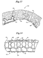
- Figure 13 is a view of the stent of Figure 11 on an unexpanded balloon demonstrating its flexibility in the unexpanded condition;
- Figure 14 is a showing of the stent of Figure 11 expanded on a balloon;
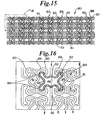
- Figure 15 is a flat plan similar to Figures 1, 5, 8, and 11 showing yet another stent embodiment in the unexpanded condition;
- Figure 16 is a detail view of a portion of Figure 15, as indicated;
- Figure 17 is a showing of the stent of Figure 15 expanded on a balloon;
- Figure 18 is a flat plan similar to Figures 1, 5, 8, 11 and 15 showing still another stent embodiment in the unexpanded condition;
- Figure 19 is a detail view of a portion of Figure 18, as indicated;
- Figure 20 is a flat plan view similar to Figures 1, 5, 8, 11, 15 and 18 showing yet another stent embodiment in the unexpanded condition;
- Figure 21 is a detail view of a portion of Figure 20, and
- Figure 22 is a flat plan view of another embodiment of the invention.
- A preferred embodiment of a generally cylindrical stent 10 according to the invention is illustrated in Figures 1-4. It comprises a metal tube as shown in Figures 2 and 4, such as nitinol or stainless steel preferably, which has been etched or preferably laser cut to the configuration shown in the flat plan view of Figure 1. An enlarged detail of Figure 1 is shown in Figure 3. The configuration is made up of a series of curvilinear expansion cell elements generally indicated at 12 (see darkened example in Figure 3 for clarity) having relatively
wide end portions 14 joined by relativelynarrow center portions 16.Cells 12 are arranged longitudinally as shown in Figure 1 end to end with respect to the longitudinal axis of the stent 10 and in substantially parallel rows as also shown in Figure 1. A plurality of longitudinally extendingelongate support members 18 are included, one each being disposed between adjacent rows ofcells 12. Also, a plurality of circumferentially extendingsupport members 19, preferably substantially normal to supportmembers 18 are also positioned between the rows ofcells 12 to intersect portions of thesupport members 18 and to interconnect them to thenarrow center portions 16 ofcells 12. As can be seen in Figure la,cells 12 may also be arranged in a staggered arrangement. Figures 1b and 1c demonstrate different arrangements and interconnections forcells 12. - When the stent is expanded, as shown in Figure 4, on a
balloon 20 thecells 12 take on a new configuration as shown, the members making up the stent being indicated by the same numbers as used in Figure 1 and Figure 3. Again, one cell is shown darkened for clarity. - Referring now to Figures 5-7, another stent embodiment generally indicated at 22 of the invention is shown. In this embodiment, as seen in Figures 5 and 6,
expansion cells 24, best seen in the detail of Figure 6 and indicated by darkened portion, have relativelywide end portions 26, best seen in Figure 6, andnarrow center portions 28 and are arranged end to end in longitudinal rows as described with respect to the first embodiment.Adjacent end portions 26 are interconnected by pairs of longitudinal support members in the form ofsegments 30 which have curvedend portions 32. Circumferential extendingsegments 34 extend between rows ofcells 24 to interconnect thenarrow center portions 28. - Upon radial expansion of the stent, as on a
balloon 20 for example, its configuration changes by deformation force in the directions shown by the arrows in Figure 6 to that configuration shown in Figure 7. The elements indicated in Figure 7 are identified by the same numbers indicated for similar elements in Figures 5 and 6. - Figures 20 and 21 show a configuration somewhat similar to that of Figures 5-7 but without interconnecting
elements 28. - Referring now to Figures 8-10, another stent embodiment of the invention is shown and generally indicated at 40. Again, as seen in Figures 8 and 9, expansion cells 42 (example darkened for clarity) have relatively
wide end portions 44 andnarrow center portions 46. The end portions include inwardly extendingloop portions 48.Cells 42 are arranged end to end in longitudinal rows as in the preceding embodiments.Adjacent end portions 44 are interconnected by pairs of longitudinalsupport member segments 50 which havecurved end portions 52. Circumferentially extendingsegments 54 extend between rows ofcells 42 to interconnect thenarrow center portions 46 of the cells. Figure 8a shows a variation in shape forcells 42. - Upon radial expansion of the stent upon a
balloon 20, the configuration changes to that shown in Figure 10. The arrows show the direction of force of deformation upon expansion. - Referring now to Figures 11 and 12, still another embodiment of a
stent 60 is shown. Again, as shown in Figures 11 and 12, expansion cells 62 (example darkened for clarity) have relativelywide end portions 64 having a slightinward bend 65 to them andnarrow center portions 66.Cells 62 are arranged end to end in longitudinal rows as in the preceding embodiments.Adjacent end portions 64 are interconnected by pairs of longitudinalsupport member segments 68 which havecurved end portions 70. Circumferentially extendingsegments 72 extend between rows ofcells 62 to interconnect thenarrow center portions 66 of the cells. - Reference to Figure 13 will show the inherent flexibility of the stents of this invention.
- Upon radial expansion of the stent upon a
balloon 20, the configuration changes to that shown in Figure 14. - Referring now to Figures 15 and 16, yet another embodiment of a
stent 80 is shown in a configuration quite similar to that of Figures 11-14 but with an added circumferentially extendingstructural element 81. Again, as best seen in Figure 16, expansion cells 82 (examples darkened for clarity) have relativelywide end portions 84 having a slightinward bend 85 to them andnarrow center portions 86.Cells 82 are arranged end to end in longitudinal rows as in the preceding embodiments.Adjacent end portions 84 are interconnected by pairs of longitudinalsupport member segments 88 which havecurved end portions 90. Circumferentially extendingsegments 92 extend between rows ofcells 82 to interconnect thenarrow center portions 86 of the cells. Circumferentially extendingsegments 81 interconnect pairs ofsupport member segments 88. - Upon radial expansion of the stent on a
balloon 20, the configuration changes to that shown in Figure 17. - Referring now to Figures 18 and 19, still another embodiment of a
stent configuration 100 is shown. As before this embodiment is similar to that of Figures 11-12 except that thecircumferentially extending segments 101 are arranged differently than those identified in Figures 11-12 as 72. In this embodiment thecircumferentially extending members 101 extend between the adjacent ends of adjacent cells 103 (examples darkened for clarity) to interconnect the top of one end to the bottom of the adjacent end and themembers 101 have a slight curve or bend 105 in their length. The other members are all similarly numbered as in the preceding Figures. - Figure 22 shows yet another embodiment of a stent comprised of
cells 120 having interconnectingcircumferential extending members 122. The cells have common sides or endmembers 124 and are arranged in groups to formbands 126 which are interconnected by joinedcells 128. - While this invention may be embodied in many different forms, there are described in detail herein specific preferred embodiments of the invention. This description is an exemplification of the principles of the invention and is not intended to limit the invention to the particular embodiments illustrated.
- The above Examples and disclosure are intended to be illustrative and not exhaustive. These examples and description will suggest many variations and alternatives to one of ordinary skill in this art. All these alternatives and variations are intended to be included within the scope of the attached claims. Those familiar with the art may recognize other equivalents to the specific embodiments described herein which equivalents are also intended to be encompassed by the claims attached hereto.
- Examples of stents are listed below:
- 1. A stent of generally cylindrical shape made up of a plurality of regularly arranged curvilinear bodies of same shape providing closed expansion cells, the cells having relatively wide end portions joined by a relatively narrow center portion and being arranged longitudinally in rows with respect to the longitudinal axis of the stent.
- 2. The stent of
number 1 wherein the curvilinear bodies are also arranged in substantially parallel longitudinal rows end to end and there is included;- a plurality of longitudinal support members positioned between the longitudinal rows of cells, and
- a plurality of circumferentially extending connecting members substantially normal to the support members and interconnecting them to the narrow center portions of the cells.
- 3. The stent of
number 1 wherein the rows of cells are substantially parallel and the cells are in alignment circumferentially. - 4. The stent of number 3 wherein the cells are staggered circumferentially.
- 5. A stent of generally cylindrical shape made up of a plurality of curvilinear bodies providing closed expansion cells, the cells being formed of relatively wide end portions and narrow center portions and being arranged in longitudinal rows around the periphery of the stent and end to end in each row; paired longitudinal connecting members connecting the ends of adjacent cells, and circumferentially extending members extending between cells of adjacent rows and interconnecting the cells at the narrow portions.
- 6. The stent of number 5 including members which extend between adjacent cell ends interconnecting the top of one cell end to the bottom of another.
- 7. A stent of generally cylindrical shape made up of a plurality of regularly arranged closed cell bodies of same shape providing closed expansion cells, the cells having relatively wide end portions joined by a relatively narrow center portion and being arranged longitudinally with respect to the longitudinal axis of the stent.
- 8. The stent of number 7 wherein the bodies are also arranged in substantially parallel longitudinal rows end to end.
- 9. A stent of generally cylindrical shape made up of a plurality of regularly arranged closed cell bodies providing closed expansion cells, the cells having relatively wide end portions joined by a relatively narrow center portion.
Claims (7)
- A stent of generally cylindrical shape comprising a plurality of interconnected cells having relatively wide end portions joined by a narrow center portion and arranged in a staggered arrangement.
- The stent of claim 1 wherein each cell having relatively wide end portions joined by a narrow center portion is connected to an adjacent such cell via a straight, circumferentially extending connector.
- The stent of claim 1 wherein the interconnected cells form helically extending bands of cells having relatively wide end portions joined by a narrow center portion.
- The stent of claim 1 wherein the interconnected cells having relatively wide end portions joined by a narrow center include cells having a longitudinal axis parallel to the longitudinal axis of the stent.
- The stent of claim 1 wherein the interconnected cells having relatively wide end portions joined by a narrow center include cells having a longitudinal axis perpendicular to the longitudinal axis of the stent.
- The stent of claim 1 wherein the interconnected cells having relatively wide end portions joined by a narrow center include cells having a longitudinal axis perpendicular to the longitudinal axis of the stent and cells having a longitudinal axis parallel to the longitudinal axis of the stent.
- A stent comprising a plurality of sections, each section consisting of interconnected hour-glass shaped cells, adjacent sections connected together so as to form sections having both hour-glass shaped cells and non-hour-glass shaped cells.
Applications Claiming Priority (2)
| Application Number | Priority Date | Filing Date | Title |
|---|---|---|---|
| US08/947,620 US6013091A (en) | 1997-10-09 | 1997-10-09 | Stent configurations |
| EP98950972A EP1027012B1 (en) | 1997-10-09 | 1998-10-06 | Improved stent configurations |
Related Parent Applications (1)
| Application Number | Title | Priority Date | Filing Date |
|---|---|---|---|
| EP98950972A Division EP1027012B1 (en) | 1997-10-09 | 1998-10-06 | Improved stent configurations |
Publications (3)
| Publication Number | Publication Date |
|---|---|
| EP1844741A2 true EP1844741A2 (en) | 2007-10-17 |
| EP1844741A3 EP1844741A3 (en) | 2007-10-24 |
| EP1844741B1 EP1844741B1 (en) | 2010-01-06 |
Family
ID=25486437
Family Applications (2)
| Application Number | Title | Priority Date | Filing Date |
|---|---|---|---|
| EP07014258A Expired - Lifetime EP1844741B1 (en) | 1997-10-09 | 1998-10-06 | Improved stent configurations |
| EP98950972A Expired - Lifetime EP1027012B1 (en) | 1997-10-09 | 1998-10-06 | Improved stent configurations |
Family Applications After (1)
| Application Number | Title | Priority Date | Filing Date |
|---|---|---|---|
| EP98950972A Expired - Lifetime EP1027012B1 (en) | 1997-10-09 | 1998-10-06 | Improved stent configurations |
Country Status (8)
| Country | Link |
|---|---|
| US (4) | US6013091A (en) |
| EP (2) | EP1844741B1 (en) |
| JP (1) | JP4271846B2 (en) |
| AT (2) | ATE454114T1 (en) |
| CA (2) | CA2303344C (en) |
| DE (2) | DE69841444D1 (en) |
| ES (1) | ES2335363T3 (en) |
| WO (1) | WO1999018888A1 (en) |
Cited By (1)
| Publication number | Priority date | Publication date | Assignee | Title |
|---|---|---|---|---|
| US8103140B2 (en) | 2009-06-01 | 2012-01-24 | Honeywell International Inc. | Interferometric fiber optic gyroscope with silicon optical bench front-end |
Families Citing this family (141)
| Publication number | Priority date | Publication date | Assignee | Title |
|---|---|---|---|---|
| US7204848B1 (en) | 1995-03-01 | 2007-04-17 | Boston Scientific Scimed, Inc. | Longitudinally flexible expandable stent |
| JP4636634B2 (en) | 1996-04-26 | 2011-02-23 | ボストン サイエンティフィック サイムド,インコーポレイテッド | Intravascular stent |
| US20040106985A1 (en) | 1996-04-26 | 2004-06-03 | Jang G. David | Intravascular stent |
| US6235053B1 (en) | 1998-02-02 | 2001-05-22 | G. David Jang | Tubular stent consists of chevron-shape expansion struts and contralaterally attached diagonal connectors |
| US6325826B1 (en) | 1998-01-14 | 2001-12-04 | Advanced Stent Technologies, Inc. | Extendible stent apparatus |
| US6682536B2 (en) | 2000-03-22 | 2004-01-27 | Advanced Stent Technologies, Inc. | Guidewire introducer sheath |
| US6599316B2 (en) | 1996-11-04 | 2003-07-29 | Advanced Stent Technologies, Inc. | Extendible stent apparatus |
| AU4896797A (en) * | 1996-11-04 | 1998-05-29 | Davidson, Charles | Extendible stent apparatus and method for deploying the same |
| US7591846B2 (en) * | 1996-11-04 | 2009-09-22 | Boston Scientific Scimed, Inc. | Methods for deploying stents in bifurcations |
| US8211167B2 (en) | 1999-12-06 | 2012-07-03 | Boston Scientific Scimed, Inc. | Method of using a catheter with attached flexible side sheath |
| US6835203B1 (en) * | 1996-11-04 | 2004-12-28 | Advanced Stent Technologies, Inc. | Extendible stent apparatus |
| US7341598B2 (en) * | 1999-01-13 | 2008-03-11 | Boston Scientific Scimed, Inc. | Stent with protruding branch portion for bifurcated vessels |
| US7220275B2 (en) * | 1996-11-04 | 2007-05-22 | Advanced Stent Technologies, Inc. | Stent with protruding branch portion for bifurcated vessels |
| US6692483B2 (en) | 1996-11-04 | 2004-02-17 | Advanced Stent Technologies, Inc. | Catheter with attached flexible side sheath |
| GB9703859D0 (en) * | 1997-02-25 | 1997-04-16 | Plante Sylvain | Expandable intravascular stent |
| US20020133222A1 (en) * | 1997-03-05 | 2002-09-19 | Das Gladwin S. | Expandable stent having a plurality of interconnected expansion modules |
| EP0884029B1 (en) * | 1997-06-13 | 2004-12-22 | Gary J. Becker | Expandable intraluminal endoprosthesis |
| US6013091A (en) * | 1997-10-09 | 2000-01-11 | Scimed Life Systems, Inc. | Stent configurations |
| DE69931472T2 (en) | 1998-03-04 | 2006-09-28 | Boston Scientific Ltd., St. Michael | STENT WITH IMPROVED CELL CONFIGURATION |
| US6093203A (en) | 1998-05-13 | 2000-07-25 | Uflacker; Renan | Stent or graft support structure for treating bifurcated vessels having different diameter portions and methods of use and implantation |
| US6461380B1 (en) | 1998-07-28 | 2002-10-08 | Advanced Cardiovascular Systems, Inc. | Stent configuration |
| US6193744B1 (en) * | 1998-09-10 | 2001-02-27 | Scimed Life Systems, Inc. | Stent configurations |
| US8382821B2 (en) | 1998-12-03 | 2013-02-26 | Medinol Ltd. | Helical hybrid stent |
| US20060122691A1 (en) * | 1998-12-03 | 2006-06-08 | Jacob Richter | Hybrid stent |
| US20060178727A1 (en) * | 1998-12-03 | 2006-08-10 | Jacob Richter | Hybrid amorphous metal alloy stent |
| US20050033399A1 (en) * | 1998-12-03 | 2005-02-10 | Jacob Richter | Hybrid stent |
| US20070219642A1 (en) * | 1998-12-03 | 2007-09-20 | Jacob Richter | Hybrid stent having a fiber or wire backbone |
| US6743252B1 (en) * | 1998-12-18 | 2004-06-01 | Cook Incorporated | Cannula stent |
| US7655030B2 (en) | 2003-07-18 | 2010-02-02 | Boston Scientific Scimed, Inc. | Catheter balloon systems and methods |
| US20050060027A1 (en) * | 1999-01-13 | 2005-03-17 | Advanced Stent Technologies, Inc. | Catheter balloon systems and methods |
| US6368346B1 (en) | 1999-06-03 | 2002-04-09 | American Medical Systems, Inc. | Bioresorbable stent |
| US7387639B2 (en) * | 1999-06-04 | 2008-06-17 | Advanced Stent Technologies, Inc. | Short sleeve stent delivery catheter and methods |
| US6689156B1 (en) | 1999-09-23 | 2004-02-10 | Advanced Stent Technologies, Inc. | Stent range transducers and methods of use |
| CN1409622A (en) * | 1999-09-23 | 2003-04-09 | 先进扩张技术公司 | Bifurcation stent system and method |
| US20010047200A1 (en) * | 1999-10-13 | 2001-11-29 | Raymond Sun | Non-foreshortening intraluminal prosthesis |
| US6679910B1 (en) * | 1999-11-12 | 2004-01-20 | Latin American Devices Llc | Intraluminal stent |
| DE19957063A1 (en) * | 1999-11-26 | 2001-08-02 | Franz Herbst | Stent and method for its manufacture |
| AU2428201A (en) * | 1999-12-07 | 2001-06-18 | Edwards Lifesciences Corporation | Novel enhanced flexible expandable stents |
| US6723119B2 (en) * | 2000-03-01 | 2004-04-20 | Medinol Ltd. | Longitudinally flexible stent |
| US8496699B2 (en) * | 2000-03-01 | 2013-07-30 | Medinol Ltd. | Longitudinally flexible stent |
| US7758627B2 (en) * | 2000-03-01 | 2010-07-20 | Medinol, Ltd. | Longitudinally flexible stent |
| SG86458A1 (en) | 2000-03-01 | 2002-02-19 | Medinol Ltd | Longitudinally flexible stent |
| US8920487B1 (en) | 2000-03-01 | 2014-12-30 | Medinol Ltd. | Longitudinally flexible stent |
| US8202312B2 (en) * | 2000-03-01 | 2012-06-19 | Medinol Ltd. | Longitudinally flexible stent |
| US7621947B2 (en) | 2000-03-01 | 2009-11-24 | Medinol, Ltd. | Longitudinally flexible stent |
| US7141062B1 (en) * | 2000-03-01 | 2006-11-28 | Medinol, Ltd. | Longitudinally flexible stent |
| US7828835B2 (en) | 2000-03-01 | 2010-11-09 | Medinol Ltd. | Longitudinally flexible stent |
| DE10012460A1 (en) * | 2000-03-15 | 2001-09-20 | Biotronik Mess & Therapieg | Stent consists of several adjacent lengthwise tubular sections joined by first and second connections consisting of cell-type elements of one orientation. |
| US6616689B1 (en) | 2000-05-03 | 2003-09-09 | Advanced Cardiovascular Systems, Inc. | Intravascular stent |
| US6440162B1 (en) | 2000-07-26 | 2002-08-27 | Advanced Cardiovascular Systems, Inc. | Stent having increased scaffolding expandable bar arms |
| WO2002015821A1 (en) * | 2000-08-24 | 2002-02-28 | Stenttech, Inc. Dba Stenttech | Expandable stent having a plurality of expansion cell modules |
| US7766956B2 (en) | 2000-09-22 | 2010-08-03 | Boston Scientific Scimed, Inc. | Intravascular stent and assembly |
| US6485508B1 (en) * | 2000-10-13 | 2002-11-26 | Mcguinness Colm P. | Low profile stent |
| US6506211B1 (en) * | 2000-11-13 | 2003-01-14 | Scimed Life Systems, Inc. | Stent designs |
| US6929660B1 (en) * | 2000-12-22 | 2005-08-16 | Advanced Cardiovascular Systems, Inc. | Intravascular stent |
| US8617231B2 (en) | 2001-05-18 | 2013-12-31 | Boston Scientific Scimed, Inc. | Dual guidewire exchange catheter system |
| US20020188342A1 (en) * | 2001-06-01 | 2002-12-12 | Rykhus Robert L. | Short-term bioresorbable stents |
| US6887215B2 (en) | 2001-06-01 | 2005-05-03 | Boston Scientific Scimed, Inc. | Compressible ureteral stent for comfort |
| US20030069629A1 (en) * | 2001-06-01 | 2003-04-10 | Jadhav Balkrishna S. | Bioresorbable medical devices |
| US6939373B2 (en) * | 2003-08-20 | 2005-09-06 | Advanced Cardiovascular Systems, Inc. | Intravascular stent |
| US6629994B2 (en) * | 2001-06-11 | 2003-10-07 | Advanced Cardiovascular Systems, Inc. | Intravascular stent |
| US6635083B1 (en) | 2001-06-25 | 2003-10-21 | Advanced Cardiovascular Systems, Inc. | Stent with non-linear links and method of use |
| US6749629B1 (en) | 2001-06-27 | 2004-06-15 | Advanced Cardiovascular Systems, Inc. | Stent pattern with figure-eights |
| IES20010828A2 (en) * | 2001-09-12 | 2003-03-19 | Medtronic Inc | Medical device for intraluminal endovascular stenting |
| US7537607B2 (en) * | 2001-12-21 | 2009-05-26 | Boston Scientific Scimed, Inc. | Stent geometry for improved flexibility |
| EP1495625B1 (en) * | 2002-04-02 | 2011-09-28 | Verizon Business Global LLC | Providing of presence information to a telephony services system |
| EP2529707B1 (en) * | 2002-05-08 | 2015-04-15 | Abbott Laboratories | Endoprosthesis having foot extensions |
| US6656220B1 (en) | 2002-06-17 | 2003-12-02 | Advanced Cardiovascular Systems, Inc. | Intravascular stent |
| DE10228529A1 (en) * | 2002-06-26 | 2004-01-22 | Admedes Schuessler Gmbh | stent |
| US20050065596A1 (en) * | 2002-07-24 | 2005-03-24 | Xufan Tseng | Stents capable of controllably releasing histone deacetylase inhibitors |
| US7485139B1 (en) | 2002-10-10 | 2009-02-03 | Ciamacco Jr Sam | Stent delivery and deployment system |
| US7959671B2 (en) | 2002-11-05 | 2011-06-14 | Merit Medical Systems, Inc. | Differential covering and coating methods |
| US7637942B2 (en) | 2002-11-05 | 2009-12-29 | Merit Medical Systems, Inc. | Coated stent with geometry determinated functionality and method of making the same |
| US7875068B2 (en) | 2002-11-05 | 2011-01-25 | Merit Medical Systems, Inc. | Removable biliary stent |
| DE10253633B4 (en) * | 2002-11-13 | 2011-08-11 | BIOTRONIK GmbH & Co. KG, 12359 | supporting structure |
| US7172624B2 (en) * | 2003-02-06 | 2007-02-06 | Boston Scientific Scimed, Inc. | Medical device with magnetic resonance visibility enhancing structure |
| US7179286B2 (en) * | 2003-02-21 | 2007-02-20 | Boston Scientific Scimed, Inc. | Stent with stepped connectors |
| US20040181186A1 (en) * | 2003-03-13 | 2004-09-16 | Scimed Life Systems, Inc. | Medical device |
| US7625401B2 (en) * | 2003-05-06 | 2009-12-01 | Abbott Laboratories | Endoprosthesis having foot extensions |
| US7625398B2 (en) * | 2003-05-06 | 2009-12-01 | Abbott Laboratories | Endoprosthesis having foot extensions |
| US7131993B2 (en) * | 2003-06-25 | 2006-11-07 | Boston Scientific Scimed, Inc. | Varying circumferential spanned connectors in a stent |
| US9155639B2 (en) * | 2009-04-22 | 2015-10-13 | Medinol Ltd. | Helical hybrid stent |
| US9039755B2 (en) | 2003-06-27 | 2015-05-26 | Medinol Ltd. | Helical hybrid stent |
| US8298280B2 (en) * | 2003-08-21 | 2012-10-30 | Boston Scientific Scimed, Inc. | Stent with protruding branch portion for bifurcated vessels |
| US7344557B2 (en) * | 2003-11-12 | 2008-03-18 | Advanced Stent Technologies, Inc. | Catheter balloon systems and methods |
| GB0402103D0 (en) * | 2004-02-02 | 2004-03-03 | Hengelmolen Rudy | Tubular graft |
| US7763064B2 (en) * | 2004-06-08 | 2010-07-27 | Medinol, Ltd. | Stent having struts with reverse direction curvature |
| CA2559540A1 (en) * | 2004-06-08 | 2005-12-29 | Advanced Stent Technologies, Inc. | Stent with protruding branch portion for bifurcated vessels |
| US20070292478A1 (en) | 2004-08-30 | 2007-12-20 | Popowski Youri | Medical Implant Provided with Inhibitors of Atp Synthesis |
| US9427340B2 (en) * | 2004-12-14 | 2016-08-30 | Boston Scientific Scimed, Inc. | Stent with protruding branch portion for bifurcated vessels |
| US8317855B2 (en) * | 2005-05-26 | 2012-11-27 | Boston Scientific Scimed, Inc. | Crimpable and expandable side branch cell |
| EP2364676B1 (en) | 2005-06-30 | 2018-12-19 | Abbott Laboratories | Endoprosthesis having foot extensions |
| US8038706B2 (en) * | 2005-09-08 | 2011-10-18 | Boston Scientific Scimed, Inc. | Crown stent assembly |
| US20070112418A1 (en) | 2005-11-14 | 2007-05-17 | Boston Scientific Scimed, Inc. | Stent with spiral side-branch support designs |
| US8435284B2 (en) * | 2005-12-14 | 2013-05-07 | Boston Scientific Scimed, Inc. | Telescoping bifurcated stent |
| US8343211B2 (en) * | 2005-12-14 | 2013-01-01 | Boston Scientific Scimed, Inc. | Connectors for bifurcated stent |
| US20070142904A1 (en) * | 2005-12-20 | 2007-06-21 | Boston Scientific Scimed, Inc. | Bifurcated stent with multiple locations for side branch access |
| US7540881B2 (en) * | 2005-12-22 | 2009-06-02 | Boston Scientific Scimed, Inc. | Bifurcation stent pattern |
| US20070191926A1 (en) * | 2006-02-14 | 2007-08-16 | Advanced Cardiovascular Systems, Inc. | Stent pattern for high stent retention |
| US8821561B2 (en) * | 2006-02-22 | 2014-09-02 | Boston Scientific Scimed, Inc. | Marker arrangement for bifurcation catheter |
| US7833264B2 (en) * | 2006-03-06 | 2010-11-16 | Boston Scientific Scimed, Inc. | Bifurcated stent |
| US20070208419A1 (en) * | 2006-03-06 | 2007-09-06 | Boston Scientific Scimed, Inc. | Bifurcation stent with uniform side branch projection |
| US8298278B2 (en) * | 2006-03-07 | 2012-10-30 | Boston Scientific Scimed, Inc. | Bifurcated stent with improvement securement |
| US8043358B2 (en) * | 2006-03-29 | 2011-10-25 | Boston Scientific Scimed, Inc. | Stent with overlap and high extension |
| US8348991B2 (en) * | 2006-03-29 | 2013-01-08 | Boston Scientific Scimed, Inc. | Stent with overlap and high expansion |
| US7744643B2 (en) | 2006-05-04 | 2010-06-29 | Boston Scientific Scimed, Inc. | Displaceable stent side branch structure |
| US8460364B2 (en) * | 2006-07-20 | 2013-06-11 | Orbusneich Medical, Inc. | Bioabsorbable polymeric medical device |
| US7988720B2 (en) | 2006-09-12 | 2011-08-02 | Boston Scientific Scimed, Inc. | Longitudinally flexible expandable stent |
| US8778009B2 (en) * | 2006-10-06 | 2014-07-15 | Abbott Cardiovascular Systems Inc. | Intravascular stent |
| US7951191B2 (en) * | 2006-10-10 | 2011-05-31 | Boston Scientific Scimed, Inc. | Bifurcated stent with entire circumferential petal |
| US7842082B2 (en) | 2006-11-16 | 2010-11-30 | Boston Scientific Scimed, Inc. | Bifurcated stent |
| US8118861B2 (en) | 2007-03-28 | 2012-02-21 | Boston Scientific Scimed, Inc. | Bifurcation stent and balloon assemblies |
| US8486134B2 (en) | 2007-08-01 | 2013-07-16 | Boston Scientific Scimed, Inc. | Bifurcation treatment system and methods |
| US7959669B2 (en) | 2007-09-12 | 2011-06-14 | Boston Scientific Scimed, Inc. | Bifurcated stent with open ended side branch support |
| US8066755B2 (en) | 2007-09-26 | 2011-11-29 | Trivascular, Inc. | System and method of pivoted stent deployment |
| US8226701B2 (en) | 2007-09-26 | 2012-07-24 | Trivascular, Inc. | Stent and delivery system for deployment thereof |
| US8663309B2 (en) | 2007-09-26 | 2014-03-04 | Trivascular, Inc. | Asymmetric stent apparatus and method |
| CN101917929A (en) | 2007-10-04 | 2010-12-15 | 特里瓦斯库拉尔公司 | Modular vascular graft for low profile percutaneous delivery |
| US8936567B2 (en) * | 2007-11-14 | 2015-01-20 | Boston Scientific Scimed, Inc. | Balloon bifurcated lumen treatment |
| US8083789B2 (en) | 2007-11-16 | 2011-12-27 | Trivascular, Inc. | Securement assembly and method for expandable endovascular device |
| US8328861B2 (en) | 2007-11-16 | 2012-12-11 | Trivascular, Inc. | Delivery system and method for bifurcated graft |
| US7833266B2 (en) | 2007-11-28 | 2010-11-16 | Boston Scientific Scimed, Inc. | Bifurcated stent with drug wells for specific ostial, carina, and side branch treatment |
| US8277501B2 (en) * | 2007-12-21 | 2012-10-02 | Boston Scientific Scimed, Inc. | Bi-stable bifurcated stent petal geometry |
| WO2009088953A2 (en) * | 2007-12-31 | 2009-07-16 | Boston Scientific Scimed Inc. | Bifurcation stent delivery system and methods |
| US20090240318A1 (en) * | 2008-03-19 | 2009-09-24 | Boston Scientific Scimed, Inc. | Stent expansion column, strut and connector slit design |
| US8531024B2 (en) * | 2008-03-25 | 2013-09-10 | Bridge Semiconductor Corporation | Semiconductor chip assembly with post/base heat spreader and multilevel conductive trace |
| US8932340B2 (en) | 2008-05-29 | 2015-01-13 | Boston Scientific Scimed, Inc. | Bifurcated stent and delivery system |
| US8377108B2 (en) | 2008-06-02 | 2013-02-19 | Boston Scientific Scimed, Inc. | Staggered two balloon bifurcation catheter assembly and methods |
| JP5662310B2 (en) * | 2008-06-05 | 2015-01-28 | ボストン サイエンティフィック サイムド,インコーポレイテッドBoston Scientific Scimed,Inc. | Shrinkable branch device and method of manufacturing the same |
| WO2010042854A1 (en) * | 2008-10-10 | 2010-04-15 | Orbusneich Medical, Inc. | Bioabsorbable polymeric medical device |
| EP2552356B1 (en) * | 2010-03-26 | 2019-03-13 | Thubrikar Aortic Valve Inc. | Valve component, frame component and prosthetic valve device including the same for implantation in a body lumen |
| US8858615B2 (en) * | 2010-05-19 | 2014-10-14 | National Taiwan University | Preventing vascular stenosis of cardiovascular stent |
| ES2374382B2 (en) * | 2011-10-27 | 2012-12-05 | Javier Gallastegui Goiburu | STENT |
| US8992595B2 (en) | 2012-04-04 | 2015-03-31 | Trivascular, Inc. | Durable stent graft with tapered struts and stable delivery methods and devices |
| US9498363B2 (en) | 2012-04-06 | 2016-11-22 | Trivascular, Inc. | Delivery catheter for endovascular device |
| BR112014028242B1 (en) | 2012-05-14 | 2021-04-13 | C.R. Bard, Inc | INTRALUMINAL PROSTHESIS |
| USD723165S1 (en) | 2013-03-12 | 2015-02-24 | C. R. Bard, Inc. | Stent |
| US9381103B2 (en) * | 2014-10-06 | 2016-07-05 | Abbott Cardiovascular Systems Inc. | Stent with elongating struts |
| US10905578B2 (en) | 2017-02-02 | 2021-02-02 | C. R. Bard, Inc. | Short stent |
| US10238513B2 (en) | 2017-07-19 | 2019-03-26 | Abbott Cardiovascular Systems Inc. | Intravascular stent |
| CN108969165B (en) * | 2018-06-13 | 2020-08-07 | 哈尔滨工业大学 | 4D printing shape memory polymer composite material tracheal stent and preparation method thereof |
Citations (3)
| Publication number | Priority date | Publication date | Assignee | Title |
|---|---|---|---|---|
| WO1997033534A1 (en) * | 1996-03-13 | 1997-09-18 | Medtronic, Inc. | Radiopaque stent markers |
| EP0875215A1 (en) * | 1997-04-29 | 1998-11-04 | SORIN BIOMEDICA CARDIO S.p.A. | "A stent for angioplasty" |
| EP0893107A1 (en) * | 1996-02-21 | 1999-01-27 | Robert E. Fischell | Expandable stent |
Family Cites Families (55)
| Publication number | Priority date | Publication date | Assignee | Title |
|---|---|---|---|---|
| US5102417A (en) * | 1985-11-07 | 1992-04-07 | Expandable Grafts Partnership | Expandable intraluminal graft, and method and apparatus for implanting an expandable intraluminal graft |
| US5133732A (en) * | 1987-10-19 | 1992-07-28 | Medtronic, Inc. | Intravascular stent |
| JPH04283885A (en) * | 1991-03-13 | 1992-10-08 | Alps Electric Co Ltd | Automatic identification decoder |
| CA2079417C (en) * | 1991-10-28 | 2003-01-07 | Lilip Lau | Expandable stents and method of making same |
| DE4306431C2 (en) * | 1993-03-02 | 2000-04-20 | Hengst Walter Gmbh & Co Kg | Device for separating contaminants from the lubricating oil of an internal combustion engine |
| GB2281865B (en) | 1993-09-16 | 1997-07-30 | Cordis Corp | Endoprosthesis having multiple laser welded junctions,method and procedure |
| FR2710834B1 (en) * | 1993-10-05 | 1995-12-22 | Guerbet Sa | Expandable tubular organ for intraluminal endoprosthesis, intraluminal endoprosthesis, manufacturing process. |
| JP2703510B2 (en) * | 1993-12-28 | 1998-01-26 | アドヴァンスド カーディオヴァスキュラー システムズ インコーポレーテッド | Expandable stent and method of manufacturing the same |
| US5733303A (en) * | 1994-03-17 | 1998-03-31 | Medinol Ltd. | Flexible expandable stent |
| US5449373A (en) * | 1994-03-17 | 1995-09-12 | Medinol Ltd. | Articulated stent |
| US5630829A (en) * | 1994-12-09 | 1997-05-20 | Intervascular, Inc. | High hoop strength intraluminal stent |
| US5591226A (en) * | 1995-01-23 | 1997-01-07 | Schneider (Usa) Inc. | Percutaneous stent-graft and method for delivery thereof |
| DE69637527D1 (en) * | 1995-03-01 | 2008-06-26 | Boston Scient Scimed Inc | Longitudinally flexible and expandable stent |
| US5591197A (en) * | 1995-03-14 | 1997-01-07 | Advanced Cardiovascular Systems, Inc. | Expandable stent forming projecting barbs and method for deploying |
| EP0734698B9 (en) * | 1995-04-01 | 2006-07-05 | Variomed AG | Stent for transluminal implantation into hollow organs |
| HU221910B1 (en) * | 1995-07-25 | 2003-02-28 | Medstent Inc. | Expandible stent |
| US5894406A (en) * | 1995-09-05 | 1999-04-13 | Blend; Michael L. | Elevated separate external keyboard apparatus for use with portable computer |
| US5776161A (en) * | 1995-10-16 | 1998-07-07 | Instent, Inc. | Medical stents, apparatus and method for making same |
| WO1997014375A1 (en) * | 1995-10-20 | 1997-04-24 | Bandula Wijay | Vascular stent |
| US6203569B1 (en) * | 1996-01-04 | 2001-03-20 | Bandula Wijay | Flexible stent |
| WO1997025937A1 (en) | 1996-01-18 | 1997-07-24 | Jang G David | Programmable variably flexible modular stents |
| US5895406A (en) * | 1996-01-26 | 1999-04-20 | Cordis Corporation | Axially flexible stent |
| DE29615969U1 (en) * | 1996-02-29 | 1996-10-31 | Medinol Ltd | Stent |
| CA2192520A1 (en) * | 1996-03-05 | 1997-09-05 | Ian M. Penn | Expandable stent and method for delivery of same |
| CA2248718A1 (en) * | 1996-03-05 | 1997-09-12 | Divysio Solutions Ulc. | Expandable stent and method for delivery of same |
| DE19614160A1 (en) * | 1996-04-10 | 1997-10-16 | Variomed Ag | Stent for transluminal implantation in hollow organs |
| US5922021A (en) * | 1996-04-26 | 1999-07-13 | Jang; G. David | Intravascular stent |
| US5669932A (en) * | 1996-05-29 | 1997-09-23 | Isostent, Inc. | Means for accurately positioning an expandable stent |
| US5697971A (en) * | 1996-06-11 | 1997-12-16 | Fischell; Robert E. | Multi-cell stent with cells having differing characteristics |
| US5755776A (en) | 1996-10-04 | 1998-05-26 | Al-Saadon; Khalid | Permanent expandable intraluminal tubular stent |
| EP0884985B1 (en) | 1996-10-28 | 2003-06-25 | BIOTRONIK Mess- und Therapiegeräte GmbH & Co Ingenieurbüro Berlin | Stent |
| WO1998018405A1 (en) | 1996-10-28 | 1998-05-07 | Biotronik Mess- Und Therapiegeräte Gmbh & Co. | Expandable interluminal device |
| WO1998020810A1 (en) | 1996-11-12 | 1998-05-22 | Medtronic, Inc. | Flexible, radially expansible luminal prostheses |
| JP4188431B2 (en) | 1996-11-29 | 2008-11-26 | 株式会社パイオラックス | Stent |
| JP3798090B2 (en) | 1996-12-06 | 2006-07-19 | 株式会社パイオラックス | Stent |
| JP3519565B2 (en) | 1997-01-24 | 2004-04-19 | 株式会社パイオラックス | Stent |
| DE29701758U1 (en) * | 1997-02-01 | 1997-03-27 | Jomed Implantate Gmbh | Radially expandable stent for implantation in a body vessel, particularly in the area of a vascular branch |
| US5827321A (en) | 1997-02-07 | 1998-10-27 | Cornerstone Devices, Inc. | Non-Foreshortening intraluminal prosthesis |
| DE29702671U1 (en) * | 1997-02-17 | 1997-04-10 | Jomed Implantate Gmbh | Stent |
| US5810872A (en) | 1997-03-14 | 1998-09-22 | Kanesaka; Nozomu | Flexible stent |
| US5718713A (en) | 1997-04-10 | 1998-02-17 | Global Therapeutics, Inc. | Surgical stent having a streamlined contour |
| US5741327A (en) * | 1997-05-06 | 1998-04-21 | Global Therapeutics, Inc. | Surgical stent featuring radiopaque markers |
| DE29708689U1 (en) * | 1997-05-15 | 1997-07-17 | Jomed Implantate Gmbh | Coronary stent |
| DE29708879U1 (en) * | 1997-05-20 | 1997-07-31 | Jomed Implantate Gmbh | Coronary stent |
| EP0884029B1 (en) * | 1997-06-13 | 2004-12-22 | Gary J. Becker | Expandable intraluminal endoprosthesis |
| EP0890346A1 (en) * | 1997-06-13 | 1999-01-13 | Gary J. Becker | Expandable intraluminal endoprosthesis |
| DE29716476U1 (en) | 1997-09-13 | 1997-12-18 | Convent Gerd | Stenosis treatment stent |
| US6013091A (en) | 1997-10-09 | 2000-01-11 | Scimed Life Systems, Inc. | Stent configurations |
| DE69931472T2 (en) * | 1998-03-04 | 2006-09-28 | Boston Scientific Ltd., St. Michael | STENT WITH IMPROVED CELL CONFIGURATION |
| US5935162A (en) * | 1998-03-16 | 1999-08-10 | Medtronic, Inc. | Wire-tubular hybrid stent |
| US6042597A (en) * | 1998-10-23 | 2000-03-28 | Scimed Life Systems, Inc. | Helical stent design |
| EP1469794B1 (en) * | 2002-01-28 | 2009-03-18 | OrbusNeich Medical, Inc. | Flared ostial endoprosthesis and delivery system |
| EP2529707B1 (en) * | 2002-05-08 | 2015-04-15 | Abbott Laboratories | Endoprosthesis having foot extensions |
| US7625401B2 (en) * | 2003-05-06 | 2009-12-01 | Abbott Laboratories | Endoprosthesis having foot extensions |
| US7625398B2 (en) * | 2003-05-06 | 2009-12-01 | Abbott Laboratories | Endoprosthesis having foot extensions |
-
1997
- 1997-10-09 US US08/947,620 patent/US6013091A/en not_active Expired - Lifetime
-
1998
- 1998-10-06 EP EP07014258A patent/EP1844741B1/en not_active Expired - Lifetime
- 1998-10-06 DE DE69841444T patent/DE69841444D1/en not_active Expired - Lifetime
- 1998-10-06 CA CA002303344A patent/CA2303344C/en not_active Expired - Fee Related
- 1998-10-06 DE DE69838428T patent/DE69838428T2/en not_active Expired - Lifetime
- 1998-10-06 WO PCT/US1998/021106 patent/WO1999018888A1/en active IP Right Grant
- 1998-10-06 JP JP2000515529A patent/JP4271846B2/en not_active Expired - Lifetime
- 1998-10-06 EP EP98950972A patent/EP1027012B1/en not_active Expired - Lifetime
- 1998-10-06 AT AT07014258T patent/ATE454114T1/en not_active IP Right Cessation
- 1998-10-06 ES ES07014258T patent/ES2335363T3/en not_active Expired - Lifetime
- 1998-10-06 CA CA2592831A patent/CA2592831C/en not_active Expired - Fee Related
- 1998-10-06 AT AT98950972T patent/ATE372746T1/en not_active IP Right Cessation
-
1999
- 1999-05-21 US US09/316,827 patent/US6416538B1/en not_active Expired - Lifetime
-
2002
- 2002-05-31 US US10/160,494 patent/US7335225B2/en not_active Expired - Fee Related
-
2008
- 2008-02-25 US US12/036,559 patent/US7951187B2/en not_active Expired - Fee Related
Patent Citations (3)
| Publication number | Priority date | Publication date | Assignee | Title |
|---|---|---|---|---|
| EP0893107A1 (en) * | 1996-02-21 | 1999-01-27 | Robert E. Fischell | Expandable stent |
| WO1997033534A1 (en) * | 1996-03-13 | 1997-09-18 | Medtronic, Inc. | Radiopaque stent markers |
| EP0875215A1 (en) * | 1997-04-29 | 1998-11-04 | SORIN BIOMEDICA CARDIO S.p.A. | "A stent for angioplasty" |
Cited By (1)
| Publication number | Priority date | Publication date | Assignee | Title |
|---|---|---|---|---|
| US8103140B2 (en) | 2009-06-01 | 2012-01-24 | Honeywell International Inc. | Interferometric fiber optic gyroscope with silicon optical bench front-end |
Also Published As
| Publication number | Publication date |
|---|---|
| US20020151962A1 (en) | 2002-10-17 |
| US7335225B2 (en) | 2008-02-26 |
| CA2303344C (en) | 2007-08-21 |
| ES2335363T3 (en) | 2010-03-25 |
| ATE372746T1 (en) | 2007-09-15 |
| JP4271846B2 (en) | 2009-06-03 |
| ATE454114T1 (en) | 2010-01-15 |
| EP1844741A3 (en) | 2007-10-24 |
| US20080167706A1 (en) | 2008-07-10 |
| DE69841444D1 (en) | 2010-02-25 |
| WO1999018888A9 (en) | 1999-07-01 |
| WO1999018888A1 (en) | 1999-04-22 |
| EP1027012B1 (en) | 2007-09-12 |
| DE69838428D1 (en) | 2007-10-25 |
| US7951187B2 (en) | 2011-05-31 |
| CA2303344A1 (en) | 1999-04-22 |
| CA2592831C (en) | 2010-04-13 |
| EP1027012A1 (en) | 2000-08-16 |
| DE69838428T2 (en) | 2008-01-17 |
| US6416538B1 (en) | 2002-07-09 |
| EP1844741B1 (en) | 2010-01-06 |
| CA2592831A1 (en) | 1999-04-22 |
| US6013091A (en) | 2000-01-11 |
| JP2001519204A (en) | 2001-10-23 |
Similar Documents
| Publication | Publication Date | Title |
|---|---|---|
| EP1844741A2 (en) | Improved stent configurations | |
| US6033433A (en) | Stent configurations including spirals | |
| US7988718B2 (en) | Stent configurations | |
| EP1819300B1 (en) | Stent having phased hoop sections | |
| EP1295575B1 (en) | Longitudinally flexible stent | |
| EP1796588B1 (en) | Optimized flex link for expandable stent | |
| US6348065B1 (en) | Longitudinally flexible expandable stent | |
| US20010007955A1 (en) | Intravascular hinge stent | |
| GB2369062A (en) | Extendable stent | |
| AU2012202185B2 (en) | Stent having phased hoop sections |
Legal Events
| Date | Code | Title | Description |
|---|---|---|---|
| PUAI | Public reference made under article 153(3) epc to a published international application that has entered the european phase |
Free format text: ORIGINAL CODE: 0009012 |
|
| PUAL | Search report despatched |
Free format text: ORIGINAL CODE: 0009013 |
|
| AC | Divisional application: reference to earlier application |
Ref document number: 1027012 Country of ref document: EP Kind code of ref document: P |
|
| AK | Designated contracting states |
Kind code of ref document: A2 Designated state(s): AT BE CH CY DE DK ES FI FR GB GR IE IT LI LU MC NL PT SE |
|
| AK | Designated contracting states |
Kind code of ref document: A3 Designated state(s): AT BE CH CY DE DK ES FI FR GB GR IE IT LI LU MC NL PT SE |
|
| 17P | Request for examination filed |
Effective date: 20071030 |
|
| 17Q | First examination report despatched |
Effective date: 20071213 |
|
| AKX | Designation fees paid |
Designated state(s): AT BE CH CY DE DK ES FI FR GB GR IE IT LI LU MC NL PT SE |
|
| GRAP | Despatch of communication of intention to grant a patent |
Free format text: ORIGINAL CODE: EPIDOSNIGR1 |
|
| RIN1 | Information on inventor provided before grant (corrected) |
Inventor name: BROWN, BRIAN J. Inventor name: FRIESEN, DAVID L. Inventor name: EHR, TIMOTHY G. J. Inventor name: LEY, TIMOTHY J. Inventor name: KVEEN, GRAIG L. |
|
| GRAS | Grant fee paid |
Free format text: ORIGINAL CODE: EPIDOSNIGR3 |
|
| GRAA | (expected) grant |
Free format text: ORIGINAL CODE: 0009210 |
|
| AC | Divisional application: reference to earlier application |
Ref document number: 1027012 Country of ref document: EP Kind code of ref document: P |
|
| AK | Designated contracting states |
Kind code of ref document: B1 Designated state(s): AT BE CH CY DE DK ES FI FR GB GR IE IT LI LU MC NL PT SE |
|
| REG | Reference to a national code |
Ref country code: GB Ref legal event code: FG4D |
|
| REG | Reference to a national code |
Ref country code: CH Ref legal event code: EP |
|
| REG | Reference to a national code |
Ref country code: IE Ref legal event code: FG4D |
|
| REF | Corresponds to: |
Ref document number: 69841444 Country of ref document: DE Date of ref document: 20100225 Kind code of ref document: P |
|
| REG | Reference to a national code |
Ref country code: ES Ref legal event code: FG2A Ref document number: 2335363 Country of ref document: ES Kind code of ref document: T3 |
|
| REG | Reference to a national code |
Ref country code: NL Ref legal event code: T3 |
|
| PG25 | Lapsed in a contracting state [announced via postgrant information from national office to epo] |
Ref country code: AT Free format text: LAPSE BECAUSE OF FAILURE TO SUBMIT A TRANSLATION OF THE DESCRIPTION OR TO PAY THE FEE WITHIN THE PRESCRIBED TIME-LIMIT Effective date: 20100106 |
|
| PG25 | Lapsed in a contracting state [announced via postgrant information from national office to epo] |
Ref country code: PT Free format text: LAPSE BECAUSE OF FAILURE TO SUBMIT A TRANSLATION OF THE DESCRIPTION OR TO PAY THE FEE WITHIN THE PRESCRIBED TIME-LIMIT Effective date: 20100506 |
|
| PG25 | Lapsed in a contracting state [announced via postgrant information from national office to epo] |
Ref country code: FI Free format text: LAPSE BECAUSE OF FAILURE TO SUBMIT A TRANSLATION OF THE DESCRIPTION OR TO PAY THE FEE WITHIN THE PRESCRIBED TIME-LIMIT Effective date: 20100106 |
|
| PG25 | Lapsed in a contracting state [announced via postgrant information from national office to epo] |
Ref country code: SE Free format text: LAPSE BECAUSE OF FAILURE TO SUBMIT A TRANSLATION OF THE DESCRIPTION OR TO PAY THE FEE WITHIN THE PRESCRIBED TIME-LIMIT Effective date: 20100106 Ref country code: CY Free format text: LAPSE BECAUSE OF FAILURE TO SUBMIT A TRANSLATION OF THE DESCRIPTION OR TO PAY THE FEE WITHIN THE PRESCRIBED TIME-LIMIT Effective date: 20100106 Ref country code: BE Free format text: LAPSE BECAUSE OF FAILURE TO SUBMIT A TRANSLATION OF THE DESCRIPTION OR TO PAY THE FEE WITHIN THE PRESCRIBED TIME-LIMIT Effective date: 20100106 Ref country code: GR Free format text: LAPSE BECAUSE OF FAILURE TO SUBMIT A TRANSLATION OF THE DESCRIPTION OR TO PAY THE FEE WITHIN THE PRESCRIBED TIME-LIMIT Effective date: 20100407 |
|
| PLBE | No opposition filed within time limit |
Free format text: ORIGINAL CODE: 0009261 |
|
| STAA | Information on the status of an ep patent application or granted ep patent |
Free format text: STATUS: NO OPPOSITION FILED WITHIN TIME LIMIT |
|
| 26N | No opposition filed |
Effective date: 20101007 |
|
| PG25 | Lapsed in a contracting state [announced via postgrant information from national office to epo] |
Ref country code: DK Free format text: LAPSE BECAUSE OF FAILURE TO SUBMIT A TRANSLATION OF THE DESCRIPTION OR TO PAY THE FEE WITHIN THE PRESCRIBED TIME-LIMIT Effective date: 20100106 |
|
| PGFP | Annual fee paid to national office [announced via postgrant information from national office to epo] |
Ref country code: IT Payment date: 20101030 Year of fee payment: 13 |
|
| PG25 | Lapsed in a contracting state [announced via postgrant information from national office to epo] |
Ref country code: MC Free format text: LAPSE BECAUSE OF NON-PAYMENT OF DUE FEES Effective date: 20101031 |
|
| REG | Reference to a national code |
Ref country code: CH Ref legal event code: PL |
|
| PG25 | Lapsed in a contracting state [announced via postgrant information from national office to epo] |
Ref country code: LI Free format text: LAPSE BECAUSE OF NON-PAYMENT OF DUE FEES Effective date: 20101031 Ref country code: CH Free format text: LAPSE BECAUSE OF NON-PAYMENT OF DUE FEES Effective date: 20101031 |
|
| PGFP | Annual fee paid to national office [announced via postgrant information from national office to epo] |
Ref country code: GB Payment date: 20110930 Year of fee payment: 14 |
|
| PGFP | Annual fee paid to national office [announced via postgrant information from national office to epo] |
Ref country code: ES Payment date: 20111020 Year of fee payment: 14 |
|
| PG25 | Lapsed in a contracting state [announced via postgrant information from national office to epo] |
Ref country code: LU Free format text: LAPSE BECAUSE OF NON-PAYMENT OF DUE FEES Effective date: 20101006 |
|
| PGFP | Annual fee paid to national office [announced via postgrant information from national office to epo] |
Ref country code: FR Payment date: 20121018 Year of fee payment: 15 |
|
| GBPC | Gb: european patent ceased through non-payment of renewal fee |
Effective date: 20121006 |
|
| PG25 | Lapsed in a contracting state [announced via postgrant information from national office to epo] |
Ref country code: GB Free format text: LAPSE BECAUSE OF NON-PAYMENT OF DUE FEES Effective date: 20121006 |
|
| PG25 | Lapsed in a contracting state [announced via postgrant information from national office to epo] |
Ref country code: IT Free format text: LAPSE BECAUSE OF NON-PAYMENT OF DUE FEES Effective date: 20121006 |
|
| REG | Reference to a national code |
Ref country code: ES Ref legal event code: FD2A Effective date: 20140116 |
|
| PG25 | Lapsed in a contracting state [announced via postgrant information from national office to epo] |
Ref country code: ES Free format text: LAPSE BECAUSE OF NON-PAYMENT OF DUE FEES Effective date: 20121007 |
|
| REG | Reference to a national code |
Ref country code: FR Ref legal event code: ST Effective date: 20140630 |
|
| PG25 | Lapsed in a contracting state [announced via postgrant information from national office to epo] |
Ref country code: FR Free format text: LAPSE BECAUSE OF NON-PAYMENT OF DUE FEES Effective date: 20131031 |
|
| REG | Reference to a national code |
Ref country code: DE Ref legal event code: R082 Ref document number: 69841444 Country of ref document: DE Representative=s name: KANZLEI PFENNING, MEINIG & PARTNER GBR, DE |
|
| REG | Reference to a national code |
Ref country code: DE Ref legal event code: R082 Ref document number: 69841444 Country of ref document: DE Representative=s name: KANZLEI PFENNING, MEINIG & PARTNER GBR, DE |
|
| REG | Reference to a national code |
Ref country code: DE Ref legal event code: R082 Ref document number: 69841444 Country of ref document: DE Representative=s name: KANZLEI PFENNING, MEINIG & PARTNER GBR, DE Effective date: 20150202 Ref country code: DE Ref legal event code: R081 Ref document number: 69841444 Country of ref document: DE Owner name: BOSTON SCIENTIFIC LIMITED, BM Free format text: FORMER OWNER: BOSTON SCIENTIFIC LTD., ST. MICHAEL, BARBADOS, BB Effective date: 20150202 Ref country code: DE Ref legal event code: R082 Ref document number: 69841444 Country of ref document: DE Representative=s name: KANZLEI PFENNING, MEINIG & PARTNER GBR, DE Effective date: 20140930 Ref country code: DE Ref legal event code: R082 Ref document number: 69841444 Country of ref document: DE Representative=s name: PFENNING, MEINIG & PARTNER MBB PATENTANWAELTE, DE Effective date: 20140930 Ref country code: DE Ref legal event code: R082 Ref document number: 69841444 Country of ref document: DE Representative=s name: PFENNING, MEINIG & PARTNER MBB PATENTANWAELTE, DE Effective date: 20150202 |
|
| REG | Reference to a national code |
Ref country code: DE Ref legal event code: R082 Ref document number: 69841444 Country of ref document: DE Representative=s name: PFENNING, MEINIG & PARTNER MBB PATENTANWAELTE, DE |
|
| PGFP | Annual fee paid to national office [announced via postgrant information from national office to epo] |
Ref country code: IE Payment date: 20151012 Year of fee payment: 18 |
|
| PGFP | Annual fee paid to national office [announced via postgrant information from national office to epo] |
Ref country code: NL Payment date: 20151012 Year of fee payment: 18 |
|
| PGFP | Annual fee paid to national office [announced via postgrant information from national office to epo] |
Ref country code: DE Payment date: 20160927 Year of fee payment: 19 |
|
| REG | Reference to a national code |
Ref country code: NL Ref legal event code: MM Effective date: 20161101 |
|
| REG | Reference to a national code |
Ref country code: IE Ref legal event code: MM4A |
|
| PG25 | Lapsed in a contracting state [announced via postgrant information from national office to epo] |
Ref country code: NL Free format text: LAPSE BECAUSE OF NON-PAYMENT OF DUE FEES Effective date: 20161101 |
|
| PG25 | Lapsed in a contracting state [announced via postgrant information from national office to epo] |
Ref country code: IE Free format text: LAPSE BECAUSE OF NON-PAYMENT OF DUE FEES Effective date: 20161006 |
|
| REG | Reference to a national code |
Ref country code: DE Ref legal event code: R119 Ref document number: 69841444 Country of ref document: DE |
|
| PG25 | Lapsed in a contracting state [announced via postgrant information from national office to epo] |
Ref country code: DE Free format text: LAPSE BECAUSE OF NON-PAYMENT OF DUE FEES Effective date: 20180501 |