EP1842776A2 - Apparatus for packaging trays containing products in a modified atmosphere - Google Patents
Apparatus for packaging trays containing products in a modified atmosphere Download PDFInfo
- Publication number
- EP1842776A2 EP1842776A2 EP07104527A EP07104527A EP1842776A2 EP 1842776 A2 EP1842776 A2 EP 1842776A2 EP 07104527 A EP07104527 A EP 07104527A EP 07104527 A EP07104527 A EP 07104527A EP 1842776 A2 EP1842776 A2 EP 1842776A2
- Authority
- EP
- European Patent Office
- Prior art keywords
- tray
- film
- drawer
- envisaged
- edge
- Prior art date
- Legal status (The legal status is an assumption and is not a legal conclusion. Google has not performed a legal analysis and makes no representation as to the accuracy of the status listed.)
- Granted
Links
Images

Classifications
-
- B—PERFORMING OPERATIONS; TRANSPORTING
- B65—CONVEYING; PACKING; STORING; HANDLING THIN OR FILAMENTARY MATERIAL
- B65B—MACHINES, APPARATUS OR DEVICES FOR, OR METHODS OF, PACKAGING ARTICLES OR MATERIALS; UNPACKING
- B65B31/00—Packaging articles or materials under special atmospheric or gaseous conditions; Adding propellants to aerosol containers
- B65B31/04—Evacuating, pressurising or gasifying filled containers or wrappers by means of nozzles through which air or other gas, e.g. an inert gas, is withdrawn or supplied
- B65B31/043—Evacuating, pressurising or gasifying filled containers or wrappers by means of nozzles through which air or other gas, e.g. an inert gas, is withdrawn or supplied the nozzles acting horizontally between an upper and a lower part of the container or wrapper, e.g. between container and lid
-
- B—PERFORMING OPERATIONS; TRANSPORTING
- B65—CONVEYING; PACKING; STORING; HANDLING THIN OR FILAMENTARY MATERIAL
- B65B—MACHINES, APPARATUS OR DEVICES FOR, OR METHODS OF, PACKAGING ARTICLES OR MATERIALS; UNPACKING
- B65B31/00—Packaging articles or materials under special atmospheric or gaseous conditions; Adding propellants to aerosol containers
- B65B31/02—Filling, closing, or filling and closing, containers or wrappers in chambers maintained under vacuum or superatmospheric pressure or containing a special atmosphere, e.g. of inert gas
- B65B31/025—Filling, closing, or filling and closing, containers or wrappers in chambers maintained under vacuum or superatmospheric pressure or containing a special atmosphere, e.g. of inert gas specially adapted for rigid or semi-rigid containers
- B65B31/028—Filling, closing, or filling and closing, containers or wrappers in chambers maintained under vacuum or superatmospheric pressure or containing a special atmosphere, e.g. of inert gas specially adapted for rigid or semi-rigid containers closed by a lid sealed to the upper rim of the container, e.g. tray-like container
Definitions
- the invention relates to the machine and to the method described in the document WO 2006/084807 (A1 ), which concerns a machine and a method for packaging food products inside tubs or trays which are closed sealingly at the top with a thermoplastic film, in particular for packaging trays containing the product in a modified atmosphere.
- this method and with this machine it has been possible to produce packages containing products in a modified atmosphere, with surprising results when tubs or trays made of expanded polystyrene suitably provided for such a type of gas-tight packaging are used, since the said trays have their upper edge which is sufficiently elastically yielding to be suitable for undergoing a process involving continuous welding with the covering film by means of a welding roller which applies onto the tray itself and onto the film the appropriate pressure and heating values.
- the trays are transparent and made, for example, of PE or PET
- the aforementioned continuous heat-welding process performed by means of a roller has posed production difficulties owing to the relative rigidity of the edge of these trays, even though sufficiently elastically yielding material was placed under this edge.
- the modified atmosphere is created inside the tray without the use of vacuum pumps in order to eliminate firstly the air present in the said product-containing tray, but by means of a so-called flushing operation which consists in introducing into the tray the modified atmosphere using blowing means and providing means which allow removal of the air for its replacement with the new conservation atmosphere such that, when the tray is sealingly closed with the film, the latter traps this new atmosphere inside the said tray.
- the invention intends to overcome this problem and other problems of the prior art, by means of an apparatus as claimed in Claim 1 and the subsequent dependent claims, based on the following proposed solution.
- the upper edge of the tray rests on an annular rim which is solid and horizontal and which reproduces the form thereof and is preferably lined with a suitable material which is sufficiently elastic and non-adhesive, so as to meet the moulding requirements of a welding die and ensure a good sealed joint with the said edge.
- This rim delimits internally the opening of a horizontal drawer inside which the body of the tray with the product inside it may be seated and, around this rim, the drawer has a continuous annular channel, the outer shoulder of which has a height greater than that of the inner shoulder and opens out on an upper side of the said drawer, which for this reason is at a greater height than that of the said rim and the upper edge of the tray positioned thereon.
- an intact length of film unwound from a supply reel and connected at the other end to a storage spool is positioned on the upper side of the drawer and then foil-pressing means are envisaged for pressing, when operated, the film onto the upper side of the said drawer, at a due distance from the outer shoulder of the said annular channel, so as to form a packaging chamber which is substantially closed with respect to the outside and is defined at the bottom by the tray, along the sides by the said annular channel and at the top by the covering film which is at a due distance from the edge of the tray and which allows communication between the latter and the annular channel.
- This annular channel has, on at least one side and preferably on three consecutive sides, openings through which the modified atmosphere is blown in, upon operation, while on the fourth side the said annular channel has suitable discharge openings, through which the air contained inside the tray firstly passes out, pushed by the front edge of the incoming modified atmosphere, and then this modified atmosphere also partly passes out.
- the heat-welding plate also has, mounted thereon, shearing or cutting means which, after heat-welding, separate the closed tray with inside the product packaged in a modified atmosphere from the continuous film, following which the said drawer is extracted from such an apparatus, the closed tray is extracted from the said drawer and replaced with a new tray to be packaged and then the entire assembly is inserted again into the said flushing, welding and cutting station, underneath which a new length of intact film has been positioned in synchronism, while the length of film with the window resulting from the previous cycle has been moved away and stored on a suitable spool.
- the tray V with inside it the product P to be packaged in a modified atmosphere which usually does not project from the upper edge of the said tray, is positioned with its edge B on an annular, horizontal and flat rim 1 which is lined by a continuous and flat seal 2 made of any suitable elastomer material which has good properties in terms of elasticity, sufficient yield, strength at the welding temperature (see below) and non-adherence with respect to the material which forms the said tray V.
- the rim 1, 2 surrounds the opening 103 of a horizontal drawer 3, which opening has a form and dimensions such that it may be passed through, with play, by the body of the tray V so that the latter rests and is suspended with its edge B on the said rim 1, 2 which in turn has dimensions and a form such as to cooperate in a uniformly distributed manner with the bottom flat surface of the said edge B. It is obvious that, upon variation in the plan-view form and dimensions of the tray V, the drawer 3 with the associated parts is replaced.
- the rim 1, 2 is surrounded by a continuous annular channel 4, the outer wall 104 of which has a height greater than that of the inner wall which defines the said rim 1 and this outer wall opens out on the upper side 203 of the drawer 3, such that this side 203 is at a level suitably higher than that of the edge B of the tray resting on the said rim 1, 2.
- the upper side 203 of the drawer 3 has, formed in it, for example by means of a milling operation, at a due distance from the channel 4, a straight duct 5 which is parallel to one side of the same channel 4, for example the short side, and which continues with branches 105, 105' parallel to the consecutive sides, for example those of greater length of the said channel 4, into the middle part of which the said branches 105, 105' lead with inclined and mutually converging sections 205, 205'.
- the middle part of the channel 5 has, joined to it, in a symmetrical position, the ends of the ducts 305, 305' which also communicate with the short side of the channel 4, all of which so that, by fixing in a sealed manner onto the upper side 203 of the drawer a covering plate 6 with, in the centre, an opening 106 which leaves the channel 4 free, the end parts of the said branches 305, 305' and 205, 205' of the duct 5 open out inside the channel 4 with - for example rectangular - apertures 7 and 107 which have the same width as each other (see below).
- the top end of a vertical hole with a suitable cross-section 8 opens out in the middle part of the duct 5 and has, connected at its bottom end, the circuit for supplying the modified atmosphere at appropriate pressure values, schematically indicated by the arrow IN.
- the duct 5 is connected to the ducts 105, 105' via connected branches and the same ducts 105, 105' as well as the end ducts 205, 205' may be formed with a depth slightly increasing towards the associated discharge mouths 107, in order to compensate for the losses in head, so that gas is emitted from these mouths 107 substantially with the same flowrate and/or pressure as that which emerges from the first mouths 7.
- a duct 9 is formed, parallel to the duct 5, along the other short side of the channel 4, at a due distance from the latter, again by means of milling in the upper side of the drawer 3, said channel 9 continuing towards the said channel 4 with symmetrically arranged branches 109, 109', 109", all of which so that, owing to the presence of the overlying covering plate 6, these ducts communicate with the same channel 4 with flat mouths 10 having a suitable cross-section and, as shown in Figure 2, the middle part of the duct 9 is connected to the end of a vertical hole 11 which is formed in the drawer 3 and which at its top end is connected freely to the atmosphere, as indicated by the arrow OUT or is connected to suction means, not shown, or to other means referred to further below.
- the cross-section of the mouths 7 and 10 will be commented upon in the remainder of the description.
- the drawer 3 is mounted on any suitable at least horizontal movement means such that the said drawer is able to pass from a position which allows loading of the tray on the rim 1, 2 into a position for flushing and closing the said tray and such that the said drawer may then be retracted for unloading the packaged tray and for replacing the latter with a new tray to be packaged. Operation of the tray 3 and the tray loading and unloading operations may be performed manually or may be automated as per the example indicated further below.
- the drawer 3 While in the loading position, the drawer 3 is free at the top, in the other operating position the same drawer is positioned underneath a length of film 112 unwound from a reel 12, driven on suitable rollers 13, 113, 213, 313 and connected at the other end to a storage spool 14, this latter component and preferably also the reel 12 being operated by motor-driven means so that the said length of film which is situated above the drawer 3 is suitably extended.
- the drawer 3 reaches the tray packaging station, the said drawer is centred vertically in a precision manner relative to the overlying operating head 15 which is located at a suitable distance from the film 112 and which is connected to vertical raising and lowering means 16, the thrust of which during the downward stroke may be programmed (see below).
- the head 15 has an upper table 115 which is directly connected to the vertical movement means 16 and which has, mounted on its perimeter underneath, linear pressers 17 with a bottom lining 117 of suitable elastically yielding material, formed integrally with vertical rods 18 which pass in a guided manner through corresponding vertical holes 19 provided in the table 115 and are provided at the top with an anti-extraction head 118 and for example are fitted along the section underneath the said table 115 with cylindrical-helix springs 20 which have suitable properties.
- the pressers 17 have their bottom side which lies in a common horizontal ideal plane and are arranged so that, when the head 15 is lowered during the active working stroke, the said pressers touch with their bottom rubber-lined side a portion of the film 112 which is situated outside and all the way around the annular channel 4 of the drawer 3, as shown in Figure 3, so as to fix the said film on the said drawer 3.
- the pipe 8 may be connected permanently to the source supplying the modified atmosphere, for example by means of a flexible tube, or the connection to this station may be performed in an impromptu manner, only when the drawer 3 is situated underneath the operating head 15, by means of a coupling mounted on special raising and lowering means, all of which in a manner which can be readily and easily realized by persons skilled in the art.
- the modified atmosphere gradually occupies the said chamber C, expelling the air through the duct 11, until this chamber is completely saturated.
- the modified atmosphere may be supplied continuously, with a constant pressure or with a variable pressure, or may be supplied at a constant pressure, but intermittently, depending on the requirements which may be conditioned by the shape and/or the quantity of product placed inside the tray V.
- the modified atmosphere which will be trapped inside the tray V must not be under pressure, so that, also so as to favour initial evacuation of the air from the said tray, the sum of the cross-sections of the discharge mouths 10 is equal to or greater than the sum of the cross-sections of the supply mouths 7, 107 (Fig. 1).
- the discharge duct 11 may, for example, be connected to a variable throttling device which is driven by means which will allow it to intervene during the final stage of the cycle for internal conditioning of the tray, so as to slow down discharging and achieve the desired pressure condition inside the said tray.
- the same upper table 115 of the head unit 15 has, suspended from it, a welding plate 21 which is provided at the bottom with a horizontal edge 121 projecting downwards and lined with a suitable material which is non-adhesive with respect to the film and heated by suitable electric resistances 22 which are housed in the said plate 21 and connected to the power supply bush 122 and operation of which is controlled by at least one temperature probe 23.
- the bottom edge 121 of the heating plate 21 is such as to reproduce the plan-view form of the upper edge B of the tray V and is initially raised from the ideal plane in which the bottom edge of the pressers 17 lies so that, during the aforementioned step for conditioning the internal atmosphere of the tray, the said edge 121 is suitably raised from the film 112.
- the welding plate 21 is suspended from the table 115 by means of vertical rods 24 which slide inside vertical guide seats 25 which are thermally insulated and situated in the same table 115 and on which the said rods 24 normally rest with their heads 124 both by means of gravity and as a result of the action of cylindrical-helix springs 26 which, for example, are fitted on the section of the rods 24 projecting underneath the guide seats 25.
- a shearing or cutting frame 27 is provided around the welding plate 21 and is fixed at the top at 127 to the perimetral edge of a recess of the table 115 and has a bottom edge 227 with a cutting action, for example having sawteeth and converging towards the plate 21.
- the edge 227 of the cutting frame 27 is suitably raised relative to the bottom edge 121 of the said plate 21, all of which so that when, during the lowering movement of the operating head 15, after operation of the foil-pressing pressers 17 and once conditioning of the internal atmosphere of the tray V has been performed, the bottom edge 121 of the welding plate touches the film 112 which is retained externally by the said pressers 17, stretches it suitably and pushes it onto the edge B of the tray, so as to heat-weld it onto this edge (see Figure 4), trapping the modified atmosphere for conserving the product inside the said tray.
- the head 15 is raised, as can be seen from Figure 2, and the drawer 3 with the packaged tray is moved away so as to allow the unloading of the said closed tray and its replacement with a new tray to be packaged.
- the means 112 for moving the film 112 are activated so that the waste material 112' of the film, produced during the previous cycle, is conveyed away towards the storage spool 14 and a new length of intact film is positioned underneath the closing and shearing head 15.
- the apparatus may be easily designed so as to handle simultaneously several trays, in particular if of medium-to-small format, arranged in succession with each other and/or alongside each other.
- the apparatus as described, may be mounted effectively in a part of the machine which performs the automatic movement of the drawer 3 and the trays V during loading and unloading into and from the drawer, as described in the patent application cited in the introduction and as illustrated schematically in Figures 6 and 7.
- roller 213 for driving the film which is situated downstream of the operating head 15, is mounted on an arm 29 mounted with the possibility of pivoting about a fulcrum 129 supported by the table 115 of the head 15 and that it is pushed downwards by spring means, not shown, all of which in such a way that, when the said head 15 is raised at the end of each working cycle, the length of film 112' in which a window was formed during the previous cycle, is arranged obliquely so as to allow unloading of the packaged tray underneath the raised roller 213.
- the trays V are fed forwards by means of a belt or band conveyor 30 driven over rollers 31, 131, 231, 331, 431 which are supported rotatably by the fixed chassis of the machine and the downstream roller 31 of which is connected to a drive unit 32 which is controlled by the processor for controlling the machine itself.
- the upper section of the conveyor 30 has an intermediate depression which has a length suitably greater than that of the trays to be treated during each cycle and in which the belts of this section of the conveyor follow a U-shaped path as a result of being driven over at least four rollers 33, 133, 233, 333 which are rotatably supported by a carriage 34 which may be displaced horizontally by suitable means from the position shown in Figure 6, where it is upstream of the head 15, for the tray loading and unloading operations (see below), into the position according to Figure 7 where it is situated underneath the head 15 for the operation of packaging the said trays.
- the front section 130 of the conveyor 30 travels over a flat structure 35 which is fixed to the chassis of the machine and has a length such as to support at least one tray V to be packaged, while the end part 230 of the upper section of the said conveyor is free of obstacles so as not hinder the travel of the carriage 34 on which the drawer 3 described above is mounted, in such a way that the upper side of the plate 6 of this drawer is coplanar with the upper section of the conveyor 30 in question.
- the same carriage 34 has, mounted thereon, the vertical guides 136 and the actuator for the vertical movement of a horizontal lifting table 36 which may be raised inside the opening 103 of the drawer 3, so as to be arranged with its upper side coplanar with that of the said drawer, as illustrated in broken lines in Figure 6, or which may be lowered as illustrated in continuous lines.
- the machine is completed by a fixed stop cross-bar 37 which is situated above the upstream roller 113 for driving the film, a further fixed stop cross-bar 38 situated upstream of the cross-bar 37 and a further cross-bar 39 situated upstream of the cross-bar 38, at a distance from the latter which is slightly greater than the length of the product to be fed into the drawer 3 and connected to raising and lowering means which are schematically indicated by the arrow 139.
- the carriage 34 is in the retracted position shown in Figure 6, with the lifting table 36 in the high position, with a tray V1 resting against the middle cross-bar 38 (see below) and detected by a sensor 40, with the cross-bar 39 lowered and with the conveyor 30 activated so that the next tray V2 is stopped against the said cross-bar 39 and detected by a sensor 41.
- the conveyor 30 stops, the lifting table 36 moves downwards so as to position the tray V1 on the rim 1, 2 of the drawer 3 and, when this condition is detected by the sensor 40, the forward movement of the carriage 34 is effected so as to bring the tray V1 underneath the head 15 in order to perform the operating steps described with reference to Figures 1 to 5.
- the conveyor 30 can be activated with simultaneous raising of the upstream cross-bar 39 so as to bring the tray V2 against the fixed middle cross-bar 38 and, when this condition is detected by the sensor 40, the said upstream cross-bar 39 is lowered and the conveyor 30 is stopped immediately or when the sensor 41 detects a further tray against the said lowered cross-bar 39.
- the lifting table 36 is raised and brings the closed tray V1 above the drawer 3 such that, when the carriage 34 is subsequently retracted towards the left, as can be seen from Figure 6, the same tray is retained by the fixed cross-bar 37 and is arranged on the upper right-hand section 230 of the conveyor 30 which is gradually lengthened and, when the carriage reaches the start-of-cycle position, it finds the tray V2 which is arranged on its lifting table 36 in the high position, ready to be inserted inside the drawer 3 for repetition of a new working cycle.
- the conveyor 30 is reactivated so as to move the closed tray V1 away from the head 15 and transfer it onto a motor-driven downstream conveyor 42, while the transfer of the packaging is detected by a sensor 43 which signals to the processor of the machine the correct execution of the working steps.
- the means for unwinding the film 112 from the reel 12 and the means for storing the waste material 112' on the spool 14 are activated so as to position a new intact and extended length of the said film 112 underneath the head 15.
Abstract
Description
- The invention relates to the machine and to the method described in the document
WO 2006/084807 (A1 ), which concerns a machine and a method for packaging food products inside tubs or trays which are closed sealingly at the top with a thermoplastic film, in particular for packaging trays containing the product in a modified atmosphere. With this method and with this machine it has been possible to produce packages containing products in a modified atmosphere, with surprising results when tubs or trays made of expanded polystyrene suitably provided for such a type of gas-tight packaging are used, since the said trays have their upper edge which is sufficiently elastically yielding to be suitable for undergoing a process involving continuous welding with the covering film by means of a welding roller which applies onto the tray itself and onto the film the appropriate pressure and heating values. When, instead, the trays are transparent and made, for example, of PE or PET, the aforementioned continuous heat-welding process performed by means of a roller has posed production difficulties owing to the relative rigidity of the edge of these trays, even though sufficiently elastically yielding material was placed under this edge. In order to be able to perform operations also on this type of tub or tray it was necessary to devise a new solution which would allow the flushing with modified atmosphere of the internal volume of the product-containing tray to be performed, so as to expel the air from this volume and replace it gradually with the mixture of conservation gases, in a same static station where heat-welding of the film onto the edge of the tray is subsequently performed, using a welding plate which reproduces the form and the dimensions of the edge of the said tray, for example in the same station where previously the shearing operation was performed in order to separate the closed tray from the film used to obtain the closing cover for the said tray. This research resulted in an operating station or an apparatus which could function with a manual cycle for insertion and extraction of the trays to be packaged or which could be integrated in the context of a machine which automatically performs the movement of the product-containing trays, for example as described in the aforementioned patent application. Also in the station or in the apparatus according to the invention, the modified atmosphere is created inside the tray without the use of vacuum pumps in order to eliminate firstly the air present in the said product-containing tray, but by means of a so-called flushing operation which consists in introducing into the tray the modified atmosphere using blowing means and providing means which allow removal of the air for its replacement with the new conservation atmosphere such that, when the tray is sealingly closed with the film, the latter traps this new atmosphere inside the said tray. At present various systems for being able to implement this method are known, for example using the window which is created in the film closing the trays after the shearing operation, it being temporarily retained in the welding station so that a new product-containing tray may be positioned underneath it. The modified atmosphere is blown in through this window in the film via a special nozzle and then the film is made to advance so as to close the tray with the new atmosphere inside it, following which the new closed portion of film is heat-welded onto the upper edge of the tray and the shearing operation is then performed in order to separate from the continuous film the closed tray with inside it the product in a modified atmosphere and allow the repetition of a new working cycle. This method is described in theUS patent 6,202,388 dated 6/9/1998. This method of operation involves relatively long cycle times and poses difficulties as regards performing an effective flushing operation since this terminates the instant the film is displaced in order to close the tray and because the film itself is not in a condition where it makes sealing contact with the edge of the tray to be closed. - The invention intends to overcome this problem and other problems of the prior art, by means of an apparatus as claimed in
Claim 1 and the subsequent dependent claims, based on the following proposed solution. The upper edge of the tray rests on an annular rim which is solid and horizontal and which reproduces the form thereof and is preferably lined with a suitable material which is sufficiently elastic and non-adhesive, so as to meet the moulding requirements of a welding die and ensure a good sealed joint with the said edge. This rim delimits internally the opening of a horizontal drawer inside which the body of the tray with the product inside it may be seated and, around this rim, the drawer has a continuous annular channel, the outer shoulder of which has a height greater than that of the inner shoulder and opens out on an upper side of the said drawer, which for this reason is at a greater height than that of the said rim and the upper edge of the tray positioned thereon. In the apparatus in question, an intact length of film unwound from a supply reel and connected at the other end to a storage spool is positioned on the upper side of the drawer and then foil-pressing means are envisaged for pressing, when operated, the film onto the upper side of the said drawer, at a due distance from the outer shoulder of the said annular channel, so as to form a packaging chamber which is substantially closed with respect to the outside and is defined at the bottom by the tray, along the sides by the said annular channel and at the top by the covering film which is at a due distance from the edge of the tray and which allows communication between the latter and the annular channel. This annular channel has, on at least one side and preferably on three consecutive sides, openings through which the modified atmosphere is blown in, upon operation, while on the fourth side the said annular channel has suitable discharge openings, through which the air contained inside the tray firstly passes out, pushed by the front edge of the incoming modified atmosphere, and then this modified atmosphere also partly passes out. It is obvious, therefore, that, when a heat-welding plate is lowered onto the tray and pushes and heats the film on the upper edge of the tray, in order to weld it sealingly on this edge, inside the said tray, closed by the film, modified atmosphere with qualitative and quantitative characteristics which are rigorously repeatable over time remains securely trapped since flushing is maintained until the heat-welding step. The heat-welding plate also has, mounted thereon, shearing or cutting means which, after heat-welding, separate the closed tray with inside the product packaged in a modified atmosphere from the continuous film, following which the said drawer is extracted from such an apparatus, the closed tray is extracted from the said drawer and replaced with a new tray to be packaged and then the entire assembly is inserted again into the said flushing, welding and cutting station, underneath which a new length of intact film has been positioned in synchronism, while the length of film with the window resulting from the previous cycle has been moved away and stored on a suitable spool. - Further characteristic features of the invention and the advantages arising therefrom will emerge more clearly from the following description of a preferred embodiment of the invention, illustrated purely by way of a non-limiting example, in the figures of the accompanying plates of drawings in which:
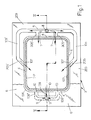
- Fig. 1 is a plan view, from above, of a possible embodiment of a drawer which supports the tray with the product during packaging;
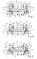
- Fig. 2 illustrates other constructional and functional details of the drawer according to Figure 1, sectioned along the line II-II and shown along with the other parts of the apparatus which comprise the foil-pressing gripper, the welding plate, the cutting blades and the means for driving and actuating the film for closing the trays;
- Figs. 3, 4 and 5 show the apparatus according to Figure 2 during subsequent working steps;
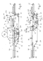
- Figs. 6 and 7 are schematic side views of a possible automatic machine which incorporates the apparatus according to the preceding figures.
- With reference to Figures 1 and 2 it can be seen that the tray V with inside it the product P to be packaged in a modified atmosphere, which usually does not project from the upper edge of the said tray, is positioned with its edge B on an annular, horizontal and
flat rim 1 which is lined by a continuous and flat seal 2 made of any suitable elastomer material which has good properties in terms of elasticity, sufficient yield, strength at the welding temperature (see below) and non-adherence with respect to the material which forms the said tray V. Therim 1, 2 surrounds theopening 103 of ahorizontal drawer 3, which opening has a form and dimensions such that it may be passed through, with play, by the body of the tray V so that the latter rests and is suspended with its edge B on thesaid rim 1, 2 which in turn has dimensions and a form such as to cooperate in a uniformly distributed manner with the bottom flat surface of the said edge B. It is obvious that, upon variation in the plan-view form and dimensions of the tray V, thedrawer 3 with the associated parts is replaced. - The
rim 1, 2 is surrounded by a continuousannular channel 4, theouter wall 104 of which has a height greater than that of the inner wall which defines thesaid rim 1 and this outer wall opens out on theupper side 203 of thedrawer 3, such that thisside 203 is at a level suitably higher than that of the edge B of the tray resting on thesaid rim 1, 2. Theupper side 203 of thedrawer 3 has, formed in it, for example by means of a milling operation, at a due distance from thechannel 4, a straight duct 5 which is parallel to one side of thesame channel 4, for example the short side, and which continues withbranches 105, 105' parallel to the consecutive sides, for example those of greater length of thesaid channel 4, into the middle part of which the saidbranches 105, 105' lead with inclined and mutually convergingsections 205, 205'. The middle part of the channel 5 has, joined to it, in a symmetrical position, the ends of theducts 305, 305' which also communicate with the short side of thechannel 4, all of which so that, by fixing in a sealed manner onto theupper side 203 of the drawer acovering plate 6 with, in the centre, anopening 106 which leaves thechannel 4 free, the end parts of thesaid branches channel 4 with - for example rectangular -apertures 7 and 107 which have the same width as each other (see below). The top end of a vertical hole with asuitable cross-section 8 opens out in the middle part of the duct 5 and has, connected at its bottom end, the circuit for supplying the modified atmosphere at appropriate pressure values, schematically indicated by the arrow IN. As can be seen from Figure 1, the duct 5 is connected to theducts 105, 105' via connected branches and thesame ducts 105, 105' as well as theend ducts 205, 205' may be formed with a depth slightly increasing towards the associateddischarge mouths 107, in order to compensate for the losses in head, so that gas is emitted from thesemouths 107 substantially with the same flowrate and/or pressure as that which emerges from the first mouths 7. - Still with reference to Figures 1 and 2 it can be seen that a duct 9 is formed, parallel to the duct 5, along the other short side of the
channel 4, at a due distance from the latter, again by means of milling in the upper side of thedrawer 3, said channel 9 continuing towards thesaid channel 4 with symmetrically arrangedbranches overlying covering plate 6, these ducts communicate with thesame channel 4 withflat mouths 10 having a suitable cross-section and, as shown in Figure 2, the middle part of the duct 9 is connected to the end of avertical hole 11 which is formed in thedrawer 3 and which at its top end is connected freely to the atmosphere, as indicated by the arrow OUT or is connected to suction means, not shown, or to other means referred to further below. The cross-section of themouths 7 and 10 will be commented upon in the remainder of the description. - The
drawer 3 is mounted on any suitable at least horizontal movement means such that the said drawer is able to pass from a position which allows loading of the tray on therim 1, 2 into a position for flushing and closing the said tray and such that the said drawer may then be retracted for unloading the packaged tray and for replacing the latter with a new tray to be packaged. Operation of thetray 3 and the tray loading and unloading operations may be performed manually or may be automated as per the example indicated further below. While in the loading position, thedrawer 3 is free at the top, in the other operating position the same drawer is positioned underneath a length offilm 112 unwound from areel 12, driven onsuitable rollers storage spool 14, this latter component and preferably also thereel 12 being operated by motor-driven means so that the said length of film which is situated above thedrawer 3 is suitably extended. When thedrawer 3 reaches the tray packaging station, the said drawer is centred vertically in a precision manner relative to theoverlying operating head 15 which is located at a suitable distance from thefilm 112 and which is connected to vertical raising and loweringmeans 16, the thrust of which during the downward stroke may be programmed (see below). Thehead 15 has an upper table 115 which is directly connected to the vertical movement means 16 and which has, mounted on its perimeter underneath,linear pressers 17 with abottom lining 117 of suitable elastically yielding material, formed integrally withvertical rods 18 which pass in a guided manner through correspondingvertical holes 19 provided in the table 115 and are provided at the top with ananti-extraction head 118 and for example are fitted along the section underneath the said table 115 with cylindrical-helix springs 20 which have suitable properties. Thepressers 17 have their bottom side which lies in a common horizontal ideal plane and are arranged so that, when thehead 15 is lowered during the active working stroke, the said pressers touch with their bottom rubber-lined side a portion of thefilm 112 which is situated outside and all the way around theannular channel 4 of thedrawer 3, as shown in Figure 3, so as to fix the said film on thesaid drawer 3. In synchronism with operation of thepressers 17, conditioning of the atmosphere inside the tray V is activated, the latter being closed inside a chamber C which is defined partly by the said tray, by thesupport rim 1, 2, by theannular channel 4 and by the coveringfilm 112 which is retained by thepressers 17 and this chamber C is connected on one side to thepipe 8 and to the means IN which in synchronism introduce the modified atmosphere for conservation of the product and on the other side is connected to thedischarge pipe 11. Thepipe 8 may be connected permanently to the source supplying the modified atmosphere, for example by means of a flexible tube, or the connection to this station may be performed in an impromptu manner, only when thedrawer 3 is situated underneath theoperating head 15, by means of a coupling mounted on special raising and lowering means, all of which in a manner which can be readily and easily realized by persons skilled in the art. The modified atmosphere gradually occupies the said chamber C, expelling the air through theduct 11, until this chamber is completely saturated. The modified atmosphere may be supplied continuously, with a constant pressure or with a variable pressure, or may be supplied at a constant pressure, but intermittently, depending on the requirements which may be conditioned by the shape and/or the quantity of product placed inside the tray V. Usually, the modified atmosphere which will be trapped inside the tray V must not be under pressure, so that, also so as to favour initial evacuation of the air from the said tray, the sum of the cross-sections of thedischarge mouths 10 is equal to or greater than the sum of the cross-sections of the supply mouths 7, 107 (Fig. 1). If, on the other hand, packaging must be performed at the correct pressure, thedischarge duct 11 may, for example, be connected to a variable throttling device which is driven by means which will allow it to intervene during the final stage of the cycle for internal conditioning of the tray, so as to slow down discharging and achieve the desired pressure condition inside the said tray. - The same upper table 115 of the
head unit 15 has, suspended from it, awelding plate 21 which is provided at the bottom with ahorizontal edge 121 projecting downwards and lined with a suitable material which is non-adhesive with respect to the film and heated by suitableelectric resistances 22 which are housed in thesaid plate 21 and connected to the power supply bush 122 and operation of which is controlled by at least one temperature probe 23. Thebottom edge 121 of theheating plate 21 is such as to reproduce the plan-view form of the upper edge B of the tray V and is initially raised from the ideal plane in which the bottom edge of thepressers 17 lies so that, during the aforementioned step for conditioning the internal atmosphere of the tray, thesaid edge 121 is suitably raised from thefilm 112. Thewelding plate 21 is suspended from the table 115 by means ofvertical rods 24 which slide insidevertical guide seats 25 which are thermally insulated and situated in the same table 115 and on which the saidrods 24 normally rest with theirheads 124 both by means of gravity and as a result of the action of cylindrical-helix springs 26 which, for example, are fitted on the section of therods 24 projecting underneath theguide seats 25. A shearing orcutting frame 27 is provided around thewelding plate 21 and is fixed at the top at 127 to the perimetral edge of a recess of the table 115 and has abottom edge 227 with a cutting action, for example having sawteeth and converging towards theplate 21. When thewelding plate 21 is in the rest position, theedge 227 of thecutting frame 27 is suitably raised relative to thebottom edge 121 of thesaid plate 21, all of which so that when, during the lowering movement of theoperating head 15, after operation of the foil-pressingpressers 17 and once conditioning of the internal atmosphere of the tray V has been performed, thebottom edge 121 of the welding plate touches thefilm 112 which is retained externally by thesaid pressers 17, stretches it suitably and pushes it onto the edge B of the tray, so as to heat-weld it onto this edge (see Figure 4), trapping the modified atmosphere for conserving the product inside the said tray. In sequence, while thehead 15 continues its downwards movement, thesprings 26 of thewelding plate 21 are also compressed and thebottom edge 227 of thecutting frame 27 is lowered with respect to thewelding edge 121, as illustrated in Figure 5, in order to perform the cutting operation which separates the length offilm 112 which closes the tray, from the outer waste material of the said film. At the end of this step, an end-of-travel device 28, which is integral, for example, with theplate 115, comes into contact with thewelding plate 21 so as to ensure that theactuator 16 for lowering thehead 15 is able to push thesaid plate 21 during the welding action, with a programmed pressure. Once welding has been performed, thehead 15 is raised, as can be seen from Figure 2, and thedrawer 3 with the packaged tray is moved away so as to allow the unloading of the said closed tray and its replacement with a new tray to be packaged. In synchronism themeans 112 for moving thefilm 112 are activated so that the waste material 112' of the film, produced during the previous cycle, is conveyed away towards thestorage spool 14 and a new length of intact film is positioned underneath the closing and shearinghead 15. - It is obvious that, with a variation in the plan-view format of the trays V to be packaged, it is required to replace, in addition to the
drawer 3, also theentire operating head 15. The apparatus, as described, may be easily designed so as to handle simultaneously several trays, in particular if of medium-to-small format, arranged in succession with each other and/or alongside each other. - The apparatus, as described, may be mounted effectively in a part of the machine which performs the automatic movement of the
drawer 3 and the trays V during loading and unloading into and from the drawer, as described in the patent application cited in the introduction and as illustrated schematically in Figures 6 and 7. From Figure 6 it can be seen that theroller 213 for driving the film, which is situated downstream of theoperating head 15, is mounted on anarm 29 mounted with the possibility of pivoting about afulcrum 129 supported by the table 115 of thehead 15 and that it is pushed downwards by spring means, not shown, all of which in such a way that, when thesaid head 15 is raised at the end of each working cycle, the length of film 112' in which a window was formed during the previous cycle, is arranged obliquely so as to allow unloading of the packaged tray underneath the raisedroller 213. The trays V are fed forwards by means of a belt orband conveyor 30 driven overrollers downstream roller 31 of which is connected to adrive unit 32 which is controlled by the processor for controlling the machine itself. The upper section of theconveyor 30 has an intermediate depression which has a length suitably greater than that of the trays to be treated during each cycle and in which the belts of this section of the conveyor follow a U-shaped path as a result of being driven over at least fourrollers carriage 34 which may be displaced horizontally by suitable means from the position shown in Figure 6, where it is upstream of thehead 15, for the tray loading and unloading operations (see below), into the position according to Figure 7 where it is situated underneath thehead 15 for the operation of packaging the said trays. Thefront section 130 of theconveyor 30 travels over aflat structure 35 which is fixed to the chassis of the machine and has a length such as to support at least one tray V to be packaged, while theend part 230 of the upper section of the said conveyor is free of obstacles so as not hinder the travel of thecarriage 34 on which thedrawer 3 described above is mounted, in such a way that the upper side of theplate 6 of this drawer is coplanar with the upper section of theconveyor 30 in question. Thesame carriage 34 has, mounted thereon, thevertical guides 136 and the actuator for the vertical movement of a horizontal lifting table 36 which may be raised inside theopening 103 of thedrawer 3, so as to be arranged with its upper side coplanar with that of the said drawer, as illustrated in broken lines in Figure 6, or which may be lowered as illustrated in continuous lines. The machine is completed by a fixedstop cross-bar 37 which is situated above theupstream roller 113 for driving the film, a further fixedstop cross-bar 38 situated upstream of thecross-bar 37 and afurther cross-bar 39 situated upstream of thecross-bar 38, at a distance from the latter which is slightly greater than the length of the product to be fed into thedrawer 3 and connected to raising and lowering means which are schematically indicated by thearrow 139. At the start of each working cycle, thecarriage 34 is in the retracted position shown in Figure 6, with the lifting table 36 in the high position, with a tray V1 resting against the middle cross-bar 38 (see below) and detected by asensor 40, with thecross-bar 39 lowered and with theconveyor 30 activated so that the next tray V2 is stopped against thesaid cross-bar 39 and detected by asensor 41. When these conditions arise, theconveyor 30 stops, the lifting table 36 moves downwards so as to position the tray V1 on therim 1, 2 of thedrawer 3 and, when this condition is detected by thesensor 40, the forward movement of thecarriage 34 is effected so as to bring the tray V1 underneath thehead 15 in order to perform the operating steps described with reference to Figures 1 to 5. With the descending movement of thehead 15, thefilm 112 passes from the inclined position into the horizontal position for covering the tray. During the step for packaging the tray V1, theconveyor 30 can be activated with simultaneous raising of theupstream cross-bar 39 so as to bring the tray V2 against thefixed middle cross-bar 38 and, when this condition is detected by thesensor 40, the said upstreamcross-bar 39 is lowered and theconveyor 30 is stopped immediately or when thesensor 41 detects a further tray against the said loweredcross-bar 39. - Once packaging of the tray V1 has been performed, in correct sequence with raising of the
head 15 which arranges the waste material 112' of the film in an inclined position as can be seen from Figure 6, the lifting table 36 is raised and brings the closed tray V1 above thedrawer 3 such that, when thecarriage 34 is subsequently retracted towards the left, as can be seen from Figure 6, the same tray is retained by thefixed cross-bar 37 and is arranged on the upper right-hand section 230 of theconveyor 30 which is gradually lengthened and, when the carriage reaches the start-of-cycle position, it finds the tray V2 which is arranged on its lifting table 36 in the high position, ready to be inserted inside thedrawer 3 for repetition of a new working cycle. While thecarriage 34 moves to the left or when it then moves to the right, theconveyor 30 is reactivated so as to move the closed tray V1 away from thehead 15 and transfer it onto a motor-drivendownstream conveyor 42, while the transfer of the packaging is detected by asensor 43 which signals to the processor of the machine the correct execution of the working steps. In sequence with the steps described, the means for unwinding thefilm 112 from thereel 12 and the means for storing the waste material 112' on thespool 14 are activated so as to position a new intact and extended length of the saidfilm 112 underneath thehead 15.
Claims (23)
- Apparatus for packaging products in a modified atmosphere, consisting of trays (V) which are made of plastic with a barrier effect and contain a product (P) and on the upper edge (B) of which a thermoplastic film with a barrier effect must be sealingly heat-welded, after the ambient air inside the said tray has been replaced with a modified atmosphere useful for conservation of the product (P), characterized in that it comprises a horizontal drawer (3) with an opening (103) through which the body of the tray to be packaged can pass, said tray with its edge (B) resting on the upper, horizontal and flat side of an annular rim (1) which surrounds the said opening and, around this rim, the drawer has a continuous annular channel (4), the outer shoulder (104) of which has a height greater than that of the inner shoulder and opens out on the upper side (203) of the said drawer which is thus at a height greater than that of the said rim (1) and the upper edge (B) of the tray positioned on the latter, there being envisaged means for arranging, extended, on the upper side of the said drawer with the tray inside it a length of barrier film (112) and foil-pressing means (17) being envisaged for, when operated, pressing the film onto the upper side of the drawer (3), at a due distance from the outer shoulder of the said annular channel (4), all of which so as to form a packaging chamber (C) which is substantially closed with respect to the exterior and is defined at the bottom by the tray (V), at the top by the said barrier film and along the sides by the said annular channel (4) which has along at least one side one or more openings (7) through which, upon operation, the modified atmosphere may be blown into the said chamber (C), while on the opposite side of the said annular channel (4) one or more discharge openings (10) are provided, through which openings firstly the air contained inside the tray, pushed by the front edge of the incoming modified atmosphere, is able to pass out and also part of the said modified atmosphere can pass out, there being envisaged a heat-welding plate (21) which in sequence is lowered and pushed onto the edge (B) of the tray so as to heat-weld onto the latter the said closing film (112) and trap in the packaging thus formed the quantity of modified atmosphere useful for conserving the product, there also being envisaged cutting means (27) which, following the aforementioned heat-welding, separate from the film the closed tray containing inside it the product packaged in a modified atmosphere.
- Apparatus according to Claim 1, in which the upper side of the rim (1), on which the edge (B) of the tray to be packaged rests, is lined with a suitable material (2) which is sufficiently elastic and non-adhesive, so as to satisfy the operating requirements of a welding die and such as to ensure a good sealed joint with the bottom surface of the said edge (B) of the tray.
- Apparatus according to Claim 1, in which the said openings (7) for introducing the modified atmosphere into the said packaging chamber (C) and the said discharge openings (10) are provided with ducts (5, 105, 105', 205, 205' and 9, 109, 109', 109") formed by means of milling or some other technique on the upper side (203) of the drawer (3) and then covered with at least one flat plate (6) which is fixed sealingly with respect to the exterior onto the said drawer, the said ducts being connected to the end of respective delivery and discharge holes or pipes (8, 11).
- Apparatus according to Claim 3, in which the said supply and discharge openings (7, 10) of the packaging chamber (C) are situated in a symmetrical manner with respect to the middle axes of the said chamber (C).
- Apparatus according to Claim 4, in which the openings (7) for supplying the modified atmosphere into the packaging chamber (C) are such as to discharge in a distributed manner on one side of this chamber and also in the middle part of the two consecutive sides, with compensation of the head losses, while the discharge openings (10) are situated on the remaining side of the said chamber (C).
- Apparatus according to Claim 4, in which the sum of the cross-sections of the discharge openings (10) is equal to or greater than the sum of the cross-sections of the openings (7) supplying the modified atmosphere, so as to allow rapid evacuation of the ambient air from the packaging chamber (C), pushed by the front edge of the modified atmosphere introduced into this chamber through the said supply openings (7).
- Apparatus according to one or more of the preceding claims, in which means are envisaged for introducing the modified atmosphere into the packaging chamber (C) with constant, continuous or intermittent pressure characteristics, or at a variable pressure, depending on the packaging requirements.
- Apparatus according to Claim 6, in which a variable throttle device may be mounted on the discharge duct (11) connected to the corresponding openings (10) and means are envisaged for ensuring that this throttle device is activated at the end of the cycle in order to reduce the discharge and ensure the accumulation, inside the packaging chamber (C), of modified atmosphere at correct pressure values which remain inside the packaged tray, the closing film of which will appear slightly swollen and curved towards the outside.
- Apparatus according to Claim 1, in which the said foil-pressing means (17), the welding plate (21) and the said cutting or shearing means (27) are mounted on a same head (15) which operates in a static position and is operated by suitable raising and lowering means (16) with control of the force during the active lowering phase, and manually or automatically operated means are envisaged for displacing horizontally the drawer (3) so as to bring it from a position where it is accessible for the tray loading and unloading operations into a position situated underneath the said operating head (15) and underneath a length of film (112) unwound from a reel (12) and stored on a spool (14) using associated drive means, for implementing the steps for packaging the tray under a modified atmosphere.
- Apparatus according to Claim 9, in which the said operating head (15) has an upper table (115) which is connected to the said vertical movement means (16) and has, mounted on its perimeter underneath, linear pressers (17), with a bottom lining (117) made of suitable elastic and yielding material, supported by vertical rods (18) which pass through in a guided manner corresponding vertical holes (19) formed in the said table (115) and are provided at the top with an anti-extraction head (118) and for example are fitted along the section underneath the said table (115) with cylindrical-helix springs (20) with suitable properties, it being envisaged that the bottom side of the said pressers (17) lies in an ideal plane which is substantially horizontal so that, when the head (15) is lowered during the active working stroke, the said pressers touch with their rubber-lined bottom side a portion of the underlying film (112) which is situated outside and all the way around the annular channel (4) of the drawer (3), so as to fix the said film on the said drawer (3) so that it is then possible to perform the step of introducing the modified atmosphere into the said packaging chamber (C).
- Apparatus according to Claim 10, in which the said upper table (115) of the head (15) has, suspended from it, a welding plate (21) which is provided at the bottom with a horizontal edge (121) projecting downwards and lined with suitable material which is non-adhesive with respect to the film and heated by suitable electric resistances (22) which are seated in the said welding plate (21) and operation of which is controlled by at least one temperature probe (23) and by the processor of the machine, the said bottom edge (121) being such as to reproduce the plan-view form of the upper edge (B) of the tray (V) and being initially raised from the ideal plane in which the base of the said foil-pressing pressers (17) lies in such a way that, during internal atmospheric conditioning of the tray, the said welding edge (121) is suitably raised from the film (112), the welding plate (21) also being suspended from the said table (115) by means of vertical rods (24) which slide inside vertical thermally insulated guide seats (25) which are situated on the said table (115) and on which the said rods (24) normally rest with their heads (124) both by means of gravity and as a result of the action of cylindrical-helix springs (26) which for example are fitted on the section of the rods (24) projecting underneath the said guide seats (25).
- Apparatus according to Claim 10, in which a cutting frame (27) is provided around the welding plate (21) and is fixed at the top inside a recess of the said table (115) and has a bottom edge (227) with a cutting action, i.e. preferably having sawteeth and converging towards the said plate (21), it being envisaged that, when this plate (21) is in the rest position, the bottom edge (227) of the cutting frame (27) is suitably raised relative to the bottom edge (121) of the said welding plate (21), all of which so that when, during the lowering movement of the operating head (15), after operation of the foil-pressing pressers (17) and once conditioning of the internal atmosphere of the tray (V) has been performed, the bottom edge (121) of the welding plate touches the film (112) which is retained externally by the said pressers (17), stretches it suitably and pushes it onto the edge (B) of the tray, so as to heat-weld it onto this tray, trapping the modified atmosphere for conserving the product inside the said tray, it being envisaged that, while the head (15) continues its downwards movement, the springs (26) of the welding plate (21) are also compressed and the bottom edge (227) of the cutting frame (27) is lowered with respect to the welding edge (121), in order to perform the cutting operation which separates the length of film (112) which closes the tray, from the external waste material (112') of the said film.
- Apparatus according to Claim 12, characterized in that, after the step for cutting and separating from the continuous film the length of the said film welded onto the top edge of the tray (V), at least one end-of-travel device (28) integral for example with the movable table (115) of the operating head (15) comes into contact with the welding plate (21) so that the actuator (16) for lowering the said head (15) is able to push the welding plate (21) during the welding action, with a programmed and controlled thrusting force.
- Apparatus according to Claim 9, in which, upon welding and cutting performed on the closing film of the tray (V), the said drive means (16) raise the operating head (15) and means are envisaged for moving the drawer (3) with the closed tray horizontally away from this head so that said drawer may be unloaded and loaded with a new tray to be packaged, it being envisaged that the means for moving the film (112) are activated in synchronism so that the waste material of the film (112') produced during the previous cycle is conveyed away to the storage spool (14) and a new length of intact film (112) is arranged underneath the closing and shearing head (15).
- Apparatus according to any one or more of the preceding claims, characterized in that it is designed to handle one tray at a time or to handle several trays simultaneously, in particular if of small-to-medium size, arranged in succession with each other and/or alongside each other.
- Apparatus according to any one or more of the preceding claims, characterized in that, during association with a machine for automatically moving the drawer (3) and for automatically performing the operations of loading and unloading the trays into and from the said drawer, the roller (213) on which the length of film (112) to be welded onto the upper edge of the tray is driven and which is situated on the side for unloading the said tray when packaged, is mounted on an arm (29) with the possibility of pivoting on a fulcrum (129) which is supported by the table (115) of the operating head (15) and which is pushed downwards by spring means, all of which so that when the said head (15) is raised at the end of each working cycle, the length of film (112'), devoid of the cover portion fixed onto the packaged tray and therefore with a window inside it, is arranged obliquely so as to favour unloading of the closed tray underneath the said raised drive roller (213).
- Apparatus according to Claim 16, in which the trays (V) to be packaged are fed forwards the upper and horizontal section of a belt or band conveyor (30) driven over rollers (31, 131, 231, 331, 431) which are supported rotatably by the fixed chassis of the machine and the downstream roller (31) of which is connected to a drive unit (32) which is controlled by the processor for controlling the machine itself, the upper section of the said conveyor (30) having an intermediate depression which has a length suitably greater than that of the trays to be treated during each cycle and in which the belts of this section of the conveyor follow a U-shaped path as a result of being driven over at least four rollers (33, 133, 233, 333) which are rotatably supported by a carriage (34) which may be displaced horizontally by suitable means from the position where it is upstream of the said pressing, welding and cutting head (15), so as to be able to perform at least the operations for loading the tray to be packaged, into the position where it is situated underneath the said operating head (15) for the operations of packaging the said trays, for this purpose it being envisaged that the front section (130) of the upper section of the conveyor (30) travels over a flat structure (35) which is fixed to the chassis of the machine and has a length such as to support at least one tray (V) to be packaged, while the end part (230) of the upper section of the said conveyor is free of obstacles so as not to hinder the travel of the said carriage (34) on which the said drawer (3) is mounted, so that its upper side is coplanar with the upper section of the conveyor (30) in question.
- Apparatus according to Claim 17, in which said carriage (34) has, mounted thereon, the vertical guides (136) and the actuator for the vertical movement of a horizontal lifting table (36) which may be raised during opening (103) of the drawer (3), so as to be arranged with its upper side coplanar with that of the said drawer, or which may be lowered.
- Apparatus according to Claim 18, in which a fixed stop cross-bar (37) is envisaged above the upstream roller (113) for driving the film, a further fixed stop cross-bar (38) is envisaged upstream of the aforementioned cross-bar (37) and a further cross-bar (39) is envisaged upstream of the previous cross-bar (38), at a distance from the latter slightly greater than the length of the tray to be fed cyclically into the drawer (3) and this last cross-bar (39) being connected to raising and lowering means (139).
- Apparatus according to Claim 19, characterized in that it comprises means so that, at the start of each working cycle, the said carriage (34) is in the position retracted from the operating head (15), with the lifting table (36) in the high position, while a tray (V1) rests against the middle cross-bar (38) and is detected by a sensor (40) and with the upstream cross-bar (39) lowered and with the conveyor (30) active, so that the next tray (V2) is stopped against this cross-bar (39) and is detected here by a sensor (41) and, when these conditions arise, means are envisaged for ensuring that the conveyor (30) stops, that the lifting table (36) moves downwards so as to position the tray (V1) on the rim (1, 2) of the drawer (3) and, when this condition is detected by the overlying sensor (40), means effect the forward movement of the carriage (34) which brings the tray (V1) underneath the operating head (15) for packaging of this tray under a modified atmosphere, it being envisaged that, during the descending movement of the head (15), the film (112) passes from the inclined position into the horizontal position for covering the tray.
- Apparatus according to Claim 20, characterized in that it comprises means for ensuring that, during the step for packaging the tray (V1), the conveyor (30) can be activated with simultaneous raising of the upstream cross-bar (39), so as to bring a tray (V2) against the next fixed middle cross-bar (38) and, when this condition is detected by the sensor (40), the said upstream cross-bar (39) is lowered and the conveyor (30) is stopped immediately or when the sensor (41) detects a further tray against the said lowered cross-bar (39).
- Apparatus according to Claim 21, characterized in that it comprises means for ensuring that, once packaging of the tray (V1) has been performed, in correct sequence with raising of the operating head (15) which arranges the waste material (112') of the film in an inclined position, the lifting table (36) is raised and brings the said packaged tray (V1) above the drawer (3) such that, when the carriage (34) is subsequently retracted, the same tray is retained by the fixed downstream cross-bar (37) and is arranged on the part (230) of the upper section (230) of the conveyor (30) which is gradually lengthened and, when the carriage reaches the start-of-cycle position, it finds a tray (V2) which is arranged on the lifting table (36) in the high position, ready to be inserted inside the drawer (3) for repetition of a new working cycle.
- Apparatus according to Claim 22, characterized in that means are envisaged for ensuring that, while the carriage (34) is retracted or when it then advances towards the operating head (15), the said conveyor (30) is reactivated so as to move the packaged tray (V1) away from the operating head (15) and transfer it onto a motor-driven downstream conveyor (42), while the transfer of the packaging is detected by a sensor (43) which signals to the processor of the machine the correct execution of the working steps, means being envisaged so that, in sequence with the steps described, the means for unwinding the film from the reel (12) and the means for storing the waste material (112') on the spool (14) are activated so as to position a new intact length of the said film (112) underneath the operating head (15).
Applications Claiming Priority (1)
| Application Number | Priority Date | Filing Date | Title |
|---|---|---|---|
| IT000249A ITBO20060249A1 (en) | 2006-04-05 | 2006-04-05 | APPARATUS AND MACHINE TO PACK PRODUCT TRAYS IN MODIFIED ATMOSPHERE. |
Publications (3)
| Publication Number | Publication Date |
|---|---|
| EP1842776A2 true EP1842776A2 (en) | 2007-10-10 |
| EP1842776A3 EP1842776A3 (en) | 2007-10-31 |
| EP1842776B1 EP1842776B1 (en) | 2009-08-19 |
Family
ID=38123969
Family Applications (1)
| Application Number | Title | Priority Date | Filing Date |
|---|---|---|---|
| EP07104527A Active EP1842776B1 (en) | 2006-04-05 | 2007-03-20 | Apparatus for packaging trays containing products in a modified atmosphere |
Country Status (5)
| Country | Link |
|---|---|
| EP (1) | EP1842776B1 (en) |
| AT (1) | ATE440031T1 (en) |
| DE (1) | DE602007001993D1 (en) |
| ES (1) | ES2331210T3 (en) |
| IT (1) | ITBO20060249A1 (en) |
Cited By (20)
| Publication number | Priority date | Publication date | Assignee | Title |
|---|---|---|---|---|
| WO2009144714A2 (en) * | 2008-05-27 | 2009-12-03 | Hefestus Ltd | Food container sealing |
| ITMI20092003A1 (en) * | 2009-11-13 | 2011-05-14 | I L P R A S P A | SEALING UNIT IN CONTROLLED ATMOSPHERE OF TRAYS AND / OR SIMILAR CONTAINERS FOR PACKAGING FOOD PRODUCTS |
| ITBO20100045A1 (en) * | 2010-01-26 | 2011-07-27 | Gruppo Fabbri S P A | SYSTEM FOR PACKAGING IN MODIFIED ATMOSPHERE OF PRODUCTS PLACED IN TRAYS. |
| ITMI20100471A1 (en) * | 2010-03-23 | 2011-09-24 | Tecnovac S R L | MACHINE TO CARRY OUT THE PACKAGING, BY SEALING WITH SYNTHETIC FILM, OF PRODUCTS, IN PARTICULAR FOOD PRODUCTS, IN CONTAINERS OF THE TYPE OF TRAYS, TRAYS OR SIMILAR, WITH HIGH FLEXIBILITY OF USE. |
| ITBO20100211A1 (en) * | 2010-04-08 | 2011-10-09 | Gruppo Fabbri S P A | APPARATUS BELLS APPARATUS, FOR PACKAGING IN MODIFIED ATMOSPHERE OF PRODUCTS PLACED IN TRAYS. |
| EP2468633A1 (en) * | 2010-12-27 | 2012-06-27 | Multivac Sepp Haggenmüller GmbH & Co. KG | Tray closing machine and method for operating the same |
| DE102012005891A1 (en) * | 2012-03-23 | 2013-09-26 | Multivac Sepp Haggenmüller Gmbh & Co. Kg | Packaging machine with sealing station for gassing a packaging |
| EP2676888A1 (en) * | 2012-06-22 | 2013-12-25 | Multivac Sepp Haggenmüller GmbH & Co. KG | Sealing device of a tray sealing machine |
| WO2014080053A1 (en) * | 2012-11-21 | 2014-05-30 | Manuel Ruiz Carmona | Appliance for joining a sheet-type body to the mouth of a box |
| CN104003018A (en) * | 2013-09-12 | 2014-08-27 | 温州市沪华机械电器有限公司 | Vacuum pumping opening sealing device |
| EP3095717A1 (en) | 2015-05-21 | 2016-11-23 | MULTIVAC Sepp Haggenmüller SE & Co. KG | Jacket closing machine |
| WO2016193006A1 (en) * | 2015-05-29 | 2016-12-08 | Cryovac, Inc. | Apparatus and process for packaging a product |
| WO2020002934A1 (en) * | 2018-06-29 | 2020-01-02 | Randox Laboratories Ltd | Cartridge sealing apparatus |
| WO2020044031A1 (en) * | 2018-08-29 | 2020-03-05 | Proseal Uk Limited | Packaging apparatus with a flushing gas inlet and outlet |
| US10741432B2 (en) * | 2017-02-06 | 2020-08-11 | Applied Materials, Inc. | Systems, apparatus, and methods for a load port door opener |
| EP3733528A1 (en) * | 2019-05-02 | 2020-11-04 | MULTIVAC Sepp Haggenmüller SE & Co. KG | Sealing tool and method for sealing trays |
| JP2021031179A (en) * | 2019-08-27 | 2021-03-01 | 朱暁鳳 | Reliable food vacuum packaging machine |
| US20220063849A1 (en) * | 2020-08-27 | 2022-03-03 | Sonoco Development, Inc. | Systems and methods for the application and sealing of end closures on containers |
| CN114408286A (en) * | 2022-01-07 | 2022-04-29 | 江苏旭鹏智能科技有限公司 | Continuous box type modified atmosphere packaging machine simple to operate |
| WO2022099197A1 (en) * | 2020-11-09 | 2022-05-12 | Sonoco Development, Inc. | Seal and cut assembly for heat sealing machine |
Citations (5)
| Publication number | Priority date | Publication date | Assignee | Title |
|---|---|---|---|---|
| WO1997045324A1 (en) * | 1996-05-31 | 1997-12-04 | Ross Industries, Inc. | Food product wrapping |
| WO2000038992A1 (en) * | 1998-12-23 | 2000-07-06 | Cryovac, Inc. | Process for packaging high profile products in a modified atmosphere with an upwardly formed heat shrinkable film |
| WO2000050305A1 (en) * | 1999-02-24 | 2000-08-31 | Hefestus Ltd. | Packaging method and apparatus |
| US6202388B1 (en) * | 1998-11-06 | 2001-03-20 | Jescorp, Inc. | Controlled environment sealing apparatus and method |
| US20030196412A1 (en) * | 2002-04-19 | 2003-10-23 | Foulke Guy L. | Top formed packaging |
-
2006
- 2006-04-05 IT IT000249A patent/ITBO20060249A1/en unknown
-
2007
- 2007-03-20 DE DE602007001993T patent/DE602007001993D1/en active Active
- 2007-03-20 EP EP07104527A patent/EP1842776B1/en active Active
- 2007-03-20 AT AT07104527T patent/ATE440031T1/en not_active IP Right Cessation
- 2007-03-20 ES ES07104527T patent/ES2331210T3/en active Active
Patent Citations (5)
| Publication number | Priority date | Publication date | Assignee | Title |
|---|---|---|---|---|
| WO1997045324A1 (en) * | 1996-05-31 | 1997-12-04 | Ross Industries, Inc. | Food product wrapping |
| US6202388B1 (en) * | 1998-11-06 | 2001-03-20 | Jescorp, Inc. | Controlled environment sealing apparatus and method |
| WO2000038992A1 (en) * | 1998-12-23 | 2000-07-06 | Cryovac, Inc. | Process for packaging high profile products in a modified atmosphere with an upwardly formed heat shrinkable film |
| WO2000050305A1 (en) * | 1999-02-24 | 2000-08-31 | Hefestus Ltd. | Packaging method and apparatus |
| US20030196412A1 (en) * | 2002-04-19 | 2003-10-23 | Foulke Guy L. | Top formed packaging |
Cited By (37)
| Publication number | Priority date | Publication date | Assignee | Title |
|---|---|---|---|---|
| WO2009144714A3 (en) * | 2008-05-27 | 2010-01-28 | Hefestus Ltd | Food container sealing |
| WO2009144714A2 (en) * | 2008-05-27 | 2009-12-03 | Hefestus Ltd | Food container sealing |
| ITMI20092003A1 (en) * | 2009-11-13 | 2011-05-14 | I L P R A S P A | SEALING UNIT IN CONTROLLED ATMOSPHERE OF TRAYS AND / OR SIMILAR CONTAINERS FOR PACKAGING FOOD PRODUCTS |
| US9150316B2 (en) | 2010-01-26 | 2015-10-06 | Gruppo Fabbri Vignola S.P.A. | Apparatus for modified atmosphere packaging of products placed in trays |
| ITBO20100045A1 (en) * | 2010-01-26 | 2011-07-27 | Gruppo Fabbri S P A | SYSTEM FOR PACKAGING IN MODIFIED ATMOSPHERE OF PRODUCTS PLACED IN TRAYS. |
| WO2011092103A1 (en) * | 2010-01-26 | 2011-08-04 | Gruppo Fabbri S.P.A. | Apparatus for modified atmosphere packaging of products placed in trays |
| ITMI20100471A1 (en) * | 2010-03-23 | 2011-09-24 | Tecnovac S R L | MACHINE TO CARRY OUT THE PACKAGING, BY SEALING WITH SYNTHETIC FILM, OF PRODUCTS, IN PARTICULAR FOOD PRODUCTS, IN CONTAINERS OF THE TYPE OF TRAYS, TRAYS OR SIMILAR, WITH HIGH FLEXIBILITY OF USE. |
| EP2380810A3 (en) * | 2010-03-23 | 2012-02-22 | Tecnovac S.r.L. | Machine for packaging, by sealing with synthetic film, products, particularly food products, in containers such as trays, tubs or the like, with high flexibility in use |
| AU2011237995B2 (en) * | 2010-04-08 | 2015-05-07 | Gruppo Fabbri Vignola S.P.A. | Apparatus with opposing housings for modified atmosphere packaging of products placed in trays |
| US9555910B2 (en) | 2010-04-08 | 2017-01-31 | Gruppo Fabbri Vignola S.P.A. | Apparatus with opposing housings for modified atmosphere packaging of products placed in trays |
| EP2555981B1 (en) | 2010-04-08 | 2018-06-27 | Gruppo Fabbri Vignola S.p.A. | Method for modified atmosphere packaging of products placed in trays |
| WO2011124548A1 (en) * | 2010-04-08 | 2011-10-13 | Gruppo Fabbri Vignola S.P.A. | Apparatus with opposing housings for modified atmosphere packaging of products placed in trays |
| ITBO20100211A1 (en) * | 2010-04-08 | 2011-10-09 | Gruppo Fabbri S P A | APPARATUS BELLS APPARATUS, FOR PACKAGING IN MODIFIED ATMOSPHERE OF PRODUCTS PLACED IN TRAYS. |
| EP2468633A1 (en) * | 2010-12-27 | 2012-06-27 | Multivac Sepp Haggenmüller GmbH & Co. KG | Tray closing machine and method for operating the same |
| US9481480B2 (en) | 2012-03-23 | 2016-11-01 | Multivac Sepp Haggenmueller Se & Co. Kg | Packaging machine with sealing station for gas flushing a package |
| DE102012005891A1 (en) * | 2012-03-23 | 2013-09-26 | Multivac Sepp Haggenmüller Gmbh & Co. Kg | Packaging machine with sealing station for gassing a packaging |
| EP2676888A1 (en) * | 2012-06-22 | 2013-12-25 | Multivac Sepp Haggenmüller GmbH & Co. KG | Sealing device of a tray sealing machine |
| WO2014080053A1 (en) * | 2012-11-21 | 2014-05-30 | Manuel Ruiz Carmona | Appliance for joining a sheet-type body to the mouth of a box |
| CN104003018A (en) * | 2013-09-12 | 2014-08-27 | 温州市沪华机械电器有限公司 | Vacuum pumping opening sealing device |
| EP3095717A1 (en) | 2015-05-21 | 2016-11-23 | MULTIVAC Sepp Haggenmüller SE & Co. KG | Jacket closing machine |
| WO2016193006A1 (en) * | 2015-05-29 | 2016-12-08 | Cryovac, Inc. | Apparatus and process for packaging a product |
| AU2016270276B2 (en) * | 2015-05-29 | 2019-10-10 | Cryovac, LLC. | Apparatus and process for packaging a product |
| CN107660192A (en) * | 2015-05-29 | 2018-02-02 | 克里奥瓦克公司 | Apparatus and process for packaging products |
| US10741432B2 (en) * | 2017-02-06 | 2020-08-11 | Applied Materials, Inc. | Systems, apparatus, and methods for a load port door opener |
| WO2020002934A1 (en) * | 2018-06-29 | 2020-01-02 | Randox Laboratories Ltd | Cartridge sealing apparatus |
| CN112638779A (en) * | 2018-08-29 | 2021-04-09 | 普洛希尔英国有限公司 | Packaging device with flushing gas inlet and outlet |
| WO2020044031A1 (en) * | 2018-08-29 | 2020-03-05 | Proseal Uk Limited | Packaging apparatus with a flushing gas inlet and outlet |
| US11530062B2 (en) | 2018-08-29 | 2022-12-20 | Proseal Uk Limited | Gas flush injector |
| CN112638779B (en) * | 2018-08-29 | 2023-02-03 | 普洛希尔英国有限公司 | Packaging device with flushing gas inlet and outlet |
| EP3733528A1 (en) * | 2019-05-02 | 2020-11-04 | MULTIVAC Sepp Haggenmüller SE & Co. KG | Sealing tool and method for sealing trays |
| DE102019206280A1 (en) * | 2019-05-02 | 2020-11-05 | Multivac Sepp Haggenmüller Se & Co. Kg | Sealing tool and method for sealing trays |
| EP3733528B1 (en) * | 2019-05-02 | 2022-02-09 | MULTIVAC Sepp Haggenmüller SE & Co. KG | Sealing tool and method for sealing trays |
| US11492160B2 (en) | 2019-05-02 | 2022-11-08 | Multivac Sepp Haggenmueller Se & Co. Kg | Sealing tool and method for sealing trays |
| JP2021031179A (en) * | 2019-08-27 | 2021-03-01 | 朱暁鳳 | Reliable food vacuum packaging machine |
| US20220063849A1 (en) * | 2020-08-27 | 2022-03-03 | Sonoco Development, Inc. | Systems and methods for the application and sealing of end closures on containers |
| WO2022099197A1 (en) * | 2020-11-09 | 2022-05-12 | Sonoco Development, Inc. | Seal and cut assembly for heat sealing machine |
| CN114408286A (en) * | 2022-01-07 | 2022-04-29 | 江苏旭鹏智能科技有限公司 | Continuous box type modified atmosphere packaging machine simple to operate |
Also Published As
| Publication number | Publication date |
|---|---|
| ATE440031T1 (en) | 2009-09-15 |
| EP1842776B1 (en) | 2009-08-19 |
| EP1842776A3 (en) | 2007-10-31 |
| ITBO20060249A1 (en) | 2007-10-06 |
| DE602007001993D1 (en) | 2009-10-01 |
| ES2331210T3 (en) | 2009-12-23 |
Similar Documents
| Publication | Publication Date | Title |
|---|---|---|
| EP1842776B1 (en) | Apparatus for packaging trays containing products in a modified atmosphere | |
| KR950011387B1 (en) | Form-fill-seal deflation method and apparatus | |
| US8033085B2 (en) | Machine for shaping, filling and closing expanded polymer containers | |
| US7506491B2 (en) | Method and machine for packaging food products in trays sealingly closed at the top with a thermoplastic film | |
| US20100287893A1 (en) | Packaging machine and method for closing containers with lids | |
| US7296390B2 (en) | Vacuum packaging machine having a plurality of vacuum chambers for performing a vacuum sealing operation on product packages | |
| US7464521B2 (en) | Vacuum packaging machine for product packages with multiple products | |
| JP2009173342A (en) | Web packaging system with ergonomic forming plug change | |
| JP2018002308A (en) | Automatic packaging machine for filling bag made of heat-sealable material with certain amount of loose product | |
| KR101827788B1 (en) | Vacuum packaging system of packaging bag for infusion solutions | |
| EP2722280A1 (en) | Packaging process and packaging apparatus | |
| CA1165221A (en) | Apparatus and method for film packaging | |
| US4622800A (en) | Sterilizing method and apparatus | |
| KR20150014694A (en) | Automatic continuous vacuum package machine | |
| KR101911666B1 (en) | pet bottle packaging apparatus | |
| CN205293195U (en) | Thermoforming vacuum packaging machine | |
| JP5605085B2 (en) | Heat seal packaging equipment | |
| JP2011073715A (en) | Inert gas flush filling and packaging machine | |
| CN112368214B (en) | Apparatus and method for supplying articles | |
| JP2926690B2 (en) | Product filling and packaging method and device | |
| US20220348369A1 (en) | Sealing machine for the sealing of packages | |
| AU686758B2 (en) | Process and device for producing a flowable product package via a shell | |
| KR200386432Y1 (en) | Small goods automatic packer | |
| EP0468776A1 (en) | Improvements in or relating to article wrapping apparatus | |
| KR101473619B1 (en) | Packing machine with open and close mechanism of transportation path |
Legal Events
| Date | Code | Title | Description |
|---|---|---|---|
| PUAI | Public reference made under article 153(3) epc to a published international application that has entered the european phase |
Free format text: ORIGINAL CODE: 0009012 |
|
| PUAL | Search report despatched |
Free format text: ORIGINAL CODE: 0009013 |
|
| AK | Designated contracting states |
Kind code of ref document: A2 Designated state(s): AT BE BG CH CY CZ DE DK EE ES FI FR GB GR HU IE IS IT LI LT LU LV MC MT NL PL PT RO SE SI SK TR |
|
| AX | Request for extension of the european patent |
Extension state: AL BA HR MK YU |
|
| AK | Designated contracting states |
Kind code of ref document: A3 Designated state(s): AT BE BG CH CY CZ DE DK EE ES FI FR GB GR HU IE IS IT LI LT LU LV MC MT NL PL PT RO SE SI SK TR |
|
| AX | Request for extension of the european patent |
Extension state: AL BA HR MK YU |
|
| 17P | Request for examination filed |
Effective date: 20080325 |
|
| 17Q | First examination report despatched |
Effective date: 20080425 |
|
| AKX | Designation fees paid |
Designated state(s): AT BE BG CH CY CZ DE DK EE ES FI FR GB GR HU IE IS IT LI LT LU LV MC MT NL PL PT RO SE SI SK TR |
|
| GRAP | Despatch of communication of intention to grant a patent |
Free format text: ORIGINAL CODE: EPIDOSNIGR1 |
|
| RAP1 | Party data changed (applicant data changed or rights of an application transferred) |
Owner name: GRUPPO FABBRI S.P.A. |
|
| GRAS | Grant fee paid |
Free format text: ORIGINAL CODE: EPIDOSNIGR3 |
|
| GRAA | (expected) grant |
Free format text: ORIGINAL CODE: 0009210 |
|
| AK | Designated contracting states |
Kind code of ref document: B1 Designated state(s): AT BE BG CH CY CZ DE DK EE ES FI FR GB GR HU IE IS IT LI LT LU LV MC MT NL PL PT RO SE SI SK TR |
|
| REG | Reference to a national code |
Ref country code: GB Ref legal event code: FG4D |
|
| REG | Reference to a national code |
Ref country code: CH Ref legal event code: EP |
|
| REG | Reference to a national code |
Ref country code: IE Ref legal event code: FG4D |
|
| REF | Corresponds to: |
Ref document number: 602007001993 Country of ref document: DE Date of ref document: 20091001 Kind code of ref document: P |
|
| REG | Reference to a national code |
Ref country code: ES Ref legal event code: FG2A Ref document number: 2331210 Country of ref document: ES Kind code of ref document: T3 |
|
| LTIE | Lt: invalidation of european patent or patent extension |
Effective date: 20090819 |
|
| PG25 | Lapsed in a contracting state [announced via postgrant information from national office to epo] |
Ref country code: SE Free format text: LAPSE BECAUSE OF FAILURE TO SUBMIT A TRANSLATION OF THE DESCRIPTION OR TO PAY THE FEE WITHIN THE PRESCRIBED TIME-LIMIT Effective date: 20090819 Ref country code: LT Free format text: LAPSE BECAUSE OF FAILURE TO SUBMIT A TRANSLATION OF THE DESCRIPTION OR TO PAY THE FEE WITHIN THE PRESCRIBED TIME-LIMIT Effective date: 20090819 Ref country code: AT Free format text: LAPSE BECAUSE OF FAILURE TO SUBMIT A TRANSLATION OF THE DESCRIPTION OR TO PAY THE FEE WITHIN THE PRESCRIBED TIME-LIMIT Effective date: 20090819 Ref country code: FI Free format text: LAPSE BECAUSE OF FAILURE TO SUBMIT A TRANSLATION OF THE DESCRIPTION OR TO PAY THE FEE WITHIN THE PRESCRIBED TIME-LIMIT Effective date: 20090819 Ref country code: IS Free format text: LAPSE BECAUSE OF FAILURE TO SUBMIT A TRANSLATION OF THE DESCRIPTION OR TO PAY THE FEE WITHIN THE PRESCRIBED TIME-LIMIT Effective date: 20091219 |
|
| NLV1 | Nl: lapsed or annulled due to failure to fulfill the requirements of art. 29p and 29m of the patents act | ||
| PG25 | Lapsed in a contracting state [announced via postgrant information from national office to epo] |
Ref country code: PL Free format text: LAPSE BECAUSE OF FAILURE TO SUBMIT A TRANSLATION OF THE DESCRIPTION OR TO PAY THE FEE WITHIN THE PRESCRIBED TIME-LIMIT Effective date: 20090819 Ref country code: NL Free format text: LAPSE BECAUSE OF FAILURE TO SUBMIT A TRANSLATION OF THE DESCRIPTION OR TO PAY THE FEE WITHIN THE PRESCRIBED TIME-LIMIT Effective date: 20090819 Ref country code: LV Free format text: LAPSE BECAUSE OF FAILURE TO SUBMIT A TRANSLATION OF THE DESCRIPTION OR TO PAY THE FEE WITHIN THE PRESCRIBED TIME-LIMIT Effective date: 20090819 Ref country code: SI Free format text: LAPSE BECAUSE OF FAILURE TO SUBMIT A TRANSLATION OF THE DESCRIPTION OR TO PAY THE FEE WITHIN THE PRESCRIBED TIME-LIMIT Effective date: 20090819 |
|
| PG25 | Lapsed in a contracting state [announced via postgrant information from national office to epo] |
Ref country code: BG Free format text: LAPSE BECAUSE OF FAILURE TO SUBMIT A TRANSLATION OF THE DESCRIPTION OR TO PAY THE FEE WITHIN THE PRESCRIBED TIME-LIMIT Effective date: 20091119 Ref country code: PT Free format text: LAPSE BECAUSE OF FAILURE TO SUBMIT A TRANSLATION OF THE DESCRIPTION OR TO PAY THE FEE WITHIN THE PRESCRIBED TIME-LIMIT Effective date: 20091221 Ref country code: CY Free format text: LAPSE BECAUSE OF FAILURE TO SUBMIT A TRANSLATION OF THE DESCRIPTION OR TO PAY THE FEE WITHIN THE PRESCRIBED TIME-LIMIT Effective date: 20090819 |
|
| PG25 | Lapsed in a contracting state [announced via postgrant information from national office to epo] |
Ref country code: DK Free format text: LAPSE BECAUSE OF FAILURE TO SUBMIT A TRANSLATION OF THE DESCRIPTION OR TO PAY THE FEE WITHIN THE PRESCRIBED TIME-LIMIT Effective date: 20090819 Ref country code: RO Free format text: LAPSE BECAUSE OF FAILURE TO SUBMIT A TRANSLATION OF THE DESCRIPTION OR TO PAY THE FEE WITHIN THE PRESCRIBED TIME-LIMIT Effective date: 20090819 Ref country code: CZ Free format text: LAPSE BECAUSE OF FAILURE TO SUBMIT A TRANSLATION OF THE DESCRIPTION OR TO PAY THE FEE WITHIN THE PRESCRIBED TIME-LIMIT Effective date: 20090819 Ref country code: EE Free format text: LAPSE BECAUSE OF FAILURE TO SUBMIT A TRANSLATION OF THE DESCRIPTION OR TO PAY THE FEE WITHIN THE PRESCRIBED TIME-LIMIT Effective date: 20090819 |
|
| PG25 | Lapsed in a contracting state [announced via postgrant information from national office to epo] |
Ref country code: SK Free format text: LAPSE BECAUSE OF FAILURE TO SUBMIT A TRANSLATION OF THE DESCRIPTION OR TO PAY THE FEE WITHIN THE PRESCRIBED TIME-LIMIT Effective date: 20090819 |
|
| PLBE | No opposition filed within time limit |
Free format text: ORIGINAL CODE: 0009261 |
|
| STAA | Information on the status of an ep patent application or granted ep patent |
Free format text: STATUS: NO OPPOSITION FILED WITHIN TIME LIMIT |
|
| PG25 | Lapsed in a contracting state [announced via postgrant information from national office to epo] |
Ref country code: BE Free format text: LAPSE BECAUSE OF FAILURE TO SUBMIT A TRANSLATION OF THE DESCRIPTION OR TO PAY THE FEE WITHIN THE PRESCRIBED TIME-LIMIT Effective date: 20090819 |
|
| 26N | No opposition filed |
Effective date: 20100520 |
|
| PG25 | Lapsed in a contracting state [announced via postgrant information from national office to epo] |
Ref country code: MC Free format text: LAPSE BECAUSE OF NON-PAYMENT OF DUE FEES Effective date: 20100331 Ref country code: GR Free format text: LAPSE BECAUSE OF FAILURE TO SUBMIT A TRANSLATION OF THE DESCRIPTION OR TO PAY THE FEE WITHIN THE PRESCRIBED TIME-LIMIT Effective date: 20091120 |
|
| PG25 | Lapsed in a contracting state [announced via postgrant information from national office to epo] |
Ref country code: IE Free format text: LAPSE BECAUSE OF NON-PAYMENT OF DUE FEES Effective date: 20100320 |
|
| PG25 | Lapsed in a contracting state [announced via postgrant information from national office to epo] |
Ref country code: MT Free format text: LAPSE BECAUSE OF FAILURE TO SUBMIT A TRANSLATION OF THE DESCRIPTION OR TO PAY THE FEE WITHIN THE PRESCRIBED TIME-LIMIT Effective date: 20090819 |
|
| PGRI | Patent reinstated in contracting state [announced from national office to epo] |
Ref country code: IT Effective date: 20110501 |
|
| REG | Reference to a national code |
Ref country code: CH Ref legal event code: PL |
|
| PG25 | Lapsed in a contracting state [announced via postgrant information from national office to epo] |
Ref country code: CH Free format text: LAPSE BECAUSE OF NON-PAYMENT OF DUE FEES Effective date: 20110331 Ref country code: LI Free format text: LAPSE BECAUSE OF NON-PAYMENT OF DUE FEES Effective date: 20110331 |
|
| PG25 | Lapsed in a contracting state [announced via postgrant information from national office to epo] |
Ref country code: HU Free format text: LAPSE BECAUSE OF FAILURE TO SUBMIT A TRANSLATION OF THE DESCRIPTION OR TO PAY THE FEE WITHIN THE PRESCRIBED TIME-LIMIT Effective date: 20100220 Ref country code: LU Free format text: LAPSE BECAUSE OF NON-PAYMENT OF DUE FEES Effective date: 20100320 |
|
| PG25 | Lapsed in a contracting state [announced via postgrant information from national office to epo] |
Ref country code: TR Free format text: LAPSE BECAUSE OF FAILURE TO SUBMIT A TRANSLATION OF THE DESCRIPTION OR TO PAY THE FEE WITHIN THE PRESCRIBED TIME-LIMIT Effective date: 20090819 |
|
| REG | Reference to a national code |
Ref country code: DE Ref legal event code: R082 Ref document number: 602007001993 Country of ref document: DE Representative=s name: BUSCHHOFF-HENNICKE-ALTHAUS, DE |
|
| REG | Reference to a national code |
Ref country code: DE Ref legal event code: R081 Ref document number: 602007001993 Country of ref document: DE Owner name: GRUPPO FABBRI VIGNOLA S.P.A., IT Free format text: FORMER OWNER: GRUPPO FABBRI S.P.A., VIGNOLA, MODENA, IT Effective date: 20140526 Ref country code: DE Ref legal event code: R081 Ref document number: 602007001993 Country of ref document: DE Owner name: GRUPPO FABBRI VIGNOLA S.P.A., IT Free format text: FORMER OWNER: GRUPPO FABBRI S.P.A., VIGNOLA, IT Effective date: 20140526 Ref country code: DE Ref legal event code: R082 Ref document number: 602007001993 Country of ref document: DE Representative=s name: BUSCHHOFF-HENNICKE-ALTHAUS, DE Effective date: 20140526 |
|
| REG | Reference to a national code |
Ref country code: ES Ref legal event code: PC2A Owner name: GRUPO FABBRI VIGNOLA S.P.A Effective date: 20140708 |
|
| REG | Reference to a national code |
Ref country code: FR Ref legal event code: TP Owner name: GRUPPO FABBRI VIGNOLA S.P.A., IT Effective date: 20140725 |
|
| REG | Reference to a national code |
Ref country code: FR Ref legal event code: PLFP Year of fee payment: 10 |
|
| REG | Reference to a national code |
Ref country code: FR Ref legal event code: PLFP Year of fee payment: 11 |
|
| REG | Reference to a national code |
Ref country code: FR Ref legal event code: PLFP Year of fee payment: 12 |
|
| PGFP | Annual fee paid to national office [announced via postgrant information from national office to epo] |
Ref country code: FR Payment date: 20230322 Year of fee payment: 17 |
|
| PGFP | Annual fee paid to national office [announced via postgrant information from national office to epo] |
Ref country code: IT Payment date: 20230306 Year of fee payment: 17 Ref country code: GB Payment date: 20230321 Year of fee payment: 17 Ref country code: DE Payment date: 20220620 Year of fee payment: 17 |
|
| PGFP | Annual fee paid to national office [announced via postgrant information from national office to epo] |
Ref country code: ES Payment date: 20230527 Year of fee payment: 17 |