EP1839532B1 - Chair - Google Patents
Chair Download PDFInfo
- Publication number
- EP1839532B1 EP1839532B1 EP07104023A EP07104023A EP1839532B1 EP 1839532 B1 EP1839532 B1 EP 1839532B1 EP 07104023 A EP07104023 A EP 07104023A EP 07104023 A EP07104023 A EP 07104023A EP 1839532 B1 EP1839532 B1 EP 1839532B1
- Authority
- EP
- European Patent Office
- Prior art keywords
- frame
- seat
- back frame
- arm
- chair
- Prior art date
- Legal status (The legal status is an assumption and is not a legal conclusion. Google has not performed a legal analysis and makes no representation as to the accuracy of the status listed.)
- Expired - Fee Related
Links
Images


Classifications
-
- A—HUMAN NECESSITIES
- A47—FURNITURE; DOMESTIC ARTICLES OR APPLIANCES; COFFEE MILLS; SPICE MILLS; SUCTION CLEANERS IN GENERAL
- A47C—CHAIRS; SOFAS; BEDS
- A47C5/00—Chairs of special materials
- A47C5/12—Chairs of special materials of plastics, with or without reinforcement
-
- A—HUMAN NECESSITIES
- A47—FURNITURE; DOMESTIC ARTICLES OR APPLIANCES; COFFEE MILLS; SPICE MILLS; SUCTION CLEANERS IN GENERAL
- A47C—CHAIRS; SOFAS; BEDS
- A47C3/00—Chairs characterised by structural features; Chairs or stools with rotatable or vertically-adjustable seats
- A47C3/20—Chairs or stools with vertically-adjustable seats
- A47C3/30—Chairs or stools with vertically-adjustable seats with vertically-acting fluid cylinder
-
- A—HUMAN NECESSITIES
- A47—FURNITURE; DOMESTIC ARTICLES OR APPLIANCES; COFFEE MILLS; SPICE MILLS; SUCTION CLEANERS IN GENERAL
- A47C—CHAIRS; SOFAS; BEDS
- A47C31/00—Details or accessories for chairs, beds, or the like, not provided for in other groups of this subclass, e.g. upholstery fasteners, mattress protectors, stretching devices for mattress nets
- A47C31/02—Upholstery attaching means
- A47C31/023—Upholstery attaching means connecting upholstery to frames, e.g. by hooks, clips, snap fasteners, clamping means or the like
-
- A—HUMAN NECESSITIES
- A47—FURNITURE; DOMESTIC ARTICLES OR APPLIANCES; COFFEE MILLS; SPICE MILLS; SUCTION CLEANERS IN GENERAL
- A47C—CHAIRS; SOFAS; BEDS
- A47C7/00—Parts, details, or accessories of chairs or stools
- A47C7/02—Seat parts
- A47C7/28—Seat parts with tensioned springs, e.g. of flat type
- A47C7/282—Seat parts with tensioned springs, e.g. of flat type with mesh-like supports, e.g. elastomeric membranes
-
- A—HUMAN NECESSITIES
- A47—FURNITURE; DOMESTIC ARTICLES OR APPLIANCES; COFFEE MILLS; SPICE MILLS; SUCTION CLEANERS IN GENERAL
- A47C—CHAIRS; SOFAS; BEDS
- A47C7/00—Parts, details, or accessories of chairs or stools
- A47C7/36—Support for the head or the back
- A47C7/40—Support for the head or the back for the back
Definitions
- This invention relates to a chair according to the preamble of claim 1 preferably used in an office or a home.
- a seat is formed with a shell construction to be a seat shell
- a back is formed with a shell construction to be a back shell and the seat shell is supported by a seat support and the back shell is supported by a back support rod as described in the patent document 1, or a structure comprising a shell into which the seat and the back are integrally formed as described in the patent document 2.
- Patent document 1 JP-A-08-10084
- Patent document 2 JP-A-11-266957
- a cushion material is mounted on the back or the seat for either of the above-mentioned chairs.
- a chair having a structure wherein an opening arranged at the seat or the back is covered with a coating cloth such as a mesh member with tension so as to improve a support feeling.
- a coating cloth such as a mesh member with tension
- the chair comprises a chair body comprising a seat frame.
- the seat frame comprises a back frame and a rib that reinforces between the seat frame and the back frame, wherein the rib is formed to extend to a side direction so as to be used as an arm frame, and the seat frame, the back frame and the arm frame are continuously and integrally formed three-dimensionally.
- a single opening into which another member to form a seating face is fitted is arranged at a portion ranging from the seat frame to the back frame, or an opening into which another member to form a seating face is fitted is arranged at the seat frame and the back frame respectively.
- a rear end of the arm frame is formed to extend to a front side direction from the back frame.
- a front end of the arm frame is formed to extend to an upper side direction from the seat frame.
- the arm frame, the seat frame and the back frame are integrally made of resin.
- GB 615 796 A shows another chair.
- This chair has a seat frame, a back frame and an arm portion. These frames and this portion are integrally connected to each other. Two openings are provided in the seat frame for supporting seat cushions or the like.
- the chair comprises a seat frame, a back frame, an arm portion and four legs, wherein the frames, the portion and the legs are integrally connected to each other.
- An opening is provided both in the seat frame and in the back frame. These openings are provided for supporting seat cushions and back cushions or the like.
- a chair according to the invention has an arrangement that a chair body comprises a seat frame, a back frame and a rib that reinforces between the seat frame and the back frame, wherein the rib is formed to extend toward a side direction so as to be used as an arm frame; the seat frame, the back frame and the arm frame are continuously and integrally formed three-dimensionally; and a single opening into which another member to form a seating face is fitted is arranged at a portion ranging from the seat frame to the back frame.
- this chair has an arrangement that another member is fitted into the opening ranging from the seat frame to the back frame so as to form the seating face and the opening is covered with tension by another member, strength of the opening is further improved. As a result, deflection is difficult to generate even thought the frames are thin.
- a chair having an arrangement that a chair body comprises a seat frame, a back frame and a rib that reinforces between the seat frame and the back frame, and is characterized by that the rib is formed to extend toward a side direction so as to be used as an arm frame; the seat frame, the back frame and the arm frame are continuously and integrally formed three-dimensionally; and an opening into which another member to form a seating face is fitted is arranged at the seat frame and the back frame respectively.
- the seat frame, the back frame and the arm frame are integrally formed, a load applied to the chair body can be dispersed and reduced.
- the opening is formed at the seat frame and the back frame respectively means that a part of the frame locates at a boundary part between the seat and the back.
- the seat frame, the back frame and the arm frame that functions as the rib are integrally formed and each opening is covered with tension, required strength can be easily secured.
- “Integrally formed” here also includes a case wherein a separated seat frame, a separated back frame and a separated rib are integrally formed in addition to a case wherein whole of the chair is integrally formed.
- a chair having an arrangement that a width of a valid supporting part locating above a lumbar corresponding part of a back frame is generally the same as a width of a seat frame, a hip corresponding part locating below the lumbar corresponding part of the back frame is gradually narrowed along downward, and a width of a boundary part between a back and a seat is set to be smaller than a width of the valid supporting part of the back frame and a width of the seat frame, a rear end of an arm frame is formed to extend to a front side direction from the back frame, a front end of the arm frame is formed to extend to an upper side direction from the seat frame and whole of the arm frame, the seat frame and the back frame is integrally made of resin, and then a peripheral border of an opening formed by the arm frame, the seat frame and the back frame is curved not two-dimensionally but three-dimensionally.
- a boundary part between the seat and the back is of a shape of U-character whose opening faces forward in a longitudinal sectional view, and its longitudinal sectional view forms a continuous three-dimensional shape with curving gently along a hip of a seated person in a plain view.
- a front hanging part is arranged at a front end of the seat, the front hanging part is of a reverse L-character in a longitudinal sectional view, and its longitudinal sectional view forms a continuous three-dimensional shape with gently curving along a front edge of the seat.
- a concrete structure to reinforce the arm frame represented is that a horizontal part is continuously arranged in a smoothly folded manner at an upper end of the arm frame.
- the arm frame has such a configuration that an end thereof is continuous to an end of the seat frame and extends to a side direction from the seat frame and then smoothly rises upward.
- the arm frame has such a configuration that an end thereof is continuous to an end of the back frame and extends to a front side direction from the back frame with forming a smooth curve.
- one end of the arm frame is connected to the back frame at a height generally the same as a height of a lumbar corresponding part most protruding forward among a back rest supporting face.
- another member comprises a mesh member
- a supporting face having a curved surface that supports the mesh member is arranged at an edge of the opening, and when the mesh member receives a load, the curved surface supports the load through the mesh member with the mesh member smoothly bowing along the curved surface.
- corner portions of the seat frame are rotatably supported by a leg support post through the multiple seat support frames that extend radially.
- the arm frame that also serves as the rib, the seat frame and the back frame are mutually reinforced each other. As a result, it is possible to provide a superior chair that can produce a required strength effectively although the chair body is of a frame structure.
- the arm frame serving also as the rib, the seat frame and the back frame are integrally formed and reinforce each other. As a result, it is possible to provide a superior chair that can produce a required strength effectively although the chair body is of a frame structure.
- a chair of this embodiment has an arrangement wherein a chair body A comprising a seat 1, a back 2 and an armrest 7 is supported by a seat support structure 4 rising from a leg body B.
- the leg body B is so arranged that a leg support post 3 is rotatably supported by a center part of equiangularly radiating five blades 5 each of which has a caster 5a at its distal end.
- the leg support post 3 comprises a support body 31 and a diameter expanding base part 32 arranged at an upper end of the support body 31, and an elevating mechanism 6 of a gas spring as shown in Fig. 4 is incorporated into a part ranging from the support body 31 to the diameter expanding base part 32.
- the diameter expanding base part 32 comprises, as shown in Fig. 4 and Fig.
- a cover 32a a bowl-shaped void 32b that opens upward when the cover 32a is removed, a bottom wall 32c and a rib 32d that radially extends upward from a center of the bottom wall 32c, and an inner space is formed above the rib 32d so that a finger or a hand can be inserted into the void 32b.
- a working portion 61 that locks or unlocks the elevating mechanism 6 with a projecting or retrojecting movement is accommodated at a center of the diameter expanding base part 32, an operating lever 62 as being an operating part is projected toward a radial direction at a position where the working portion 61 makes an up and down movement through a cutout 32x arranged at a part of the diameter expanding base part 32 and mounted in a pivoted manner on a supporting axis m so as to make an up and down movement around the supporting axis m.
- the cover 32a covers the void 32b including the working portion 61 in a state wherein the cover 32a does not interfere with the operating lever 62.
- An operation of lifting the operating lever 62 makes the working portion 61 retroject, which frees the elevating mechanism 6 and an operation of releasing the operation of lifting makes the working portion 61 project, which locks the elevating mechanism 6.
- the seat support frame 41 comprises a horizontal part 41a and a vertical part 41b each of which is integrally formed, wherein a proximal end of the horizontal part 41a is connected to a side face of the diameter expanding base part 32 and the proximal end of the horizontal part 41a extends toward a side direction to be separated from a center part of the leg support post 3 with gradually bending upward, in other words, extends radially from the leg support post 3 as shown in Fig. 6 viewed on a plain view.
- a load from the above on the seat 1 applies to the rear of the center of the seat 1.
- the vertical part 41b is, as shown in Fig. 4 , smoothly connected to the horizontal part 41a and a distal end of the vertical part 41b supports an edge part of the seat 1, more concretely, each of under surfaces 1a, 1b at the four corners of the seat 1 as shown in Fig. 7 .
- a screw inserting part 41c is arranged at an inner portion of the vertical part 41b along a vertical direction as shown in Fig.
- a cross-sectional view of the seat support frame 41 is of a flat oval shape whose size is so far forth as an adult with an average build can just grasp at an arbitrary position along the extending direction.
- the seat support frames 41 radially extend to the four corners of the seat 1, portions locating below the seat 1 and locating between each of the mutually adjacent seat support frames 41, 41, more concretely, areas A1, A2, A2, A3 of a general triangle shape viewed from the bottom, each of which locates at a front of below the seat 1, right and left sides of below the seat 1, and a back of below the seat 1 respectively are open spaces where no frame exists.
- the areas are set to be function adjusting spaces where the operating part is arranged (hereinafter the same codes A1, A2, A2, A3 as those of the above-mentioned areas are given to the function adjusting spaces) and the operating lever 62 is arranged in the function adjusting space A2 locating at the right side of below the seat 1 viewed from a seated position.
- the chair body A comprises, as shown in Fig. 1 , Fig. 3 and Fig. 9 , the seat 1, the back 2 and the arm rest 7, and supported by the seat support structure 4 without using a back support rod, wherein a screw fastening part 11 into which a nut member is inserted as shown in Fig. 7 and Fig. 8 is arranged to hang at a position corresponding to each seat support frames 41 on the undersurface of the seat 1.
- the seat 1 is mounted on the seat support frames 41 by placing the seat 1 on each of the upper ends of the seat support frames 41 and then fastening a screw V1 inserted upward from beneath into the screw inserting part 41c of the seat support frame 41 until the screw V1 reaches the screw fastening part 11 arranged on the seat 1.
- this chair has an arrangement wherein each of the distal end parts of the seat support frames 41 constituting the seat support structure 4 is connected by each side of the seat frame 12 so as to form a frame structure three-dimensionally closed by the seat support frames 41 and the seat frame 12.
- This arrangement makes it possible to secure the strength of the chair as a whole so as not to be transformed due to impact or weight at a time of being seated even though the seat support frames 41 and the seat frame 12 are formed relatively thin.
- the seat 1 is so arranged that an opening 12a of inside the seat frame 12 is covered with tension by a mesh member 13 and the back 2 is so arranged that an opening 22a of inside the back frame 22 is covered with tension by a mesh member 23.
- a longitudinal rib arranged at a position to reinforce between the seat frame 12 and the back frame 22 is formed to extend toward a side direction significantly so that it can be used as the arm frame 71 so as to be the arm rest 7. Then the seat frame 12, the back frame 22 and the arm frame 71 are made of resin and integrally formed three-dimensionally.
- the valid supporting part 22b that warps upward from a lumbar corresponding part 22d most projecting forward of the back frame 22 and the seat frame 12 are set to have generally the same width, a hip corresponding part 22c locating at a portion recessed along downward is gradually narrowed along downward, and a width of a boundary part X between the seat 1 and the back 2 is set to be smaller than a width of the valid supporting part 22b of the back frame 22 and a width of the seat frame 12.
- a rear end 71a of the arm frame 71 is formed to extend to a front side direction from the back frame 22 and a front end 71b of the arm frame 71 is formed to extend to an upper side direction from the seat frame 12, and then a peripheral border of an opening 7a formed by the arm frame 71, the seat frame 12 and the back frame 22 is formed in a curved shape not two-dimensionally but three-dimensionally, and whole of the arm frame, the seat frame and the back frame is integrally made of resin. More specifically, the opening 7a can be seen from not only a side view of Fig. 3 but also a front view of Fig. 2 , a plain view of Fig. 6 and a bottom view of Fig. 7 .
- the boundary part X between the seat 1 and the back 2 is, as shown in Fig. 8 , of a continuous three-dimensional shape with a shape of a U-character whose opening faces forward in a longitudinal sectional view and its longitudinal sectional view forming a concave shape whose opening faces forward in a plain view and curving gently along a hip of a seated person.
- a front hanging part 15 is arranged at a front end of the seat 1.
- the front hanging part 15 is continuously arranged to the seat 1 to form a general reverse L-character in a longitudinal sectional shape as shown in Fig. 4 and its longitudinal sectional view forms a continuous three-dimensional shape with curving gently and projecting toward the front in a bottom view.
- the rear end 71a of the arm frame 7 is placed at generally the same height as that of the lumbar corresponding part 22d so that the rear end 71a is continuous to an end of the back frame 22, the back 2 is curved to form a concave shape facing the front in a plain view and the end of the back frame 22 faces the front side direction. Then the rear end 71a of the arm frame 7 also is formed to extend forward with making a gentle curve after extending toward the front side direction from the back frame 22.
- the front end 71b of the arm frame 71 is placed to be continuous to an end of the seat frame 12, the seat frame 12 is of a concave shape facing upward slightly in a front view and an end of the seat frame 12 faces toward upward and side direction slightly from a horizontal line. Then the front end 71b of the arm frame 71 also is formed to rise upward with making a gentle curve after extending from the seat frame 12 toward upward and side direction slightly from the horizontal line. Both a portion that extends to a front side direction from the back frame 22 and a portion that rises from the seat frame 12 are continuous to each of the upper ends of the arm frame 71 that horizontally extends back and forth.
- These arm frames 71 serve as a longitudinal rib for both the seat frame 12 and the back frame 22 from a viewpoint of a rib. And a horizontal part 71c is smoothly folded to be continuous to the upper end of the arm frame 71.
- a direction to break a master block in forming the chair body A is set as a direction of 45 degrees as being a general intermediate angle between the back and forth direction and the up and down direction (an arrow Z in Fig. 3 ).
- the mesh member 13, 23 as being another member to form a seating face is fitted into the opening 12a, 22a each of which exists inside the seat frame 12 or inside the back frame 22 through a mounting frame 110 or 120.
- a frame member mounting part 122 At an opening edge of the back frame 22 arranged is a frame member mounting part 122.
- a frame member mounting face 122a At a front face of the frame member mounting part 122 provided is a frame member mounting face 122a and at its back face provided is a groove 122b into which a plate shaped body is fitted.
- the mounting frame 120 in which the mesh member 23 is entangled is fitted into the front face of the frame member mounting part 122, and the mounting frame 120 is fastened with a screw V2 that is inserted into the frame member mounting part 122 of the back frame 22 from its back face, and then a decorative frame 121 is fitted into a position to cover the screw V2.
- On the mounting frame 120 formed On the mounting frame 120 formed is a supporting face 120a that bows toward a direction to gradually narrow its opening width with the mesh member 23 receiving a load.
- a frame member mounting part 112 having a frame member mounting face 112a at its upper face is arranged at an opening edge of the seat frame 12, the mounting frame 110 in which the mesh member 13 is entangled is fitted into an upper face of the frame member mounting part 112, and a screw V3 that is inserted into the seat frame 12 from its bottom face is fastened with the mounting frame 110.
- this embodiment forms the chair shown in Fig. 1 and a three-dimensional space S is formed at least between the upper end of the leg support post 3 and the seat 1 wherein a dimension d is a sum of a length of the vertical part 41b of the seat support frame 41 and a length of the screw fastening part 11 that hangs from the seat frame 12 as shown in Fig. 4 and Fig. 8 , which allows the seat 1 to sink into the space S with bowing as shown by a broken line in Fig. 4 due to the load applied to the seat 1 from the above.
- a size of the space S is so set that an operator can mount or dismount the cover 32a by inserting his or her hand and fingers and a tool, if necessary, at least at a time when no one sits on this chair, and the seat support structure 4 is a frame structure comprising the seat support frames 41.
- the seat support structure 4 is a frame structure comprising the seat support frames 41.
- this chair has an arrangement that the seat support structure 4 locating below the seat 1 has multiple seat support frames 41, the working portion 61 is arranged at the center of the seat support structure 4 and the seat 1 is placed on the seat support frames 41 and fixed to the seat support frames 41 by means of the screws V1 only.
- maintenance of the working part 61 can be conducted, if necessary, by exposing the working portion 61 with procedures of separating the seat 1 from the seat support structure 4 by unfastening the screws V1 as shown in Fig. 8 and of dismounting the cover 32a. Since the seat 1 is fixed to each of the seat support frames 41 at four points with the screws V1 as shown in Fig.
- the seat 1 can be swirled horizontally to the seat support structure 4 with its distal end of each seat support frame 41 kept at generally the same height as shown in Fig. 4 and Fig. 8 , at a time when the three screws V1 are unfastened, which also enables to expose the working portion 61.
- the seat 1 since the seat 1 is horizontally held by an appropriate seat support frame 41 of the seat support structure 4 at a position after the seat 1 is swirled, maintenance of the working portion 61 can be conducted without holding the seat 1 by hand.
- the mesh member 13 set up with tension inside the seat frame 12 forms a translucent area with neither a seat frame of a block shape nor a shell arranged under the mesh member 13, and a silhouette of the seat support frames 41 constituting the seat support structure 4 and the blades 5 equiangularly radiating from the proximal portion of the seat support frames 41 can be seen on the seating face as shown in Fig. 12 .
- the inside of the seat frame 12 is the translucent area, not only a position of the operating part and a number thereof but also a general picture of its function can be visible from the above shown in Fig. 12 in case the operating part is arranged in the function adjusting space A1 through A3 in Fig. 7 .
- the operating lever 62 of the elevating mechanism 6 alone is arranged in the function adjusting space A2 locating at a lower right position when seated.
- the operating lever 62 is arranged at one position alone, the operating lever 62 locates at the lower right position when seated, the operating lever 62 extends radially from the upper end of the leg support post 3 and the operating lever 62 is to operate the elevating mechanism 6 of a gas spring type.
- an operating part locates in the other function adjusting space A1, A3 shown in Fig. 7 , this operating part also can be visible from the above in Fig. 12 .
- This arrangement makes it possible to easily visualize a number of the operating parts, a position thereof, a kind of function thereof or a way to operate the operating parts by making use of its silhouette.
- the chair body A in accordance with this embodiment comprises the seat frame 12, the back frame 22 and the rib that reinforces between the seat frame 12 and the back frame 22, and the chair body A is not supported by a back support rod.
- the rib is formed to extend toward a side direction so as to be used as an arm frame 71, and the seat frame 12, the back frame 22 and the arm frame 71 are continuously and integrally formed three-dimensionally, and the opening 12a, 22a into which the mesh member 13, 23 as the another member to form the seating face is fitted is arranged at the seat frame 12 and the back frame 22 respectively.
- a load is applied to a joint or a load is applied only to a single portion, which might cause the joint unjointed, or a crack.
- a load applied to the chair body A can be dispersed and reduced.
- the opening 12a, 22a is formed for the back frame 22 and the seat frame 12 respectively, a part of the frame locates at the boundary part X between the seat 1 and the back 2 as being the boundary between the opening 12a and the opening 22a and each opening 12a, 22a can be covered with tension by the mesh member 13, 23 as being the another member, a required strength can be easily secured.
- generally whole of the arm frame 71 serves as a longitudinal rib that is generally vertical to the seating face and the back rest face, it becomes more effective to serve as a function of securing the strength.
- the width of the valid supporting part 22b locating above the lumbar corresponding part 22d of the back frame 22 is generally the same as the width of the seat frame 12, the hip corresponding part 22c locating below the lumbar corresponding part 22d of the back frame 22 is gradually narrowed along downward, and the width of the boundary part X between the seat 1 and the back 2 is set to be smaller than the width of the valid supporting part 22b of the back 2 and the width of the seat frame 12, the rear end of the arm frame 71 is formed to extend to the front side direction from the back frame 22 and the front end of the arm frame 71 is formed to extend to the upper side direction from the seat frame 12 and then the peripheral border of an opening 7a formed by the arm frame 71, the seat frame 12 and the back frame 22 is formed in a curved shape not two-dimensionally but three-dimensionally, and whole of the arm frame, the seat frame and the back frame is integrally made of resin.
- the boundary part X between the seat 1 and the back 2 is of a shape of a U-character whose opening faces forward in a longitudinal sectional view and its longitudinal sectional view forms a continuous three-dimensional shape with curving gently along a hip of a seated person in a plain view, it is possible to effectively improve strength of the boundary part X where stress is easily concentrated with taking a form along a body of a seated person. More specifically, since the boundary part X is of the shape of a U-character, a distal end opening of the U-character shape is difficult to be further opened.
- the front hanging part 15 is arranged at the front end of the seat 1, the front hanging part 15 is of a general reverse L-character in a longitudinal sectional shape, and its longitudinal sectional view forms a continuous three-dimensional shape with gently curving along the front edge of the seat 1, the front hanging part 15 of the three-dimensional shape arranged at the front end of the seat 1 contributes to assuring the strength of the seat 1 when a big load is applied to the front end of the seat 1, and a more stable seating state can be assured when a person sits on the chair because the front hanging part 15 supports a portion ranging from a back side of the knee to the calves of the seated person from behind.
- the front hanging part 15 is curved in a plain view, an angle of the L-character is difficult to open compared with a case wherein a front hanging part 15 is linear in a plain view, thereby to improve the strength.
- the arm frame 71 serves as a rib by connecting the seat frame 12 and the back frame 22.
- the arm frame 71 has the horizontal part 71c that is folded toward a direction orthogonal to the direction connecting the seat frame 12 and the back frame 22, the arm frame 71 is difficult to bend compared with an arm frame without a horizontal part, and the horizontal part 71c assures an enough area where an arm of a seated person contacts.
- the arm frame 71 has such a configuration that the end thereof is continuous to the end of the seat frame 12 and extends to the side direction from the seat frame 12 and then smoothly rises upward, it is possible to avoid stress concentrated on the portion connecting the seat frame 12 and the arm frame 71, thereby to effectively prevent unjoint of the connecting portion and crack.
- This arrangement of no joint also contributes to a smooth appearance.
- an arrangement that the arm frame 71 extends to the side direction and then smoothly rises upward generates a margin that enables the seated person to move from side to side to protrude from the seating face to a certain degree with dispersing the stress, which makes it possible for the seated person to take a seating posture with greater freedom.
- the arm frame 71 has such a configuration that the end thereof is continuous to the end of the back frame 22 and then extends to the front side direction from the back frame 22 with forming a smooth curve, it is possible to avoid stress concentrated also on the portion connecting the back frame 22 and the arm frame 71, thereby to effectively prevent unjoint of the connecting portion and crack.
- This arrangement of no joint also contributes to a smooth appearance.
- an arrangement that the arm frame 71 extends to the front side direction with forming a smooth curve generates a margin that enables the seated person to move from side to side to protrude from the backrest face to a certain degree with dispersing the stress, which makes it possible for the seated person to take a seating posture with greater freedom.
- the rear end 71a of the arm frame 71 is connected to the back frame 22 at the lumbar corresponding part 22d most protruding forward among a back rest supporting face. Since the lumbar corresponding part 22d is a portion to which a backrest load applies the most, it is possible to improve the strength of the lumbar corresponding part 22d by connecting the rear end 71a of the arm frame 71 with the lumbar corresponding part 22d.
- the another member comprises a mesh member 13, 23 and a supporting face 110a, 120a having a curved surface that supports the mesh member 13, 23 is arranged at an edge of the opening 12a, 22a and when the mesh member 13, 23 receives a load, the curved surface supports the load through the mesh member 13, 23 with the mesh member 13, 23 smoothly bowing along the curved surface, it is possible to obtain an assured supporting state along deflection with avoiding a load applied locally.
- the mesh member 13, 23 serves as a reinforcement of the seat frame 12 or the back frame 22 more effectively compared with a case of having a movable supporting face.
- the corner portions 1a, 1a, 1b, 1b of the seat frame 12 are rotatably supported by the leg support post 3 through the multiple seat support frames 41 that extend radially, it is possible to effectively avoid deformation of the seat frame 12.
- this arrangement makes it possible to effectively serve as a swivel chair of a type wherein a seating face is fitted into the opening 13, 23.
- a concrete arrangement of each part is not limited to the above-mentioned embodiment.
- the seat frame 12, the back frame 12 and the arm frame 7 are integrally formed of resin, however, a seat frame component and a back frame component, each of which is separated, and an arm frame component that functions as a rib may be connected integrally by the use of connecting members.
- each of the seat frame component and the back frame component can be considered as a closed component, certain strength can be obtained by connecting the seat frame component and the back frame component at a boundary part between the seat and the back.
- the arm frame component serves as a rib that connects between the seat frame component and the back frame component and the opening of the seat frame component and the opening of the back frame component are covered with tension, it is possible to effectively prevent unjoint of the portion connecting the seat frame component and the back frame component and crack.
- a single big opening 200 may be arranged at a portion ranging from a seat frame 212 to a back frame 222, as shown in Fig. 13 , and a mesh member (omitted to show in the drawing) as being the another member to form the seating face may be fitted into the opening 200.
- the seating face may be transparent or translucent made of acrylic material in stead of the mesh member. This arrangement produces the same effect visually as that of the above-mentioned embodiment.
- the present claimed invention intends to provide a chair having a frame structure that is effective for securing a required strength without needless structure to reinforce the strength.
- the chair has a chair body A comprising a seat frame 12, a back frame 22 and a rib that reinforces between the seat frame 12 and the back frame 22, wherein the rib is formed to extend to a side direction so as to be used as an arm frame 71, and the seat frame 12, the back frame 22 and the arm frame 71 are continuously and integrally formed three-dimensionally, and openings 12a, 22a into which a mesh member 13, 23 to form a seating face is fitted are arranged at the seat frame 12 and the back frame 22 respectively.
Abstract
Description
- This invention relates to a chair according to the preamble of
claim 1 preferably used in an office or a home. - As a general structure to constitute a seat and a back for this kind of chair there is a structure wherein a seat is formed with a shell construction to be a seat shell, a back is formed with a shell construction to be a back shell and the seat shell is supported by a seat support and the back shell is supported by a back support rod as described in the
patent document 1, or a structure comprising a shell into which the seat and the back are integrally formed as described in thepatent document 2.
(Patent document 1)JP-A-08-10084 JP-A-11-266957 - A cushion material is mounted on the back or the seat for either of the above-mentioned chairs. In addition, there is a chair having a structure wherein an opening arranged at the seat or the back is covered with a coating cloth such as a mesh member with tension so as to improve a support feeling. In case of adopting this kind of coating cloth, in stead of a shell structure, a frame structure having a back frame or a seat frame provided with an opening is necessary in order to secure a margin for allowing the coating cloth to bow. However, if the arrangement described in the
patent document 1 is made with the frame structure having a back frame and a seat frame, the back frame and the seat frame, each of which is separated, have to be connected by the use of a connecting member, resulting in a load concentrating on a joint and the joint is unjointed in a short time. As a result, the chair becomes undurable. Although the arrangement described in thepatent document 2 is such that the seat and the back are integrally formed, a load concentrates on a boundary part between the seat and the back, resulting in causing a crack slowly. -
WO 96/39899 A claim 1. The chair comprises a chair body comprising a seat frame. The seat frame comprises a back frame and a rib that reinforces between the seat frame and the back frame, wherein the rib is formed to extend to a side direction so as to be used as an arm frame, and the seat frame, the back frame and the arm frame are continuously and integrally formed three-dimensionally. A single opening into which another member to form a seating face is fitted is arranged at a portion ranging from the seat frame to the back frame, or an opening into which another member to form a seating face is fitted is arranged at the seat frame and the back frame respectively. A rear end of the arm frame is formed to extend to a front side direction from the back frame. A front end of the arm frame is formed to extend to an upper side direction from the seat frame. The arm frame, the seat frame and the back frame are integrally made of resin. -
GB 615 796 A - Another chair is shown in
DE 200 10 342 U1 - It is an object of the present invention to further develop a chair according to
claim 1 such that a frame structure of the chair is provided which is effective for securing a required strength without needless structure to reinforce the strength. - The object of the present invention is achieved by a chair having the features of
claim 1. - Further advantageous developments are defined in the dependent claims.
- More specifically, a chair according to the invention has an arrangement that a chair body comprises a seat frame, a back frame and a rib that reinforces between the seat frame and the back frame, wherein the rib is formed to extend toward a side direction so as to be used as an arm frame; the seat frame, the back frame and the arm frame are continuously and integrally formed three-dimensionally; and a single opening into which another member to form a seating face is fitted is arranged at a portion ranging from the seat frame to the back frame.
- With this arrangement, since the seat frame, the back frame and the arm frame that functions as the rib are integrally formed, a load applied to the chair body can be dispersed and reduced. Especially, with this arrangement of integrally formed, strength can be secured even though each of the seat frame, the back frame and the arm frame is made in a thin shape. In addition, this chair has an arrangement that another member is fitted into the opening ranging from the seat frame to the back frame so as to form the seating face and the opening is covered with tension by another member, strength of the opening is further improved. As a result, deflection is difficult to generate even thought the frames are thin.
- As another arrangement of this invention, there is a chair having an arrangement that a chair body comprises a seat frame, a back frame and a rib that reinforces between the seat frame and the back frame, and is characterized by that the rib is formed to extend toward a side direction so as to be used as an arm frame; the seat frame, the back frame and the arm frame are continuously and integrally formed three-dimensionally; and an opening into which another member to form a seating face is fitted is arranged at the seat frame and the back frame respectively.
- With this arrangement also, since the seat frame, the back frame and the arm frame are integrally formed, a load applied to the chair body can be dispersed and reduced. Especially, that the opening is formed at the seat frame and the back frame respectively means that a part of the frame locates at a boundary part between the seat and the back. In addition to this arrangement, since the seat frame, the back frame and the arm frame that functions as the rib are integrally formed and each opening is covered with tension, required strength can be easily secured. "Integrally formed" here also includes a case wherein a separated seat frame, a separated back frame and a separated rib are integrally formed in addition to a case wherein whole of the chair is integrally formed.
- Furthermore, as a more concrete arrangement of this invention represented is a chair having an arrangement that a width of a valid supporting part locating above a lumbar corresponding part of a back frame is generally the same as a width of a seat frame, a hip corresponding part locating below the lumbar corresponding part of the back frame is gradually narrowed along downward, and a width of a boundary part between a back and a seat is set to be smaller than a width of the valid supporting part of the back frame and a width of the seat frame, a rear end of an arm frame is formed to extend to a front side direction from the back frame, a front end of the arm frame is formed to extend to an upper side direction from the seat frame and whole of the arm frame, the seat frame and the back frame is integrally made of resin, and then a peripheral border of an opening formed by the arm frame, the seat frame and the back frame is curved not two-dimensionally but three-dimensionally.
- As mentioned, with this arrangement wherein the arm frame, the seat frame and the back frame are three-dimensionally continuous, a stress can be dispersed effectively. As a result of this, it is possible to effectively secure strength as a structure of the chair as well as an amount of the resin to be used can be reduced as much as possible.
- As a concrete structure to reinforce the boundary part between a seat and a back represented is that a boundary part between the seat and the back is of a shape of U-character whose opening faces forward in a longitudinal sectional view, and its longitudinal sectional view forms a continuous three-dimensional shape with curving gently along a hip of a seated person in a plain view.
- In addition, as a concrete structure to reinforce the seat represented is that a front hanging part is arranged at a front end of the seat, the front hanging part is of a reverse L-character in a longitudinal sectional view, and its longitudinal sectional view forms a continuous three-dimensional shape with gently curving along a front edge of the seat.
- Furthermore, as a concrete structure to reinforce the arm frame represented is that a horizontal part is continuously arranged in a smoothly folded manner at an upper end of the arm frame.
- In order to avoid the stress concentrating on a portion between the arm frame and the seat, it is preferable that the arm frame has such a configuration that an end thereof is continuous to an end of the seat frame and extends to a side direction from the seat frame and then smoothly rises upward.
- In order to avoid the stress concentrating on a portion between the arm frame and the back, it is preferable that the arm frame has such a configuration that an end thereof is continuous to an end of the back frame and extends to a front side direction from the back frame with forming a smooth curve.
- As an appropriate positional relationship between the arm frame and the back frame, it is preferable that one end of the arm frame is connected to the back frame at a height generally the same as a height of a lumbar corresponding part most protruding forward among a back rest supporting face.
- In case that another member comprises a mesh member, it is effective that a supporting face having a curved surface that supports the mesh member is arranged at an edge of the opening, and when the mesh member receives a load, the curved surface supports the load through the mesh member with the mesh member smoothly bowing along the curved surface.
- As a preferable embodiment of this invention represented is that corner portions of the seat frame are rotatably supported by a leg support post through the multiple seat support frames that extend radially.
- Since the present claimed invention has the above-mentioned arrangement, the arm frame that also serves as the rib, the seat frame and the back frame are mutually reinforced each other. As a result, it is possible to provide a superior chair that can produce a required strength effectively although the chair body is of a frame structure.
- Since the present claimed invention has the above-mentioned arrangement, the arm frame serving also as the rib, the seat frame and the back frame are integrally formed and reinforce each other. As a result, it is possible to provide a superior chair that can produce a required strength effectively although the chair body is of a frame structure.
-
-
Fig. 1 is a perspective view showing a chair in accordance with one embodiment of this invention. -
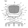
Fig. 2 is a front view thereof. -
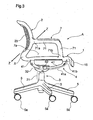
Fig. 3 is a left side view thereof. -
Fig. 4 is a longitudinal cross-sectional view thereof. -
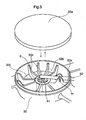
Fig. 5 is a perspective view showing an internal structure of a diameter expanding base part in accordance with this embodiment. -
Fig. 6 is a plain view of the chair in accordance with this embodiment in a state that a mesh member is omitted to show and an upper end cover of a leg support post is removed. -
Fig. 7 is a bottom view of the chair in accordance with this embodiment. -
Fig. 8 is an exploded view ofFig. 4 . -
Fig. 9 is an exploded perspective view of the chair in accordance with this embodiment. -
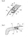
Fig. 10 is a cross-sectional view showing a state that the mesh member is fitted into an opening of the back frame. -
Fig. 11 is a cross-sectional view showing a state that the mesh member is fitted into an opening of the seat frame. -
Fig. 12 is a plain view of the chair in accordance with this embodiment. -
Fig. 13 is a view showing a modified form of this invention. - One embodiment in accordance with the present claimed invention will be described with reference to the accompanying drawings.
- As shown in
Fig. 1 through Fig. 3 , a chair of this embodiment has an arrangement wherein a chair body A comprising aseat 1, aback 2 and anarmrest 7 is supported by aseat support structure 4 rising from a leg body B. - More specifically, the leg body B is so arranged that a
leg support post 3 is rotatably supported by a center part of equiangularly radiating fiveblades 5 each of which has acaster 5a at its distal end. Theleg support post 3 comprises asupport body 31 and a diameter expandingbase part 32 arranged at an upper end of thesupport body 31, and an elevatingmechanism 6 of a gas spring as shown inFig. 4 is incorporated into a part ranging from thesupport body 31 to the diameter expandingbase part 32. The diameter expandingbase part 32 comprises, as shown inFig. 4 andFig. 5 , acover 32a, a bowl-shapedvoid 32b that opens upward when thecover 32a is removed, abottom wall 32c and arib 32d that radially extends upward from a center of thebottom wall 32c, and an inner space is formed above therib 32d so that a finger or a hand can be inserted into the void 32b. A workingportion 61 that locks or unlocks the elevatingmechanism 6 with a projecting or retrojecting movement is accommodated at a center of the diameter expandingbase part 32, an operatinglever 62 as being an operating part is projected toward a radial direction at a position where the workingportion 61 makes an up and down movement through acutout 32x arranged at a part of the diameter expandingbase part 32 and mounted in a pivoted manner on a supporting axis m so as to make an up and down movement around the supporting axis m. Thecover 32a covers the void 32b including the workingportion 61 in a state wherein thecover 32a does not interfere with the operatinglever 62. An operation of lifting the operatinglever 62 makes the workingportion 61 retroject, which frees the elevatingmechanism 6 and an operation of releasing the operation of lifting makes the workingportion 61 project, which locks the elevatingmechanism 6. - Four seat support frames 41 constituting the
seat support structure 4 extend upward from theleg support post 3 and each distal end of the seat support frames 41 supports theseat 1. Theseat support frame 41 comprises ahorizontal part 41a and avertical part 41b each of which is integrally formed, wherein a proximal end of thehorizontal part 41a is connected to a side face of the diameter expandingbase part 32 and the proximal end of thehorizontal part 41a extends toward a side direction to be separated from a center part of theleg support post 3 with gradually bending upward, in other words, extends radially from theleg support post 3 as shown inFig. 6 viewed on a plain view. A load from the above on theseat 1 applies to the rear of the center of theseat 1. Since theleg support post 3 locates in compliance with this, two front seat support frames 41(x) of four seat support frames 41 extending from theleg support post 3 to four corners of theseat 1 are set to be longer than two rear seat support frames 41(y). Thevertical part 41b is, as shown inFig. 4 , smoothly connected to thehorizontal part 41a and a distal end of thevertical part 41b supports an edge part of theseat 1, more concretely, each of undersurfaces seat 1 as shown inFig. 7 . Ascrew inserting part 41c is arranged at an inner portion of thevertical part 41b along a vertical direction as shown inFig. 8 , and thescrew inserting part 41c opens downward at a portion where thehorizontal part 41a crosses thevertical part 41b. A cross-sectional view of theseat support frame 41 is of a flat oval shape whose size is so far forth as an adult with an average build can just grasp at an arbitrary position along the extending direction. - As mentioned above, since the seat support frames 41 radially extend to the four corners of the
seat 1, portions locating below theseat 1 and locating between each of the mutually adjacent seat support frames 41, 41, more concretely, areas A1, A2, A2, A3 of a general triangle shape viewed from the bottom, each of which locates at a front of below theseat 1, right and left sides of below theseat 1, and a back of below theseat 1 respectively are open spaces where no frame exists. In this embodiment, the areas are set to be function adjusting spaces where the operating part is arranged (hereinafter the same codes A1, A2, A2, A3 as those of the above-mentioned areas are given to the function adjusting spaces) and the operatinglever 62 is arranged in the function adjusting space A2 locating at the right side of below theseat 1 viewed from a seated position. - The chair body A comprises, as shown in
Fig. 1 ,Fig. 3 andFig. 9 , theseat 1, theback 2 and thearm rest 7, and supported by theseat support structure 4 without using a back support rod, wherein ascrew fastening part 11 into which a nut member is inserted as shown inFig. 7 andFig. 8 is arranged to hang at a position corresponding to each seat support frames 41 on the undersurface of theseat 1. Theseat 1 is mounted on the seat support frames 41 by placing theseat 1 on each of the upper ends of the seat support frames 41 and then fastening a screw V1 inserted upward from beneath into thescrew inserting part 41c of theseat support frame 41 until the screw V1 reaches thescrew fastening part 11 arranged on theseat 1. - More specifically, this chair has an arrangement wherein each of the distal end parts of the seat support frames 41 constituting the
seat support structure 4 is connected by each side of theseat frame 12 so as to form a frame structure three-dimensionally closed by the seat support frames 41 and theseat frame 12. This arrangement makes it possible to secure the strength of the chair as a whole so as not to be transformed due to impact or weight at a time of being seated even though the seat support frames 41 and theseat frame 12 are formed relatively thin. - As shown in
Fig. 1 andFig. 9 , theseat 1 is so arranged that anopening 12a of inside theseat frame 12 is covered with tension by amesh member 13 and theback 2 is so arranged that anopening 22a of inside theback frame 22 is covered with tension by amesh member 23. A longitudinal rib arranged at a position to reinforce between theseat frame 12 and theback frame 22 is formed to extend toward a side direction significantly so that it can be used as thearm frame 71 so as to be thearm rest 7. Then theseat frame 12, theback frame 22 and thearm frame 71 are made of resin and integrally formed three-dimensionally. - More concretely, as shown in
Fig. 1 andFig. 2 , the valid supportingpart 22b that warps upward from a lumbarcorresponding part 22d most projecting forward of theback frame 22 and theseat frame 12 are set to have generally the same width, ahip corresponding part 22c locating at a portion recessed along downward is gradually narrowed along downward, and a width of a boundary part X between theseat 1 and theback 2 is set to be smaller than a width of the valid supportingpart 22b of theback frame 22 and a width of theseat frame 12. Arear end 71a of thearm frame 71 is formed to extend to a front side direction from theback frame 22 and afront end 71b of thearm frame 71 is formed to extend to an upper side direction from theseat frame 12, and then a peripheral border of anopening 7a formed by thearm frame 71, theseat frame 12 and theback frame 22 is formed in a curved shape not two-dimensionally but three-dimensionally, and whole of the arm frame, the seat frame and the back frame is integrally made of resin. More specifically, theopening 7a can be seen from not only a side view ofFig. 3 but also a front view ofFig. 2 , a plain view ofFig. 6 and a bottom view ofFig. 7 . The boundary part X between theseat 1 and theback 2 is, as shown inFig. 8 , of a continuous three-dimensional shape with a shape of a U-character whose opening faces forward in a longitudinal sectional view and its longitudinal sectional view forming a concave shape whose opening faces forward in a plain view and curving gently along a hip of a seated person. In addition, afront hanging part 15 is arranged at a front end of theseat 1. The front hangingpart 15 is continuously arranged to theseat 1 to form a general reverse L-character in a longitudinal sectional shape as shown inFig. 4 and its longitudinal sectional view forms a continuous three-dimensional shape with curving gently and projecting toward the front in a bottom view. - As shown in
Fig. 1 andFig. 2 , therear end 71a of thearm frame 7 is placed at generally the same height as that of the lumbarcorresponding part 22d so that therear end 71a is continuous to an end of theback frame 22, theback 2 is curved to form a concave shape facing the front in a plain view and the end of theback frame 22 faces the front side direction. Then therear end 71a of thearm frame 7 also is formed to extend forward with making a gentle curve after extending toward the front side direction from theback frame 22. In addition, thefront end 71b of thearm frame 71 is placed to be continuous to an end of theseat frame 12, theseat frame 12 is of a concave shape facing upward slightly in a front view and an end of theseat frame 12 faces toward upward and side direction slightly from a horizontal line. Then thefront end 71b of thearm frame 71 also is formed to rise upward with making a gentle curve after extending from theseat frame 12 toward upward and side direction slightly from the horizontal line. Both a portion that extends to a front side direction from theback frame 22 and a portion that rises from theseat frame 12 are continuous to each of the upper ends of thearm frame 71 that horizontally extends back and forth. These arm frames 71 serve as a longitudinal rib for both theseat frame 12 and theback frame 22 from a viewpoint of a rib. And ahorizontal part 71c is smoothly folded to be continuous to the upper end of thearm frame 71. A direction to break a master block in forming the chair body A is set as a direction of 45 degrees as being a general intermediate angle between the back and forth direction and the up and down direction (an arrow Z inFig. 3 ). - As shown in
Fig. 1 andFig. 9 , themesh member opening seat frame 12 or inside theback frame 22 through a mountingframe - As shown in
Fig. 9 andFig. 10 , at an opening edge of theback frame 22 arranged is a framemember mounting part 122. At a front face of the framemember mounting part 122 provided is a framemember mounting face 122a and at its back face provided is agroove 122b into which a plate shaped body is fitted. The mountingframe 120 in which themesh member 23 is entangled is fitted into the front face of the framemember mounting part 122, and the mountingframe 120 is fastened with a screw V2 that is inserted into the framemember mounting part 122 of theback frame 22 from its back face, and then adecorative frame 121 is fitted into a position to cover the screw V2. On the mountingframe 120 formed is a supportingface 120a that bows toward a direction to gradually narrow its opening width with themesh member 23 receiving a load. - In addition, as shown in
Fig. 9 andFig. 11 , a framemember mounting part 112 having a framemember mounting face 112a at its upper face is arranged at an opening edge of theseat frame 12, the mountingframe 110 in which themesh member 13 is entangled is fitted into an upper face of the framemember mounting part 112, and a screw V3 that is inserted into theseat frame 12 from its bottom face is fastened with the mountingframe 110. On the mountingframe 110 formed is a supportingface 110a that bows toward a direction to gradually narrow its opening width with themesh member 13 receiving a load. - As mentioned above, this embodiment forms the chair shown in
Fig. 1 and a three-dimensional space S is formed at least between the upper end of theleg support post 3 and theseat 1 wherein a dimension d is a sum of a length of thevertical part 41b of theseat support frame 41 and a length of thescrew fastening part 11 that hangs from theseat frame 12 as shown inFig. 4 andFig. 8 , which allows theseat 1 to sink into the space S with bowing as shown by a broken line inFig. 4 due to the load applied to theseat 1 from the above. A size of the space S is so set that an operator can mount or dismount thecover 32a by inserting his or her hand and fingers and a tool, if necessary, at least at a time when no one sits on this chair, and theseat support structure 4 is a frame structure comprising the seat support frames 41. As a result, it is possible to mount or dismount thecover 32a by accessing the hand and fingers from any direction of both the back and front, and the right and left to the space S and to conduct maintenance of the internal workingportion 61. - In addition, this chair has an arrangement that the
seat support structure 4 locating below theseat 1 has multiple seat support frames 41, the workingportion 61 is arranged at the center of theseat support structure 4 and theseat 1 is placed on the seat support frames 41 and fixed to the seat support frames 41 by means of the screws V1 only. As a result, maintenance of the workingpart 61 can be conducted, if necessary, by exposing the workingportion 61 with procedures of separating theseat 1 from theseat support structure 4 by unfastening the screws V1 as shown inFig. 8 and of dismounting thecover 32a. Since theseat 1 is fixed to each of the seat support frames 41 at four points with the screws V1 as shown inFig. 7 , theseat 1 can be swirled horizontally to theseat support structure 4 with its distal end of eachseat support frame 41 kept at generally the same height as shown inFig. 4 andFig. 8 , at a time when the three screws V1 are unfastened, which also enables to expose the workingportion 61. In this case, since theseat 1 is horizontally held by an appropriateseat support frame 41 of theseat support structure 4 at a position after theseat 1 is swirled, maintenance of the workingportion 61 can be conducted without holding theseat 1 by hand. - If this chair is viewed from a visual point of view, the
mesh member 13 set up with tension inside theseat frame 12 forms a translucent area with neither a seat frame of a block shape nor a shell arranged under themesh member 13, and a silhouette of the seat support frames 41 constituting theseat support structure 4 and theblades 5 equiangularly radiating from the proximal portion of the seat support frames 41 can be seen on the seating face as shown inFig. 12 . - As mentioned above, if the inside of the
seat frame 12 is the translucent area, not only a position of the operating part and a number thereof but also a general picture of its function can be visible from the above shown inFig. 12 in case the operating part is arranged in the function adjusting space A1 through A3 inFig. 7 . In this embodiment, the operatinglever 62 of the elevatingmechanism 6 alone is arranged in the function adjusting space A2 locating at a lower right position when seated. As a result, it is easily visible that the operatinglever 62 is arranged at one position alone, the operatinglever 62 locates at the lower right position when seated, the operatinglever 62 extends radially from the upper end of theleg support post 3 and the operatinglever 62 is to operate the elevatingmechanism 6 of a gas spring type. In addition, if an operating part locates in the other function adjusting space A1, A3 shown inFig. 7 , this operating part also can be visible from the above inFig. 12 . This arrangement makes it possible to easily visualize a number of the operating parts, a position thereof, a kind of function thereof or a way to operate the operating parts by making use of its silhouette. - As mentioned above, the chair body A in accordance with this embodiment comprises the
seat frame 12, theback frame 22 and the rib that reinforces between theseat frame 12 and theback frame 22, and the chair body A is not supported by a back support rod. Then the rib is formed to extend toward a side direction so as to be used as anarm frame 71, and theseat frame 12, theback frame 22 and thearm frame 71 are continuously and integrally formed three-dimensionally, and theopening mesh member seat frame 12 and theback frame 22 respectively. - More specifically, for a conventional frame structure with the back and the seat separately arranged, or a conventional frame structure with only the back and the seat integrally formed, a load is applied to a joint or a load is applied only to a single portion, which might cause the joint unjointed, or a crack. However, in accordance with this embodiment, since the
seat frame 12, theback frame 22 and thearm frame 71 are integrally formed, a load applied to the chair body A can be dispersed and reduced. Especially, since theopening back frame 22 and theseat frame 12 respectively, a part of the frame locates at the boundary part X between theseat 1 and theback 2 as being the boundary between theopening 12a and theopening 22a and eachopening mesh member arm frame 71 serves as a longitudinal rib that is generally vertical to the seating face and the back rest face, it becomes more effective to serve as a function of securing the strength. - More concretely, the width of the valid supporting
part 22b locating above the lumbarcorresponding part 22d of theback frame 22 is generally the same as the width of theseat frame 12, thehip corresponding part 22c locating below the lumbarcorresponding part 22d of theback frame 22 is gradually narrowed along downward, and the width of the boundary part X between theseat 1 and theback 2 is set to be smaller than the width of the valid supportingpart 22b of theback 2 and the width of theseat frame 12, the rear end of thearm frame 71 is formed to extend to the front side direction from theback frame 22 and the front end of thearm frame 71 is formed to extend to the upper side direction from theseat frame 12 and then the peripheral border of anopening 7a formed by thearm frame 71, theseat frame 12 and theback frame 22 is formed in a curved shape not two-dimensionally but three-dimensionally, and whole of the arm frame, the seat frame and the back frame is integrally made of resin. - As mentioned, with an arrangement wherein the
arm frame 71, theseat frame 12 and theback frame 22 are three-dimensionally continuous, a stress can be dispersed effectively. As a result of this, it is possible to effectively secure strength as a structure of the chair as well as an amount of the resin to be used can be reduced as much as possible. - In addition, since the boundary part X between the
seat 1 and theback 2 is of a shape of a U-character whose opening faces forward in a longitudinal sectional view and its longitudinal sectional view forms a continuous three-dimensional shape with curving gently along a hip of a seated person in a plain view, it is possible to effectively improve strength of the boundary part X where stress is easily concentrated with taking a form along a body of a seated person. More specifically, since the boundary part X is of the shape of a U-character, a distal end opening of the U-character shape is difficult to be further opened. In addition, since the U-character shape is curved in the plain view, a force toward a direction to open the opening of the U-character shape is difficult to be concentrated on the U-character shape compared with a case wherein a U-character shape is arranged on a straight line in a plain view, thereby to assure the strength more effectively. - Furthermore, since the front hanging
part 15 is arranged at the front end of theseat 1, thefront hanging part 15 is of a general reverse L-character in a longitudinal sectional shape, and its longitudinal sectional view forms a continuous three-dimensional shape with gently curving along the front edge of theseat 1, thefront hanging part 15 of the three-dimensional shape arranged at the front end of theseat 1 contributes to assuring the strength of theseat 1 when a big load is applied to the front end of theseat 1, and a more stable seating state can be assured when a person sits on the chair because thefront hanging part 15 supports a portion ranging from a back side of the knee to the calves of the seated person from behind. Especially, since the front hangingpart 15 is curved in a plain view, an angle of the L-character is difficult to open compared with a case wherein afront hanging part 15 is linear in a plain view, thereby to improve the strength. - The
arm frame 71 serves as a rib by connecting theseat frame 12 and theback frame 22. In addition, since thearm frame 71 has thehorizontal part 71c that is folded toward a direction orthogonal to the direction connecting theseat frame 12 and theback frame 22, thearm frame 71 is difficult to bend compared with an arm frame without a horizontal part, and thehorizontal part 71c assures an enough area where an arm of a seated person contacts. - In addition, since the
arm frame 71 has such a configuration that the end thereof is continuous to the end of theseat frame 12 and extends to the side direction from theseat frame 12 and then smoothly rises upward, it is possible to avoid stress concentrated on the portion connecting theseat frame 12 and thearm frame 71, thereby to effectively prevent unjoint of the connecting portion and crack. This arrangement of no joint also contributes to a smooth appearance. In addition, an arrangement that thearm frame 71 extends to the side direction and then smoothly rises upward generates a margin that enables the seated person to move from side to side to protrude from the seating face to a certain degree with dispersing the stress, which makes it possible for the seated person to take a seating posture with greater freedom. - Furthermore, since the
arm frame 71 has such a configuration that the end thereof is continuous to the end of theback frame 22 and then extends to the front side direction from theback frame 22 with forming a smooth curve, it is possible to avoid stress concentrated also on the portion connecting theback frame 22 and thearm frame 71, thereby to effectively prevent unjoint of the connecting portion and crack. This arrangement of no joint also contributes to a smooth appearance. In addition, an arrangement that thearm frame 71 extends to the front side direction with forming a smooth curve generates a margin that enables the seated person to move from side to side to protrude from the backrest face to a certain degree with dispersing the stress, which makes it possible for the seated person to take a seating posture with greater freedom. - The
rear end 71a of thearm frame 71 is connected to theback frame 22 at the lumbarcorresponding part 22d most protruding forward among a back rest supporting face. Since the lumbarcorresponding part 22d is a portion to which a backrest load applies the most, it is possible to improve the strength of the lumbarcorresponding part 22d by connecting therear end 71a of thearm frame 71 with the lumbarcorresponding part 22d. - Especially, in this embodiment, since the another member comprises a
mesh member face mesh member opening mesh member mesh member mesh member face mesh member seat frame 12 or theback frame 22 more effectively compared with a case of having a movable supporting face. - Furthermore, since the
corner portions seat frame 12 are rotatably supported by theleg support post 3 through the multiple seat support frames 41 that extend radially, it is possible to effectively avoid deformation of theseat frame 12. In addition, this arrangement makes it possible to effectively serve as a swivel chair of a type wherein a seating face is fitted into theopening - A concrete arrangement of each part is not limited to the above-mentioned embodiment.
- For example, in the above embodiment, the
seat frame 12, theback frame 12 and thearm frame 7 are integrally formed of resin, however, a seat frame component and a back frame component, each of which is separated, and an arm frame component that functions as a rib may be connected integrally by the use of connecting members. With this arrangement, each of the seat frame component and the back frame component can be considered as a closed component, certain strength can be obtained by connecting the seat frame component and the back frame component at a boundary part between the seat and the back. In addition, the arm frame component serves as a rib that connects between the seat frame component and the back frame component and the opening of the seat frame component and the opening of the back frame component are covered with tension, it is possible to effectively prevent unjoint of the portion connecting the seat frame component and the back frame component and crack. - Furthermore, based on the premise of integral molding, as long as the rib is formed to extend toward a side direction so as to be used as the arm frame, and the seat frame, the back frame and the arm frame are integrally formed three-dimensionally, a single
big opening 200 may be arranged at a portion ranging from aseat frame 212 to aback frame 222, as shown inFig. 13 , and a mesh member (omitted to show in the drawing) as being the another member to form the seating face may be fitted into theopening 200. With this arrangement also, since theseat frame 212, theback frame 222 and an arm frame 277 that connects between theseat frame 212 and theback frame 222 mutually reinforce three-dimensionally and theopening 200 at the portion ranging from aseat frame 212 to aback frame 222 is covered with tension, it is possible to effectively prevent unjoint of the connecting portion and crack. - Other arrangement may be variously modified without departing from the scope of the invention as defined in the appended claims.
- For example, the seating face may be transparent or translucent made of acrylic material in stead of the mesh member. This arrangement produces the same effect visually as that of the above-mentioned embodiment.
- The present claimed invention intends to provide a chair having a frame structure that is effective for securing a required strength without needless structure to reinforce the strength.
- The chair has a chair body A comprising a
seat frame 12, aback frame 22 and a rib that reinforces between theseat frame 12 and theback frame 22, wherein the rib is formed to extend to a side direction so as to be used as anarm frame 71, and theseat frame 12, theback frame 22 and thearm frame 71 are continuously and integrally formed three-dimensionally, andopenings mesh member seat frame 12 and theback frame 22 respectively.
Claims (10)
- A chair, wherein
a chair body (A) comprises a seat frame (12; 212), a back frame (22; 222) and a rib (71; 271) that reinforces between the seat frame (12; 212) and the back frame (22; 222), the rib (71; 271) is formed to extend to a side direction so as to be used as an arm frame (71; 271),
the seat frame (12; 212), the back frame (22; 222) and the arm frame (71; 271) are continuously and integrally formed three-dimensionally,
a single opening (200) into which another member (13; 23) to form a seating face is fitted is arranged at a portion ranging from the seat frame (212) to the back frame (222), or an opening (12a; 22a) into which another member (13; 23) to form a seating face is fitted is arranged at the seat frame (12) and the back frame (22) respectively,
a rear end (71a) of the arm frame (71; 271) is formed to extend to a front side direction from the back frame (22; 222),
a front end (71b) of the arm frame (71; 271) is formed to extend to an upper side direction from the seat frame (12; 212), and
whole of the arm frame (71; 271), the seat frame (12; 212) and the back frame (22; 222) is integrally made of resin,
characterized in that
a peripheral border of an opening (7a) formed by the arm frame (71; 271), the seat frame (12; 212) and the back frame (22; 222) is curved three-dimensionally such that said opening (7a) is visible in each of a side view, a front view, a plan view and a bottom view of the chair. - The chair according to claim 1, wherein
a width of a valid supporting part (22b) locating above a lumbar corresponding part (22d) of the back frame (22; 222) is generally the same as a width of the seat frame (12; 212),
a hip corresponding part (22c) locating below the lumbar corresponding part (22d) of the back frame (22; 222) is gradually narrowed along downward, and
a width of a boundary part (X) between the back frame (22; 222) and the seat frame (12; 212) is set to be smaller than a width of the valid supporting part (22b) of the back frame and a width of the seat frame (12; 212). - The chair according to claim 1 or 2, wherein a boundary part (X) between a seat (1) and a back (2) is of a shape of U-character whose opening faces forward in a longitudinal sectional view, and its longitudinal sectional view forms a continuous three-dimensional shape with curving gently along a hip in a plain view.
- The chair according to claims 1 to 3, wherein a front hanging part (15) is arranged at a front end of a seat (1), the front hanging part (15) is of a reverse L-character in a longitudinal sectional view, and its longitudinal sectional view forms a continuous three-dimensional shape with gently curving along a front edge of the seat (1).
- The chair according to claims 1 to 4, wherein a horizontal part (71c) is continuously arranged in a smoothly folded manner at an upper end of the arm frame (71; 271).
- The chair according to claims 1 to 5, wherein the arm frame (71; 271) has such a configuration that an end thereof is continuous to an end of the seat frame (12; 212) and extends to a side direction from the seat frame (12; 212) and then smoothly rises upward.
- The chair according to claims 1 to 6, wherein the arm frame (71; 271) has such a configuration that an end thereof is continuous to an end of the back frame (22; 222) and extends to a front side direction from the back frame (22; 222) with forming a smooth curve.
- The chair according to claims 1 to 7, wherein one end of the arm frame (71; 271) is connected to the back frame (22; 222) at a height generally the same as a height of a lumbar corresponding part (22d) most protruding forward among a back rest supporting face.
- The chair according to claims 1 to 8, wherein the another member (13; 23) comprises a mesh member (13; 23), a supporting face (110a; 120a) having a curved surface that supports the mesh member (13; 23) is arranged at an edge of the opening (12a; 22a), and when the mesh member (13; 23) receives a load the curved surface supports the load through the mesh member (13; 23) with the mesh member (13; 23) smoothly bowing along the curved surface.
- The chair according to claims 1 to 9, wherein corner portions (1a, 1b) of the seat frame (12; 212) are rotatably supported by a leg support post (3) through multiple seat support frames (41) that extend radially.
Applications Claiming Priority (1)
| Application Number | Priority Date | Filing Date | Title |
|---|---|---|---|
| JP2006088777A JP5263802B2 (en) | 2006-03-28 | 2006-03-28 | Chair |
Publications (2)
| Publication Number | Publication Date |
|---|---|
| EP1839532A1 EP1839532A1 (en) | 2007-10-03 |
| EP1839532B1 true EP1839532B1 (en) | 2009-06-10 |
Family
ID=38055324
Family Applications (1)
| Application Number | Title | Priority Date | Filing Date |
|---|---|---|---|
| EP07104023A Expired - Fee Related EP1839532B1 (en) | 2006-03-28 | 2007-03-13 | Chair |
Country Status (6)
| Country | Link |
|---|---|
| US (1) | US7654616B2 (en) |
| EP (1) | EP1839532B1 (en) |
| JP (1) | JP5263802B2 (en) |
| CN (1) | CN101044942A (en) |
| AT (1) | ATE433292T1 (en) |
| DE (1) | DE602007001253D1 (en) |
Families Citing this family (32)
| Publication number | Priority date | Publication date | Assignee | Title |
|---|---|---|---|---|
| ES2388713T3 (en) | 2008-05-26 | 2012-10-17 | Steelcase Inc. | Adjustable backrest for a seat unit |
| US7841664B2 (en) | 2008-06-04 | 2010-11-30 | Steelcase Inc. | Chair with control system |
| US7887138B2 (en) * | 2009-01-23 | 2011-02-15 | Chen Yung-Hua | Integrally formed base arrangement of an office chair |
| US20110057497A1 (en) * | 2009-09-08 | 2011-03-10 | Tsan-Ching Wang | Combination of net and frame |
| USD667232S1 (en) * | 2011-03-12 | 2012-09-18 | Jianhua Yang | Office chair |
| JP5905708B2 (en) * | 2011-11-04 | 2016-04-20 | 株式会社岡村製作所 | Tension material tensioning method and tension material tension structure |
| US9192236B2 (en) | 2012-07-27 | 2015-11-24 | Kgm Gaming Llc | Guard and combination for rotatable or swivel seat and method of installing same |
| US20140054947A1 (en) * | 2012-08-22 | 2014-02-27 | Tung-Hua Su | Backrest assembly with front and rear frames |
| US20150021971A1 (en) * | 2013-07-19 | 2015-01-22 | Minson Corporation | Internal support for a backrest for a chair |
| USD696545S1 (en) | 2013-07-30 | 2013-12-31 | Steelcase, Inc. | Rear surface of a chair back |
| TWM483731U (en) * | 2013-12-31 | 2014-08-11 | Yong-Hua Chen | Office chair |
| USD731801S1 (en) | 2014-06-12 | 2015-06-16 | Steelcase Inc. | Chair |
| USD731802S1 (en) | 2014-06-12 | 2015-06-16 | Steelcase Inc. | Chair |
| US9167902B1 (en) * | 2014-07-01 | 2015-10-27 | Yung-hua Chen | One-piece office chair in three dimensions |
| US11259637B2 (en) | 2015-04-13 | 2022-03-01 | Steelcase Inc. | Seating arrangement |
| CA2981528A1 (en) | 2015-04-13 | 2016-10-20 | Steelcase Inc. | Seating arrangement |
| US10194750B2 (en) | 2015-04-13 | 2019-02-05 | Steelcase Inc. | Seating arrangement |
| US10966527B2 (en) | 2017-06-09 | 2021-04-06 | Steelcase Inc. | Seating arrangement and method of construction |
| US10463153B2 (en) | 2016-06-09 | 2019-11-05 | Steelcase Inc. | Seating arrangement |
| US10561249B2 (en) | 2017-05-23 | 2020-02-18 | Yeti Coolers, Llc | Portable chair and cup holder assembly |
| US10194749B1 (en) | 2017-05-23 | 2019-02-05 | Yeti Coolers, Llc | Portable chair and methods of forming a portable chair |
| US10743670B2 (en) | 2017-05-23 | 2020-08-18 | Yeti Coolers, Llc | Portable chair and cup holder assembly |
| JP6958211B2 (en) | 2017-10-12 | 2021-11-02 | トヨタ自動車株式会社 | Vehicle seat |
| USD850810S1 (en) | 2018-01-10 | 2019-06-11 | Yeti Coolers, Llc | Portable chair |
| USD843150S1 (en) | 2018-01-10 | 2019-03-19 | Yeti Coolers, Llc | Portable chair |
| USD843152S1 (en) | 2018-01-10 | 2019-03-19 | Yeti Coolers, Llc | Portable chair |
| USD843151S1 (en) | 2018-01-10 | 2019-03-19 | Yeti Coolers, Llc | Portable chair |
| CN109008364B (en) * | 2018-08-23 | 2021-05-11 | 王敏雪 | Multifunctional swinging type cooling device |
| US10617226B1 (en) * | 2019-01-07 | 2020-04-14 | Wen Hsien Liao | Backrest and seat of a chair |
| US11109683B2 (en) | 2019-02-21 | 2021-09-07 | Steelcase Inc. | Body support assembly and method for the use and assembly thereof |
| US11357329B2 (en) | 2019-12-13 | 2022-06-14 | Steelcase Inc. | Body support assembly and methods for the use and assembly thereof |
| US11690457B2 (en) | 2020-02-04 | 2023-07-04 | Hni Technologies Inc. | Chair with flexible internal support |
Family Cites Families (24)
| Publication number | Priority date | Publication date | Assignee | Title |
|---|---|---|---|---|
| GB615796A (en) | 1946-08-02 | 1949-01-12 | Charles Vincent Morris | Improvements in or relating to easy chairs, arm chairs or the like |
| US2731078A (en) * | 1949-07-30 | 1956-01-17 | Harry H Cadman | Furniture construction |
| US3441310A (en) * | 1963-03-27 | 1969-04-29 | Gale Co John | Seating structure |
| US3756656A (en) * | 1972-02-04 | 1973-09-04 | J Weick | Chair |
| USD255185S (en) * | 1977-07-15 | 1980-06-03 | Giroflex-Entwicklungs-Ag | Chair or similar article |
| US4361357A (en) * | 1980-04-21 | 1982-11-30 | Pollock Charles R | Chair |
| DE8135614U1 (en) * | 1981-12-07 | 1983-11-10 | Gebr. Thonet GmbH, 6000 Frankfurt | SEAT FURNITURE |
| US4598892A (en) * | 1984-07-27 | 1986-07-08 | Haworth, Inc. | Mechanical chair-height control mechanism |
| JPS62139355U (en) * | 1986-02-27 | 1987-09-02 | ||
| FR2619496B1 (en) * | 1987-08-18 | 1991-05-10 | Massonnet Henry | SOFT BACK ARMCHAIR |
| FR2638076B1 (en) * | 1989-03-01 | 1991-02-01 | Grosfillex Sarl | MONOLITHIC SEAT IN INJECTED PLASTIC MATERIAL |
| EP0364309B1 (en) * | 1989-03-01 | 1993-02-10 | Grosfillex S.A.R.L. | One-shell extruded plastic armchair stackable in a compact manner |
| USD341953S (en) * | 1991-11-21 | 1993-12-07 | Bemis Manufacturing Company | Dining chair |
| WO1993025121A1 (en) * | 1992-06-15 | 1993-12-23 | Herman Miller, Inc. | Office chair |
| USD364748S (en) * | 1994-05-11 | 1995-12-05 | Syroco, Inc. | Armchair |
| JPH0810084A (en) | 1994-07-01 | 1996-01-16 | Takano Co Ltd | Chair |
| US6702391B1 (en) | 1995-06-07 | 2004-03-09 | Grant Stipek | Furniture with molded frame |
| FR2746279B1 (en) * | 1996-03-19 | 1998-05-07 | Stamp Sa | SWIVEL ARMCHAIR |
| JP4040744B2 (en) | 1998-03-26 | 2008-01-30 | 株式会社岡村製作所 | Chair seat mounting structure |
| USD416700S (en) * | 1999-02-16 | 1999-11-23 | Euro United Corporation | Stackable chair with squared back |
| USD419325S (en) * | 1999-02-16 | 2000-01-25 | Euro United Corporation | Stackable chair with rounded back |
| USD431922S (en) * | 1999-05-17 | 2000-10-17 | Grosfillex Sarl | Armchair |
| DE20010342U1 (en) | 2000-06-09 | 2000-08-31 | Kettler Heinz Gmbh | armchair |
| JP2003144264A (en) * | 2001-11-16 | 2003-05-20 | Kokuyo Co Ltd | Chair |
-
2006
- 2006-03-28 JP JP2006088777A patent/JP5263802B2/en active Active
- 2006-11-28 CN CNA2006101627631A patent/CN101044942A/en active Pending
-
2007
- 2007-03-13 DE DE602007001253T patent/DE602007001253D1/en active Active
- 2007-03-13 EP EP07104023A patent/EP1839532B1/en not_active Expired - Fee Related
- 2007-03-13 AT AT07104023T patent/ATE433292T1/en active
- 2007-03-21 US US11/723,592 patent/US7654616B2/en not_active Expired - Fee Related
Also Published As
| Publication number | Publication date |
|---|---|
| US7654616B2 (en) | 2010-02-02 |
| JP5263802B2 (en) | 2013-08-14 |
| US20070228799A1 (en) | 2007-10-04 |
| JP2007260118A (en) | 2007-10-11 |
| ATE433292T1 (en) | 2009-06-15 |
| DE602007001253D1 (en) | 2009-07-23 |
| EP1839532A1 (en) | 2007-10-03 |
| CN101044942A (en) | 2007-10-03 |
Similar Documents
| Publication | Publication Date | Title |
|---|---|---|
| EP1839532B1 (en) | Chair | |
| EP1839529A1 (en) | Chair | |
| JP2592108B2 (en) | Chair with backrest | |
| JP4477766B2 (en) | Chair backboard | |
| JP5529502B2 (en) | Chair | |
| KR102130324B1 (en) | Assembly and chair with the same | |
| JP5524578B2 (en) | Chair backrest device | |
| JP4844723B2 (en) | Chair | |
| JP5078450B2 (en) | Chair | |
| JP2006149751A (en) | Body support | |
| KR100772167B1 (en) | A chair having backrest | |
| JP5490175B2 (en) | Chair | |
| JP5013359B2 (en) | Chair | |
| JP2012176259A5 (en) | ||
| JP5529501B2 (en) | Chair | |
| JP5024778B2 (en) | Chair | |
| JP4427178B2 (en) | Backboard mounting structure for chairs | |
| JP4884666B2 (en) | Chair | |
| JP4486465B2 (en) | Chair backrest mounting structure | |
| JP6705879B2 (en) | Chair | |
| JP7299004B2 (en) | Chair | |
| KR200318489Y1 (en) | Bone structure of chair having integrated headrest frame | |
| JP5490172B2 (en) | Chair | |
| JP4119332B2 (en) | Chair with armrests | |
| JP3729326B2 (en) | Chair |
Legal Events
| Date | Code | Title | Description |
|---|---|---|---|
| PUAI | Public reference made under article 153(3) epc to a published international application that has entered the european phase |
Free format text: ORIGINAL CODE: 0009012 |
|
| AK | Designated contracting states |
Kind code of ref document: A1 Designated state(s): AT BE BG CH CY CZ DE DK EE ES FI FR GB GR HU IE IS IT LI LT LU LV MC MT NL PL PT RO SE SI SK TR |
|
| AX | Request for extension of the european patent |
Extension state: AL BA HR MK YU |
|
| RAP1 | Party data changed (applicant data changed or rights of an application transferred) |
Owner name: KOKUYO FURNITURE CO., LTD. |
|
| 17P | Request for examination filed |
Effective date: 20071217 |
|
| 17Q | First examination report despatched |
Effective date: 20080128 |
|
| AKX | Designation fees paid |
Designated state(s): AT DE FR GB |
|
| GRAP | Despatch of communication of intention to grant a patent |
Free format text: ORIGINAL CODE: EPIDOSNIGR1 |
|
| GRAS | Grant fee paid |
Free format text: ORIGINAL CODE: EPIDOSNIGR3 |
|
| GRAA | (expected) grant |
Free format text: ORIGINAL CODE: 0009210 |
|
| AK | Designated contracting states |
Kind code of ref document: B1 Designated state(s): AT DE FR GB |
|
| REG | Reference to a national code |
Ref country code: GB Ref legal event code: FG4D |
|
| REF | Corresponds to: |
Ref document number: 602007001253 Country of ref document: DE Date of ref document: 20090723 Kind code of ref document: P |
|
| PLBE | No opposition filed within time limit |
Free format text: ORIGINAL CODE: 0009261 |
|
| STAA | Information on the status of an ep patent application or granted ep patent |
Free format text: STATUS: NO OPPOSITION FILED WITHIN TIME LIMIT |
|
| 26N | No opposition filed |
Effective date: 20100311 |
|
| PGFP | Annual fee paid to national office [announced via postgrant information from national office to epo] |
Ref country code: FR Payment date: 20120319 Year of fee payment: 6 |
|
| PGFP | Annual fee paid to national office [announced via postgrant information from national office to epo] |
Ref country code: GB Payment date: 20120307 Year of fee payment: 6 |
|
| PGFP | Annual fee paid to national office [announced via postgrant information from national office to epo] |
Ref country code: DE Payment date: 20120411 Year of fee payment: 6 |
|
| PGFP | Annual fee paid to national office [announced via postgrant information from national office to epo] |
Ref country code: AT Payment date: 20120228 Year of fee payment: 6 |
|
| REG | Reference to a national code |
Ref country code: AT Ref legal event code: MM01 Ref document number: 433292 Country of ref document: AT Kind code of ref document: T Effective date: 20130313 |
|
| GBPC | Gb: european patent ceased through non-payment of renewal fee |
Effective date: 20130313 |
|
| REG | Reference to a national code |
Ref country code: FR Ref legal event code: ST Effective date: 20131129 |
|
| REG | Reference to a national code |
Ref country code: DE Ref legal event code: R119 Ref document number: 602007001253 Country of ref document: DE Effective date: 20131001 |
|
| PG25 | Lapsed in a contracting state [announced via postgrant information from national office to epo] |
Ref country code: DE Free format text: LAPSE BECAUSE OF NON-PAYMENT OF DUE FEES Effective date: 20131001 Ref country code: GB Free format text: LAPSE BECAUSE OF NON-PAYMENT OF DUE FEES Effective date: 20130313 Ref country code: AT Free format text: LAPSE BECAUSE OF NON-PAYMENT OF DUE FEES Effective date: 20130313 Ref country code: FR Free format text: LAPSE BECAUSE OF NON-PAYMENT OF DUE FEES Effective date: 20130402 |
|
| P01 | Opt-out of the competence of the unified patent court (upc) registered |
Effective date: 20230426 |