EP1832095B1 - A mobile terminal, and associated methods, with improved user interface - Google Patents
A mobile terminal, and associated methods, with improved user interface Download PDFInfo
- Publication number
- EP1832095B1 EP1832095B1 EP05814278A EP05814278A EP1832095B1 EP 1832095 B1 EP1832095 B1 EP 1832095B1 EP 05814278 A EP05814278 A EP 05814278A EP 05814278 A EP05814278 A EP 05814278A EP 1832095 B1 EP1832095 B1 EP 1832095B1
- Authority
- EP
- European Patent Office
- Prior art keywords
- mobile terminal
- display
- input device
- way input
- joystick
- Prior art date
- Legal status (The legal status is an assumption and is not a legal conclusion. Google has not performed a legal analysis and makes no representation as to the accuracy of the status listed.)
- Not-in-force
Links
Images


Classifications
-
- G—PHYSICS
- G06—COMPUTING; CALCULATING OR COUNTING
- G06F—ELECTRIC DIGITAL DATA PROCESSING
- G06F1/00—Details not covered by groups G06F3/00 - G06F13/00 and G06F21/00
- G06F1/16—Constructional details or arrangements
- G06F1/1613—Constructional details or arrangements for portable computers
- G06F1/1626—Constructional details or arrangements for portable computers with a single-body enclosure integrating a flat display, e.g. Personal Digital Assistants [PDAs]
-
- G—PHYSICS
- G06—COMPUTING; CALCULATING OR COUNTING
- G06F—ELECTRIC DIGITAL DATA PROCESSING
- G06F1/00—Details not covered by groups G06F3/00 - G06F13/00 and G06F21/00
- G06F1/16—Constructional details or arrangements
- G06F1/1613—Constructional details or arrangements for portable computers
- G06F1/1615—Constructional details or arrangements for portable computers with several enclosures having relative motions, each enclosure supporting at least one I/O or computing function
- G06F1/1616—Constructional details or arrangements for portable computers with several enclosures having relative motions, each enclosure supporting at least one I/O or computing function with folding flat displays, e.g. laptop computers or notebooks having a clamshell configuration, with body parts pivoting to an open position around an axis parallel to the plane they define in closed position
-
- G—PHYSICS
- G06—COMPUTING; CALCULATING OR COUNTING
- G06F—ELECTRIC DIGITAL DATA PROCESSING
- G06F1/00—Details not covered by groups G06F3/00 - G06F13/00 and G06F21/00
- G06F1/16—Constructional details or arrangements
- G06F1/1613—Constructional details or arrangements for portable computers
- G06F1/1633—Constructional details or arrangements of portable computers not specific to the type of enclosures covered by groups G06F1/1615 - G06F1/1626
- G06F1/1637—Details related to the display arrangement, including those related to the mounting of the display in the housing
- G06F1/1647—Details related to the display arrangement, including those related to the mounting of the display in the housing including at least an additional display
- G06F1/165—Details related to the display arrangement, including those related to the mounting of the display in the housing including at least an additional display the additional display being small, e.g. for presenting status information
-
- G—PHYSICS
- G06—COMPUTING; CALCULATING OR COUNTING
- G06F—ELECTRIC DIGITAL DATA PROCESSING
- G06F1/00—Details not covered by groups G06F3/00 - G06F13/00 and G06F21/00
- G06F1/16—Constructional details or arrangements
- G06F1/1613—Constructional details or arrangements for portable computers
- G06F1/1633—Constructional details or arrangements of portable computers not specific to the type of enclosures covered by groups G06F1/1615 - G06F1/1626
- G06F1/1684—Constructional details or arrangements related to integrated I/O peripherals not covered by groups G06F1/1635 - G06F1/1675
- G06F1/1698—Constructional details or arrangements related to integrated I/O peripherals not covered by groups G06F1/1635 - G06F1/1675 the I/O peripheral being a sending/receiving arrangement to establish a cordless communication link, e.g. radio or infrared link, integrated cellular phone
-
- G—PHYSICS
- G06—COMPUTING; CALCULATING OR COUNTING
- G06F—ELECTRIC DIGITAL DATA PROCESSING
- G06F3/00—Input arrangements for transferring data to be processed into a form capable of being handled by the computer; Output arrangements for transferring data from processing unit to output unit, e.g. interface arrangements
- G06F3/01—Input arrangements or combined input and output arrangements for interaction between user and computer
- G06F3/02—Input arrangements using manually operated switches, e.g. using keyboards or dials
- G06F3/023—Arrangements for converting discrete items of information into a coded form, e.g. arrangements for interpreting keyboard generated codes as alphanumeric codes, operand codes or instruction codes
- G06F3/0233—Character input methods
- G06F3/0236—Character input methods using selection techniques to select from displayed items
-
- G—PHYSICS
- G06—COMPUTING; CALCULATING OR COUNTING
- G06F—ELECTRIC DIGITAL DATA PROCESSING
- G06F3/00—Input arrangements for transferring data to be processed into a form capable of being handled by the computer; Output arrangements for transferring data from processing unit to output unit, e.g. interface arrangements
- G06F3/01—Input arrangements or combined input and output arrangements for interaction between user and computer
- G06F3/03—Arrangements for converting the position or the displacement of a member into a coded form
- G06F3/033—Pointing devices displaced or positioned by the user, e.g. mice, trackballs, pens or joysticks; Accessories therefor
- G06F3/0338—Pointing devices displaced or positioned by the user, e.g. mice, trackballs, pens or joysticks; Accessories therefor with detection of limited linear or angular displacement of an operating part of the device from a neutral position, e.g. isotonic or isometric joysticks
-
- G—PHYSICS
- G06—COMPUTING; CALCULATING OR COUNTING
- G06F—ELECTRIC DIGITAL DATA PROCESSING
- G06F3/00—Input arrangements for transferring data to be processed into a form capable of being handled by the computer; Output arrangements for transferring data from processing unit to output unit, e.g. interface arrangements
- G06F3/01—Input arrangements or combined input and output arrangements for interaction between user and computer
- G06F3/048—Interaction techniques based on graphical user interfaces [GUI]
- G06F3/0481—Interaction techniques based on graphical user interfaces [GUI] based on specific properties of the displayed interaction object or a metaphor-based environment, e.g. interaction with desktop elements like windows or icons, or assisted by a cursor's changing behaviour or appearance
-
- G—PHYSICS
- G06—COMPUTING; CALCULATING OR COUNTING
- G06F—ELECTRIC DIGITAL DATA PROCESSING
- G06F3/00—Input arrangements for transferring data to be processed into a form capable of being handled by the computer; Output arrangements for transferring data from processing unit to output unit, e.g. interface arrangements
- G06F3/01—Input arrangements or combined input and output arrangements for interaction between user and computer
- G06F3/048—Interaction techniques based on graphical user interfaces [GUI]
- G06F3/0487—Interaction techniques based on graphical user interfaces [GUI] using specific features provided by the input device, e.g. functions controlled by the rotation of a mouse with dual sensing arrangements, or of the nature of the input device, e.g. tap gestures based on pressure sensed by a digitiser
- G06F3/0488—Interaction techniques based on graphical user interfaces [GUI] using specific features provided by the input device, e.g. functions controlled by the rotation of a mouse with dual sensing arrangements, or of the nature of the input device, e.g. tap gestures based on pressure sensed by a digitiser using a touch-screen or digitiser, e.g. input of commands through traced gestures
- G06F3/04886—Interaction techniques based on graphical user interfaces [GUI] using specific features provided by the input device, e.g. functions controlled by the rotation of a mouse with dual sensing arrangements, or of the nature of the input device, e.g. tap gestures based on pressure sensed by a digitiser using a touch-screen or digitiser, e.g. input of commands through traced gestures by partitioning the display area of the touch-screen or the surface of the digitising tablet into independently controllable areas, e.g. virtual keyboards or menus
-
- H—ELECTRICITY
- H04—ELECTRIC COMMUNICATION TECHNIQUE
- H04M—TELEPHONIC COMMUNICATION
- H04M1/00—Substation equipment, e.g. for use by subscribers
- H04M1/72—Mobile telephones; Cordless telephones, i.e. devices for establishing wireless links to base stations without route selection
- H04M1/724—User interfaces specially adapted for cordless or mobile telephones
- H04M1/72403—User interfaces specially adapted for cordless or mobile telephones with means for local support of applications that increase the functionality
-
- H—ELECTRICITY
- H04—ELECTRIC COMMUNICATION TECHNIQUE
- H04M—TELEPHONIC COMMUNICATION
- H04M1/00—Substation equipment, e.g. for use by subscribers
- H04M1/02—Constructional features of telephone sets
- H04M1/0202—Portable telephone sets, e.g. cordless phones, mobile phones or bar type handsets
- H04M1/0206—Portable telephones comprising a plurality of mechanically joined movable body parts, e.g. hinged housings
- H04M1/0208—Portable telephones comprising a plurality of mechanically joined movable body parts, e.g. hinged housings characterized by the relative motions of the body parts
- H04M1/0214—Foldable telephones, i.e. with body parts pivoting to an open position around an axis parallel to the plane they define in closed position
-
- H—ELECTRICITY
- H04—ELECTRIC COMMUNICATION TECHNIQUE
- H04M—TELEPHONIC COMMUNICATION
- H04M1/00—Substation equipment, e.g. for use by subscribers
- H04M1/02—Constructional features of telephone sets
- H04M1/23—Construction or mounting of dials or of equivalent devices; Means for facilitating the use thereof
- H04M1/233—Construction or mounting of dials or of equivalent devices; Means for facilitating the use thereof including a pointing device, e.g. roller key, track ball, rocker switch or joystick
-
- H—ELECTRICITY
- H04—ELECTRIC COMMUNICATION TECHNIQUE
- H04M—TELEPHONIC COMMUNICATION
- H04M1/00—Substation equipment, e.g. for use by subscribers
- H04M1/60—Substation equipment, e.g. for use by subscribers including speech amplifiers
- H04M1/6033—Substation equipment, e.g. for use by subscribers including speech amplifiers for providing handsfree use or a loudspeaker mode in telephone sets
- H04M1/6041—Portable telephones adapted for handsfree use
- H04M1/6058—Portable telephones adapted for handsfree use involving the use of a headset accessory device connected to the portable telephone
- H04M1/6066—Portable telephones adapted for handsfree use involving the use of a headset accessory device connected to the portable telephone including a wireless connection
-
- H—ELECTRICITY
- H04—ELECTRIC COMMUNICATION TECHNIQUE
- H04M—TELEPHONIC COMMUNICATION
- H04M1/00—Substation equipment, e.g. for use by subscribers
- H04M1/66—Substation equipment, e.g. for use by subscribers with means for preventing unauthorised or fraudulent calling
- H04M1/663—Preventing unauthorised calls to a telephone set
-
- H—ELECTRICITY
- H04—ELECTRIC COMMUNICATION TECHNIQUE
- H04M—TELEPHONIC COMMUNICATION
- H04M1/00—Substation equipment, e.g. for use by subscribers
- H04M1/72—Mobile telephones; Cordless telephones, i.e. devices for establishing wireless links to base stations without route selection
- H04M1/724—User interfaces specially adapted for cordless or mobile telephones
- H04M1/72403—User interfaces specially adapted for cordless or mobile telephones with means for local support of applications that increase the functionality
- H04M1/72442—User interfaces specially adapted for cordless or mobile telephones with means for local support of applications that increase the functionality for playing music files
-
- H—ELECTRICITY
- H04—ELECTRIC COMMUNICATION TECHNIQUE
- H04M—TELEPHONIC COMMUNICATION
- H04M1/00—Substation equipment, e.g. for use by subscribers
- H04M1/72—Mobile telephones; Cordless telephones, i.e. devices for establishing wireless links to base stations without route selection
- H04M1/724—User interfaces specially adapted for cordless or mobile telephones
- H04M1/72466—User interfaces specially adapted for cordless or mobile telephones with selection means, e.g. keys, having functions defined by the mode or the status of the device
-
- H—ELECTRICITY
- H04—ELECTRIC COMMUNICATION TECHNIQUE
- H04M—TELEPHONIC COMMUNICATION
- H04M2250/00—Details of telephonic subscriber devices
- H04M2250/16—Details of telephonic subscriber devices including more than one display unit
Definitions
- the present invention relates to mobile telecommunication and more particularly to improvements in the user interface of a mobile terminal that has a multi-way input device such as a joystick.
- a mobile (cellular) telephone for a telecommunications system like GSM, UMTS, D-AMPS or CDMA2000 is a common example of a mobile terminal according to the above.
- the conventional user interface of mobile telephones were limited to a display, a keypad, a speaker and a microphone.
- the keypad it normally included an alpha-numeric or ITU-T type set of keys (characters "0"-"9", “*", "#”, and a few other keys such as call handling keys for "Call"/"Yes" and "Hangup”/"No".
- ITU-T type set of keys characters "0"-"9", “*", "#”
- call handling keys for "Call"/"Yes" and "Hangup”/"No.
- essentially all non-acoustic user input was entered through the keypad (expect for certain specific control operations that were done through dedicated buttons, such and volume control buttons).
- a keypad as described above has its limitations as regards user-friendliness.
- an ITU-T type keypad sufficed for most users, since the required user interaction was essentially limited to the dialing of telephone numbers and call handling for generating outgoing calls and answering or rejecting incoming calls.
- Modern terminals are used for many other purposes than merely speech communication; electronic messaging, recording of digital pictures or video, listening to FM radio or MP3 music, and electronic games being just a few examples of software applications that are typically used in a contemporary mobile terminal. For such applications, an ITU-T type keypad is clearly insufficient if used as the only input device in the mobile terminal.
- FIG 6 gives a schematic illustration of a prior art mobile terminal having a user interface which includes a display 600 and an ITU-T type keypad 640.
- the latter includes conventional alpha-numeric hard keys 646 as well as left and right soft keys 642, 644.
- a "soft key” is not soft in a physical sense but in a logical; a soft key can and will be assigned different functions in different contexts, so that it may have one meaning in a certain situation in an active application, a completely different meaning in another situation in the same application, and yet other meanings in other applications.
- the hard keys 646 are not harder than the soft keys in a physical sense but normally only has one meaning irrespective of application, e.g. the hard key labeled "1" represents the digit "1" both in call handling and a calendar application as well as in a calculator application.
- a status area 610 at the uppermost part of the display 600 presents general information that is not associated with a particular application, such as date/time, battery level and RSSI (Received Signal Strength Indicator).
- An incoming call is announced as a message 622 in a main presentation area 620.
- a lowermost area 630 of the display 600 shows respective text labels 632 and 634 which indicates the current function or meaning associated with soft keys 642 and 644, respectively.
- the soft key labels 632 and 634 will be assigned other functions, and consequently the text labels 632 and 634 will be updated to reflect this.
- An ITU-T type keypad is not particularly advantageous for navigation and selection among information presented on the display. Since this is frequently required in the various applications available in a modern mobile terminal, it is known in the prior art to provide a mobile terminal with other kinds of input devices instead of or in addition to an ITU-T type keypad, such as a multi-way input device in the form of a joystick or 4-way/5-way navigation key.
- a multi-way input device is advantageous for two reasons: it is physically compact and therefore conforms well to modern demands for miniaturization, and it represents an intuitive and easily operated means for navigating and selecting among information presented on the mobile terminal's display.
- the Nokia® 7650 has, in addition to a retractable ITU-T keypad, a joystick placed between two soft keys. The joystick is used as a means for scrolling in lists and among user interface objects such as icons and menu items.
- the primary display is a high-resolution color display
- the secondary display is an inexpensive monochrome display.
- This arrangement is typically used for a foldable or otherwise closable two-part mobile terminal having an open position where the primary display is available, and a closed position where only the secondary display is available.
- the primary display is used for all user interaction, including user input by way of an ITU-T keypad and/or a multi-way input device, whereas the secondary display is used for limited presentational purposes but not for user input.
- the primary display is sometimes of touch-sensitive type, which may be operated by way of a pen or stylus in a PDA (Portable/Personal Digital Assistant) manner.
- PDA Portable/Personal Digital Assistant
- EP1359495 discloses functions in a menu layer structure comprising a top menu layer and at least one lower menu layer wherein one of said at least one lower menu layer being as a bottom menu layer.
- the top menu layer is at least partly overlapping said lower menu layers. The user selects a menu layer to be provided as a top menu layer from said at least one lower menu layer by giving a first command, and selects a function to be performed from said top menu layer by giving a second command.
- EP1179944 discloses a portable telephone having a display that displays a block indicative of an operator, predetermined information and a pointer.
- the operator can be operated in directions opposite to each other; and the controller controls the display so as to shift the pointer to a desirable position within predetermined information on a screen of the display in accordance with an operation of the operator and also displays a mark indicative of a direction to which the pointer can be shifted.
- EP 1004957 discloses a portable terminal comprising a LCD display screen located on a control surface of a case for displaying thereon information according to the communication mode; a main soft key located below the LCD display screen with which can be rotated in a direction towards or away from the display screen as well as can be pressed; and a first auxiliary soft key located on the two sides of the main soft key which can be pressed.
- US20040189597 discloses a wireless portable terminal comprising a first case and a second case which are interconnected by a hinge mechanism.
- the second case is closable to a first posture wherein a front surface of the first case is covered, and is openable to a second posture wherein the surface is exposed.
- an objective of the invention is to solve or at least reduce the problems discussed above.
- the present invention seeks to provide improvements to the user interface of a mobile terminal having a multi-way input device by extending the utilization of the multi-way input device to functions and situations not hitherto associated with such a device.
- one object is to facilitate use of the multi-way input device as a control means also for other actions than traditional navigation in the user interface.
- Another object is to allow the secondary display of a mobile terminal, which also has a primary display, to be used for more than just certain indication of basic status information in idle mode.
- a first aspect of the invention is a mobile terminal having a user interface formed by a controller, a display and a multi-way input device for navigating and selecting among information shown on said display, the mobile terminal comprising a plurality of software applications executable by said controller, said user interface having a first state, in which a graphical indication of said multi-way input device is presented on said display, and a second state, in which graphical indications for at least some of said plurality of software applications are presented on said display; said controller being adapted, in said first state, to detect a first predefined actuation of said multi-way input device, and in response switch to said second state; said controller being adapted, in said second state, to provide for navigation and selection, by said multi-way input device, among the graphical indications presented for said at least some of said plurality of software applications, wherein a selection of one of said presented graphical indications activates an associated one of said at least some of said plurality of software applications.
- to "activate a software application” includes but is not limited to the following alternatives: launching an application under the control or supervision of the controller and/or the operating system in the mobile terminal; invoking an application by making a subroutine call from a current execution point such as a dedicated idle application, or an idle routine executed by the controller and/or the operating system, to the application to be activated; or activating the application by having the controller and/or the operating system transferring its state from a current background process status to a foreground process status.
- the mobile terminal has a primary display and a secondary display, the primary display being adapted for use in an active operating mode and/or in an open apparatus housing configuration, and the secondary display being adapted for use in an idle operating mode and/or in a closed apparatus housing configuration, wherein said first and second states of said user interface pertain to the secondary display and/or the idle operating mode.
- a graphical indication of said multi-way input device may be presented on said display in addition to said graphical indications presented for said at least some of said plurality of software applications.
- the graphical indications presented for said at least some of said plurality of software applications may be arranged in a two-dimensional matrix or grid, wherein said graphical indication of said multi-way input device is positioned at the center of the matrix or grid.
- the controller may be adapted, in said second state, to detect a second predefined actuation of said multi-way input device, and in response switch to said first state. Both said first and said second predefined actuation of said multi-way input device may be a select operation.
- the multi-way input device advantageously includes a joystick or a four-way/five-way navigation key.
- the mobile terminal may be a mobile phone adapted for use in a mobile telecommunications network.
- a second aspect of the invention is a method of operating a user interface of a mobile terminal having a display and a multi-way input device for navigating and selecting among information shown on said display, the mobile terminal comprising a plurality of software applications, the method involving the steps of:
- Said plurality of graphical indications may be distributed to different and mutually remote positions on a display area of the display.
- Each of said plurality of graphical indications may be a small graphical arrow that serves to indicate a respective navigation direction on said multi-way input device.
- the method may involve the additional step of presenting a text label describing the associated software application adjacent to a respective one of said plurality of graphical indications. Said step of presenting a text label may be performed once the respective one of said plurality of graphical indications has been navigated to by said multi-way input device.
- the steps of the method may be performed in an idle state of said mobile terminal, using said secondary display but not said primary display.
- the multi-way input device may include a joystick or a four-way/five-way navigation key.
- the multi-way input device and the display are part of a touch-sensitive display screen.
- the mobile terminal may be a mobile phone adapted for use in a mobile telecommunications network.
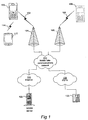
- Fig 1 illustrates one example of a telecommunications system in which the invention may be applied.
- various telecommunications services such as voice calls, data calls, facsimile transmissions, music transmissions, still image transmissions, video transmissions, electronic message transmissions and electronic commerce may be performed between a mobile terminal 100 according to the present invention and other devices, such as another mobile terminal 106, a PDA 112, a WWW server 122 and a stationary telephone 132.
- a mobile terminal 100 may or may not be available; the invention is not limited to any particular set of services in this respect.
- the mobile terminals 100, 106 are connected to a mobile telecommunications network 110 through RF links 102, 108 via base stations 104, 109.
- the mobile telecommunications network 110 may be in compliance with any commercially available mobile telecommunications standard, such as GSM, UMTS, D-AMPS or CDMA2000.
- the mobile telecommunications network 110 is operatively connected to a wide area network 120, which may be Internet or a part thereof.
- a wide area network 120 which may be Internet or a part thereof.
- client computers and server computers including WWW server 122, may be connected to the wide area network 120.
- PSTN 130 A public switched telephone network (PSTN) 130 is connected to the mobile telecommunications network 110 in a familiar manner.
- Various telephone terminals, including stationary telephone 132, are connected to the PSTN 130.
- a first embodiment 200 of the mobile terminal 100 is illustrated in slightly more detail in Fig 2a .
- the mobile terminal 200 comprises an apparatus housing 201, a loudspeaker 202, a display 203, a set of keys 204 which may include a keypad of common ITU-T type (alpha-numerical keypad), and a microphone 205.
- the mobile terminal 200 comprises various internal components, the more important of which are illustrated in Fig 4 and will be described later.
- External components 202-205 are all part of the user interface of the mobile terminal.
- the user interface involves a multi-way input device 210 in the form of a joystick, the handle of which may be actuated by the user in a plurality of directions 212/214 so as to command navigating operations, i.e. to navigate in corresponding directions among information 206 shown on display 203, in a manner which is conventional per se for joystick-equipped mobile terminals.
- the navigation directions may be 4 in number, as indicated by solid arrows 212 in Fig 2a , and may be distributed orthogonally in an "up, down, left, right” or “north, south, west, east” fashion with respect to a base plane which is essentially coincidental or parallel with the display 203 or the front surface of apparatus housing 201.
- the navigation directions may be 8 in number, as indicated by dashed lines 214 together with solid arrows 212 in Fig 2a , and may be distributed around a virtual circle in aforesaid base plane with successive 45° displacements, representing corresponding actuations of the joystick handle by the user.
- the user may also perform a selecting operation among information 206 by actuating the joystick 210 in a direction perpendicular to the base plane, e.g. by depressing the joystick at its top. Depending on implementation, this will either cause displacement of the entire joystick handle, or will cause depression of a joystick select button. In some embodiments such a joystick select button may be located at the top of the joystick handle; in others it may be mounted next to the joystick handle on the base plane.
- broader usage of the multi-way input device is made possible by linking or associating, in a given context, physical actions on the multi-way input device (e.g. joystick actuations in the various navigation and selection directions) with logical actions in the user interface (e.g. call handling operations, or issuing commands and performing confirmations in software applications, etc).
- logical actions in the user interface e.g. call handling operations, or issuing commands and performing confirmations in software applications, etc.
- the availability and meaning of such logical actions, selectable through associated physical actions on the multi-way input device are indicated to the user on the mobile terminal display.
- Fig 4 An example of this is found in Fig 4 , which moreover illustrates the mobile terminal's internal component and software structure.
- Fig 4 the availability and meaning of logical actions selectable through associated physical actions on a joystick 438 are indicated to the user by presenting information 490 on the display screen 480 of a display 436.
- the presented information 490 is dependent on context (situation), as represented by an information alert 482 on the display, and comprises explanatory text labels 494 which are shown grouped together in a spatial relationship on the display that reflects the corresponding spatial relationship between the associated physical actions on the joystick 438.
- the three logical actions that are associated with left, right and downward joystick actuation, respectively may be indicated as three text labels shown to the left of, right of and below a joystick icon 492 on the display. More examples and a deeper description of this inventive aspect will be given later with reference to the remaining drawings.
- the multi-way input device is implemented as a 5-way navigation key 210' which is can be actuated (depressed) at different circumferential positions 212', that represent different navigation directions 212', so as to generate navigating operations in similarity with the description above for the embodiment of Fig 2a .
- a selecting operation may be commanded by depressing the 5-way key 210' at is center 214'.
- the other components 201'-205' are preferably identical with or equivalent to components 201-205 of Fig 2a .
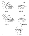
- Figs 3a and 3b illustrate a third embodiment 300 of the mobile terminal 100.
- this embodiment is foldable; the apparatus housing 301 is divided into two parts 301a and 301b which are pivotally interconnected at a hinge 301c.
- This arrangement allows use of the mobile terminal 300 in two different physical modes, an open mode as shown in Fig 3a and a closed mode as shown in Fig 3b , by turning the housing parts 301a-b to and from each other, as indicated by rotational arrow 301d.
- the open mode offers maximum usability to the user, since all major user interface components are conveniently accessible: a large display 303 located on the inside of one housing part 301b, and a speaker 302, a set of keys 304 and a microphone 305 located on the inside of the other housing part 301a.
- a multi-way input device 310 here in the form of a joystick, is available at one side of housing part 301a and provides the user with an ability to command navigating and selecting operations, just like in the previously described embodiments.
- the open mode is advantageously used in a variety of contexts, including conventional call handling as well as various software applications.
- the closed mode represents a compact physical shape which is particularly advantageous for idle periods, for instance when the terminal 300 is stored in a pocket, bag, etc.
- the large display 303 and set of keys 304 (seen in Fig 3a ) are protected from external influences and are also inaccessible to the user.
- a secondary, smaller display 313 is provided on the opposite side of housing part 301b, compared to the large primary display 303, and is therefore accessible for the user in the closed mode.
- the secondary display 313 may be used for presentation of idle or status information, such as date/time, battery level, RSSI, etc.
- the multi-way input device 310 which is accessible to the user also in the closed mode, some user interaction is possible even in the closed mode.
- Such user interaction may for instance include handling of incoming calls; by presenting a number of logical actions like "Answer”, “Reject” and “Silence” in a certain spatial relationship on secondary display 313 and mapping these to corresponding physical actions on the multi-way input device 310, the user may conveniently handle the incoming call without unfolding the terminal 300 in order to access the conventional call handling keys among the set of keys 304.
- a fourth embodiment 300' of the mobile terminal 100 is illustrated in Figs 3c and 3d .
- the fourth embodiment 300' resembles the third embodiment 300 of Figs 3a and 3b , except for the location of the multi-way input device 310'.
- the multi-way input device 310' implemented here as a joystick, is located on the inside of housing part 301a', between speaker 302' and set of keys 304'. Consequently, the multi-way input device 310' is accessible in the open mode but inaccessible in the closed mode.
- the fourth embodiment may be adapted for some user interaction also in the closed mode, Fig 3d , by way of the secondary display 313' and an external input device 340, which is provided on an accessory 330.
- a wireless handsfree unit 330 is connected to the mobile terminal 300' over a short-range wireless link 320.
- the link 320 is preferably established and maintained in accordance with any existing communication standard or protocol for short-range wireless data communication, including but not limited to any one of Bluetooth TM , WLAN, HomeRF and IrDA.
- the handsfree unit 330 is provided with a joystick 340 or another multi-way input device, and by actuating the joystick 340 in a desired direction 342, the user 350 may select and perform a logical action as presented on the secondary display 313'.
- the mobile terminal itself has no multi-way input device; such device is only provided on an accessory, like the joystick 340 on accessory 330 in Fig 3d .
- the availability of some other input means than a multi-way input device or a set of hard keys is indicated in the same or analogous way as has been described above, e.g. by presenting an explanatory text label for each logical action available through an associated physical action on such other input means.
- Voice activated control is one example of such other input means for which the inventive approach may be applied.
- the mobile terminal has a controller 400 which is responsible for the overall operation of the mobile terminal and is preferably implemented by any commercially available CPU ("Central Processing Unit"), DSP ("Digital Signal Processor") or any other electronic programmable logic device.
- the controller 400 has associated electronic memory 402 such as RAM memory, ROM memory, EEPROM memory, flash memory, or any combination thereof.
- the memory 402 is used for various purposes by the controller 400, one of them being for storing data and program instructions for various software in the mobile terminal.
- the software includes a real-time operating system 420, man-machine interface (MMI) drivers 434, an application handler 432 as well as various applications.
- the applications include a call handling application 450 as well as various other application 460-470, such as a contacts (phonebook) application, a messaging application, a calendar application, a control panel application, a camera application, a mediaplayer, one or more video games, a notepad application, etc.
- the MMI drivers 434 cooperate with the or each display 436, the joystick 438 as well as various other I/O devices such as a microphone, a speaker, a vibrator, a keypad, a ringtone generator, an LED indicator, volume controls, etc. As is commonly known, a user may operate the mobile terminal through the man-machine interface thus formed.
- the software also includes various modules, protocol stacks, drivers, etc., which are commonly designated as 430 and which provide communication services (such as transport, network and connectivity) for an RF interface 406, and optionally a Bluetooth interface 408 and/or an IrDA interface 410.
- the RF interface 406 comprises an internal or external antenna as well as appropriate radio circuitry for establishing and maintaining a wireless link to a base station (e.g. the link 102 and base station 104 in Fig 1 ).
- the radio circuitry comprises a series of analog and digital electronic components, together forming a radio receiver and transmitter. These components include, i.a., band pass filters, amplifiers, mixers, local oscillators, low pass filters, AD/DA converters, etc.
- the mobile terminal also has a SIM card 404 and an associated reader.
- the SIM card 404 comprises a processor as well as local work and data memory.
- the call handling application 450 handles all contexts in conventional voice call handling, e.g. receiving, announcing or rejecting incoming calls, and generating outgoing calls.
- the call handling application 450 may also keep record of various call statistics.
- this information 740 includes explanatory text labels 742 L , 742 R , 742 D which describe the logical actions “Answer”, “Reject” and “Silence” that are available for handling the incoming call through associated physical actions 752 L , 752 R , 752 D on the joystick 750.
- the text labels 742 L , 742 R , 742 D are grouped together in a spatial relationship on the display 700 that reflects the corresponding spatial relationship between the associated physical actions on the joystick 750; therefore the user is given the information that the call may be answered, rejected and silenced, respectively, by actuating the joystick 750 to the left, right and downwards, respectively.
- step 502 it is checked through CPU 400, real-time operating system 420, application handler 423 and MMI drivers 434 whether the joystick 438 has a defined functionality in the current context, e.g. the call handling application 450.
- a defined functionality may be embodied as predefined control data in the form of pieces of software code, i.e. program instructions and related control data, that are stored in memory 402 and are executable by CPU 400. If it is found in step 502 that the joystick has no defined functionality in the current context, the procedure is terminated in step 503.
- step 504 for the logical action(s) included in the defined functionality (e.g. the answering, rejection and silencing of an incoming call), information is presented on the display to indicate the associated physical action(s), and their spatial relationship if applicable, as well as to explain the logical action(s) (e.g. by way of the text labels "Answer” (742 L ), “Reject” (742 R ) and “Silence” (742 D ) of Fig 7a ).
- the logical action(s) included in the defined functionality e.g. the answering, rejection and silencing of an incoming call
- information is presented on the display to indicate the associated physical action(s), and their spatial relationship if applicable, as well as to explain the logical action(s) (e.g. by way of the text labels "Answer” (742 L ), "Reject” (742 R ) and “Silence” (742 D ) of Fig 7a ).
- step 506 physical actuation of the joystick 438 is detected by the MMI drivers 434 (e.g. an actuation of the joystick to the left (744 L )).
- Step 508 determines the logical action (e.g. call answering) with which the detected physical action is associated.
- the logical action is performed in step 510.
- performing a logical action relates to execution of a software function in the mobile terminal (e.g. invocation of a call answering subroutine in call handling application 450) upon selection by the joystick.
- performing this logical action will of course trigger performance of one or more other actions, in software as well as hardware (e.g. actions performed in modules 430 and 432, RF module 406 and in the mobile telecommunications network 110 to actually set up a call connection between the mobile terminal and the remote caller).
- the information 740 shown to indicate available joystick functionality preferably includes a symbolic graphic representation of the joystick, such as a small arrow 744 L (etc), indicating each direction 752 L (etc) in which the joystick 750 may be actuated to cause selection of a respective logical action described by an adjacent text label 742 L (etc).
- the information 740 may also include a center circle 744 C to represent "joystick-select", i.e. a displacement of the joystick handle or depression of the joystick select button depending on implementation.
- a joystick direction that has a defined functionality (i.e., is associated with a logical action) in the current context may be shown as a solid arrow, whereas a joystick direction that has no defined functionality in the current context may be omitted from presentation (such as joystick-up in Fig 7a ).
- directional arrows may be shown for all four joystick directions, whereas an "available" direction (joystick-left) is shown as a solid arrow (744 L ) and the "non-available" directions (joystick-right, joystick-up, joystick-down) are shown as empty arrows.
- solid directional arrows may be shown for all joystick directions, even the currently non-available ones.
- the available joystick directions will be indicated by the presence of their adjacent explanatory text labels; no explanatory text labels will be shown for non-available joystick directions.
- Fig 7a When there are more than one available joystick direction, as is the case in Fig 7a , the preferred or default logical action among these may be highlighted. Highlighting is achieved in Fig 7a by presenting the explanatory text label 742 L for the preferred or default logical action within a double-lined frame, whereas the other text labels have a single-lined frame. The user may select this highlighted option by simply performing a "joystick-select" 744 c (e.g. pressing a joystick select button) or by pushing the joystick handle to the left and maintaining it in this direction 744 L for a predetermined time ("joystick-long").
- a "joystick-select” 744 c e.g. pressing a joystick select button
- the latter case may be viewed upon as the joystick equivalent of a conventional "long press" on a hard key in a keypad (such as long-pressing "1" to reach the voicemail box).
- a conventional "long press” on a hard key in a keypad such as long-pressing "1" to reach the voicemail box.
- Such highlighting of preferred or default logical action is advantageous not only in that it provides guidance to a novice user as regards the most common or safe action in a given context; it moreover minimizes the physical activity required for selecting and performing a certain logical action. If in a given context the user does not want the highlighted action to be performed, he may select any one of the other options available by moving the joystick handle in the desired direction and then either doing a "joystick select" 744 C or a "joystick-long”.
- the Options action may present and propose different ways in which the user may configure his mobile terminal to better preserve electric power in the future. If the information message 722 announces that the mobile terminal has just reached the mobile telecommunications network of a foreign network operator (e.g. when passing a border between two countries), the Options action may present a list of selectable alternatives such as searching for other and perhaps more familiar operators or presenting detailed information about the new operator. Of course, these are just two among virtually unlimited numbers of Options actions in different contexts.
- Fig 7c presents an exemplifying context in a Camera application 460-470.
- the main presentation area 720 contains a flash settings window 722 with a list of selectable radio buttons.
- the information 740 about available joystick functionality includes solid arrows for all four joystick directions. However, explanatory text labels are shown for only two of these; "OK" for joystick-left and “Cancel” for joystick-right. No text labels are shown for the available joystick-up and joystick-down, since their meaning will be intuitive anyway given the current context: they are used for scrolling up and down in the list of radio buttons in flash settings window 722. Selecting one of the radio buttons may be done automatically once that radio button is scrolled to by joystick-up/joystick-down, or it may be done by a joystick-select (actuation of the joystick center position).
- FIG. 7d Another exemplifying context is presented in Fig 7d .
- a Mediaplayer application 460-470 is active.
- the main presentation area 720 contains a list 722 of music tunes on an available storage medium, and the currently playing tune 724 is shown surrounded by a frame.
- the lowermost area 730 of the display 700 contains local status information for the Mediaplayer application (in contrast to the status indication area 710 at the top which shows global status information).
- the local status information in area 730 includes a play time indicator 746 and a volume setting indicator 748.
- the area 730 includes information 740 about available joystick functionality in the visual form of an iconized representation of a joystick.
- the iconized joystick representation 740 includes four empty directional arrows 744 L , 744 R , 744 U , 744 D surrounding an iconized joystick center position 744 C . Since the directional arrows are shown as empty without any explanatory text label, they convey no information to the user about any available joystick directions; instead they are merely a part of the iconized joystick representation 740 which, as a whole, informs the user that the there is in fact some joystick functionality available in this context.
- this available joystick functionality is indicated by the iconized joystick center position 744 C .
- the iconized joystick center position 744 C represents a logical Pause action.
- a joystick-select in this context will pause the currently playing tune 724.
- the iconized joystick center position 744 C may change to another appearance, as shown in Fig 7f , and represent a logical Play action.
- performing a joystick-select in the context shown in Fig 7f will cause the tune 724 to start playing.
- the solid arrows 744 L , 744 R at either sides of the volume setting indicator 748 may in fact be included in the information 740 about available joystick functionality, even if they are shown separate from the iconized joystick representation at the lowermost left corner of the display 700.
- the solid arrows 744 L , 744 R will indicate and represent logical actions for lowering and increasing the current volume setting, respectively. They need no explanatory text labels, since their meaning is intuitive enough given their location next to the volume setting indicator 748. Even more intuitive is the meaning of joystick-up and joystick-down; these actions will scroll up and down in the list of 722 to change the currently playing tune 724. As appears from Fig 7e , these two available joystick actions are not at all indicated on the display 700.
- FIG. 8a-c An embodiment will now be described, with reference to Figs 8a-c , in which the joystick is used for invoking, launching or activating software applications starting from an idle screen.
- This embodiment is particularly advantageous when implemented in a mobile terminal of the type shown in Figs 3a-3d , i.e. having a primary display as well as a smaller secondary display, the latter of which is used predominantly in idle mode when the housing of the mobile terminal is put in a compact position.
- the joystick may be used in this idle mode to launch software applications from the secondary display 800 in Fig 8a .
- the secondary display 800 in the idle mode, basically displays nothing except for general status information in the status area 810.
- the background of the main presentation area 820 may be truly empty, as shown in Fig 8a , or may contain a background image or pattern. This far, the contents of the idle mode screen 800 resembles the ones known from the prior art.
- information 840 is shown at e.g. the lowermost left corner of the display 800 to indicate available joystick functionality.
- the information 840 has the form of a symbolic graphic representation of the joystick.
- the user is alerted of the fact that, in contrast to prior art idle screens, the idle mode may in fact be operated by way of the joystick. More particularly, by performing a joystick-select operation, the user will cause a switch from a first state for display 800 shown in Fig 8a to a second state shown in Fig 8b .
- the main presentation area is filled with a grid or matrix of icons for available software applications.
- a dice game icon 824a, a messaging application icon 824b and a help application icon 824c are shown in a first row on display 800
- a calculator icon 824d, a return-to-idle icon 824e and a money application icon 824f are shown in a second row on display 800
- a fax application icon 824g, a notes application icon 824h and a pacman game icon 824i are shown in a third row on display 800.
- eight software application icons 824abcd and 824fghi are centered around the return-to-idle icon 824e.
- a joystick-select If the user for some reason wants to return to the idle screen in Fig 8a , he simply performs a joystick-select. Otherwise, by actuating the joystick in a respective direction among 8 available directions (up, up-right, right, down-right, down, down-left, left, up-left), a respective application icon 824b, 824c, 824e, 824i, 824h, 824g, 824d and 824a may be selected.
- the selection of an icon may consist solely in pointing the joystick in the desired direction, or pointing in the desired direction followed by a highlighting of the desired icon and an affirmative joystick-select, or a combined operation of pointing in the desired direction and maintaining the actuation in that direction for a predetermined time (joystick-long).
- the software application associated with that icon will be invoked or launched, or activated if already executing in the background of the operating system, wherein that application will take command of the main presentation area 820 and fill it with application-specific contents.
- a return to the idle screen may have to be performed through other means than the return-to-idle icon 824e, such as through selection of a certain menu item (e.g. "Exit").
- Fig 8c illustrates an alternative to the embodiment described above.
- the main presentation area 820 upon joystick-select in the idle screen and the following switch from the first state to the second state, the main presentation area 820 will show an application grid with four, not eight, cells, each of which may contain an application icon 824b, 824d, 824f, 824h.
- an application icon 824b, 824d, 824f, 824h By actuating the joystick in different orthogonal directions (up, down, right, left), different ones of the application icons may be selected to invoke, launch or activate the associated application.
- a multi-way input device such as a joystick
- a joystick is used for invoking, launching or activating software applications starting from an idle screen.
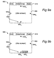
- this embodiment is particularly advantageous when implemented in a mobile terminal having a primary display as well as a smaller secondary display. It will now be described how the joystick may be used in idle mode to launch software applications from the secondary display 900 in Fig 9a .
- the secondary display 900 displays the general status information in the status area 910.
- the main presentation area 920 contains nothing except for information 940 which indicates available joystick functionality.
- the information 940 is divided into four arrows 944 L , 944 R , 944 U , 944 D which are distributed to four different remote positions on the display 900.
- the arrows 944 L , 944 R , 944 U , 944 D represent the four joystick directions. Their presence on the display 900 alerts the user of the fact that, in contrast to prior art idle screens, the idle mode may in fact be operated by way of the joystick so as to launch, invoke or activate software applications. More particularly, each arrow is associated with a respective software application. In contrast to the previous embodiment, no application icons are shown. By actuating the joystick in a certain direction, the user will cause launch/invocation/activation of the associated software application.
- Explanatory text labels may be shown next to the arrows 944 L , 944 R , 944 U , 944 D to increase the clarity for the user as regards which applications that are associated with the joystick directions.
- a trade-off between keeping a clean idle screen and giving some guidance to the user is shown in Fig 9b .
- an explanatory text label 942 D is shown only once that joystick direction (joystick-down) has been actuated.
- the user may explore the meaning of the different arrows by actuating the joystick in different directions.
- a selected application may be affirmed by a joystick-select or a joystick-long, as has already been explained above for other embodiments.
- the different embodiments described above of how the information about available joystick functionality may be shown in different contexts are just examples. Many other combinations of and alternatives to the ways described above are possible within the spirit of the invention.
- a four-way/five-way navigation key may be used instead of a joystick as multi-way input device in any of the embodiments described above.
- the multi-way input device may be a touch-sensitive display screen which is operated by pointing, clicking or tapping with a pen, stylus or finger, etc.
Abstract
Description
- The present invention relates to mobile telecommunication and more particularly to improvements in the user interface of a mobile terminal that has a multi-way input device such as a joystick.
- A mobile (cellular) telephone for a telecommunications system like GSM, UMTS, D-AMPS or CDMA2000 is a common example of a mobile terminal according to the above. For many years, the conventional user interface of mobile telephones were limited to a display, a keypad, a speaker and a microphone. As regards the keypad, it normally included an alpha-numeric or ITU-T type set of keys (characters "0"-"9", "*", "#", and a few other keys such as call handling keys for "Call"/"Yes" and "Hangup"/"No". In such conventional mobile terminals, essentially all non-acoustic user input was entered through the keypad (expect for certain specific control operations that were done through dedicated buttons, such and volume control buttons).
- A keypad as described above has its limitations as regards user-friendliness. In older days, when a mobile terminal was used almost only for speech communication, an ITU-T type keypad sufficed for most users, since the required user interaction was essentially limited to the dialing of telephone numbers and call handling for generating outgoing calls and answering or rejecting incoming calls. Modern terminals, on the other hand, are used for many other purposes than merely speech communication; electronic messaging, recording of digital pictures or video, listening to FM radio or MP3 music, and electronic games being just a few examples of software applications that are typically used in a contemporary mobile terminal. For such applications, an ITU-T type keypad is clearly insufficient if used as the only input device in the mobile terminal.
- One popular way in the prior art to extend the usability of the user interface in a mobile terminal having an ITU-T type keypad has been to introduce soft keys into the user interface.
Fig 6 gives a schematic illustration of a prior art mobile terminal having a user interface which includes adisplay 600 and an ITU-T type keypad 640. The latter includes conventional alpha-numerichard keys 646 as well as left and rightsoft keys hard keys 646 are not harder than the soft keys in a physical sense but normally only has one meaning irrespective of application, e.g. the hard key labeled "1" represents the digit "1" both in call handling and a calendar application as well as in a calculator application. - In the exemplifying situation given in
Fig 6 , astatus area 610 at the uppermost part of thedisplay 600 presents general information that is not associated with a particular application, such as date/time, battery level and RSSI (Received Signal Strength Indicator). An incoming call is announced as amessage 622 in amain presentation area 620. Alowermost area 630 of thedisplay 600 showsrespective text labels soft keys soft key labels text labels - An ITU-T type keypad is not particularly advantageous for navigation and selection among information presented on the display. Since this is frequently required in the various applications available in a modern mobile terminal, it is known in the prior art to provide a mobile terminal with other kinds of input devices instead of or in addition to an ITU-T type keypad, such as a multi-way input device in the form of a joystick or 4-way/5-way navigation key. Such a multi-way input device is advantageous for two reasons: it is physically compact and therefore conforms well to modern demands for miniaturization, and it represents an intuitive and easily operated means for navigating and selecting among information presented on the mobile terminal's display. For instance, the Nokia® 7650 has, in addition to a retractable ITU-T keypad, a joystick placed between two soft keys. The joystick is used as a means for scrolling in lists and among user interface objects such as icons and menu items.
- In recent years, some mobile terminal models have been introduced that have two displays. A primary, larger display is predominantly used for all user interaction in active operating modes, whereas a secondary, smaller display is used for certain indication of basic status information in idle mode. In some models, the primary display is a high-resolution color display, whereas the secondary display is an inexpensive monochrome display. This arrangement is typically used for a foldable or otherwise closable two-part mobile terminal having an open position where the primary display is available, and a closed position where only the secondary display is available. Hence, the primary display is used for all user interaction, including user input by way of an ITU-T keypad and/or a multi-way input device, whereas the secondary display is used for limited presentational purposes but not for user input. The primary display is sometimes of touch-sensitive type, which may be operated by way of a pen or stylus in a PDA (Portable/Personal Digital Assistant) manner.
-
EP1359495 discloses functions in a menu layer structure comprising a top menu layer and at least one lower menu layer wherein one of said at least one lower menu layer being as a bottom menu layer. The top menu layer is at least partly overlapping said lower menu layers. The user selects a menu layer to be provided as a top menu layer from said at least one lower menu layer by giving a first command, and selects a function to be performed from said top menu layer by giving a second command. -
EP1179944 discloses a portable telephone having a display that displays a block indicative of an operator, predetermined information and a pointer. The operator can be operated in directions opposite to each other; and the controller controls the display so as to shift the pointer to a desirable position within predetermined information on a screen of the display in accordance with an operation of the operator and also displays a mark indicative of a direction to which the pointer can be shifted. -
EP 1004957 discloses a portable terminal comprising a LCD display screen located on a control surface of a case for displaying thereon information according to the communication mode; a main soft key located below the LCD display screen with which can be rotated in a direction towards or away from the display screen as well as can be pressed; and a first auxiliary soft key located on the two sides of the main soft key which can be pressed. -
US20040189597 discloses a wireless portable terminal comprising a first case and a second case which are interconnected by a hinge mechanism. The second case is closable to a first posture wherein a front surface of the first case is covered, and is openable to a second posture wherein the surface is exposed. - In view of the above, an objective of the invention is to solve or at least reduce the problems discussed above. In more particular, the present invention seeks to provide improvements to the user interface of a mobile terminal having a multi-way input device by extending the utilization of the multi-way input device to functions and situations not hitherto associated with such a device. Thus, one object is to facilitate use of the multi-way input device as a control means also for other actions than traditional navigation in the user interface. Another object is to allow the secondary display of a mobile terminal, which also has a primary display, to be used for more than just certain indication of basic status information in idle mode.
- Generally, the above objectives are achieved by the attached independent patent claims.
- A first aspect of the invention is a mobile terminal having a user interface formed by a controller, a display and a multi-way input device for navigating and selecting among information shown on said display, the mobile terminal comprising a plurality of software applications executable by said controller,
said user interface having a first state, in which a graphical indication of said multi-way input device is presented on said display, and a second state, in which graphical indications for at least some of said plurality of software applications are presented on said display;
said controller being adapted, in said first state, to detect a first predefined actuation of said multi-way input device, and in response switch to said second state;
said controller being adapted, in said second state, to provide for navigation and selection, by said multi-way input device, among the graphical indications presented for said at least some of said plurality of software applications, wherein a selection of one of said presented graphical indications activates an associated one of said at least some of said plurality of software applications. - As used herein, to "activate a software application" includes but is not limited to the following alternatives: launching an application under the control or supervision of the controller and/or the operating system in the mobile terminal; invoking an application by making a subroutine call from a current execution point such as a dedicated idle application, or an idle routine executed by the controller and/or the operating system, to the application to be activated; or activating the application by having the controller and/or the operating system transferring its state from a current background process status to a foreground process status.
- In one embodiment, the mobile terminal has a primary display and a secondary display, the primary display being adapted for use in an active operating mode and/or in an open apparatus housing configuration, and the secondary display being adapted for use in an idle operating mode and/or in a closed apparatus housing configuration, wherein said first and second states of said user interface pertain to the secondary display and/or the idle operating mode.
- In said second state, a graphical indication of said multi-way input device may be presented on said display in addition to said graphical indications presented for said at least some of said plurality of software applications. The graphical indications presented for said at least some of said plurality of software applications may be arranged in a two-dimensional matrix or grid, wherein said graphical indication of said multi-way input device is positioned at the center of the matrix or grid.
- The controller may be adapted, in said second state, to detect a second predefined actuation of said multi-way input device, and in response switch to said first state. Both said first and said second predefined actuation of said multi-way input device may be a select operation.
- The multi-way input device advantageously includes a joystick or a four-way/five-way navigation key. The mobile terminal may be a mobile phone adapted for use in a mobile telecommunications network.
- A second aspect of the invention is a method of operating a user interface of a mobile terminal having a display and a multi-way input device for navigating and selecting among information shown on said display, the mobile terminal comprising a plurality of software applications, the method involving the steps of:
- presenting on said display a plurality of graphical indications, each indication representing a respective one of at least some of said plurality of software applications;
- detecting a selection by said multi-way input device of one of said indications; and
- activating an associated software application which is represented by the selected indication.
- "Activating a [...] software application" has the same meaning as explained above for the fourth aspect.
- Said plurality of graphical indications may be distributed to different and mutually remote positions on a display area of the display. Each of said plurality of graphical indications may be a small graphical arrow that serves to indicate a respective navigation direction on said multi-way input device.
- The method may involve the additional step of presenting a text label describing the associated software application adjacent to a respective one of said plurality of graphical indications. Said step of presenting a text label may be performed once the respective one of said plurality of graphical indications has been navigated to by said multi-way input device.
- For a mobile terminal having a primary display and a secondary display, the steps of the method may be performed in an idle state of said mobile terminal, using said secondary display but not said primary display.
- The multi-way input device may include a joystick or a four-way/five-way navigation key. In one embodiment, the multi-way input device and the display are part of a touch-sensitive display screen.
- The mobile terminal may be a mobile phone adapted for use in a mobile telecommunications network.
- Other objectives, features and advantages of the present invention will appear from the following detailed disclosure, from the attached dependent claims as well as from the drawings.
- Generally, all terms used in the claims are to be interpreted according to their ordinary meaning in the technical field, unless explicitly defined otherwise herein. All references to "a/an/the [element, device, component, means, step, etc]" are to be interpreted openly as referring to at least one instance of said element, device, component, means, step, etc., unless explicitly stated otherwise. The steps of any method disclosed herein do not have to be performed in the exact order disclosed, unless explicitly stated.
- Embodiments of the present invention will now be described in more detail, reference being made to the enclosed drawings, in which:
-
Fig 1 is a schematic illustration of a telecommunication system, including a mobile terminal, a mobile telecommunications network and a couple of other devices, as an example of an environment in which the present invention may be applied. -
Fig 2a is a schematic front view illustrating a mobile terminal according to a first embodiment, and in particular some external components that are part of a user interface towards a user of the mobile terminal. -
Fig 2b is a schematic front view illustrating a mobile terminal according to a second embodiment. -
Figs 3a and 3b are schematic perspective views illustrating a mobile terminal according to a third embodiment. -
Figs 3c and 3d are schematic perspective views illustrating a mobile terminal according to a fourth embodiment. -
Fig 4 is a schematic block diagram representing the internal component and software structure of a mobile terminal, which may be any one of the embodiments shown inFigs 2a-2b , 3a-3b or 3c-3d. -
Fig 5 is a flowchart diagram that illustrates the operation of one embodiment to indicate the availability of certain joystick functionality in a given context, to detect selection of the functionality by actuation of the joystick, and to perform the functionality. -
Fig 6 is a schematic illustration of the user interface of a mobile terminal of the prior art in the context of handling an incoming call, the user interface including an ITU-T type keypad with soft keys for which text labels are presented on the display. -
Fig 7 is a schematic illustration of the user interface of a mobile terminal according to one embodiment in the same context as inFig 6 , the user interface including a joystick, different logical actions for call handling being associated with different physical actions on the joystick, and information being presented on the display to indicate the availability of each of these logical actions. -
Fig 7a is an enlarged schematic view of the information presented on the display inFig 7 to indicate the availability of the logical actions through associated physical actions on the joystick. -
Figs 7b-7d are different schematic display snapshots, from different contexts, which give further examples of how information may be presented on the display to indicate the availability of logical actions through associated physical actions on the joystick. -
Fig 7e is an enlarged schematic view of the information presented on the display inFig 7d , -
Fig 7f is an enlarged schematic view of information that alternatively may be presented for the same context as inFig 7e . -
Figs 8a-c illustrate an embodiment which supports easy software application invocation/launch/activation by way of a multi-input device starting from an idle screen of a mobile terminal. -
Figs 9a-b illustrate another embodiment which supports easy software application invocation/launch/- activation by way of a multi-input device starting from an idle screen of a mobile terminal. -
Fig 1 illustrates one example of a telecommunications system in which the invention may be applied. In the telecommunication system ofFig 1 , various telecommunications services such as voice calls, data calls, facsimile transmissions, music transmissions, still image transmissions, video transmissions, electronic message transmissions and electronic commerce may be performed between amobile terminal 100 according to the present invention and other devices, such as anothermobile terminal 106, aPDA 112, aWWW server 122 and astationary telephone 132. It is to be noticed that for different embodiments of themobile terminal 100, different ones of the telecommunications services referred to above may or may not be available; the invention is not limited to any particular set of services in this respect. - The
mobile terminals mobile telecommunications network 110 throughRF links base stations mobile telecommunications network 110 may be in compliance with any commercially available mobile telecommunications standard, such as GSM, UMTS, D-AMPS or CDMA2000. - The
mobile telecommunications network 110 is operatively connected to awide area network 120, which may be Internet or a part thereof. Various client computers and server computers, includingWWW server 122, may be connected to thewide area network 120. - A public switched telephone network (PSTN) 130 is connected to the
mobile telecommunications network 110 in a familiar manner. Various telephone terminals, includingstationary telephone 132, are connected to thePSTN 130. - A
first embodiment 200 of themobile terminal 100 is illustrated in slightly more detail inFig 2a . As is well known in the art, themobile terminal 200 comprises anapparatus housing 201, aloudspeaker 202, adisplay 203, a set ofkeys 204 which may include a keypad of common ITU-T type (alpha-numerical keypad), and amicrophone 205. In addition, but not shown inFig 2a , themobile terminal 200 comprises various internal components, the more important of which are illustrated inFig 4 and will be described later. External components 202-205 are all part of the user interface of the mobile terminal. - Furthermore, the user interface involves a
multi-way input device 210 in the form of a joystick, the handle of which may be actuated by the user in a plurality ofdirections 212/214 so as to command navigating operations, i.e. to navigate in corresponding directions amonginformation 206 shown ondisplay 203, in a manner which is conventional per se for joystick-equipped mobile terminals. The navigation directions may be 4 in number, as indicated bysolid arrows 212 inFig 2a , and may be distributed orthogonally in an "up, down, left, right" or "north, south, west, east" fashion with respect to a base plane which is essentially coincidental or parallel with thedisplay 203 or the front surface ofapparatus housing 201. Alternatively, the navigation directions may be 8 in number, as indicated by dashedlines 214 together withsolid arrows 212 inFig 2a , and may be distributed around a virtual circle in aforesaid base plane with successive 45° displacements, representing corresponding actuations of the joystick handle by the user. - The user may also perform a selecting operation among
information 206 by actuating thejoystick 210 in a direction perpendicular to the base plane, e.g. by depressing the joystick at its top. Depending on implementation, this will either cause displacement of the entire joystick handle, or will cause depression of a joystick select button. In some embodiments such a joystick select button may be located at the top of the joystick handle; in others it may be mounted next to the joystick handle on the base plane. - In accordance with the invention, broader usage of the multi-way input device than in the prior art is made possible by linking or associating, in a given context, physical actions on the multi-way input device (e.g. joystick actuations in the various navigation and selection directions) with logical actions in the user interface (e.g. call handling operations, or issuing commands and performing confirmations in software applications, etc). To the benefit of the user, the availability and meaning of such logical actions, selectable through associated physical actions on the multi-way input device, are indicated to the user on the mobile terminal display. An example of this is found in
Fig 4 , which moreover illustrates the mobile terminal's internal component and software structure. - In
Fig 4 , the availability and meaning of logical actions selectable through associated physical actions on ajoystick 438 are indicated to the user by presentinginformation 490 on thedisplay screen 480 of adisplay 436. The presentedinformation 490 is dependent on context (situation), as represented by aninformation alert 482 on the display, and comprises explanatory text labels 494 which are shown grouped together in a spatial relationship on the display that reflects the corresponding spatial relationship between the associated physical actions on thejoystick 438. For instance, the three logical actions that are associated with left, right and downward joystick actuation, respectively, may be indicated as three text labels shown to the left of, right of and below ajoystick icon 492 on the display. More examples and a deeper description of this inventive aspect will be given later with reference to the remaining drawings. - Referring now to
Fig 2b , a second embodiment 200' of themobile terminal 100 is illustrated. In this embodiment, the multi-way input device is implemented as a 5-way navigation key 210' which is can be actuated (depressed) at different circumferential positions 212', that represent different navigation directions 212', so as to generate navigating operations in similarity with the description above for the embodiment ofFig 2a . Furthermore, a selecting operation may be commanded by depressing the 5-way key 210' at is center 214'. The other components 201'-205' are preferably identical with or equivalent to components 201-205 ofFig 2a . -
Figs 3a and 3b illustrate athird embodiment 300 of themobile terminal 100. In contrast to the embodiments described above, this embodiment is foldable; theapparatus housing 301 is divided into twoparts hinge 301c. This arrangement allows use of themobile terminal 300 in two different physical modes, an open mode as shown inFig 3a and a closed mode as shown inFig 3b , by turning thehousing parts 301a-b to and from each other, as indicated byrotational arrow 301d. - The open mode,
Fig 3a , offers maximum usability to the user, since all major user interface components are conveniently accessible: alarge display 303 located on the inside of onehousing part 301b, and aspeaker 302, a set ofkeys 304 and amicrophone 305 located on the inside of theother housing part 301a. In addition, amulti-way input device 310, here in the form of a joystick, is available at one side ofhousing part 301a and provides the user with an ability to command navigating and selecting operations, just like in the previously described embodiments. The open mode is advantageously used in a variety of contexts, including conventional call handling as well as various software applications. - The closed mode, on the other hand, represents a compact physical shape which is particularly advantageous for idle periods, for instance when the terminal 300 is stored in a pocket, bag, etc. In the closed mode, as seen in
Fig 3b , thelarge display 303 and set of keys 304 (seen inFig 3a ) are protected from external influences and are also inaccessible to the user. However, a secondary,smaller display 313 is provided on the opposite side ofhousing part 301b, compared to the largeprimary display 303, and is therefore accessible for the user in the closed mode. Thesecondary display 313 may be used for presentation of idle or status information, such as date/time, battery level, RSSI, etc. In addition, thanks to the provision of themulti-way input device 310, which is accessible to the user also in the closed mode, some user interaction is possible even in the closed mode. Such user interaction may for instance include handling of incoming calls; by presenting a number of logical actions like "Answer", "Reject" and "Silence" in a certain spatial relationship onsecondary display 313 and mapping these to corresponding physical actions on themulti-way input device 310, the user may conveniently handle the incoming call without unfolding the terminal 300 in order to access the conventional call handling keys among the set ofkeys 304. Again, more examples and a deeper description of this inventive aspect will be given later with reference to the remaining drawings. - A fourth embodiment 300' of the
mobile terminal 100 is illustrated inFigs 3c and 3d . The fourth embodiment 300' resembles thethird embodiment 300 ofFigs 3a and 3b , except for the location of the multi-way input device 310'. The multi-way input device 310', implemented here as a joystick, is located on the inside ofhousing part 301a', between speaker 302' and set of keys 304'. Consequently, the multi-way input device 310' is accessible in the open mode but inaccessible in the closed mode. Nevertheless, the fourth embodiment may be adapted for some user interaction also in the closed mode,Fig 3d , by way of the secondary display 313' and anexternal input device 340, which is provided on anaccessory 330. As seen inFig 3d , a wirelesshandsfree unit 330 is connected to the mobile terminal 300' over a short-range wireless link 320. Thelink 320 is preferably established and maintained in accordance with any existing communication standard or protocol for short-range wireless data communication, including but not limited to any one of Bluetooth™, WLAN, HomeRF and IrDA. Thehandsfree unit 330 is provided with ajoystick 340 or another multi-way input device, and by actuating thejoystick 340 in a desireddirection 342, theuser 350 may select and perform a logical action as presented on the secondary display 313'. - In an alternative to the embodiments disclosed above, the mobile terminal itself has no multi-way input device; such device is only provided on an accessory, like the
joystick 340 onaccessory 330 inFig 3d . In another alternative, the availability of some other input means than a multi-way input device or a set of hard keys is indicated in the same or analogous way as has been described above, e.g. by presenting an explanatory text label for each logical action available through an associated physical action on such other input means. Voice activated control (VAC) is one example of such other input means for which the inventive approach may be applied. - The internal component and software structure of a mobile terminal according to one embodiment, which may be any of the afore-mentioned embodiments, will now be described with reference to
Fig 4 . The mobile terminal has acontroller 400 which is responsible for the overall operation of the mobile terminal and is preferably implemented by any commercially available CPU ("Central Processing Unit"), DSP ("Digital Signal Processor") or any other electronic programmable logic device. Thecontroller 400 has associatedelectronic memory 402 such as RAM memory, ROM memory, EEPROM memory, flash memory, or any combination thereof. Thememory 402 is used for various purposes by thecontroller 400, one of them being for storing data and program instructions for various software in the mobile terminal. The software includes a real-time operating system 420, man-machine interface (MMI)drivers 434, anapplication handler 432 as well as various applications. The applications include acall handling application 450 as well as various other application 460-470, such as a contacts (phonebook) application, a messaging application, a calendar application, a control panel application, a camera application, a mediaplayer, one or more video games, a notepad application, etc. - The
MMI drivers 434 cooperate with the or eachdisplay 436, thejoystick 438 as well as various other I/O devices such as a microphone, a speaker, a vibrator, a keypad, a ringtone generator, an LED indicator, volume controls, etc. As is commonly known, a user may operate the mobile terminal through the man-machine interface thus formed. - The software also includes various modules, protocol stacks, drivers, etc., which are commonly designated as 430 and which provide communication services (such as transport, network and connectivity) for an
RF interface 406, and optionally aBluetooth interface 408 and/or anIrDA interface 410. TheRF interface 406 comprises an internal or external antenna as well as appropriate radio circuitry for establishing and maintaining a wireless link to a base station (e.g. thelink 102 andbase station 104 inFig 1 ). As is well known to a man skilled in the art, the radio circuitry comprises a series of analog and digital electronic components, together forming a radio receiver and transmitter. These components include, i.a., band pass filters, amplifiers, mixers, local oscillators, low pass filters, AD/DA converters, etc. - The mobile terminal also has a
SIM card 404 and an associated reader. As is commonly known, theSIM card 404 comprises a processor as well as local work and data memory. - The
call handling application 450 handles all contexts in conventional voice call handling, e.g. receiving, announcing or rejecting incoming calls, and generating outgoing calls. Thecall handling application 450 may also keep record of various call statistics. -
Fig 5 is a flowchart diagram that illustrates the operation of one embodiment to indicate the availability of certain joystick functionality in a given context, to detect selection of the functionality by actuation of the joystick, and to perform the functionality. The steps of the method shown inFig 5 will be explained below with reference to one exemplifying context, which is shown inFig 7 and which pertains to the handling of an incoming telephone call. - Thus, referring briefly to
Fig 7 before turning toFig 5 , it is seen that astatus area 710 is provided at the uppermost part of thedisplay 700. Thestatus area 710 presents general information that is not associated with a particular application, such as date/time, battery level and RSSI. An incoming call is announced as a pop-upmessage 722 in amain presentation area 720. This far, the display screen ofFig 7 resembles the one according to the prior art shown in afore-describedFig 6 . In contrast to the prior art, however, available logical actions for call handling are not shown in a lowermost area of the display as text labels associated with soft keys (cf.reference numerals Fig 6 ). Instead, the logical actions available are shown asinformation 740 next to thecall announcement message 722. In more particular, as seen also inFig 7a , thisinformation 740 includes explanatory text labels 742L, 742R, 742D which describe the logical actions "Answer", "Reject" and "Silence" that are available for handling the incoming call through associatedphysical actions joystick 750. The text labels 742L, 742R, 742D are grouped together in a spatial relationship on thedisplay 700 that reflects the corresponding spatial relationship between the associated physical actions on thejoystick 750; therefore the user is given the information that the call may be answered, rejected and silenced, respectively, by actuating thejoystick 750 to the left, right and downwards, respectively. - Thus, with reference again to
Fig 5 as well as toFig 4 , for a givencontext 500, which may be the call handling situation shown inFig 7 , the following steps are performed. Instep 502, it is checked throughCPU 400, real-time operating system 420, application handler 423 andMMI drivers 434 whether thejoystick 438 has a defined functionality in the current context, e.g. thecall handling application 450. As is appreciated by those skilled in the art, such defined functionality may be embodied as predefined control data in the form of pieces of software code, i.e. program instructions and related control data, that are stored inmemory 402 and are executable byCPU 400. If it is found instep 502 that the joystick has no defined functionality in the current context, the procedure is terminated instep 503. Otherwise, instep 504, for the logical action(s) included in the defined functionality (e.g. the answering, rejection and silencing of an incoming call), information is presented on the display to indicate the associated physical action(s), and their spatial relationship if applicable, as well as to explain the logical action(s) (e.g. by way of the text labels "Answer" (742L), "Reject" (742R) and "Silence" (742D) ofFig 7a ). - In
step 506, physical actuation of thejoystick 438 is detected by the MMI drivers 434 (e.g. an actuation of the joystick to the left (744L)). Step 508 determines the logical action (e.g. call answering) with which the detected physical action is associated. The logical action is performed instep 510. As used herein, performing a logical action relates to execution of a software function in the mobile terminal (e.g. invocation of a call answering subroutine in call handling application 450) upon selection by the joystick. In turn, performing this logical action will of course trigger performance of one or more other actions, in software as well as hardware (e.g. actions performed inmodules RF module 406 and in themobile telecommunications network 110 to actually set up a call connection between the mobile terminal and the remote caller). - The
information 740 shown to indicate available joystick functionality preferably includes a symbolic graphic representation of the joystick, such as a small arrow 744L (etc), indicating each direction 752L (etc) in which thejoystick 750 may be actuated to cause selection of a respective logical action described by an adjacent text label 742L (etc). Theinformation 740 may also include acenter circle 744C to represent "joystick-select", i.e. a displacement of the joystick handle or depression of the joystick select button depending on implementation. - As seen in
Fig 7a , a joystick direction that has a defined functionality (i.e., is associated with a logical action) in the current context may be shown as a solid arrow, whereas a joystick direction that has no defined functionality in the current context may be omitted from presentation (such as joystick-up inFig 7a ). Alternatively, as seen inFig 7b , directional arrows may be shown for all four joystick directions, whereas an "available" direction (joystick-left) is shown as a solid arrow (744L) and the "non-available" directions (joystick-right, joystick-up, joystick-down) are shown as empty arrows. As a further alternative, solid directional arrows may be shown for all joystick directions, even the currently non-available ones. In such an alternative, the available joystick directions will be indicated by the presence of their adjacent explanatory text labels; no explanatory text labels will be shown for non-available joystick directions. - When there are more than one available joystick direction, as is the case in
Fig 7a , the preferred or default logical action among these may be highlighted. Highlighting is achieved inFig 7a by presenting theexplanatory text label 742L for the preferred or default logical action within a double-lined frame, whereas the other text labels have a single-lined frame. The user may select this highlighted option by simply performing a "joystick-select" 744c (e.g. pressing a joystick select button) or by pushing the joystick handle to the left and maintaining it in thisdirection 744L for a predetermined time ("joystick-long"). The latter case may be viewed upon as the joystick equivalent of a conventional "long press" on a hard key in a keypad (such as long-pressing "1" to reach the voicemail box). Such highlighting of preferred or default logical action is advantageous not only in that it provides guidance to a novice user as regards the most common or safe action in a given context; it moreover minimizes the physical activity required for selecting and performing a certain logical action. If in a given context the user does not want the highlighted action to be performed, he may select any one of the other options available by moving the joystick handle in the desired direction and then either doing a "joystick select" 744C or a "joystick-long". - It is possible to assign a logical action to the joystick
select position 744C, rather than merely serving to select logical actions represented by thejoystick directions Fig 7b , the joystickselect position 744C is given a iconized appearance, rather than a simple empty circle, and represents an Options action. Thus, upon "joystick-select", instead of executing theClose action 742L, options available for further handling of the current context (as described by the information message 722) will be presented on thedisplay 700. For instance, if theinformation message 722 alerts about an upcoming shortage of battery charge, the Options action may present and propose different ways in which the user may configure his mobile terminal to better preserve electric power in the future. If theinformation message 722 announces that the mobile terminal has just reached the mobile telecommunications network of a foreign network operator (e.g. when passing a border between two countries), the Options action may present a list of selectable alternatives such as searching for other and perhaps more familiar operators or presenting detailed information about the new operator. Of course, these are just two among virtually unlimited numbers of Options actions in different contexts. -
Fig 7c presents an exemplifying context in a Camera application 460-470. Here, themain presentation area 720 contains aflash settings window 722 with a list of selectable radio buttons. Theinformation 740 about available joystick functionality includes solid arrows for all four joystick directions. However, explanatory text labels are shown for only two of these; "OK" for joystick-left and "Cancel" for joystick-right. No text labels are shown for the available joystick-up and joystick-down, since their meaning will be intuitive anyway given the current context: they are used for scrolling up and down in the list of radio buttons inflash settings window 722. Selecting one of the radio buttons may be done automatically once that radio button is scrolled to by joystick-up/joystick-down, or it may be done by a joystick-select (actuation of the joystick center position). - Another exemplifying context is presented in
Fig 7d . Here, a Mediaplayer application 460-470 is active. Themain presentation area 720 contains alist 722 of music tunes on an available storage medium, and the currently playingtune 724 is shown surrounded by a frame. Thelowermost area 730 of thedisplay 700 contains local status information for the Mediaplayer application (in contrast to thestatus indication area 710 at the top which shows global status information). The local status information inarea 730 includes aplay time indicator 746 and avolume setting indicator 748. Moreover, thearea 730 includesinformation 740 about available joystick functionality in the visual form of an iconized representation of a joystick. As seen more clearly inFig 7e , the iconizedjoystick representation 740 includes four emptydirectional arrows joystick center position 744C. Since the directional arrows are shown as empty without any explanatory text label, they convey no information to the user about any available joystick directions; instead they are merely a part of the iconizedjoystick representation 740 which, as a whole, informs the user that the there is in fact some joystick functionality available in this context. - In more particular, this available joystick functionality is indicated by the iconized
joystick center position 744C. InFig 7e , the iconizedjoystick center position 744C represents a logical Pause action. In other words, a joystick-select in this context will pause the currently playingtune 724. Once the tune has been paused, the iconizedjoystick center position 744C may change to another appearance, as shown inFig 7f , and represent a logical Play action. Hence, performing a joystick-select in the context shown inFig 7f will cause thetune 724 to start playing. - Optionally, as indicated in
Fig 7e , thesolid arrows volume setting indicator 748 may in fact be included in theinformation 740 about available joystick functionality, even if they are shown separate from the iconized joystick representation at the lowermost left corner of thedisplay 700. In other words, thesolid arrows volume setting indicator 748. Even more intuitive is the meaning of joystick-up and joystick-down; these actions will scroll up and down in the list of 722 to change the currently playingtune 724. As appears fromFig 7e , these two available joystick actions are not at all indicated on thedisplay 700. - An embodiment will now be described, with reference to
Figs 8a-c , in which the joystick is used for invoking, launching or activating software applications starting from an idle screen. This embodiment is particularly advantageous when implemented in a mobile terminal of the type shown inFigs 3a-3d , i.e. having a primary display as well as a smaller secondary display, the latter of which is used predominantly in idle mode when the housing of the mobile terminal is put in a compact position. In more particular, it will now be described how the joystick may be used in this idle mode to launch software applications from thesecondary display 800 inFig 8a . - As seen in
Fig 8a , in the idle mode, thesecondary display 800 basically displays nothing except for general status information in thestatus area 810. The background of themain presentation area 820 may be truly empty, as shown inFig 8a , or may contain a background image or pattern. This far, the contents of theidle mode screen 800 resembles the ones known from the prior art. In addition, however,information 840 is shown at e.g. the lowermost left corner of thedisplay 800 to indicate available joystick functionality. InFig 8a , theinformation 840 has the form of a symbolic graphic representation of the joystick. By presenting thisinformation 840, the user is alerted of the fact that, in contrast to prior art idle screens, the idle mode may in fact be operated by way of the joystick. More particularly, by performing a joystick-select operation, the user will cause a switch from a first state fordisplay 800 shown inFig 8a to a second state shown inFig 8b . - When this switching of states occurs, the main presentation area is filled with a grid or matrix of icons for available software applications. In the example shown in
Fig 8b , adice game icon 824a, amessaging application icon 824b and ahelp application icon 824c are shown in a first row ondisplay 800, acalculator icon 824d, a return-to-idle icon 824e and amoney application icon 824f are shown in a second row ondisplay 800, and afax application icon 824g, anotes application icon 824h and apacman game icon 824i are shown in a third row ondisplay 800. Thus, eight software application icons 824abcd and 824fghi are centered around the return-to-idle icon 824e. If the user for some reason wants to return to the idle screen inFig 8a , he simply performs a joystick-select. Otherwise, by actuating the joystick in a respective direction among 8 available directions (up, up-right, right, down-right, down, down-left, left, up-left), arespective application icon main presentation area 820 and fill it with application-specific contents. Since the joystick will likely be used for other purposes in the thus active application, a return to the idle screen may have to be performed through other means than the return-to-idle icon 824e, such as through selection of a certain menu item (e.g. "Exit"). -
Fig 8c illustrates an alternative to the embodiment described above. In this case, upon joystick-select in the idle screen and the following switch from the first state to the second state, themain presentation area 820 will show an application grid with four, not eight, cells, each of which may contain anapplication icon - It is to be observed that the dashed lines in
Fig 8 are merely for the purpose of illustrating the grid structure and may or may not be shown in a real case. - Another embodiment, in which a multi-way input device such as a joystick is used for invoking, launching or activating software applications starting from an idle screen, will now be described with reference to
Figs 9a-b . As with the previously described embodiment, this embodiment is particularly advantageous when implemented in a mobile terminal having a primary display as well as a smaller secondary display. It will now be described how the joystick may be used in idle mode to launch software applications from thesecondary display 900 inFig 9a . - In the idle mode shown in
Fig 9a , thesecondary display 900 displays the general status information in thestatus area 910. Themain presentation area 920 contains nothing except forinformation 940 which indicates available joystick functionality. InFig 9a , theinformation 940 is divided into fourarrows display 900. - The
arrows display 900 alerts the user of the fact that, in contrast to prior art idle screens, the idle mode may in fact be operated by way of the joystick so as to launch, invoke or activate software applications. More particularly, each arrow is associated with a respective software application. In contrast to the previous embodiment, no application icons are shown. By actuating the joystick in a certain direction, the user will cause launch/invocation/activation of the associated software application. - Explanatory text labels may be shown next to the
arrows Fig 9b . Here, an explanatory text label 942D is shown only once that joystick direction (joystick-down) has been actuated. Thus, the user may explore the meaning of the different arrows by actuating the joystick in different directions. A selected application may be affirmed by a joystick-select or a joystick-long, as has already been explained above for other embodiments. - Even if the embodiments described above and shown in
Figs 8a-c and 9a-b , respectively, are particularly advantageous for use with a secondary display in a mobile terminal that also has a primary display, it is to be observed, however, that they are also applicable in mobile terminals which have a single, all-purpose display, or in fact in mobile terminals which have more than two displays. - It is to be noted that the different embodiments described above of how the information about available joystick functionality may be shown in different contexts are just examples. Many other combinations of and alternatives to the ways described above are possible within the spirit of the invention. Moreover, it is to be noted that a four-way/five-way navigation key may be used instead of a joystick as multi-way input device in any of the embodiments described above. Alternatively, particularly for the embodiment of
Figs 9a-b , the multi-way input device may be a touch-sensitive display screen which is operated by pointing, clicking or tapping with a pen, stylus or finger, etc. - The invention has mainly been described above with reference to a few embodiments. However, as is readily appreciated by a person skilled in the art, other embodiments than the ones disclosed above are equally possible within the scope of the invention, as defined by the appended patent claims.
Claims (21)
- A mobile terminal having a user interface formed by a controller (400), a display (438; 800) and a multi-way input device (210; 210'; 310; 310'; 438; 750) for navigating and selecting among information shown on said display, the mobile terminal comprising a plurality of software applications (450-470) executable by said controller, characterized by
said user interface having a first state, in which a graphical indication (840) of said multi-way input device is presented on said display, and a second state, in which graphical indications (824) for at least some of said plurality of software applications are presented on said display (800);
said controller (400) being adapted, in said first state, to detect a first predefined actuation of said multi-way input device, and in response switch to said second state;
said controller being adapted, in said second state, to provide for navigation and selection, by said multi-way input device, among the graphical indications presented for said at least some of said plurality of software applications, wherein a selection of one of said presented graphical indications activates an associated one of said at least some of said plurality of software applications. - A mobile terminal as defined in claim 1, said mobile terminal (300, 300') having a primary display (303; 303') and a secondary display (313; 313'), wherein said first and second states of said user interface pertain to the secondary display.
- A mobile terminal as defined in claim 2, the mobile terminal (300, 300') having an apparatus housing (301, 301'), the primary display (303; 303') being adapted for use in an active operating mode and/or in an open apparatus housing configuration, and the secondary display (313; 313') being adapted for use in an idle operating mode and/or in a closed apparatus housing configuration.
- A mobile terminal as defined in any of claims 1-2, wherein, in said second state, a graphical indication of said multi-way input device is presented on said display in addition to said graphical indications presented for said at least some of said plurality of software applications.
- A mobile terminal as defined in claim 4, wherein said graphical indications presented for said at least some of said plurality of software applications are arranged in a two-dimensional matrix and wherein said graphical indication of said multi-way input device is positioned at the center of the matrix.
- A mobile terminal as defined in any of claims 1-5, wherein said controller is adapted, in said second state, to detect a second predefined actuation of said multi-way input device, and in response switch to said first state.
- A mobile terminal as defined in any of claims 1-6, wherein said first predefined actuation of said multi-way input device is a select operation.
- A mobile terminal as defined in claim 6, wherein said second predefined actuation of said multi-way input device is a select operation.
- A mobile terminal as defined in any of claims 1-8, wherein the multi-way input device includes a joystick.
- A mobile terminal as defined in any of claims 1-8, wherein the multi-way input device includes a four-way/five-way navigation key.
- A mobile terminal as defined in any of claims 1-10, wherein the mobile terminal is a mobile phone (100; 200; 200'; 300; 300') adapted for use in a mobile telecommunications network (110).
- A method of operating a user interface of a mobile terminal having a display (436; 800; 900) and a multi-way input device (210; 210'; 310; 310'; 438; 750) for navigating and selecting among information shown on said display, the mobile terminal comprising a plurality of software applications (450-470), the method involving the steps of:presenting on said display a plurality of graphical indications (944), each indication representing a respective one of at least some of said plurality of software applications;detecting a selection by said multi-way input device of one of said indications;activating an associated software application which is represented by the selected indication;wherein said plurality of graphical indications (944) are distributed to different and mutually remote positions on a display area (920) of the display (900); andwherein each of said plurality of graphical indications is a small graphical arrow (944D) that serves to indicate a respective navigation direction on said multi-way input device.
- A method as defined in claim 12, involving the additional step of presenting a text label (942D) describing the associated software application adjacent to a respective one (944D) of said plurality of graphical indications.
- A method as defined in claim 13, wherein said step of presenting a text label is performed once the respective one of said plurality of graphical indications has been navigated to by said multi-way input device.
- A method as defined in any of claims 12-14, said mobile terminal (300, 300') having a primary display (303; 303') and a secondary display (313; 313'), wherein the steps of the method are performed in an idle state of said mobile terminal, using said secondary display but not said primary display.
- A method as defined in any of claims 12-15, wherein the multi-way input device includes a joystick (210; 310; 310'; 750).
- A method as defined in any of claims 12-15, wherein the multi-way input device includes a four-way/five-way navigation key (210').
- A method as defined in claim any of claims 12-15, wherein the multi-way input device and the display are part of a touch-sensitive display screen.
- A method as defined in any of claims 12-18, wherein the mobile terminal is a mobile phone (100; 200; 200'; 300; 300') adapted for use in a mobile telecommunications network (110).
- The mobile terminal as defined in Claim 1, wherein the first state of the user interface is configured such that no graphical indications of plurality of software applications are presented.
- The mobile terminal as defined in Claim 1, wherein the first state of the user interface is configured such that the graphical representation of the multi-way input device that is presented on the display is indicative of available multi-way input device functionality.
Applications Claiming Priority (2)
| Application Number | Priority Date | Filing Date | Title |
|---|---|---|---|
| US11/025,253 US20060139328A1 (en) | 2004-12-29 | 2004-12-29 | Mobile communications terminal and a method therefor |
| PCT/IB2005/003740 WO2006070236A1 (en) | 2004-12-29 | 2005-12-12 | A mobile terminal, and associated methods, with improved user interface |
Publications (2)
| Publication Number | Publication Date |
|---|---|
| EP1832095A1 EP1832095A1 (en) | 2007-09-12 |
| EP1832095B1 true EP1832095B1 (en) | 2010-08-11 |
Family
ID=35788298
Family Applications (1)
| Application Number | Title | Priority Date | Filing Date |
|---|---|---|---|
| EP05814278A Not-in-force EP1832095B1 (en) | 2004-12-29 | 2005-12-12 | A mobile terminal, and associated methods, with improved user interface |
Country Status (10)
| Country | Link |
|---|---|
| US (1) | US20060139328A1 (en) |
| EP (1) | EP1832095B1 (en) |
| JP (1) | JP2008525907A (en) |
| AT (1) | ATE477668T1 (en) |
| BR (1) | BRPI0519776A2 (en) |
| DE (1) | DE602005022931D1 (en) |
| RU (1) | RU2007124188A (en) |
| SG (1) | SG158177A1 (en) |
| WO (1) | WO2006070236A1 (en) |
| ZA (1) | ZA200704504B (en) |
Families Citing this family (27)
| Publication number | Priority date | Publication date | Assignee | Title |
|---|---|---|---|---|
| US20060160529A1 (en) * | 2005-01-14 | 2006-07-20 | Holger Glass | Systems and methods for the automatic customization or configuration of mobile devices |
| US20060244730A1 (en) * | 2005-04-29 | 2006-11-02 | Mehrban Jam | Keypad arrangment for a hand-held device |
| IL173006A0 (en) * | 2006-01-08 | 2007-03-08 | Yefim Kereth | Device and method for spatial orientation |
| CA2652507C (en) * | 2006-05-16 | 2013-05-07 | Research In Motion Limited | System and method for home screen interface integrating application and system status |
| TW200833069A (en) * | 2007-01-17 | 2008-08-01 | Wistron Neweb Corp | Method for controlling events triggered by controlling a joystick |
| US9500944B2 (en) * | 2007-03-02 | 2016-11-22 | General Electric Company | Method and apparatus for controlling ultrasound systems with physical controls |
| US9772751B2 (en) * | 2007-06-29 | 2017-09-26 | Apple Inc. | Using gestures to slide between user interfaces |
| US11126321B2 (en) | 2007-09-04 | 2021-09-21 | Apple Inc. | Application menu user interface |
| US8619038B2 (en) | 2007-09-04 | 2013-12-31 | Apple Inc. | Editing interface |
| FR2922069A1 (en) * | 2007-10-05 | 2009-04-10 | Sagem Mobiles Sa | Mobile telephone terminal i.e. barphone, has navigation component constituted of navigation module for allowing display of navigation controls on part of tactile screen and allowing interaction with interface controls displayed on screen |
| JP2010109587A (en) * | 2008-10-29 | 2010-05-13 | Kyocera Corp | Mobile electronic device |
| KR101537683B1 (en) * | 2008-09-02 | 2015-07-20 | 엘지전자 주식회사 | Portable terminal |
| US8345012B2 (en) * | 2008-10-02 | 2013-01-01 | Utc Fire & Security Americas Corporation, Inc. | Method and interface device for operating a security system |
| KR100881657B1 (en) * | 2008-10-24 | 2009-02-06 | 주식회사 미니게이트 | System for providing widzet type idle-screen |
| US8508480B2 (en) * | 2009-01-09 | 2013-08-13 | Research In Motion Limited | Method and apparatus to facilitate non-flush general navigation buttons for a clamshell handheld device |
| US10070849B2 (en) * | 2009-02-20 | 2018-09-11 | Covidien Lp | Marking articulating direction for surgical instrument |
| US8451853B2 (en) * | 2009-10-30 | 2013-05-28 | Nokia Corporation | Method and apparatus for selecting a receiver in an electronic device |
| US20110135135A1 (en) * | 2009-12-03 | 2011-06-09 | Jan Hofman | Wireless Headsets Having an Intuitive Man Machine Interface and Related Systems and Methods |
| CN105356976B (en) | 2010-02-15 | 2018-11-30 | 太阳专利信托公司 | base station apparatus and transmission method |
| US9244606B2 (en) | 2010-12-20 | 2016-01-26 | Apple Inc. | Device, method, and graphical user interface for navigation of concurrently open software applications |
| US8805581B2 (en) * | 2012-02-21 | 2014-08-12 | GM Global Technology Operations LLC | Procedural memory learning and robot control |
| KR102161050B1 (en) * | 2013-01-29 | 2020-10-05 | 삼성전자주식회사 | Method for executing function of device, and device thereof |
| WO2014119894A1 (en) | 2013-01-29 | 2014-08-07 | Samsung Electronics Co., Ltd. | Method of performing function of device and device for performing the method |
| USD777744S1 (en) * | 2014-05-01 | 2017-01-31 | Beijing Qihoo Technology Co. Ltd | Display screen with an animated graphical user interface |
| BR112017020728A2 (en) * | 2015-04-01 | 2018-06-26 | Koninklijke Philips Nv | mobile electronic device, method for switching a mobile electronic device, and, computer program product |
| US10503467B2 (en) * | 2017-07-13 | 2019-12-10 | International Business Machines Corporation | User interface sound emanation activity classification |
| US11016643B2 (en) | 2019-04-15 | 2021-05-25 | Apple Inc. | Movement of user interface object with user-specified content |
Family Cites Families (14)
| Publication number | Priority date | Publication date | Assignee | Title |
|---|---|---|---|---|
| US5737394A (en) * | 1996-02-06 | 1998-04-07 | Sony Corporation | Portable telephone apparatus having a plurality of selectable functions activated by the use of dedicated and/or soft keys |
| GB2322513B (en) * | 1997-02-21 | 2001-12-19 | Nokia Mobile Phones Ltd | A phone displaying alternative functionality menu |
| US6332024B1 (en) * | 1998-03-05 | 2001-12-18 | Mitsubishi Denki Kabushiki Kaisha | Portable terminal |
| JP3460575B2 (en) * | 1998-04-27 | 2003-10-27 | トヨタ自動車株式会社 | Operating device for in-vehicle equipment |
| US6188886B1 (en) * | 1998-06-04 | 2001-02-13 | Nortel Networks Limited | Server based voice call offer while telephone in data session |
| US6463304B2 (en) * | 1999-03-04 | 2002-10-08 | Openwave Systems Inc. | Application launcher for a two-way mobile communications device |
| JP4806840B2 (en) * | 2000-08-11 | 2011-11-02 | ソニー株式会社 | Mobile phone |
| KR100391769B1 (en) * | 2000-09-02 | 2003-07-16 | 삼성전자주식회사 | Method for inputting key for various function in a portable communication terminal |
| JP2002101178A (en) * | 2000-09-21 | 2002-04-05 | Sony Corp | Portable communication terminal and image displaying method |
| US7092495B2 (en) * | 2001-12-13 | 2006-08-15 | Nokia Corporation | Communication terminal |
| WO2003073258A2 (en) * | 2002-02-21 | 2003-09-04 | Mobicom Corporation | Article comprising an adaptable input device |
| FI20020847A (en) * | 2002-05-03 | 2003-11-04 | Nokia Corp | Method and device for accessing menu functions |
| JP4310084B2 (en) * | 2002-07-30 | 2009-08-05 | 富士通株式会社 | Information processing terminal and guidance display program |
| JP2004297417A (en) * | 2003-03-27 | 2004-10-21 | Sanyo Electric Co Ltd | Portable radio terminal |
-
2004
- 2004-12-29 US US11/025,253 patent/US20060139328A1/en not_active Abandoned
-
2005
- 2005-12-12 BR BRPI0519776-7A patent/BRPI0519776A2/en not_active Application Discontinuation
- 2005-12-12 EP EP05814278A patent/EP1832095B1/en not_active Not-in-force
- 2005-12-12 WO PCT/IB2005/003740 patent/WO2006070236A1/en active Application Filing
- 2005-12-12 AT AT05814278T patent/ATE477668T1/en not_active IP Right Cessation
- 2005-12-12 RU RU2007124188/09A patent/RU2007124188A/en not_active Application Discontinuation
- 2005-12-12 SG SG200908624-0A patent/SG158177A1/en unknown
- 2005-12-12 DE DE602005022931T patent/DE602005022931D1/en active Active
- 2005-12-12 JP JP2007548910A patent/JP2008525907A/en active Pending
-
2007
- 2007-05-31 ZA ZA200704504A patent/ZA200704504B/en unknown
Also Published As
| Publication number | Publication date |
|---|---|
| BRPI0519776A2 (en) | 2009-03-17 |
| RU2007124188A (en) | 2009-02-10 |
| EP1832095A1 (en) | 2007-09-12 |
| SG158177A1 (en) | 2010-01-29 |
| ZA200704504B (en) | 2008-09-25 |
| US20060139328A1 (en) | 2006-06-29 |
| ATE477668T1 (en) | 2010-08-15 |
| JP2008525907A (en) | 2008-07-17 |
| DE602005022931D1 (en) | 2010-09-23 |
| WO2006070236A1 (en) | 2006-07-06 |
Similar Documents
| Publication | Publication Date | Title |
|---|---|---|
| EP1832095B1 (en) | A mobile terminal, and associated methods, with improved user interface | |
| EP1164770B1 (en) | Portable telephone | |
| AU748845B2 (en) | Portable communication apparatus | |
| US7170497B2 (en) | Electronic device and control element | |
| US8019388B2 (en) | Main menu navigation principle for mobile phone user | |
| JP4584025B2 (en) | Function display device and function display program | |
| EP1880532A1 (en) | Mobile communication terminal with horizontal and vertical display of the menu and submenu structure | |
| JP2001069223A (en) | Communication equipment | |
| EP1303114B1 (en) | Portable terminal | |
| EP2030104A2 (en) | Improved mobile communication terminal | |
| EP2334038B1 (en) | Portable terminal device, image display method used for same, and recording medium to record program for same | |
| KR100585776B1 (en) | Mobile phone having a pluraility of screens and control method of menu list indication using same | |
| JP3939111B2 (en) | Incoming call answering device | |
| KR100831752B1 (en) | Mobile terminal, method of operating the same and information items for use therein | |
| JP2000115318A (en) | Portable telephone set | |
| KR100451141B1 (en) | Method for realizing a menu using mobile phone | |
| KR200369021Y1 (en) | a Mobile Communication Terminal Inputtable a Pointer | |
| KR20060019440A (en) | A mobile communication terminal inputtable a pointer and a operating method thereof | |
| KR20060012392A (en) | Mobile communication terminal equipped with hot key input and method of hot key user assignment the same | |
| JP2001145138A (en) | Small-sized communications equipment |
Legal Events
| Date | Code | Title | Description |
|---|---|---|---|
| PUAI | Public reference made under article 153(3) epc to a published international application that has entered the european phase |
Free format text: ORIGINAL CODE: 0009012 |
|
| 17P | Request for examination filed |
Effective date: 20070628 |
|
| AK | Designated contracting states |
Kind code of ref document: A1 Designated state(s): AT BE BG CH CY CZ DE DK EE ES FI FR GB GR HU IE IS IT LI LT LU LV MC NL PL PT RO SE SI SK TR |
|
| RIN1 | Information on inventor provided before grant (corrected) |
Inventor name: MAEKI, NINA Inventor name: HEIKKILAE, PAEIVI Inventor name: KONKKA, KATJA Inventor name: PUSA, JUHA, M. Inventor name: LINDROOS, SANNA Inventor name: KOSKINEN, SANNA, M. |
|
| DAX | Request for extension of the european patent (deleted) | ||
| 17Q | First examination report despatched |
Effective date: 20081107 |
|
| GRAP | Despatch of communication of intention to grant a patent |
Free format text: ORIGINAL CODE: EPIDOSNIGR1 |
|
| GRAS | Grant fee paid |
Free format text: ORIGINAL CODE: EPIDOSNIGR3 |
|
| GRAA | (expected) grant |
Free format text: ORIGINAL CODE: 0009210 |
|
| AK | Designated contracting states |
Kind code of ref document: B1 Designated state(s): AT BE BG CH CY CZ DE DK EE ES FI FR GB GR HU IE IS IT LI LT LU LV MC NL PL PT RO SE SI SK TR |
|
| REG | Reference to a national code |
Ref country code: GB Ref legal event code: FG4D |
|
| REG | Reference to a national code |
Ref country code: CH Ref legal event code: EP |
|
| REG | Reference to a national code |
Ref country code: IE Ref legal event code: FG4D |
|
| REF | Corresponds to: |
Ref document number: 602005022931 Country of ref document: DE Date of ref document: 20100923 Kind code of ref document: P |
|
| REG | Reference to a national code |
Ref country code: NL Ref legal event code: VDEP Effective date: 20100811 |
|
| LTIE | Lt: invalidation of european patent or patent extension |
Effective date: 20100811 |
|
| PG25 | Lapsed in a contracting state [announced via postgrant information from national office to epo] |
Ref country code: LT Free format text: LAPSE BECAUSE OF FAILURE TO SUBMIT A TRANSLATION OF THE DESCRIPTION OR TO PAY THE FEE WITHIN THE PRESCRIBED TIME-LIMIT Effective date: 20100811 Ref country code: FI Free format text: LAPSE BECAUSE OF FAILURE TO SUBMIT A TRANSLATION OF THE DESCRIPTION OR TO PAY THE FEE WITHIN THE PRESCRIBED TIME-LIMIT Effective date: 20100811 Ref country code: AT Free format text: LAPSE BECAUSE OF FAILURE TO SUBMIT A TRANSLATION OF THE DESCRIPTION OR TO PAY THE FEE WITHIN THE PRESCRIBED TIME-LIMIT Effective date: 20100811 Ref country code: NL Free format text: LAPSE BECAUSE OF FAILURE TO SUBMIT A TRANSLATION OF THE DESCRIPTION OR TO PAY THE FEE WITHIN THE PRESCRIBED TIME-LIMIT Effective date: 20100811 |
|
| PG25 | Lapsed in a contracting state [announced via postgrant information from national office to epo] |
Ref country code: BG Free format text: LAPSE BECAUSE OF FAILURE TO SUBMIT A TRANSLATION OF THE DESCRIPTION OR TO PAY THE FEE WITHIN THE PRESCRIBED TIME-LIMIT Effective date: 20101111 Ref country code: CY Free format text: LAPSE BECAUSE OF FAILURE TO SUBMIT A TRANSLATION OF THE DESCRIPTION OR TO PAY THE FEE WITHIN THE PRESCRIBED TIME-LIMIT Effective date: 20100811 Ref country code: SI Free format text: LAPSE BECAUSE OF FAILURE TO SUBMIT A TRANSLATION OF THE DESCRIPTION OR TO PAY THE FEE WITHIN THE PRESCRIBED TIME-LIMIT Effective date: 20100811 Ref country code: PT Free format text: LAPSE BECAUSE OF FAILURE TO SUBMIT A TRANSLATION OF THE DESCRIPTION OR TO PAY THE FEE WITHIN THE PRESCRIBED TIME-LIMIT Effective date: 20101213 Ref country code: PL Free format text: LAPSE BECAUSE OF FAILURE TO SUBMIT A TRANSLATION OF THE DESCRIPTION OR TO PAY THE FEE WITHIN THE PRESCRIBED TIME-LIMIT Effective date: 20100811 Ref country code: IS Free format text: LAPSE BECAUSE OF FAILURE TO SUBMIT A TRANSLATION OF THE DESCRIPTION OR TO PAY THE FEE WITHIN THE PRESCRIBED TIME-LIMIT Effective date: 20101211 |
|
| PG25 | Lapsed in a contracting state [announced via postgrant information from national office to epo] |
Ref country code: BE Free format text: LAPSE BECAUSE OF FAILURE TO SUBMIT A TRANSLATION OF THE DESCRIPTION OR TO PAY THE FEE WITHIN THE PRESCRIBED TIME-LIMIT Effective date: 20100811 Ref country code: GR Free format text: LAPSE BECAUSE OF FAILURE TO SUBMIT A TRANSLATION OF THE DESCRIPTION OR TO PAY THE FEE WITHIN THE PRESCRIBED TIME-LIMIT Effective date: 20101112 Ref country code: LV Free format text: LAPSE BECAUSE OF FAILURE TO SUBMIT A TRANSLATION OF THE DESCRIPTION OR TO PAY THE FEE WITHIN THE PRESCRIBED TIME-LIMIT Effective date: 20100811 Ref country code: SE Free format text: LAPSE BECAUSE OF FAILURE TO SUBMIT A TRANSLATION OF THE DESCRIPTION OR TO PAY THE FEE WITHIN THE PRESCRIBED TIME-LIMIT Effective date: 20100811 |
|
| PGFP | Annual fee paid to national office [announced via postgrant information from national office to epo] |
Ref country code: GB Payment date: 20101208 Year of fee payment: 6 |
|
| PG25 | Lapsed in a contracting state [announced via postgrant information from national office to epo] |
Ref country code: DK Free format text: LAPSE BECAUSE OF FAILURE TO SUBMIT A TRANSLATION OF THE DESCRIPTION OR TO PAY THE FEE WITHIN THE PRESCRIBED TIME-LIMIT Effective date: 20100811 |
|
| PG25 | Lapsed in a contracting state [announced via postgrant information from national office to epo] |
Ref country code: EE Free format text: LAPSE BECAUSE OF FAILURE TO SUBMIT A TRANSLATION OF THE DESCRIPTION OR TO PAY THE FEE WITHIN THE PRESCRIBED TIME-LIMIT Effective date: 20100811 Ref country code: CZ Free format text: LAPSE BECAUSE OF FAILURE TO SUBMIT A TRANSLATION OF THE DESCRIPTION OR TO PAY THE FEE WITHIN THE PRESCRIBED TIME-LIMIT Effective date: 20100811 Ref country code: RO Free format text: LAPSE BECAUSE OF FAILURE TO SUBMIT A TRANSLATION OF THE DESCRIPTION OR TO PAY THE FEE WITHIN THE PRESCRIBED TIME-LIMIT Effective date: 20100811 Ref country code: SK Free format text: LAPSE BECAUSE OF FAILURE TO SUBMIT A TRANSLATION OF THE DESCRIPTION OR TO PAY THE FEE WITHIN THE PRESCRIBED TIME-LIMIT Effective date: 20100811 Ref country code: IT Free format text: LAPSE BECAUSE OF FAILURE TO SUBMIT A TRANSLATION OF THE DESCRIPTION OR TO PAY THE FEE WITHIN THE PRESCRIBED TIME-LIMIT Effective date: 20100811 |
|
| PGFP | Annual fee paid to national office [announced via postgrant information from national office to epo] |
Ref country code: DE Payment date: 20101208 Year of fee payment: 6 |
|
| PLBE | No opposition filed within time limit |
Free format text: ORIGINAL CODE: 0009261 |
|
| STAA | Information on the status of an ep patent application or granted ep patent |
Free format text: STATUS: NO OPPOSITION FILED WITHIN TIME LIMIT |
|
| PG25 | Lapsed in a contracting state [announced via postgrant information from national office to epo] |
Ref country code: ES Free format text: LAPSE BECAUSE OF FAILURE TO SUBMIT A TRANSLATION OF THE DESCRIPTION OR TO PAY THE FEE WITHIN THE PRESCRIBED TIME-LIMIT Effective date: 20101122 |
|
| 26N | No opposition filed |
Effective date: 20110512 |
|
| PG25 | Lapsed in a contracting state [announced via postgrant information from national office to epo] |
Ref country code: MC Free format text: LAPSE BECAUSE OF NON-PAYMENT OF DUE FEES Effective date: 20101231 |
|
| REG | Reference to a national code |
Ref country code: CH Ref legal event code: PL |
|
| REG | Reference to a national code |
Ref country code: DE Ref legal event code: R097 Ref document number: 602005022931 Country of ref document: DE Effective date: 20110512 |
|
| REG | Reference to a national code |
Ref country code: FR Ref legal event code: ST Effective date: 20110831 |
|
| PG25 | Lapsed in a contracting state [announced via postgrant information from national office to epo] |
Ref country code: FR Free format text: LAPSE BECAUSE OF NON-PAYMENT OF DUE FEES Effective date: 20110103 Ref country code: IE Free format text: LAPSE BECAUSE OF NON-PAYMENT OF DUE FEES Effective date: 20101212 Ref country code: LI Free format text: LAPSE BECAUSE OF NON-PAYMENT OF DUE FEES Effective date: 20101231 Ref country code: CH Free format text: LAPSE BECAUSE OF NON-PAYMENT OF DUE FEES Effective date: 20101231 |
|
| GBPC | Gb: european patent ceased through non-payment of renewal fee |
Effective date: 20111212 |
|
| PG25 | Lapsed in a contracting state [announced via postgrant information from national office to epo] |
Ref country code: LU Free format text: LAPSE BECAUSE OF NON-PAYMENT OF DUE FEES Effective date: 20101212 Ref country code: HU Free format text: LAPSE BECAUSE OF FAILURE TO SUBMIT A TRANSLATION OF THE DESCRIPTION OR TO PAY THE FEE WITHIN THE PRESCRIBED TIME-LIMIT Effective date: 20110212 |
|
| REG | Reference to a national code |
Ref country code: DE Ref legal event code: R119 Ref document number: 602005022931 Country of ref document: DE Effective date: 20120703 |
|
| PG25 | Lapsed in a contracting state [announced via postgrant information from national office to epo] |
Ref country code: TR Free format text: LAPSE BECAUSE OF FAILURE TO SUBMIT A TRANSLATION OF THE DESCRIPTION OR TO PAY THE FEE WITHIN THE PRESCRIBED TIME-LIMIT Effective date: 20100811 Ref country code: GB Free format text: LAPSE BECAUSE OF NON-PAYMENT OF DUE FEES Effective date: 20111212 Ref country code: DE Free format text: LAPSE BECAUSE OF NON-PAYMENT OF DUE FEES Effective date: 20120703 |