EP1827214B1 - Mobile monitoring - Google Patents
Mobile monitoring Download PDFInfo
- Publication number
- EP1827214B1 EP1827214B1 EP05826721A EP05826721A EP1827214B1 EP 1827214 B1 EP1827214 B1 EP 1827214B1 EP 05826721 A EP05826721 A EP 05826721A EP 05826721 A EP05826721 A EP 05826721A EP 1827214 B1 EP1827214 B1 EP 1827214B1
- Authority
- EP
- European Patent Office
- Prior art keywords
- data
- patient
- cell phone
- communication unit
- wearable monitor
- Prior art date
- Legal status (The legal status is an assumption and is not a legal conclusion. Google has not performed a legal analysis and makes no representation as to the accuracy of the status listed.)
- Not-in-force
Links
- 238000012544 monitoring process Methods 0.000 title claims abstract description 20
- 238000004891 communication Methods 0.000 claims abstract description 98
- 230000004962 physiological condition Effects 0.000 claims abstract description 12
- 230000035790 physiological processes and functions Effects 0.000 claims abstract description 7
- 238000000034 method Methods 0.000 claims description 11
- 230000036772 blood pressure Effects 0.000 claims description 3
- 230000004044 response Effects 0.000 claims description 3
- 230000000694 effects Effects 0.000 claims 2
- 238000002106 pulse oximetry Methods 0.000 claims 2
- 230000036387 respiratory rate Effects 0.000 claims 2
- 238000005516 engineering process Methods 0.000 description 17
- 238000012795 verification Methods 0.000 description 9
- 230000008901 benefit Effects 0.000 description 8
- 230000036541 health Effects 0.000 description 7
- 230000001413 cellular effect Effects 0.000 description 5
- 230000008878 coupling Effects 0.000 description 5
- 238000010168 coupling process Methods 0.000 description 5
- 238000005859 coupling reaction Methods 0.000 description 5
- 230000004075 alteration Effects 0.000 description 3
- 230000005540 biological transmission Effects 0.000 description 3
- 230000009471 action Effects 0.000 description 2
- 230000004048 modification Effects 0.000 description 2
- 238000012986 modification Methods 0.000 description 2
- 238000012545 processing Methods 0.000 description 2
- 238000000926 separation method Methods 0.000 description 2
- 230000003068 static effect Effects 0.000 description 2
- 230000001960 triggered effect Effects 0.000 description 2
- 239000012491 analyte Substances 0.000 description 1
- QVGXLLKOCUKJST-UHFFFAOYSA-N atomic oxygen Chemical compound [O] QVGXLLKOCUKJST-UHFFFAOYSA-N 0.000 description 1
- 230000002238 attenuated effect Effects 0.000 description 1
- 239000008280 blood Substances 0.000 description 1
- 210000004369 blood Anatomy 0.000 description 1
- 238000004590 computer program Methods 0.000 description 1
- 238000013480 data collection Methods 0.000 description 1
- 238000005265 energy consumption Methods 0.000 description 1
- 230000004217 heart function Effects 0.000 description 1
- 208000010125 myocardial infarction Diseases 0.000 description 1
- 229910052760 oxygen Inorganic materials 0.000 description 1
- 239000001301 oxygen Substances 0.000 description 1
- 230000000737 periodic effect Effects 0.000 description 1
- 210000000707 wrist Anatomy 0.000 description 1
Images


Classifications
-
- H—ELECTRICITY
- H04—ELECTRIC COMMUNICATION TECHNIQUE
- H04B—TRANSMISSION
- H04B13/00—Transmission systems characterised by the medium used for transmission, not provided for in groups H04B3/00 - H04B11/00
- H04B13/005—Transmission systems in which the medium consists of the human body
-
- A—HUMAN NECESSITIES
- A61—MEDICAL OR VETERINARY SCIENCE; HYGIENE
- A61B—DIAGNOSIS; SURGERY; IDENTIFICATION
- A61B5/00—Measuring for diagnostic purposes; Identification of persons
- A61B5/0002—Remote monitoring of patients using telemetry, e.g. transmission of vital signals via a communication network
- A61B5/0004—Remote monitoring of patients using telemetry, e.g. transmission of vital signals via a communication network characterised by the type of physiological signal transmitted
- A61B5/0006—ECG or EEG signals
-
- A—HUMAN NECESSITIES
- A61—MEDICAL OR VETERINARY SCIENCE; HYGIENE
- A61B—DIAGNOSIS; SURGERY; IDENTIFICATION
- A61B5/00—Measuring for diagnostic purposes; Identification of persons
- A61B5/0002—Remote monitoring of patients using telemetry, e.g. transmission of vital signals via a communication network
- A61B5/0026—Remote monitoring of patients using telemetry, e.g. transmission of vital signals via a communication network characterised by the transmission medium
- A61B5/0028—Body tissue as transmission medium, i.e. transmission systems where the medium is the human body
-
- A—HUMAN NECESSITIES
- A61—MEDICAL OR VETERINARY SCIENCE; HYGIENE
- A61B—DIAGNOSIS; SURGERY; IDENTIFICATION
- A61B5/00—Measuring for diagnostic purposes; Identification of persons
- A61B5/68—Arrangements of detecting, measuring or recording means, e.g. sensors, in relation to patient
- A61B5/6801—Arrangements of detecting, measuring or recording means, e.g. sensors, in relation to patient specially adapted to be attached to or worn on the body surface
- A61B5/6802—Sensor mounted on worn items
- A61B5/6804—Garments; Clothes
-
- A—HUMAN NECESSITIES
- A61—MEDICAL OR VETERINARY SCIENCE; HYGIENE
- A61B—DIAGNOSIS; SURGERY; IDENTIFICATION
- A61B5/00—Measuring for diagnostic purposes; Identification of persons
- A61B5/68—Arrangements of detecting, measuring or recording means, e.g. sensors, in relation to patient
- A61B5/6801—Arrangements of detecting, measuring or recording means, e.g. sensors, in relation to patient specially adapted to be attached to or worn on the body surface
- A61B5/6802—Sensor mounted on worn items
- A61B5/681—Wristwatch-type devices
Definitions
- the following relates to wireless body networks. It finds particular application with alarm relaying from one or more wireless sensors to a cellular phone and further to a surveillance and/or alarm center. However, it is to be appreciated that the invention may also find application in providing communication between wireless sensors and other wireless transponders capable of receiving near field body coupled communication technology.
- Patients are typically monitored of one or more physiological functions when they receive medical attention at a medical facility. For example, it may be desirable to monitor heart function, pulse, blood pressure, blood oxygen level and the like. Conventionally, such monitoring is accomplished utilizing sensors wired to various output devices that can notify medical personnel of one or more conditions. Alternatively, wireless sensors can be employed with wireless networks to transmit such data to one or more wireless transponders such as a display, a monitor, memory, central terminal and the like.
- Such sensors typically provide continuous monitoring of a particular physiological function and an alarm output if a critical event arises.
- the alarm output can be transmitted utilizing conventional communication technology such as a wired hospital network, radio frequency, Bluetooth or magnetic coupling (B-field), for example.
- conventional communication technologies can become unreliable.
- a cell phone provides a convenient communication link between a patient and a remote site, direct communication by the monitor in an emergency is more awkward.
- An ECG monitor can be directly wired to a cell phone, but positioning wires is inconvenient and the wires interfere with normal usage of the cell phone.
- Cell phones are often compatible with Bluetooth communication protocols.
- body attenuation prevents proper signal propagation. For example, if a patient falls down (e.g., due to a heart attack) and covers the chest mounted ECG system, the Bluetooth communication is heavily attenuated by the body and typically disrupted.
- Magnetic coupling communications signals travel readily through the body but consume excessive amounts of energy restricting portability. Due to the weight of batteries, carrying a large battery power supply is inconvenient. In addition, magnetic coupling is typically unidirectional which does not accommodate bi-directional verification routines.
- communication between the wireless sensor and the mobile phone is fixed due to static configured connectivity.
- static configuration prevents the safe and flexible connection to other nearby mobile phones in an emergency when the primary mobile phone is unavailable.
- fixed association inhibits the systems from working reliably in multi-user scenarios.
- a monitoring system having at least two components is employed in order to allow separation of data collection from data processing and display. Such separation allows greater flexibility and convenience for the user.
- a method for monitoring health signs of an individual including the steps of detecting at least one health sign characteristic of the individual with a sensor unit that is located proximate to the individual; producing a health signal from the sensor unit that indicates at least one health sign of the individual; communicating the health signal from the individual to a receiving unit over a wireless connection; processing the health signal to determine if an emergency condition exists; and providing an indication of an emergency condition to a destination node of a network, wherein operating electrical power is applied to the receiving unit in an initialization mode.
- the receiving unit determines if the receiving unit has received an identification signal from the sensor unit, and receiving a health signal only from a sensor unit having the received identification signal.
- a system, method, apparatus, and computer program code for delivering a treatment includes generating a personal area network associated with a patient is described.
- the personal area network transmits a patient identifier associated with said patient, retrieving treatment data associated with said patient identifier, and operating a treatment device pursuant to said treatment data.
- a method for transmitting medical information within a wireless network includes associating a wearable monitor with a mobile alarm relay system including initializing communication between a first body communication unit associated with the wearable monitor and a second body communication unit associated with the mobile alarm relay system utilizing a near field capacitive body coupled protocol.
- Secure communication is established between the wearable monitor and the mobile alarm relay system by sending an authentication request from the wearable monitor to the mobile alarm relay system and returning an authentication key from the mobile alarm relay system to the wearable monitor.
- Communication between the wearable monitor and the mobile alarm relay system is verified to be active by monitoring the connection between the wearable monitor and the mobile alarm relay system, and generating an alarm if the connection becomes inactive.
- An alarm is triggered if the data transmitted by the wearable monitor is outside of a predetermined threshold including transmitting an alarm message from the wearable monitor to the mobile alarm relay system, and relaying the alarm message from the mobile alarm relay system to an external network.
- One advantage of the present invention is that it facilitates transmission of medical information in an emergency to a patient monitoring station.
- Another advantage is that out-patient monitored medical information is automatically communicated to the patient's medical care professionals.
- Another advantage is that medical information can be relayed to a wireless transponder without risk of attenuation caused by the patient.
- Another advantage is that medical information can be redundantly communicated to insure that such information is received by a wireless transponder.
- Another advantage resides in enabling patient monitors to interconnect with and use existing cell phone networks to communicate medical information.
- Another advantage is that patients who need constant medical monitoring can move freely throughout the community.
- the invention may take form in various components and arrangements of components, and in various steps and arrangements of steps.
- the drawings are only for purposes of illustrating the preferred embodiments and are not to be construed as limiting the invention.
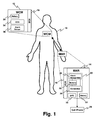
- a patient 10 is equipped with one or more wearable monitors, such as a wearable electrocardiographic (ECG) monitor (WCM) 12 , and a mobile alarm relay system (MAR) 14 (e.g ., mobile phone, PDA or other device which connects to wireless networks), which is utilized to forward alarms generated by the wearable monitor 12 to an external entity.
- ECG electrocardiographic
- MAR mobile alarm relay system
- the wearable monitor 12 can be employed to monitor any physiological function related to the patient 10 .
- Both the wearable monitor 12 and the mobile alarm relay system 14 are equipped with a body communication unit (BCU) 16, 18 .
- the BCUs 16, 18 communicate utilizing a near-field body-coupled communication technology, based on capacitive coupling.
- the wearable monitor 12 is designed to be power efficient and use low energy consumption technologies so that it can be powered by a relatively small battery 20 .
- the monitor communicates the monitored physiological condition to a remote monitoring station via an external connection device 22 , e.g . the transmit/receive portion of a cell phone 24 that communicates with the cell phone network.
- the external connection device 22 includes an alarm recognition component 26 that determines if an alarm condition has been sensed by the wearable monitor 12 .
- a memory 28 is employed by the alarm recognition component 26 to store monitor output before and after the alarm for subsequent retrieval. The memory 28 can store additional data sent by the wearable monitor 12 that relates to a particular physiological function of the patient 10.
- a connection component element 30 connects the mobile relay 14 to the cell phone 24 .
- the mobile relay 14 is preferably designed to be carried in contact or close proximity with a portion of the body, e.g . in a clothing pocket, or wrapped around the wrist, that can carry more weight, particularly a larger battery 32 .
- the mobile alarm relay system 14 is a cell phone hand set that has been modified to include the BCU and other circuitry and has been appropriately programmed.
- the BCUs 16, 18 are associated via body coupled communication. At this stage of communication, security can be set up and a shared authentication key can be exchanged among communication components. After initialization of the BCUs 16, 18 is complete, connections between the BCUs 16, 18 is established and communication can begin. Once communication is started, verification of the communication between the BCUs 16, 18 is monitored to insure that the communication remains active. If communication is inactive, an alarm can be triggered to notify the system of such communication failure.
- the wearable monitor BCU 16 receives physiological information from an electrocardiograph (ECG) sensor 34 or other sensor(s).
- ECG electrocardiograph
- an alarm sensor 36 determines if the output of the monitor calls for an alarm message to be issued.
- the alarm message is communicated via the wearable monitor BCU 16 to the mobile alarm relay system 14 for further relaying.
- all monitored data can be transferred and the alarm recognition circuit 26 of the relay 14 can recognize the alarm condition rather than the alarm signal.
- the alarm signal causes the cell phone to dial a preselected telephone number to report the emergency.
- the cell phone includes a GPS system 38 which communicates the stricken patient's location as well to medical professionals or emergency dispatchers at the receiving station.
- ECG data can be transferred to the mobile alarm relay system 14 with the alarm signal so that the remote receiving station can determine a plan of action based on such particularized data. For example, if the patient's pulse exceeds an alarm threshold, the caregiver can utilize such pulse data to determine the appropriate action to take when administering care to the patient 10 .
- the data is stored into the memory 28 in the mobile alarm relay system 14 or in the wearable monitor 12 so that data can be trended to determine the previous condition of the patient 10 .
- data can be downloaded on a periodic basis from the memory 28 to a remote processor for analysis.
- Fig. 2 illustrates the communication protocol between the wearable monitor 12 and the mobile alarm relay system 14 shown in Fig. 1 .
- a body coupled communication protocol is employed to facilitate communication between the wearable monitor 12 and the mobile alarm relay system 14 .
- Discovery of the wearable monitor 12 is accomplished by sending a discovery signal from the wearable monitor 12 to the mobile alarm relay system 14 once the wearable monitor 12 is introduced to the network ( e.g ., attached to the patient).
- a response signal is transmitted back to the wearable monitor 12 by the mobile alarm relay system 14 .
- Security can be set up by exchanging a shared authentication key between the wearable monitor 12 and mobile alarm relay system 14 .
- An authentication request is communicated from the wearable monitor 12 to the mobile alarm relay system 14 and an authentication key is returned by the mobile alarm relay system 14 to the wearable monitor 12 .
- An association signal is sent from the wearable monitor 12 to the mobile alarm relay system 14 and the mobile alarm relay system 14 returns a confirm signal to verify establishment of a connection between the wearable monitor 12 and mobile alarm relay system 14 on the network.
- a verification signal is sent at various times from the wearable monitor 12 to the mobile alarm relay system 14 .
- the mobile alarm relay system 14 returns a confirm signal to indicate that communication is active between the wearable monitor 12 and the network.
- an alarm signal is transmitted from the wearable monitor 12 to the mobile alarm relay system 14 .
- data is also transmitted with the alarm signal to provide specific information relative to the alarm.
- the alarm signal is further transmitted from the mobile alarm relay system 14 to a remote receiving component (e.g ., transponder) to trigger an external alarm.
- a remote receiving component e.g ., transponder
- the patient 10 is again equipped with a wearable monitor 12 and an identification and relaying component (IRC) 50 .
- the wearable monitor 12 and the relay 50 are each equipped with a body communication unit (BCU) 16, 52 .
- the BCUs 16, 52 communicate utilizing a two-way near field body coupled communication technology, which is based on capacitive coupling with the patient's body.
- the wearable monitor BCU 16 receives alarm information from an electrocardiograph (ECG) sensor 34 detected by the wearable monitor 12 .
- ECG electrocardiograph
- An alarm message is transferred from an alarm sensor 36 via the wearable monitor BCU 16 to the IRC 50 for further relaying.
- the IRC 50 can be placed on a part of the body with no risk of attenuation (e.g . arms or legs).
- the IRC 50 includes an identification (ID) component 54 that provides unique patient identification.
- the IRC 50 further includes an RF system 56 that transmits information for communication via an RF system 58 to a mobile alarm relay system, preferably a cellular phone 60 , preferably using a Bluetooth or other short range, lower power transmission system.
- the cellular phone 60 relays data over the cell phone network to the medical professionals at a receiving station.
- the relay can communicate with a PC or PCA which communicates the alarm and other information over the Internet.
- Other network communications devices are also contemplated. In this manner, patient information gathered at one area of a patient's body can be communicated from a central location on the patient 10 to a global network.
- An alarm recognition component 26 determines if an alarm has been sent by the wearable monitor 12 .
- the memory 28 is employed by the alarm recognition component 26 to store alarms for subsequent retrieval.
- the memory 28 can store additional data sent by the wearable monitor 12 that relates to a particular physiological function of the patient 10 .
- the connection element 30 connects the relay 50 to the cell phone 60 . More specifically, the RF system 56 of the relay 60 interfaces to the external connection device, e.g ., the transmit / receive portion of the cell phone to communicate through the cell phone network.
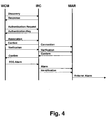
- Fig. 4 illustrates the message flow between the wearable monitor 12 , the relay 50 and the mobile alarm relay system or cell phone 60 of Fig. 3 .
- Communication between the wearable monitor 12 and the relay 50 is facilitated via a body coupled communication technology.
- Communication between the relay 50 and the mobile alarm relay system or cell phone 38 is accomplished via radio frequency (RF ) technology.
- RF radio frequency
- the BCUs 16, 52 of the wearable monitor 12 and the relay 50 are discovered by the body coupled communication network.
- a discovery signal is sent from the wearable monitor 12 to the relay 50 which returns a response signal to the wearable monitor 12 .
- security is established by exchanging a shared authentication key between the wearable monitor 12 and the relay 50 .
- the wearable monitor 12 sends an authentication request to the relay 50 and the relay 50 returns an authentication key to the wearable monitor 12 .
- the connection between the BCUs 16, 52 of the wearable monitor 12 and relay 50 is established via the body coupled communication network.
- An association signal is sent from the wearable monitor 12 to the relay 50 .
- the relay 50 returns a confirm signal to the wearable monitor 12 to verify that communication is established.
- an RF connection between the relay 50 and the cell phone 60 is established after the relay 50 sends a connection signal to the cell phone 60 .
- the connection between the wearable monitor 12 , the relay 50 and the cell phone 60 is monitored and verified.
- the wearable monitor 12 sends a verification signal to the relay 50 and another verification signal is sent from the relay 50 to the cell phone 60 or other mobile alarm relay system.
- the cell phone 60 responds by sending a confirm signal to the relay 50 .
- a confirm signal is also sent from the relay 50 to the wearable monitor 12 . In this manner, the network is notified if a communication failure takes place.
- an ECG alarm signal is sent from the wearable monitor 12 to the relay 50 .
- an alarm signal and an alarm identification signal are sent from the relay 50 to the cell phone 60 or other mobile alarm relay system.
- the cell phone 60 After receiving the alarm and identification signals from the relay 26 , the cell phone 60 sends an external alarm signal to the medical emergency receiving station.
- Fig. 5 illustrates a redundant communication system where the patient 10 is equipped with a wearable monitor (WCM) 70 and a mobile alarm relay system (MAR) 72 , which is utilized for alarm forwarding to an external network.
- An ECG monitors 74 the patient's heart. Additionally or alternatively, an alarm sensor 76 monitors the second ECG or other physiological condition and determines when an alarm triggering aberration has occurred.
- Both the wearable monitor 70 and the relay system 72 are equipped with body communication units (BCUs) 78, 80 as well as with RF (e.g ., Bluetooth) communication units 82, 84 for mutual peer-to-peer communication.
- the relay system 72 is additionally equipped with cellular network connectivity, which is used for alarm forwarding.
- the relay system may be embodied in a cell phone which communicates with the wearable monitor using the body-coupled communication system, when available. However, when the cell phone is separated from the patient, e.g . while recharging, the short range radio communication system is used.
- the wearable monitor 70 and the relay system 72 automatically manage their communication by regular checking both communication links and ensuring that at least one communication link is available at any point in time. If no communication link is available, an automatic warning/notification can be communicated.
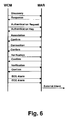
- Fig. 6 illustrates the communication protocol flow between the wearable monitor 70 and the relay system 72 from Fig. 5 .
- This communication can be broken down into three stages: association, verification and alarming.
- the BCUs 78, 80 related to the wearable monitor 70 and the relay system 72 discover each other via the body coupled communication network.
- a discovery signal is transmitted from the wearable monitor 70 to the relay system 72 .
- a shared authentication key is exchanged between the wearable monitor 70 and the relay system 72 to establish secure communication between the wearable monitor 70 and the relay system 72 .
- An authentication request signal is sent from the wearable monitor 70 to the relay system 72 and the relay system 72 returns an authentication key signal to the wearable monitor 70 .
- BCUs 78, 80 of wearable monitor 70 and IRC are connected.
- An association signal is sent via body coupled communication from the wearable monitor 70 to the relay system 72 and a confirm signal is returned from the relay system 72 to the wearable monitor 70 via body coupled communication.
- Second, an additional RF connection is established between the wearable monitor 70 and the relay system 72 .
- a connection signal is sent via RF from the wearable monitor 70 to the relay system 72 .
- the relay system 72 sends a confirm signal back to the wearable monitor 70 to indicate an RF connection is made between the wearable monitor 70 and the relay system 72 .
- Verification provides a regular monitoring of connections (body coupled and RF) between the wearable monitor 70 and the relay system 72 .
- the system is notified if there is a failure of communication with either the body coupled communication or the RF connection.
- a verification signal is sent from the wearable monitor 70 to the relay system 72 .
- the relay system 72 returns a confirm signal to the wearable monitor 70 to verify communication.
- Alarming is provided utilizing both the body coupled communication and the RF connection.
- an ECG alarm is detected by the wearable monitor 70
- an alarm message is transferred to the relay system 72 .
- ECG data can be transferred to the relay system 72 .
- Both connection technologies, body coupled and RF, are employed in parallel to ensure connectivity.
- An ECG alarm signal is sent from the wearable monitor 70 utilizing both body coupled communication and an RF connection.
- an external alarm signal is relayed from the relay system 72 to an external component via a cellular network.
- the wearable monitor 70 or the relay unit 72 connects with any nearby cell phone that is equipped to receive the signal. This assures that the alarm communication reaches the remote medical monitoring station even if the patient's cell phone is unavailable, e.g . dead battery, left out of range, etc.
Abstract
Description
- The following relates to wireless body networks. It finds particular application with alarm relaying from one or more wireless sensors to a cellular phone and further to a surveillance and/or alarm center. However, it is to be appreciated that the invention may also find application in providing communication between wireless sensors and other wireless transponders capable of receiving near field body coupled communication technology.
- Patients are typically monitored of one or more physiological functions when they receive medical attention at a medical facility. For example, it may be desirable to monitor heart function, pulse, blood pressure, blood oxygen level and the like. Conventionally, such monitoring is accomplished utilizing sensors wired to various output devices that can notify medical personnel of one or more conditions. Alternatively, wireless sensors can be employed with wireless networks to transmit such data to one or more wireless transponders such as a display, a monitor, memory, central terminal and the like.
- Such sensors typically provide continuous monitoring of a particular physiological function and an alarm output if a critical event arises. The alarm output can be transmitted utilizing conventional communication technology such as a wired hospital network, radio frequency, Bluetooth or magnetic coupling (B-field), for example. However, when the patient ranges beyond the controlled medical facility communication environment, conventional communication technologies can become unreliable. While a cell phone provides a convenient communication link between a patient and a remote site, direct communication by the monitor in an emergency is more awkward. An ECG monitor can be directly wired to a cell phone, but positioning wires is inconvenient and the wires interfere with normal usage of the cell phone. Cell phones are often compatible with Bluetooth communication protocols. However, in some situations, body attenuation prevents proper signal propagation. For example, if a patient falls down (e.g., due to a heart attack) and covers the chest mounted ECG system, the Bluetooth communication is heavily attenuated by the body and typically disrupted.
- Magnetic coupling communications signals travel readily through the body but consume excessive amounts of energy restricting portability. Due to the weight of batteries, carrying a large battery power supply is inconvenient. In addition, magnetic coupling is typically unidirectional which does not accommodate bi-directional verification routines.
- Typically, communication between the wireless sensor and the mobile phone is fixed due to static configured connectivity. Such static configuration prevents the safe and flexible connection to other nearby mobile phones in an emergency when the primary mobile phone is unavailable. Furthermore, such fixed association inhibits the systems from working reliably in multi-user scenarios.
- In
US 2003/0144581 A1 devices and methods are provided for frequently measuring the concentration of an analyte present in a biological system. A monitoring system having at least two components is employed in order to allow separation of data collection from data processing and display. Such separation allows greater flexibility and convenience for the user. - In
US 2002/0013538 A1 a method for monitoring health signs of an individual is provided including the steps of detecting at least one health sign characteristic of the individual with a sensor unit that is located proximate to the individual; producing a health signal from the sensor unit that indicates at least one health sign of the individual; communicating the health signal from the individual to a receiving unit over a wireless connection; processing the health signal to determine if an emergency condition exists; and providing an indication of an emergency condition to a destination node of a network, wherein operating electrical power is applied to the receiving unit in an initialization mode. The receiving unit determines if the receiving unit has received an identification signal from the sensor unit, and receiving a health signal only from a sensor unit having the received identification signal. - In
US 2003/0125017 A1 a system, method, apparatus, and computer program code for delivering a treatment includes generating a personal area network associated with a patient is described. The personal area network transmits a patient identifier associated with said patient, retrieving treatment data associated with said patient identifier, and operating a treatment device pursuant to said treatment data. - It is the object of the present invention to provide an improved apparatus and method that overcomes the aforementioned limitations and others.
- This object is achieved by a wireless network for monitoring a patient and a method for communicating medical information within a wireless network according to the independent claims.
- Preferred embodiments are defined in the sub claims.
- According to yet another aspect, a method for transmitting medical information within a wireless network includes associating a wearable monitor with a mobile alarm relay system including initializing communication between a first body communication unit associated with the wearable monitor and a second body communication unit associated with the mobile alarm relay system utilizing a near field capacitive body coupled protocol. Secure communication is established between the wearable monitor and the mobile alarm relay system by sending an authentication request from the wearable monitor to the mobile alarm relay system and returning an authentication key from the mobile alarm relay system to the wearable monitor. Communication between the wearable monitor and the mobile alarm relay system is verified to be active by monitoring the connection between the wearable monitor and the mobile alarm relay system, and generating an alarm if the connection becomes inactive. An alarm is triggered if the data transmitted by the wearable monitor is outside of a predetermined threshold including transmitting an alarm message from the wearable monitor to the mobile alarm relay system, and relaying the alarm message from the mobile alarm relay system to an external network.
- One advantage of the present invention is that it facilitates transmission of medical information in an emergency to a patient monitoring station.
- Another advantage is that out-patient monitored medical information is automatically communicated to the patient's medical care professionals.
- Another advantage is that medical information can be relayed to a wireless transponder without risk of attenuation caused by the patient.
- Another advantage is that medical information can be redundantly communicated to insure that such information is received by a wireless transponder.
- Another advantage resides in enabling patient monitors to interconnect with and use existing cell phone networks to communicate medical information.
- Another advantage is that patients who need constant medical monitoring can move freely throughout the community.
- Numerous additional advantages and benefits will become apparent to those of ordinary skill in the art upon reading the following detailed description of the preferred embodiments.
- The invention may take form in various components and arrangements of components, and in various steps and arrangements of steps. The drawings are only for purposes of illustrating the preferred embodiments and are not to be construed as limiting the invention.
-
FIGURE 1 illustrates a body coupled communication network that includes a wireless sensor that communicates to one or more external devices via a mobile alarm relay component. -
FIGURE 2 illustrates a protocol employed inFIGURE 1 to facilitate communication between the wireless sensor, the mobile alarm relay component and one or more external devices. -
FIGURE 3 illustrates a communication network that utilizes a body coupled communication technology and radio frequency technology to transmit information to an external network. -
FIGURE 4 shows a protocol employed inFIGURE 3 to facilitate communication utilizing body coupled communication technology and radio frequency technology. -
FIGURE 5 shows a redundant communication network that employs both a body coupled communication technology and radio frequency technology to transmit information between a wireless sensor and relay component. -
FIGURE 6 shows a protocol employed inFIGURE 5 to facilitate redundant communication between the wireless sensor and the relay component utilizing body coupled communication technology and radio frequency technology. - A
patient 10 is equipped with one or more wearable monitors, such as a wearable electrocardiographic (ECG) monitor (WCM) 12, and a mobile alarm relay system (MAR) 14 (e.g., mobile phone, PDA or other device which connects to wireless networks), which is utilized to forward alarms generated by thewearable monitor 12 to an external entity. It is to be appreciated that thewearable monitor 12 can be employed to monitor any physiological function related to thepatient 10. Both thewearable monitor 12 and the mobilealarm relay system 14 are equipped with a body communication unit (BCU) 16, 18. TheBCUs - The
wearable monitor 12 is designed to be power efficient and use low energy consumption technologies so that it can be powered by a relativelysmall battery 20. The monitor communicates the monitored physiological condition to a remote monitoring station via anexternal connection device 22, e.g. the transmit/receive portion of acell phone 24 that communicates with the cell phone network. Theexternal connection device 22 includes analarm recognition component 26 that determines if an alarm condition has been sensed by thewearable monitor 12. A memory 28 is employed by thealarm recognition component 26 to store monitor output before and after the alarm for subsequent retrieval. The memory 28 can store additional data sent by thewearable monitor 12 that relates to a particular physiological function of thepatient 10. Aconnection component element 30 connects themobile relay 14 to thecell phone 24. - The
mobile relay 14 is preferably designed to be carried in contact or close proximity with a portion of the body, e.g. in a clothing pocket, or wrapped around the wrist, that can carry more weight, particularly alarger battery 32. In the preferred embodiment, the mobilealarm relay system 14 is a cell phone hand set that has been modified to include the BCU and other circuitry and has been appropriately programmed. - First, the
BCUs BCUs BCUs BCUs - The
wearable monitor BCU 16 receives physiological information from an electrocardiograph (ECG)sensor 34 or other sensor(s). Optionally, analarm sensor 36 determines if the output of the monitor calls for an alarm message to be issued. The alarm message is communicated via thewearable monitor BCU 16 to the mobilealarm relay system 14 for further relaying. Alternately, all monitored data can be transferred and thealarm recognition circuit 26 of therelay 14 can recognize the alarm condition rather than the alarm signal. In the preferred cell phone embodiment, the alarm signal causes the cell phone to dial a preselected telephone number to report the emergency. Preferably, the cell phone includes aGPS system 38 which communicates the stricken patient's location as well to medical professionals or emergency dispatchers at the receiving station. - Additionally, ECG data can be transferred to the mobile
alarm relay system 14 with the alarm signal so that the remote receiving station can determine a plan of action based on such particularized data. For example, if the patient's pulse exceeds an alarm threshold, the caregiver can utilize such pulse data to determine the appropriate action to take when administering care to thepatient 10. In another embodiment, the data is stored into the memory 28 in the mobilealarm relay system 14 or in thewearable monitor 12 so that data can be trended to determine the previous condition of thepatient 10. In yet another embodiment, data can be downloaded on a periodic basis from the memory 28 to a remote processor for analysis. -
Fig. 2 illustrates the communication protocol between thewearable monitor 12 and the mobilealarm relay system 14 shown inFig. 1 . A body coupled communication protocol is employed to facilitate communication between thewearable monitor 12 and the mobilealarm relay system 14. Discovery of thewearable monitor 12 is accomplished by sending a discovery signal from thewearable monitor 12 to the mobilealarm relay system 14 once thewearable monitor 12 is introduced to the network (e.g., attached to the patient). A response signal is transmitted back to thewearable monitor 12 by the mobilealarm relay system 14. Security can be set up by exchanging a shared authentication key between thewearable monitor 12 and mobilealarm relay system 14. An authentication request is communicated from thewearable monitor 12 to the mobilealarm relay system 14 and an authentication key is returned by the mobilealarm relay system 14 to thewearable monitor 12. An association signal is sent from thewearable monitor 12 to the mobilealarm relay system 14 and the mobilealarm relay system 14 returns a confirm signal to verify establishment of a connection between thewearable monitor 12 and mobilealarm relay system 14 on the network. - Once communication is established, a verification signal is sent at various times from the
wearable monitor 12 to the mobilealarm relay system 14. When a verification signal is received, the mobilealarm relay system 14 returns a confirm signal to indicate that communication is active between thewearable monitor 12 and the network. In case of an alarm detected by thewearable monitor 12, an alarm signal is transmitted from thewearable monitor 12 to the mobilealarm relay system 14. In one embodiment, data is also transmitted with the alarm signal to provide specific information relative to the alarm. The alarm signal is further transmitted from the mobilealarm relay system 14 to a remote receiving component (e.g., transponder) to trigger an external alarm. When there are a plurality of mobile monitors, analogous protocol is used each to establish communication with the mobilealarm relay system 14. - In
Fig. 3 , thepatient 10 is again equipped with awearable monitor 12 and an identification and relaying component (IRC) 50. Thewearable monitor 12 and therelay 50 are each equipped with a body communication unit (BCU) 16, 52. TheBCUs wearable monitor BCU 16 receives alarm information from an electrocardiograph (ECG)sensor 34 detected by thewearable monitor 12. An alarm message is transferred from analarm sensor 36 via thewearable monitor BCU 16 to theIRC 50 for further relaying. - In contrast to the
wearable monitor 12, which is located in close proximity to the heart, theIRC 50 can be placed on a part of the body with no risk of attenuation (e.g. arms or legs). TheIRC 50 includes an identification (ID)component 54 that provides unique patient identification. TheIRC 50 further includes anRF system 56 that transmits information for communication via anRF system 58 to a mobile alarm relay system, preferably acellular phone 60, preferably using a Bluetooth or other short range, lower power transmission system. In turn, thecellular phone 60 relays data over the cell phone network to the medical professionals at a receiving station. Alternatively or additionally, the relay can communicate with a PC or PCA which communicates the alarm and other information over the Internet. Other network communications devices are also contemplated. In this manner, patient information gathered at one area of a patient's body can be communicated from a central location on the patient 10 to a global network. - An
alarm recognition component 26 determines if an alarm has been sent by thewearable monitor 12. The memory 28 is employed by thealarm recognition component 26 to store alarms for subsequent retrieval. The memory 28 can store additional data sent by thewearable monitor 12 that relates to a particular physiological function of thepatient 10. Theconnection element 30 connects therelay 50 to thecell phone 60. More specifically, theRF system 56 of therelay 60 interfaces to the external connection device, e.g., the transmit / receive portion of the cell phone to communicate through the cell phone network. -
Fig. 4 illustrates the message flow between thewearable monitor 12, therelay 50 and the mobile alarm relay system orcell phone 60 ofFig. 3 . Communication between thewearable monitor 12 and therelay 50 is facilitated via a body coupled communication technology. Communication between therelay 50 and the mobile alarm relay system orcell phone 38 is accomplished via radio frequency (RF) technology. Initially, theBCUs wearable monitor 12 and therelay 50 are discovered by the body coupled communication network. A discovery signal is sent from thewearable monitor 12 to therelay 50 which returns a response signal to thewearable monitor 12. Next, security is established by exchanging a shared authentication key between thewearable monitor 12 and therelay 50. Thewearable monitor 12 sends an authentication request to therelay 50 and therelay 50 returns an authentication key to thewearable monitor 12. Finally, the connection between theBCUs wearable monitor 12 andrelay 50 is established via the body coupled communication network. An association signal is sent from thewearable monitor 12 to therelay 50. Therelay 50 returns a confirm signal to thewearable monitor 12 to verify that communication is established. Additionally, an RF connection between therelay 50 and thecell phone 60 is established after therelay 50 sends a connection signal to thecell phone 60. - The connection between the
wearable monitor 12, therelay 50 and the cell phone 60 (mobile alarm relay system) is monitored and verified. Thewearable monitor 12 sends a verification signal to therelay 50 and another verification signal is sent from therelay 50 to thecell phone 60 or other mobile alarm relay system. Thecell phone 60 responds by sending a confirm signal to therelay 50. A confirm signal is also sent from therelay 50 to thewearable monitor 12. In this manner, the network is notified if a communication failure takes place. Once the communication between thewearable monitor 12, therelay 50 and thecell phone 60 is established, security is implemented and transmission and reception of signals is verified. - If the
wearable monitor 12 detects an alarm, an ECG alarm signal is sent from thewearable monitor 12 to therelay 50. Afterward, an alarm signal and an alarm identification signal are sent from therelay 50 to thecell phone 60 or other mobile alarm relay system. After receiving the alarm and identification signals from therelay 26, thecell phone 60 sends an external alarm signal to the medical emergency receiving station. -
Fig. 5 illustrates a redundant communication system where thepatient 10 is equipped with a wearable monitor (WCM) 70 and a mobile alarm relay system (MAR) 72, which is utilized for alarm forwarding to an external network. An ECG monitors 74 the patient's heart. Additionally or alternatively, analarm sensor 76 monitors the second ECG or other physiological condition and determines when an alarm triggering aberration has occurred. Both thewearable monitor 70 and therelay system 72 are equipped with body communication units (BCUs) 78, 80 as well as with RF (e.g., Bluetooth)communication units relay system 72 is additionally equipped with cellular network connectivity, which is used for alarm forwarding. For example, the relay system may be embodied in a cell phone which communicates with the wearable monitor using the body-coupled communication system, when available. However, when the cell phone is separated from the patient, e.g. while recharging, the short range radio communication system is used. - The
wearable monitor 70 and therelay system 72 automatically manage their communication by regular checking both communication links and ensuring that at least one communication link is available at any point in time. If no communication link is available, an automatic warning/notification can be communicated. -
Fig. 6 illustrates the communication protocol flow between thewearable monitor 70 and therelay system 72 fromFig. 5 . This communication can be broken down into three stages: association, verification and alarming. During the association phase, theBCUs wearable monitor 70 and therelay system 72 discover each other via the body coupled communication network. A discovery signal is transmitted from thewearable monitor 70 to therelay system 72. A shared authentication key is exchanged between thewearable monitor 70 and therelay system 72 to establish secure communication between thewearable monitor 70 and therelay system 72. An authentication request signal is sent from thewearable monitor 70 to therelay system 72 and therelay system 72 returns an authentication key signal to thewearable monitor 70. - In this embodiment, there are two stages of association of the
wearable monitor 70 and therelay system 72. First,BCUs wearable monitor 70 and IRC (not shown) are connected. An association signal is sent via body coupled communication from thewearable monitor 70 to therelay system 72 and a confirm signal is returned from therelay system 72 to thewearable monitor 70 via body coupled communication. Second, an additional RF connection is established between thewearable monitor 70 and therelay system 72. A connection signal is sent via RF from thewearable monitor 70 to therelay system 72. Therelay system 72 sends a confirm signal back to thewearable monitor 70 to indicate an RF connection is made between thewearable monitor 70 and therelay system 72. - Verification provides a regular monitoring of connections (body coupled and RF) between the
wearable monitor 70 and therelay system 72. The system is notified if there is a failure of communication with either the body coupled communication or the RF connection. For both the body coupled communication and the RF connection, a verification signal is sent from thewearable monitor 70 to therelay system 72. Therelay system 72 returns a confirm signal to thewearable monitor 70 to verify communication. - Alarming is provided utilizing both the body coupled communication and the RF connection. In case an ECG alarm is detected by the
wearable monitor 70, an alarm message is transferred to therelay system 72. In addition to the alarm signal, ECG data can be transferred to therelay system 72. Both connection technologies, body coupled and RF, are employed in parallel to ensure connectivity. An ECG alarm signal is sent from thewearable monitor 70 utilizing both body coupled communication and an RF connection. After therelay system 72 receives at least one of the communicated ECG alarm signals, an external alarm signal is relayed from therelay system 72 to an external component via a cellular network. - In another variation, the
wearable monitor 70 or therelay unit 72 connects with any nearby cell phone that is equipped to receive the signal. This assures that the alarm communication reaches the remote medical monitoring station even if the patient's cell phone is unavailable, e.g. dead battery, left out of range, etc. - The invention has been described with reference to the preferred embodiments. Modifications and alterations may occur to others upon reading and understanding the preceding detailed description. It is intended that the invention be construed as including all such modifications and alterations insofar as they come within the scope of the appended claims or the equivalents thereof.
Claims (14)
- A wireless network for monitoring a patient (10), the wireless network comprising: at least one wearable monitor (12, 70) including:a physiological condition sensor (34, 74) coupled to the patient (10) to sense and communicate data related to one physiological function of the patient (10), anda first body communication unit (16, 78) that interfaces with the physiological condition sensor to communicate over the patient (10) utilizing a near field capacitive body coupled protocol; anda relay system (14, 50, 72) including:a second body communication unit (18, 52, 80) that receives data from and communicates with the first body communication unit (16, 78) utilizing the near field capacitive body coupled protocol, andan external communication unit (24, 56, 72) which communicates the data to a remote medical monitoring station,wherein the relay unit includes a cell phone (24, 60, 72), the cell phone including the second body communication unit (18, 52, 80) which receives the data transmitted with the body coupled protocol when the cell phone is touching or closely adjacent the patient and the external communication unit (24, 60, 72) which communicates the data over a cell phone network to the remote station, characterised in that the wearable monitor (12, 70) includes a low power radio frequency transmitter (82) and the cell phone includes a radio frequency receiver (84) which receives the physiological data directly from the wearable monitor when the second body communication unit (18) is not touching or closely adjacent the patient.
- The system according to claim 1, the at least one wearable monitor (12, 70) further including: an alarm sensor (36, 76) that interfaces with the physiological condition sensor (34, 74) to detect whether the sensed physiological condition is outside of a predetermined threshold and causes the first communication unit (16, 78) to send out an alarm signal.
- The system according to claim 1, the wireless body network further including:a relaying component (60) that receives data from one of the wearable monitor (12, 70) external communicating unit (56) and transmits the data to the remote monitoring station.
- The system according to claim 3, wherein the data is transmitted via a radio frequency signal.
- The system according to claim 3, wherein the wireless network further includes: an identification component (54) that provides a unique patient identifier with the data.
- The system according to claim 1, the relaying component (14, 60, 72) broadcasts received data on a cell phone network.
- The system according to claim 1, the physiological condition sensor is one of heart rate, pulse oximetry, respiratory rate, blood pressure, temperature and electrocardiographic activity.
- The system according to claim 1 wherein the external communication unit (56) includes a radio frequency transmitter that transmits a radio frequency signal and wherein the cell phone includes a receiver (58) which receives the radio frequency signal and which retransmits the data on the cell phone network to the remote station.
- The system according to claim 8 wherein the wearable monitor also includes a radio frequency transmitter (82), the cell phone radio frequency receiver receiving the both radio frequency signals.
- A method for communicating medical information within a wireless network, comprising:monitoring a physiological condition of a patient (10) via a sensor (34, 74) coupled to the patient (10);communicating data related to the physiological conditions sensed by the sensor (34, 74) via a first body communication unit (16, 78) that communicates over the patient (10) utilizing a near field capacitive body coupled protocol;receiving data from the at least one wearable monitor (12, 70) by a second body communication unit (18, 52, 80) that communicates with the first body communication unit (16, 78) utilizing the near field capacitive body coupled protocol, wherein the data is received when a cell phone, which includes the second body communication unit (18, 52, 80), is touching or closely adjacent the patient and an external communication unit (24, 60, 72) and wherein the wearable monitor (12, 70) includes a low power radio frequency transmitter (82) and the cell phone includes a radio frequency receiver (84) which receives the physiological data directly from the wearable monitor when the second body communication unit (18) is not touching or closely adjacent the patient; andcommunicating the received data to a remote medical monitoring station over a cell phone network with the external communication unit (24, 60, 72).
- The method according to claim 10, further including: monitoring the sensed physiological condition data and generating an alarm signal in response to the sensed physiological data being outside of a predetermined threshold.
- The method according to claim 10, wherein communicating the received data includes: transmitting a radio frequency signal to a relay system that retransmits the data over the cell phone network.
- The method according to claim 12, further including: communicating the data relative to the sensed physiological condition utilizing a radio frequency protocol; and, with the cell phone, receiving one of the radio frequency protocol and the radio frequency signal and retransmitting the data over the cell phone network.
- The method according to claim 10, wherein the physiological is condition is one of heart rate, pulse oximetry, respiratory rate, blood pressure, temperature and electrocardiographic activity.
Applications Claiming Priority (3)
| Application Number | Priority Date | Filing Date | Title |
|---|---|---|---|
| US63564504P | 2004-12-13 | 2004-12-13 | |
| US67038605P | 2005-04-12 | 2005-04-12 | |
| PCT/IB2005/054063 WO2006064397A2 (en) | 2004-12-13 | 2005-12-05 | Mobile monitoring |
Publications (2)
| Publication Number | Publication Date |
|---|---|
| EP1827214A2 EP1827214A2 (en) | 2007-09-05 |
| EP1827214B1 true EP1827214B1 (en) | 2012-02-15 |
Family
ID=36370968
Family Applications (1)
| Application Number | Title | Priority Date | Filing Date |
|---|---|---|---|
| EP05826721A Not-in-force EP1827214B1 (en) | 2004-12-13 | 2005-12-05 | Mobile monitoring |
Country Status (5)
| Country | Link |
|---|---|
| US (1) | US7978063B2 (en) |
| EP (1) | EP1827214B1 (en) |
| JP (1) | JP5317476B2 (en) |
| AT (1) | ATE545361T1 (en) |
| WO (1) | WO2006064397A2 (en) |
Families Citing this family (229)
| Publication number | Priority date | Publication date | Assignee | Title |
|---|---|---|---|---|
| US7933642B2 (en) | 2001-07-17 | 2011-04-26 | Rud Istvan | Wireless ECG system |
| US7811231B2 (en) | 2002-12-31 | 2010-10-12 | Abbott Diabetes Care Inc. | Continuous glucose monitoring system and methods of use |
| US7587287B2 (en) * | 2003-04-04 | 2009-09-08 | Abbott Diabetes Care Inc. | Method and system for transferring analyte test data |
| US8066639B2 (en) | 2003-06-10 | 2011-11-29 | Abbott Diabetes Care Inc. | Glucose measuring device for use in personal area network |
| WO2005089103A2 (en) | 2004-02-17 | 2005-09-29 | Therasense, Inc. | Method and system for providing data communication in continuous glucose monitoring and management system |
| US9636450B2 (en) | 2007-02-19 | 2017-05-02 | Udo Hoss | Pump system modular components for delivering medication and analyte sensing at seperate insertion sites |
| US7697967B2 (en) | 2005-12-28 | 2010-04-13 | Abbott Diabetes Care Inc. | Method and apparatus for providing analyte sensor insertion |
| US7545272B2 (en) | 2005-02-08 | 2009-06-09 | Therasense, Inc. | RF tag on test strips, test strip vials and boxes |
| EP2392258B1 (en) | 2005-04-28 | 2014-10-08 | Proteus Digital Health, Inc. | Pharma-informatics system |
| US8912908B2 (en) | 2005-04-28 | 2014-12-16 | Proteus Digital Health, Inc. | Communication system with remote activation |
| US9198608B2 (en) | 2005-04-28 | 2015-12-01 | Proteus Digital Health, Inc. | Communication system incorporated in a container |
| US8836513B2 (en) | 2006-04-28 | 2014-09-16 | Proteus Digital Health, Inc. | Communication system incorporated in an ingestible product |
| US8730031B2 (en) | 2005-04-28 | 2014-05-20 | Proteus Digital Health, Inc. | Communication system using an implantable device |
| US8802183B2 (en) | 2005-04-28 | 2014-08-12 | Proteus Digital Health, Inc. | Communication system with enhanced partial power source and method of manufacturing same |
| US20070094128A1 (en) * | 2005-08-29 | 2007-04-26 | Peter Rung | System and method for communications and interface with assets and data sets |
| WO2007028035A2 (en) | 2005-09-01 | 2007-03-08 | Proteus Biomedical, Inc. | Implantable zero-wire communications system |
| US8880138B2 (en) | 2005-09-30 | 2014-11-04 | Abbott Diabetes Care Inc. | Device for channeling fluid and methods of use |
| US7766829B2 (en) | 2005-11-04 | 2010-08-03 | Abbott Diabetes Care Inc. | Method and system for providing basal profile modification in analyte monitoring and management systems |
| US11298058B2 (en) | 2005-12-28 | 2022-04-12 | Abbott Diabetes Care Inc. | Method and apparatus for providing analyte sensor insertion |
| CN100444788C (en) * | 2006-01-17 | 2008-12-24 | 山东优加利信息科技有限公司 | Remote mobile electrophysiological data monitoring method and apparatus based on WAN |
| US7736310B2 (en) | 2006-01-30 | 2010-06-15 | Abbott Diabetes Care Inc. | On-body medical device securement |
| WO2007095093A2 (en) * | 2006-02-09 | 2007-08-23 | Deka Products Limited Partnership | Pumping fluid delivery systems and methods using force application assembly |
| US20090023391A1 (en) * | 2006-02-24 | 2009-01-22 | Koninklijke Philips Electronics N. V. | Wireless body sensor network |
| US7981034B2 (en) | 2006-02-28 | 2011-07-19 | Abbott Diabetes Care Inc. | Smart messages and alerts for an infusion delivery and management system |
| US7826879B2 (en) | 2006-02-28 | 2010-11-02 | Abbott Diabetes Care Inc. | Analyte sensors and methods of use |
| US8002701B2 (en) * | 2006-03-10 | 2011-08-23 | Angel Medical Systems, Inc. | Medical alarm and communication system and methods |
| US8226891B2 (en) | 2006-03-31 | 2012-07-24 | Abbott Diabetes Care Inc. | Analyte monitoring devices and methods therefor |
| US7653425B2 (en) | 2006-08-09 | 2010-01-26 | Abbott Diabetes Care Inc. | Method and system for providing calibration of an analyte sensor in an analyte monitoring system |
| US7620438B2 (en) | 2006-03-31 | 2009-11-17 | Abbott Diabetes Care Inc. | Method and system for powering an electronic device |
| US8374668B1 (en) | 2007-10-23 | 2013-02-12 | Abbott Diabetes Care Inc. | Analyte sensor with lag compensation |
| US8346335B2 (en) | 2008-03-28 | 2013-01-01 | Abbott Diabetes Care Inc. | Analyte sensor calibration management |
| US9392969B2 (en) | 2008-08-31 | 2016-07-19 | Abbott Diabetes Care Inc. | Closed loop control and signal attenuation detection |
| US7618369B2 (en) | 2006-10-02 | 2009-11-17 | Abbott Diabetes Care Inc. | Method and system for dynamically updating calibration parameters for an analyte sensor |
| US8140312B2 (en) | 2007-05-14 | 2012-03-20 | Abbott Diabetes Care Inc. | Method and system for determining analyte levels |
| US8473022B2 (en) | 2008-01-31 | 2013-06-25 | Abbott Diabetes Care Inc. | Analyte sensor with time lag compensation |
| CN105468895A (en) | 2006-05-02 | 2016-04-06 | 普罗透斯数字保健公司 | Patient customized therapeutic regimens |
| CN101495030B (en) * | 2006-07-28 | 2012-12-12 | 皇家飞利浦电子股份有限公司 | Automatic transfer and identification of monitored data with hierarchical key management infrastructure |
| US8206296B2 (en) | 2006-08-07 | 2012-06-26 | Abbott Diabetes Care Inc. | Method and system for providing integrated analyte monitoring and infusion system therapy management |
| US8932216B2 (en) | 2006-08-07 | 2015-01-13 | Abbott Diabetes Care Inc. | Method and system for providing data management in integrated analyte monitoring and infusion system |
| GB0617451D0 (en) * | 2006-09-05 | 2006-10-18 | Medical Prediction Ltd | |
| US7698002B2 (en) | 2006-09-29 | 2010-04-13 | Nellcor Puritan Bennett Llc | Systems and methods for user interface and identification in a medical device |
| US7925511B2 (en) | 2006-09-29 | 2011-04-12 | Nellcor Puritan Bennett Llc | System and method for secure voice identification in a medical device |
| EP2087589B1 (en) | 2006-10-17 | 2011-11-23 | Proteus Biomedical, Inc. | Low voltage oscillator for medical devices |
| KR101611240B1 (en) | 2006-10-25 | 2016-04-11 | 프로테우스 디지털 헬스, 인코포레이티드 | Controlled activation ingestible identifier |
| EP2069004A4 (en) | 2006-11-20 | 2014-07-09 | Proteus Digital Health Inc | Active signal processing personal health signal receivers |
| US8912899B2 (en) | 2007-01-10 | 2014-12-16 | Integrity Tracking, Llc | Wireless sensor network calibration system and method |
| CA2676407A1 (en) | 2007-02-01 | 2008-08-07 | Proteus Biomedical, Inc. | Ingestible event marker systems |
| CA2676280C (en) | 2007-02-14 | 2018-05-22 | Proteus Biomedical, Inc. | In-body power source having high surface area electrode |
| US20080199894A1 (en) | 2007-02-15 | 2008-08-21 | Abbott Diabetes Care, Inc. | Device and method for automatic data acquisition and/or detection |
| US8123686B2 (en) | 2007-03-01 | 2012-02-28 | Abbott Diabetes Care Inc. | Method and apparatus for providing rolling data in communication systems |
| WO2008112577A1 (en) | 2007-03-09 | 2008-09-18 | Proteus Biomedical, Inc. | In-body device having a multi-directional transmitter |
| WO2008112578A1 (en) | 2007-03-09 | 2008-09-18 | Proteus Biomedical, Inc. | In-body device having a deployable antenna |
| EP2146624B1 (en) | 2007-04-14 | 2020-03-25 | Abbott Diabetes Care Inc. | Method and apparatus for providing data processing and control in medical communication system |
| US9204827B2 (en) | 2007-04-14 | 2015-12-08 | Abbott Diabetes Care Inc. | Method and apparatus for providing data processing and control in medical communication system |
| CA2683721C (en) | 2007-04-14 | 2017-05-23 | Abbott Diabetes Care Inc. | Method and apparatus for providing dynamic multi-stage signal amplification in a medical device |
| EP2146625B1 (en) | 2007-04-14 | 2019-08-14 | Abbott Diabetes Care Inc. | Method and apparatus for providing data processing and control in medical communication system |
| US10111608B2 (en) | 2007-04-14 | 2018-10-30 | Abbott Diabetes Care Inc. | Method and apparatus for providing data processing and control in medical communication system |
| US8461985B2 (en) | 2007-05-08 | 2013-06-11 | Abbott Diabetes Care Inc. | Analyte monitoring system and methods |
| US7928850B2 (en) | 2007-05-08 | 2011-04-19 | Abbott Diabetes Care Inc. | Analyte monitoring system and methods |
| US8665091B2 (en) | 2007-05-08 | 2014-03-04 | Abbott Diabetes Care Inc. | Method and device for determining elapsed sensor life |
| US8456301B2 (en) | 2007-05-08 | 2013-06-04 | Abbott Diabetes Care Inc. | Analyte monitoring system and methods |
| US8560038B2 (en) | 2007-05-14 | 2013-10-15 | Abbott Diabetes Care Inc. | Method and apparatus for providing data processing and control in a medical communication system |
| US8444560B2 (en) | 2007-05-14 | 2013-05-21 | Abbott Diabetes Care Inc. | Method and apparatus for providing data processing and control in a medical communication system |
| US10002233B2 (en) | 2007-05-14 | 2018-06-19 | Abbott Diabetes Care Inc. | Method and apparatus for providing data processing and control in a medical communication system |
| US8239166B2 (en) | 2007-05-14 | 2012-08-07 | Abbott Diabetes Care Inc. | Method and apparatus for providing data processing and control in a medical communication system |
| US8103471B2 (en) | 2007-05-14 | 2012-01-24 | Abbott Diabetes Care Inc. | Method and apparatus for providing data processing and control in a medical communication system |
| US9125548B2 (en) | 2007-05-14 | 2015-09-08 | Abbott Diabetes Care Inc. | Method and apparatus for providing data processing and control in a medical communication system |
| US8600681B2 (en) | 2007-05-14 | 2013-12-03 | Abbott Diabetes Care Inc. | Method and apparatus for providing data processing and control in a medical communication system |
| US8260558B2 (en) | 2007-05-14 | 2012-09-04 | Abbott Diabetes Care Inc. | Method and apparatus for providing data processing and control in a medical communication system |
| US8540632B2 (en) | 2007-05-24 | 2013-09-24 | Proteus Digital Health, Inc. | Low profile antenna for in body device |
| EP3533387A3 (en) | 2007-06-21 | 2019-11-13 | Abbott Diabetes Care, Inc. | Health management devices and methods |
| AU2008265542B2 (en) | 2007-06-21 | 2014-07-24 | Abbott Diabetes Care Inc. | Health monitor |
| US8160900B2 (en) | 2007-06-29 | 2012-04-17 | Abbott Diabetes Care Inc. | Analyte monitoring and management device and method to analyze the frequency of user interaction with the device |
| JP2010534003A (en) * | 2007-07-03 | 2010-10-28 | コーニンクレッカ フィリップス エレクトロニクス エヌ ヴィ | Multidimensional identification, authentication, authorization and key distribution system for patient monitoring |
| US8834366B2 (en) | 2007-07-31 | 2014-09-16 | Abbott Diabetes Care Inc. | Method and apparatus for providing analyte sensor calibration |
| US8680986B2 (en) * | 2007-08-01 | 2014-03-25 | Peter Costantino | System and method for facial nerve monitoring during facial surgery |
| US8063770B2 (en) * | 2007-08-01 | 2011-11-22 | Peter Costantino | System and method for facial nerve monitoring |
| US9295412B2 (en) | 2007-08-15 | 2016-03-29 | Integrity Tracking, Llc | Wearable health monitoring device and methods for step detection |
| US8515547B2 (en) | 2007-08-31 | 2013-08-20 | Cardiac Pacemakers, Inc. | Wireless patient communicator for use in a life critical network |
| US9848058B2 (en) | 2007-08-31 | 2017-12-19 | Cardiac Pacemakers, Inc. | Medical data transport over wireless life critical network employing dynamic communication link mapping |
| FI2192946T3 (en) | 2007-09-25 | 2022-11-30 | In-body device with virtual dipole signal amplification | |
| EP2207471B1 (en) * | 2007-10-03 | 2018-04-11 | University of Utah Research Foundation | Miniature wireless biomedical telemetry device |
| US9986911B2 (en) | 2007-10-19 | 2018-06-05 | Smiths Medical Asd, Inc. | Wireless telecommunications system adaptable for patient monitoring |
| US9949641B2 (en) | 2007-10-19 | 2018-04-24 | Smiths Medical Asd, Inc. | Method for establishing a telecommunications system for patient monitoring |
| US8409093B2 (en) | 2007-10-23 | 2013-04-02 | Abbott Diabetes Care Inc. | Assessing measures of glycemic variability |
| US8377031B2 (en) | 2007-10-23 | 2013-02-19 | Abbott Diabetes Care Inc. | Closed loop control system with safety parameters and methods |
| US20090164239A1 (en) | 2007-12-19 | 2009-06-25 | Abbott Diabetes Care, Inc. | Dynamic Display Of Glucose Information |
| CN101904119B (en) | 2007-12-20 | 2015-01-28 | 皇家飞利浦电子股份有限公司 | Capacitive sensing and communicating |
| AT506185B1 (en) * | 2008-01-09 | 2012-01-15 | Nanoident Technologies Ag | DETECTION DEVICE FOR VITAL SIGNS |
| EP2260597A1 (en) * | 2008-02-28 | 2010-12-15 | Philips Intellectual Property & Standards GmbH | Wireless patient monitoring using streaming of medical data with body-coupled communication |
| CA2717862C (en) | 2008-03-05 | 2016-11-22 | Proteus Biomedical, Inc. | Multi-mode communication ingestible event markers and systems, and methods of using the same |
| GB2458139A (en) * | 2008-03-06 | 2009-09-09 | Toumaz Technology Ltd | Monitoring and tracking of wireless sensor devices in a healthcare monitoring system |
| US8924159B2 (en) | 2008-05-30 | 2014-12-30 | Abbott Diabetes Care Inc. | Method and apparatus for providing glycemic control |
| US7826382B2 (en) | 2008-05-30 | 2010-11-02 | Abbott Diabetes Care Inc. | Close proximity communication device and methods |
| US8591410B2 (en) | 2008-05-30 | 2013-11-26 | Abbott Diabetes Care Inc. | Method and apparatus for providing glycemic control |
| ES2696984T3 (en) | 2008-07-08 | 2019-01-21 | Proteus Digital Health Inc | Ingestion event marker data infrastructure |
| WO2010009172A1 (en) | 2008-07-14 | 2010-01-21 | Abbott Diabetes Care Inc. | Closed loop control system interface and methods |
| US8600405B2 (en) | 2008-08-12 | 2013-12-03 | Apogee Technology Consultants, Llc | Location-based recovery device and risk management system for portable computing devices and data |
| MY154217A (en) | 2008-08-13 | 2015-05-15 | Proteus Digital Health Inc | Ingestible circuitry |
| JP2012500698A (en) * | 2008-08-28 | 2012-01-12 | コーニンクレッカ フィリップス エレクトロニクス エヌ ヴィ | Method and system for supplying a patient identification beacon to a patient wearable sensor |
| US8622988B2 (en) | 2008-08-31 | 2014-01-07 | Abbott Diabetes Care Inc. | Variable rate closed loop control and methods |
| US8734422B2 (en) | 2008-08-31 | 2014-05-27 | Abbott Diabetes Care Inc. | Closed loop control with improved alarm functions |
| US20100057040A1 (en) | 2008-08-31 | 2010-03-04 | Abbott Diabetes Care, Inc. | Robust Closed Loop Control And Methods |
| US9943644B2 (en) | 2008-08-31 | 2018-04-17 | Abbott Diabetes Care Inc. | Closed loop control with reference measurement and methods thereof |
| US8986208B2 (en) | 2008-09-30 | 2015-03-24 | Abbott Diabetes Care Inc. | Analyte sensor sensitivity attenuation mitigation |
| US8036748B2 (en) | 2008-11-13 | 2011-10-11 | Proteus Biomedical, Inc. | Ingestible therapy activator system and method |
| SG172077A1 (en) | 2008-12-11 | 2011-07-28 | Proteus Biomedical Inc | Evaluation of gastrointestinal function using portable electroviscerography systems and methods of using the same |
| TWI503101B (en) | 2008-12-15 | 2015-10-11 | Proteus Digital Health Inc | Body-associated receiver and method |
| US9659423B2 (en) | 2008-12-15 | 2017-05-23 | Proteus Digital Health, Inc. | Personal authentication apparatus system and method |
| US9439566B2 (en) | 2008-12-15 | 2016-09-13 | Proteus Digital Health, Inc. | Re-wearable wireless device |
| ES2388488T3 (en) * | 2008-12-23 | 2012-10-15 | Koninklijke Philips Electronics N.V. | Combination of body coupled communication and radio frequency communication |
| WO2010080843A2 (en) | 2009-01-06 | 2010-07-15 | Proteus Biomedical, Inc. | Ingestion-related biofeedback and personalized medical therapy method and system |
| CN102365084B (en) | 2009-01-06 | 2014-04-30 | 普罗秋斯数字健康公司 | Pharmaceutical dosages delivery system |
| EP2208458A1 (en) * | 2009-01-14 | 2010-07-21 | Roche Diagnostics GmbH | Medical monitoring network |
| BRPI1005356A2 (en) * | 2009-02-02 | 2017-12-12 | Koninklijke Philps Electronics N V | transceiver device for processing a medium access control protocol, wireless communications system and mac protocol method |
| US20100198034A1 (en) | 2009-02-03 | 2010-08-05 | Abbott Diabetes Care Inc. | Compact On-Body Physiological Monitoring Devices and Methods Thereof |
| US8319631B2 (en) | 2009-03-04 | 2012-11-27 | Cardiac Pacemakers, Inc. | Modular patient portable communicator for use in life critical network |
| US8812841B2 (en) | 2009-03-04 | 2014-08-19 | Cardiac Pacemakers, Inc. | Communications hub for use in life critical network |
| JP2010213076A (en) * | 2009-03-11 | 2010-09-24 | Ntt Electornics Corp | Electric field communication system |
| US9844333B2 (en) | 2009-03-24 | 2017-12-19 | International Business Machines Corporation | Remote delivery and monitoring of health care |
| WO2010111403A2 (en) | 2009-03-25 | 2010-09-30 | Proteus Biomedical, Inc. | Probablistic pharmacokinetic and pharmacodynamic modeling |
| US8497777B2 (en) | 2009-04-15 | 2013-07-30 | Abbott Diabetes Care Inc. | Analyte monitoring system having an alert |
| WO2010127050A1 (en) | 2009-04-28 | 2010-11-04 | Abbott Diabetes Care Inc. | Error detection in critical repeating data in a wireless sensor system |
| MX2011011506A (en) | 2009-04-28 | 2012-05-08 | Proteus Biomedical Inc | Highly reliable ingestible event markers and methods for using the same. |
| EP2425209A4 (en) | 2009-04-29 | 2013-01-09 | Abbott Diabetes Care Inc | Method and system for providing real time analyte sensor calibration with retrospective backfill |
| WO2010127187A1 (en) | 2009-04-29 | 2010-11-04 | Abbott Diabetes Care Inc. | Method and system for providing data communication in continuous glucose monitoring and management system |
| EP2432458A4 (en) | 2009-05-12 | 2014-02-12 | Proteus Digital Health Inc | Ingestible event markers comprising an ingestible component |
| WO2010138856A1 (en) | 2009-05-29 | 2010-12-02 | Abbott Diabetes Care Inc. | Medical device antenna systems having external antenna configurations |
| JP5271183B2 (en) * | 2009-07-22 | 2013-08-21 | アルプス電気株式会社 | Communication apparatus and communication method |
| US8798934B2 (en) | 2009-07-23 | 2014-08-05 | Abbott Diabetes Care Inc. | Real time management of data relating to physiological control of glucose levels |
| DK3689237T3 (en) | 2009-07-23 | 2021-08-16 | Abbott Diabetes Care Inc | Method of preparation and system for continuous analyte measurement |
| WO2011014851A1 (en) | 2009-07-31 | 2011-02-03 | Abbott Diabetes Care Inc. | Method and apparatus for providing analyte monitoring system calibration accuracy |
| US8558563B2 (en) | 2009-08-21 | 2013-10-15 | Proteus Digital Health, Inc. | Apparatus and method for measuring biochemical parameters |
| EP3001194B1 (en) | 2009-08-31 | 2019-04-17 | Abbott Diabetes Care, Inc. | Medical devices and methods |
| US9314195B2 (en) | 2009-08-31 | 2016-04-19 | Abbott Diabetes Care Inc. | Analyte signal processing device and methods |
| US8993331B2 (en) | 2009-08-31 | 2015-03-31 | Abbott Diabetes Care Inc. | Analyte monitoring system and methods for managing power and noise |
| ES2959131T3 (en) | 2009-08-31 | 2024-02-20 | Abbott Diabetes Care Inc | Displays for a medical device |
| US20110068892A1 (en) * | 2009-09-20 | 2011-03-24 | Awarepoint Corporation | Wireless Tracking System And Method Utilizing Near-Field Communication Devices |
| US8731512B2 (en) * | 2009-09-21 | 2014-05-20 | Generationone | System and method for effecting context-cognizant medical reminders for a patient |
| US20110084132A1 (en) * | 2009-10-08 | 2011-04-14 | At&T Intellectual Property I, L.P. | Devices, Systems and Methods for Secure Remote Medical Diagnostics |
| JP5090585B1 (en) * | 2009-10-19 | 2012-12-05 | ヴェーデクス・アクティーセルスカプ | Hearing aid system with lost partner function |
| TWI517050B (en) | 2009-11-04 | 2016-01-11 | 普羅托斯數位健康公司 | System for supply chain management |
| UA109424C2 (en) | 2009-12-02 | 2015-08-25 | PHARMACEUTICAL PRODUCT, PHARMACEUTICAL TABLE WITH ELECTRONIC MARKER AND METHOD OF MANUFACTURING PHARMACEUTICAL TABLETS | |
| BR112012019212A2 (en) | 2010-02-01 | 2017-06-13 | Proteus Digital Health Inc | data collection system |
| US8526880B2 (en) * | 2010-02-26 | 2013-09-03 | Blackberry Limited | Communications device responsive to near field communications (NFC) to enter locked or unlocked operating modes |
| US10206570B2 (en) | 2010-02-28 | 2019-02-19 | Covidien Lp | Adaptive wireless body networks |
| US9000914B2 (en) * | 2010-03-15 | 2015-04-07 | Welch Allyn, Inc. | Personal area network pairing |
| KR20170121299A (en) | 2010-04-07 | 2017-11-01 | 프로테우스 디지털 헬스, 인코포레이티드 | Miniature ingestible device |
| JP5626623B2 (en) * | 2010-04-09 | 2014-11-19 | 株式会社ハッピーリス | Remote diagnostic system |
| TWI557672B (en) | 2010-05-19 | 2016-11-11 | 波提亞斯數位康健公司 | Computer system and computer-implemented method to track medication from manufacturer to a patient, apparatus and method for confirming delivery of medication to a patient, patient interface device |
| US8957777B2 (en) | 2010-06-30 | 2015-02-17 | Welch Allyn, Inc. | Body area network pairing improvements for clinical workflows |
| US8907782B2 (en) | 2010-06-30 | 2014-12-09 | Welch Allyn, Inc. | Medical devices with proximity detection |
| US8578082B2 (en) | 2010-07-29 | 2013-11-05 | Covidien LLP | Configurable patient monitoring system |
| US11213226B2 (en) | 2010-10-07 | 2022-01-04 | Abbott Diabetes Care Inc. | Analyte monitoring devices and methods |
| JP2014504902A (en) | 2010-11-22 | 2014-02-27 | プロテウス デジタル ヘルス, インコーポレイテッド | Ingestible device with medicinal product |
| WO2012115625A1 (en) * | 2011-02-22 | 2012-08-30 | Research In Motion Limited | Methods and apparatus to connect wireless-enabled devices |
| CN107019515B (en) | 2011-02-28 | 2021-02-26 | 雅培糖尿病护理公司 | Method of displaying sensor readings and analyte monitoring device and method of operating the same |
| US10136845B2 (en) | 2011-02-28 | 2018-11-27 | Abbott Diabetes Care Inc. | Devices, systems, and methods associated with analyte monitoring devices and devices incorporating the same |
| US9131483B2 (en) | 2011-03-10 | 2015-09-08 | Lg Electronics Inc. | Method and apparatus for transreceiving data in medical body area network |
| EP2683291B1 (en) | 2011-03-11 | 2019-07-31 | Proteus Digital Health, Inc. | Wearable personal body associated device with various physical configurations |
| US8671237B2 (en) | 2011-05-31 | 2014-03-11 | Covidien Lp | Patient monitoring platform interface |
| US20120306652A1 (en) * | 2011-06-02 | 2012-12-06 | Nokia Siemens Networks Oy | Ecg alerts |
| US20120306653A1 (en) * | 2011-06-02 | 2012-12-06 | Nokia Siemens Networks Oy | Medical sensor |
| JP5712809B2 (en) * | 2011-06-17 | 2015-05-07 | 富士通株式会社 | COMMUNICATION METHOD, COMMUNICATION SYSTEM, CENTRAL DEVICE, AND COMPUTER PROGRAM |
| US8868616B1 (en) | 2011-07-07 | 2014-10-21 | Integrity Tracking, Llc | Event data monitoring systems and methods |
| US9756874B2 (en) | 2011-07-11 | 2017-09-12 | Proteus Digital Health, Inc. | Masticable ingestible product and communication system therefor |
| WO2015112603A1 (en) | 2014-01-21 | 2015-07-30 | Proteus Digital Health, Inc. | Masticable ingestible product and communication system therefor |
| CN103827914A (en) | 2011-07-21 | 2014-05-28 | 普罗秋斯数字健康公司 | Mobile communication device, system, and method |
| US9211065B2 (en) * | 2011-10-19 | 2015-12-15 | Qualcomm Incorporated | Distributed control of medical devices to avoid effects of interference |
| US9069536B2 (en) | 2011-10-31 | 2015-06-30 | Abbott Diabetes Care Inc. | Electronic devices having integrated reset systems and methods thereof |
| US9235683B2 (en) | 2011-11-09 | 2016-01-12 | Proteus Digital Health, Inc. | Apparatus, system, and method for managing adherence to a regimen |
| US9317656B2 (en) | 2011-11-23 | 2016-04-19 | Abbott Diabetes Care Inc. | Compatibility mechanisms for devices in a continuous analyte monitoring system and methods thereof |
| US8710993B2 (en) | 2011-11-23 | 2014-04-29 | Abbott Diabetes Care Inc. | Mitigating single point failure of devices in an analyte monitoring system and methods thereof |
| WO2013078426A2 (en) | 2011-11-25 | 2013-05-30 | Abbott Diabetes Care Inc. | Analyte monitoring system and methods of use |
| US20130144536A1 (en) * | 2011-12-06 | 2013-06-06 | Welch Allyn, Inc. | Medical Device with Wireless Communication Bus |
| US20130171956A1 (en) * | 2012-01-03 | 2013-07-04 | Michael Maurice Lever | Man-overboard radio |
| JP6522342B2 (en) * | 2012-01-06 | 2019-05-29 | シグニファイ ホールディング ビー ヴィ | Emergency response and tracking using lighting networks |
| US8942662B2 (en) * | 2012-02-16 | 2015-01-27 | The United States of America, as represented by the Secretary, Department of Health and Human Services, Center for Disease Control and Prevention | System and method to predict and avoid musculoskeletal injuries |
| US9008658B2 (en) * | 2012-06-06 | 2015-04-14 | Welch Allyn, Inc. | Using near-field communication both for out-of-band pairing and physiological data transfer |
| JP2015534539A (en) | 2012-07-23 | 2015-12-03 | プロテウス デジタル ヘルス, インコーポレイテッド | Technique for producing an ingestible event marker with an ingestible component |
| EP3395252A1 (en) | 2012-08-30 | 2018-10-31 | Abbott Diabetes Care, Inc. | Dropout detection in continuous analyte monitoring data during data excursions |
| JP6015265B2 (en) * | 2012-09-13 | 2016-10-26 | ヤマハ株式会社 | Proximity communication system |
| US9968306B2 (en) * | 2012-09-17 | 2018-05-15 | Abbott Diabetes Care Inc. | Methods and apparatuses for providing adverse condition notification with enhanced wireless communication range in analyte monitoring systems |
| WO2014049789A1 (en) * | 2012-09-27 | 2014-04-03 | 株式会社メディキタス | Biometric information transmission device |
| US9268909B2 (en) | 2012-10-18 | 2016-02-23 | Proteus Digital Health, Inc. | Apparatus, system, and method to adaptively optimize power dissipation and broadcast power in a power source for a communication device |
| EP2923346A4 (en) * | 2012-11-22 | 2016-11-16 | Geob Internat Sdn Bhd | A medical monitoring system |
| EP2747040A1 (en) * | 2012-12-21 | 2014-06-25 | Gemalto SA | Converting communication device |
| WO2014120669A1 (en) | 2013-01-29 | 2014-08-07 | Proteus Digital Health, Inc. | Highly-swellable polymeric films and compositions comprising the same |
| EP2765720A1 (en) * | 2013-02-06 | 2014-08-13 | Koninklijke Philips N.V. | Body coupled communication system |
| US20150372770A1 (en) * | 2013-02-06 | 2015-12-24 | Koninklijke Philips N.V. | Body coupled communiication system |
| US9681311B2 (en) | 2013-03-15 | 2017-06-13 | Elwha Llc | Portable wireless node local cooperation |
| US10175376B2 (en) | 2013-03-15 | 2019-01-08 | Proteus Digital Health, Inc. | Metal detector apparatus, system, and method |
| US9491637B2 (en) * | 2013-03-15 | 2016-11-08 | Elwha Llc | Portable wireless node auxiliary relay |
| US9608862B2 (en) | 2013-03-15 | 2017-03-28 | Elwha Llc | Frequency accommodation |
| US9793596B2 (en) | 2013-03-15 | 2017-10-17 | Elwha Llc | Facilitating wireless communication in conjunction with orientation position |
| WO2014151929A1 (en) | 2013-03-15 | 2014-09-25 | Proteus Digital Health, Inc. | Personal authentication apparatus system and method |
| US9247375B2 (en) * | 2013-04-25 | 2016-01-26 | Olympus Corporation | Disaster rescue mode for body area networks |
| JP6054238B2 (en) * | 2013-04-26 | 2016-12-27 | 株式会社東芝 | Electronic device and communication control method |
| GB2513900B (en) | 2013-05-10 | 2015-06-03 | G4S Monitoring Technologies Ltd | Person identification system |
| CN103230261B (en) * | 2013-05-20 | 2014-12-03 | 成都实唯物联网科技有限公司 | Physiological information monitoring system and monitoring method |
| JP6511439B2 (en) | 2013-06-04 | 2019-05-15 | プロテウス デジタル ヘルス, インコーポレイテッド | Systems, devices, and methods for data collection and outcome assessment |
| US9796576B2 (en) | 2013-08-30 | 2017-10-24 | Proteus Digital Health, Inc. | Container with electronically controlled interlock |
| EP3047618B1 (en) | 2013-09-20 | 2023-11-08 | Otsuka Pharmaceutical Co., Ltd. | Methods, devices and systems for receiving and decoding a signal in the presence of noise using slices and warping |
| WO2015044722A1 (en) | 2013-09-24 | 2015-04-02 | Proteus Digital Health, Inc. | Method and apparatus for use with received electromagnetic signal at a frequency not known exactly in advance |
| US10716475B2 (en) * | 2013-09-25 | 2020-07-21 | Zoll Medical Corporation | Localized monitoring |
| US10084880B2 (en) | 2013-11-04 | 2018-09-25 | Proteus Digital Health, Inc. | Social media networking based on physiologic information |
| JP2015126804A (en) * | 2013-12-27 | 2015-07-09 | 株式会社日立システムズ | Wearable device and data collection means |
| US9452293B2 (en) * | 2014-06-19 | 2016-09-27 | Inspire Medical Systems, Inc. | Hybrid communication channel for communicating with an implantable medical device |
| US9700261B2 (en) | 2014-09-22 | 2017-07-11 | Oticon A/S | Hearing assistance system comprising electrodes for picking up brain wave signals |
| US10342485B2 (en) | 2014-10-01 | 2019-07-09 | Covidien Lp | Removable base for wearable medical monitor |
| US9473878B2 (en) * | 2014-12-25 | 2016-10-18 | Intel Corporation | Apparatus, method and system of managing a wearable device ensemble |
| EP3256995A1 (en) * | 2015-02-09 | 2017-12-20 | Koninklijke Philips N.V. | Wearable devices as a service |
| JP6884498B2 (en) * | 2015-02-27 | 2021-06-09 | フクダ電子株式会社 | Biometric information monitor |
| WO2016183524A1 (en) * | 2015-05-14 | 2016-11-17 | Abbott Diabetes Care Inc. | Systems, devices, and methods for monitoring medical devices |
| CN108024765B (en) | 2015-07-10 | 2021-06-11 | 雅培糖尿病护理公司 | System, device and method for dynamic glucose curve response to physiological parameters |
| US11051543B2 (en) | 2015-07-21 | 2021-07-06 | Otsuka Pharmaceutical Co. Ltd. | Alginate on adhesive bilayer laminate film |
| USD804042S1 (en) | 2015-12-10 | 2017-11-28 | Covidien Lp | Wearable medical monitor |
| USD794206S1 (en) | 2015-12-18 | 2017-08-08 | Covidien Lp | Combined strap and cradle for wearable medical monitor |
| CN109843149B (en) | 2016-07-22 | 2020-07-07 | 普罗秋斯数字健康公司 | Electromagnetic sensing and detection of ingestible event markers |
| US10460590B2 (en) * | 2016-07-26 | 2019-10-29 | Tyco Integrated Security, LLC | Method and system for mobile duress alarm |
| US10204498B2 (en) | 2016-10-02 | 2019-02-12 | Marquette Trishaun | System for monitoring state of user and related methods |
| CN109963499B (en) | 2016-10-26 | 2022-02-25 | 大冢制药株式会社 | Method for manufacturing capsules with ingestible event markers |
| WO2018175489A1 (en) | 2017-03-21 | 2018-09-27 | Abbott Diabetes Care Inc. | Methods, devices and system for providing diabetic condition diagnosis and therapy |
| JP7387252B2 (en) * | 2018-03-22 | 2023-11-28 | 日本光電工業株式会社 | Signal relay equipment and biological information monitoring system |
| US11297568B2 (en) | 2019-01-18 | 2022-04-05 | T-Mobile Usa, Inc. | Location-based apparatus management |
| US11252031B2 (en) | 2019-11-20 | 2022-02-15 | T-Mobile Usa, Inc. | Coordinated management of IoT device power consumption and network congestion |
| WO2021107864A1 (en) * | 2019-11-27 | 2021-06-03 | National University Of Singapore | Methods and systems for near-field communication |
| US11074799B1 (en) * | 2020-01-24 | 2021-07-27 | T-Mobile Usa, Inc. | Modular tracking device |
| US11766183B2 (en) | 2020-05-13 | 2023-09-26 | Geoffry Weng Leng TAN | System and method for analyzing a physiological condition of a user |
Family Cites Families (18)
| Publication number | Priority date | Publication date | Assignee | Title |
|---|---|---|---|---|
| EP0824799B1 (en) * | 1995-05-08 | 2002-08-21 | Massachusetts Institute Of Technology | System for non-contact sensing and signalling using human body as signal transmission medium |
| US5796827A (en) * | 1996-11-14 | 1998-08-18 | International Business Machines Corporation | System and method for near-field human-body coupling for encrypted communication with identification cards |
| US6223018B1 (en) * | 1996-12-12 | 2001-04-24 | Nippon Telegraph And Telephone Corporation | Intra-body information transfer device |
| JPH1142214A (en) * | 1997-07-23 | 1999-02-16 | Teruo Ido | Portable wireless electrocardiogram monitor |
| US20020013538A1 (en) * | 1997-09-30 | 2002-01-31 | David Teller | Method and apparatus for health signs monitoring |
| US6211799B1 (en) * | 1997-11-06 | 2001-04-03 | Massachusetts Institute Of Technology | Method and apparatus for transbody transmission of power and information |
| JP3697629B2 (en) * | 1999-09-13 | 2005-09-21 | 日本光電工業株式会社 | Communication system for biological signals |
| US6166644A (en) * | 1998-09-10 | 2000-12-26 | Senior Technologies, Inc. | Patient monitoring system |
| CA2666434A1 (en) * | 1998-10-08 | 2000-04-13 | Medtronic Minimed, Inc. | Telemetered characteristic monitor system |
| US7088233B2 (en) * | 1998-10-23 | 2006-08-08 | Royal Thoughts, Llc | Personal medical device communication system and method |
| US6602469B1 (en) * | 1998-11-09 | 2003-08-05 | Lifestream Technologies, Inc. | Health monitoring and diagnostic device and network-based health assessment and medical records maintenance system |
| EP1135052A1 (en) * | 1999-02-12 | 2001-09-26 | Cygnus, Inc. | Devices and methods for frequent measurement of an analyte present in a biological system |
| US6287252B1 (en) * | 1999-06-30 | 2001-09-11 | Monitrak | Patient monitor |
| WO2001037438A1 (en) * | 1999-11-15 | 2001-05-25 | Interlogix, Inc. | Highly reliable power line communications system |
| US7051120B2 (en) * | 2001-12-28 | 2006-05-23 | International Business Machines Corporation | Healthcare personal area identification network method and system |
| JP2003220052A (en) * | 2002-01-29 | 2003-08-05 | Junichi Ninomiya | Remote monitoring method of blood oxygen concentration of patient and remote monitoring system thereof |
| DE10233071B4 (en) | 2002-07-19 | 2006-11-02 | Vita Phone Gmbh | Method, mobile telephone and system for the measurement, analysis and wireless transmission of cardiac potential |
| US7542721B1 (en) * | 2003-04-08 | 2009-06-02 | At&T Mobility Ii Llc | Systems and methods for providing non-dedicated wireless backup service for monitored security systems via Bluetooth |
-
2005
- 2005-12-05 US US11/720,892 patent/US7978063B2/en not_active Expired - Fee Related
- 2005-12-05 WO PCT/IB2005/054063 patent/WO2006064397A2/en active Application Filing
- 2005-12-05 AT AT05826721T patent/ATE545361T1/en active
- 2005-12-05 JP JP2007545050A patent/JP5317476B2/en not_active Expired - Fee Related
- 2005-12-05 EP EP05826721A patent/EP1827214B1/en not_active Not-in-force
Also Published As
| Publication number | Publication date |
|---|---|
| WO2006064397A2 (en) | 2006-06-22 |
| US7978063B2 (en) | 2011-07-12 |
| US20090231125A1 (en) | 2009-09-17 |
| JP5317476B2 (en) | 2013-10-16 |
| ATE545361T1 (en) | 2012-03-15 |
| WO2006064397A3 (en) | 2006-11-09 |
| JP2008522703A (en) | 2008-07-03 |
| EP1827214A2 (en) | 2007-09-05 |
Similar Documents
| Publication | Publication Date | Title |
|---|---|---|
| EP1827214B1 (en) | Mobile monitoring | |
| CN100581445C (en) | Mobile monitoring | |
| JP6118028B2 (en) | Wireless monitoring system and method with dual mode alarm | |
| CN100459539C (en) | Wireless subject monitoring system | |
| CN101040286B (en) | System for automatic continuous and reliable patient identification for association of wireless medical devices to patients | |
| US6443890B1 (en) | Wireless internet bio-telemetry monitoring system | |
| US8058986B2 (en) | Method for automatic association devices to a patient and concurrent creation of a patient record | |
| EP2531100B1 (en) | Portable eeg monitor system with wireless communication | |
| JP2008522703A5 (en) | ||
| CN102265534B (en) | Combining body-coupled communication and radio frequency communication | |
| US20150305690A1 (en) | Medical Monitoring System | |
| US20030109988A1 (en) | Three-dimensional GPS-assisted tracking device | |
| CN101516256A (en) | IP based monitoring and alarming | |
| CN104042196A (en) | Real-time health monitoring and intelligent pre-warning system and method | |
| KR100723655B1 (en) | A remote monitering system using a mobile phone | |
| CN102068261A (en) | Safety monitor | |
| CN102805615A (en) | Smart phone application-based life sign monitoring alarm | |
| KR20080109371A (en) | Emergency rescue system | |
| Wu et al. | WAITER: A wearable personal healthcare and emergency aid system | |
| Varshney | Wireless networks for enhanced monitoring of patients | |
| CN112204935A (en) | Method for establishing Bluetooth pairing of patient monitor system and patient monitor system | |
| HU227955B1 (en) | Method of operating a data processing system as well as a wireless device used for monitoring and continuous controlling vital functions | |
| Moron et al. | J2ME and smart phones as platform for a Bluetooth Body Area Network for Patient-telemonitoring | |
| IL99620A (en) | Medical rescue system | |
| Morón et al. | A smart phone-based personal area network for remote monitoring of biosignals |
Legal Events
| Date | Code | Title | Description |
|---|---|---|---|
| PUAI | Public reference made under article 153(3) epc to a published international application that has entered the european phase |
Free format text: ORIGINAL CODE: 0009012 |
|
| 17P | Request for examination filed |
Effective date: 20070713 |
|
| AK | Designated contracting states |
Kind code of ref document: A2 Designated state(s): AT BE BG CH CY CZ DE DK EE ES FI FR GB GR HU IE IS IT LI LT LU LV MC NL PL PT RO SE SI SK TR |
|
| DAX | Request for extension of the european patent (deleted) | ||
| 17Q | First examination report despatched |
Effective date: 20080729 |
|
| R17C | First examination report despatched (corrected) |
Effective date: 20080811 |
|
| GRAP | Despatch of communication of intention to grant a patent |
Free format text: ORIGINAL CODE: EPIDOSNIGR1 |
|
| GRAS | Grant fee paid |
Free format text: ORIGINAL CODE: EPIDOSNIGR3 |
|
| GRAA | (expected) grant |
Free format text: ORIGINAL CODE: 0009210 |
|
| STAA | Information on the status of an ep patent application or granted ep patent |
Free format text: STATUS: THE PATENT HAS BEEN GRANTED |
|
| AK | Designated contracting states |
Kind code of ref document: B1 Designated state(s): AT BE BG CH CY CZ DE DK EE ES FI FR GB GR HU IE IS IT LI LT LU LV MC NL PL PT RO SE SI SK TR |
|
| REG | Reference to a national code |
Ref country code: GB Ref legal event code: FG4D Ref country code: CH Ref legal event code: EP |
|
| REG | Reference to a national code |
Ref country code: IE Ref legal event code: FG4D |
|
| REG | Reference to a national code |
Ref country code: AT Ref legal event code: REF Ref document number: 545361 Country of ref document: AT Kind code of ref document: T Effective date: 20120315 |
|
| REG | Reference to a national code |
Ref country code: DE Ref legal event code: R096 Ref document number: 602005032726 Country of ref document: DE Effective date: 20120419 |
|
| REG | Reference to a national code |
Ref country code: NL Ref legal event code: VDEP Effective date: 20120215 |
|
| LTIE | Lt: invalidation of european patent or patent extension |
Effective date: 20120215 |
|
| PG25 | Lapsed in a contracting state [announced via postgrant information from national office to epo] |
Ref country code: IS Free format text: LAPSE BECAUSE OF FAILURE TO SUBMIT A TRANSLATION OF THE DESCRIPTION OR TO PAY THE FEE WITHIN THE PRESCRIBED TIME-LIMIT Effective date: 20120615 Ref country code: LT Free format text: LAPSE BECAUSE OF FAILURE TO SUBMIT A TRANSLATION OF THE DESCRIPTION OR TO PAY THE FEE WITHIN THE PRESCRIBED TIME-LIMIT Effective date: 20120215 Ref country code: NL Free format text: LAPSE BECAUSE OF FAILURE TO SUBMIT A TRANSLATION OF THE DESCRIPTION OR TO PAY THE FEE WITHIN THE PRESCRIBED TIME-LIMIT Effective date: 20120215 |
|
| PG25 | Lapsed in a contracting state [announced via postgrant information from national office to epo] |
Ref country code: FI Free format text: LAPSE BECAUSE OF FAILURE TO SUBMIT A TRANSLATION OF THE DESCRIPTION OR TO PAY THE FEE WITHIN THE PRESCRIBED TIME-LIMIT Effective date: 20120215 Ref country code: LV Free format text: LAPSE BECAUSE OF FAILURE TO SUBMIT A TRANSLATION OF THE DESCRIPTION OR TO PAY THE FEE WITHIN THE PRESCRIBED TIME-LIMIT Effective date: 20120215 Ref country code: GR Free format text: LAPSE BECAUSE OF FAILURE TO SUBMIT A TRANSLATION OF THE DESCRIPTION OR TO PAY THE FEE WITHIN THE PRESCRIBED TIME-LIMIT Effective date: 20120516 Ref country code: PL Free format text: LAPSE BECAUSE OF FAILURE TO SUBMIT A TRANSLATION OF THE DESCRIPTION OR TO PAY THE FEE WITHIN THE PRESCRIBED TIME-LIMIT Effective date: 20120215 Ref country code: BE Free format text: LAPSE BECAUSE OF FAILURE TO SUBMIT A TRANSLATION OF THE DESCRIPTION OR TO PAY THE FEE WITHIN THE PRESCRIBED TIME-LIMIT Effective date: 20120215 Ref country code: PT Free format text: LAPSE BECAUSE OF FAILURE TO SUBMIT A TRANSLATION OF THE DESCRIPTION OR TO PAY THE FEE WITHIN THE PRESCRIBED TIME-LIMIT Effective date: 20120615 |
|
| REG | Reference to a national code |
Ref country code: AT Ref legal event code: MK05 Ref document number: 545361 Country of ref document: AT Kind code of ref document: T Effective date: 20120215 |
|
| PG25 | Lapsed in a contracting state [announced via postgrant information from national office to epo] |
Ref country code: CY Free format text: LAPSE BECAUSE OF FAILURE TO SUBMIT A TRANSLATION OF THE DESCRIPTION OR TO PAY THE FEE WITHIN THE PRESCRIBED TIME-LIMIT Effective date: 20120215 |
|
| PG25 | Lapsed in a contracting state [announced via postgrant information from national office to epo] |
Ref country code: EE Free format text: LAPSE BECAUSE OF FAILURE TO SUBMIT A TRANSLATION OF THE DESCRIPTION OR TO PAY THE FEE WITHIN THE PRESCRIBED TIME-LIMIT Effective date: 20120215 Ref country code: DK Free format text: LAPSE BECAUSE OF FAILURE TO SUBMIT A TRANSLATION OF THE DESCRIPTION OR TO PAY THE FEE WITHIN THE PRESCRIBED TIME-LIMIT Effective date: 20120215 Ref country code: CZ Free format text: LAPSE BECAUSE OF FAILURE TO SUBMIT A TRANSLATION OF THE DESCRIPTION OR TO PAY THE FEE WITHIN THE PRESCRIBED TIME-LIMIT Effective date: 20120215 Ref country code: SE Free format text: LAPSE BECAUSE OF FAILURE TO SUBMIT A TRANSLATION OF THE DESCRIPTION OR TO PAY THE FEE WITHIN THE PRESCRIBED TIME-LIMIT Effective date: 20120215 Ref country code: RO Free format text: LAPSE BECAUSE OF FAILURE TO SUBMIT A TRANSLATION OF THE DESCRIPTION OR TO PAY THE FEE WITHIN THE PRESCRIBED TIME-LIMIT Effective date: 20120215 Ref country code: SI Free format text: LAPSE BECAUSE OF FAILURE TO SUBMIT A TRANSLATION OF THE DESCRIPTION OR TO PAY THE FEE WITHIN THE PRESCRIBED TIME-LIMIT Effective date: 20120215 |
|
| PG25 | Lapsed in a contracting state [announced via postgrant information from national office to epo] |
Ref country code: IT Free format text: LAPSE BECAUSE OF FAILURE TO SUBMIT A TRANSLATION OF THE DESCRIPTION OR TO PAY THE FEE WITHIN THE PRESCRIBED TIME-LIMIT Effective date: 20120215 Ref country code: SK Free format text: LAPSE BECAUSE OF FAILURE TO SUBMIT A TRANSLATION OF THE DESCRIPTION OR TO PAY THE FEE WITHIN THE PRESCRIBED TIME-LIMIT Effective date: 20120215 |
|
| PLBE | No opposition filed within time limit |
Free format text: ORIGINAL CODE: 0009261 |
|
| STAA | Information on the status of an ep patent application or granted ep patent |
Free format text: STATUS: NO OPPOSITION FILED WITHIN TIME LIMIT |
|
| 26N | No opposition filed |
Effective date: 20121116 |
|
| PG25 | Lapsed in a contracting state [announced via postgrant information from national office to epo] |
Ref country code: AT Free format text: LAPSE BECAUSE OF FAILURE TO SUBMIT A TRANSLATION OF THE DESCRIPTION OR TO PAY THE FEE WITHIN THE PRESCRIBED TIME-LIMIT Effective date: 20120215 |
|
| REG | Reference to a national code |
Ref country code: DE Ref legal event code: R081 Ref document number: 602005032726 Country of ref document: DE Owner name: PHILIPS INTELLECTUAL PROPERTY & STANDARDS GMBH, DE Free format text: FORMER OWNER: KONINKLIJKE PHILIPS ELECTRONICS N.V., EINDHOVEN, NL Effective date: 20130122 Ref country code: DE Ref legal event code: R097 Ref document number: 602005032726 Country of ref document: DE Effective date: 20121116 Ref country code: DE Ref legal event code: R081 Ref document number: 602005032726 Country of ref document: DE Owner name: PHILIPS INTELLECTUAL PROPERTY & STANDARDS GMBH, DE Free format text: FORMER OWNER: KONINKLIJKE PHILIPS ELECTRONICS N.V., EINDHOVEN, NL Effective date: 20120223 Ref country code: DE Ref legal event code: R081 Ref document number: 602005032726 Country of ref document: DE Owner name: PHILIPS DEUTSCHLAND GMBH, DE Free format text: FORMER OWNER: KONINKLIJKE PHILIPS ELECTRONICS N.V., EINDHOVEN, NL Effective date: 20130122 Ref country code: DE Ref legal event code: R081 Ref document number: 602005032726 Country of ref document: DE Owner name: PHILIPS DEUTSCHLAND GMBH, DE Free format text: FORMER OWNER: KONINKLIJKE PHILIPS ELECTRONICS N.V., EINDHOVEN, NL Effective date: 20120223 Ref country code: DE Ref legal event code: R081 Ref document number: 602005032726 Country of ref document: DE Owner name: PHILIPS GMBH, DE Free format text: FORMER OWNER: KONINKLIJKE PHILIPS ELECTRONICS N.V., EINDHOVEN, NL Effective date: 20120223 Ref country code: DE Ref legal event code: R081 Ref document number: 602005032726 Country of ref document: DE Owner name: PHILIPS GMBH, DE Free format text: FORMER OWNER: KONINKLIJKE PHILIPS ELECTRONICS N.V., EINDHOVEN, NL Effective date: 20130122 |
|
| PG25 | Lapsed in a contracting state [announced via postgrant information from national office to epo] |
Ref country code: ES Free format text: LAPSE BECAUSE OF FAILURE TO SUBMIT A TRANSLATION OF THE DESCRIPTION OR TO PAY THE FEE WITHIN THE PRESCRIBED TIME-LIMIT Effective date: 20120526 |
|
| PG25 | Lapsed in a contracting state [announced via postgrant information from national office to epo] |
Ref country code: MC Free format text: LAPSE BECAUSE OF NON-PAYMENT OF DUE FEES Effective date: 20121231 Ref country code: BG Free format text: LAPSE BECAUSE OF FAILURE TO SUBMIT A TRANSLATION OF THE DESCRIPTION OR TO PAY THE FEE WITHIN THE PRESCRIBED TIME-LIMIT Effective date: 20120515 |
|
| REG | Reference to a national code |
Ref country code: CH Ref legal event code: PL |
|
| REG | Reference to a national code |
Ref country code: IE Ref legal event code: MM4A |
|
| PG25 | Lapsed in a contracting state [announced via postgrant information from national office to epo] |
Ref country code: LI Free format text: LAPSE BECAUSE OF NON-PAYMENT OF DUE FEES Effective date: 20121231 Ref country code: CH Free format text: LAPSE BECAUSE OF NON-PAYMENT OF DUE FEES Effective date: 20121231 Ref country code: IE Free format text: LAPSE BECAUSE OF NON-PAYMENT OF DUE FEES Effective date: 20121205 |
|
| REG | Reference to a national code |
Ref country code: DE Ref legal event code: R081 Ref document number: 602005032726 Country of ref document: DE Owner name: PHILIPS GMBH, DE Free format text: FORMER OWNER: PHILIPS INTELLECTUAL PROPERTY & STANDARDS GMBH, 52066 AACHEN, DE Effective date: 20140331 Ref country code: DE Ref legal event code: R081 Ref document number: 602005032726 Country of ref document: DE Owner name: PHILIPS DEUTSCHLAND GMBH, DE Free format text: FORMER OWNER: PHILIPS INTELLECTUAL PROPERTY & STANDARDS GMBH, 52066 AACHEN, DE Effective date: 20140331 |
|
| PG25 | Lapsed in a contracting state [announced via postgrant information from national office to epo] |
Ref country code: LU Free format text: LAPSE BECAUSE OF NON-PAYMENT OF DUE FEES Effective date: 20121205 |
|
| PG25 | Lapsed in a contracting state [announced via postgrant information from national office to epo] |
Ref country code: HU Free format text: LAPSE BECAUSE OF FAILURE TO SUBMIT A TRANSLATION OF THE DESCRIPTION OR TO PAY THE FEE WITHIN THE PRESCRIBED TIME-LIMIT Effective date: 20051205 |
|
| REG | Reference to a national code |
Ref country code: FR Ref legal event code: CA Effective date: 20141126 Ref country code: FR Ref legal event code: CD Owner name: KONINKLIJKE PHILIPS ELECTRONICS N.V., NL Effective date: 20141126 |
|
| REG | Reference to a national code |
Ref country code: DE Ref legal event code: R081 Ref document number: 602005032726 Country of ref document: DE Owner name: PHILIPS GMBH, DE Free format text: FORMER OWNER: PHILIPS DEUTSCHLAND GMBH, 20099 HAMBURG, DE |
|
| REG | Reference to a national code |
Ref country code: FR Ref legal event code: PLFP Year of fee payment: 11 |
|
| REG | Reference to a national code |
Ref country code: FR Ref legal event code: PLFP Year of fee payment: 12 |
|
| REG | Reference to a national code |
Ref country code: FR Ref legal event code: PLFP Year of fee payment: 13 |
|
| PGFP | Annual fee paid to national office [announced via postgrant information from national office to epo] |
Ref country code: FR Payment date: 20191230 Year of fee payment: 15 |
|
| PGFP | Annual fee paid to national office [announced via postgrant information from national office to epo] |
Ref country code: TR Payment date: 20191204 Year of fee payment: 15 |
|
| PGFP | Annual fee paid to national office [announced via postgrant information from national office to epo] |
Ref country code: GB Payment date: 20191226 Year of fee payment: 15 Ref country code: DE Payment date: 20191230 Year of fee payment: 15 |
|
| REG | Reference to a national code |
Ref country code: DE Ref legal event code: R081 Ref document number: 602005032726 Country of ref document: DE Owner name: PHILIPS GMBH, DE Free format text: FORMER OWNER: PHILIPS GMBH, 20099 HAMBURG, DE |
|
| REG | Reference to a national code |
Ref country code: DE Ref legal event code: R119 Ref document number: 602005032726 Country of ref document: DE |
|
| GBPC | Gb: european patent ceased through non-payment of renewal fee |
Effective date: 20201205 |
|
| PG25 | Lapsed in a contracting state [announced via postgrant information from national office to epo] |
Ref country code: FR Free format text: LAPSE BECAUSE OF NON-PAYMENT OF DUE FEES Effective date: 20201231 |
|
| PG25 | Lapsed in a contracting state [announced via postgrant information from national office to epo] |
Ref country code: GB Free format text: LAPSE BECAUSE OF NON-PAYMENT OF DUE FEES Effective date: 20201205 Ref country code: DE Free format text: LAPSE BECAUSE OF NON-PAYMENT OF DUE FEES Effective date: 20210701 |
|
| PG25 | Lapsed in a contracting state [announced via postgrant information from national office to epo] |
Ref country code: TR Free format text: LAPSE BECAUSE OF NON-PAYMENT OF DUE FEES Effective date: 20201205 |