EP1825837B1 - Urine collection bag with angled valve support - Google Patents
Urine collection bag with angled valve support Download PDFInfo
- Publication number
- EP1825837B1 EP1825837B1 EP07250782A EP07250782A EP1825837B1 EP 1825837 B1 EP1825837 B1 EP 1825837B1 EP 07250782 A EP07250782 A EP 07250782A EP 07250782 A EP07250782 A EP 07250782A EP 1825837 B1 EP1825837 B1 EP 1825837B1
- Authority
- EP
- European Patent Office
- Prior art keywords
- collection bag
- urine collection
- support member
- fluid
- spout
- Prior art date
- Legal status (The legal status is an assumption and is not a legal conclusion. Google has not performed a legal analysis and makes no representation as to the accuracy of the status listed.)
- Active
Links
Images


Classifications
-
- A—HUMAN NECESSITIES
- A61—MEDICAL OR VETERINARY SCIENCE; HYGIENE
- A61F—FILTERS IMPLANTABLE INTO BLOOD VESSELS; PROSTHESES; DEVICES PROVIDING PATENCY TO, OR PREVENTING COLLAPSING OF, TUBULAR STRUCTURES OF THE BODY, e.g. STENTS; ORTHOPAEDIC, NURSING OR CONTRACEPTIVE DEVICES; FOMENTATION; TREATMENT OR PROTECTION OF EYES OR EARS; BANDAGES, DRESSINGS OR ABSORBENT PADS; FIRST-AID KITS
- A61F5/00—Orthopaedic methods or devices for non-surgical treatment of bones or joints; Nursing devices; Anti-rape devices
- A61F5/44—Devices worn by the patient for reception of urine, faeces, catamenial or other discharge; Portable urination aids; Colostomy devices
- A61F5/4404—Details or parts
- A61F5/4405—Valves or valve arrangements specially adapted therefor ; Fluid inlets or outlets
Definitions
- the present disclosure relates to fluid collection bags for receiving bodily fluids, e.g., urine. More specifically, the present disclosure relates to a collapsible urine collection bag including an angled support member for mounting a discharge valve thereon defining a fluid channel and having a spout The support member is configured to position the discharge valve and the spout are in a more accessible and proper orientation to effect spill free drainage of the bag when the bag is filled or partially filled with fluid.
- Fluid collection systems for collecting bodily fluids such as urine are well known in the art.
- urine collection systems include a urine collection bag defining a fluid reservoir and having an inlet port or ports for receiving fluid and a discharge port to facilitate drainage of the collection bag.
- a discharge tube is attached to the discharge port and a discharge valve is provided on or along the discharge tube to regulate fluid flow, e.g., drainage, from the collection bag.
- a fluid collection bag is formed from front and rear sheets of flexible material sealed together at their edges to define a fluid reservoir.
- a discharge port is positioned on a lower end of the front sheet of the collection bag with a discharge tube extending therefrom.
- a discharge valve is supported on the discharge tube or mounting structure supported on the bag at a location to regulate fluid flow through the discharge tube.
- a urine collection bag is supported, e.g., hung, on support structure, e.g., a bed frame, located below a patient.
- a drain tube having one end connected to a catheterized patient and a second end in fluid communication with the urine collection bag directs urine to the urine collection bag.
- the front and rear sheets forming the collection bag expand outwardly. Since the lower end of the front and rear sheets are sealed together, the lower end of the front sheet of the collection bag expands such that the exterior surface of the collection bag defines a curved downwardly facing surface.
- This outward bulging of the front sheet of the collection bag causes a discharge spout of the collection bag and the discharge valve to tilt inwardly. As a result, the discharge valve becomes less accessible and the discharge spout moves to skewed on non-vertical orientation to make spill free drainage of the collection bag.
- WO01/06969 describes a fluid collection container which is drained via a flexible, resilient tube which passes through drainage assembly housing comprising a stop and a switch with a closure member attached.
- this switch When this switch is closed in a clockwise rotary direction, the tube is compressed between the closure member and the stop, thus preventing fluid flow.
- the switch When the switch is opened in the opposite direction, the tube is released and the drainage fluid is able to flow.
- In a preferred embodiment is between about 30°, and about 60°. In another preferred embodiment, is about 45°.
- the support member includes a base portion defining an inlet opening and a central body portion.
- the fluid channel extends from the base portion through the central body portion to the spout.
- the central body portion defines a longitudinal axis which is substantially parallel to a horizontal axis when the fluid reservoir of the urine collection bag is empty.
- the base portion is a plate-like member which can be welded to the front sheet of flexible material.
- the urine collection bag further includes a discharge valve supported on the support member and a flexible discharge tube secured to the spout of the support member.
- the discharge valve includes a housing and a rotatable valve member. The rotatable valve member is movable from a closed position compressing the flexible discharge tube to an open position to permit fluid to flow through the discharge tube.
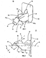
- FIGS. 1-4 illustrate a valve support member 10 for supporting a fluid discharge valve 21 ( FIG. 6 ).
- Valve support member 10 is configured for use with a urine collection bag assembly 100 ( FIG. 10 ) and includes a body 12 defining a fluid inlet 14 ( FIG. 4 ), a fluid outlet 16 ( FIG.1 ), and a fluid channel 18 extending between fluid inlet 14 and fluid outlet 16.
- Body 12 of valve support member 10 includes a base member 20 through which fluid inlet 14 extends, a central body portion 22 which defines a substantial portion of fluid channel 18 and a spout 24.
- Spout 24 defines the outlet end of fluid channel 18 including fluid outlet 16.
- Support member 10 can be monolithically constructed from a polymeric material or any other material having the requisite strength characteristic. Alternately, the components of support member 10 can be constructed from different materials and fastened together using any known fastening process, e.g., welding, adhesives, etc.
- base member 20 defines a flat, plate-like member which is configured to being sealingly attached to collection bag 102 as will be discussed in further detail below.
- central body portion 22 is substantially rectangular in shape and includes rounded top and bottom surfaces 22a and 22b and linear sidewalls 22c. Alternately, other body portion configurations are envisioned, e.g., square, cylindrical, oval, etc.
- Central body portion 22 defines a longitudinal axis "A" which is substantially parallel to a horizontal axis "H" when the collection bag is empty ( FIG. 2 ).
- Central body portion 22 has a first end 26 formed integrally with or fastened to base member 20 and a second end 28 spaced from base member 20.
- Spout 24 defines a second longitudinal axis "B” and is supported on second end 28 of central body portion 22.
- Spout 24 has a substantially cylindrical configuration although other configurations are envisioned.
- first and second longitudinal axis A and B define an angle ⁇ of between about 15° and about 75° and preferably between about 30° and about 60°. In one embodiment, ⁇ is about 45°.
- a fluid channel 18 extends through support member 10 from fluid inlet 14 ( FIG. 4 ) to fluid outlet 16.
- Angle ⁇ is chosen such that when collection bag 102 is filled with fluid and the outer wall of bag 102 bulges outwardly, the longitudinal axis ⁇ of spout 24 moves to a substantially vertical orientation.
- Support member 10 also includes a strut 32 which is supported on an upper surface of first end 26 of central portion 22 and includes a first edge fastened to central portion 22 and a second edge fastened to a front surface of base member 20.
- Strut 32 is substantially rigid and provides stability to support member 10.
- a fin 34 is supported on second end 28 of central portion 22.
- fin 34 includes a curved upper surface 34a and is configured to be positioned within discharge valve 21 to assist in securing discharge valve 21 to support member 10. Fin 34 and strut 32 are spaced on central body portion 22 to define a recess 36.
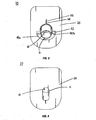
- a flange or support plate 40 is secured to second end 28 of central body portion 22 below spout 24.
- Support plate 40 includes first and second transverse extensions 40a and 40b defining an engagement surface 42.
- One end of plate 40 has a lip or overhang 41.
- Engagement surface 42 defines a plane which is substantially perpendicular to second longitudinal axis B.
- Transverse extensions 40a and 40b and engagement surface 42 in combination with fin 34 facilitate attachment of support member 10 to discharge valve 21 as will be discussed in detail below.
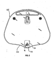
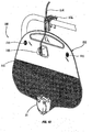
- collection bag assembly 100 includes collection bag 102 including discharge valve 21, a drain tube 104 and a support hangar 106.
- Collection bag 102 also can include an inlet or anti-reflux valve 108 and one or more vents 110. As illustrated, discharge valve 21 is supported adjacent a bottom portion of bag 102
- collection bag 102 is constructed from first and second sheets of flexible material which are sealed, e.g., welded, glued, etc. at their edges to define a fluid reservoir 112 ( FIG. 10 ).
- the first and second sheets of material may be constructed from polyvinyl chloride or other suitable flexible material.
- the bottom portion of collection bag 102 defines a gulley or well 114 which defines the lowest point of fluid reservoir 112.
- An opening (not shown) is formed in first sheet 116 of collection bag 102.
- Base member 20 of support member 10 is secured to first sheet 116 using any known fastening technique, e.g., heat sealing, adhesives, welding, etc., such that fluid inlet 14 ( FIG.
- a flexible discharge tube 117 is secured to spout 24 and extends through discharge valve 21. As such, fluid in collection bag 102 collects in the bottom of collection bag 102 and flows through the opening in front sheet 116 into fluid channel 18 of support member 10 and into discharge tube 117.
- discharge valve 21 has an outer housing 120 and a rotatable valve member 122 positioned within and defining a front surface of discharge valve 21.
- Valve member 122 is movable from a first position compressing flexible tube 117 to a second position wherein substantially no compression is applied to tube 117 and fluid can flow from tube 117.
- Discharge valve 21 is known in the art and is sold by Kendall under the trade name SPLASHGUARD II TM and will not be discussed in specific detail herein. Alternately, other valve types may be used in conjunction with the presently disclosed support member.
- Outer housing 120 of valve 21 includes a rear wall 124 which includes an opening 126 ( FIG. 8 ).
- opening 126 is substantially rectangular and includes a circular upper wall 128 and a pair of linear transverse slots 130.
- a series of small spaced protrusions 132 project inwardly from upper wall 128. Protrusions 132 cooperate with fin 34 to align support member 12 within valve 21.
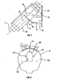
- Opening 126 is dimensioned to receive a distal portion of body 12 of support member 10. More specifically, the portion of body 12 of support member 10 including spout 24 and the distal portion of central body portion 22 is inserted through opening 126 into outer housing 120 of discharge valve 21. In this position, fin 34 of support member 10 is positioned within outer housing 122 and transverse extensions 40a and 40b of support plate 40 extend through transverse slots 130 of opening 126 such that engagement surface 42 rests on the portion of outer housing 120 defining slots 130. With discharge valve 21 supported on support member 10, discharge valve 21 defines a longitudinal axis "C" which is parallel to axis B defined by spout 24 of support member 10 and offset by angle ⁇ from axis A defined by the central body portion 22 of support member 10.
- spout 24 and discharge valve 21 move to a position in which rotatable valve member 122 is more easily accessible and fluid can be drained spill free from collection bag 102, i.e., spout 24 is moved to a vertical position in which fluid outlet 18 is able to drain straight downwardly.
Abstract
Description
- The present disclosure relates to fluid collection bags for receiving bodily fluids, e.g., urine. More specifically, the present disclosure relates to a collapsible urine collection bag including an angled support member for mounting a discharge valve thereon defining a fluid channel and having a spout The support member is configured to position the discharge valve and the spout are in a more accessible and proper orientation to effect spill free drainage of the bag when the bag is filled or partially filled with fluid.
- Fluid collection systems for collecting bodily fluids such as urine are well known in the art. Typically, urine collection systems include a urine collection bag defining a fluid reservoir and having an inlet port or ports for receiving fluid and a discharge port to facilitate drainage of the collection bag. A discharge tube is attached to the discharge port and a discharge valve is provided on or along the discharge tube to regulate fluid flow, e.g., drainage, from the collection bag.
- Generally, a fluid collection bag is formed from front and rear sheets of flexible material sealed together at their edges to define a fluid reservoir. A discharge port is positioned on a lower end of the front sheet of the collection bag with a discharge tube extending therefrom. In some known collection systems, a discharge valve is supported on the discharge tube or mounting structure supported on the bag at a location to regulate fluid flow through the discharge tube.
- In use, a urine collection bag is supported, e.g., hung, on support structure, e.g., a bed frame, located below a patient. A drain tube having one end connected to a catheterized patient and a second end in fluid communication with the urine collection bag directs urine to the urine collection bag. When the urine collection bag begins to fill, the front and rear sheets forming the collection bag expand outwardly. Since the lower end of the front and rear sheets are sealed together, the lower end of the front sheet of the collection bag expands such that the exterior surface of the collection bag defines a curved downwardly facing surface. This outward bulging of the front sheet of the collection bag, causes a discharge spout of the collection bag and the discharge valve to tilt inwardly. As a result, the discharge valve becomes less accessible and the discharge spout moves to skewed on non-vertical orientation to make spill free drainage of the collection bag.
- Accordingly, it would be desirable to provide a collection bag having mounting structure for the discharge valve which compensates for expansion of a fluid collection bag to facilitate rapid and spill free drainage of the fluid collection bag.
-
WO01/06969 - In accordance with the present invention there is provided a urine collection bag as defined in appended claim 1.
- In a preferred embodiment is between about 30°, and about 60°. In another preferred embodiment, is about 45°.
- In one embodiment, the support member includes a base portion defining an inlet opening and a central body portion. The fluid channel extends from the base portion through the central body portion to the spout. The central body portion defines a longitudinal axis which is substantially parallel to a horizontal axis when the fluid reservoir of the urine collection bag is empty. The base portion is a plate-like member which can be welded to the front sheet of flexible material.
- The urine collection bag further includes a discharge valve supported on the support member and a flexible discharge tube secured to the spout of the support member. The discharge valve includes a housing and a rotatable valve member. The rotatable valve member is movable from a closed position compressing the flexible discharge tube to an open position to permit fluid to flow through the discharge tube.
- Various embodiments of the presently disclosed fluid collection bag with angled valve support member are disclosed herein with reference to the drawings, wherein:
-
FIG. 1 is a perspective view of one embodiment of the presently disclosed valve support member of a fluid collection bag; -
FIG. 2 is a side view of the valve support member shown inFIG. 1 ; -
FIG. 3 is a front view of the valve support member shown inFIG. 1 ; -
FIG. 4 is a rear view of the valve support member shown inFIG. 1 ; -
FIG. 5 is a front view of a fluid collection bag having the valve support member shown inFIG. 1 secured thereto; -
FIG. 6 is a front view of the fluid collection bag shown inFIG. 5 with a discharge valve supported on the valve support member; -
FIG. 7 is a side perspective view of the fluid collection bag shown inFIG. 6 including a drain tube and hangar structure for securing the collection bag on a bed frame; and -
FIG. 8 is a side perspective view of the collection bag assembly shown inFIG. 7 with the collection bag partially filled with fluid. - Embodiments of the presently disclosed urine collection bag assembly with angled valve support member will now be described in detail with reference to the drawings wherein like reference numerals designate identical or corresponding elements in each of the several views.
-
FIGS. 1-4 illustrate avalve support member 10 for supporting a fluid discharge valve 21 (FIG. 6 ). Valvesupport member 10 is configured for use with a urine collection bag assembly 100 (FIG. 10 ) and includes abody 12 defining a fluid inlet 14 (FIG. 4 ), a fluid outlet 16 (FIG.1 ), and afluid channel 18 extending betweenfluid inlet 14 andfluid outlet 16.Body 12 ofvalve support member 10 includes abase member 20 through whichfluid inlet 14 extends, acentral body portion 22 which defines a substantial portion offluid channel 18 and aspout 24.Spout 24 defines the outlet end offluid channel 18 includingfluid outlet 16. -
Support member 10 can be monolithically constructed from a polymeric material or any other material having the requisite strength characteristic. Alternately, the components ofsupport member 10 can be constructed from different materials and fastened together using any known fastening process, e.g., welding, adhesives, etc. In one embodiment,base member 20 defines a flat, plate-like member which is configured to being sealingly attached tocollection bag 102 as will be discussed in further detail below. As shown inFIGS. 1 and 2 ,central body portion 22 is substantially rectangular in shape and includes rounded top and bottom surfaces 22a and 22b and linear sidewalls 22c. Alternately, other body portion configurations are envisioned, e.g., square, cylindrical, oval, etc.Central body portion 22 defines a longitudinal axis "A" which is substantially parallel to a horizontal axis "H" when the collection bag is empty (FIG. 2 ).Central body portion 22 has afirst end 26 formed integrally with or fastened tobase member 20 and asecond end 28 spaced frombase member 20.Spout 24 defines a second longitudinal axis "B" and is supported onsecond end 28 ofcentral body portion 22.Spout 24 has a substantially cylindrical configuration although other configurations are envisioned. In one embodiment, first and second longitudinal axis A and B define an angle β of between about 15° and about 75° and preferably between about 30° and about 60°. In one embodiment, β is about 45°. It is envisioned that other angles may be desirable outside of the ranges listed above, e.g., 10°, etc. As discussed above, afluid channel 18 extends throughsupport member 10 from fluid inlet 14 (FIG. 4 ) tofluid outlet 16. Angle β is chosen such that whencollection bag 102 is filled with fluid and the outer wall ofbag 102 bulges outwardly, the longitudinal axis β ofspout 24 moves to a substantially vertical orientation. -
Support member 10 also includes astrut 32 which is supported on an upper surface offirst end 26 ofcentral portion 22 and includes a first edge fastened tocentral portion 22 and a second edge fastened to a front surface ofbase member 20.Strut 32 is substantially rigid and provides stability to supportmember 10. Afin 34 is supported onsecond end 28 ofcentral portion 22. In one embodiment,fin 34 includes a curved upper surface 34a and is configured to be positioned withindischarge valve 21 to assist in securingdischarge valve 21 to supportmember 10.Fin 34 and strut 32 are spaced oncentral body portion 22 to define a recess 36. - A flange or
support plate 40 is secured tosecond end 28 ofcentral body portion 22 belowspout 24.Support plate 40 includes first and secondtransverse extensions engagement surface 42. One end ofplate 40 has a lip oroverhang 41.Engagement surface 42 defines a plane which is substantially perpendicular to second longitudinal axisB. Transverse extensions engagement surface 42 in combination withfin 34 facilitate attachment ofsupport member 10 to dischargevalve 21 as will be discussed in detail below. - Referring briefly to
FIG. 10 ,collection bag assembly 100 includescollection bag 102 includingdischarge valve 21, adrain tube 104 and asupport hangar 106.Collection bag 102 also can include an inlet oranti-reflux valve 108 and one ormore vents 110. As illustrated,discharge valve 21 is supported adjacent a bottom portion ofbag 102 - Referring to
FIGS. 5 and10 ,collection bag 102 is constructed from first and second sheets of flexible material which are sealed, e.g., welded, glued, etc. at their edges to define a fluid reservoir 112 (FIG. 10 ). The first and second sheets of material may be constructed from polyvinyl chloride or other suitable flexible material. The bottom portion ofcollection bag 102 defines a gulley or well 114 which defines the lowest point offluid reservoir 112. An opening (not shown) is formed in first sheet 116 ofcollection bag 102.Base member 20 ofsupport member 10 is secured to first sheet 116 using any known fastening technique, e.g., heat sealing, adhesives, welding, etc., such that fluid inlet 14 (FIG. 4 ) is in fluid communication with the opening in front sheet 116 ofcollection bag 102 andcentral portion 22 ofsupport member 10 projects outwardly from front sheet 116 ofcollection bag 102. A flexible discharge tube 117 is secured to spout 24 and extends throughdischarge valve 21. As such, fluid incollection bag 102 collects in the bottom ofcollection bag 102 and flows through the opening in front sheet 116 intofluid channel 18 ofsupport member 10 and into discharge tube 117. - Referring to
FIGS. 6-8 ,discharge valve 21 has anouter housing 120 and arotatable valve member 122 positioned within and defining a front surface ofdischarge valve 21.Valve member 122 is movable from a first position compressing flexible tube 117 to a second position wherein substantially no compression is applied to tube 117 and fluid can flow from tube 117.Discharge valve 21 is known in the art and is sold by Kendall under the trade name SPLASHGUARD II™ and will not be discussed in specific detail herein. Alternately, other valve types may be used in conjunction with the presently disclosed support member.Outer housing 120 ofvalve 21 includes arear wall 124 which includes an opening 126 (FIG. 8 ). In one embodiment, opening 126 is substantially rectangular and includes a circularupper wall 128 and a pair of lineartransverse slots 130. A series of small spacedprotrusions 132 project inwardly fromupper wall 128.Protrusions 132 cooperate withfin 34 to alignsupport member 12 withinvalve 21. -
Opening 126 is dimensioned to receive a distal portion ofbody 12 ofsupport member 10. More specifically, the portion ofbody 12 ofsupport member 10 includingspout 24 and the distal portion ofcentral body portion 22 is inserted throughopening 126 intoouter housing 120 ofdischarge valve 21. In this position,fin 34 ofsupport member 10 is positioned withinouter housing 122 andtransverse extensions support plate 40 extend throughtransverse slots 130 of opening 126 such thatengagement surface 42 rests on the portion ofouter housing 120 definingslots 130. Withdischarge valve 21 supported onsupport member 10,discharge valve 21 defines a longitudinal axis "C" which is parallel to axis B defined byspout 24 ofsupport member 10 and offset by angle β from axis A defined by thecentral body portion 22 ofsupport member 10. - As illustrated in
FIGS. 6 ,7 and9 ,base member 20 ofsupport member 10 is secured to front sheet 116 ofcollection bag 102 anddischarge valve 21 is supported onsupport member 10. Thus, whencollection bag 102 is in its non-expanded or empty configuration, longitudinal axis B of spout 24 (FIG. 2 ) and longitudinal axis C of discharge valve 21 (FTG. 7) are tilted upwardly at an angle from a horizontal axis or plane defined by front sheet 116 ofcollection bag 102. Ascollection bag 102 fills with fluid and front sheet 116 bulges outwardly, longitudinal axis B ofspout 24 and longitudinal axis C ofdischarge valve 21 rotate back towards a vertical position (FIG. 9 ). Thus, ascollection bag 102 fills andcollection bag 102 bulges outwardly, spout 24 anddischarge valve 21 move to a position in whichrotatable valve member 122 is more easily accessible and fluid can be drained spill free fromcollection bag 102, i.e., spout 24 is moved to a vertical position in whichfluid outlet 18 is able to drain straight downwardly. - It will be understood that various modifications may be made to the embodiments disclosed herein. For example, it is envisioned that the configuration of the support member may be altered in many respects to support a variety of different valve configurations. Such is considered within the scope of this disclosure so long as the configuration of the support member is selected to compensate for outward bulging of the urine collection bag. Further, the present disclosure may be incorporated into collection bags in other surgical and non-surgical areas. Therefore, the above description should not be construed as limiting, but merely as exemplifications of preferred embodiments.
Claims (10)
- A urine collection bag (100) comprising:a first sheet of flexible material (116) and a second sheet of flexible material secured together to define a fluid reservoir (112), the first sheet of flexible material defining an opening to facilitate drainage of the reservoir; anda support member (10) defining a fluid channel (18) and including a spout (24) defining a longitudinal axis (B) and a fluid outlet (16), the support member (10) being secured to the first sheet of flexible material (116) such that the fluid channel (18) is in fluid communication with the opening in the first sheet of flexible material;characterised in that the support member (10) is configured such that the longitudinal axis (B) of the spout (24) and a longitudinal axis (A) of the central body portion (22) define an angle β, wherein β is between about 15° and about 75°.
- A urine collection bag (100) according to Claim 1, wherein β is between about 30° and about 60°.
- A urine collection bag (100) according to Claim 2, wherein β is about 45°.
- A urine collection bag (100) according to Claim 1, wherein the support member (10) further includes a base portion (20) defming an inlet opening (14) and a central body portion (22), the fluid channel (18) extending from the base portion (20) through the central body portion (22) to the spout (24).
- A urine collection bag (100) according to Claim 4, wherein the urine collection bag (100) further includes a discharge valve (21) supported on the support member (10).
- A urine collection bag (100) according to Claim 5, further including a flexible discharge tube (117) secured to the spout (24) of the support member (10).
- A urine collection bag (100) according to Claim 6, wherein the discharge valve (21) includes a housing (120) and a rotatable valve member (122), the rotatable valve member (122) being movable from a closed position compressing the flexible discharge tube (117) to an open position to permit fluid to flow through the discharge tube (117).
- A urine collection bag (100) according to Claim 4, wherein the base portion (20) is a plate-like member.
- A urine collection bag (100) according to Claim 5, wherein the base portion (20) is welded to the front sheet of flexible material (116).
- A urine collection bag (100) according to Claim 5, wherein the longitudinal axis (A) of the central body portion (22) in use is substantially parallel to a horizontal axis (H) when the fluid reservoir (112) of the urine collection bag (100) is empty.
Applications Claiming Priority (1)
| Application Number | Priority Date | Filing Date | Title |
|---|---|---|---|
| US11/362,658 US7462171B2 (en) | 2006-02-24 | 2006-02-24 | Urine collection bag with angled valve support |
Publications (2)
| Publication Number | Publication Date |
|---|---|
| EP1825837A1 EP1825837A1 (en) | 2007-08-29 |
| EP1825837B1 true EP1825837B1 (en) | 2010-05-19 |
Family
ID=38141174
Family Applications (1)
| Application Number | Title | Priority Date | Filing Date |
|---|---|---|---|
| EP07250782A Active EP1825837B1 (en) | 2006-02-24 | 2007-02-23 | Urine collection bag with angled valve support |
Country Status (15)
| Country | Link |
|---|---|
| US (1) | US7462171B2 (en) |
| EP (1) | EP1825837B1 (en) |
| JP (1) | JP5081470B2 (en) |
| KR (1) | KR20070088401A (en) |
| CN (1) | CN101040820B (en) |
| AT (1) | ATE468092T1 (en) |
| AU (1) | AU2007200818B2 (en) |
| BR (1) | BRPI0700622A (en) |
| CA (1) | CA2579897C (en) |
| DE (1) | DE602007006568D1 (en) |
| ES (1) | ES2346253T3 (en) |
| MX (1) | MX2007002228A (en) |
| NZ (1) | NZ553442A (en) |
| SG (1) | SG135141A1 (en) |
| TW (1) | TW200806277A (en) |
Families Citing this family (9)
| Publication number | Priority date | Publication date | Assignee | Title |
|---|---|---|---|---|
| US8357105B2 (en) | 2008-08-07 | 2013-01-22 | Covidien Lp | Anti-reflux mechanism for urine collection systems |
| TWI491388B (en) * | 2009-10-09 | 2015-07-11 | Kevin Yang | Carrying bag |
| US9668909B1 (en) * | 2011-02-27 | 2017-06-06 | Ann M. Lormand-Koch | Method of using gastrojejunostomy drainage bag |
| CN102866402B (en) | 2012-08-22 | 2014-12-10 | 深圳市福锐达科技有限公司 | Wireless fidelity (WIFI)-based wireless hydrological regime detection system and method |
| US9408378B2 (en) * | 2014-05-30 | 2016-08-09 | Vexilar, Inc. | Fish finder device housing and system |
| CN105148338B (en) * | 2015-07-31 | 2020-12-11 | 山东朱氏药业集团有限公司 | Connecting drainage bag |
| CN109963533A (en) * | 2016-09-14 | 2019-07-02 | 科疗有限公司 | Method and bag container for drained of urine bag |
| US11540962B2 (en) * | 2018-11-16 | 2023-01-03 | Donna Weaver | Product bag retention assembly |
| CN113713128A (en) * | 2021-08-17 | 2021-11-30 | 苏州宝凡电子科技有限公司 | Block chain marking system for distributed storage data |
Family Cites Families (146)
| Publication number | Priority date | Publication date | Assignee | Title |
|---|---|---|---|---|
| US693127A (en) * | 1901-10-04 | 1902-02-11 | Paul H Gardner | Adjustable bracket. |
| US1951196A (en) * | 1933-07-19 | 1934-03-13 | Meadows Amos | Adjustable bedspring rest |
| US2630303A (en) * | 1949-12-05 | 1953-03-03 | Charles F Krucker | Cheese stirrer |
| US3312221A (en) * | 1963-10-25 | 1967-04-04 | Alfred P H Overment | Urinary drainage apparatus |
| US3259920A (en) | 1963-11-06 | 1966-07-12 | Ronald L Voller | Sanitary fluid receptacle |
| US3534738A (en) | 1964-10-13 | 1970-10-20 | Charles M Huck | Bedside and ambulatory portable drainage system |
| US3537455A (en) | 1967-06-08 | 1970-11-03 | Baxter Laboratories Inc | Drainage apparatus |
| US3537109A (en) | 1968-04-15 | 1970-11-03 | American Hospital Supply Corp | Hanger structure for medical liquid collection container |
| US3529599A (en) | 1968-05-08 | 1970-09-22 | American Hospital Supply Corp | Collection container for medical liquids |
| US3601119A (en) | 1968-12-23 | 1971-08-24 | Horizon Ind Ltd | Body fluid drainage apparatus |
| US3583401A (en) * | 1969-01-21 | 1971-06-08 | Bard Inc C R | Vented closed drainage system with double lumen tube |
| US3661143A (en) * | 1969-06-23 | 1972-05-09 | Henkin Melvyn Lane | Medical apparatus for drainage, collection and monitoring of body fluids |
| US3661153A (en) * | 1970-03-27 | 1972-05-09 | Packaging Associates Inc | Body fluid drainage bag |
| US3699964A (en) | 1970-07-02 | 1972-10-24 | Bard Inc C R | Closed urinary drainage and irrigation system |
| US3820546A (en) * | 1970-08-26 | 1974-06-28 | Abbott Lab | Combined air vent,filter and adapter for urinary drainage assemblies |
| US3683894A (en) | 1970-09-21 | 1972-08-15 | Kendall & Co | Urine meter and drainage receptacles |
| US3650272A (en) * | 1970-09-25 | 1972-03-21 | Bard Inc C R | Drainage bag |
| US3800795A (en) * | 1971-06-16 | 1974-04-02 | Sherwood Medical Ind Inc | Urinary drainage collecting device |
| US3716055A (en) * | 1971-08-02 | 1973-02-13 | Plastronics Inc | Support apparatus for a bedside drainage bag |
| US3831453A (en) | 1972-02-10 | 1974-08-27 | Kendall & Co | Urine meter and collection receptacle |
| GB1387107A (en) | 1972-02-25 | 1975-03-12 | Pharma Plast Australia Pty Ltd | Body-fluid collecting apparatus |
| DE7211842U (en) * | 1972-03-28 | 1972-08-24 | Fresenius E Kg | UROMETER |
| US3776231A (en) | 1972-05-22 | 1973-12-04 | Medical Dev Corp | Urinary drainage apparatus |
| US3896718A (en) | 1972-06-30 | 1975-07-29 | Joseph Giambalvo | Shelf arrangement and bracket therefor |
| US3906930A (en) | 1973-03-23 | 1975-09-23 | Dr Luis A Guerra | Blood taking device |
| US4002075A (en) * | 1973-07-11 | 1977-01-11 | Smiths Industries Limited | Liquid-measuring apparatus |
| US3961529A (en) * | 1973-08-09 | 1976-06-08 | International Paper Company | Urine metering and collection system |
| US4000649A (en) * | 1973-08-09 | 1977-01-04 | International Paper Company | Urine metering and collection system |
| US3952729A (en) * | 1974-08-29 | 1976-04-27 | The Kendall Company | Diagnostic device for a liquid sample |
| AR205591A1 (en) * | 1974-11-15 | 1976-05-14 | Kendall & Co | DEVICE FOR MEASURING AND COLLECTING A URINE DISCHARGE |
| US3943929A (en) * | 1974-11-15 | 1976-03-16 | The Kendall Company | Multi-chamber container and method |
| US4095589A (en) * | 1975-05-20 | 1978-06-20 | Plastronics, Inc. | Combination urine meter and drainage receptacle |
| US4013064A (en) * | 1975-06-26 | 1977-03-22 | The Kendall Company | Port means for a liquid transport system |
| US4027842A (en) * | 1975-09-24 | 1977-06-07 | Baxter Travenol Laboratories, Inc. | Flexible hanger member for drainage bags and the like |
| US4014322A (en) * | 1975-10-23 | 1977-03-29 | The Kendall Company | Specimen collecting device and method |
| US4015605A (en) * | 1975-10-28 | 1977-04-05 | The Kendall Company | Drainage receptacle |
| US4019707A (en) * | 1975-10-30 | 1977-04-26 | Will Ross, Inc. | Device for supporting fluid receptacles |
| US4564361A (en) * | 1975-11-18 | 1986-01-14 | Hiroshi Akiyama | Catheter |
| US4105500A (en) | 1975-11-21 | 1978-08-08 | The Kendall Company | Diagnostic device for a liquid sample and method |
| US4085755A (en) * | 1976-04-29 | 1978-04-25 | Benjamin Stuart Burrage | Urinary drainage bag |
| US4055187A (en) | 1976-08-05 | 1977-10-25 | The Kendall Company | Catheter with improved balloon assembly |
| US4109837A (en) | 1976-12-22 | 1978-08-29 | The Kendall Company | Liquid sampling device |
| US4106675A (en) | 1976-12-22 | 1978-08-15 | The Kendall Company | Liquid sampling device |
| US4192295A (en) * | 1977-05-02 | 1980-03-11 | M.U. Engineering & Mfg. Co. | Bedside drainage bag |
| US4100802A (en) | 1977-06-08 | 1978-07-18 | The Kendall Company | Liquid measuring device |
| US4529398A (en) | 1977-06-09 | 1985-07-16 | Wong Patrick S | Method for preventing contamination of catheter and drainage receptacle |
| US4131016A (en) | 1977-11-09 | 1978-12-26 | The Kendall Company | Peak flow measuring device |
| US4178934A (en) | 1977-12-27 | 1979-12-18 | G. D. Searle & Co. | Urine meter and collection assembly |
| US4187722A (en) * | 1978-03-22 | 1980-02-12 | The Kendall Company | Device for measuring the velocity of a urine discharge |
| US4200112A (en) * | 1978-07-12 | 1980-04-29 | The Kendall Company | Device for measuring the force of a urine discharge |
| US4254771A (en) * | 1978-08-25 | 1981-03-10 | American Hospital Supply Corporation | Folded top urine bag with elongated stiffening panel |
| US4219177A (en) | 1978-08-25 | 1980-08-26 | American Hospital Supply Corporation | Bed rail hanger system |
| US4189789A (en) * | 1978-08-25 | 1980-02-26 | American Hospital Supply Corporation | Urine collection container with coupling for suspension line |
| US4176412A (en) | 1978-09-15 | 1979-12-04 | The Kendall Company | Urine collection device |
| US4313447A (en) * | 1979-01-22 | 1982-02-02 | The Kendall Company | Collection bag |
| US4265243A (en) * | 1979-04-04 | 1981-05-05 | The Kendall Company | Collection container with siphon assembly |
| US4238448A (en) | 1979-04-24 | 1980-12-09 | The Kendall Company | Discharge measuring device |
| US4241017A (en) | 1979-04-24 | 1980-12-23 | The Kendall Company | Device for measuring a urine discharge |
| US4317550A (en) * | 1979-09-17 | 1982-03-02 | Baxter Travenol Laboratories, Inc. | Apparatus for suspending a drainage bag |
| US4280498A (en) | 1979-10-22 | 1981-07-28 | Hollister Incorporated | Valved drain assembly for urostomy pouch |
| US4305290A (en) | 1979-12-06 | 1981-12-15 | The Kendall Company | Urine meter |
| US4312351A (en) * | 1979-12-26 | 1982-01-26 | Kurtz Leonard D | Drainage device with separate outflow chamber |
| US4312352A (en) * | 1980-01-29 | 1982-01-26 | C. R. Bard, Inc. | Hanger, hook and handle assembly for urinary drainage bag |
| US4384485A (en) * | 1980-02-11 | 1983-05-24 | The Kendall Company | Device for indicating liquid level |
| US4305405A (en) | 1980-03-25 | 1981-12-15 | C. R. Bard, Inc. | Urine meter bag |
| US4452253A (en) * | 1980-04-04 | 1984-06-05 | The Kendall Company | Collection bag |
| US4333480A (en) * | 1980-04-11 | 1982-06-08 | The Kendall Company | Urine receptacle with a tubular section to retain an antimicrobial agent |
| US4305403A (en) | 1980-04-11 | 1981-12-15 | The Kendall Company | Urine receptor |
| US4372313A (en) * | 1980-04-11 | 1983-02-08 | The Kendall Company | Body drainage receptacle with anti-septic catheter contact surface in receiving pocket |
| US4301813A (en) | 1980-04-11 | 1981-11-24 | The Kendall Company | Urine meter |
| US4305404A (en) | 1980-04-11 | 1981-12-15 | The Kendall Company | Urine meter |
| US4465484A (en) | 1980-05-14 | 1984-08-14 | The Kendall Company | Collection device for body fluids |
| US4386930A (en) * | 1980-05-14 | 1983-06-07 | The Kendall Company | Collection device for body fluids with antiseptic pump |
| US4738671A (en) * | 1980-06-06 | 1988-04-19 | C. R. Bard, Inc. | Chest drainage apparatus with check valve |
| US4332252A (en) * | 1980-07-11 | 1982-06-01 | The Kendall Company | Drainage receptacle with support member |
| US4366836A (en) * | 1980-09-17 | 1983-01-04 | The Kendall Company | Valved vent for a liquid drainage system |
| US4328828A (en) * | 1980-09-17 | 1982-05-11 | The Kendall Company | Drainage system with vent |
| US4483688A (en) | 1980-09-22 | 1984-11-20 | Hiroshi Akiyama | Catheter |
| US4344432A (en) | 1981-01-07 | 1982-08-17 | The Kendall Company | Device for collecting body fluids |
| US4334537A (en) * | 1981-01-28 | 1982-06-15 | The Kendall Company | Drainage receptacle with anti-reflux valve |
| US4465479A (en) | 1981-03-13 | 1984-08-14 | C. R. Bard, Inc. | Air vent splash guard for drip chamber |
| US4447939A (en) * | 1981-03-25 | 1984-05-15 | The Kendall Company | Device for collecting body liquids |
| US4393880A (en) | 1981-03-25 | 1983-07-19 | The Kendall Company | Device for collecting body liquids |
| US4421509A (en) | 1981-06-15 | 1983-12-20 | Hollister Incorporated | Leg bag for urinary incontinence |
| US4462510A (en) | 1981-06-30 | 1984-07-31 | Kingsdown Medical Consultants Limited | Tap for drainage bag |
| GB2104044B (en) * | 1981-08-07 | 1985-08-21 | Craig Med Prod Ltd | Bag and valve assembley for medical use |
| DE3131378A1 (en) | 1981-08-07 | 1983-02-24 | B. Braun Melsungen Ag, 3508 Melsungen | SECRET COLLECTING DEVICE |
| US4417891A (en) | 1981-10-08 | 1983-11-29 | The Kendall Company | Collection device with antiseptic liquid for body fluids |
| US4436024A (en) * | 1981-12-24 | 1984-03-13 | Arden Terry D | Fireplace rotisserie |
| US4417892A (en) | 1981-12-31 | 1983-11-29 | C. R. Bard, Inc. | Urine drainage bag outlet tube and method for eliminating or reducing migration of bacteria |
| US4449969A (en) * | 1982-02-03 | 1984-05-22 | The Kendall Company | Drainage receptacle with support frame |
| GB2118525A (en) | 1982-04-16 | 1983-11-02 | Craig Med Prod Ltd | Drainage bag and support therefor |
| US4460362A (en) | 1982-07-21 | 1984-07-17 | The Kendall Company | Drainage system with holding chamber |
| US4503864A (en) * | 1982-09-30 | 1985-03-12 | Powers Jerry G | Urine specimen collection apparatus with a separable compartment |
| US4511358A (en) * | 1982-09-30 | 1985-04-16 | Johnson Jr Clifford B | Urine bag carrier with a stretchable front panel |
| US4526576A (en) | 1983-01-27 | 1985-07-02 | The Kendall Company | Liquid drainage system with interlocked handle |
| US4512770A (en) * | 1983-01-27 | 1985-04-23 | The Kendall Company | Liquid drainage system with anti-reflux valve |
| US4511357A (en) * | 1983-02-09 | 1985-04-16 | The Kendall Company | Liquid drainage system with a guidable valve element |
| US4521213A (en) * | 1983-02-10 | 1985-06-04 | The Kendall Company | Liquid drainage system with hinged cup-shaped valve |
| US4490144A (en) | 1983-02-10 | 1984-12-25 | The Kendall Company | Urine drainage receptacle with a normally open reflux valve |
| US4501584A (en) * | 1983-03-04 | 1985-02-26 | The Kendall Company | Liquid drainage system with formed hinged support sheet |
| US4579126A (en) * | 1983-03-04 | 1986-04-01 | The Kendall Company | Liquid drainage system with emptying system |
| US4658834A (en) * | 1983-03-16 | 1987-04-21 | C.R. Bard, Inc. | Medical apparatus for monitoring body liquid discharge |
| US4450936A (en) * | 1983-05-18 | 1984-05-29 | Interlake, Inc. | Removable step for pallet rack |
| DK149402C (en) * | 1983-05-27 | 1986-11-10 | Coloplast As | CONTAINER FOR COLLECTION OF URINE AND / OR FAECALS |
| US4650478A (en) * | 1983-06-28 | 1987-03-17 | The Kendall Company | Liquid drainage system having a hook support member |
| US4562984A (en) * | 1983-08-08 | 1986-01-07 | Sherwood Medical Company | Drainage bag support |
| NL8304124A (en) * | 1983-12-01 | 1985-07-01 | Rechsteiner Jim | URINE COLLECTION BAG. |
| GB8402455D0 (en) * | 1984-01-31 | 1984-03-07 | Simpla Plastics | Urine collection |
| US4642105A (en) * | 1984-02-21 | 1987-02-10 | Toter Kimberly A M | Gastric drainage system |
| US4659329A (en) * | 1984-07-27 | 1987-04-21 | The Kendall Company | Liquid drainage system |
| US4573983A (en) * | 1984-07-27 | 1986-03-04 | The Kendall Company | Liquid collection system having an anti-septic member on the discharge section |
| US4633887A (en) * | 1984-08-03 | 1987-01-06 | Sherwood Medical Company | Anti-reflux drain tube and drainage meter combination |
| US4723950A (en) * | 1984-12-12 | 1988-02-09 | C. R. Bard, Inc. | Urine drainage bag outlet with barrier against microbial infection |
| US4640128A (en) * | 1984-12-20 | 1987-02-03 | The Kendall Company | Mechanism for proper alignment of sensor probes with fluid sample chamber |
| US4743236A (en) * | 1985-05-17 | 1988-05-10 | Plastronics, Inc. | Combination urine meter and urinary drainage bag and the method of use |
| US4660802A (en) * | 1985-11-08 | 1987-04-28 | Rao Medical Devices, Inc. | Liquid flow control device |
| US4745929A (en) * | 1985-12-27 | 1988-05-24 | The Kendall Company | Liquid drainage system with light emitters and detectors |
| US4723944A (en) * | 1986-06-05 | 1988-02-09 | Jensen Ole R | Fluid collection receptacle with improved non-return valve |
| US4731062A (en) * | 1986-06-20 | 1988-03-15 | The Kendall Company | Urine meter |
| US5300050A (en) * | 1986-10-07 | 1994-04-05 | Deknatel Technology Corporation | Drainage device |
| US4728324A (en) * | 1986-10-15 | 1988-03-01 | The Kendall Company | Urine meter valve with tamper indicator |
| US4815477A (en) * | 1986-10-15 | 1989-03-28 | The Kendall Company | Urine meter drain container with large and small sample ports |
| US5116139A (en) * | 1989-09-08 | 1992-05-26 | American Innotex, Inc. | Fluid containment bag |
| GB2202032B (en) * | 1987-03-09 | 1990-09-26 | Craig Med Prod Ltd | Tap for drainage bag |
| US4804376A (en) * | 1987-11-30 | 1989-02-14 | The Kendall Company | Annular reflux indicator for a urine collection bag |
| US4913161A (en) * | 1987-12-23 | 1990-04-03 | The Kendall Company | Bag-tilt indicator on urine bag |
| US4911697A (en) * | 1988-08-02 | 1990-03-27 | Sherwood Medical Company | Chest drainage unit having increased airflow capacity with capability to dampon noise |
| DE3931659A1 (en) * | 1988-10-12 | 1990-04-19 | Martin Rahe | DEVICE FOR RECORDING UNCONTROLLABLE ELIMINATED URINS |
| US5098418A (en) * | 1989-08-24 | 1992-03-24 | Maitz Carlos A | Aspirator device for body fluids |
| US5176665A (en) * | 1991-01-18 | 1993-01-05 | Alza Corporation | Antimicrobial device for urine drainage container |
| US5207661A (en) * | 1991-06-07 | 1993-05-04 | Smiths Industries Public Limited Company | Body fluid drainage assembly |
| US5211642A (en) * | 1991-10-28 | 1993-05-18 | Clendenning Beverly F | Chambers drainage system |
| CN2127007Y (en) * | 1992-03-20 | 1993-02-17 | 沈鹏里 | Urine-collecting bag |
| US5409014A (en) * | 1993-08-13 | 1995-04-25 | Dravon Medical, Inc. | Fluid meter |
| US5417657A (en) * | 1993-10-06 | 1995-05-23 | Hauer; Carolyn | No-sepsis urinary drainage catheter |
| US5725515A (en) * | 1994-11-01 | 1998-03-10 | Tri-State Hospital Supply Corporation | Urine sampling and bladder drainage system |
| US5891051A (en) * | 1995-06-02 | 1999-04-06 | C.R. Bard, Inc. | Electronic urine monitor |
| US5616138A (en) * | 1995-08-29 | 1997-04-01 | Tri State Hospital Supply Corporation | Urine drainage and collection device |
| US5989234A (en) * | 1997-01-14 | 1999-11-23 | Deknatel Technology Corporation | Device and system for draining a body cavity and methods related thereto |
| GB2325510B (en) * | 1997-05-21 | 1999-04-28 | Bristol Myers Squibb Co | A tap for a drainage bag, and a method of assembly |
| US6736803B2 (en) * | 1999-01-13 | 2004-05-18 | Cawood Family Limited Partnership | Urine bag and self-retracting drain tube therefor |
| US6210383B1 (en) * | 1999-01-29 | 2001-04-03 | Atrium Medical Corporation | Fluid recovery system |
| US6551292B1 (en) * | 1999-06-28 | 2003-04-22 | The Procter & Gamble Company | Shaped flange for a urine collector |
| US6709420B1 (en) * | 1999-07-21 | 2004-03-23 | C.R. Bard, Inc. | Switch-style drain assembly for urine collection container |
| JP3732099B2 (en) * | 2001-03-01 | 2006-01-05 | 住友ベークライト株式会社 | Urine weighing bag |
-
2006
- 2006-02-24 US US11/362,658 patent/US7462171B2/en active Active
-
2007
- 2007-02-23 ES ES07250782T patent/ES2346253T3/en active Active
- 2007-02-23 AT AT07250782T patent/ATE468092T1/en not_active IP Right Cessation
- 2007-02-23 JP JP2007044728A patent/JP5081470B2/en active Active
- 2007-02-23 DE DE602007006568T patent/DE602007006568D1/en active Active
- 2007-02-23 SG SG200701294-1A patent/SG135141A1/en unknown
- 2007-02-23 AU AU2007200818A patent/AU2007200818B2/en active Active
- 2007-02-23 CA CA2579897A patent/CA2579897C/en active Active
- 2007-02-23 EP EP07250782A patent/EP1825837B1/en active Active
- 2007-02-23 MX MX2007002228A patent/MX2007002228A/en active IP Right Grant
- 2007-02-25 CN CN2007101035493A patent/CN101040820B/en active Active
- 2007-02-26 TW TW096106534A patent/TW200806277A/en unknown
- 2007-02-26 KR KR1020070018946A patent/KR20070088401A/en not_active Application Discontinuation
- 2007-02-26 NZ NZ553442A patent/NZ553442A/en not_active IP Right Cessation
- 2007-02-26 BR BRPI0700622-5A patent/BRPI0700622A/en not_active IP Right Cessation
Also Published As
| Publication number | Publication date |
|---|---|
| JP2007222639A (en) | 2007-09-06 |
| CN101040820A (en) | 2007-09-26 |
| DE602007006568D1 (en) | 2010-07-01 |
| TW200806277A (en) | 2008-02-01 |
| AU2007200818B2 (en) | 2011-10-27 |
| MX2007002228A (en) | 2008-11-19 |
| ATE468092T1 (en) | 2010-06-15 |
| EP1825837A1 (en) | 2007-08-29 |
| BRPI0700622A (en) | 2007-11-06 |
| US7462171B2 (en) | 2008-12-09 |
| AU2007200818A1 (en) | 2007-09-13 |
| SG135141A1 (en) | 2007-09-28 |
| ES2346253T3 (en) | 2010-10-13 |
| CA2579897A1 (en) | 2007-08-24 |
| CN101040820B (en) | 2012-03-21 |
| NZ553442A (en) | 2008-10-31 |
| CA2579897C (en) | 2015-01-20 |
| JP5081470B2 (en) | 2012-11-28 |
| KR20070088401A (en) | 2007-08-29 |
| US20070203465A1 (en) | 2007-08-30 |
Similar Documents
| Publication | Publication Date | Title |
|---|---|---|
| EP1825837B1 (en) | Urine collection bag with angled valve support | |
| EP1825838A1 (en) | Urine collection bag with integral anti-reflux valve | |
| EP0645151B1 (en) | A container for blood | |
| US10098990B2 (en) | Drainage container device and suction bag unit | |
| AU1166188A (en) | Auto transfusion device | |
| CA2458755A1 (en) | An ostomy appliance | |
| WO1999066859A3 (en) | A collecting bag for human body wastes | |
| EP0286229A1 (en) | Tap for drainage bag | |
| US20090030384A1 (en) | Fastening Device for a Drainage Container | |
| US6800072B2 (en) | Contrast dispensing system | |
| US4493701A (en) | Wound drainage device of resilient sidewalls with a constant rate of recovery | |
| CN105873833B (en) | Container cover and valve | |
| AU2005237267A1 (en) | An ostomy appliance | |
| US5970979A (en) | Device and method for maintaining an open pouch structure | |
| EP4037623B1 (en) | Ostomy appliance | |
| GB2615827A (en) | An ostomy appliance | |
| JP2006271436A (en) | Medical instrument | |
| EP0830904A2 (en) | Paint system pressure device | |
| JP2007529244A (en) | Drainage bag | |
| AU2022381849A1 (en) | A waste collection bag |
Legal Events
| Date | Code | Title | Description |
|---|---|---|---|
| PUAI | Public reference made under article 153(3) epc to a published international application that has entered the european phase |
Free format text: ORIGINAL CODE: 0009012 |
|
| AK | Designated contracting states |
Kind code of ref document: A1 Designated state(s): AT BE BG CH CY CZ DE DK EE ES FI FR GB GR HU IE IS IT LI LT LU LV MC NL PL PT RO SE SI SK TR |
|
| AX | Request for extension of the european patent |
Extension state: AL BA HR MK YU |
|
| 17P | Request for examination filed |
Effective date: 20080201 |
|
| 17Q | First examination report despatched |
Effective date: 20080311 |
|
| REG | Reference to a national code |
Ref country code: HK Ref legal event code: DE Ref document number: 1107756 Country of ref document: HK |
|
| AKX | Designation fees paid |
Designated state(s): AT BE BG CH CY CZ DE DK EE ES FI FR GB GR HU IE IS IT LI LT LU LV MC NL PL PT RO SE SI SK TR |
|
| GRAP | Despatch of communication of intention to grant a patent |
Free format text: ORIGINAL CODE: EPIDOSNIGR1 |
|
| GRAS | Grant fee paid |
Free format text: ORIGINAL CODE: EPIDOSNIGR3 |
|
| GRAA | (expected) grant |
Free format text: ORIGINAL CODE: 0009210 |
|
| AK | Designated contracting states |
Kind code of ref document: B1 Designated state(s): AT BE BG CH CY CZ DE DK EE ES FI FR GB GR HU IE IS IT LI LT LU LV MC NL PL PT RO SE SI SK TR |
|
| REG | Reference to a national code |
Ref country code: GB Ref legal event code: FG4D |
|
| REG | Reference to a national code |
Ref country code: CH Ref legal event code: EP |
|
| REG | Reference to a national code |
Ref country code: IE Ref legal event code: FG4D |
|
| REF | Corresponds to: |
Ref document number: 602007006568 Country of ref document: DE Date of ref document: 20100701 Kind code of ref document: P |
|
| REG | Reference to a national code |
Ref country code: NL Ref legal event code: VDEP Effective date: 20100519 |
|
| REG | Reference to a national code |
Ref country code: ES Ref legal event code: FG2A Ref document number: 2346253 Country of ref document: ES Kind code of ref document: T3 |
|
| LTIE | Lt: invalidation of european patent or patent extension |
Effective date: 20100519 |
|
| PG25 | Lapsed in a contracting state [announced via postgrant information from national office to epo] |
Ref country code: SE Free format text: LAPSE BECAUSE OF FAILURE TO SUBMIT A TRANSLATION OF THE DESCRIPTION OR TO PAY THE FEE WITHIN THE PRESCRIBED TIME-LIMIT Effective date: 20100519 Ref country code: LT Free format text: LAPSE BECAUSE OF FAILURE TO SUBMIT A TRANSLATION OF THE DESCRIPTION OR TO PAY THE FEE WITHIN THE PRESCRIBED TIME-LIMIT Effective date: 20100519 |
|
| PG25 | Lapsed in a contracting state [announced via postgrant information from national office to epo] |
Ref country code: SI Free format text: LAPSE BECAUSE OF FAILURE TO SUBMIT A TRANSLATION OF THE DESCRIPTION OR TO PAY THE FEE WITHIN THE PRESCRIBED TIME-LIMIT Effective date: 20100519 Ref country code: AT Free format text: LAPSE BECAUSE OF FAILURE TO SUBMIT A TRANSLATION OF THE DESCRIPTION OR TO PAY THE FEE WITHIN THE PRESCRIBED TIME-LIMIT Effective date: 20100519 Ref country code: FI Free format text: LAPSE BECAUSE OF FAILURE TO SUBMIT A TRANSLATION OF THE DESCRIPTION OR TO PAY THE FEE WITHIN THE PRESCRIBED TIME-LIMIT Effective date: 20100519 Ref country code: IS Free format text: LAPSE BECAUSE OF FAILURE TO SUBMIT A TRANSLATION OF THE DESCRIPTION OR TO PAY THE FEE WITHIN THE PRESCRIBED TIME-LIMIT Effective date: 20100919 Ref country code: LV Free format text: LAPSE BECAUSE OF FAILURE TO SUBMIT A TRANSLATION OF THE DESCRIPTION OR TO PAY THE FEE WITHIN THE PRESCRIBED TIME-LIMIT Effective date: 20100519 |
|
| PG25 | Lapsed in a contracting state [announced via postgrant information from national office to epo] |
Ref country code: CY Free format text: LAPSE BECAUSE OF FAILURE TO SUBMIT A TRANSLATION OF THE DESCRIPTION OR TO PAY THE FEE WITHIN THE PRESCRIBED TIME-LIMIT Effective date: 20100519 Ref country code: PL Free format text: LAPSE BECAUSE OF FAILURE TO SUBMIT A TRANSLATION OF THE DESCRIPTION OR TO PAY THE FEE WITHIN THE PRESCRIBED TIME-LIMIT Effective date: 20100519 |
|
| PG25 | Lapsed in a contracting state [announced via postgrant information from national office to epo] |
Ref country code: NL Free format text: LAPSE BECAUSE OF FAILURE TO SUBMIT A TRANSLATION OF THE DESCRIPTION OR TO PAY THE FEE WITHIN THE PRESCRIBED TIME-LIMIT Effective date: 20100519 Ref country code: EE Free format text: LAPSE BECAUSE OF FAILURE TO SUBMIT A TRANSLATION OF THE DESCRIPTION OR TO PAY THE FEE WITHIN THE PRESCRIBED TIME-LIMIT Effective date: 20100519 Ref country code: DK Free format text: LAPSE BECAUSE OF FAILURE TO SUBMIT A TRANSLATION OF THE DESCRIPTION OR TO PAY THE FEE WITHIN THE PRESCRIBED TIME-LIMIT Effective date: 20100519 Ref country code: PT Free format text: LAPSE BECAUSE OF FAILURE TO SUBMIT A TRANSLATION OF THE DESCRIPTION OR TO PAY THE FEE WITHIN THE PRESCRIBED TIME-LIMIT Effective date: 20100920 |
|
| PG25 | Lapsed in a contracting state [announced via postgrant information from national office to epo] |
Ref country code: SK Free format text: LAPSE BECAUSE OF FAILURE TO SUBMIT A TRANSLATION OF THE DESCRIPTION OR TO PAY THE FEE WITHIN THE PRESCRIBED TIME-LIMIT Effective date: 20100519 Ref country code: RO Free format text: LAPSE BECAUSE OF FAILURE TO SUBMIT A TRANSLATION OF THE DESCRIPTION OR TO PAY THE FEE WITHIN THE PRESCRIBED TIME-LIMIT Effective date: 20100519 Ref country code: CZ Free format text: LAPSE BECAUSE OF FAILURE TO SUBMIT A TRANSLATION OF THE DESCRIPTION OR TO PAY THE FEE WITHIN THE PRESCRIBED TIME-LIMIT Effective date: 20100519 Ref country code: BE Free format text: LAPSE BECAUSE OF FAILURE TO SUBMIT A TRANSLATION OF THE DESCRIPTION OR TO PAY THE FEE WITHIN THE PRESCRIBED TIME-LIMIT Effective date: 20100519 |
|
| PLBE | No opposition filed within time limit |
Free format text: ORIGINAL CODE: 0009261 |
|
| STAA | Information on the status of an ep patent application or granted ep patent |
Free format text: STATUS: NO OPPOSITION FILED WITHIN TIME LIMIT |
|
| 26N | No opposition filed |
Effective date: 20110222 |
|
| PG25 | Lapsed in a contracting state [announced via postgrant information from national office to epo] |
Ref country code: GR Free format text: LAPSE BECAUSE OF FAILURE TO SUBMIT A TRANSLATION OF THE DESCRIPTION OR TO PAY THE FEE WITHIN THE PRESCRIBED TIME-LIMIT Effective date: 20100820 |
|
| REG | Reference to a national code |
Ref country code: DE Ref legal event code: R097 Ref document number: 602007006568 Country of ref document: DE Effective date: 20110221 |
|
| PG25 | Lapsed in a contracting state [announced via postgrant information from national office to epo] |
Ref country code: MC Free format text: LAPSE BECAUSE OF NON-PAYMENT OF DUE FEES Effective date: 20110228 |
|
| REG | Reference to a national code |
Ref country code: CH Ref legal event code: PL |
|
| PG25 | Lapsed in a contracting state [announced via postgrant information from national office to epo] |
Ref country code: CH Free format text: LAPSE BECAUSE OF NON-PAYMENT OF DUE FEES Effective date: 20110228 Ref country code: LI Free format text: LAPSE BECAUSE OF NON-PAYMENT OF DUE FEES Effective date: 20110228 |
|
| PGFP | Annual fee paid to national office [announced via postgrant information from national office to epo] |
Ref country code: NL Payment date: 20120228 Year of fee payment: 6 |
|
| PG25 | Lapsed in a contracting state [announced via postgrant information from national office to epo] |
Ref country code: LU Free format text: LAPSE BECAUSE OF NON-PAYMENT OF DUE FEES Effective date: 20110223 |
|
| PG25 | Lapsed in a contracting state [announced via postgrant information from national office to epo] |
Ref country code: BG Free format text: LAPSE BECAUSE OF FAILURE TO SUBMIT A TRANSLATION OF THE DESCRIPTION OR TO PAY THE FEE WITHIN THE PRESCRIBED TIME-LIMIT Effective date: 20100819 Ref country code: TR Free format text: LAPSE BECAUSE OF FAILURE TO SUBMIT A TRANSLATION OF THE DESCRIPTION OR TO PAY THE FEE WITHIN THE PRESCRIBED TIME-LIMIT Effective date: 20100519 |
|
| PG25 | Lapsed in a contracting state [announced via postgrant information from national office to epo] |
Ref country code: HU Free format text: LAPSE BECAUSE OF FAILURE TO SUBMIT A TRANSLATION OF THE DESCRIPTION OR TO PAY THE FEE WITHIN THE PRESCRIBED TIME-LIMIT Effective date: 20100519 |
|
| REG | Reference to a national code |
Ref country code: HK Ref legal event code: WD Ref document number: 1107756 Country of ref document: HK |
|
| REG | Reference to a national code |
Ref country code: FR Ref legal event code: PLFP Year of fee payment: 10 |
|
| PGFP | Annual fee paid to national office [announced via postgrant information from national office to epo] |
Ref country code: IE Payment date: 20160121 Year of fee payment: 10 |
|
| PGFP | Annual fee paid to national office [announced via postgrant information from national office to epo] |
Ref country code: GB Payment date: 20160127 Year of fee payment: 10 |
|
| REG | Reference to a national code |
Ref country code: FR Ref legal event code: PLFP Year of fee payment: 11 |
|
| GBPC | Gb: european patent ceased through non-payment of renewal fee |
Effective date: 20170223 |
|
| REG | Reference to a national code |
Ref country code: IE Ref legal event code: MM4A |
|
| REG | Reference to a national code |
Ref country code: FR Ref legal event code: PLFP Year of fee payment: 12 |
|
| PG25 | Lapsed in a contracting state [announced via postgrant information from national office to epo] |
Ref country code: GB Free format text: LAPSE BECAUSE OF NON-PAYMENT OF DUE FEES Effective date: 20170223 Ref country code: IE Free format text: LAPSE BECAUSE OF NON-PAYMENT OF DUE FEES Effective date: 20170223 |
|
| REG | Reference to a national code |
Ref country code: FR Ref legal event code: CD Owner name: COVIDIEN LP, US Effective date: 20181012 |
|
| REG | Reference to a national code |
Ref country code: ES Ref legal event code: PC2A Owner name: COVIDIEN LP Effective date: 20190117 |
|
| REG | Reference to a national code |
Ref country code: ES Ref legal event code: PC2A Owner name: KPR U.S., LLC Effective date: 20190118 |
|
| PGFP | Annual fee paid to national office [announced via postgrant information from national office to epo] |
Ref country code: FR Payment date: 20230223 Year of fee payment: 17 Ref country code: ES Payment date: 20230301 Year of fee payment: 17 |
|
| PGFP | Annual fee paid to national office [announced via postgrant information from national office to epo] |
Ref country code: IT Payment date: 20230221 Year of fee payment: 17 Ref country code: DE Payment date: 20230223 Year of fee payment: 17 |