EP1818285A1 - Automatic warehouse - Google Patents
Automatic warehouse Download PDFInfo
- Publication number
- EP1818285A1 EP1818285A1 EP05811422A EP05811422A EP1818285A1 EP 1818285 A1 EP1818285 A1 EP 1818285A1 EP 05811422 A EP05811422 A EP 05811422A EP 05811422 A EP05811422 A EP 05811422A EP 1818285 A1 EP1818285 A1 EP 1818285A1
- Authority
- EP
- European Patent Office
- Prior art keywords
- tag
- article
- bucket
- rack
- carrier
- Prior art date
- Legal status (The legal status is an assumption and is not a legal conclusion. Google has not performed a legal analysis and makes no representation as to the accuracy of the status listed.)
- Granted
Links
Images


Classifications
-
- B—PERFORMING OPERATIONS; TRANSPORTING
- B65—CONVEYING; PACKING; STORING; HANDLING THIN OR FILAMENTARY MATERIAL
- B65G—TRANSPORT OR STORAGE DEVICES, e.g. CONVEYORS FOR LOADING OR TIPPING, SHOP CONVEYOR SYSTEMS OR PNEUMATIC TUBE CONVEYORS
- B65G1/00—Storing articles, individually or in orderly arrangement, in warehouses or magazines
- B65G1/02—Storage devices
- B65G1/04—Storage devices mechanical
- B65G1/137—Storage devices mechanical with arrangements or automatic control means for selecting which articles are to be removed
- B65G1/1371—Storage devices mechanical with arrangements or automatic control means for selecting which articles are to be removed with data records
-
- B—PERFORMING OPERATIONS; TRANSPORTING
- B65—CONVEYING; PACKING; STORING; HANDLING THIN OR FILAMENTARY MATERIAL
- B65G—TRANSPORT OR STORAGE DEVICES, e.g. CONVEYORS FOR LOADING OR TIPPING, SHOP CONVEYOR SYSTEMS OR PNEUMATIC TUBE CONVEYORS
- B65G1/00—Storing articles, individually or in orderly arrangement, in warehouses or magazines
- B65G1/02—Storage devices
- B65G1/04—Storage devices mechanical
- B65G1/0407—Storage devices mechanical using stacker cranes
- B65G1/0421—Storage devices mechanical using stacker cranes with control for stacker crane operations
-
- G—PHYSICS
- G06—COMPUTING; CALCULATING OR COUNTING
- G06Q—INFORMATION AND COMMUNICATION TECHNOLOGY [ICT] SPECIALLY ADAPTED FOR ADMINISTRATIVE, COMMERCIAL, FINANCIAL, MANAGERIAL OR SUPERVISORY PURPOSES; SYSTEMS OR METHODS SPECIALLY ADAPTED FOR ADMINISTRATIVE, COMMERCIAL, FINANCIAL, MANAGERIAL OR SUPERVISORY PURPOSES, NOT OTHERWISE PROVIDED FOR
- G06Q10/00—Administration; Management
- G06Q10/08—Logistics, e.g. warehousing, loading or distribution; Inventory or stock management
-
- B—PERFORMING OPERATIONS; TRANSPORTING
- B65—CONVEYING; PACKING; STORING; HANDLING THIN OR FILAMENTARY MATERIAL
- B65G—TRANSPORT OR STORAGE DEVICES, e.g. CONVEYORS FOR LOADING OR TIPPING, SHOP CONVEYOR SYSTEMS OR PNEUMATIC TUBE CONVEYORS
- B65G2812/00—Indexing codes relating to the kind or type of conveyors
- B65G2812/02—Belt or chain conveyors
- B65G2812/02128—Belt conveyors
- B65G2812/02227—Belt conveyors for vertical conveyance
- B65G2812/02237—Belt conveyors for vertical conveyance provided with buckets
Definitions
- the present invention relates to an automated warehouse.
- the present invention relates to a technique of controlling a transportation apparatus in a warehouse at the time of storing an article in the warehouse.
- the present invention relates to an automated warehouse transporting an article set in a carrier between a station and a rack by a transportation apparatus.
- An ID tag is attached to the carrier, and a rack address is written in the ID tag.
- the transportation apparatus is provided with a reader for reading the ID tag for transporting the carrier to the rack address read from the ID tag of the carrier.
- an RFID tag is used as the ID tag.
- the rack address is an address indicating the storage position in the rack.
- data of the article set in the carrier is written in the ID tag by the ID writer at the station.
- the transportation apparatus can determine the rack address of the storage destination from the ID tag of the carrier, at the time of storing an article in the warehouse, communication from the control unit to the transportation apparatus for transmitting the rack address of the storage destination is not required.
- the article since data of the ID tag attached to the carrier itself is used, even in the case of implementing complicated control, the article is not transported to a wrong transportation destination. For example, in the case of storing articles in a plurality of carriers successively, even if the order of carriers is changed at the station, it is possible to store the articles in the carriers at the correct rack addresses.
- the rack address for storing the carrier can be changed. Therefore, the automated warehouse can be operated freely. For example, the rack address of the carrier can be changed in accordance to the next retrieval schedule of the article. Further, if any of the rack address becomes empty after retrieval of a carrier, another carrier can be stored at the vacant rack address.
- the inventory check can be carried out easily, and the data of the article set in the carrier can be obtained by reading the ID tag of the carrier.
- reference numerals 4 denote racks.
- the racks 4 are provided on both sides of a travel route of a transportation apparatus such as a stacker crane 6 in the warehouse 2.
- the rack address is designated as (1st row, 2nd group, 3rd stage).
- a reference numeral 7 denotes an hoisting frame of the stacker crane 6.
- Reference numerals 8, 8 denote, e.g., a pair of stations.
- the stations 8 may be designated for storage, for retrieval, or for picking. However, these designations are not essential.
- conveyors 10,10 are connected to the stations 8, 8. In a broad sense, the conveyor 10 is regarded as part of the station 8.
- ID readers 12 are provided at the conveyors 10 or the stations 8.
- ID readers 14 are provided at the station 8.
- the ID reader 14 is an ID reader/writer that can also be used as an ID writer.
- an ID reader 16 is provided at the hoisting frame 7.
- the ID readers 12, 14, and 16 are RFID readers, and the ID tags read by the ID readers 12, 14, and 16 are RFID tags.
- the type of the ID tags is not limited to the RFID tags, and it should be noted that other types of ID tags can be used.
- a reference numeral 20 denotes a control unit for the automated warehouse 2.
- FIG. 2 shows the process regarding the ID tag at the time of storing an article in the warehouse 2, or retrieving an article from the warehouse 2.
- a reference numeral 22 denotes an article to be stored/retrieved.
- an ID tag 26 is attached to the article 22.
- a reference numeral 24 denotes a bucket as an example of a carrier, and an ID tag 28 is attached to the bucket 24.
- a pallet or a tray with an ID tag may be used as the carrier.
- the ID reader 12 reads data of the ID tag 26 of an article to be stored/retrieved, and transmits the read data to the control unit 20.
- the ID reader 14 reads data of the ID tag of the bucket 24, and for example, transmits the ID of the bucket 24, a list of IDs of articles in stock (at the time of retrieval), or the like to the control unit 20.
- the ID reader 14 receives data of a rack address for storing the bucket 24 from the control unit 20, and writes the data in the ID tag 28. After the stacker crane 6 transfers the bucket 24 to the hoisting frame 7, the stacker crane 6 reads the rack address from the ID tag 28, and transports the bucket 24 to the rack address. Communication between the ID readers 12, 14 and the control unit 20 can be carried out easily utilizing the ground wiring or the like.
- FIG. 3 shows data of the ID tag 26 of the article and data of the ID tag 28 of the bucket.
- the ID tag 26 of the article stores data about the origin of the article, such as a manufacturer code, and data for identifying the type of the article such as a product number, a product type, a shipment date, a collection date, and a unique ID assigned to each article. Other than the above, the ID tag 26 may store data such as a use-by date, a price, retrieval destination, and remarks.
- the ID tag 28 of the bucket stores an ID of the bucket as a bucket number, a rack address, and a list of unique IDs of articles 22 placed (set) in the bucket 24.
- FIG. 4 shows the relationship between the control unit 20 and the ID readers 12 to 16.
- the ID reader includes an ID reader/writer.
- the control unit 20 has a database for performing rack management, bucket management, article management, storage/retrieval management, and the entire inventory management or the like. Further, a suitable interface is provided for carrying out communication with, e.g., the stacker crane 6, the station 8, the conveyor 10, and the terminal 30.
- rack management information about which rack is vacant, and which rack contains the bucket 24 is stored, e.g., for each rack address.
- the location (e.g., rack address) of the bucket, and IDs of articles in the bucket are stored.
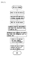
- FIG. 5 shows the process at the time of storing an article in the automated warehouse.
- the conveyor reads an ID tag of the article, and transmits the read data to the control unit.
- the control unit collates the received data with storage schedule data, and inspects the article to be stored in the warehouse.
- the ID tag of the bucket is read by the ID reader.
- the control unit associates the ID of the article with the ID of the bucket, and stores the associated data.
- the control unit determines the rack address for storing the bucket, and writes the rack address and the unique ID of the article in the ID tag of the bucket.
- the bucket is transferred to the stacker crane.
- the rack address is read from the ID tag of the bucket by the ID reader provided at the hoisting frame, and the article is stored at the rack address.
- FIG. 6 shows an algorism of the inventory check process.
- the stacker crane moves inside the rack of the automated warehouse, and reads the ID tag of the bucket at each rack address to determine the list of unique IDs of articles. Then, the list is transmitted to the control unit, and collated with the data of the control unit. After the ID tag of the bucket is read at every rack address, the inventory check is finished. In this manner, the inventory check is performed easily.
- the bucket is used as the carrier.
- a pallet or a tray may be used as the carrier.
- two ID readers may be provided only at the station.
- one ID reader/writer may be provided at the station.
- only the ID reader may be provided.
- the ID reader/writer may be provided.
- the ID tags are attached to both of the article and the bucket, and the rack address for storing the bucket is not fixed.
- the present invention is not limited in this respect.
- the embodiment can be modified in the following manner.
Landscapes
- Engineering & Computer Science (AREA)
- Business, Economics & Management (AREA)
- Economics (AREA)
- Mechanical Engineering (AREA)
- Quality & Reliability (AREA)
- Human Resources & Organizations (AREA)
- Marketing (AREA)
- Operations Research (AREA)
- Entrepreneurship & Innovation (AREA)
- Strategic Management (AREA)
- Tourism & Hospitality (AREA)
- Physics & Mathematics (AREA)
- General Business, Economics & Management (AREA)
- General Physics & Mathematics (AREA)
- Theoretical Computer Science (AREA)
- Development Economics (AREA)
- Warehouses Or Storage Devices (AREA)
Abstract
Description
- The present invention relates to an automated warehouse. In particular, the present invention relates to a technique of controlling a transportation apparatus in a warehouse at the time of storing an article in the warehouse.
- In an automated warehouse, at the time of storing an article in the warehouse, a carrier such as a bucket, a pallet, or a tray is transferred to a transportation apparatus such as a stacker crane in the warehouse. The transportation apparatus transports the article in accordance with an instruction from a control unit designating a rack address for storing the article. Therefore, each time an article is stored in the warehouse, the control unit needs to communicate with the transportation apparatus. According to the disclosure of
Japanese Laid-Open Patent Publication No. 5-81490 - An object of the preset invention is to eliminate the necessity of communication from a control unit to a transportation apparatus for transmitting data of a storage position at the time of storing an article in an automated warehouse.
Secondary object of the present invention is to eliminate the necessity of associating racks and buckets to have one-to-one correspondence for making it easier to manage the automated warehouse.
Secondary object of the present invention is to make it easier to carry out an inventory check of articles. - The present invention relates to an automated warehouse transporting an article set in a carrier between a station and a rack by a transportation apparatus. An ID tag is attached to the carrier, and a rack address is written in the ID tag. The transportation apparatus is provided with a reader for reading the ID tag for transporting the carrier to the rack address read from the ID tag of the carrier. For example, an RFID tag is used as the ID tag. The rack address is an address indicating the storage position in the rack.
- It is preferable that an ID writer for writing data in the ID tag is provided at the station, and the rack address of a transportation destination is written in the ID tag of the carrier.
- In particular, it is preferable that data of the article set in the carrier is written in the ID tag by the ID writer at the station.
- According to the present invention, since the transportation apparatus can determine the rack address of the storage destination from the ID tag of the carrier, at the time of storing an article in the warehouse, communication from the control unit to the transportation apparatus for transmitting the rack address of the storage destination is not required. In particular, since data of the ID tag attached to the carrier itself is used, even in the case of implementing complicated control, the article is not transported to a wrong transportation destination. For example, in the case of storing articles in a plurality of carriers successively, even if the order of carriers is changed at the station, it is possible to store the articles in the carriers at the correct rack addresses.
- In the case where an ID writer for writing data in the ID tag is provided at the station, and the rack address of a transportation destination is written in the ID tag of the carrier, the rack address for storing the carrier can be changed. Therefore, the automated warehouse can be operated freely. For example, the rack address of the carrier can be changed in accordance to the next retrieval schedule of the article. Further, if any of the rack address becomes empty after retrieval of a carrier, another carrier can be stored at the vacant rack address.
- Further, since data of the article set in the carrier (article in stock) is written in the ID tag by the ID writer at the station, the inventory check can be carried out easily, and the data of the article set in the carrier can be obtained by reading the ID tag of the carrier.
-
- FIG. 1 is a view showing the layout of an automated warehouse according to an embodiment.
- FIG. 2 is a view schematically showing the layout of ID readers at a station and a stacker crane according to the embodiment.
- FIG. 3 is a diagram showing data structure of ID tags according to the embodiment.
- FIG. 4 is a diagram showing the layout of the ID readers in the automated warehouse according to the embodiment.
- FIG. 5 is a flowchart showing a data processing algorithm at the time of storing an article in the warehouse according to the embodiment.
- FIG. 6 is a flowchart showing a data processing algorithm at the time of carrying out an inventory check in the warehouse according to the embodiment. Brief Description of the Symbols
- 2
Automated warehouse 4Rack 6 Stackercrane 7 Hoistingframe 8Station 10 Conveyor 12-16ID reader 20 Control unit forautomated warehouse 22Article 24Bucket 26 ID tag ofarticle 28 ID tag ofbucket 30 Terminal - Hereinafter, an embodiment in the most preferred form for carrying out the present invention will be described.
- An
automated warehouse 2 according to the embodiment will be described with reference to FIGS. 1 to 6. In the drawings,reference numerals 4 denote racks. For example, theracks 4 are provided on both sides of a travel route of a transportation apparatus such as astacker crane 6 in thewarehouse 2. For example, the rack address is designated as (1st row, 2nd group, 3rd stage). Areference numeral 7 denotes an hoisting frame of thestacker crane 6.Reference numerals stations 8 may be designated for storage, for retrieval, or for picking. However, these designations are not essential. In the embodiment,conveyors stations conveyor 10 is regarded as part of thestation 8. -
ID readers 12 are provided at theconveyors 10 or thestations 8.ID readers 14 are provided at thestation 8. TheID reader 14 is an ID reader/writer that can also be used as an ID writer. Further, anID reader 16 is provided at the hoistingframe 7. TheID readers ID readers reference numeral 20 denotes a control unit for theautomated warehouse 2. - FIG. 2 shows the process regarding the ID tag at the time of storing an article in the
warehouse 2, or retrieving an article from thewarehouse 2. Areference numeral 22 denotes an article to be stored/retrieved. For example, anID tag 26 is attached to thearticle 22. Areference numeral 24 denotes a bucket as an example of a carrier, and anID tag 28 is attached to thebucket 24. Alternatively, a pallet or a tray with an ID tag may be used as the carrier. TheID reader 12 reads data of theID tag 26 of an article to be stored/retrieved, and transmits the read data to thecontrol unit 20. TheID reader 14 reads data of the ID tag of thebucket 24, and for example, transmits the ID of thebucket 24, a list of IDs of articles in stock (at the time of retrieval), or the like to thecontrol unit 20. TheID reader 14 receives data of a rack address for storing thebucket 24 from thecontrol unit 20, and writes the data in theID tag 28. After thestacker crane 6 transfers thebucket 24 to thehoisting frame 7, thestacker crane 6 reads the rack address from theID tag 28, and transports thebucket 24 to the rack address. Communication between theID readers control unit 20 can be carried out easily utilizing the ground wiring or the like. - FIG. 3 shows data of the
ID tag 26 of the article and data of theID tag 28 of the bucket. TheID tag 26 of the article stores data about the origin of the article, such as a manufacturer code, and data for identifying the type of the article such as a product number, a product type, a shipment date, a collection date, and a unique ID assigned to each article. Other than the above, theID tag 26 may store data such as a use-by date, a price, retrieval destination, and remarks. TheID tag 28 of the bucket stores an ID of the bucket as a bucket number, a rack address, and a list of unique IDs ofarticles 22 placed (set) in thebucket 24. Instead of the list of unique IDs, theID tag 28 may store a manufacturer code, a product number, the number of products, and a storage date. It should be noted that IDs of the ID tags 26 of the articles and IDs of theID tag 28 of the buckets should not be overlapped with each other. - FIG. 4 shows the relationship between the
control unit 20 and theID readers 12 to 16. In the specification, it should be noted that the ID reader includes an ID reader/writer. Thecontrol unit 20 has a database for performing rack management, bucket management, article management, storage/retrieval management, and the entire inventory management or the like. Further, a suitable interface is provided for carrying out communication with, e.g., thestacker crane 6, thestation 8, theconveyor 10, and the terminal 30. In the rack management, information about which rack is vacant, and which rack contains thebucket 24 is stored, e.g., for each rack address. In the bucket management, for each bucket ID, the location (e.g., rack address) of the bucket, and IDs of articles in the bucket are stored. In the article management, manufacturer codes, product codes, unique IDs, and storage date or the like of articles in stock are stored. In the storage/retrieval management, the ID of the article for storage/retrieval read by theID reader 12 is collated with data of the article for storage/retrieval transmitted from the terminal 30 or the like. - FIG. 5 shows the process at the time of storing an article in the automated warehouse. The conveyor reads an ID tag of the article, and transmits the read data to the control unit. The control unit collates the received data with storage schedule data, and inspects the article to be stored in the warehouse. At the station, the ID tag of the bucket is read by the ID reader. The control unit associates the ID of the article with the ID of the bucket, and stores the associated data. Further, the control unit determines the rack address for storing the bucket, and writes the rack address and the unique ID of the article in the ID tag of the bucket. Then, the bucket is transferred to the stacker crane. The rack address is read from the ID tag of the bucket by the ID reader provided at the hoisting frame, and the article is stored at the rack address. As a result, at the time of storing the article in the warehouse, the necessity of communication from the control unit to the stacker crane for transmitting the rack address is eliminated.
- FIG. 6 shows an algorism of the inventory check process. The stacker crane moves inside the rack of the automated warehouse, and reads the ID tag of the bucket at each rack address to determine the list of unique IDs of articles. Then, the list is transmitted to the control unit, and collated with the data of the control unit. After the ID tag of the bucket is read at every rack address, the inventory check is finished. In this manner, the inventory check is performed easily.
- In the embodiment, the bucket is used as the carrier. Alternatively, a pallet or a tray may be used as the carrier. Further, instead of providing two ID readers at the conveyor and the station, two ID readers may be provided only at the station. In the case where reading of the ID of the article, and reading and writing of the ID of the bucket can be carried out at the same position, one ID reader/writer may be provided at the station. Further, in the case where writing of data in the ID tag is not performed, only the ID reader may be provided. In the case where records of transportation and storage are written in the ID tag, the ID reader/writer may be provided.
- In the embodiment, the following advantages can be obtained.
- (1) It is not necessary for the control unit to notify the storage destination of the bucket to the stacker crane. Further, the rack address can be obtained from the ID tag of the bucket itself. Therefore, no confusion occurs in the order of the control. Even if the order of buckets is switched mistakenly, the article is not stored at the wrong rack address.
- (2) Since the rack address of the bucket is not fixed, it is possible to change the storage position depending on the expected time of retrieving the article. Further, even if the bucket is transported to the outside of the automated warehouse, the racks do not become empty.
- (3) In the case where the ID of the article or data of the article is written in the ID tag of the bucket, it is possible to carry out an inventory check easily. Further, it is possible to obtain information about the article from the bucket itself. For example, the bucket can be transported without the control of the control unit.
- In the embodiment, the ID tags are attached to both of the article and the bucket, and the rack address for storing the bucket is not fixed. However, the present invention is not limited in this respect. However, for example, the embodiment can be modified in the following manner.
- (1) The buckets are associated with the rack addresses to have one-to-one correspondence. The rack address for storing the bucket is fixed. In this case, the ID reader at the station reads the rack address, and the control unit stores the read rack address. The stacker crane stores the bucket at the rack address read from the ID tag.
- (2) No ID tag is attached to the article. ID data of the article is inputted from a terminal or the like. The ID data is stored in the control unit, and written in the ID tag of the bucket. It should be noted that if the ID data of the article is only stored in the control unit without writing it in the ID tag of the bucket, the inventory check becomes difficult.
Claims (3)
- An automated warehouse transporting an article set in a carrier between a station and a rack by a transportation apparatus, wherein
an ID tag is attached to the carrier, and a rack address is written in the ID tag; and
the transportation apparatus is provided with a reader for reading the ID tag for transporting the carrier to the rack address read from the ID tag of the carrier. - The automated warehouse of claim 1, wherein an ID writer for writing data in the ID tag is provided at the station, and the rack address of a transportation destination is written in the ID tag of the carrier.
- The automated warehouse of claim 2, wherein data of the article set in the carrier is written in the ID tag by the ID writer at the station.
Applications Claiming Priority (2)
| Application Number | Priority Date | Filing Date | Title |
|---|---|---|---|
| JP2004350200 | 2004-12-02 | ||
| PCT/JP2005/022072 WO2006059675A1 (en) | 2004-12-02 | 2005-12-01 | Automatic warehouse |
Publications (3)
| Publication Number | Publication Date |
|---|---|
| EP1818285A1 true EP1818285A1 (en) | 2007-08-15 |
| EP1818285A4 EP1818285A4 (en) | 2009-12-23 |
| EP1818285B1 EP1818285B1 (en) | 2012-04-25 |
Family
ID=36565108
Family Applications (1)
| Application Number | Title | Priority Date | Filing Date |
|---|---|---|---|
| EP05811422A Expired - Fee Related EP1818285B1 (en) | 2004-12-02 | 2005-12-01 | Automatic warehouse |
Country Status (8)
| Country | Link |
|---|---|
| US (1) | US20070296585A1 (en) |
| EP (1) | EP1818285B1 (en) |
| JP (1) | JP4730617B2 (en) |
| KR (1) | KR100793198B1 (en) |
| CN (1) | CN1914102B (en) |
| HK (1) | HK1099543A1 (en) |
| TW (1) | TW200621600A (en) |
| WO (1) | WO2006059675A1 (en) |
Cited By (1)
| Publication number | Priority date | Publication date | Assignee | Title |
|---|---|---|---|---|
| WO2020094495A3 (en) * | 2018-11-05 | 2020-07-16 | Dipl Ing Gasper Werner | Method for automating product flows in a warehouse, and storage container/system for use in this kind of method |
Families Citing this family (13)
| Publication number | Priority date | Publication date | Assignee | Title |
|---|---|---|---|---|
| US7669763B2 (en) * | 2004-06-23 | 2010-03-02 | Sap Ag | Methods and system for managing stock |
| US7770792B2 (en) | 2004-06-23 | 2010-08-10 | Sap Ag | Methods and systems for managing stock transportation |
| US8855805B2 (en) * | 2009-06-02 | 2014-10-07 | Murata Machinery, Ltd. | Conveyance vehicle system |
| JP5321913B2 (en) * | 2009-12-07 | 2013-10-23 | 株式会社ダイフク | Goods storage facility |
| KR101661633B1 (en) * | 2012-04-05 | 2016-09-30 | 무라다기카이가부시끼가이샤 | Conveyance system |
| CN102975190B (en) * | 2012-12-07 | 2015-03-04 | 四川省星达包装设备制造有限公司 | Intelligent die warehouse and control method thereof |
| US20150284231A1 (en) * | 2014-04-05 | 2015-10-08 | RF Identity, Inc. | Systems and methods for validation of personal protection equipment on aerial work platforms |
| JP6704128B2 (en) * | 2014-06-16 | 2020-06-03 | トーヨーカネツ株式会社 | Goods storage sorting device |
| SG11201803032RA (en) * | 2015-10-23 | 2018-05-30 | Sato Holdings Kk | Storage and retrieval management system, storage and retrieval management method, and program |
| CN106269541A (en) * | 2016-08-23 | 2017-01-04 | 顺丰速运有限公司 | Method for sorting and sorting system for sorting system |
| CN109345699B (en) * | 2018-09-19 | 2022-01-21 | 安徽福家智能科技有限公司 | Single-layer independent control equipment and method for vending machine |
| KR20240048026A (en) * | 2022-09-30 | 2024-04-12 | 쿠팡 주식회사 | Electronic device and operation method thereof |
| KR20240048025A (en) * | 2022-09-30 | 2024-04-12 | 쿠팡 주식회사 | Electronic device and operation method thereof |
Citations (6)
| Publication number | Priority date | Publication date | Assignee | Title |
|---|---|---|---|---|
| JPS63212606A (en) * | 1987-03-02 | 1988-09-05 | Daifuku Co Ltd | Article conveyance equipment |
| US5006996A (en) * | 1988-03-26 | 1991-04-09 | Fuji Electric Co., Ltd. | System of conveying, storing, retrieving and distributing articles of manufacture |
| DE9306107U1 (en) * | 1993-04-19 | 1994-08-25 | Rotring Int Gmbh | Device for storing position data of pallets |
| EP0645322A1 (en) * | 1993-09-23 | 1995-03-29 | Quelle Schickedanz AG & Co. | Method for distributing return articles in a mailer dispatchcenter, in particular of clothing |
| US5472309A (en) * | 1985-05-13 | 1995-12-05 | Computer Aided Systems, Inc. | System for delivery |
| US5582497A (en) * | 1992-01-29 | 1996-12-10 | Wing Labo Co., Ltd. | Automatic warehouse system |
Family Cites Families (18)
| Publication number | Priority date | Publication date | Assignee | Title |
|---|---|---|---|---|
| JPS57156906A (en) | 1981-03-20 | 1982-09-28 | Nec Corp | Automated warehouse |
| JPH04173699A (en) * | 1990-11-02 | 1992-06-22 | Nippon Yusoki Co Ltd | Misdelivery preventive device of radio lan system |
| JPH0581490A (en) | 1991-09-20 | 1993-04-02 | Murata Mach Ltd | Irregular processing method for id card use system |
| JPH0873009A (en) * | 1994-09-01 | 1996-03-19 | Toyota Autom Loom Works Ltd | Inventory management system |
| TW386875B (en) * | 1995-01-11 | 2000-04-11 | Shinko Electric Co Ltd | Transportation system |
| DE19516696A1 (en) * | 1995-05-06 | 1996-11-07 | Hans Joachim Dipl Ing Eberhard | Procedures to identify and control the delivery and return delivery of press products |
| JPH10182096A (en) * | 1996-12-19 | 1998-07-07 | Sekisui Chem Co Ltd | Cargo handling system using id tag and cargo handling method |
| JP3884819B2 (en) | 1997-03-18 | 2007-02-21 | 横浜ゴム株式会社 | Compound information grant method |
| US6148291A (en) * | 1998-01-26 | 2000-11-14 | K & T Of Lorain, Ltd. | Container and inventory monitoring methods and systems |
| JP2000103505A (en) * | 1998-09-30 | 2000-04-11 | Sekisui Chem Co Ltd | Pallet control system |
| KR100395934B1 (en) * | 2000-01-04 | 2003-08-27 | 삼성전자주식회사 | Automated storage system with multi crane and method of controlling the same system |
| CN1157949C (en) * | 2000-12-15 | 2004-07-14 | 北京永新同方信息工程有限公司 | Cable television network based interactive television news transmitting and receiving system |
| EP1246094A1 (en) * | 2001-03-27 | 2002-10-02 | TELEFONAKTIEBOLAGET L M ERICSSON (publ) | Container surveillance system and related method |
| US6669089B2 (en) * | 2001-11-12 | 2003-12-30 | 3M Innovative Properties Co | Radio frequency identification systems for asset tracking |
| US6895301B2 (en) * | 2002-07-15 | 2005-05-17 | Distrobot Systems, Inc. | Material handling system using autonomous mobile drive units and movable inventory trays |
| US7865398B2 (en) * | 2003-09-30 | 2011-01-04 | Microsoft Corporation | Radio frequency identification tag on picking container and display of picklist to order filler |
| US7614555B2 (en) * | 2004-09-09 | 2009-11-10 | The Gillette Company | RFID sensor array |
| US7336177B2 (en) * | 2005-08-25 | 2008-02-26 | Kimberly-Clark Worldwide, Inc. | RFID system and method for tracking individual articles |
-
2005
- 2005-08-03 TW TW094126346A patent/TW200621600A/en unknown
- 2005-12-01 EP EP05811422A patent/EP1818285B1/en not_active Expired - Fee Related
- 2005-12-01 KR KR1020067011495A patent/KR100793198B1/en active IP Right Grant
- 2005-12-01 CN CN2005800039195A patent/CN1914102B/en not_active Expired - Fee Related
- 2005-12-01 WO PCT/JP2005/022072 patent/WO2006059675A1/en active Application Filing
- 2005-12-01 US US11/631,791 patent/US20070296585A1/en not_active Abandoned
- 2005-12-01 JP JP2006520574A patent/JP4730617B2/en not_active Expired - Fee Related
-
2007
- 2007-05-29 HK HK07105617.5A patent/HK1099543A1/en not_active IP Right Cessation
Patent Citations (6)
| Publication number | Priority date | Publication date | Assignee | Title |
|---|---|---|---|---|
| US5472309A (en) * | 1985-05-13 | 1995-12-05 | Computer Aided Systems, Inc. | System for delivery |
| JPS63212606A (en) * | 1987-03-02 | 1988-09-05 | Daifuku Co Ltd | Article conveyance equipment |
| US5006996A (en) * | 1988-03-26 | 1991-04-09 | Fuji Electric Co., Ltd. | System of conveying, storing, retrieving and distributing articles of manufacture |
| US5582497A (en) * | 1992-01-29 | 1996-12-10 | Wing Labo Co., Ltd. | Automatic warehouse system |
| DE9306107U1 (en) * | 1993-04-19 | 1994-08-25 | Rotring Int Gmbh | Device for storing position data of pallets |
| EP0645322A1 (en) * | 1993-09-23 | 1995-03-29 | Quelle Schickedanz AG & Co. | Method for distributing return articles in a mailer dispatchcenter, in particular of clothing |
Non-Patent Citations (1)
| Title |
|---|
| See also references of WO2006059675A1 * |
Cited By (1)
| Publication number | Priority date | Publication date | Assignee | Title |
|---|---|---|---|---|
| WO2020094495A3 (en) * | 2018-11-05 | 2020-07-16 | Dipl Ing Gasper Werner | Method for automating product flows in a warehouse, and storage container/system for use in this kind of method |
Also Published As
| Publication number | Publication date |
|---|---|
| WO2006059675A1 (en) | 2006-06-08 |
| JP4730617B2 (en) | 2011-07-20 |
| TW200621600A (en) | 2006-07-01 |
| CN1914102A (en) | 2007-02-14 |
| US20070296585A1 (en) | 2007-12-27 |
| JPWO2006059675A1 (en) | 2008-06-05 |
| EP1818285A4 (en) | 2009-12-23 |
| KR100793198B1 (en) | 2008-01-10 |
| EP1818285B1 (en) | 2012-04-25 |
| HK1099543A1 (en) | 2007-08-17 |
| CN1914102B (en) | 2010-05-12 |
| KR20070052689A (en) | 2007-05-22 |
Similar Documents
| Publication | Publication Date | Title |
|---|---|---|
| EP1818285A1 (en) | Automatic warehouse | |
| EP1818286B1 (en) | Storing system | |
| US9428295B2 (en) | Modular material handling system for order fulfillment | |
| JP5508259B2 (en) | Sorting system and method | |
| EP1818284A1 (en) | Automatic warehouse | |
| EP1764321A1 (en) | Product management system | |
| CN101410312A (en) | Article control system and article control method | |
| JPWO2005110896A1 (en) | Warehouse management system | |
| CN111620032A (en) | Goods checking method and system | |
| JP7265994B2 (en) | Dynamic storage device and dynamic access management method | |
| US20100176964A1 (en) | Inspection system and inspection method | |
| JP2002240913A (en) | Article control system using mark and tag | |
| CN111605945B (en) | Article warehousing system and article warehousing method | |
| EP2335838B1 (en) | Sorting system and method using a portable device | |
| JP7067970B2 (en) | Transport system | |
| JP3705195B2 (en) | Warehouse management system and warehouse management program | |
| JP4744932B2 (en) | Article collection apparatus and method | |
| JP2006076758A (en) | Article management system and article management method | |
| JP2010241570A (en) | System and method for sorting loads | |
| JP2006027810A (en) | Warehouse control system | |
| JP2019156559A (en) | Conveyance system | |
| CN218173450U (en) | Storage scheduling system | |
| JP2007254147A (en) | Conveying system | |
| JP3121376U (en) | Warehouse storage management device | |
| JPS63212605A (en) | Article taking-out equipment |
Legal Events
| Date | Code | Title | Description |
|---|---|---|---|
| PUAI | Public reference made under article 153(3) epc to a published international application that has entered the european phase |
Free format text: ORIGINAL CODE: 0009012 |
|
| 17P | Request for examination filed |
Effective date: 20060614 |
|
| AK | Designated contracting states |
Kind code of ref document: A1 Designated state(s): DE FR GB IT |
|
| DAX | Request for extension of the european patent (deleted) | ||
| RBV | Designated contracting states (corrected) |
Designated state(s): DE FR GB IT |
|
| A4 | Supplementary search report drawn up and despatched |
Effective date: 20091124 |
|
| RIC1 | Information provided on ipc code assigned before grant |
Ipc: G06Q 10/00 20060101ALI20091118BHEP Ipc: B65G 1/137 20060101AFI20060613BHEP |
|
| 17Q | First examination report despatched |
Effective date: 20100426 |
|
| GRAP | Despatch of communication of intention to grant a patent |
Free format text: ORIGINAL CODE: EPIDOSNIGR1 |
|
| GRAS | Grant fee paid |
Free format text: ORIGINAL CODE: EPIDOSNIGR3 |
|
| GRAA | (expected) grant |
Free format text: ORIGINAL CODE: 0009210 |
|
| AK | Designated contracting states |
Kind code of ref document: B1 Designated state(s): DE FR GB IT |
|
| REG | Reference to a national code |
Ref country code: GB Ref legal event code: FG4D |
|
| REG | Reference to a national code |
Ref country code: DE Ref legal event code: R096 Ref document number: 602005033914 Country of ref document: DE Effective date: 20120621 |
|
| PG25 | Lapsed in a contracting state [announced via postgrant information from national office to epo] |
Ref country code: IT Free format text: LAPSE BECAUSE OF FAILURE TO SUBMIT A TRANSLATION OF THE DESCRIPTION OR TO PAY THE FEE WITHIN THE PRESCRIBED TIME-LIMIT Effective date: 20120425 |
|
| PLBE | No opposition filed within time limit |
Free format text: ORIGINAL CODE: 0009261 |
|
| STAA | Information on the status of an ep patent application or granted ep patent |
Free format text: STATUS: NO OPPOSITION FILED WITHIN TIME LIMIT |
|
| 26N | No opposition filed |
Effective date: 20130128 |
|
| REG | Reference to a national code |
Ref country code: DE Ref legal event code: R097 Ref document number: 602005033914 Country of ref document: DE Effective date: 20130128 |
|
| GBPC | Gb: european patent ceased through non-payment of renewal fee |
Effective date: 20121201 |
|
| REG | Reference to a national code |
Ref country code: FR Ref legal event code: ST Effective date: 20130830 |
|
| PG25 | Lapsed in a contracting state [announced via postgrant information from national office to epo] |
Ref country code: GB Free format text: LAPSE BECAUSE OF NON-PAYMENT OF DUE FEES Effective date: 20121201 Ref country code: FR Free format text: LAPSE BECAUSE OF NON-PAYMENT OF DUE FEES Effective date: 20130102 |
|
| PGFP | Annual fee paid to national office [announced via postgrant information from national office to epo] |
Ref country code: DE Payment date: 20151211 Year of fee payment: 11 |
|
| REG | Reference to a national code |
Ref country code: DE Ref legal event code: R119 Ref document number: 602005033914 Country of ref document: DE |
|
| PG25 | Lapsed in a contracting state [announced via postgrant information from national office to epo] |
Ref country code: DE Free format text: LAPSE BECAUSE OF NON-PAYMENT OF DUE FEES Effective date: 20170701 |