EP1804402A1 - System and method for reducing radio frequency interference between a wireless communication device and a speaker - Google Patents
System and method for reducing radio frequency interference between a wireless communication device and a speaker Download PDFInfo
- Publication number
- EP1804402A1 EP1804402A1 EP05111860A EP05111860A EP1804402A1 EP 1804402 A1 EP1804402 A1 EP 1804402A1 EP 05111860 A EP05111860 A EP 05111860A EP 05111860 A EP05111860 A EP 05111860A EP 1804402 A1 EP1804402 A1 EP 1804402A1
- Authority
- EP
- European Patent Office
- Prior art keywords
- power transmission
- transmission level
- wireless device
- predefined
- event
- Prior art date
- Legal status (The legal status is an assumption and is not a legal conclusion. Google has not performed a legal analysis and makes no representation as to the accuracy of the status listed.)
- Granted
Links
- 238000004891 communication Methods 0.000 title claims abstract description 25
- 238000000034 method Methods 0.000 title claims abstract description 17
- 230000005540 biological transmission Effects 0.000 claims abstract description 67
- 238000001514 detection method Methods 0.000 claims description 22
- 238000012544 monitoring process Methods 0.000 claims description 5
- 230000000977 initiatory effect Effects 0.000 claims description 4
- 230000001960 triggered effect Effects 0.000 claims description 4
- 238000013500 data storage Methods 0.000 claims description 2
- 230000001419 dependent effect Effects 0.000 claims 4
- 238000010586 diagram Methods 0.000 description 2
- 230000003068 static effect Effects 0.000 description 2
- 230000003111 delayed effect Effects 0.000 description 1
- 230000035755 proliferation Effects 0.000 description 1
Images


Classifications
-
- H—ELECTRICITY
- H04—ELECTRIC COMMUNICATION TECHNIQUE
- H04W—WIRELESS COMMUNICATION NETWORKS
- H04W52/00—Power management, e.g. TPC [Transmission Power Control], power saving or power classes
- H04W52/04—TPC
- H04W52/18—TPC being performed according to specific parameters
- H04W52/24—TPC being performed according to specific parameters using SIR [Signal to Interference Ratio] or other wireless path parameters
- H04W52/243—TPC being performed according to specific parameters using SIR [Signal to Interference Ratio] or other wireless path parameters taking into account interferences
-
- H—ELECTRICITY
- H04—ELECTRIC COMMUNICATION TECHNIQUE
- H04B—TRANSMISSION
- H04B1/00—Details of transmission systems, not covered by a single one of groups H04B3/00 - H04B13/00; Details of transmission systems not characterised by the medium used for transmission
- H04B1/02—Transmitters
- H04B1/04—Circuits
- H04B1/0475—Circuits with means for limiting noise, interference or distortion
-
- H—ELECTRICITY
- H04—ELECTRIC COMMUNICATION TECHNIQUE
- H04B—TRANSMISSION
- H04B15/00—Suppression or limitation of noise or interference
- H04B15/02—Reducing interference from electric apparatus by means located at or near the interfering apparatus
-
- H—ELECTRICITY
- H04—ELECTRIC COMMUNICATION TECHNIQUE
- H04W—WIRELESS COMMUNICATION NETWORKS
- H04W52/00—Power management, e.g. TPC [Transmission Power Control], power saving or power classes
- H04W52/04—TPC
-
- H—ELECTRICITY
- H04—ELECTRIC COMMUNICATION TECHNIQUE
- H04W—WIRELESS COMMUNICATION NETWORKS
- H04W52/00—Power management, e.g. TPC [Transmission Power Control], power saving or power classes
- H04W52/04—TPC
- H04W52/18—TPC being performed according to specific parameters
- H04W52/26—TPC being performed according to specific parameters using transmission rate or quality of service QoS [Quality of Service]
- H04W52/265—TPC being performed according to specific parameters using transmission rate or quality of service QoS [Quality of Service] taking into account the quality of service QoS
Definitions
- the wireless device 102 further includes an event unit 212 configured to implement a predefined event upon detection of noise by the noise detection unit 210. Further, an event monitor 214 is configured to return the transmission power level from the low transmission power level to the standard transmission power level in accordance with a predefined event threshold. A power level controller 216 is configured to adjust the power transmission level of the device as desired.
- Each of the noise detection unit 210, event unit 212, event monitor 214 and power level controller 216 can be implemented in hardware or software, or a combination thereof.
Landscapes
- Engineering & Computer Science (AREA)
- Computer Networks & Wireless Communication (AREA)
- Signal Processing (AREA)
- Mobile Radio Communication Systems (AREA)
- Transmitters (AREA)
- Input Circuits Of Receivers And Coupling Of Receivers And Audio Equipment (AREA)
- Transceivers (AREA)
Abstract
Description
- The invention relates generally to the transmission of data to and from a wireless communication device and specifically for a system and method for reducing interference between the wireless device and a proximate speaker while doing so.
- The advance of wireless communication networks has led to the proliferation of wireless communication devices that are used for the transfer of both voice and data. Personal Digital Assistants (PDAs) and smart-phones provide users with a device that enables them to communicate via voice communications, electronic mail (e-mail), Short Message Service (SMS) messages as well as instant messaging. Additionally, many of these devices also include web browsers and other applications that access a wide area network, such as the Internet, to provide the users with information.
- However, when these devices transmit data they can cause noise to be heard on nearby speakers, such as radio speakers, computer speakers, speakerphones, and the like as a result of interference there between. Accordingly, it can be seen that there is a need for a system and method that inhibits interference between a wireless device and a nearby speaker.
- In accordance with an aspect of the present invention there is preferably provided a method for reducing interference between a wireless communication device and a speaker, the method comprising the steps of: monitoring a microphone input for detecting noise created by the interference; and reducing a power transmission level of the wireless device from a standard power transmission level.
- In accordance with a further aspect of the present invention, the method preferably further includes the steps of initiating a predefined event; monitoring the predefined event to determine when a predefined event threshold is reached; and returning the power transmission level of the wireless device to the standard power transmission level when said predefined event threshold is reached.
- In accordance with yet a further aspect of the present invention there is preferably provided a wireless communication device configured to reduce interference with a speaker, the wireless communication device comprising: a noise detection unit configured to detect noise caused by the interference; and a power controller configured to reduce a power transmission level of the wireless device in response to the detection of noise by the noise detection unit.
- In accordance with yet a further aspect of the present invention, the device preferably includes an event unit configured to trigger an event in response to the detection of noise by the noise detection unit; and an event monitor configured to detect when the triggered event reaches a predefined event threshold and instruct the power controller to return the power transmission level of the wireless device to the standard power transmission level.
- In accordance with yet a further aspect of the present invention there is preferably provided a data storage device comprising instructions which, when executed on a wireless device, cause the wireless device to facilitate reduced interference with a speaker by implementing the steps of: monitoring a microphone input for detecting noise created by the interference; and reducing a power transmission level of the wireless device from a standard power transmission level.
- Embodiments of the invention will now be described by way of example only with reference to the following drawings in which:
- Figure 1 is a block diagram illustrating a situation with the potential for interference between a proximate wireless device and a speaker (prior art);
- Figure 2 is block diagram of a wireless device;
- Figure 3 is flow chart illustrating the operation of an embodiment of the invention; and
- Figure 4 is a flow chart illustrating the operation of an alternate embodiment of the invention.
- For convenience, like numerals in the description refer to like structures in the drawings. Referring to Figure 1, a sample environment in which interference exists between a wireless device and a speaker is illustrated generally by
numeral 100. In the present example, awireless device 102 is within close proximity of aspeaker 104, such as a speakerphone for example. Further, thewireless device 102 is in communication with acommunication network 108 via atransmission tower 106. - The
wireless device 102 includes adisplay 110 for presenting information to the user and aninput device 112, such as a touch screen, keypad, miniature keyboard, scroll bar or any combination thereof, for allowing the user to input data. Thewireless device 102 further includes amicrophone 114 for facilitating voice communication or voice commands and well as a built in speaker for facilitating audio output. These features are common in the art variations will be apparent to a person of ordinary skill in the art. - When the
wireless device 102 transmits data to thecommunication network 108 via thetransmission tower 106, noise is often emitted from thespeaker 104. The volume of the noise and the duration for which it lasts depends on a number of factors including radio frequency (RF) shielding of thespeaker 104, the distance between thespeaker 104 and thewireless device 102, and the strength of the signal emitted by thewireless device 102. - Referring to Figure 2, a more detailed view of the
wireless device 102 is illustrated. Thewireless device 102 includes state of the components such asmemory 202, aprocessor 204, acommunication interface 206 and an input/output interface 208. A person of ordinary skill in the art will appreciate that different devices are configured in accordance with the required specification and are not limited to the components described herein. - As described with reference to Figure 1, noise may be a problem due to interference between the
wireless device 102 and thespeaker 104. Therefore, thewireless device 102 further includes anoise detection unit 210 configured to detect noise created by interference with thespeaker 104. Specifically, thenoise detection unit 210 is configured to use themicrophone 114 to listen for noise. If noise is detected, a standard transmission power level used to transmit data from thehandheld device 102 to thetransmission tower 106 is reduced to a low transmission power level. - The
wireless device 102 further includes anevent unit 212 configured to implement a predefined event upon detection of noise by thenoise detection unit 210. Further, anevent monitor 214 is configured to return the transmission power level from the low transmission power level to the standard transmission power level in accordance with a predefined event threshold. Apower level controller 216 is configured to adjust the power transmission level of the device as desired. Each of thenoise detection unit 210,event unit 212,event monitor 214 andpower level controller 216 can be implemented in hardware or software, or a combination thereof. - Referring to Figure 3, a flow chart illustrating operation of the present embodiment is represented generally by
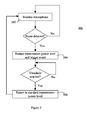
numeral 300. - In
step 302 thenoise detection unit 210 monitors themicrophone 114 for noise caused by interference between thespeaker 104 and thewireless device 102. Noise detection can be achieved using any one of a number of standard noise detection algorithms that is configured to identify the noise due to speaker interference. It will be appreciated by a person of ordinary skill in the art that different parameters of the noise detection algorithm may be configured differently depending on the implementation. - In the present embodiment, the
noise detection unit 210 only monitors themicrophone 114 when RF communication is occurring. It will be appreciated that in alternate embodiments, for example, thenoise detection unit 210 can monitor themicrophone 114 at all times, or only when thedevice 102 is receiving or transmitting data. If noise is detected, the operation continues atstep 304, otherwise it remains atstep 302. - In
step 304, the standard transmission power level used to transmit data from thewireless device 104 to thetransmission tower 106 is reduced to the low transmission power level for data transmission. The low transmission power level is configured to limit the interference with thespeaker 104, and thereby limit the noise emitted there from. - Further, at
step 304 an event is triggered and theevent unit 212 is initiated. In the present embodiment, theevent unit 212 is a timer. Depending on the implementation, the timer can be designed to count up or down. The operation then proceeds tostep 306. - In
step 306, theevent monitor 214 returns the transmission power level to the standard transmission power level in accordance with the predefined event threshold. For example, in the present embodiment, theevent monitor 214 monitors the timer until a predefined time has elapsed before returning the transmission power level to the standard transmission power level. - Accordingly, it will be apparent that for the duration in which the low power transmission level is applied, interference between the
wireless device 102 and thespeaker 104 is reduced. However, the reduction in transmission power may cause more transmission errors, which causes data retransmissions, or retries. Often the number of retries is sufficiently low that it is considered to be a worthwhile trade-off for the reduced interference. However, in some instances retries may be less desirable than others. - Referring to Figure 4, a flow chart illustrating an alternate embodiment of the present invention is illustrated generally by
numeral 400. In the present embodiment, the wireless device determines the type of data being transmitted in order to minimize the number of retries in certain circumstances. Specifically, anadditional step 402 is added betweensteps - In
step 402, a data determination unit determines the type of data being transmitted from thewireless device 102 to thetransmission tower 106. Although not shown in Figure 2, it will be appreciated that the data determination unit can be implemented on the device in hardware, software or a combination thereof. - If, for example, the data determination unit detects that the
wireless device 102 is transmitting such as acknowledgements for incoming data then the potential increase in retries is a good compromise for the reduced interference and the operation continues atstep 304. Other candidates for an acceptable increase in the number of retries include polling for e-mail or other data in a pull data environment. - Alternately, however, if the data determination unit determines that the type of data being transmitted from the
wireless device 102 to thetransmission tower 106 should use minimal retries, then the detection of interference is ignored, the transmission power level remains the same and the operation returns tostep 302. Data that requires minimal transfers may include voice communication and e-mails or other data transfers initiated by the user. Further, applications may be assigned a Quality of Service (QoS) indicator to assist making the decision whether or not the power level can be reduced. Applications assigned a high QoS indicator would require a higher power level and applications assigned a low QoS indicator could tolerate a lower power level. - Optionally, the return to step 302 from
step 402 is delayed in time to limit looping that may occur betweensteps step 402, it would be determined that the power transmission level should not be reduced and the operation would return once again to step 302. This loop would continue until either one of the conditions changes, while using resources on thewireless device 102. Accordingly, ifstep 402 includes a delay before returning to step 302, the probability that one of the conditions has changed is increased, thereby reducing the use of the wireless device's resources. - The embodiments described above either transmit at a standard power transmission level or a low power transmission level. In an alternate embodiment, for some data it may be possible simply not to transmit anything to the
communication network 108. Therefore, rather than transmit at a low power transmission level, thewireless device 102 simply does not acknowledge the data at all so thecommunication network 108 retransmits the data to thewireless device 102 at a later point in time. - Further, in the embodiments described above, the
event unit 212 is implemented as a timer. However, since the interference betweenwireless device 102 and thespeaker 104 is related largely to their proximity, theevent unit 212 may comprise a geospatial device such as accelerometer, global positioning system (GPS), motion sensors and the like. Optionally, theevent unit 212 includes both the geospatial device and the timer in case thespeaker 104 is in motion and the wireless device is stationary. - Therefore, at
step 304, when the event is triggered and theevent unit 212 is initiated, the geospatial device provides information relating to the position of thewireless device 102. For example, the GPS could provide the coordinates of thewireless device 102, while the accelerometer and motion sensor could determine motion. - At
step 306, the event monitor 214 monitors the position of thewireless device 102 as determined by the geospatial device to determine a distance of which thewireless device 102 has moved. Once the device has moved further than a predefined distance threshold, the transmission power level is returned to the standard transmission power level and the operation returns to step 302. If theevent unit 212 also includes the timer, the transmission power level is returned to the standard transmission power level and the operation returns to step 302 after a predefined time threshold has elapsed, even if thewireless device 102 does not move further than the predefined distance threshold. - The predefined distance threshold may be static and commonly defined for all circumstances. Alternately, the predefined distance threshold is dynamic and assigned in accordance with the volume of the detected noise. A greater volume of noise typically, although not necessarily, indicates greater interference between the
wireless device 102 and thespeaker 104. Accordingly, the greater the volume of detected noise, the larger the predefined distance threshold. - Similarly, the low transmission power level described above may either be static or dynamic. That is, one value may be used for the low transmission power level for all circumstances or a different value may be used for the low transmission power level depending upon the volume of the detected noise. As previously described, a greater volume of noise typically indicates greater interference between the
wireless device 102 and thespeaker 104. Accordingly, the greater the volume of detected noise, the lower the value selected for the low transmission power level. - Optionally, in the present embodiment the signal strength of the
wireless device 102 is an additional factor used to determine the value for transmission power level. A strong signal strength would allow a relatively low transmission power level, whereas a weak signal strength would require a relatively high transmission power level. - Although the subject application refers specifically to the use of
transmission towers 106 as an interface between thewireless device 102 and thecommunication network 108, any wireless communication interface may be used. - Further, although preferred embodiments of the invention have been described herein, it will be understood by those skilled in the art that variations may be made thereto without departing from the spirit of the invention or the scope of the appended claims.
Claims (20)
- A method for reducing interference between a wireless communication device and a speaker, the method comprising the steps of:monitoring a microphone input for detecting noise created by the interference; andreducing a power transmission level of the wireless device from a standard power transmission level.
- The method of claim 1, further comprising the steps of:initiating a predefined event;monitoring the predefined event to determine when a predefined event threshold is reached; andreturning the power transmission level of the wireless device to the standard power transmission level when said predefined event threshold is reached.
- The method of claim 1 or claim 2 further comprising the step of determining that data retransmissions are acceptable before reducing the power transmission level.
- The method of claim 3, wherein the step of determining that data retransmissions are acceptable comprises interpreting a Quality of Service indicator.
- The method of any one of claims 1 to 3, wherein the power transmission level is reduced to a low power transmission level.
- The method of claim 1 or claim 2, wherein the power transmission level is reduced by not transmitting data from the wireless device.
- The method of claim 2 or any one of claims 3 to 6 when dependent on claim 2, wherein the step of initiating the predefined event comprises starting a timer and the predefined event threshold is a predefined duration of time.
- The method of claim 2 or any one of claims 3 to 7 when dependent on claim 2, wherein the step of initiating the predefined event comprises determining a geospatial position of the wireless device and the predefined event threshold is a predefined distance travelled.
- The method of claim 8 wherein the geospatial position and predefined distance travelled are determined using any one or a combination of an accelerometer, global positioning system, and a motion sensor.
- A wireless communication device configured to reduce interference with a speaker, the wireless communication device comprising:a noise detection unit configured to detect noise caused by the interference; anda power controller configured to reduce a power transmission level of the wireless device in response to the detection of noise by the noise detection unit.
- The device of claim 10 further comprising:an event unit configured to trigger an event in response to the detection of noise by the noise detection unit; andan event monitor configured to detect when the triggered event reaches a predefined event threshold and instruct the power controller to return the power transmission level of the wireless device to the standard power transmission level.
- The device of claim 10 or claim 11 further comprising a data determination unit configured to determine if data retransmissions are acceptable before reducing the power transmission level.
- The device of claim 12, wherein the data determination unit is configured to determine that data retransmissions are acceptable in accordance with a Quality of Service indicator.
- The device of any one of claims 1 to 13, wherein the power controller is configured to reduce the power transmission level to a low power transmission level.
- The device of any one of claims 10 to 13, wherein the power controller is configured to reduce the power transmission level by not transmitting data from the wireless device.
- The device of claim 11 or any one of claims 12 to 15 when dependent on claim 11, wherein the event unit comprises a timer and the predefined event threshold is a predefined duration of time.
- The device of claim 11 or any one of claims 12 to 16 when dependent on claim 11, wherein the event unit comprises a geospatial positioning device configured to determine a geospatial position of the wireless device and the predefined event threshold is a predefined distance travelled.
- The device of claim 17 wherein the geospatial positioning device comprises any one or a combination of an accelerometer, global positioning system, and a motion sensor.
- A data storage medium comprising instructions which, when executed on a wireless device, cause the wireless device to facilitate reduced interference with a speaker by implementing the steps of any one of claims 1 to 9.
- A wireless communication system comprising a plurality of the wireless communication devices of any one of claims 10 to 18.
Priority Applications (4)
| Application Number | Priority Date | Filing Date | Title |
|---|---|---|---|
| EP05111860A EP1804402B1 (en) | 2005-12-08 | 2005-12-08 | System and method for reducing radio frequency interference between a wireless communication device and a speaker |
| DE602005004807T DE602005004807T2 (en) | 2005-12-08 | 2005-12-08 | Apparatus and method for reducing interference between a wireless device and a speaker |
| AT05111860T ATE386378T1 (en) | 2005-12-08 | 2005-12-08 | APPARATUS AND METHOD FOR REDUCING INTERFERENCE BETWEEN A WIRELESS DEVICE AND A SPEAKER |
| CA2570465A CA2570465C (en) | 2005-12-08 | 2006-12-06 | System and method for reducing radio frequency interference between a wireless communication device and a speaker |
Applications Claiming Priority (1)
| Application Number | Priority Date | Filing Date | Title |
|---|---|---|---|
| EP05111860A EP1804402B1 (en) | 2005-12-08 | 2005-12-08 | System and method for reducing radio frequency interference between a wireless communication device and a speaker |
Publications (2)
| Publication Number | Publication Date |
|---|---|
| EP1804402A1 true EP1804402A1 (en) | 2007-07-04 |
| EP1804402B1 EP1804402B1 (en) | 2008-02-13 |
Family
ID=35819884
Family Applications (1)
| Application Number | Title | Priority Date | Filing Date |
|---|---|---|---|
| EP05111860A Active EP1804402B1 (en) | 2005-12-08 | 2005-12-08 | System and method for reducing radio frequency interference between a wireless communication device and a speaker |
Country Status (4)
| Country | Link |
|---|---|
| EP (1) | EP1804402B1 (en) |
| AT (1) | ATE386378T1 (en) |
| CA (1) | CA2570465C (en) |
| DE (1) | DE602005004807T2 (en) |
Citations (3)
| Publication number | Priority date | Publication date | Assignee | Title |
|---|---|---|---|---|
| US5917812A (en) * | 1996-04-16 | 1999-06-29 | Qualcomm Incorporated | System and method for reducing interference generated by a digital communication device |
| US6122500A (en) * | 1996-01-24 | 2000-09-19 | Ericsson, Inc. | Cordless time-duplex phone with improved hearing-aid compatible mode |
| JP2005260535A (en) * | 2004-03-11 | 2005-09-22 | Matsushita Electric Ind Co Ltd | Speaker and module using the same, and electronic device and apparatus |
-
2005
- 2005-12-08 AT AT05111860T patent/ATE386378T1/en not_active IP Right Cessation
- 2005-12-08 DE DE602005004807T patent/DE602005004807T2/en active Active
- 2005-12-08 EP EP05111860A patent/EP1804402B1/en active Active
-
2006
- 2006-12-06 CA CA2570465A patent/CA2570465C/en active Active
Patent Citations (3)
| Publication number | Priority date | Publication date | Assignee | Title |
|---|---|---|---|---|
| US6122500A (en) * | 1996-01-24 | 2000-09-19 | Ericsson, Inc. | Cordless time-duplex phone with improved hearing-aid compatible mode |
| US5917812A (en) * | 1996-04-16 | 1999-06-29 | Qualcomm Incorporated | System and method for reducing interference generated by a digital communication device |
| JP2005260535A (en) * | 2004-03-11 | 2005-09-22 | Matsushita Electric Ind Co Ltd | Speaker and module using the same, and electronic device and apparatus |
Non-Patent Citations (1)
| Title |
|---|
| PATENT ABSTRACTS OF JAPAN vol. 2003, no. 12 5 December 2003 (2003-12-05) * |
Also Published As
| Publication number | Publication date |
|---|---|
| ATE386378T1 (en) | 2008-03-15 |
| EP1804402B1 (en) | 2008-02-13 |
| CA2570465A1 (en) | 2007-06-08 |
| DE602005004807T2 (en) | 2009-03-05 |
| CA2570465C (en) | 2010-04-13 |
| DE602005004807D1 (en) | 2008-03-27 |
Similar Documents
| Publication | Publication Date | Title |
|---|---|---|
| US8737923B2 (en) | System and method for reducing radio frequency interference between a wireless communication device and a speaker | |
| US11582791B2 (en) | PUCCH collision processing method and terminal | |
| WO2018103492A1 (en) | Method for setting wifi roaming, and terminal device | |
| CN110234124B (en) | Information transmission method and terminal equipment | |
| US20180176905A1 (en) | Communication method, communications apparatus, terminal, and base station | |
| CN109831359B (en) | Method for detecting connection state of data network and terminal equipment thereof | |
| CN107104763B (en) | Method and device for setting timeout retransmission duration | |
| CN110890943B (en) | Determination method, terminal equipment and network equipment | |
| CN108492837B (en) | Method, device and storage medium for detecting audio burst white noise | |
| CN111405112B (en) | Message prompting method and electronic equipment | |
| US20220369169A1 (en) | Sidelink transmission control method, transmit terminal, and receive terminal | |
| US11375497B2 (en) | Power configuration method and terminal | |
| US11523442B2 (en) | Random access resource selection method and terminal device | |
| CN110011766B (en) | Beam failure detection method, terminal and network equipment | |
| CN108307048B (en) | Message output method and device and mobile terminal | |
| WO2018103378A1 (en) | Method for sending data, and mobile terminal | |
| CN109561214B (en) | Call processing method and mobile terminal | |
| CN110475372B (en) | Uplink transmission method and terminal | |
| US20230007660A1 (en) | Resource selection method and device | |
| CN110149185B (en) | Method for determining CSI resource type, terminal and network side equipment | |
| EP1804402B1 (en) | System and method for reducing radio frequency interference between a wireless communication device and a speaker | |
| CN115118636A (en) | Method and device for determining network jitter state, electronic equipment and storage medium | |
| CN111132355B (en) | Semi-persistent scheduling transmission method, terminal and network equipment | |
| CN112911056A (en) | Audio recording calibration method and device and computer readable storage medium | |
| US11467801B2 (en) | Terminal device and control method |
Legal Events
| Date | Code | Title | Description |
|---|---|---|---|
| PUAI | Public reference made under article 153(3) epc to a published international application that has entered the european phase |
Free format text: ORIGINAL CODE: 0009012 |
|
| 17P | Request for examination filed |
Effective date: 20051208 |
|
| AK | Designated contracting states |
Kind code of ref document: A1 Designated state(s): AT BE BG CH CY CZ DE DK EE ES FI FR GB GR HU IE IS IT LI LT LU LV MC NL PL PT RO SE SI SK TR |
|
| AX | Request for extension of the european patent |
Extension state: AL BA HR MK YU |
|
| GRAP | Despatch of communication of intention to grant a patent |
Free format text: ORIGINAL CODE: EPIDOSNIGR1 |
|
| GRAS | Grant fee paid |
Free format text: ORIGINAL CODE: EPIDOSNIGR3 |
|
| GRAA | (expected) grant |
Free format text: ORIGINAL CODE: 0009210 |
|
| AK | Designated contracting states |
Kind code of ref document: B1 Designated state(s): AT BE BG CH CY CZ DE DK EE ES FI FR GB GR HU IE IS IT LI LT LU LV MC NL PL PT RO SE SI SK TR |
|
| AX | Request for extension of the european patent |
Extension state: AL BA HR MK YU |
|
| REG | Reference to a national code |
Ref country code: GB Ref legal event code: FG4D |
|
| REG | Reference to a national code |
Ref country code: CH Ref legal event code: EP |
|
| AKX | Designation fees paid |
Designated state(s): AT BE BG CH CY CZ DE DK EE ES FI FR GB GR HU IE IS IT LI LT LU LV MC NL PL PT RO SE SI SK TR |
|
| AXX | Extension fees paid |
Extension state: YU Payment date: 20051208 Extension state: HR Payment date: 20051208 Extension state: AL Payment date: 20051208 Extension state: BA Payment date: 20051208 Extension state: MK Payment date: 20051208 |
|
| REG | Reference to a national code |
Ref country code: IE Ref legal event code: FG4D |
|
| REF | Corresponds to: |
Ref document number: 602005004807 Country of ref document: DE Date of ref document: 20080327 Kind code of ref document: P |
|
| PG25 | Lapsed in a contracting state [announced via postgrant information from national office to epo] |
Ref country code: ES Free format text: LAPSE BECAUSE OF FAILURE TO SUBMIT A TRANSLATION OF THE DESCRIPTION OR TO PAY THE FEE WITHIN THE PRESCRIBED TIME-LIMIT Effective date: 20080524 Ref country code: FI Free format text: LAPSE BECAUSE OF FAILURE TO SUBMIT A TRANSLATION OF THE DESCRIPTION OR TO PAY THE FEE WITHIN THE PRESCRIBED TIME-LIMIT Effective date: 20080213 Ref country code: IS Free format text: LAPSE BECAUSE OF FAILURE TO SUBMIT A TRANSLATION OF THE DESCRIPTION OR TO PAY THE FEE WITHIN THE PRESCRIBED TIME-LIMIT Effective date: 20080613 |
|
| NLV1 | Nl: lapsed or annulled due to failure to fulfill the requirements of art. 29p and 29m of the patents act | ||
| PG25 | Lapsed in a contracting state [announced via postgrant information from national office to epo] |
Ref country code: AT Free format text: LAPSE BECAUSE OF FAILURE TO SUBMIT A TRANSLATION OF THE DESCRIPTION OR TO PAY THE FEE WITHIN THE PRESCRIBED TIME-LIMIT Effective date: 20080213 |
|
| PG25 | Lapsed in a contracting state [announced via postgrant information from national office to epo] |
Ref country code: LV Free format text: LAPSE BECAUSE OF FAILURE TO SUBMIT A TRANSLATION OF THE DESCRIPTION OR TO PAY THE FEE WITHIN THE PRESCRIBED TIME-LIMIT Effective date: 20080213 Ref country code: SI Free format text: LAPSE BECAUSE OF FAILURE TO SUBMIT A TRANSLATION OF THE DESCRIPTION OR TO PAY THE FEE WITHIN THE PRESCRIBED TIME-LIMIT Effective date: 20080213 Ref country code: BE Free format text: LAPSE BECAUSE OF FAILURE TO SUBMIT A TRANSLATION OF THE DESCRIPTION OR TO PAY THE FEE WITHIN THE PRESCRIBED TIME-LIMIT Effective date: 20080213 Ref country code: PL Free format text: LAPSE BECAUSE OF FAILURE TO SUBMIT A TRANSLATION OF THE DESCRIPTION OR TO PAY THE FEE WITHIN THE PRESCRIBED TIME-LIMIT Effective date: 20080213 |
|
| ET | Fr: translation filed | ||
| PG25 | Lapsed in a contracting state [announced via postgrant information from national office to epo] |
Ref country code: CZ Free format text: LAPSE BECAUSE OF FAILURE TO SUBMIT A TRANSLATION OF THE DESCRIPTION OR TO PAY THE FEE WITHIN THE PRESCRIBED TIME-LIMIT Effective date: 20080213 Ref country code: DK Free format text: LAPSE BECAUSE OF FAILURE TO SUBMIT A TRANSLATION OF THE DESCRIPTION OR TO PAY THE FEE WITHIN THE PRESCRIBED TIME-LIMIT Effective date: 20080213 Ref country code: NL Free format text: LAPSE BECAUSE OF FAILURE TO SUBMIT A TRANSLATION OF THE DESCRIPTION OR TO PAY THE FEE WITHIN THE PRESCRIBED TIME-LIMIT Effective date: 20080213 Ref country code: SK Free format text: LAPSE BECAUSE OF FAILURE TO SUBMIT A TRANSLATION OF THE DESCRIPTION OR TO PAY THE FEE WITHIN THE PRESCRIBED TIME-LIMIT Effective date: 20080213 Ref country code: PT Free format text: LAPSE BECAUSE OF FAILURE TO SUBMIT A TRANSLATION OF THE DESCRIPTION OR TO PAY THE FEE WITHIN THE PRESCRIBED TIME-LIMIT Effective date: 20080714 Ref country code: SE Free format text: LAPSE BECAUSE OF FAILURE TO SUBMIT A TRANSLATION OF THE DESCRIPTION OR TO PAY THE FEE WITHIN THE PRESCRIBED TIME-LIMIT Effective date: 20080513 |
|
| PG25 | Lapsed in a contracting state [announced via postgrant information from national office to epo] |
Ref country code: RO Free format text: LAPSE BECAUSE OF FAILURE TO SUBMIT A TRANSLATION OF THE DESCRIPTION OR TO PAY THE FEE WITHIN THE PRESCRIBED TIME-LIMIT Effective date: 20080213 |
|
| PLBE | No opposition filed within time limit |
Free format text: ORIGINAL CODE: 0009261 |
|
| STAA | Information on the status of an ep patent application or granted ep patent |
Free format text: STATUS: NO OPPOSITION FILED WITHIN TIME LIMIT |
|
| 26N | No opposition filed |
Effective date: 20081114 |
|
| PG25 | Lapsed in a contracting state [announced via postgrant information from national office to epo] |
Ref country code: LT Free format text: LAPSE BECAUSE OF FAILURE TO SUBMIT A TRANSLATION OF THE DESCRIPTION OR TO PAY THE FEE WITHIN THE PRESCRIBED TIME-LIMIT Effective date: 20080213 |
|
| PG25 | Lapsed in a contracting state [announced via postgrant information from national office to epo] |
Ref country code: BG Free format text: LAPSE BECAUSE OF FAILURE TO SUBMIT A TRANSLATION OF THE DESCRIPTION OR TO PAY THE FEE WITHIN THE PRESCRIBED TIME-LIMIT Effective date: 20080513 Ref country code: EE Free format text: LAPSE BECAUSE OF FAILURE TO SUBMIT A TRANSLATION OF THE DESCRIPTION OR TO PAY THE FEE WITHIN THE PRESCRIBED TIME-LIMIT Effective date: 20080213 |
|
| PG25 | Lapsed in a contracting state [announced via postgrant information from national office to epo] |
Ref country code: MC Free format text: LAPSE BECAUSE OF NON-PAYMENT OF DUE FEES Effective date: 20081231 Ref country code: CY Free format text: LAPSE BECAUSE OF FAILURE TO SUBMIT A TRANSLATION OF THE DESCRIPTION OR TO PAY THE FEE WITHIN THE PRESCRIBED TIME-LIMIT Effective date: 20080213 |
|
| PG25 | Lapsed in a contracting state [announced via postgrant information from national office to epo] |
Ref country code: IT Free format text: LAPSE BECAUSE OF FAILURE TO SUBMIT A TRANSLATION OF THE DESCRIPTION OR TO PAY THE FEE WITHIN THE PRESCRIBED TIME-LIMIT Effective date: 20080213 |
|
| PG25 | Lapsed in a contracting state [announced via postgrant information from national office to epo] |
Ref country code: IE Free format text: LAPSE BECAUSE OF NON-PAYMENT OF DUE FEES Effective date: 20081208 |
|
| PG25 | Lapsed in a contracting state [announced via postgrant information from national office to epo] |
Ref country code: LU Free format text: LAPSE BECAUSE OF NON-PAYMENT OF DUE FEES Effective date: 20081208 Ref country code: HU Free format text: LAPSE BECAUSE OF FAILURE TO SUBMIT A TRANSLATION OF THE DESCRIPTION OR TO PAY THE FEE WITHIN THE PRESCRIBED TIME-LIMIT Effective date: 20080814 |
|
| REG | Reference to a national code |
Ref country code: CH Ref legal event code: PL |
|
| PG25 | Lapsed in a contracting state [announced via postgrant information from national office to epo] |
Ref country code: TR Free format text: LAPSE BECAUSE OF FAILURE TO SUBMIT A TRANSLATION OF THE DESCRIPTION OR TO PAY THE FEE WITHIN THE PRESCRIBED TIME-LIMIT Effective date: 20080213 |
|
| PG25 | Lapsed in a contracting state [announced via postgrant information from national office to epo] |
Ref country code: CH Free format text: LAPSE BECAUSE OF NON-PAYMENT OF DUE FEES Effective date: 20091231 Ref country code: LI Free format text: LAPSE BECAUSE OF NON-PAYMENT OF DUE FEES Effective date: 20091231 Ref country code: GR Free format text: LAPSE BECAUSE OF FAILURE TO SUBMIT A TRANSLATION OF THE DESCRIPTION OR TO PAY THE FEE WITHIN THE PRESCRIBED TIME-LIMIT Effective date: 20080514 |
|
| REG | Reference to a national code |
Ref country code: DE Ref legal event code: R082 Ref document number: 602005004807 Country of ref document: DE Representative=s name: MERH-IP MATIAS ERNY REICHL HOFFMANN, DE |
|
| REG | Reference to a national code |
Ref country code: DE Ref legal event code: R082 Ref document number: 602005004807 Country of ref document: DE Representative=s name: MERH-IP MATIAS ERNY REICHL HOFFMANN, DE Effective date: 20140925 Ref country code: DE Ref legal event code: R081 Ref document number: 602005004807 Country of ref document: DE Owner name: BLACKBERRY LIMITED, WATERLOO, CA Free format text: FORMER OWNER: RESEARCH IN MOTION LTD., WATERLOO, ONTARIO, CA Effective date: 20140925 Ref country code: DE Ref legal event code: R082 Ref document number: 602005004807 Country of ref document: DE Representative=s name: MERH-IP MATIAS ERNY REICHL HOFFMANN PATENTANWA, DE Effective date: 20140925 |
|
| REG | Reference to a national code |
Ref country code: FR Ref legal event code: PLFP Year of fee payment: 11 |
|
| REG | Reference to a national code |
Ref country code: FR Ref legal event code: PLFP Year of fee payment: 12 |
|
| REG | Reference to a national code |
Ref country code: FR Ref legal event code: PLFP Year of fee payment: 13 |
|
| PGFP | Annual fee paid to national office [announced via postgrant information from national office to epo] |
Ref country code: DE Payment date: 20221228 Year of fee payment: 18 |
|
| PGFP | Annual fee paid to national office [announced via postgrant information from national office to epo] |
Ref country code: GB Payment date: 20231227 Year of fee payment: 19 |
|
| PGFP | Annual fee paid to national office [announced via postgrant information from national office to epo] |
Ref country code: FR Payment date: 20231227 Year of fee payment: 19 |