EP1804046A2 - Sample image obtaining apparatus, sample image obtaining system, and method for obtaining sample image - Google Patents
Sample image obtaining apparatus, sample image obtaining system, and method for obtaining sample image Download PDFInfo
- Publication number
- EP1804046A2 EP1804046A2 EP06026837A EP06026837A EP1804046A2 EP 1804046 A2 EP1804046 A2 EP 1804046A2 EP 06026837 A EP06026837 A EP 06026837A EP 06026837 A EP06026837 A EP 06026837A EP 1804046 A2 EP1804046 A2 EP 1804046A2
- Authority
- EP
- European Patent Office
- Prior art keywords
- slide glass
- sample
- cassette
- smeared
- image
- Prior art date
- Legal status (The legal status is an assumption and is not a legal conclusion. Google has not performed a legal analysis and makes no representation as to the accuracy of the status listed.)
- Granted
Links
- 238000000034 method Methods 0.000 title claims description 14
- 239000011521 glass Substances 0.000 claims abstract description 299
- 238000012546 transfer Methods 0.000 claims description 2
- 238000003384 imaging method Methods 0.000 abstract description 30
- 238000002360 preparation method Methods 0.000 abstract description 4
- 230000032258 transport Effects 0.000 description 125
- 210000004369 blood Anatomy 0.000 description 76
- 239000008280 blood Substances 0.000 description 76
- 230000006870 function Effects 0.000 description 29
- 230000005540 biological transmission Effects 0.000 description 17
- 238000003780 insertion Methods 0.000 description 16
- 230000037431 insertion Effects 0.000 description 16
- 238000010186 staining Methods 0.000 description 16
- OKKJLVBELUTLKV-UHFFFAOYSA-N Methanol Chemical compound OC OKKJLVBELUTLKV-UHFFFAOYSA-N 0.000 description 12
- 238000012360 testing method Methods 0.000 description 11
- 238000012545 processing Methods 0.000 description 7
- 238000001035 drying Methods 0.000 description 6
- 238000011179 visual inspection Methods 0.000 description 6
- 230000008569 process Effects 0.000 description 5
- 210000000601 blood cell Anatomy 0.000 description 4
- 239000007788 liquid Substances 0.000 description 4
- 230000007246 mechanism Effects 0.000 description 4
- NALREUIWICQLPS-UHFFFAOYSA-N 7-imino-n,n-dimethylphenothiazin-3-amine;hydrochloride Chemical compound [Cl-].C1=C(N)C=C2SC3=CC(=[N+](C)C)C=CC3=NC2=C1 NALREUIWICQLPS-UHFFFAOYSA-N 0.000 description 3
- 238000007599 discharging Methods 0.000 description 3
- 230000000007 visual effect Effects 0.000 description 3
- 238000004891 communication Methods 0.000 description 2
- 238000012137 double-staining Methods 0.000 description 2
- 238000007654 immersion Methods 0.000 description 2
- 238000005259 measurement Methods 0.000 description 2
- 239000011347 resin Substances 0.000 description 2
- 229920005989 resin Polymers 0.000 description 2
- 238000007605 air drying Methods 0.000 description 1
- 238000001514 detection method Methods 0.000 description 1
- 238000010586 diagram Methods 0.000 description 1
- 238000001704 evaporation Methods 0.000 description 1
- 210000000265 leukocyte Anatomy 0.000 description 1
- 238000012986 modification Methods 0.000 description 1
- 230000004048 modification Effects 0.000 description 1
- 238000005406 washing Methods 0.000 description 1
Images


Classifications
-
- G—PHYSICS
- G01—MEASURING; TESTING
- G01N—INVESTIGATING OR ANALYSING MATERIALS BY DETERMINING THEIR CHEMICAL OR PHYSICAL PROPERTIES
- G01N35/00—Automatic analysis not limited to methods or materials provided for in any single one of groups G01N1/00 - G01N33/00; Handling materials therefor
- G01N35/00029—Automatic analysis not limited to methods or materials provided for in any single one of groups G01N1/00 - G01N33/00; Handling materials therefor provided with flat sample substrates, e.g. slides
-
- G—PHYSICS
- G01—MEASURING; TESTING
- G01N—INVESTIGATING OR ANALYSING MATERIALS BY DETERMINING THEIR CHEMICAL OR PHYSICAL PROPERTIES
- G01N1/00—Sampling; Preparing specimens for investigation
- G01N1/28—Preparing specimens for investigation including physical details of (bio-)chemical methods covered elsewhere, e.g. G01N33/50, C12Q
- G01N1/30—Staining; Impregnating ; Fixation; Dehydration; Multistep processes for preparing samples of tissue, cell or nucleic acid material and the like for analysis
- G01N1/31—Apparatus therefor
-
- G—PHYSICS
- G01—MEASURING; TESTING
- G01N—INVESTIGATING OR ANALYSING MATERIALS BY DETERMINING THEIR CHEMICAL OR PHYSICAL PROPERTIES
- G01N35/00—Automatic analysis not limited to methods or materials provided for in any single one of groups G01N1/00 - G01N33/00; Handling materials therefor
- G01N35/00584—Control arrangements for automatic analysers
- G01N35/00722—Communications; Identification
- G01N35/00732—Identification of carriers, materials or components in automatic analysers
-
- G—PHYSICS
- G01—MEASURING; TESTING
- G01N—INVESTIGATING OR ANALYSING MATERIALS BY DETERMINING THEIR CHEMICAL OR PHYSICAL PROPERTIES
- G01N35/00—Automatic analysis not limited to methods or materials provided for in any single one of groups G01N1/00 - G01N33/00; Handling materials therefor
- G01N35/02—Automatic analysis not limited to methods or materials provided for in any single one of groups G01N1/00 - G01N33/00; Handling materials therefor using a plurality of sample containers moved by a conveyor system past one or more treatment or analysis stations
- G01N35/04—Details of the conveyor system
-
- G—PHYSICS
- G01—MEASURING; TESTING
- G01N—INVESTIGATING OR ANALYSING MATERIALS BY DETERMINING THEIR CHEMICAL OR PHYSICAL PROPERTIES
- G01N35/00—Automatic analysis not limited to methods or materials provided for in any single one of groups G01N1/00 - G01N33/00; Handling materials therefor
- G01N35/00029—Automatic analysis not limited to methods or materials provided for in any single one of groups G01N1/00 - G01N33/00; Handling materials therefor provided with flat sample substrates, e.g. slides
- G01N2035/00099—Characterised by type of test elements
- G01N2035/00138—Slides
-
- G—PHYSICS
- G01—MEASURING; TESTING
- G01N—INVESTIGATING OR ANALYSING MATERIALS BY DETERMINING THEIR CHEMICAL OR PHYSICAL PROPERTIES
- G01N35/00—Automatic analysis not limited to methods or materials provided for in any single one of groups G01N1/00 - G01N33/00; Handling materials therefor
- G01N35/00584—Control arrangements for automatic analysers
- G01N35/00722—Communications; Identification
- G01N35/00732—Identification of carriers, materials or components in automatic analysers
- G01N2035/00821—Identification of carriers, materials or components in automatic analysers nature of coded information
- G01N2035/00831—Identification of carriers, materials or components in automatic analysers nature of coded information identification of the sample, e.g. patient identity, place of sampling
-
- G—PHYSICS
- G01—MEASURING; TESTING
- G01N—INVESTIGATING OR ANALYSING MATERIALS BY DETERMINING THEIR CHEMICAL OR PHYSICAL PROPERTIES
- G01N35/00—Automatic analysis not limited to methods or materials provided for in any single one of groups G01N1/00 - G01N33/00; Handling materials therefor
- G01N35/02—Automatic analysis not limited to methods or materials provided for in any single one of groups G01N1/00 - G01N33/00; Handling materials therefor using a plurality of sample containers moved by a conveyor system past one or more treatment or analysis stations
- G01N35/04—Details of the conveyor system
- G01N2035/0401—Sample carriers, cuvettes or reaction vessels
- G01N2035/0412—Block or rack elements with a single row of samples
-
- Y—GENERAL TAGGING OF NEW TECHNOLOGICAL DEVELOPMENTS; GENERAL TAGGING OF CROSS-SECTIONAL TECHNOLOGIES SPANNING OVER SEVERAL SECTIONS OF THE IPC; TECHNICAL SUBJECTS COVERED BY FORMER USPC CROSS-REFERENCE ART COLLECTIONS [XRACs] AND DIGESTS
- Y10—TECHNICAL SUBJECTS COVERED BY FORMER USPC
- Y10T—TECHNICAL SUBJECTS COVERED BY FORMER US CLASSIFICATION
- Y10T436/00—Chemistry: analytical and immunological testing
- Y10T436/11—Automated chemical analysis
-
- Y—GENERAL TAGGING OF NEW TECHNOLOGICAL DEVELOPMENTS; GENERAL TAGGING OF CROSS-SECTIONAL TECHNOLOGIES SPANNING OVER SEVERAL SECTIONS OF THE IPC; TECHNICAL SUBJECTS COVERED BY FORMER USPC CROSS-REFERENCE ART COLLECTIONS [XRACs] AND DIGESTS
- Y10—TECHNICAL SUBJECTS COVERED BY FORMER USPC
- Y10T—TECHNICAL SUBJECTS COVERED BY FORMER US CLASSIFICATION
- Y10T436/00—Chemistry: analytical and immunological testing
- Y10T436/25—Chemistry: analytical and immunological testing including sample preparation
- Y10T436/2575—Volumetric liquid transfer
Definitions
- the present invention relates to a sample image obtaining apparatus, a sample image obtaining system, and a method for obtaining a sample image.
- the present invention particularly relates to an apparatus, a system, and a method for obtaining an image of a sample smeared on a slide glass.
- a conventional apparatus for automatically classifying blood images by measuring blood smeared on a slide glass using a measuring unit that includes a microscope and the like is disclosed in Japanese Laid-Open Patent Publication No. 62-153727 .
- a smear slide prepared by smearing a sample on a slide glass is taken out from a cassette on a turntable mechanism by an take-out mechanism, and after the smear slide was moved to the entrance of a measuring unit by a slide moving lever, the measuring unit takes in the smear slide. Then, after the measuring operation was performed in the measuring unit and the smear slide was subsequently moved to the entrance of the measuring unit, the smear slide is returned from the measuring unit entrance to the cassette on the turntable mechanism by the slide moving lever.
- the smear slide is managed by the user.
- the user of the apparatus inputs beforehand the identification information that specifies the smear slide associated with the position of the smear slide within the cassette, and after measurement of the sample smeared on the slide glass, the user returns the smear slide to the original position that held the smear slide prior to measurement.
- time and labor are required to manage the smear slide which impedes examination efficiency.
- the user in the apparatus for automatically classifying blood images disclosed in Japanese Laid-Open Patent Publication No. 62-153727 , the user must place the prepared smear slide in the cassette, and load the cassette containing the smear slide into the apparatus. Therefore, time and labor are required which impedes examination efficiency.
- a first aspect of the present invention is a sample image obtaining apparatus, comprising: an identification information reader for reading identification information of a sample smeared on a slide glass, the slide glass having the identification information; an image obtainer for obtaining an image of the sample smeared on the slide glass; and a memory for storing the image obtained by the image obtainer and the identification information read by the identification information reader.
- a second aspect of the present invention is a sample image obtaining system, comprising: a sample smearing apparatus for smearing a sample on a slide glass; a sample image obtaining apparatus for obtaining an image of the sample smeared on the slide glass; and a slide glass transferring apparatus for transferring the sample smeared slide glass obtained by the sample smearing apparatus to the sample image obtaining apparatus, wherein the sample image obtaining apparatus comprises an identification information reader for reading identification information of the sample smeared on the slide glass, the slide glass having the identification information; an image obtainer for obtaining the image of the sample smeared on the slide glass; and a memory for storing the image obtained by the image obtainer and the identification information read by the identification information reader.
- a third aspect of the present invention is a sample image obtaining system, comprising: a sample smearing means for smearing a sample on a slide glass; an identification information reading means for reading identification information of the sample smeared on the slide glass, the slide glass having the identification information; a sample image obtaining means for obtaining an image of the sample smeared on the slide glass; a storing means for storing the image obtained by the sample image obtaining means and the identification information read by the identification information reading means; and a slide glass transferring means for transferring the sample smeared slide glass from the sample smearing means to the sample image obtaining means.
- a fourth aspect of the present invention is A method for obtaining a sample image, comprising steps of: (a) smearing a sample on a slide glass; (b) reading identification information of the sample smeared on the slide glass; (c) automatically transferring the sample smeared slide glass to a sample image obtaining position; (d) obtaining an image of the sample smeared slide glass transferred to the sample image obtaining position; and (e) storing the image and the identification information.
- the embodiment of the sample image obtaining system of the present invention is configured by a blood smear slide preparing apparatus 100 for preparing a slide glass on which a blood sample is smeared, rack transporting apparatus 200, cassette supplying apparatus 300, sample image obtaining apparatus 400, and host computer 500.
- the sample image obtaining system subjects the image of a sample on a slide glass (slide glass 10 in Fig. 4) prepared by the blood smear slide preparing apparatus 100 to digital image processing, and automatically classifies the blood cells.
- the blood smear slide preparing apparatus 100 prepares two types of smear slides: a smear slide (slide glass) for automatic analysis, a sample on the slide glass can be analyzed by the sample image obtaining apparatus 400, and a smear slide (slide glass) for visual inspection, a sample on the slide glass can be analyzed visually.
- the blood smear slide preparing apparatus 100 has the processing capacity to prepare 120 blood smear slides per hour.
- the rack transporting apparatus 200 is disposed in front of the blood smear slide preparing apparatus 100.
- the blood smear slide preparing apparatus 100, cassette supplying apparatus 300, and sample image obtaining apparatus 400 are aligned side by side.
- the rack transporting apparatus 200 is provided to automatically transport a sample rack 150 holding test tubes 151 containing blood to the blood smear slide preparing apparatus 100.
- the blood smear slide preparing apparatus 100 includes a touch panel-type display operating part 101, start switch 102, power switch 103, and cover 104.
- the blood smear slide preparing apparatus 100 is further provided with a hand member 160 for transporting a test tube 151 containing blood from the rack supplying apparatus 200 side to the blood smear slide preparing apparatus 100 side.
- a rubber stopper 151a seals the test tube 151 containing blood.
- the blood smear slide preparing apparatus 100 is provided with a sucking/dispensing part 1, smearing part 2, resin cassette 3, cassette storage part 4, first cassette transport part 5, slide glass insertion part 6, staining part 7, second cassette transport part 8, and keeping part 9.
- the sucking/dispensing part 1 functions to both suck the blood from the test tube 151 (refer to Fig. 1) transported to the blood smear slide preparing apparatus 100 by the hand member 160 (refer to Fig. 1), and to drip the blood onto a slide glass 10. As shown in Fig.
- the sucking/dispensing part 1 includes a piercer (sucking needle) 1a for sucking the blood from the test tube 151, pipette 1b for dispensing the blood on a slide glass 10, syringe pump 1c connected to the piercer 1a and pipette 1b, valve 1d for opening and closing the flow path between the piercer 1a and syringe pump 1c, and valve 1e for opening and closing the flow path between the pipette 1b and the syringe pump 1c.
- a piercer sucing needle
- pipette 1b for dispensing the blood on a slide glass
- valve 1d for opening and closing the flow path between the piercer 1a and syringe pump 1c
- valve 1e for opening and closing the flow path between the pipette 1b and the syringe pump 1c.
- the sucking/dispensing part 1 functions to both dispense the same blood (sample) on each of two slide glasses 10, and to adjust the amount of blood to be dispensed for an amount corresponding to a smear slide for automatic analysis and an amount corresponding to a smear slide for visual inspection.
- the smearing part 2 is provided to supply the slide glass 10 to the dispensing/smearing position 20, smear and dry the dripped blood on the slide glass 10, and print on the slide glass 10.
- the smearing part 2 is provided with a slide glass supplying part 2a, slide glass holding part 2b, drawing glass 2c, transport belts 2d and 2e, fan 2f, printing part 2g, and slide glass transporting part 2h.
- the slide glass supplying part 2a has the function of supplying a slide glasses 10 held in two slide glass holding parts 2b onto a transport belt 2e using a take-out mechanism not shown in the drawing and chuck not shown in the drawing mounted on the transport belt 2d.
- the transport belt 2e is configured so as to transport slide glasses 10 to the dispensing/smearing position 20 and the drying positions 21a and 21b.
- the drawing glass 2c is configured so as to be movable to a position abutting the slide glass 10, and movable in the lengthwise direction of the slide glass 10, and is thus capable of smearing blood dispensed on the slide glass 10 at the dispensing/smearing position 20.
- the fan 2f is provided to dry the blood smeared on the slide glass 10 transported to the drying positions 21a and 21b.
- the printing part 2g is a thermal transfer printer. As shown in Fig. 4, the printing part 2g is provided to print a two-dimensional barcode 10b that stores sample information such as specimen number, date, reception number, patient name and the like, and to print three lines of text data of a date (07/06/04) 10c, name (Sysmex) 10d, and sample number ( BA15617 ) 10e as attribute information included in the sample information in a frosted region (information display region) 10a of the slide glass 10.
- the amount of information contained in the two-dimensional barcode in the present embodiment is 50 bytes.
- the slide glass transport part 2h is provided to move the slide glass 10 from the end of the transport belt 2e to the printing part 2g, and to move the printed slide glass 10 to the slide insertion position 21e into the cassette 3.
- the slide glass transport part 2h includes a horizontal moving piece 2i for moving the slide glass 10 in a horizontal direction (direct X in Fig. 3) from the end of the transport belt 2e to a horizontal position for printing, and a vertical moving piece 2j for moving the slide glass 10 in a vertical direction to a vertical position 21d for printing and a slide insertion position 21e into the cassette 3.
- the resin cassette 3 is configured so as to be capable of accommodating a smeared slide glass 10 and a liquid (staining liquid) used in a staining process.
- the cassette 3 includes a slide glass insertion hole 3a, and a stain sucking/dispensing hole 3b.
- the slide glass insertion hole 3a and a stain sucking/dispensing hole 3b are internally connected.
- the cassette storage part 4 is provided for carrying the cassette 3, and includes a transport belt 4a.
- the first cassette transport part 5 is provided to transport a cassette 3 from the cassette storage part 4 to the slide glass insertion part 6 and staining part 7.
- the first cassette transport part 5 includes a cassette transport member 5a that is movable in the X direction, drive belt 5b for moving the cassette transport member 5a in the X direction, and a transport path 5c for transporting the cassette 3 supplied from the cassette storage part 4.
- the slide glass insertion part 6 is provided to insert.the smeared and printed slide glass 10 in the slide glass insertion hole 3a of the cassette 3.
- the slide glass insertion part 6 includes a cassette turning part 6a to maintain a cassette 3 in a horizontal disposition for the insertion of a slide glass 10.
- the staining part 7 is provided to stain an unstained slide glass 10 by supplying a staining liquid to the stain sucking/dispensing hole 3b of the cassette 3 which has been transported by the cassette transport member 5a.
- the staining part 7 includes a feeding member 7a for feeding a cassette 3 that has been transported by the cassette transport member 5a to a second suction/discharge part 7d of the staining part 7, a transport belt 7b for transporting the cassette 3 fed from the feeding member 7a, first through fifth sucking/discharging parts 7c through 7g for supplying and discharging staining liquid to/from the cassette 3, and a fan 7h for drying the stained slide glass 10.
- the second cassette transport part 8 is configured so as to be capable of transporting a cassette 3 which accommodates stained slide glass 10, to both an entrance 300a of the cassette supplying apparatus 300 and an entrance 9a (refer to Fig. 3) of the keeping part 9 of the blood smear slide preparing apparatus 100.
- the second cassette transport part 8 has a transport part 8b mounted on a frame 8a, drive belt 8c for moving the transport part 8b in the X direction, and a transport path 8d.
- the transport path 8d is provided so as to extend to a position at the entrance 300a of the cassette supplying apparatus 300.
- the transport path 8d forms a passage for the movement of the cassette 3 that is pushed by the transport path 8b.
- the keeping part 9 is provided to store the cassette 3, which contains the slide glass 10 that has been stained by the staining part 7.
- the sample on the stained slide glass 10 delivered to the keeping part 9 is visually analyzed.
- a feeding part 9b and transport belt 9c are provided in the keeping part 9.
- the feeding part 9b is mounted on the frame 8a of the second cassette transport part 8, and disposed in a region opposite the entrance 9a of the keeping part 9.
- the feeding part 9b is provided to move the cassette 3, which has been transported to the entrance 9a of the keeping part 9 by the second cassette transport part 8, to the keeping part 9 side.
- a control part 110 of the blood smear slide preparing apparatus 100 has a function of controlling whether to transport a cassette 3 containing a stained slide glass 10 to the entrance 9a of the keeping part 9, or to the entrance 300a of the cassette supplying apparatus 300.
- the control part 110 controls the operation of the drive belt 8c that drives the transport part 8b of the second cassette transport part 8, and the operation of the feeding part 9b of the keeping part 9.
- the control part 110 is provided with a memory 111 for storing sample information such as the conditions under which the sample was prepared.
- the control part 110 is connected by a landline or wirelessly to the host computer 500 (refer to Fig. 2) so as to be capable of communication.
- the cassette supplying apparatus 300 is provided to transport a slide glass 10 contained in the cassette 3 received at the entrance 300a to the sample image obtaining apparatus 400 (refer to Fig. 1).
- the cassette supplying apparatus 300 includes a display part 301, power switch 302, and cover 303.
- the cassette supplying apparatus 300 is configured by a feeding part 310, cassette transport parts 320 and 330, and cassette turning part 340.
- the feeding part 310 is provided to move the cassette 3 that has arrived at the entrance 300a to the cassette transport part 320 side.
- the feeding part 310 is configured by a pushing member 311 for pushing a cassette 3 that has entered the entrance 300a, and a direct-drive guide 312 for moving the pushing member 311 in the arrow Y direction.
- the cassette transport part 320 is provided to transport a cassette 3, which has been pushed by the pushing member 311 of the feeding part 310, to the cassette turning part 340.
- the cassette transport part 320 has the function of storing the cassette 3, and is capable of storing approximately 100 individual cassettes 3. Furthermore, a cassette containing a smear slide with an urgent specimen (blood), or a cassette containing a smear slide prepared by manually by a technician or prepared by the blood smear preparing apparatus 100 of the present embodiment or a different sample preparing apparatus may be directly placed in the cassette transport part 320 from outside.
- a cassette 3 unrelated to a set sequence may also be placed in the cassette queue by introducing a cassette among the cassettes 3 transported from the blood smear slide preparing apparatus 100.
- the cassette transport part 320 includes a pair of transport belts 321 for transporting a cassette 3 in the arrow Y1 direction.
- the cassette turning part 340 functions to arrange in a horizontal direction a cassette 3 that has been transported while disposed in a perpendicular direction.
- a slide glass 10 accommodated in a cassette 3 can be removed by a slide glass take-out part 410 (refer to Fig. 14; described later) of the sample image obtaining apparatus 400.
- the cassette turning part 340 is provided with a horizontal feeding part 350, turning part 360, and feeding part 370.
- the horizontal feeding part 350 is configured by a motor 351, pulley 352 connected to the motor 351, a pulley (not shown in the drawing) disposed a predetermined distance from the pulley 352, drive transmission belt 353, and moving member 354 coupled to the drive transmission belt 353.
- the moving member 353 is provided with a cassette pushing part 354a for pushing the side end of a cassette 3 transported by the cassette transport part 320, and a pushing part 354b for pushing the turning part 360.
- the moving member 354 which is coupled to the drive transmission belt 353 and driven by the drive transmission belt 353, is moved in the X direction via the drive of the motor 351.
- a cassette 3 can be moved to the turning part 360 when the pushing part 354a pushes the side end of the cassette 3 that has been transported by the cassette transport part 320. Therefore, the entire turning part 360 is moved to the sample image obtaining apparatus 400 side (X direction) by the pushing part 354b pushing the turning part 360.
- the turning part 360 functions to turn the cassette 3 in the arrow B direction after the cassette 3 has been turned in the arrow A direction by the horizontal feeding part 350. That is, the cassette turning part 360 functions to arrange in a horizontal direction a slide glass 10 within the cassette 3 that has been transported while disposed in a perpendicular direction. As shown in Figs. 8 and 20, the turning part 360 is movable in the X directions, and bends a spring 304 inserted on the shaft mounted on the chassis 300 via the pushing of the pushing part 354b of the horizontal feeding part 350.
- the turning part 360 includes a primary turning part 361 and a secondary turning part 362.
- the primary turning part 361 is provided to rotate the cassette 3 transported by the horizontal feeding part 350 in the arrow A direction to achieve a transverse orientation (refer to Fig. 18).
- the primary turning part 361 includes a cassette holding part 361a for accommodating the cassette 3, a motor 361b, arm 361c mounted on the shaft of the motor 361b, moving member 361d mounted on the arm 361c, direct-drive guide 361e for moving the moving part 361d in the Z direction, and pressure roller 361f mounted on the moving member 361d.
- the cassette holding part 361a is mounted on the shaft 362e so as to be rotatable, and the shaft 362e is mounted on the rotating member 362c of the secondary turning part 362 described later.
- the cassette holding part 361a is provided with a contact piece that contacts the pressure roller 361f mounted on the moving member 361d.
- the cassette holding part 361a is further provided with an opening 361h for inserting a pushing member 371 of the feeding part 370 described later.
- the secondary turning part 362 is provided to turn the cassette 3, which has been turned in the arrow A direction to a transverse orientation by the primary turning part 361 (refer to Fig. 18) in the arrow B direction to achieve a horizontal orientation (refer to Fig. 19).
- the secondary turning part 362 includes a motor 362a, an arm 362b mounted on the shaft of the motor 362a, a rotating member 362c mounted so as to be rotatable on the shaft 305 that is mounted on the chassis 300b, a link lever 362d one end of which is mounted on the arm 362b and the other end of which is mounted on the rotating member 362c, a shaft 362e mounted on the rotating member 362c, and a coil spring 362f mounted on the shaft 362e.
- the cassette holding member 361a of the primary rotating part 361 is mounted on the shaft 362e so as to be rotatable, and the shaft 362e is mounted on the rotating member 362c.
- the coil spring 362f mounted on the shaft 362e functions to exert a force to rotate the cassette holding member 361a in the arrow A direction.
- the cassette holding member 361a which is rotatably mounted on the shaft 362e mounted on the rotating member 362c, is rotated in the arrow A direction (refer to Fig. 8) by the force exerted by the coil spring 362f so as to position the cassette 3 in a transverse orientation (refer to Fig. 18).
- the arm 362b is rotated by actuating the motor 362a of the secondary turning part 362, such that the rotating member 362c and the primary turning part 361 are rotated in the arrow B direction (refer to Fig. 8) via the link lever 362d.
- the cassette 3 attains a horizontal orientation (refer to Fig. 19).
- the feeding part 370 is provided to move the cassette 3, from which the slide glass 10 has been removed by the slide glass take-out part 410 of the sample image obtaining apparatus 400 described later, to the cassette transport part 330 side.
- the feeding part 370 is configured by a pushing member 371, direct-drive guide 372 for moving the pushing member 371 in the Y2 direction, an arm 373, and motor 374.
- the pushing member 371 is mounted on the direct-drive guide 372.
- the direct-drive guide 372 extends along the Y direction.
- One end of the arm 373 is mounted on the pushing member 371 and the other end is coupled to the rotating shaft of the motor 374.
- one end of the arm 373 is turned via the drive of the actuation of the motor 374 so as to move the pushing member 371 along the direction in which the direct-drive guide 372 extends (Y direction).
- the cassette transport part 330 has a configuration similar to that of the cassette transport part 320, and is provided to carry an empty cassette from which a slide glass 10 has been removed, and to store the empty cassette 3. As shown in Fig. 7, the cassette transport part 330 is capable of storing approximately 100 individual empty cassettes 3.
- the cassette transport part 330 includes a pair of transport belts 331 for transporting a cassette 3 in the arrow Y2 direction.
- the sample image obtaining apparatus 400 has the function of obtaining images of the sample smeared in the sample smearing region 10f (refer to Fig. 4) of the received slide glass 10.
- the sample image obtaining apparatus 400 has the processing capability to obtain images of a sample smeared on 90 slide glasses 10 per hour.
- the sample image obtaining apparatus 400 includes a power switch 401, a cover 402 that can open and close, and a door 403 provided on the side surface of the case so as to be openable and closable.
- a personal computer 404 is connected to the sample image obtaining apparatus 400. As shown in Fig.
- the control part 404a of the personal computer (PC) 404 is connected to the host computer 500 via a landline or wirelessly so as to be capable of communication.
- the sample image obtaining apparatus 400 is provided with a slide glass take-out part 410, barcode reading part 420, imaging part 430, magazine transport part 440, and magazine 450.
- the magazine 450 has a capacity capable of accommodating 25 slide glasses 10. Numbers are affixed at positions on the side surface of the storage part 451 corresponding to the slide glasses number 1, 5, 10, 15, 20, and 25. The position of a predetermined slide glass 10 within the magazine 450 can be confirmed visually via these numbers.
- the slide glass take-out part 410 has the function of taking out the a stained slide glass 10 from a cassette 3 that has been horizontally oriented by the cassette turning part 340 of the cassette supplying apparatus 300, and transporting the stained slide glass 10 to the barcode reading part 420. Moreover, the slide glass take-out part 410 functions to move the slide glass 10 in the X direction.
- the slide glass take-out part 410 is configured by a motor 411, pulley 412 connected to the motor 411, pulley 413 provided at a predetermined distance from the pulley 412, drive transmission belt 414 installed on pulley 412 and pulley 413, moving part 415 that moves in conjunction with the drive transmission belt 414, direct-drive guide (slide rail) 416 for moving the moving part 415 in the X direction, and two light shielding sensors 417.
- the drive transmission belt 414 is driven by the actuation of the motor 411 via the pulley 412, and the moving part 415 connected to the drive transmission belt 414 is moved in the X direction.
- the moving part 415 is configured by a linkage 415a connected to the drive transmission belt 414, solenoid support 415b mounted on the linkage 415a, solenoid 415c supported by the solenoid support 415b, moving member 415d that is movable along a direct-drive guide (slide rail) 416 and mounted on the linkage 415a, support shaft 415e rotatably mounted on the moving part 415d, bottom chuck 415g that moves in vertical directions (Z directions) together with a rod 415f of the solenoid 415c, top chuck 415h which is mounted on the support shaft 415e and turns in the arrow C direction in linkage with the bottom chuck 415g, pressure parts 415i (refer to Fig.
- the bottom chuck 415g is moved in the Z direction by the rod 415f of the solenoid 415c and supports the bottom surface of a slide glass 10 in the transport path 400a.
- the top chuck 415h is turned in the arrow C direction together with the support shaft 415e in linkage with the movement of the bottom chuck 415g in the Z direction (upward direction).
- the bottom surface of the slide glass 10 is supported in the transport path 400a.
- the slide glass 10 is held between the bottom chuck 415g and the top chuck 415h in the transport path 400a.
- a detection piece 415k is provided on the moving member 415d to block the light of the two light shielding sensors 417, such that the position of the moving part 415 can be detected by the two light shielding sensors 417.
- the top chuck 415h and the bottom chuck 415g have the functions of holding a slide glass 10 disposed at the entrance position 400b in the transport path 400a by the cassette turning part 340 of the cassette supplying apparatus 400, and transporting the slide glass 10 in the X1 direction to the reading position 400c of the barcode reading part 420.
- the pressure part 415i has the function of transporting a slide glass 10 in the transport path 400a by the top chuck 415h and bottom chuck 415g to a feed position 400d from which the slide glass 10 can be pulled out by the slide chuck 431 of the imaging part 430.
- the pressure part 415j has the function of transporting the slide glass 10 disposed at the feed position 400d in the transport path 400a to the magazine entrance position 400e in the transport path 400a.
- the barcode reading part 420 is a two-dimensional barcode reader as shown in Fig. 11, and has the function of reading a two-dimensional barcode 10b (refer to Fig. 4) printed on the frosted region 10a of the slide glass 10. After the two-dimensional barcode 10b has been read, the bottom end of the slide glass 10 is pushed by the pushing part 415i to transport the slide glass 10 to the feed position 400d where it can be grabbed by the slide chuck 431 of the imaging part 430.
- the imaging part 430 is provided to obtain an image of the sample (refer to Fig. 15) smeared in the sample smearing region 10f (refer to Fig. 4) of the slide glass 10.
- the imaging part 430 includes a slide chuck 431, objective lens 432, a plurality of lenses 433, half mirror 434, CCD camera 435, and line sensors 436 through 438.
- the slide chuck 431 has the function of moving forward and gripping the slide 10 which has been transported to the feed position 400d in the transport path 400a, and thereafter moving downward and disposing the slide glass 10 at a position below the objective lens 432.
- the image of the sample in the sample smear region 10f of the slide glass 10 positioned below the objective lens 432 is obtained by the CCD camera 435 through the plurality of lenses 433.
- the line sensor 436 has the function of detecting white blood cells 600 (refer to Fig. 15 distinctively stained blue.
- the line sensors 437 and 438 are used to adjust the focus of the CCD camera 435.
- the magazine transport part 440 is configured by a magazine storage part 441 and magazine storage part 442, magazine transport part 443, and magazine feeding part 444.
- the magazine transport part 440 has the function of transporting an empty magazine 450, which has been supplied by opening the door 403 (refer to Fig. 1) provided in the side surface of the casing so as to be openable, from the magazine storage part 441 to the magazine storage part 442.
- the magazine storage part 441 is provided to store a plurality of empty magazines 450 as shown in Fig. 17.
- the magazine storage part 441 includes a pair of transport belts 441a to transport the magazine 450 in the Y1 direction.
- the magazine storage part 442 is provided to store a plurality of magazines 450 that contain slide glass 10.
- the magazine storage parts 441 and 442 respectively accommodate a maximum of eight individual magazines 450.
- the magazine transport part 443 is configured so as to transport an empty magazine 450 from the lower magazine storage part 441 to the upper magazine storage part 442.
- the magazine transport part 443 includes a motor 443a, pulley 443b connected to the shaft of the motor 443a, pulley 443c disposed above the pulley 443b at a predetermined distance, drive transmission belt 443d installed on the pulley 443b and 443c, and transport member 443e coupled to the drive transmission belt 443d.
- the drive transmission belt 443d is driven via the actuation of the motor 443a through the pulley 443b.
- the transport member 443e coupled to the drive transmission belt 443d is moved in the Z direction.
- the transport member 443e holding a magazine 450 can be moved in the Z direction.
- the magazine feeding part 444 has the function of delivering the magazine 450, which contains a slide glass 10 and was transported upward by the magazine transport part 443, to the magazine storage part 442.
- the magazine feeding part 444 is configured by a pushing member 444a, movable slide rail 444b, slide rail support member 444c that movably supports the slide rail 444b, arm 444d, and a motor 444e.
- the pushing member 444a is mounted on the slide rail 444b.
- the slide rail 444b extends along the Y direction.
- One end of the arm 444d is mounted on the slide rail 444b through a slot, and the other end is coupled to the rotating shaft of the motor 444e.
- one end of the arm 444d is turned via the actuation of the motor 444e, and the side rail 444b is moved in the Y direction relative to the slide rail support member 444c.
- the pushing member 444a is moved in the Y direction. Therefore, a magazine, which has been transported upward by the magazine transport part 443, is pushed by the pushing part 444a and is pushed to the magazine storage part 442 side.
- the personal computer (PC) 404 has the functions of performing digital image processing of the image obtained from the stained slide glass 10, and automatically analyzing the blood cells, as shown in Figs. 1 and 2.
- the personal computer 404 has a control part 404a, display part 404b, and input part 404c.
- the control part 404a has the functions of controlling the operation of the imaging part 430 and slide glass take-out part 410, and analyzing the sample based on the image of the sample obtained by the imaging part 430 (refer to Fig. 15).
- the control part 404a is provided with a memory 404d (refer to Fig.
- the memory 404d has the function of storing the identification information (two-dimensional barcode 10b) obtained by the barcode reading part 420 and the position of the slide glass 10 within the magazine 450 corresponding to the identification information.
- the start switch 102 is pressed to start the blood smear slide preparing apparatus 100, as shown in Fig. 1.
- a sample rack 150 accommodating test tube 151 containing a blood sample is placed in the rack transporting apparatus 200.
- an automatic sucking start switch displayed on the display operating part 101 is pressed.
- the sample rack 150 is transported to a position accessible to the hand member 160 of the blood smear slide preparing apparatus 100, and the test tube 150 containing the blood is grabbed by the hand member 160.
- the test tube 151 is lifted by raising the hand member 160.
- the blood contained in the test tube 151 is stirred by turning the hand member 160, and thereafter the test tube 151 is disposed in the sucking/dispensing part 1 as shown in Fig. 3.
- the piercer 1a pierces the rubber stopper 151a of the test tube 151 and suctions the blood.
- the valve 1d is opened (ON) and the valve 1e is closed (OFF).
- the valve 1d is closed (OFF) and the valve 1e is opened (ON).
- the pipette 1b is moved to the dispensing/smearing position shown in Fig. 3.
- a cassette 3 delivery operation is performed by the cassette storage part 4 as shown in Fig. 3 in parallel with the sucking/dispensing operation. Specifically, a cassette 3 is first placed in the cassette storage part 4. Thus, a cassette 3 is transported by the feed belt 4a of the cassette storage part 4 and thereafter disposed in the transport path 5c.
- the control part 110 of the blood smear slide preparing apparatus 100 obtains sample information from the host computer 500 (refer to Fig. 2).
- the sample information includes information such as the specimen number of the sample smeared on the slide glass 10, and number of prepared smear slides.
- the sample information includes information regarding whether slides are prepared as visual smear slides or automatic analysis smear slides, or whether smear slides are prepared as both visual smear slides and automatic analysis smear slides.
- the sample information also includes information such as whether or not analysis is to be performed by the sample image obtaining apparatus 400. Then, the smearing conditions are recalled from a database stored in the control part 110 based on the obtained sample information.
- the smearing conditions are set beforehand for the preparation of smear slides. For example, the amount of blood to be used, the angle of the drawing glass, moving speed of the drawing glass and the like, are set in accordance with smeared sample that is desired. Thereafter, blood is dripped (dispensed) on the slide glass 10 using a pipette 1b based on the recalled smearing conditions.
- blood is dripped (dispensed) on the slide glass 10 using a pipette 1b based on the recalled smearing conditions.
- the same blood is dispensed to each of two slide glasses 10. Then, when preparing the smear slide for automatic analysis, blood is dispensed in an amount corresponding to an automatic analysis smear slide. Then, when preparing the smear slide for visual inspection, blood is dispensed in an amount corresponding to a visual analysis smear slide.
- the smearing operation is performed by the smearing part 2 based on the smearing conditions.
- the smearing operation performed by the smearing part 2 is performed in parallel with the sucking/dispensing operation or after the sucking/dispensing operation by the sucking/dispensing part 1.
- the smearing part 2 supplies a slide glass 10 to the smearing/dispensing position 20, as shown in Fig. 3. Blood dripped on the slide glass 10 is smeared and dried, and information is printed on the slide glass 10.
- slide glasses 10 which are held in two slide glass holding parts 2b of the slide glass supplying part 2a, are supplied onto a transport belt 2e via removing part not shown in the drawing and the transport belts 2d and 2e.
- the transport belt 2e transports the slide glass 10 to the dispensing/smearing position 20.
- the operation of transporting the slide glass 10 to the dispensing/smearing position 20 is accomplished before the sucking/dispensing operation. In this state, blood is dripped (dispensed) onto the slide glass 10 using the pipette 1b.
- the drawing glass 2c is moved so as to abut the slide glass 10, and the blood dripped on the slide glass 10 at the dispensing/smearing position 20 is smeared by reciprocally moving the drawing glass 2c in the lengthwise direction of the slide glass 10.
- the contact angle of the drawing glass 2c on the slide glass 10 and the speed of the reciprocating movement of the drawing glass 2c are adjusted when preparing a smear slide for automatic analysis and when preparing a smear slide for visual inspection at this time. Specifically, this adjustment entails ensuring that the thickness of the sample to be used for automatic analysis is less than the thickness of the sample to be used for visual inspection.
- the smeared slide glass 10 is transported to the drying position 21a by the transport belt 2e.
- the blood smeared on the slide glass 10 is dried with cool air by the fan 2f.
- the cool air drying of the slide glass 10 is performed twice at two adjacent drying positions 21a and 21b.
- the smeared slide glass 10 is moved to the printing part 2g by the slide glass transport part 2h.
- a two-dimensional barcode 10b containing sample information such as sample number, date, reception date, patient name and the like, and three lines of text data including the date, kanji characters for patient name and the like, are printed in the frosted region 10a of the slide glass 10, as shown in Fig. 4.
- cassettes 3 (refer to Figs. 3 and 6) disposed in the transport path 5c are transported one by one to the slide glass insertion part 6 via the cassette transport part 5. That is, the cassette transport member 5a of the cassette transport part 5 pushes and moves the side surface of the cassette 3 such that the cassette 3 is transported to the slide glass insertion part 6.
- the smeared slide glass 10 is inserted in the cassette 3. Thereafter, the slide glass 10 is transported to the staining part 7 by the cassette transport member 5a and subjected to the staining process.
- the cassette 3 is moved from the perpendicular position to a horizontal position (refer to the position indicated by the dashed line in Fig. 3) by turning the cassette turning part 6a in a predetermined direction.
- the cassette 3 is placed so that the slide glass 10 can be inserted.
- the vertical moving piece 2j of the smearing part 2 is advanced and the smeared slide glass 10 is inserted into the slide glass insertion hole 3a of the cassette 3.
- the cassette 3 is returned to the original perpendicular position by turning the cassette turning part 6a in the opposite direction to the previously mentioned predetermined direction.
- the smeared slide glass 10 is first lifted from the slide glass insertion hole 3a of the cassette 3 by the first sucking/discharging part 7c, and methanol is dispensed to the stain sucking/dispensing hole 3b of the cassette 3.
- the cassette 3 holding the smeared slide glass 10 is set one at a time on the transport belt 7b by the feeding member 7a. Then, the cassette 3 is transported to the second sucking/dispensing part 7d by the transport belt 7b.
- the smeared slide glass 10 is first lifted from the slide glass insertion hole 3a of the cassette 3. Then, the smeared blood on the slide glass 10 is dried by evaporating the moisture content on the slide surface via an air flow from the fan 7h directed to the sample smearing region of the slide glass 10 for approximately 1 to 60 seconds. Approximately 20 to 120 seconds elapses during the time the smeared slide glass 10 is immersed in the methanol by the first sucking/discharge part 7c until the slide glass 10 is lifted by the second sucking/discharge part 7d (immersion time).
- the staining process (May-Grunwald/Giemsa double staining) is performed next.
- the slide glass 10 is returned to the slide glass insertion hole 3a of the cassette 3.
- May-Grunwald stain (99% methanol) is dispensed from the stain sucking/dispensing hole 3b of the cassette 3, and the smeared slide glass 10 is immersed in the May-Grunwald stain.
- the May-Grunwald/Giemsa double staining process is started.
- the smeared slide glass 10 is subjected to the staining process, immersion in the May-Grunwald stain, for approximately 1 to 5 minutes while the cassette 3 is transported by the transport belt 7b.
- diluted May-Grunwald stain is dispensed to the stain sucking/dispensing hole 3b of the cassette 3.
- the smeared slide glass 10 is immersed in the diluted May-Grunwald stain, for approximately 1 to 5 minutes while the cassette 3 is transported by the transport belt 7b.
- diluted Giemsa stain is dispensed to the stain sucking/dispensing hole 3b of the cassette 3.
- the smeared slide glass 10 is immersed in the diluted Giemsa stain, for approximately 1 to 20 minutes while the cassette 3 is transported by the transport belt 7b.
- washing solution is dispensed to the stain sucking/dispensing hole 3b of the cassette 3 and the stained slide glass 10 is rinsed. Thereafter, the stained slide glass 10 is dried by the fan 7h.
- control part 110 determines the transport destination of a cassette 3 holding a stained slide glass 10 transported by the transport belt 7b of the staining part 7 based on the sample information. That is, the control part 110 determines whether the cassette 3 should be transported to the entrance 9a (refer to Fig. 7) of the keeping part 9 of the blood smear slide preparing apparatus 100 or the entrance 300a (refer to Fig. 7) of the cassette supplying apparatus 300.
- the cassette 3 holding the stained slide glass 10 is transported to the determined destination by the second cassette transport part 8 based on the transport destination information determined by the control part 110. Then, the cassette 3, which holds the stained slide glass 10 transported to the entrance 9a of the keeping part 9 of the blood smear slide preparing apparatus 100, is moved to the keeping part 9 side by the transport part 9b of the keeping part 9.
- a cassette 3 which holds a stained slide glass 10 transported to the entrance 300a of the cassette supplying apparatus 300, is pushed to the cassette transport part 320 side by the feeding part 310, and is stored in the cassette transport part 320. Then, the cassette 3 is transported to the turning part 340 by the transport belt 321 of the cassette transport part 320.
- the cassette 3 transported to the cassette turning part 340 is transported in the X1 direction by the transverse feeding part 350 of the cassette turning part 340, as shown in Figs. 8 and 9.
- the moving member 354 which is coupled to the drive transmission belt 353 and driven by the drive transmission belt 353, is moved in the X1 direction via the drive of the motor 351 and the pulley 352.
- a side end of the cassette 3 transported by the cassette transport part 320 is pushed by the cassette pushing part 354a such that the cassette 3 is transported to the turning part 360 side so as to be held by the cassette holding member 361a of the cassette turning part 360.
- the cassette 3 held by the cassette holding member 361a of the turning part 360 is turned in the arrow A direction by the first turning part 361, as shown in Fig. 18.
- the arm 361c is turned by the motor 361b, and the moving member 361d is moved in the Z direction (downward).
- the cassette holding member 361a is forced in the arrow A direction by the coil spring 362f mounted on the shaft 362e of the second turning part 362. Therefore, the cassette holding part 361a is turned in the arrow A direction on the shaft 362e while supported by the pressure roller 361f of the moving member 361d.
- the first turning part 361 and the cassette 3 that has been turned in the arrow A direction (refer to Fig. 18) by the first turning part 361 are turned in the arrow B direction by the second turning part 362 such that the cassette 3 and the slide glass 10 within the cassette 3 are disposed in a horizontal direction.
- the arm 362b is turned by the actuation of the motor 362a, and the turning member 362c and the first turning part 361 are turned in the arrow B direction on the shaft 305 (refer to Fig. 8) via the link lever 362d.
- the transverse feeding part 350 is turned in the X1 direction to move the turning part 340, which includes the first turning part 361 and second turning part 362, in the X1 direction. That is, the cassette turning part 340 is moved in the X1 direction while the spring on the shaft is contracted by the transverse feeding part 350 moving in the X1 direction.
- the slide glass 10 protrudes from the opening 303a (refer to Figs.
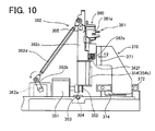
- the perpendicularly oriented empty cassette 3 is pushed to the cassette transport part 330 side (arrow Y2 direction) by the pushing member 371 of the feeding part 370, and is stored in the cassette transport part 330, as shown in Figs. 9 and 10.
- the empty cassettes 3 are sequentially loaded by transporting the cassette transport part 330 in the Y direction via the transport belt 331.
- the stained slide glass 10 which has been moved to the entrance position where it is accessible to the top chuck 415h and bottom chuck 415g of the slide glass take-out part 410 of the sample image obtaining apparatus 400, is removed from the cassette 3 in the slide glass take-out part 410, as shown in Fig. 14.
- the stained slide glass 10 is transported to the reading position of the barcode reading part 420.
- the bottom chuck 415g is moved in the Z direction by extension in the Z direction of the rod 415f of the solenoid 415c and supports the bottom surface of a slide glass 10 in the transport path 400a.
- the top chuck 415h is turned in the arrow C direction together with the support shaft 415e in linkage with the movement of the bottom chuck 415g in the Z direction (upward direction), and supports the bottom surface of the slide glass 10 in the transport path 400a.
- the slide glass 10 is held by the bottom chuck 415g and the top chuck 415h in the transport path 400a.
- the pulley 412 and drive transmission belt 414 are driven by the actuation of the motor 411, and the moving part 415 is moved in the X1 direction in linkage with the drive transmission belt 414. In this way the slide glass 10 gripped by the top chuck 415h and the bottom chuck 415g is transported to the reading position 400c.
- the barcode reading part 420 reads the two-dimensional barcode 10b printed on the frosted region 10a of the slide glass 10 as shown in Fig. 11. Then, the specimen number of the stained slide glass 10 read by the barcode reading part 420 is sent to the control part 404a of the personal computer 400. Accordingly, the two-dimensional barcode 10b of the slide glass 10 can be read at a position directly before imaging by the imaging part 430. Thereafter, the stained slide glass 10, which has been read by the barcode reading part 420, is pushed by the pressure part 415i of the slide glass take-out part 410 and moved in the X1 direction along the transport path 400a. In this way the stained slide glass 10 is transported to the feed position 400d at which it is accessible to the slide chuck 431.
- the slide chuck 431 is moved backward and drawn into the imaging part 430. In this way the slide glass 10 is positioned below the objective lens 432.
- An image of the sample on the slide glass 10 gripped by the slide chuck 431 is obtained by the CCD camera 435 of the imaging part 430 through the plurality of lenses 433 and the half mirror 434.
- a plurality of images are obtained from the sample of the slide glass 10 (refer to Fig. 15).
- the sample images obtained by the CCD camera 435 of the imaging part 430 are sent to the control part 404a of the personal computer 404.
- the two-dimensional barcode 10b read by the barcode reading part 420 is associated with the sample images obtained by the CCD camera 435 of the imaging part 420, and the data are stored in the memory 404d of the control part 404a (refer to Fig. 2).
- the smear slide corresponding to the obtained sample images can be easily managed.
- the sample images (refer to Fig. 15) sent to the control part 404a of the personal computer 404 are subjected to image processing and the blood cells are automatically classified.
- the obtained analysis results are sent to the control part 404a of the personal computer 404.
- the two-dimensional barcode 10b read by the barcode reading part 420 is associated with the analysis results, and the data are stored in the memory 404d of the control part 404a.
- the smear slide corresponding to the obtained sample images and the analysis results of the sample can be easily managed.
- the imaged slide glass 10 is returned to the feed position 400d in front of the slide chuck 431, and thereafter pushed by the pushing part 415j of the slide glass take-out part 410 so as to be transported along the transport path 400a, as shown in Fig. 14. Thereafter, the empty magazine 450 (refer to Fig. 12) is transported upward from the magazine storage part 441 of the magazine transport part 440, and the slide glass 10 is housed in the first storage part 451 of the magazine 450, as shown in Fig. 17. Then, the imaged glass slides 10 are sequentially housed in the second storage part 451 and third storage part 451 of the magazine 450.
- the control part 404a of the personal computer 404 controls the number of steps of the motor 443a of the magazine transport part 443.
- the two-dimensional barcode 10b of the slide glass 10 and the position at which the slide glass 10 is housed in the magazine 450 are associated and stored in the memory 404d of the control part 404a.
- the smear slide corresponding to the obtained sample images and the position of the smear slide can be easily managed.
- the analysis operation of the sample image obtaining system is performed in this way in the present embodiment.
- the present embodiment provides the sample image obtaining apparatus 400 with a barcode reading part 420 for reading a two-dimensional barcode 10b on a slide glass 10, imaging part 430 for obtaining an image of a sample smeared on a slide glass 10 the two-dimensional barcode 10b of which has been read, and a memory 404d for storing the two-dimensional barcode read by the barcode reading part 420 and the sample image obtained by the imaging part 430 corresponding to the two-dimensional barcode.
- the image of the sample smeared on the slide glass 10 obtained by the imaging part 430 can be associated with the two-dimensional barcode 10b specifying the slide glass 10.
- the slide glass 10 corresponding to the obtained sample images can be easily managed.
- the personal computer 404 is provided with the memory 404d for storing the two-dimensional barcode 10b read by the barcode reading part 420 and the position of the slide glass 10 within the magazine 450 corresponding to the two-dimensional barcode 10b. Therefore, after the imaging part 430 obtains the image of the sample smeared on the slide glass 10 the barcode 10b of which has already been read, the slide glass 10 can be housed in the storage part 451 of the magazine 450. If the position of the slide glass 10 is stored in the memory 404d at this time, the position of the stored slide glass 10 can be associated with the sample image of the slide glass 10 and the barcode 10b specifying the slide glass 10. As a result, the slide glass 10 corresponding to the obtained sample images and its position can be easily managed.
- the personal computer 404 is provided with a control part 404a for performing sample analysis based on the sample image obtained by the imaging part 430.
- the blood cells can be readily classified based on the sample image.
- the personal computer 404 is provided with the memory 404d for storing the two-dimensional barcode 10b read by the barcode reading part 420 and the analysis results corresponding to the two-dimensional barcode 10b wherein the analysis results is obtained by the analysis performed by the control part 404a.
- the smear slide corresponding to the obtained sample images and the analysis results of the sample can be easily managed.
- the smear slide is housed in a cassette 3 in the blood smear slide preparing apparatus 100
- the cassette supplying part 300 has the function of storing a plurality of cassettes 3 received from the blood smear slide preparing apparatus 100 and the function of transferring the cassettes 3
- the sample image obtaining apparatus 400 is provided with a slide glass take-out part 410 for taking out a smear slide from a cassette 3 that has been transferred by the cassette supplying apparatus 300. Therefore, the cassette 3 housing the smear slide can be accommodated in the cassette supplying apparatus 300, and can be transported to the slide glass take-out part 410.
- the smear slide can be removed from the cassette 3 by the slide glass take-out part 410, and the two-dimensional barcode 10b of the smear slide can be easily read by the barcode reading part 430.
- the smear slide can be transported while housed in the cassette 3 in the blood smear slide preparing apparatus 100, and the two-dimensional barcode 10b of the slide glass can be easily read.
- the blood smear slide preparing apparatus 100 is provided with a keeping part 9 for storing a plurality of cassettes 3, second cassette transport part 8 for transporting cassettes 3 to both the cassette supplying apparatus 300 and the keeping part 9, and a control part 110 for controlling whether the second cassette transport part 8 transports the cassette 3 to the cassette supplying apparatus 300 or to the keeping part 9. Therefore, the destination of the slide glass 10 prepared by the blood smear slide preparing apparatus 100 can be automatically determined. The load on the operator is therefore reduced since the operator need not determine the destination of the slide glass 10.
- the cassette supplying apparatus 300 is provided with a cassette transport part 330 for storing cassettes 3 from which the slide glass 10 has been removed by the slide glass take-out part 410. Therefore, cassettes 3, from which the slide glass 10 has been removed by the slide glass take-out part 410, can be stored. As a result, the operation of removing the cassette 3 is simplified since the operator need not remove the cassette 3 each time a slide glass 10 has been removed from a cassette 3.
- the cassette supplying apparatus 300 is provided with a cassette transport part 320 for storing a plurality of cassettes 3 received from the blood smear slide preparing apparatus 100, and transporting the stored cassette 3.
- a cassette 3 delivered from the blood smear slide preparing apparatus 100 can be easily stored, and transported.
- the sample image obtaining apparatus 400 is provided with a slide glass take-out part 410, barcode reading part 420, and imaging part 430, and the sample image obtaining apparatus 400 has a function for transporting a slide glass 10 taken out by the slide glass take-out part 410 to the imaging part 430.
- the two-dimensional barcode 10b of the slide glass 10 that has been removed from the cassette 3 can easily be read by the barcode reading part 420, and thereafter the image of the slide glass 10 can be obtained by the imaging part 430.
- the present embodiment is provided with a blood smear slide preparing apparatus 100 for preparing a smear slide, sample image obtaining apparatus 400 for obtaining a sample image, and a cassette supplying apparatus 300 for supplying the prepared smear slide to the sample image obtaining apparatus 400. Therefore, a smear slide prepared by the blood smear slide preparing apparatus 100 can be automatically transported to the sample image obtaining apparatus 400. Thus, the operation is automated from the preparation of a smear slide to imaging. As a result, the operation from the preparation of a smear slide to imaging is performed efficiently since the time and labor of the user transporting a prepared smear slide manually to the imaging device are unnecessary.
- the sample image obtaining apparatus 400 is provided with a magazine storage part 441 for storing a plurality of empty magazines 450, a magazine storage part 442 for storing a plurality of magazines 450 containing slide glasses 10, a magazine transport part 443 for transport the empty magazine 450 from the lower magazine storage part 441 to the upper magazine storage part 442, and a magazine feeding part 444 for delivering the magazine 450, which contains slide glasses 10 and was transported upward by the magazine transport part 443, to the magazine storage part 442.
- a plurality of empty magazines 450 for housing imaged slide glasses 10 can be supplied from the magazine storage part 441 accommodating a plurality of empty magazines 450 to the magazine storage part 442, and a plurality of magazines 450 holding imaged slide glasses 10 can be stored to the magazine storage part 442.
- the operation of replenishing the magazines 450 is simplified since the user need not open the door 403 to replenish the magazine 450 each time a magazine 450 for housing an imaged slide glass 10 is supplied to the magazine storage part 442.
- the operation of removing the magazines 450 is simplified since a magazine 450 need not be removed each time a slide glass 10 is housed.
- the cassette transport part 320 of the cassette supplying apparatus 300 is capable of storing approximately 100 individual cassettes 3. Therefore, a cassette 3 prepared by the blood smear slide preparing apparatus 100 can be stored in the cassette transport part 320 even when the processing power of the blood smear slide preparing apparatus 100 differs from the processing power of the sample image obtaining apparatus 400.
- the present invention is applied to a sample image obtaining system that includes a blood smear slide preparing apparatus, cassette supplying apparatus, and sample image obtaining apparatus.
- a sample image obtaining system that includes a blood smear slide preparing apparatus, cassette supplying apparatus, and sample image obtaining apparatus.
- the present invention is not limited to this application inasmuch as the functions of the blood smear slide preparing apparatus, cassette supplying apparatus, and sample image obtaining apparatus may be possessed by a single apparatus.
- the present invention is applied to a sample image obtaining system that includes a blood smear slide preparing apparatus, cassette supplying apparatus, and sample image obtaining apparatus.
- the blood smear slide preparing apparatus may also possess a function for transporting a cassette to the slide glass take-out part of the sample image obtaining apparatus in a sample image obtaining system configured by a blood smear slide preparing apparatus and a sample image obtaining apparatus.
- the sample image obtaining apparatus may also possess a function for receiving a cassette from the blood smear slide preparing apparatus, and transporting the received cassette to the slide glass take-out part provided in the sample image obtaining apparatus.
- the present invention is applied to a sample image obtaining system that includes a blood smear slide preparing apparatus, cassette supplying apparatus, and sample image obtaining apparatus.
- a sample image obtaining system that includes a blood smear slide preparing apparatus, cassette supplying apparatus, and sample image obtaining apparatus.
- the present invention is not limited to this application inasmuch as the present invention is applicable to a stand-alone sample image obtaining apparatus.
- the present invention is not limited to this arrangement inasmuch as the barcode reading part may be provided in the cassette supplying apparatus, and may alternatively be provided in the blood smear slide preparing apparatus. It's preferred that the barcode reading part may be disposed in front of the imaging part so that the barcode reading part can read the barcode on the slide glass just before the image of the sample on the slide glass is obtained by the imaging part.
Abstract
Description
- The present invention relates to a sample image obtaining apparatus, a sample image obtaining system, and a method for obtaining a sample image. The present invention particularly relates to an apparatus, a system, and a method for obtaining an image of a sample smeared on a slide glass.
- A conventional apparatus for automatically classifying blood images by measuring blood smeared on a slide glass using a measuring unit that includes a microscope and the like is disclosed in
Japanese Laid-Open Patent Publication No. 62-153727 Japanese Laid-Open Patent Publication No. 62-153727 - In the apparatus for automatically classifying blood images disclosed in
Japanese Laid-Open Patent Publication No. 62-153727 Japanese Laid-Open Patent Publication No. 62-153727 - A first aspect of the present invention is a sample image obtaining apparatus, comprising: an identification information reader for reading identification information of a sample smeared on a slide glass, the slide glass having the identification information; an image obtainer for obtaining an image of the sample smeared on the slide glass; and a memory for storing the image obtained by the image obtainer and the identification information read by the identification information reader.
- A second aspect of the present invention is a sample image obtaining system, comprising: a sample smearing apparatus for smearing a sample on a slide glass; a sample image obtaining apparatus for obtaining an image of the sample smeared on the slide glass; and a slide glass transferring apparatus for transferring the sample smeared slide glass obtained by the sample smearing apparatus to the sample image obtaining apparatus, wherein the sample image obtaining apparatus comprises an identification information reader for reading identification information of the sample smeared on the slide glass, the slide glass having the identification information; an image obtainer for obtaining the image of the sample smeared on the slide glass; and a memory for storing the image obtained by the image obtainer and the identification information read by the identification information reader.
- A third aspect of the present invention is a sample image obtaining system, comprising: a sample smearing means for smearing a sample on a slide glass; an identification information reading means for reading identification information of the sample smeared on the slide glass, the slide glass having the identification information; a sample image obtaining means for obtaining an image of the sample smeared on the slide glass; a storing means for storing the image obtained by the sample image obtaining means and the identification information read by the identification information reading means; and a slide glass transferring means for transferring the sample smeared slide glass from the sample smearing means to the sample image obtaining means.
- A fourth aspect of the present invention is A method for obtaining a sample image, comprising steps of: (a) smearing a sample on a slide glass; (b) reading identification information of the sample smeared on the slide glass; (c) automatically transferring the sample smeared slide glass to a sample image obtaining position; (d) obtaining an image of the sample smeared slide glass transferred to the sample image obtaining position; and (e) storing the image and the identification information.
-
- Fig. 1 is a perspective view showing the general structure of an embodiment of the sample image obtaining system of the present invention;
- Fig. 2 is a block diagram of the embodiment of the sample image obtaining system shown in Fig. 1;
- Fig. 3 is a plan view of the blood smear slide preparing apparatus of the embodiment of the sample image obtaining system shown in Fig. 1;
- Fig. 4 is an enlarged view of a frosted region of the slide glass used in the embodiment of the sample image obtaining system shown in Fig. 1;
- Figs. 5 and 6 are perspective views of a slide glass and cassette used in the embodiment of the slide preparing and image obtaining system of Fig. 1;
- Fig. 7 is a top view of the cassette supplying apparatus of the embodiment of the slide preparing and image obtaining system of Fig. 1;
- Fig. 8 is an enlarged perspective view of the cassette turning part of the cassette supplying apparatus of the embodiment of the slide preparing and image obtaining system of Fig. 1;
- Fig. 9 is a top view of the cassette turning part of the cassette supplying apparatus of the embodiment of the slide preparing and image obtaining system of Fig. 1;
- Fig. 10 is a side view of the cassette turning part of the cassette supplying apparatus of the embodiment of the slide preparing and image obtaining system of Fig. 1;
- Fig. 11 is a perspective view of the sample image obtaining apparatus of the embodiment of the slide preparing and image obtaining system shown in Fig. 1;
- Fig. 12 is a perspective view of the magazine of the sample image obtaining apparatus of the embodiment of the slide preparing and image obtaining system shown in Fig. 1;
- Fig. 13 is a side view of the sample image obtaining apparatus of the embodiment of the slide preparing and image obtaining system shown in Fig. 1;
- Fig. 14 is a perspective view of the sample image obtaining apparatus of the embodiment of the slide preparing and image obtaining system shown in Fig. 1;
- Fig. 15 is an image of a sample obtained by the imaging part of the sample image obtaining apparatus of the embodiment of the slide preparing and image obtaining system shown in Fig. 1;
- Fig. 16 is a schematic view of the imaging part of the sample image obtaining apparatus of the embodiment of the slide preparing and image obtaining system shown in Fig. 1;
- Fig. 17 is a perspective view of the magazine transport part of the sample image obtaining apparatus of the embodiment of the slide preparing and image obtaining system shown in Fig. 1; and
- Figs. 18 through 20 are perspective views illustrating the operation of the cassette turning part of the embodiment of the sample image obtaining system of Fig. 1.
- The embodiments of the present invention are described hereinafter based on the drawings.
- The structure of an embodiment of the sample image obtaining system of the present invention is first described referring to Figs. 1 through 20.
- As shown in Figs. 1 and 2, the embodiment of the sample image obtaining system of the present invention is configured by a blood smear
slide preparing apparatus 100 for preparing a slide glass on which a blood sample is smeared, rack transportingapparatus 200,cassette supplying apparatus 300, sampleimage obtaining apparatus 400, andhost computer 500. The sample image obtaining system subjects the image of a sample on a slide glass (slide glass 10 in Fig. 4) prepared by the blood smearslide preparing apparatus 100 to digital image processing, and automatically classifies the blood cells. Furthermore, the blood smearslide preparing apparatus 100 prepares two types of smear slides: a smear slide (slide glass) for automatic analysis, a sample on the slide glass can be analyzed by the sampleimage obtaining apparatus 400, and a smear slide (slide glass) for visual inspection, a sample on the slide glass can be analyzed visually. The blood smearslide preparing apparatus 100 has the processing capacity to prepare 120 blood smear slides per hour. - The
rack transporting apparatus 200 is disposed in front of the blood smearslide preparing apparatus 100. The blood smearslide preparing apparatus 100,cassette supplying apparatus 300, and sampleimage obtaining apparatus 400 are aligned side by side. - As shown in Fig. 1, the
rack transporting apparatus 200 is provided to automatically transport asample rack 150holding test tubes 151 containing blood to the blood smearslide preparing apparatus 100. The blood smearslide preparing apparatus 100 includes a touch panel-typedisplay operating part 101,start switch 102,power switch 103, andcover 104. The blood smearslide preparing apparatus 100 is further provided with ahand member 160 for transporting atest tube 151 containing blood from therack supplying apparatus 200 side to the blood smearslide preparing apparatus 100 side. Arubber stopper 151a seals thetest tube 151 containing blood. - As shown in Fig. 3, the blood smear
slide preparing apparatus 100 is provided with a sucking/dispensing part 1, smearingpart 2,resin cassette 3, cassette storage part 4, firstcassette transport part 5, slideglass insertion part 6, stainingpart 7, secondcassette transport part 8, and keepingpart 9. - The sucking/dispensing part 1 functions to both suck the blood from the test tube 151 (refer to Fig. 1) transported to the blood smear
slide preparing apparatus 100 by the hand member 160 (refer to Fig. 1), and to drip the blood onto aslide glass 10. As shown in Fig. 3, the sucking/dispensing part 1 includes a piercer (sucking needle) 1a for sucking the blood from thetest tube 151,pipette 1b for dispensing the blood on aslide glass 10, syringe pump 1c connected to thepiercer 1a andpipette 1b,valve 1d for opening and closing the flow path between thepiercer 1a and syringe pump 1c, and valve 1e for opening and closing the flow path between thepipette 1b and the syringe pump 1c. The sucking/dispensing part 1 functions to both dispense the same blood (sample) on each of twoslide glasses 10, and to adjust the amount of blood to be dispensed for an amount corresponding to a smear slide for automatic analysis and an amount corresponding to a smear slide for visual inspection. - The smearing
part 2 is provided to supply theslide glass 10 to the dispensing/smearingposition 20, smear and dry the dripped blood on theslide glass 10, and print on theslide glass 10. The smearingpart 2 is provided with a slideglass supplying part 2a, slideglass holding part 2b, drawing glass 2c,transport belts fan 2f,printing part 2g, and slideglass transporting part 2h. - The slide
glass supplying part 2a has the function of supplying aslide glasses 10 held in two slideglass holding parts 2b onto atransport belt 2e using a take-out mechanism not shown in the drawing and chuck not shown in the drawing mounted on thetransport belt 2d. Thetransport belt 2e is configured so as to transportslide glasses 10 to the dispensing/smearingposition 20 and thedrying positions slide glass 10, and movable in the lengthwise direction of theslide glass 10, and is thus capable of smearing blood dispensed on theslide glass 10 at the dispensing/smearingposition 20. Thefan 2f is provided to dry the blood smeared on theslide glass 10 transported to thedrying positions - The
printing part 2g is a thermal transfer printer. As shown in Fig. 4, theprinting part 2g is provided to print a two-dimensional barcode 10b that stores sample information such as specimen number, date, reception number, patient name and the like, and to print three lines of text data of a date (07/06/04) 10c, name (Sysmex) 10d, and sample number (BA15617 slide glass 10. The amount of information contained in the two-dimensional barcode in the present embodiment is 50 bytes. - As shown in Fig. 3, the slide
glass transport part 2h is provided to move theslide glass 10 from the end of thetransport belt 2e to theprinting part 2g, and to move the printedslide glass 10 to theslide insertion position 21e into thecassette 3. The slideglass transport part 2h includes a horizontal movingpiece 2i for moving theslide glass 10 in a horizontal direction (direct X in Fig. 3) from the end of thetransport belt 2e to a horizontal position for printing, and a vertical movingpiece 2j for moving theslide glass 10 in a vertical direction to avertical position 21d for printing and aslide insertion position 21e into thecassette 3. - As shown in Figs. 5 and 6, the
resin cassette 3 is configured so as to be capable of accommodating a smearedslide glass 10 and a liquid (staining liquid) used in a staining process. Specifically, thecassette 3 includes a slideglass insertion hole 3a, and a stain sucking/dispensinghole 3b. Moreover, the slideglass insertion hole 3a and a stain sucking/dispensinghole 3b are internally connected. - As shown in Fig. 3, the cassette storage part 4 is provided for carrying the
cassette 3, and includes atransport belt 4a. - As shown in Fig. 3, the first
cassette transport part 5 is provided to transport acassette 3 from the cassette storage part 4 to the slideglass insertion part 6 and stainingpart 7. The firstcassette transport part 5 includes acassette transport member 5a that is movable in the X direction,drive belt 5b for moving thecassette transport member 5a in the X direction, and atransport path 5c for transporting thecassette 3 supplied from the cassette storage part 4. - As shown in Fig. 3, the slide
glass insertion part 6 is provided to insert.the smeared and printedslide glass 10 in the slideglass insertion hole 3a of thecassette 3. The slideglass insertion part 6 includes acassette turning part 6a to maintain acassette 3 in a horizontal disposition for the insertion of aslide glass 10. - As shown in Fig. 3, the
staining part 7 is provided to stain anunstained slide glass 10 by supplying a staining liquid to the stain sucking/dispensinghole 3b of thecassette 3 which has been transported by thecassette transport member 5a. Thestaining part 7 includes a feedingmember 7a for feeding acassette 3 that has been transported by thecassette transport member 5a to a second suction/discharge part 7d of thestaining part 7, atransport belt 7b for transporting thecassette 3 fed from the feedingmember 7a, first through fifth sucking/discharging parts 7c through 7g for supplying and discharging staining liquid to/from thecassette 3, and afan 7h for drying the stainedslide glass 10. - The second
cassette transport part 8 is configured so as to be capable of transporting acassette 3 which accommodates stainedslide glass 10, to both anentrance 300a of thecassette supplying apparatus 300 and anentrance 9a (refer to Fig. 3) of the keepingpart 9 of the blood smearslide preparing apparatus 100. The secondcassette transport part 8 has atransport part 8b mounted on aframe 8a,drive belt 8c for moving thetransport part 8b in the X direction, and atransport path 8d. Thetransport path 8d is provided so as to extend to a position at theentrance 300a of thecassette supplying apparatus 300. Thetransport path 8d forms a passage for the movement of thecassette 3 that is pushed by thetransport path 8b. - As shown in Fig. 3, the keeping
part 9 is provided to store thecassette 3, which contains theslide glass 10 that has been stained by thestaining part 7. The sample on the stainedslide glass 10 delivered to the keepingpart 9 is visually analyzed. A feedingpart 9b andtransport belt 9c are provided in the keepingpart 9. In the present embodiment, the feedingpart 9b is mounted on theframe 8a of the secondcassette transport part 8, and disposed in a region opposite theentrance 9a of the keepingpart 9. The feedingpart 9b is provided to move thecassette 3, which has been transported to theentrance 9a of the keepingpart 9 by the secondcassette transport part 8, to the keepingpart 9 side. - In the present embodiment, a
control part 110 of the blood smearslide preparing apparatus 100 has a function of controlling whether to transport acassette 3 containing astained slide glass 10 to theentrance 9a of the keepingpart 9, or to theentrance 300a of thecassette supplying apparatus 300. Thecontrol part 110 controls the operation of thedrive belt 8c that drives thetransport part 8b of the secondcassette transport part 8, and the operation of thefeeding part 9b of the keepingpart 9. Thecontrol part 110 is provided with amemory 111 for storing sample information such as the conditions under which the sample was prepared. Thecontrol part 110 is connected by a landline or wirelessly to the host computer 500 (refer to Fig. 2) so as to be capable of communication. - As shown in Fig. 7, the
cassette supplying apparatus 300 is provided to transport aslide glass 10 contained in thecassette 3 received at theentrance 300a to the sample image obtaining apparatus 400 (refer to Fig. 1). As shown in Fig. 1, thecassette supplying apparatus 300 includes adisplay part 301,power switch 302, and cover 303. As shown in Fig. 7, thecassette supplying apparatus 300 is configured by afeeding part 310,cassette transport parts cassette turning part 340. - As shown in Fig. 7, the feeding
part 310 is provided to move thecassette 3 that has arrived at theentrance 300a to thecassette transport part 320 side. The feedingpart 310 is configured by a pushingmember 311 for pushing acassette 3 that has entered theentrance 300a, and a direct-drive guide 312 for moving the pushingmember 311 in the arrow Y direction. - As shown in Fig. 7, the
cassette transport part 320 is provided to transport acassette 3, which has been pushed by the pushingmember 311 of thefeeding part 310, to thecassette turning part 340. Thecassette transport part 320 has the function of storing thecassette 3, and is capable of storing approximately 100individual cassettes 3. Furthermore, a cassette containing a smear slide with an urgent specimen (blood), or a cassette containing a smear slide prepared by manually by a technician or prepared by the bloodsmear preparing apparatus 100 of the present embodiment or a different sample preparing apparatus may be directly placed in thecassette transport part 320 from outside. Acassette 3 unrelated to a set sequence may also be placed in the cassette queue by introducing a cassette among thecassettes 3 transported from the blood smearslide preparing apparatus 100. As shown in Fig. 7, thecassette transport part 320 includes a pair oftransport belts 321 for transporting acassette 3 in the arrow Y1 direction. - As shown in Figs. 8 and 9, the
cassette turning part 340 functions to arrange in a horizontal direction acassette 3 that has been transported while disposed in a perpendicular direction. Thus, aslide glass 10 accommodated in acassette 3 can be removed by a slide glass take-out part 410 (refer to Fig. 14; described later) of the sampleimage obtaining apparatus 400. Thecassette turning part 340 is provided with ahorizontal feeding part 350, turningpart 360, and feedingpart 370. - As shown in Fig. 10, the
horizontal feeding part 350 is configured by amotor 351,pulley 352 connected to themotor 351, a pulley (not shown in the drawing) disposed a predetermined distance from thepulley 352,drive transmission belt 353, and movingmember 354 coupled to thedrive transmission belt 353. As shown in Fig. 8, the movingmember 353 is provided with acassette pushing part 354a for pushing the side end of acassette 3 transported by thecassette transport part 320, and a pushingpart 354b for pushing the turningpart 360. Thus, the movingmember 354, which is coupled to thedrive transmission belt 353 and driven by thedrive transmission belt 353, is moved in the X direction via the drive of themotor 351. As a result, acassette 3 can be moved to the turningpart 360 when the pushingpart 354a pushes the side end of thecassette 3 that has been transported by thecassette transport part 320. Therefore, theentire turning part 360 is moved to the sampleimage obtaining apparatus 400 side (X direction) by the pushingpart 354b pushing the turningpart 360. - As shown in Fig. 8, the turning
part 360 functions to turn thecassette 3 in the arrow B direction after thecassette 3 has been turned in the arrow A direction by thehorizontal feeding part 350. That is, thecassette turning part 360 functions to arrange in a horizontal direction aslide glass 10 within thecassette 3 that has been transported while disposed in a perpendicular direction. As shown in Figs. 8 and 20, the turningpart 360 is movable in the X directions, and bends aspring 304 inserted on the shaft mounted on thechassis 300 via the pushing of the pushingpart 354b of thehorizontal feeding part 350. The turningpart 360 includes aprimary turning part 361 and asecondary turning part 362. - The
primary turning part 361 is provided to rotate thecassette 3 transported by thehorizontal feeding part 350 in the arrow A direction to achieve a transverse orientation (refer to Fig. 18). As shown in Figs. 8 and 9, theprimary turning part 361 includes acassette holding part 361a for accommodating thecassette 3, amotor 361b,arm 361c mounted on the shaft of themotor 361b, movingmember 361d mounted on thearm 361c, direct-drive guide 361e for moving the movingpart 361d in the Z direction, andpressure roller 361f mounted on the movingmember 361d. Thecassette holding part 361a is mounted on theshaft 362e so as to be rotatable, and theshaft 362e is mounted on the rotatingmember 362c of thesecondary turning part 362 described later. Thecassette holding part 361a is provided with a contact piece that contacts thepressure roller 361f mounted on the movingmember 361d. Thecassette holding part 361a is further provided with anopening 361h for inserting a pushingmember 371 of thefeeding part 370 described later. - As shown in Figs. 8 through 10, the
secondary turning part 362 is provided to turn thecassette 3, which has been turned in the arrow A direction to a transverse orientation by the primary turning part 361 (refer to Fig. 18) in the arrow B direction to achieve a horizontal orientation (refer to Fig. 19). Thesecondary turning part 362 includes amotor 362a, anarm 362b mounted on the shaft of themotor 362a, a rotatingmember 362c mounted so as to be rotatable on theshaft 305 that is mounted on thechassis 300b, alink lever 362d one end of which is mounted on thearm 362b and the other end of which is mounted on the rotatingmember 362c, ashaft 362e mounted on the rotatingmember 362c, and acoil spring 362f mounted on theshaft 362e. Thecassette holding member 361a of the primaryrotating part 361 is mounted on theshaft 362e so as to be rotatable, and theshaft 362e is mounted on the rotatingmember 362c. Thecoil spring 362f mounted on theshaft 362e functions to exert a force to rotate thecassette holding member 361a in the arrow A direction. Thus, thecassette holding member 361a, which is rotatably mounted on theshaft 362e mounted on the rotatingmember 362c, is rotated in the arrow A direction (refer to Fig. 8) by the force exerted by thecoil spring 362f so as to position thecassette 3 in a transverse orientation (refer to Fig. 18). From the condition shown in Fig. 18, thearm 362b is rotated by actuating themotor 362a of thesecondary turning part 362, such that the rotatingmember 362c and theprimary turning part 361 are rotated in the arrow B direction (refer to Fig. 8) via thelink lever 362d. As a result, thecassette 3 attains a horizontal orientation (refer to Fig. 19). - The feeding
part 370 is provided to move thecassette 3, from which theslide glass 10 has been removed by the slide glass take-outpart 410 of the sampleimage obtaining apparatus 400 described later, to thecassette transport part 330 side. As shown in Figs. 9 and 10, the feedingpart 370 is configured by a pushingmember 371, direct-drive guide 372 for moving the pushingmember 371 in the Y2 direction, anarm 373, andmotor 374. The pushingmember 371 is mounted on the direct-drive guide 372. The direct-drive guide 372 extends along the Y direction. One end of thearm 373 is mounted on the pushingmember 371 and the other end is coupled to the rotating shaft of themotor 374. Thus, one end of thearm 373 is turned via the drive of the actuation of themotor 374 so as to move the pushingmember 371 along the direction in which the direct-drive guide 372 extends (Y direction). - The
cassette transport part 330 has a configuration similar to that of thecassette transport part 320, and is provided to carry an empty cassette from which aslide glass 10 has been removed, and to store theempty cassette 3. As shown in Fig. 7, thecassette transport part 330 is capable of storing approximately 100 individualempty cassettes 3. Thecassette transport part 330 includes a pair oftransport belts 331 for transporting acassette 3 in the arrow Y2 direction. - The sample
image obtaining apparatus 400 has the function of obtaining images of the sample smeared in thesample smearing region 10f (refer to Fig. 4) of the receivedslide glass 10. The sampleimage obtaining apparatus 400 has the processing capability to obtain images of a sample smeared on 90slide glasses 10 per hour. As shown in Fig. 1, the sampleimage obtaining apparatus 400 includes apower switch 401, acover 402 that can open and close, and adoor 403 provided on the side surface of the case so as to be openable and closable. Apersonal computer 404 is connected to the sampleimage obtaining apparatus 400. As shown in Fig. 2, thecontrol part 404a of the personal computer (PC) 404 is connected to thehost computer 500 via a landline or wirelessly so as to be capable of communication. As shown in Fig. 11, the sampleimage obtaining apparatus 400 is provided with a slide glass take-outpart 410,barcode reading part 420, imagingpart 430,magazine transport part 440, andmagazine 450. As shown in Fig. 12, themagazine 450 has a capacity capable of accommodating 25slide glasses 10. Numbers are affixed at positions on the side surface of thestorage part 451 corresponding to theslide glasses number predetermined slide glass 10 within themagazine 450 can be confirmed visually via these numbers. - As shown in Figs. 13 and 14, the slide glass take-out
part 410 has the function of taking out the astained slide glass 10 from acassette 3 that has been horizontally oriented by thecassette turning part 340 of thecassette supplying apparatus 300, and transporting the stainedslide glass 10 to thebarcode reading part 420. Moreover, the slide glass take-outpart 410 functions to move theslide glass 10 in the X direction. The slide glass take-outpart 410 is configured by amotor 411,pulley 412 connected to themotor 411,pulley 413 provided at a predetermined distance from thepulley 412,drive transmission belt 414 installed onpulley 412 andpulley 413, movingpart 415 that moves in conjunction with thedrive transmission belt 414, direct-drive guide (slide rail) 416 for moving the movingpart 415 in the X direction, and twolight shielding sensors 417. Thus, thedrive transmission belt 414 is driven by the actuation of themotor 411 via thepulley 412, and the movingpart 415 connected to thedrive transmission belt 414 is moved in the X direction. - The moving
part 415 is configured by alinkage 415a connected to thedrive transmission belt 414,solenoid support 415b mounted on thelinkage 415a,solenoid 415c supported by thesolenoid support 415b, movingmember 415d that is movable along a direct-drive guide (slide rail) 416 and mounted on thelinkage 415a,support shaft 415e rotatably mounted on the movingpart 415d,bottom chuck 415g that moves in vertical directions (Z directions) together with arod 415f of thesolenoid 415c,top chuck 415h which is mounted on thesupport shaft 415e and turns in the arrow C direction in linkage with thebottom chuck 415g,pressure parts 415i (refer to Fig. 14) and 415j (refer to Fig. 14) mounted on thesupport shaft 415e. Therefore, thebottom chuck 415g is moved in the Z direction by therod 415f of thesolenoid 415c and supports the bottom surface of aslide glass 10 in thetransport path 400a. At this time, thetop chuck 415h is turned in the arrow C direction together with thesupport shaft 415e in linkage with the movement of thebottom chuck 415g in the Z direction (upward direction). The bottom surface of theslide glass 10 is supported in thetransport path 400a. Thus, theslide glass 10 is held between thebottom chuck 415g and thetop chuck 415h in thetransport path 400a. Since thepressure parts support shaft 415e, thepressure parts 415i (refer to Fig. 14) and 415j (refer to Fig. 14) turn in the arrow C direction in linkage with the turning of thetop chuck 415h in the arrow C direction. As shown in Fig. 14, adetection piece 415k is provided on the movingmember 415d to block the light of the twolight shielding sensors 417, such that the position of the movingpart 415 can be detected by the twolight shielding sensors 417. - The
top chuck 415h and thebottom chuck 415g have the functions of holding aslide glass 10 disposed at theentrance position 400b in thetransport path 400a by thecassette turning part 340 of thecassette supplying apparatus 400, and transporting theslide glass 10 in the X1 direction to thereading position 400c of thebarcode reading part 420. Thepressure part 415i has the function of transporting aslide glass 10 in thetransport path 400a by thetop chuck 415h andbottom chuck 415g to afeed position 400d from which theslide glass 10 can be pulled out by theslide chuck 431 of theimaging part 430. Thepressure part 415j has the function of transporting theslide glass 10 disposed at thefeed position 400d in thetransport path 400a to themagazine entrance position 400e in thetransport path 400a. - In the present embodiment, the
barcode reading part 420 is a two-dimensional barcode reader as shown in Fig. 11, and has the function of reading a two-dimensional barcode 10b (refer to Fig. 4) printed on thefrosted region 10a of theslide glass 10. After the two-dimensional barcode 10b has been read, the bottom end of theslide glass 10 is pushed by the pushingpart 415i to transport theslide glass 10 to thefeed position 400d where it can be grabbed by theslide chuck 431 of theimaging part 430. - As shown in Fig. 16, the
imaging part 430 is provided to obtain an image of the sample (refer to Fig. 15) smeared in thesample smearing region 10f (refer to Fig. 4) of theslide glass 10. Theimaging part 430 includes aslide chuck 431,objective lens 432, a plurality oflenses 433,half mirror 434,CCD camera 435, andline sensors 436 through 438. Theslide chuck 431 has the function of moving forward and gripping theslide 10 which has been transported to thefeed position 400d in thetransport path 400a, and thereafter moving downward and disposing theslide glass 10 at a position below theobjective lens 432. Thus, the image of the sample in thesample smear region 10f of theslide glass 10 positioned below theobjective lens 432 is obtained by theCCD camera 435 through the plurality oflenses 433. Theline sensor 436 has the function of detecting white blood cells 600 (refer to Fig. 15 distinctively stained blue. Theline sensors CCD camera 435. - As shown in Fig. 17, the
magazine transport part 440 is configured by amagazine storage part 441 andmagazine storage part 442,magazine transport part 443, andmagazine feeding part 444. Themagazine transport part 440 has the function of transporting anempty magazine 450, which has been supplied by opening the door 403 (refer to Fig. 1) provided in the side surface of the casing so as to be openable, from themagazine storage part 441 to themagazine storage part 442. - In the present embodiment, the
magazine storage part 441 is provided to store a plurality ofempty magazines 450 as shown in Fig. 17. Themagazine storage part 441 includes a pair oftransport belts 441a to transport themagazine 450 in the Y1 direction. Themagazine storage part 442 is provided to store a plurality ofmagazines 450 that containslide glass 10. Themagazine storage parts individual magazines 450. - The
magazine transport part 443 is configured so as to transport anempty magazine 450 from the lowermagazine storage part 441 to the uppermagazine storage part 442. Themagazine transport part 443 includes amotor 443a,pulley 443b connected to the shaft of themotor 443a,pulley 443c disposed above thepulley 443b at a predetermined distance,drive transmission belt 443d installed on thepulley transport member 443e coupled to thedrive transmission belt 443d. Thus, thedrive transmission belt 443d is driven via the actuation of themotor 443a through thepulley 443b. As a result, thetransport member 443e coupled to thedrive transmission belt 443d is moved in the Z direction. Thus, thetransport member 443e holding amagazine 450 can be moved in the Z direction. - The
magazine feeding part 444 has the function of delivering themagazine 450, which contains aslide glass 10 and was transported upward by themagazine transport part 443, to themagazine storage part 442. Themagazine feeding part 444 is configured by a pushingmember 444a,movable slide rail 444b, sliderail support member 444c that movably supports theslide rail 444b,arm 444d, and amotor 444e. The pushingmember 444a is mounted on theslide rail 444b. Theslide rail 444b extends along the Y direction. One end of thearm 444d is mounted on theslide rail 444b through a slot, and the other end is coupled to the rotating shaft of themotor 444e. Thus, one end of thearm 444d is turned via the actuation of themotor 444e, and theside rail 444b is moved in the Y direction relative to the sliderail support member 444c. In this way the pushingmember 444a is moved in the Y direction. Therefore, a magazine, which has been transported upward by themagazine transport part 443, is pushed by the pushingpart 444a and is pushed to themagazine storage part 442 side. - The personal computer (PC) 404 has the functions of performing digital image processing of the image obtained from the stained
slide glass 10, and automatically analyzing the blood cells, as shown in Figs. 1 and 2. Thepersonal computer 404 has acontrol part 404a,display part 404b, andinput part 404c. Thecontrol part 404a has the functions of controlling the operation of theimaging part 430 and slide glass take-outpart 410, and analyzing the sample based on the image of the sample obtained by the imaging part 430 (refer to Fig. 15). Thecontrol part 404a is provided with amemory 404d (refer to Fig. 2) for storing the identification information (two-dimensional barcode 10b) obtained by thebarcode reading part 420 and the image of the sample obtained by theimaging part 430 corresponding to the identification information. Thememory 404d has the function of storing the identification information (two-dimensional barcode 10b) obtained by thebarcode reading part 420 and the position of theslide glass 10 within themagazine 450 corresponding to the identification information. - The operation of the sample image obtaining system of the present embodiment is described below with reference to Figs. 1 through 20.
- First, when performing a sucking/dispensing operation by the blood smear
slide preparing apparatus 100, thestart switch 102 is pressed to start the blood smearslide preparing apparatus 100, as shown in Fig. 1. In this state, asample rack 150accommodating test tube 151 containing a blood sample is placed in therack transporting apparatus 200. Then, an automatic sucking start switch displayed on thedisplay operating part 101 is pressed. Thus, thesample rack 150 is transported to a position accessible to thehand member 160 of the blood smearslide preparing apparatus 100, and thetest tube 150 containing the blood is grabbed by thehand member 160. Thetest tube 151 is lifted by raising thehand member 160. The blood contained in thetest tube 151 is stirred by turning thehand member 160, and thereafter thetest tube 151 is disposed in the sucking/dispensing part 1 as shown in Fig. 3. Thepiercer 1a pierces therubber stopper 151a of thetest tube 151 and suctions the blood. During the suction operation, thevalve 1d is opened (ON) and the valve 1e is closed (OFF). After the suction operation is completed, thevalve 1d is closed (OFF) and the valve 1e is opened (ON). Thereafter, thepipette 1b is moved to the dispensing/smearing position shown in Fig. 3. - Next, a
cassette 3 delivery operation is performed by the cassette storage part 4 as shown in Fig. 3 in parallel with the sucking/dispensing operation. Specifically, acassette 3 is first placed in the cassette storage part 4. Thus, acassette 3 is transported by thefeed belt 4a of the cassette storage part 4 and thereafter disposed in thetransport path 5c. - Then, the
control part 110 of the blood smearslide preparing apparatus 100 obtains sample information from the host computer 500 (refer to Fig. 2). The sample information includes information such as the specimen number of the sample smeared on theslide glass 10, and number of prepared smear slides. The sample information includes information regarding whether slides are prepared as visual smear slides or automatic analysis smear slides, or whether smear slides are prepared as both visual smear slides and automatic analysis smear slides. The sample information also includes information such as whether or not analysis is to be performed by the sampleimage obtaining apparatus 400. Then, the smearing conditions are recalled from a database stored in thecontrol part 110 based on the obtained sample information. The smearing conditions are set beforehand for the preparation of smear slides. For example, the amount of blood to be used, the angle of the drawing glass, moving speed of the drawing glass and the like, are set in accordance with smeared sample that is desired. Thereafter, blood is dripped (dispensed) on theslide glass 10 using apipette 1b based on the recalled smearing conditions. When preparing smear slides for automatic analysis and smear slides for visual inspection, the same blood is dispensed to each of twoslide glasses 10. Then, when preparing the smear slide for automatic analysis, blood is dispensed in an amount corresponding to an automatic analysis smear slide. Then, when preparing the smear slide for visual inspection, blood is dispensed in an amount corresponding to a visual analysis smear slide. - Next, the smearing operation is performed by the smearing
part 2 based on the smearing conditions. The smearing operation performed by the smearingpart 2 is performed in parallel with the sucking/dispensing operation or after the sucking/dispensing operation by the sucking/dispensing part 1. The smearingpart 2 supplies aslide glass 10 to the smearing/dispensingposition 20, as shown in Fig. 3. Blood dripped on theslide glass 10 is smeared and dried, and information is printed on theslide glass 10. Specifically,slide glasses 10, which are held in two slideglass holding parts 2b of the slideglass supplying part 2a, are supplied onto atransport belt 2e via removing part not shown in the drawing and thetransport belts transport belt 2e transports theslide glass 10 to the dispensing/smearing position 20. The operation of transporting theslide glass 10 to the dispensing/smearing position 20 is accomplished before the sucking/dispensing operation. In this state, blood is dripped (dispensed) onto theslide glass 10 using thepipette 1b. - Thereafter, the drawing glass 2c is moved so as to abut the
slide glass 10, and the blood dripped on theslide glass 10 at the dispensing/smearing position 20 is smeared by reciprocally moving the drawing glass 2c in the lengthwise direction of theslide glass 10. The contact angle of the drawing glass 2c on theslide glass 10 and the speed of the reciprocating movement of the drawing glass 2c are adjusted when preparing a smear slide for automatic analysis and when preparing a smear slide for visual inspection at this time. Specifically, this adjustment entails ensuring that the thickness of the sample to be used for automatic analysis is less than the thickness of the sample to be used for visual inspection. Thereafter, the smearedslide glass 10 is transported to thedrying position 21a by thetransport belt 2e. At thedrying position 21a, the blood smeared on theslide glass 10 is dried with cool air by thefan 2f. The cool air drying of theslide glass 10 is performed twice at twoadjacent drying positions slide glass 10 is moved to theprinting part 2g by the slideglass transport part 2h. At theprinting part 2g, a two-dimensional barcode 10b containing sample information such as sample number, date, reception date, patient name and the like, and three lines of text data including the date, kanji characters for patient name and the like, are printed in thefrosted region 10a of theslide glass 10, as shown in Fig. 4. - Next, cassettes 3 (refer to Figs. 3 and 6) disposed in the
transport path 5c are transported one by one to the slideglass insertion part 6 via thecassette transport part 5. That is, thecassette transport member 5a of thecassette transport part 5 pushes and moves the side surface of thecassette 3 such that thecassette 3 is transported to the slideglass insertion part 6. - Then, the smeared
slide glass 10 is inserted in thecassette 3. Thereafter, theslide glass 10 is transported to thestaining part 7 by thecassette transport member 5a and subjected to the staining process. - Specifically, the
cassette 3 is moved from the perpendicular position to a horizontal position (refer to the position indicated by the dashed line in Fig. 3) by turning thecassette turning part 6a in a predetermined direction. Thus, thecassette 3 is placed so that theslide glass 10 can be inserted. In this state, the vertical movingpiece 2j of the smearingpart 2 is advanced and the smearedslide glass 10 is inserted into the slideglass insertion hole 3a of thecassette 3. In this way the smearedslide 10 is inserted in thecassette 3. Subsequently, thecassette 3 is returned to the original perpendicular position by turning thecassette turning part 6a in the opposite direction to the previously mentioned predetermined direction. In thestaining part 7, the smearedslide glass 10 is first lifted from the slideglass insertion hole 3a of thecassette 3 by the first sucking/discharging part 7c, and methanol is dispensed to the stain sucking/dispensinghole 3b of thecassette 3. After the smearedslide glass 10 has been returned to thecassette 3, thecassette 3 holding the smearedslide glass 10 is set one at a time on thetransport belt 7b by the feedingmember 7a. Then, thecassette 3 is transported to the second sucking/dispensing part 7d by thetransport belt 7b. - In the second sucking/discharge part 7d, the smeared
slide glass 10 is first lifted from the slideglass insertion hole 3a of thecassette 3. Then, the smeared blood on theslide glass 10 is dried by evaporating the moisture content on the slide surface via an air flow from thefan 7h directed to the sample smearing region of theslide glass 10 for approximately 1 to 60 seconds. Approximately 20 to 120 seconds elapses during the time the smearedslide glass 10 is immersed in the methanol by the first sucking/discharge part 7c until theslide glass 10 is lifted by the second sucking/discharge part 7d (immersion time). - The staining process (May-Grunwald/Giemsa double staining) is performed next. In the second sucking/discharge part 7d, after the methanol is suctioned from the stain sucking/dispensing
hole 3b of thecassette 3, theslide glass 10 is returned to the slideglass insertion hole 3a of thecassette 3. Then, May-Grunwald stain (99% methanol) is dispensed from the stain sucking/dispensinghole 3b of thecassette 3, and the smearedslide glass 10 is immersed in the May-Grunwald stain. Thus, the May-Grunwald/Giemsa double staining process is started. The smearedslide glass 10 is subjected to the staining process, immersion in the May-Grunwald stain, for approximately 1 to 5 minutes while thecassette 3 is transported by thetransport belt 7b. After the May-Grunwald stain has been discharged from the stain sucking/dispensinghole 3b of thecassette 3 by the third sucking/discharge part 7e, diluted May-Grunwald stain is dispensed to the stain sucking/dispensinghole 3b of thecassette 3. The smearedslide glass 10 is immersed in the diluted May-Grunwald stain, for approximately 1 to 5 minutes while thecassette 3 is transported by thetransport belt 7b. After the diluted May-Grunwald stain has been discharged from the stain sucking/dispensinghole 3b of thecassette 3 by the fourth sucking/discharge part 7f, diluted Giemsa stain is dispensed to the stain sucking/dispensinghole 3b of thecassette 3. The smearedslide glass 10 is immersed in the diluted Giemsa stain, for approximately 1 to 20 minutes while thecassette 3 is transported by thetransport belt 7b. - After the diluted Giemsa stain has been discharged from the stain sucking/dispensing
hole 3b of thecassette 3 by the fifth sucking/discharge part 7g, washing solution is dispensed to the stain sucking/dispensinghole 3b of thecassette 3 and the stainedslide glass 10 is rinsed. Thereafter, the stainedslide glass 10 is dried by thefan 7h. - In the present embodiment, the
control part 110 determines the transport destination of acassette 3 holding astained slide glass 10 transported by thetransport belt 7b of thestaining part 7 based on the sample information. That is, thecontrol part 110 determines whether thecassette 3 should be transported to theentrance 9a (refer to Fig. 7) of the keepingpart 9 of the blood smearslide preparing apparatus 100 or theentrance 300a (refer to Fig. 7) of thecassette supplying apparatus 300. - The
cassette 3 holding the stainedslide glass 10 is transported to the determined destination by the secondcassette transport part 8 based on the transport destination information determined by thecontrol part 110. Then, thecassette 3, which holds the stainedslide glass 10 transported to theentrance 9a of the keepingpart 9 of the blood smearslide preparing apparatus 100, is moved to the keepingpart 9 side by thetransport part 9b of the keepingpart 9. - On the other hand, a
cassette 3, which holds a stainedslide glass 10 transported to theentrance 300a of thecassette supplying apparatus 300, is pushed to thecassette transport part 320 side by the feedingpart 310, and is stored in thecassette transport part 320. Then, thecassette 3 is transported to the turningpart 340 by thetransport belt 321 of thecassette transport part 320. - The
cassette 3 transported to thecassette turning part 340 is transported in the X1 direction by thetransverse feeding part 350 of thecassette turning part 340, as shown in Figs. 8 and 9. Specifically, the movingmember 354, which is coupled to thedrive transmission belt 353 and driven by thedrive transmission belt 353, is moved in the X1 direction via the drive of themotor 351 and thepulley 352. At this time, a side end of thecassette 3 transported by thecassette transport part 320 is pushed by thecassette pushing part 354a such that thecassette 3 is transported to the turningpart 360 side so as to be held by thecassette holding member 361a of thecassette turning part 360. - The
cassette 3 held by thecassette holding member 361a of the turningpart 360, is turned in the arrow A direction by thefirst turning part 361, as shown in Fig. 18. Specifically, thearm 361c is turned by themotor 361b, and the movingmember 361d is moved in the Z direction (downward). At this time, thecassette holding member 361a is forced in the arrow A direction by thecoil spring 362f mounted on theshaft 362e of thesecond turning part 362. Therefore, thecassette holding part 361a is turned in the arrow A direction on theshaft 362e while supported by thepressure roller 361f of the movingmember 361d. - As shown in Fig. 19, the
first turning part 361 and thecassette 3 that has been turned in the arrow A direction (refer to Fig. 18) by thefirst turning part 361 are turned in the arrow B direction by thesecond turning part 362 such that thecassette 3 and theslide glass 10 within thecassette 3 are disposed in a horizontal direction. Specifically, thearm 362b is turned by the actuation of themotor 362a, and the turningmember 362c and thefirst turning part 361 are turned in the arrow B direction on the shaft 305 (refer to Fig. 8) via thelink lever 362d. - As shown in Fig. 20, when the
second turning part 362 has been turned in the arrow B direction (refer to Fig. 19), thetransverse feeding part 350 is turned in the X1 direction to move the turningpart 340, which includes thefirst turning part 361 andsecond turning part 362, in the X1 direction. That is, thecassette turning part 340 is moved in the X1 direction while the spring on the shaft is contracted by thetransverse feeding part 350 moving in the X1 direction. Thus, theslide glass 10 protrudes from theopening 303a (refer to Figs. 1 and 7) provided in the side surface of thecover 303, and is fed to theentrance position 400b where theslide glass 10 is accessible to thetop chuck 415h andbottom chuck 415g of the slide glass take-outpart 410 of the sampleimage obtaining apparatus 400 as shown in Fig. 13. - The
cassette 3, from which theslide glass 10 has been removed by thetop chuck 415h andbottom chuck 415g of the slide glass take-outpart 410 of the sampleimage obtaining apparatus 400, is re-disposed from the horizontal orientation (refer to Fig. 20) to a perpendicular orientation (refer to Fig. 8) by reversing the operation of the previously described operation by thefirst turning part 361 andsecond turning part 362. The perpendicularly orientedempty cassette 3 is pushed to thecassette transport part 330 side (arrow Y2 direction) by the pushingmember 371 of thefeeding part 370, and is stored in thecassette transport part 330, as shown in Figs. 9 and 10. Theempty cassettes 3 are sequentially loaded by transporting thecassette transport part 330 in the Y direction via thetransport belt 331. - Then, the stained
slide glass 10, which has been moved to the entrance position where it is accessible to thetop chuck 415h andbottom chuck 415g of the slide glass take-outpart 410 of the sampleimage obtaining apparatus 400, is removed from thecassette 3 in the slide glass take-outpart 410, as shown in Fig. 14. The stainedslide glass 10 is transported to the reading position of thebarcode reading part 420. Specifically, thebottom chuck 415g is moved in the Z direction by extension in the Z direction of therod 415f of thesolenoid 415c and supports the bottom surface of aslide glass 10 in thetransport path 400a. At this time, thetop chuck 415h is turned in the arrow C direction together with thesupport shaft 415e in linkage with the movement of thebottom chuck 415g in the Z direction (upward direction), and supports the bottom surface of theslide glass 10 in thetransport path 400a. Thus, theslide glass 10 is held by thebottom chuck 415g and thetop chuck 415h in thetransport path 400a. When theslide glass 10 is gripped by the top and bottom chucks, thepulley 412 and drivetransmission belt 414 are driven by the actuation of themotor 411, and the movingpart 415 is moved in the X1 direction in linkage with thedrive transmission belt 414. In this way theslide glass 10 gripped by thetop chuck 415h and thebottom chuck 415g is transported to thereading position 400c. - The
barcode reading part 420 reads the two-dimensional barcode 10b printed on thefrosted region 10a of theslide glass 10 as shown in Fig. 11. Then, the specimen number of the stainedslide glass 10 read by thebarcode reading part 420 is sent to thecontrol part 404a of thepersonal computer 400. Accordingly, the two-dimensional barcode 10b of theslide glass 10 can be read at a position directly before imaging by theimaging part 430. Thereafter, the stainedslide glass 10, which has been read by thebarcode reading part 420, is pushed by thepressure part 415i of the slide glass take-outpart 410 and moved in the X1 direction along thetransport path 400a. In this way the stainedslide glass 10 is transported to thefeed position 400d at which it is accessible to theslide chuck 431. - As shown in Fig. 16, after the
slide glass 10 disposed at thefeed position 400d has been gripped by theslide chuck 431 that has been moved forward, theslide chuck 431 is moved backward and drawn into theimaging part 430. In this way theslide glass 10 is positioned below theobjective lens 432. An image of the sample on theslide glass 10 gripped by theslide chuck 431 is obtained by theCCD camera 435 of theimaging part 430 through the plurality oflenses 433 and thehalf mirror 434. Thus, a plurality of images are obtained from the sample of the slide glass 10 (refer to Fig. 15). Thereafter, the sample images obtained by theCCD camera 435 of theimaging part 430 are sent to thecontrol part 404a of thepersonal computer 404. As a result, the two-dimensional barcode 10b read by thebarcode reading part 420 is associated with the sample images obtained by theCCD camera 435 of theimaging part 420, and the data are stored in thememory 404d of thecontrol part 404a (refer to Fig. 2). Thus, the smear slide corresponding to the obtained sample images can be easily managed. - The sample images (refer to Fig. 15) sent to the
control part 404a of thepersonal computer 404 are subjected to image processing and the blood cells are automatically classified. The obtained analysis results are sent to thecontrol part 404a of thepersonal computer 404. As a result, the two-dimensional barcode 10b read by thebarcode reading part 420 is associated with the analysis results, and the data are stored in thememory 404d of thecontrol part 404a. Thus, the smear slide corresponding to the obtained sample images and the analysis results of the sample can be easily managed. - The imaged
slide glass 10 is returned to thefeed position 400d in front of theslide chuck 431, and thereafter pushed by the pushingpart 415j of the slide glass take-outpart 410 so as to be transported along thetransport path 400a, as shown in Fig. 14. Thereafter, the empty magazine 450 (refer to Fig. 12) is transported upward from themagazine storage part 441 of themagazine transport part 440, and theslide glass 10 is housed in thefirst storage part 451 of themagazine 450, as shown in Fig. 17. Then, the imaged glass slides 10 are sequentially housed in thesecond storage part 451 andthird storage part 451 of themagazine 450. Thecontrol part 404a of thepersonal computer 404 controls the number of steps of themotor 443a of themagazine transport part 443. Accordingly, the two-dimensional barcode 10b of theslide glass 10 and the position at which theslide glass 10 is housed in themagazine 450 are associated and stored in thememory 404d of thecontrol part 404a. Thus, the smear slide corresponding to the obtained sample images and the position of the smear slide can be easily managed. The analysis operation of the sample image obtaining system is performed in this way in the present embodiment. - As the described above, the present embodiment provides the sample
image obtaining apparatus 400 with abarcode reading part 420 for reading a two-dimensional barcode 10b on aslide glass 10,imaging part 430 for obtaining an image of a sample smeared on aslide glass 10 the two-dimensional barcode 10b of which has been read, and amemory 404d for storing the two-dimensional barcode read by thebarcode reading part 420 and the sample image obtained by theimaging part 430 corresponding to the two-dimensional barcode. Thus, the image of the sample smeared on theslide glass 10 obtained by theimaging part 430 can be associated with the two-dimensional barcode 10b specifying theslide glass 10. As a result, theslide glass 10 corresponding to the obtained sample images can be easily managed. - In the present embodiment, the
personal computer 404 is provided with thememory 404d for storing the two-dimensional barcode 10b read by thebarcode reading part 420 and the position of theslide glass 10 within themagazine 450 corresponding to the two-dimensional barcode 10b. Therefore, after theimaging part 430 obtains the image of the sample smeared on theslide glass 10 thebarcode 10b of which has already been read, theslide glass 10 can be housed in thestorage part 451 of themagazine 450. If the position of theslide glass 10 is stored in thememory 404d at this time, the position of the storedslide glass 10 can be associated with the sample image of theslide glass 10 and thebarcode 10b specifying theslide glass 10. As a result, theslide glass 10 corresponding to the obtained sample images and its position can be easily managed. - In the present embodiment, the
personal computer 404 is provided with acontrol part 404a for performing sample analysis based on the sample image obtained by theimaging part 430. Thus, the blood cells can be readily classified based on the sample image. - In the present embodiment, the
personal computer 404 is provided with thememory 404d for storing the two-dimensional barcode 10b read by thebarcode reading part 420 and the analysis results corresponding to the two-dimensional barcode 10b wherein the analysis results is obtained by the analysis performed by thecontrol part 404a. Thus, the smear slide corresponding to the obtained sample images and the analysis results of the sample can be easily managed. - In the present embodiment, the smear slide is housed in a
cassette 3 in the blood smearslide preparing apparatus 100, thecassette supplying part 300 has the function of storing a plurality ofcassettes 3 received from the blood smearslide preparing apparatus 100 and the function of transferring thecassettes 3, and the sampleimage obtaining apparatus 400 is provided with a slide glass take-outpart 410 for taking out a smear slide from acassette 3 that has been transferred by thecassette supplying apparatus 300. Therefore, thecassette 3 housing the smear slide can be accommodated in thecassette supplying apparatus 300, and can be transported to the slide glass take-outpart 410. Then, the smear slide can be removed from thecassette 3 by the slide glass take-outpart 410, and the two-dimensional barcode 10b of the smear slide can be easily read by thebarcode reading part 430. As a result, the smear slide can be transported while housed in thecassette 3 in the blood smearslide preparing apparatus 100, and the two-dimensional barcode 10b of the slide glass can be easily read. - In the present embodiment, the blood smear
slide preparing apparatus 100 is provided with a keepingpart 9 for storing a plurality ofcassettes 3, secondcassette transport part 8 for transportingcassettes 3 to both thecassette supplying apparatus 300 and the keepingpart 9, and acontrol part 110 for controlling whether the secondcassette transport part 8 transports thecassette 3 to thecassette supplying apparatus 300 or to the keepingpart 9. Therefore, the destination of theslide glass 10 prepared by the blood smearslide preparing apparatus 100 can be automatically determined. The load on the operator is therefore reduced since the operator need not determine the destination of theslide glass 10. - In the present embodiment, the
cassette supplying apparatus 300 is provided with acassette transport part 330 for storingcassettes 3 from which theslide glass 10 has been removed by the slide glass take-outpart 410. Therefore,cassettes 3, from which theslide glass 10 has been removed by the slide glass take-outpart 410, can be stored. As a result, the operation of removing thecassette 3 is simplified since the operator need not remove thecassette 3 each time aslide glass 10 has been removed from acassette 3. - In the present embodiment, the
cassette supplying apparatus 300 is provided with acassette transport part 320 for storing a plurality ofcassettes 3 received from the blood smearslide preparing apparatus 100, and transporting the storedcassette 3. Thus, acassette 3 delivered from the blood smearslide preparing apparatus 100 can be easily stored, and transported. - In the present embodiment, the sample
image obtaining apparatus 400 is provided with a slide glass take-outpart 410,barcode reading part 420, andimaging part 430, and the sampleimage obtaining apparatus 400 has a function for transporting aslide glass 10 taken out by the slide glass take-outpart 410 to theimaging part 430. Thus, the two-dimensional barcode 10b of theslide glass 10 that has been removed from thecassette 3 can easily be read by thebarcode reading part 420, and thereafter the image of theslide glass 10 can be obtained by theimaging part 430. - The present embodiment is provided with a blood smear
slide preparing apparatus 100 for preparing a smear slide, sampleimage obtaining apparatus 400 for obtaining a sample image, and acassette supplying apparatus 300 for supplying the prepared smear slide to the sampleimage obtaining apparatus 400. Therefore, a smear slide prepared by the blood smearslide preparing apparatus 100 can be automatically transported to the sampleimage obtaining apparatus 400. Thus, the operation is automated from the preparation of a smear slide to imaging. As a result, the operation from the preparation of a smear slide to imaging is performed efficiently since the time and labor of the user transporting a prepared smear slide manually to the imaging device are unnecessary. - In the present embodiment, the sample
image obtaining apparatus 400 is provided with amagazine storage part 441 for storing a plurality ofempty magazines 450, amagazine storage part 442 for storing a plurality ofmagazines 450 containingslide glasses 10, amagazine transport part 443 for transport theempty magazine 450 from the lowermagazine storage part 441 to the uppermagazine storage part 442, and amagazine feeding part 444 for delivering themagazine 450, which containsslide glasses 10 and was transported upward by themagazine transport part 443, to themagazine storage part 442. Therefore, a plurality ofempty magazines 450 for housing imagedslide glasses 10 can be supplied from themagazine storage part 441 accommodating a plurality ofempty magazines 450 to themagazine storage part 442, and a plurality ofmagazines 450 holding imagedslide glasses 10 can be stored to themagazine storage part 442. As a result, the operation of replenishing themagazines 450 is simplified since the user need not open thedoor 403 to replenish themagazine 450 each time amagazine 450 for housing an imagedslide glass 10 is supplied to themagazine storage part 442. Furthermore, the operation of removing themagazines 450 is simplified since amagazine 450 need not be removed each time aslide glass 10 is housed. - In the present embodiment, the
cassette transport part 320 of thecassette supplying apparatus 300 is capable of storing approximately 100individual cassettes 3. Therefore, acassette 3 prepared by the blood smearslide preparing apparatus 100 can be stored in thecassette transport part 320 even when the processing power of the blood smearslide preparing apparatus 100 differs from the processing power of the sampleimage obtaining apparatus 400. - The embodiment disclosed herein is in all aspects simply an example and not to be considered limiting in any way. The scope of the present invention is defined in the scope of the claims and not by the description of the embodiment, and further includes all modifications, meanings and equivalences that fall within the scope of the claims.
- For example, in the example of the embodiment described above, the present invention is applied to a sample image obtaining system that includes a blood smear slide preparing apparatus, cassette supplying apparatus, and sample image obtaining apparatus. However, the present invention is not limited to this application inasmuch as the functions of the blood smear slide preparing apparatus, cassette supplying apparatus, and sample image obtaining apparatus may be possessed by a single apparatus.
- Furthermore, in the example of the embodiment described above, the present invention is applied to a sample image obtaining system that includes a blood smear slide preparing apparatus, cassette supplying apparatus, and sample image obtaining apparatus. However, the present invention is not limited to this application inasmuch as the blood smear slide preparing apparatus may also possess a function for transporting a cassette to the slide glass take-out part of the sample image obtaining apparatus in a sample image obtaining system configured by a blood smear slide preparing apparatus and a sample image obtaining apparatus. Furthermore, the sample image obtaining apparatus may also possess a function for receiving a cassette from the blood smear slide preparing apparatus, and transporting the received cassette to the slide glass take-out part provided in the sample image obtaining apparatus.
- Furthermore, in the example of the embodiment described above, the present invention is applied to a sample image obtaining system that includes a blood smear slide preparing apparatus, cassette supplying apparatus, and sample image obtaining apparatus. However, the present invention is not limited to this application inasmuch as the present invention is applicable to a stand-alone sample image obtaining apparatus.
- The above embodiment has been described in terms of a sample image obtaining apparatus provided with a barcode reading part. However, the present invention is not limited to this arrangement inasmuch as the barcode reading part may be provided in the cassette supplying apparatus, and may alternatively be provided in the blood smear slide preparing apparatus. It's preferred that the barcode reading part may be disposed in front of the imaging part so that the barcode reading part can read the barcode on the slide glass just before the image of the sample on the slide glass is obtained by the imaging part.
Claims (18)
- A sample image obtaining apparatus, comprising:an identification information reader for reading identification information of a sample smeared on a slide glass, the slide glass having the identification information;an image obtainer for obtaining an image of the sample smeared on the slide glass; anda memory for storing the image obtained by the image obtainer and the identification information read by the identification information reader.
- The sample image obtaining apparatus of claim 1, further comprising
a rack setting section for setting a rack which has a plurality of housing parts for housing the sample smeared slide glass, wherein one of the housing parts houses the sample smeared slide glass after the image of the sample smeared slide glass has been obtained by the image obtainer;
wherein the memory stores a position of the housing part housing the sample smeared slide glass, with the image and the identification information. - The sample image obtaining apparatus of claim 1 or claim 2, further comprising
an analyzer for analyzing the image obtained by the image obtainer. - The sample image obtaining apparatus of claim 3, wherein
the memory stores an analysis result obtained by the analyzer with the image and the identification information. - A sample image obtaining system, comprising:a sample smearing apparatus for smearing a sample on a slide glass;a sample image obtaining apparatus for obtaining an image of the sample smeared on the slide glass; anda slide glass transferring apparatus for transferring the sample smeared slide glass obtained by the sample smearing apparatus to the sample image obtaining apparatus,wherein the sample image obtaining apparatus comprises an identification information reader for reading identification information of the sample smeared on the slide glass, the slide glass having the identification information; an image obtainer for obtaining the image of the sample smeared on the slide glass; and a memory for storing the image obtained by the image obtainer and the identification information read by the identification information reader.
- The sample image obtaining system of claim 5, wherein
the sample smearing apparatus comprises a slide glass inserter for inserting the sample smeared slide glass in a cassette, and
the slide glass transferring apparatus comprises a cassette accommodating section for accommodating the cassette received from the sample smearing apparatus; and a cassette transferring section for transferring the cassette accommodated in the cassette accommodating section to a predetermined position; and
the sample image obtaining apparatus comprises a slide glass take-out part for taking out the sample smeared slide glass from the cassette transferred to the predetermined position. - The sample image obtaining system of claim 6, wherein the sample smearing apparatus comprises
a second cassette accommodating section for accommodating the cassette after the sample smeared slide glass has been inserted in the cassette by the slide glass inserter;
a second cassette transferring section for transferring the cassette to the slide glass transferring apparatus or to the second cassette accommodating section; and
a controller for controlling whether the second cassette transferring section transfers the cassette to the slide glass transferring apparatus or to the second cassette accommodating section. - The sample image obtaining system of claim 6 or claim 7, wherein
the slide glass transferring apparatus comprises a third cassette accommodating section for accommodating the cassette after the sample smeared slide glass has been taken out from the cassette by the slide glass take-out part. - The sample image obtaining system of any one of claim 6 to 8, wherein
the sample image obtaining apparatus comprises a slide glass transferring section for transferring the sample smeared slide glass taken out by the slide glass take-out part to the image obtainer. - A sample image obtaining system, comprising:a sample smearing means for smearing a sample on a slide glass;an identification information reading means for reading identification information of the sample smeared on the slide glass, the slide glass having the identification information;a sample image obtaining means for obtaining an image of the sample smeared on the slide glass;a storing means for storing the image obtained by the sample image obtaining means and the identification information read by the identification information reading means; anda slide glass transferring means for transferring the sample smeared slide glass from the sample smearing means to the sample image obtaining means.
- The sample image obtaining system of claim 10, wherein
the sample smearing means comprises the identification information reading means. - The sample image obtaining system of claim 10, wherein
the slide glass transferring means comprises the identification information reading means. - The sample image obtaining system of any one of claim 10 to 12, further comprising
a first rack setting means for setting a rack;
a first rack transferring means for transferring the rack to a predetermined position;
a slide glass inserting means for inserting the sample smeared slide glass in the rack transferred to the predetermined position after the image of the sample smeared slide glass has been obtained by the sample image obtaining means;
a second rack setting means for setting the rack after the sample smeared slide glass has been inserted in the rack by the slide glass inserting means; and
a second rack transferring means for transferring the rack after the sample smeared slide glass has been inserted in the rack by the slide glass inserting means to the second rack setting means. - A method for obtaining a sample image, comprising steps of:(a) smearing a sample on a slide glass;(b) reading identification information of the sample smeared on the slide glass;(c) automatically transferring the sample smeared slide glass to a sample image obtaining position;(d) obtaining an image of the sample smeared slide glass transferred to the sample image obtaining position; and(e) storing the image and the identification information.
- The method of claim 14, further comprising a step (f) of
inserting the sample smeared slide glass in a rack after the image of the sample smeared slide glass has been obtained. - The method of claim 15, wherein the step (e) further stores a position of the sample smeared slide glass in the rack, with the image and the identification information.
- The method of any one of claim 14 to 16, wherein the step (b) is performed while the step (c) is being performed.
- The method of claim 17, wherein the step (c) further comprises the steps of :(i) inserting the sample smeared slide glass in a cassette, and(ii) taking out the sample smeared slide glass from the cassette,and the step (b) is performed after the sample smeared slide glass has been taken out from the cassette.
Applications Claiming Priority (1)
| Application Number | Priority Date | Filing Date | Title |
|---|---|---|---|
| JP2005376863A JP4808492B2 (en) | 2005-12-28 | 2005-12-28 | Specimen Image Imaging Device, Specimen Image Imaging System, and Specimen Slide Supply Device |
Publications (3)
| Publication Number | Publication Date |
|---|---|
| EP1804046A2 true EP1804046A2 (en) | 2007-07-04 |
| EP1804046A3 EP1804046A3 (en) | 2013-02-20 |
| EP1804046B1 EP1804046B1 (en) | 2016-08-03 |
Family
ID=37895875
Family Applications (1)
| Application Number | Title | Priority Date | Filing Date |
|---|---|---|---|
| EP06026837.2A Active EP1804046B1 (en) | 2005-12-28 | 2006-12-22 | Sample image obtaining apparatus, sample image obtaining system, and method for obtaining sample image |
Country Status (3)
| Country | Link |
|---|---|
| US (1) | US7790107B2 (en) |
| EP (1) | EP1804046B1 (en) |
| JP (1) | JP4808492B2 (en) |
Cited By (6)
| Publication number | Priority date | Publication date | Assignee | Title |
|---|---|---|---|---|
| GB2486937A (en) * | 2010-12-29 | 2012-07-04 | Leica Biosystems Nussloch Gmbh | Apparatus and method for sensing and identifying specimen slides |
| US8815537B2 (en) | 2008-04-25 | 2014-08-26 | Roche Diagnostics Hematology, Inc. | Method for determining a complete blood count on a white blood cell differential count |
| US9083857B2 (en) | 2008-04-25 | 2015-07-14 | Roche Diagnostics Hematology, Inc. | Systems and methods for analyzing body fluids |
| CN105092323A (en) * | 2014-04-28 | 2015-11-25 | 深圳迈瑞生物医疗电子股份有限公司 | Method for adjusting blood film characteristics of blood smear pushed by push piece machine |
| CN106289922A (en) * | 2016-08-31 | 2017-01-04 | 宁波华莱斯医疗器械有限公司 | A kind of liquid base cell sheet producing machine |
| US11047791B2 (en) | 2011-06-17 | 2021-06-29 | Roche Diagnostics Hematology, Inc. | Systems and methods for sample display and review |
Families Citing this family (30)
| Publication number | Priority date | Publication date | Assignee | Title |
|---|---|---|---|---|
| WO2008024778A1 (en) * | 2006-08-21 | 2008-02-28 | Anp Technologies, Inc. | Automated self-contained liquid handling and detection system device |
| JP4975599B2 (en) * | 2007-12-17 | 2012-07-11 | シスメックス株式会社 | Specimen preparation apparatus and specimen preparation method |
| US8388891B2 (en) | 2010-12-28 | 2013-03-05 | Sakura Finetek U.S.A., Inc. | Automated system and method of processing biological specimens |
| JP5647913B2 (en) * | 2011-02-03 | 2015-01-07 | シスメックス株式会社 | Sample preparation equipment |
| WO2013101776A2 (en) | 2011-12-28 | 2013-07-04 | Abbott Laboratories | Accelerated wright-giemsa and may-grünwald staining methods |
| US20140065033A1 (en) | 2012-08-31 | 2014-03-06 | Infopia Co., Ltd. | Case for specimen analyzing kit, kit for specimen analyzing, specimen analysis apparatus and control method of specimen analysis apparatus |
| KR101388691B1 (en) | 2012-08-31 | 2014-04-25 | 주식회사 인포피아 | Specimen analysis apparatus |
| KR101388834B1 (en) * | 2012-08-31 | 2014-04-30 | 주식회사 인포피아 | Specimen analysis apparatus |
| JP6009890B2 (en) * | 2012-09-28 | 2016-10-19 | シスメックス株式会社 | Specimen transport device and specimen inspection system |
| JP5995631B2 (en) | 2012-09-28 | 2016-09-21 | シスメックス株式会社 | Specimen conveying apparatus, specimen inspection system, and specimen conveying method |
| JP6016560B2 (en) * | 2012-09-28 | 2016-10-26 | シスメックス株式会社 | Specimen conveying apparatus and specimen imaging system |
| JP5963631B2 (en) * | 2012-09-28 | 2016-08-03 | シスメックス株式会社 | Specimen storage device, specimen storage method, and storage tool |
| KR101538687B1 (en) * | 2013-08-28 | 2015-07-23 | 주식회사 아세테크 | Glass slide positioning system |
| EP3094957A4 (en) * | 2014-01-17 | 2017-09-20 | Campbell, William, Eugene | Methods and systems for slide processing |
| CN111084626B (en) | 2014-01-29 | 2023-07-11 | 贝克顿·迪金森公司 | System and method for ensuring patient medication and fluid delivery at a clinical point of use |
| JP6669658B2 (en) * | 2014-01-29 | 2020-03-18 | ベクトン・ディキンソン・アンド・カンパニーBecton, Dickinson And Company | Systems and methods for collection confirmation and sample tracking during clinical use |
| JP2017513086A (en) * | 2014-01-29 | 2017-05-25 | ベクトン・ディキンソン・アンド・カンパニーBecton, Dickinson And Company | System and method for ensuring dosing and fluid delivery to a patient during clinical use |
| CN111337323A (en) * | 2014-04-28 | 2020-06-26 | 深圳迈瑞生物医疗电子股份有限公司 | Smear preparation device and smear preparation method |
| JP6208301B1 (en) * | 2016-07-29 | 2017-10-04 | シスメックス株式会社 | Specimen transport device, smear sample system, and smear preparation device |
| CN107664703B (en) | 2016-07-29 | 2022-07-08 | 希森美康株式会社 | Specimen transport device, specimen image capturing system, and specimen analysis system |
| JP6205029B1 (en) * | 2016-07-29 | 2017-09-27 | シスメックス株式会社 | Specimen transport apparatus, specimen image imaging system, and specimen analysis system |
| JP6746470B2 (en) * | 2016-11-08 | 2020-08-26 | 日本電子株式会社 | Cartridge holding device |
| JP6889009B2 (en) * | 2017-04-13 | 2021-06-18 | 浜松ホトニクス株式会社 | Image acquisition system and image acquisition method |
| JP7223888B2 (en) * | 2017-07-21 | 2023-02-16 | シスメックス株式会社 | Specimen conveying device and specimen conveying method |
| JP7015654B2 (en) * | 2017-08-10 | 2022-02-03 | シスメックス株式会社 | Inspection system and how to start the inspection system |
| EP3997434A4 (en) * | 2019-07-09 | 2023-07-26 | The Regents of the University of California | Automated rapid on-site evaluation machine and stain |
| JP7236358B2 (en) | 2019-09-04 | 2023-03-09 | 平田機工株式会社 | Specimen preparation device |
| CN115244378A (en) * | 2020-03-31 | 2022-10-25 | 深圳迈瑞生物医疗电子股份有限公司 | Sample processing system, sample processing method, control system, and cell image analysis device |
| CN112525800B (en) * | 2020-12-24 | 2022-09-09 | 仙桃市泰晨防护用品有限公司 | Non-woven fabrics gauze mask gas permeability check out test set |
| KR102368128B1 (en) * | 2021-08-30 | 2022-02-28 | 주식회사 성진전자 | Cassette magazine supply circulation device for printed circuit board vision inspection device |
Citations (10)
| Publication number | Priority date | Publication date | Assignee | Title |
|---|---|---|---|---|
| US3851972A (en) * | 1973-10-18 | 1974-12-03 | Coulter Electronics | Automatic method and system for analysis and review of a plurality of stored slides |
| US4761075A (en) * | 1985-12-10 | 1988-08-02 | Hitachi, Ltd. | Cellular analysis system |
| EP0417006A2 (en) * | 1989-09-06 | 1991-03-13 | Toa Medical Electronics Co., Ltd. | Synthetic apparatus for inspection of blood |
| US5690892A (en) * | 1995-09-15 | 1997-11-25 | Accumed, Inc. | Cassette for use with automated specimen handling system |
| WO2001004828A1 (en) * | 1999-07-13 | 2001-01-18 | Chromavision Medical Systems, Inc. | Automated detection of objects in a biological sample |
| EP1271125A2 (en) * | 2001-06-29 | 2003-01-02 | Sysmex Corporation | Automatic smear preparing apparatus and automatic sample analysis system having the same |
| US20030081209A1 (en) * | 2001-10-26 | 2003-05-01 | Satoshi Takahashi | Apparatus and method for measuring micro area in specimen |
| WO2003106157A2 (en) * | 2002-06-14 | 2003-12-24 | Chromavision Medical Systems, Inc. | Automated slide staining apparatus |
| WO2004059441A2 (en) * | 2002-12-20 | 2004-07-15 | Dakocytomation Denmark A/S | Information notification sample processing system and methods of biological slide processing |
| EP1612537A2 (en) * | 2004-06-30 | 2006-01-04 | Sysmex Corporation | Specimen preparation apparatus, specimen preparation/analysis system and specimen plate |
Family Cites Families (6)
| Publication number | Priority date | Publication date | Assignee | Title |
|---|---|---|---|---|
| JPS62153727A (en) | 1985-12-27 | 1987-07-08 | Hitachi Ltd | Apparatus for automatically classifying blood image |
| JPH04291157A (en) * | 1991-03-20 | 1992-10-15 | Hitachi Ltd | Specimen making apparatus |
| JP3047571B2 (en) * | 1991-11-20 | 2000-05-29 | 株式会社日立製作所 | Clinical test equipment |
| WO2001031868A1 (en) * | 1999-10-28 | 2001-05-03 | The National University Of Singapore | Method and apparatus for communication using pulse decoding |
| US6673315B2 (en) * | 2001-06-29 | 2004-01-06 | Biomachines, Inc. | Method and apparatus for accessing a site on a biological substrate |
| JP2005345229A (en) * | 2004-06-02 | 2005-12-15 | Sysmex Corp | Sample preparation device |
-
2005
- 2005-12-28 JP JP2005376863A patent/JP4808492B2/en active Active
-
2006
- 2006-12-22 EP EP06026837.2A patent/EP1804046B1/en active Active
- 2006-12-28 US US11/646,862 patent/US7790107B2/en active Active
Patent Citations (10)
| Publication number | Priority date | Publication date | Assignee | Title |
|---|---|---|---|---|
| US3851972A (en) * | 1973-10-18 | 1974-12-03 | Coulter Electronics | Automatic method and system for analysis and review of a plurality of stored slides |
| US4761075A (en) * | 1985-12-10 | 1988-08-02 | Hitachi, Ltd. | Cellular analysis system |
| EP0417006A2 (en) * | 1989-09-06 | 1991-03-13 | Toa Medical Electronics Co., Ltd. | Synthetic apparatus for inspection of blood |
| US5690892A (en) * | 1995-09-15 | 1997-11-25 | Accumed, Inc. | Cassette for use with automated specimen handling system |
| WO2001004828A1 (en) * | 1999-07-13 | 2001-01-18 | Chromavision Medical Systems, Inc. | Automated detection of objects in a biological sample |
| EP1271125A2 (en) * | 2001-06-29 | 2003-01-02 | Sysmex Corporation | Automatic smear preparing apparatus and automatic sample analysis system having the same |
| US20030081209A1 (en) * | 2001-10-26 | 2003-05-01 | Satoshi Takahashi | Apparatus and method for measuring micro area in specimen |
| WO2003106157A2 (en) * | 2002-06-14 | 2003-12-24 | Chromavision Medical Systems, Inc. | Automated slide staining apparatus |
| WO2004059441A2 (en) * | 2002-12-20 | 2004-07-15 | Dakocytomation Denmark A/S | Information notification sample processing system and methods of biological slide processing |
| EP1612537A2 (en) * | 2004-06-30 | 2006-01-04 | Sysmex Corporation | Specimen preparation apparatus, specimen preparation/analysis system and specimen plate |
Cited By (14)
| Publication number | Priority date | Publication date | Assignee | Title |
|---|---|---|---|---|
| US10764538B2 (en) | 2008-04-25 | 2020-09-01 | Roche Diagnostics Hematology, Inc. | Systems and methods for analyzing body fluids |
| US8815537B2 (en) | 2008-04-25 | 2014-08-26 | Roche Diagnostics Hematology, Inc. | Method for determining a complete blood count on a white blood cell differential count |
| US9017610B2 (en) | 2008-04-25 | 2015-04-28 | Roche Diagnostics Hematology, Inc. | Method of determining a complete blood count and a white blood cell differential count |
| US9083857B2 (en) | 2008-04-25 | 2015-07-14 | Roche Diagnostics Hematology, Inc. | Systems and methods for analyzing body fluids |
| US9217695B2 (en) | 2008-04-25 | 2015-12-22 | Roche Diagnostics Hematology, Inc. | Method for determining a complete blood count on a white blood cell differential count |
| US10094764B2 (en) | 2008-04-25 | 2018-10-09 | Roche Diagnostics Hematology, Inc. | Systems and methods for determining a complete blood count and a white blood cell differential count |
| GB2486937B (en) * | 2010-12-29 | 2013-03-20 | Leica Biosystems Nussloch Gmbh | Apparatus and method for sensing and identifying specimen slides |
| US8722412B2 (en) | 2010-12-29 | 2014-05-13 | Leica Biosystems Nussloch Gmbh | Identification system for specimen slides |
| GB2486937A (en) * | 2010-12-29 | 2012-07-04 | Leica Biosystems Nussloch Gmbh | Apparatus and method for sensing and identifying specimen slides |
| US11933711B2 (en) | 2011-06-17 | 2024-03-19 | Roche Diagnostics Hematology, Inc. | Systems and methods for sample display and review |
| US11047791B2 (en) | 2011-06-17 | 2021-06-29 | Roche Diagnostics Hematology, Inc. | Systems and methods for sample display and review |
| CN105092323A (en) * | 2014-04-28 | 2015-11-25 | 深圳迈瑞生物医疗电子股份有限公司 | Method for adjusting blood film characteristics of blood smear pushed by push piece machine |
| CN105092323B (en) * | 2014-04-28 | 2018-03-13 | 深圳迈瑞生物医疗电子股份有限公司 | A kind of blood film characterization method for adjusting sheet pushing machine and releasing blood film |
| CN106289922A (en) * | 2016-08-31 | 2017-01-04 | 宁波华莱斯医疗器械有限公司 | A kind of liquid base cell sheet producing machine |
Also Published As
| Publication number | Publication date |
|---|---|
| JP2007178251A (en) | 2007-07-12 |
| US7790107B2 (en) | 2010-09-07 |
| EP1804046B1 (en) | 2016-08-03 |
| US20070148046A1 (en) | 2007-06-28 |
| JP4808492B2 (en) | 2011-11-02 |
| EP1804046A3 (en) | 2013-02-20 |
Similar Documents
| Publication | Publication Date | Title |
|---|---|---|
| EP1804046B1 (en) | Sample image obtaining apparatus, sample image obtaining system, and method for obtaining sample image | |
| US7833485B2 (en) | Sample preparing apparatus | |
| JP5063999B2 (en) | Blood image analyzer | |
| JP5995631B2 (en) | Specimen conveying apparatus, specimen inspection system, and specimen conveying method | |
| JP5241639B2 (en) | Method, laboratory system and image analysis unit for handling sample test tubes | |
| US20230075319A1 (en) | Smear transporting apparatus, smear system, and smear preparing apparatus | |
| CN107664703B (en) | Specimen transport device, specimen image capturing system, and specimen analysis system | |
| JP6016560B2 (en) | Specimen conveying apparatus and specimen imaging system | |
| JP6205029B1 (en) | Specimen transport apparatus, specimen image imaging system, and specimen analysis system | |
| JP7018720B2 (en) | Specimen transfer device and specimen image imaging system | |
| EP3693722B1 (en) | Automated systems and methods for preparing biological specimens for examination | |
| JP2002267942A (en) | Chromosome sample developing device | |
| AU2024200066A1 (en) | Automated staining system and reaction chamber | |
| JP2009525482A (en) | Apparatus for performing processing operations relating to the staining of tissue specimens on an objective glass | |
| JP7223888B2 (en) | Specimen conveying device and specimen conveying method | |
| CN113866436A (en) | Cell analysis system | |
| KR102547184B1 (en) | Image analyzer for biological sample |
Legal Events
| Date | Code | Title | Description |
|---|---|---|---|
| PUAI | Public reference made under article 153(3) epc to a published international application that has entered the european phase |
Free format text: ORIGINAL CODE: 0009012 |
|
| AK | Designated contracting states |
Kind code of ref document: A2 Designated state(s): AT BE BG CH CY CZ DE DK EE ES FI FR GB GR HU IE IS IT LI LT LU LV MC NL PL PT RO SE SI SK TR |
|
| AX | Request for extension of the european patent |
Extension state: AL BA HR MK YU |
|
| PUAL | Search report despatched |
Free format text: ORIGINAL CODE: 0009013 |
|
| AK | Designated contracting states |
Kind code of ref document: A3 Designated state(s): AT BE BG CH CY CZ DE DK EE ES FI FR GB GR HU IE IS IT LI LT LU LV MC NL PL PT RO SE SI SK TR |
|
| AX | Request for extension of the european patent |
Extension state: AL BA HR MK RS |
|
| RIC1 | Information provided on ipc code assigned before grant |
Ipc: G01N 1/31 20060101AFI20130115BHEP Ipc: G01N 35/00 20060101ALI20130115BHEP |
|
| 17P | Request for examination filed |
Effective date: 20130819 |
|
| RBV | Designated contracting states (corrected) |
Designated state(s): AT BE BG CH CY CZ DE DK EE ES FI FR GB GR HU IE IS IT LI LT LU LV MC NL PL PT RO SE SI SK TR |
|
| AKX | Designation fees paid |
Designated state(s): AT BE BG CH CY CZ DE DK EE ES FI FR GB GR HU IE IS IT LI LT LU LV MC NL PL PT RO SE SI SK TR |
|
| 17Q | First examination report despatched |
Effective date: 20140312 |
|
| REG | Reference to a national code |
Ref country code: DE Ref legal event code: R079 Ref document number: 602006049780 Country of ref document: DE Free format text: PREVIOUS MAIN CLASS: G01N0001310000 Ipc: G01N0035000000 |
|
| GRAP | Despatch of communication of intention to grant a patent |
Free format text: ORIGINAL CODE: EPIDOSNIGR1 |
|
| RIC1 | Information provided on ipc code assigned before grant |
Ipc: G01N 1/31 20060101ALI20160105BHEP Ipc: G01N 1/28 20060101ALI20160105BHEP Ipc: G01N 35/00 20060101AFI20160105BHEP Ipc: G01N 35/04 20060101ALI20160105BHEP |
|
| INTG | Intention to grant announced |
Effective date: 20160211 |
|
| GRAS | Grant fee paid |
Free format text: ORIGINAL CODE: EPIDOSNIGR3 |
|
| GRAA | (expected) grant |
Free format text: ORIGINAL CODE: 0009210 |
|
| AK | Designated contracting states |
Kind code of ref document: B1 Designated state(s): AT BE BG CH CY CZ DE DK EE ES FI FR GB GR HU IE IS IT LI LT LU LV MC NL PL PT RO SE SI SK TR |
|
| REG | Reference to a national code |
Ref country code: GB Ref legal event code: FG4D |
|
| REG | Reference to a national code |
Ref country code: CH Ref legal event code: EP Ref country code: AT Ref legal event code: REF Ref document number: 817679 Country of ref document: AT Kind code of ref document: T Effective date: 20160815 |
|
| REG | Reference to a national code |
Ref country code: IE Ref legal event code: FG4D |
|
| REG | Reference to a national code |
Ref country code: DE Ref legal event code: R096 Ref document number: 602006049780 Country of ref document: DE |
|
| REG | Reference to a national code |
Ref country code: NL Ref legal event code: MP Effective date: 20160803 |
|
| REG | Reference to a national code |
Ref country code: LT Ref legal event code: MG4D |
|
| REG | Reference to a national code |
Ref country code: AT Ref legal event code: MK05 Ref document number: 817679 Country of ref document: AT Kind code of ref document: T Effective date: 20160803 |
|
| PG25 | Lapsed in a contracting state [announced via postgrant information from national office to epo] |
Ref country code: FI Free format text: LAPSE BECAUSE OF FAILURE TO SUBMIT A TRANSLATION OF THE DESCRIPTION OR TO PAY THE FEE WITHIN THE PRESCRIBED TIME-LIMIT Effective date: 20160803 Ref country code: NL Free format text: LAPSE BECAUSE OF FAILURE TO SUBMIT A TRANSLATION OF THE DESCRIPTION OR TO PAY THE FEE WITHIN THE PRESCRIBED TIME-LIMIT Effective date: 20160803 Ref country code: IT Free format text: LAPSE BECAUSE OF FAILURE TO SUBMIT A TRANSLATION OF THE DESCRIPTION OR TO PAY THE FEE WITHIN THE PRESCRIBED TIME-LIMIT Effective date: 20160803 Ref country code: IS Free format text: LAPSE BECAUSE OF FAILURE TO SUBMIT A TRANSLATION OF THE DESCRIPTION OR TO PAY THE FEE WITHIN THE PRESCRIBED TIME-LIMIT Effective date: 20161203 Ref country code: LT Free format text: LAPSE BECAUSE OF FAILURE TO SUBMIT A TRANSLATION OF THE DESCRIPTION OR TO PAY THE FEE WITHIN THE PRESCRIBED TIME-LIMIT Effective date: 20160803 |
|
| PG25 | Lapsed in a contracting state [announced via postgrant information from national office to epo] |
Ref country code: AT Free format text: LAPSE BECAUSE OF FAILURE TO SUBMIT A TRANSLATION OF THE DESCRIPTION OR TO PAY THE FEE WITHIN THE PRESCRIBED TIME-LIMIT Effective date: 20160803 Ref country code: PL Free format text: LAPSE BECAUSE OF FAILURE TO SUBMIT A TRANSLATION OF THE DESCRIPTION OR TO PAY THE FEE WITHIN THE PRESCRIBED TIME-LIMIT Effective date: 20160803 Ref country code: GR Free format text: LAPSE BECAUSE OF FAILURE TO SUBMIT A TRANSLATION OF THE DESCRIPTION OR TO PAY THE FEE WITHIN THE PRESCRIBED TIME-LIMIT Effective date: 20161104 Ref country code: ES Free format text: LAPSE BECAUSE OF FAILURE TO SUBMIT A TRANSLATION OF THE DESCRIPTION OR TO PAY THE FEE WITHIN THE PRESCRIBED TIME-LIMIT Effective date: 20160803 Ref country code: LV Free format text: LAPSE BECAUSE OF FAILURE TO SUBMIT A TRANSLATION OF THE DESCRIPTION OR TO PAY THE FEE WITHIN THE PRESCRIBED TIME-LIMIT Effective date: 20160803 Ref country code: PT Free format text: LAPSE BECAUSE OF FAILURE TO SUBMIT A TRANSLATION OF THE DESCRIPTION OR TO PAY THE FEE WITHIN THE PRESCRIBED TIME-LIMIT Effective date: 20161205 Ref country code: SE Free format text: LAPSE BECAUSE OF FAILURE TO SUBMIT A TRANSLATION OF THE DESCRIPTION OR TO PAY THE FEE WITHIN THE PRESCRIBED TIME-LIMIT Effective date: 20160803 |
|
| PG25 | Lapsed in a contracting state [announced via postgrant information from national office to epo] |
Ref country code: EE Free format text: LAPSE BECAUSE OF FAILURE TO SUBMIT A TRANSLATION OF THE DESCRIPTION OR TO PAY THE FEE WITHIN THE PRESCRIBED TIME-LIMIT Effective date: 20160803 Ref country code: RO Free format text: LAPSE BECAUSE OF FAILURE TO SUBMIT A TRANSLATION OF THE DESCRIPTION OR TO PAY THE FEE WITHIN THE PRESCRIBED TIME-LIMIT Effective date: 20160803 |
|
| REG | Reference to a national code |
Ref country code: DE Ref legal event code: R097 Ref document number: 602006049780 Country of ref document: DE |
|
| PG25 | Lapsed in a contracting state [announced via postgrant information from national office to epo] |
Ref country code: BG Free format text: LAPSE BECAUSE OF FAILURE TO SUBMIT A TRANSLATION OF THE DESCRIPTION OR TO PAY THE FEE WITHIN THE PRESCRIBED TIME-LIMIT Effective date: 20161103 Ref country code: CZ Free format text: LAPSE BECAUSE OF FAILURE TO SUBMIT A TRANSLATION OF THE DESCRIPTION OR TO PAY THE FEE WITHIN THE PRESCRIBED TIME-LIMIT Effective date: 20160803 Ref country code: BE Free format text: LAPSE BECAUSE OF FAILURE TO SUBMIT A TRANSLATION OF THE DESCRIPTION OR TO PAY THE FEE WITHIN THE PRESCRIBED TIME-LIMIT Effective date: 20160803 Ref country code: DK Free format text: LAPSE BECAUSE OF FAILURE TO SUBMIT A TRANSLATION OF THE DESCRIPTION OR TO PAY THE FEE WITHIN THE PRESCRIBED TIME-LIMIT Effective date: 20160803 Ref country code: SK Free format text: LAPSE BECAUSE OF FAILURE TO SUBMIT A TRANSLATION OF THE DESCRIPTION OR TO PAY THE FEE WITHIN THE PRESCRIBED TIME-LIMIT Effective date: 20160803 |
|
| PLBE | No opposition filed within time limit |
Free format text: ORIGINAL CODE: 0009261 |
|
| STAA | Information on the status of an ep patent application or granted ep patent |
Free format text: STATUS: NO OPPOSITION FILED WITHIN TIME LIMIT |
|
| 26N | No opposition filed |
Effective date: 20170504 |
|
| REG | Reference to a national code |
Ref country code: CH Ref legal event code: PL |
|
| GBPC | Gb: european patent ceased through non-payment of renewal fee |
Effective date: 20161222 |
|
| PG25 | Lapsed in a contracting state [announced via postgrant information from national office to epo] |
Ref country code: SI Free format text: LAPSE BECAUSE OF FAILURE TO SUBMIT A TRANSLATION OF THE DESCRIPTION OR TO PAY THE FEE WITHIN THE PRESCRIBED TIME-LIMIT Effective date: 20160803 |
|
| PG25 | Lapsed in a contracting state [announced via postgrant information from national office to epo] |
Ref country code: MC Free format text: LAPSE BECAUSE OF FAILURE TO SUBMIT A TRANSLATION OF THE DESCRIPTION OR TO PAY THE FEE WITHIN THE PRESCRIBED TIME-LIMIT Effective date: 20160803 |
|
| REG | Reference to a national code |
Ref country code: FR Ref legal event code: ST Effective date: 20170831 |
|
| REG | Reference to a national code |
Ref country code: IE Ref legal event code: MM4A |
|
| PG25 | Lapsed in a contracting state [announced via postgrant information from national office to epo] |
Ref country code: FR Free format text: LAPSE BECAUSE OF NON-PAYMENT OF DUE FEES Effective date: 20170102 Ref country code: LU Free format text: LAPSE BECAUSE OF NON-PAYMENT OF DUE FEES Effective date: 20161222 Ref country code: LI Free format text: LAPSE BECAUSE OF NON-PAYMENT OF DUE FEES Effective date: 20161231 Ref country code: CH Free format text: LAPSE BECAUSE OF NON-PAYMENT OF DUE FEES Effective date: 20161231 |
|
| PG25 | Lapsed in a contracting state [announced via postgrant information from national office to epo] |
Ref country code: IE Free format text: LAPSE BECAUSE OF NON-PAYMENT OF DUE FEES Effective date: 20161222 Ref country code: GB Free format text: LAPSE BECAUSE OF NON-PAYMENT OF DUE FEES Effective date: 20161222 |
|
| PG25 | Lapsed in a contracting state [announced via postgrant information from national office to epo] |
Ref country code: HU Free format text: LAPSE BECAUSE OF FAILURE TO SUBMIT A TRANSLATION OF THE DESCRIPTION OR TO PAY THE FEE WITHIN THE PRESCRIBED TIME-LIMIT; INVALID AB INITIO Effective date: 20061222 Ref country code: CY Free format text: LAPSE BECAUSE OF FAILURE TO SUBMIT A TRANSLATION OF THE DESCRIPTION OR TO PAY THE FEE WITHIN THE PRESCRIBED TIME-LIMIT Effective date: 20160803 |
|
| PG25 | Lapsed in a contracting state [announced via postgrant information from national office to epo] |
Ref country code: TR Free format text: LAPSE BECAUSE OF FAILURE TO SUBMIT A TRANSLATION OF THE DESCRIPTION OR TO PAY THE FEE WITHIN THE PRESCRIBED TIME-LIMIT Effective date: 20160803 |
|
| PGFP | Annual fee paid to national office [announced via postgrant information from national office to epo] |
Ref country code: DE Payment date: 20231031 Year of fee payment: 18 |