EP1802016A2 - A subscriber unit and method for use in a wireless communication system - Google Patents
A subscriber unit and method for use in a wireless communication system Download PDFInfo
- Publication number
- EP1802016A2 EP1802016A2 EP07006092A EP07006092A EP1802016A2 EP 1802016 A2 EP1802016 A2 EP 1802016A2 EP 07006092 A EP07006092 A EP 07006092A EP 07006092 A EP07006092 A EP 07006092A EP 1802016 A2 EP1802016 A2 EP 1802016A2
- Authority
- EP
- European Patent Office
- Prior art keywords
- data
- channel
- signal
- pilot
- pseudonoise
- Prior art date
- Legal status (The legal status is an assumption and is not a legal conclusion. Google has not performed a legal analysis and makes no representation as to the accuracy of the status listed.)
- Granted
Links
Images


Classifications
-
- H—ELECTRICITY
- H04—ELECTRIC COMMUNICATION TECHNIQUE
- H04W—WIRELESS COMMUNICATION NETWORKS
- H04W52/00—Power management, e.g. TPC [Transmission Power Control], power saving or power classes
- H04W52/04—TPC
- H04W52/54—Signalisation aspects of the TPC commands, e.g. frame structure
- H04W52/60—Signalisation aspects of the TPC commands, e.g. frame structure using different transmission rates for TPC commands
-
- H—ELECTRICITY
- H04—ELECTRIC COMMUNICATION TECHNIQUE
- H04J—MULTIPLEX COMMUNICATION
- H04J13/00—Code division multiplex systems
- H04J13/0007—Code type
- H04J13/0022—PN, e.g. Kronecker
-
- H—ELECTRICITY
- H04—ELECTRIC COMMUNICATION TECHNIQUE
- H04B—TRANSMISSION
- H04B1/00—Details of transmission systems, not covered by a single one of groups H04B3/00 - H04B13/00; Details of transmission systems not characterised by the medium used for transmission
- H04B1/69—Spread spectrum techniques
- H04B1/707—Spread spectrum techniques using direct sequence modulation
-
- H—ELECTRICITY
- H04—ELECTRIC COMMUNICATION TECHNIQUE
- H04B—TRANSMISSION
- H04B7/00—Radio transmission systems, i.e. using radiation field
- H04B7/24—Radio transmission systems, i.e. using radiation field for communication between two or more posts
- H04B7/26—Radio transmission systems, i.e. using radiation field for communication between two or more posts at least one of which is mobile
- H04B7/2628—Radio transmission systems, i.e. using radiation field for communication between two or more posts at least one of which is mobile using code-division multiple access [CDMA] or spread spectrum multiple access [SSMA]
- H04B7/264—Radio transmission systems, i.e. using radiation field for communication between two or more posts at least one of which is mobile using code-division multiple access [CDMA] or spread spectrum multiple access [SSMA] for data rate control
-
- H—ELECTRICITY
- H04—ELECTRIC COMMUNICATION TECHNIQUE
- H04J—MULTIPLEX COMMUNICATION
- H04J13/00—Code division multiplex systems
- H04J13/0007—Code type
- H04J13/004—Orthogonal
-
- H—ELECTRICITY
- H04—ELECTRIC COMMUNICATION TECHNIQUE
- H04J—MULTIPLEX COMMUNICATION
- H04J13/00—Code division multiplex systems
- H04J13/0007—Code type
- H04J13/004—Orthogonal
- H04J13/0044—OVSF [orthogonal variable spreading factor]
-
- H—ELECTRICITY
- H04—ELECTRIC COMMUNICATION TECHNIQUE
- H04J—MULTIPLEX COMMUNICATION
- H04J13/00—Code division multiplex systems
- H04J13/0007—Code type
- H04J13/004—Orthogonal
- H04J13/0048—Walsh
-
- H—ELECTRICITY
- H04—ELECTRIC COMMUNICATION TECHNIQUE
- H04L—TRANSMISSION OF DIGITAL INFORMATION, e.g. TELEGRAPHIC COMMUNICATION
- H04L1/00—Arrangements for detecting or preventing errors in the information received
- H04L1/004—Arrangements for detecting or preventing errors in the information received by using forward error control
- H04L1/0056—Systems characterized by the type of code used
- H04L1/0059—Convolutional codes
-
- H—ELECTRICITY
- H04—ELECTRIC COMMUNICATION TECHNIQUE
- H04L—TRANSMISSION OF DIGITAL INFORMATION, e.g. TELEGRAPHIC COMMUNICATION
- H04L1/00—Arrangements for detecting or preventing errors in the information received
- H04L1/004—Arrangements for detecting or preventing errors in the information received by using forward error control
- H04L1/0056—Systems characterized by the type of code used
- H04L1/0071—Use of interleaving
-
- H—ELECTRICITY
- H04—ELECTRIC COMMUNICATION TECHNIQUE
- H04W—WIRELESS COMMUNICATION NETWORKS
- H04W52/00—Power management, e.g. TPC [Transmission Power Control], power saving or power classes
- H04W52/04—TPC
- H04W52/54—Signalisation aspects of the TPC commands, e.g. frame structure
-
- H—ELECTRICITY
- H04—ELECTRIC COMMUNICATION TECHNIQUE
- H04B—TRANSMISSION
- H04B2201/00—Indexing scheme relating to details of transmission systems not covered by a single group of H04B3/00 - H04B13/00
- H04B2201/69—Orthogonal indexing scheme relating to spread spectrum techniques in general
- H04B2201/707—Orthogonal indexing scheme relating to spread spectrum techniques in general relating to direct sequence modulation
- H04B2201/70701—Orthogonal indexing scheme relating to spread spectrum techniques in general relating to direct sequence modulation featuring pilot assisted reception
-
- H—ELECTRICITY
- H04—ELECTRIC COMMUNICATION TECHNIQUE
- H04J—MULTIPLEX COMMUNICATION
- H04J13/00—Code division multiplex systems
- H04J13/0077—Multicode, e.g. multiple codes assigned to one user
-
- H—ELECTRICITY
- H04—ELECTRIC COMMUNICATION TECHNIQUE
- H04J—MULTIPLEX COMMUNICATION
- H04J13/00—Code division multiplex systems
- H04J13/10—Code generation
- H04J13/102—Combining codes
-
- H—ELECTRICITY
- H04—ELECTRIC COMMUNICATION TECHNIQUE
- H04J—MULTIPLEX COMMUNICATION
- H04J13/00—Code division multiplex systems
- H04J13/16—Code allocation
- H04J13/18—Allocation of orthogonal codes
-
- H—ELECTRICITY
- H04—ELECTRIC COMMUNICATION TECHNIQUE
- H04W—WIRELESS COMMUNICATION NETWORKS
- H04W52/00—Power management, e.g. TPC [Transmission Power Control], power saving or power classes
- H04W52/04—TPC
- H04W52/30—TPC using constraints in the total amount of available transmission power
- H04W52/34—TPC management, i.e. sharing limited amount of power among users or channels or data types, e.g. cell loading
Definitions
- the present invention relates to a subscriber unit and method for use in a wireless communication system.
- Wireless communication systems including cellular, satellite and point to point communication systems use a wireless link comprised of a modulated radio frequency (RF) signal to transmit data between two systems.
- RF radio frequency
- the use of a wireless link is desirable for a variety of reasons including increased mobility and reduced infrastructure requirements when compared to wire line communication systems.
- One drawback of using a wireless link is the limited amount of communication capacity that results from the limited amount of available RF bandwidth. This limited communication capacity is in contrast to wire based communication systems where additional capacity can be added by installing additional wire line connections.
- IS-95 over the air interface standard and its derivatives such as IS-95-A and ANSI J-STD-008 (referred to hereafter collectively as the IS-95 standard) promulgated by the telecommunication industry association (TIA) and used primarily within cellular telecommunications systems.
- TIA telecommunication industry association
- CDMA code division multiple access
- Fig. 1 provides a highly simplified illustration of a cellular telephone system configured in accordance with the use of the IS-95 standard.
- a set of subscriber units 10a - d conduct wireless communication by establishing one or more RF interfaces with one or more base stations 12a - d using CDMA modulated RF signals.
- Each RF interface between a base station 12 and a subscriber unit 10 is comprised of a forward link signal transmitted from the base station 12, and a reverse link signal transmitted from the subscriber unit.
- MTSO mobile telephone switching office
- PSTN public switch telephone network
- the links between base stations 12, MTSO 14 and PSTN 16 are usually formed via wire line connections, although the use of additional RF or microwave links is also known.
- each subscriber unit 10 transmits user data via a single channel, non-coherent, reverse link signal at a maximum data rate of 9.6 or 14.4 kbits/sec depending on which rate set from a set of rate sets is selected.
- a non-coherent link is one in which phase information is not utilized by the received system.
- a coherent link is one in which the receiver exploits knowledge of the carrier signals phase during processing. The phase information typically takes the form of a pilot signal, but can also be estimated from the data transmitted.
- the IS-95 standard calls for a set of sixty four Walsh codes, each comprised of sixty four chips, to be used for the forward link.
- a non-coherent reverse link was selected because, in a system in which up to 80 subscriber units 10 may communicate with a base station 12 for each 1.2288 MHz of bandwidth allocated, providing the necessary pilot data in the transmission from each subscriber unit 10 would substantially increase the degree to which a set of subscriber units 10 interfere with one another.
- the ratio of the transmit power of any pilot data to the user data would be significant, and therefore also increase inter-subscriber unit interference.
- the use of a single channel reverse link signal was chosen because engaging in only one type of communication at a time is consistent with the use of wireline telephones, the paradigm on which current wireless cellular communications is based. Also, the complexity of processing a single channel is less than that associated with processing multiple channels.
- the present invention is related to providing a higher data rate, bandwidth efficient, CDMA interface over which multiple types of communication can be performed.
- the invention provides a subscriber unit or other transmitter for use in a wireless communication system, the subscriber unit comprising: plural information sources of information data; an encoder for encoding the information data; plural control sources of control data; and a modulator for modulating encoded information data with respective different modulating codes for transmission on a carrier signal, for combining the control data from the plural sources, and outputting the encoded information data and the combined control data for transmission.
- the invention provides a base station or other receiver for use in a wireless communication system, the base station comprising: a receiver for receiving a carrier signal and removing therefrom encoded information data from plural information sources modulated with respective different modulating codes and control data from plural control sources with the encoded control data being combined with each other; a demodulator for demodulating the encoded information data and the control data from their respective different modulating codes; and a decoder for decoding the encoded information data and demodulating the control data.
- the invention provides a method of transmission in a wireless communication system, the method comprising: acquiring plural information data; encoding the information data; acquiring plural control data; modulating encoded information data with respective different modulating codes for transmission on a carrier signal; combining the control data from the plural sources; and outputting the encoded information data and the combined control data for transmission.
- the invention provides a method for generating modulated data for transmission from a first subscriber unit in a set of subscriber units wherein said first subscriber unit transmits control data and pilot data to a base station in communication with the set of subscriber units comprising: a) combining said control data with said pilot data; and b) modulating said combined control data and pilot data onto in accordance with a single channel modulation format.
- a set of individually gain adjusted subscriber channels are formed via the use of a set of orthogonal subchannel codes having a small number of PN spreading chips per orthogonal waveform period.
- Data to be transmitted via one of the transmit channels is low code rate error correction encoded and sequence repeated before being modulated with one of the subchannel codes, gain adjusted, and summed with data modulated using the other subchannel codes.
- the resulting summed data is modulated using a user long code and a pseudorandom spreading code (PN code) and upconverted for transmission.
- PN code pseudorandom spreading code
- the use of the short orthogonal codes provides interference suppression while still allowing extensive error correction coding and repetition for time diversity to overcome the Raleigh fading commonly experienced in terrestrial wireless systems.
- the set of sub-channel codes are comprised of four Walsh codes, each orthogonal to the remaining set and four chips in duration.
- two of the subscriber channel channels are multiplexed into a single traffic channel.
- the use of fewer traffic channels is preferred as it allows a smaller peak-to-average transmit power ratio.
- the use of different numbers of traffic channels is consistent with the invention.
- pilot data is transmitted via a first one of the transmit channels and power control and other frame-by-frame control data are transmitted via a second transmit channel.
- the information on the pilot channel and the control subscriber channel which includes the power control and frame-by-frame control data, are multiplex together onto one traffic channel to reduce the peak-to-average power ratio while still allowing for a continuous transmission.
- a continuous transmission is very desirably because it minimizes the possible interference with personal electronic equipment such as hearing aids and pacemakers. Since the pilot and control data are always transmitted, the resulting signal is still continuous.
- the other traffic channels are typically only active when the data of the type of that traffic channel is active.
- the resulting traffic channel waveform would be discontinuous when the original traffic channel data is inactive.
- the other subscriber traffic channels could also be multiplexed into a single transmit channel. Two separate subscriber traffic channels are used here to allow for different gains and frame retransmission approaches for different types of traffic. The remaining two transmit channels are used for transmitting non-specified digital data including user data or signaling data, or both.
- one of the two non-specified transmit channels is configured for BPSK modulation and the other for QPSK modulation. This is done to illustrate the versatility of the system. Both channels could be BPSK modulated or QPSK modulated in alternative embodiments of the invention.
- the non-specified data is encoded where that encoding includes cyclic redundancy check (CRC) generation, convolutional encoding, interleaving, selective sequence repeating and BPSK or QPSK mapping.
- CRC cyclic redundancy check
- convolutional encoding includes convolutional encoding, interleaving, selective sequence repeating and BPSK or QPSK mapping.
- a novel and improved method and apparatus for high rate CDMA wireless communication is described in the context of the reverse link transmission portion of a cellular telecommunications system. While the invention may be adapted for use within the multipoint-to-point reverse link transmission of a cellular telephone system, the present invention is equally applicable to forward link transmissions. In addition, many other wireless communication systems will benefit by incorporation of the invention, including satellite based wireless communication systems, point to point wireless communication systems, and systems transmitting radio frequency signals via the use of co-axial or other broadband cables.
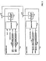
- Fig. 2 is a block diagram of receive and transmit systems configured as a subscriber unit 100 and a base station 120 in accordance with one embodiment of the invention.
- a first set of data (BPSK data) is received by BPSK channel encoder 103, which generates a code symbol stream configured for performing BPSK modulation that is received by modulator 104.
- a second set of data (QPSK data) is received by QPSK channel encoder 102, which generates a code symbol stream configured for performing QPSK modulation that is also received by modulator 104.
- Modulator 104 also receives power control data and pilot data, which are modulated along with the BPSK and QPSK encoded data in accordance with code division multiple access (CDMA) techniques to generate a set of modulation symbols received by RF processing system 106.
- RF processing system 106 filters and upconverts the set of modulation symbols to a carrier frequency for transmission to the base station 120 using antenna 108. While only one subscriber unit 100 is shown, multiple subscriber units may communicate with base station 120.
- RF processing system 122 receives the transmitted RF signals by way of antenna 121 and performs bandpass filtering, downconversion to baseband, and digitization.
- Demodulator 124 receives the digitized signals and performs demodulation in accordance with CDMA techniques to produce power control, BPSK, and QPSK soft decision data.
- BPSK channel decoder 128 decodes the BPSK soft decision data received from demodulator 124 to yield a best estimate of the BPSK data
- QPSK channel decoder 126 decodes the QPSK soft decision data received by demodulator 124 to produce a best estimate of the QPSK data.
- the best estimate of first and second set of data is then available for further processing or forwarding to a next destination, and the received power control data used either directly, or after decoding, to adjust the transmit power of the forward link channel used to transmit data to subscriber unit 100.
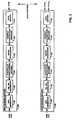
- Fig. 3 is a block diagram of BPSK channel encoder 103 and QPSK channel encoder 102 when configured in accordance with the exemplary embodiment of the invention.
- the BPSK data is received by CRC check sum generator 130 which generates a check sum for each 20 ms frame of the first set of data.
- the frame of data along with the CRC check sum is received by tail bit generator 132 which appends tail bits comprised of eight logic zeros at the end of each frame to provide a known state at the end of the decoding process.
- convolutional encoder 134 which performs, constraint length (K) 9, rate (R) 1/4 convolutional encoding thereby generating code symbols at a rate four times the encoder input rate (E R ).
- K constraint length
- R rate 1/4 convolutional encoding
- other encoding rates are performed including rate 1/2, but the use of rate 1/4 is preferred due to its optimal complexity-performance characteristics.
- Block interleaver 136 performs bit interleaving on the code symbols to provide time diversity for more reliable transmission in fast fading environments.
- variable starting point repeater 138 which repeats the interleaved symbol sequence a sufficient number of times N R to provide a constant rate symbol stream, which corresponds to outputting frames having a constant number of symbols. Repeating the symbol sequence also increases the time diversity of the data to overcome fading.
- the constant number of symbols is equal to 6,144 symbols for each frame making the symbol rate 307.2 kilosymbols per second (ksps).
- repeater 138 uses a different starting point to begin the repetition for each symbol sequence. When the value of N R necessary to generate 6,144 symbols per frame is not an integer, the final repetition is only performed for a portion of the symbol sequence.
- BPSK mapper 139 which generates a BPSK code symbol stream (BPSK) of +1 and -1 values for performing BPSK modulation.
- repeater 138 is placed before block interleaver 136 so that block interleaver 136 receives the same number of symbols for each frame.
- the QPSK data is received by CRC check sum generator 140 which generates a check sum for each 20 ms frame.
- the frame including the CRC check sum is received by code tail bits generator 142 which appends a set of eight tail bits of logic zeros at the end of the frame.
- Block interleaver 146 performs bit interleaving on the symbols and the resulting interleaved symbols are received by variable starting point repeater 148.
- Variable starting point repeater 148 repeats the interleaved symbol sequence a sufficient number of times N R using a different starting point within the symbol sequence for each repetition to generate 12,288 symbols for each frame making the code symbol rate 614.4 kilosymbols per second (ksps).
- N R is not an integer
- the final repetition is performed for only a portion of the symbol sequence.
- the resulting repeated symbols are received by QPSK mapper 149 which generates a QPSK code symbol stream configured for performing QPSK modulation comprised of an in-phase QPSK code symbol stream of +1 and -1 values (QPSK I ), and a quadrature-phase QPSK code symbol stream of +1 and -1 values (QPSK Q ).
- repeater 148 is placed before block interleaver 146 so that block interleaver 146 receives the same number of symbols for each frame.
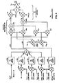
- Fig. 4 is a block diagram of modulator 104 of Fig. 2 configured in accordance with the exemplary embodiment of the invention.
- the BPSK symbols from BPSK channel encoder 103 are each modulated by Walsh code W 2 using a multiplier 150b, and the QPSK I and QPSK Q symbols from QPSK channel encoder 102 are each modulated with Walsh code W 3 using multipliers 150c and 154d.
- the power control data (PC) is modulated by Walsh code W 1 using multiplier 150a.
- Gain adjust 152 receives pilot data (PILOT), which in the preferred embodiment of the invention is comprised of the logic level associated with positive voltage, and adjusts the amplitude according to a gain adjust factor A 0 .
- PILOT pilot data
- the PILOT signal provides no user data but rather provides phase and amplitude information to the base station so that it can coherently demodulate the data carried on the remaining sub-channels, and scale the soft-decision output values for combining.
- Gain adjust 154 adjusts the amplitude of the Walsh code W 1 modulated power control data according to gain adjust factor A 1
- gain adjust 156 adjusts the amplitude of the Walsh code W 2 modulated BPSK channel data according amplification variable A 2
- Gain adjusts 158a and b adjust the amplitude of the in-phase and quadrature-phase Walsh code W 3 modulated QPSK symbols respectively according to gain adjust factor A 3 .
- Table I Walsh Code Modulation Symbols W 0 + + + + + + + + W 1 + - + - W 2 + + - - W 3 + - - +
- the W 0 code is effectively no modulation at all, which is consistent with processing of the pilot data shown.
- the power control data is modulated with the W 1 code, the BPSK data with the W 2 code, and the QPSK data with the W 3 code.
- the pilot, power control data, and BPSK data are transmitted in accordance with BPSK techniques, and the QPSK data (QPSK I and QPSK Q ) in accordance with QPSK techniques as described below. It should also be understood that it is not necessary that every orthogonal channel be used, and that the use of only three of the four Walsh codes where only one user channel is provided is employed in an alternative embodiment of the invention.
- short orthogonal codes generates fewer chips per symbol, and therefore allows for more extensive coding and repetition when compared to systems incorporating the use of longer Walsh codes. This more extensive coding and repetition provides protection against Raleigh fading which is a major source of error in terrestrial communication systems.
- the use of other numbers of codes and code lengths is consistent with the present invention, however, the use of a larger set of longer Walsh codes reduces this enhanced protection against fading.
- the use of four chip codes is considered optimal because four channels provides substantial flexibility for the transmission of various types of data as illustrated below while also maintaining short code length.
- Summer 160 sums the resulting amplitude adjusted modulation symbols from gain adjusts 152, 154, 156 and 158a to generate summed modulation symbols 161.
- PN spreading codes PN I and PN Q are spread via multiplication with long code 180 using multipliers 162a and b.
- the resulting pseudorandom code provided by multipliers 162a and 162b are used to modulate the summed modulation symbols 161, and gain adjusted quadrature-phase symbols QPSK Q 163, via complex multiplication using multipliers 164a-d and summers 166a and b.
- the resulting in-phase term X I and quadrature-phase term X Q are then filtered (filtering not shown), and upconverted to the carrier frequency within RF processing system 106 shown in a highly simplified form using multipliers 168 and an in-phase and a quadrature-phase sinusoid.
- An offset QPSK upconversion could also be used in an alternative embodiment of the invention.
- the resulting in-phase and quadrature-phase upconverted signals are summed using summer 170 and amplified by master amplifier 172 according to master gain adjust A M to generate signal s(t) which is transmitted to base station 120.
- the signal is spread and filtered to a 1.2288 MHz bandwidth to remain compatible with the bandwidth of existing CDMA channels.
- the above described method and system of transmit signal processing allows a single subscriber unit or other transmit system to transmit data at a variety of data rates.
- rate 1/2 convolution encoding is performed with the rate of repetition N R increased by two.
- a set of exemplary encoder rates E R supported by various rates of repetition N R and encoding rates R equal to 1/4 and 1/2 for the BPSK channel and the QPSK channel are shown in Tables II and III respectively.
- Tables II and III show that by adjusting the number of sequence repetitions N R , a wide variety of data rates can be supported including high data rates, as the encoder input rate E R corresponds to the data transmission rate minus a constant necessary for the transmission of CRC, code tail bits and any other overhead information. As also shown by tables II and III, QPSK modulation may also be used to increase the data transmission rate.
- Rates expected to be used commonly are provided labels such as "High Rate-72" and "High Rate-32.” Those rates noted as High Rate-72, High Rate-64, and High Rate-32 have traffic rates of 72, 64 and 32 kbps respectively, plus multiplexed in signaling and other control data with rates of 3.6, 5.2, and 5.2 kbps respectively, in the exemplary embodiment of the invention. Rates RS1-Full Rate and RS2-Full Rate correspond to rates used in IS-95 compliant communication systems, and therefore are also expected to receive substantial use for purposes of compatibility.
- the null rate is the transmission of a single bit and is used to indicate a frame erasure, which is also part of the IS-95 standard.
- the data transmission rate may also be increased by simultaneously transmitting data over two or more of the multiple orthogonal channels performed either in addition to, or instead of, increasing the transmission rate via reduction of the repetition rate N R .
- a multiplexer (not shown) could split a single data source into a multiple data sources to be transmitted over multiple data sub-channels.
- the total transmit rate can be increased via either transmission over a particular channel at higher rates, or multiple transmission performed simultaneously over multiple channels, or both, until the signal processing capability of the receive system is exceeded and the error rate becomes unacceptable, or the maximum transmit power of the of the transmit system power is reached.
- the BPSK channel may be designated for voice information and the QPSK channel designated for transmission of digital data.
- This embodiment could be more generalized by designating one channel for transmission of time sensitive data such as voice at a lower data rate, and designating the other channel for transmission of less time sensitive data such as digital files. In this embodiment interleaving could be performed in larger blocks for the less time sensitive data to further increase time diversity.
- the BPSK channel performs the primary transmission of data
- the QPSK channel performs overflow transmission.
- orthogonal Walsh codes eliminates or substantially reduces any interference among the set of channels transmitted from a subscriber unit, and thus minimizes the transmit energy necessary for their successful reception at the base station.
- pilot data is also transmitted via one of the orthogonal channels.
- coherent processing can be performed at the receive system by determining and removing the phase offset of the reverse link signal.
- the pilot data can be used to optimally weigh multipath signals received with different time delays before being combined in a rake receiver. Once the phase offset is removed, and the multipath signals properly weighted, the multipath signals can be combined decreasing the power at which the reverse link signal must be received for proper processing. This decrease in the required receive power allows greater transmissions rates to be processed successfully, or conversely, the interference between a set of reverse link signals to be decreased.
- gain adjusts 152 - 158 as well as master amplifier 172 further increases the degree to which the high transmission capability of the above described system can be utilized by allowing the transmit system to adapt to various radio channel conditions, transmission rates, and data types.
- the transmit power of a channel that is necessary for proper reception may change over time, and with changing conditions, in a manner that is independent of the other orthogonal channels.
- the power of the pilot channel may need to be increased to facilitate detection and synchronization at the base station. Once the reverse link signal is acquired, however, the necessary transmit power of the pilot channel would substantially decrease, and would vary depending on various factors including the subscriber units rate of movement.
- the value of the gain adjust factor A 0 would be increased during signal acquisition, and then reduced during an ongoing communication.
- the gain adjust factor A 1 may be reduced as the need to transmit power control data with a low error rate decreases. In one embodiment of the invention, whenever power control adjustment is not necessary the gain adjust factor A 1 is reduced to zero.
- the ability to gain adjust each orthogonal channel or the entire reverse link signal is further exploited by allowing the base station 120 or other receive system to alter the gain adjust of a channel, or of the entire reverse link signal, via the use of power control commands transmitted via the forward link signal.
- the base station may transmit power control information requesting the transmit power of a particular channel or the entire reverse link signal be adjusted. This is advantageous in many instances including when two types of data having different sensitivity to error, such as digitized voice and digital data, are being transmitted via the BPSK and QPSK channels. In this case, the base station 120 would establish different target error rates for the two associated channels.
- the base station would instruct the subscriber unit to reduce the gain adjust of that channel until the actual error rate reached the target error rate. This would eventually lead to the gain adjust factor of one channel being increased relative to the other. That is, the gain adjust factor associated with the more error sensitive data would be increased relative to the gain adjust factor associated with the less sensitive data.
- the transmit power of the entire reverse link may require adjustment due to fade conditions or movement of the subscriber unit 100. In these instances, the base station 120 can do so via transmission of a single power control command.
- the total transmit power of the reverse link signal can be kept at the minimum necessary for successful transmission of each data type, whether it is pilot data, power control data, signaling data, or different types of user data.
- successful transmission can be defined differently for each data type. Transmitting with the minimum amount of power necessary allows the greatest amount of data to be transmitted to the base station given the finite transmit power capability of a subscriber unit, and also reduces the interfere between subscriber units. This reduction in interference increases the total communication capacity of the entire CDMA wireless cellular system.
- the power control channel used in the reverse link signal allows the subscriber unit to transmit power control information to the base station at a variety of rates including a rate of 800 power control bits per second.
- a power control bit instructs the base station to increase or decrease the transmit power of the forward link traffic channel being used to transmit information to the subscriber unit. While it is generally useful to have rapid power control within a CDMA system, it is especially useful in the context of higher data rate communications involving data transmission, because digital data is more sensitive to errors, and the high transmission causes substantial amounts of data to be lost during even brief fade conditions. Given that a high speed reverse link transmission is likely to be accompanied by a high speed forward link transmission, providing for the rapid transmission of power control over the reverse link further facilitates high speed communications within CDMA wireless telecommunications systems.
- a set of encoder input rates E R defined by the particular N R are used to transmit a particular type of data. That is, data may be transmitted at a maximum encoder input rate E R or at a set of lower encoder input rates E R , with the associated N R adjusted accordingly.
- the maximum rates corresponds to the maximum rates used in IS-95 compliant wireless communication system, referred to above with respect to Tables II and III as RS1-Full Rate and RS2-Full Rate, and each lower rate is approximately one half the next higher rate, creating a set of rates comprised of a full rate, a half rate, a quarter rate, and an eighth rate.
- the lower data rates are preferable generated by increasing the symbol repetition rate N R with value of N R for rate set one and rate set two in a BPSK channel provided in Table IV.
- the repetition rates for a QPSK channel is twice that for the BPSK channel.
- the transmit power of the frame is adjusted according to the change in transmission rate. That is, when a lower rate frame is transmitted after a higher rate frame, the transmit power of the transmit channel over which the frame is being transmitted is reduced for the lower rate frame in proportion to the reduction in rate, and vice versa. For example, if the transmit power of a channel during the transmission of a full rate frame is transmit power T, the transmit power during the subsequent transmission of a half rate frame is transmit power T/2.
- the reduction is transmit power is preferably performed by reducing the transmit power for the entire duration of the frame, but may also be performed by reducing the transmit duty cycle such that some redundant information is "blanked out.” In either case, the transmit power adjustment takes place in combination with a closed loop power control mechanism whereby the transmit power is further adjusted in response to power control data transmitted from the base station.
- Fig. 5 is a block diagram of RF processing system 122 and demodulator 124 of Fig. 2 configured in accordance with the exemplary embodiment of the invention.
- Multipliers 180a and 180b dowconvert the signals received from antenna 121 with an in-phase sinusoid and a quadrature phase sinusoid producing in-phase receive samples R I and quadrature-phase receive samples R Q receptively.
- RF processing system 122 is shown in a highly simplified form, and that the signals are also match filtered and digitized (not shown) in accordance with widely known techniques.
- Receive samples R I and R Q are then applied to finger demodulators 182 within demodulator 124.
- Each finger demodulator 182 processes an instance of the reverse link signal transmitted by subscriber unit 100, if such an instance is available, where each instance of the reverse link signal is generated via multipath phenomenon. While three finger demodulators are shown, the use of alternative numbers of finger processors are consistent with the invention including the use of a single finger demodulator 182.
- Each finger demodulator 182 produces a set of soft decision data comprised of power control data, BPSK data, and QPSK I data and QPSK Q data.
- Each set of soft decision data is also time adjusted within the corresponding finger demodulator 182, although time adjustment could be performed within combiner 184 in an alternative embodiment of the invention.
- Combiner 184 then sums the sets of soft decision data received from finger demodulators 182 to yield a single instance of power control, BPSK, QPSK I and QPSK Q soft decision data.
- Fig. 6 is block diagram a finger demodulator 182 of Fig. 5 configured in accordance with the exemplary embodiment of the invention.
- the R I and R Q receive samples are first time adjusted using time adjust 190 in accordance with the amount of delay introduced by the transmission path of the particular instance of the reverse link signal being processed.
- Long code 200 is mixed with pseudorandom spreading codes PN I and PN Q using multipliers 201, and the complex conjugate of the resulting long code modulated PN I and PN Q spreading codes are complex multiplied with the time adjusted R I and R Q receive samples using multipliers 202 and summers 204 yielding terms X I and X Q .
- pilot filter 214 performs averaging over a series of summations performed by summers 208, but other filtering techniques will be apparent to one skilled in the art.
- the filtered in-phase and quadrature-phase pilot signals are used to phase rotate and scale the W 1 , and W 2 Walsh code demodulated data in accordance with BPSK modulated data via complex conjugate multiplication using multipliers 216 and adders 217 yielding soft decision power control and BPSK data.
- the W 3 Walsh code modulated data is phase rotated using the in-phase and quadrature-phase filtered pilot signals in accordance with QPSK modulated data using multipliers 218 and adders 220, yielding soft decision QPSK data.
- the soft decision power control data is summed over 384 modulation symbols by 384 to 1 summer 222 yielding power control soft decision data.
- the phase rotated W 2 Walsh code modulated data, the W 3 Walsh code modulated data, and the power control soft decision data are then made available for combining.
- encoding and decoding is performed on the power control data as well.
- the pilot may also be used within the receive system to facilitate time tracking.
- Time tracking is performed by also processing the received data at one sample time before (early), and one sample time after (late), the present receive sample being processed.
- the amplitude of the pilot channel at the early and late sample time can be compared with the amplitude at the present sample time to determine that which is greatest. If the signal at one of the adjacent sample times is greater than that at the present sample time, the timing can be adjusted so that the best demodulation results are obtained.
- FIG. 7 is a block diagram of BPSK channel decoder 128 and QPSK channel decoder 126 (Fig. 2) configured in accordance with the exemplary embodiment of the invention.
- BPSK soft decision data from combiner 184 (Fig. 5) is received by accumulator 240 which stores the first sequence of 6,144/N R demodulation symbols in the received frame where N R depends on the transmission rate of the BPSK soft decision data as described above, and adds each subsequent set of 6,144/N R demodulated symbols contained in the frame with the corresponding stored accumulated symbols.
- Block deinterleaver 242 deinterleaves the accumulated soft decision data from variable starting point summer 240, and Viterbi decoder 244 decodes the deinterleaved soft decision data to produce hard decision data as well as CRC check sum results.
- QPSK decoder 126 QPSK I and QPSK Q soft decision data from combiner 184 (Fig. 5) are demultiplexed into a single soft decision data stream by demux 246 and the single soft decision data stream is received by accumulator 248 which accumulates every 6,144/N R demodulation symbols where N R depends on the transmission rate of the QPSK data.
- Block deinterleaver 250 deinterleaves the soft decision data from variable starting point summer 248, and Viterbi decoder 252 decodes the deinterleaved modulation symbols to produce hard decision data as well as CRC check sum results.
- accumulators 240 and 248 are placed after block deinterleavers 242 and 250.
- multiple decoders are employed, each operating at a different transmission rate, and then the frame associated with the transmission rate most likely to have been used is selected based on the CRC checksum results. The use of other error checking methods is consistent with the practice of the present invention.
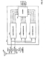
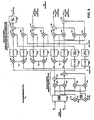
- FIG. 8 a reverse link transmission system in which the control data and the pilot data have been combined onto one channel is illustrated.
- the control data can be multiplexed onto other channels transmitted by the remote station.
- the control data is multiplexed onto the pilot channel because unlike the fundamental and supplemental channels, the pilot channel is always present regardless of whether the remote station has traffic data to send to the central communications station.
- the present invention is described in terms of multiplexing the data onto the pilot channel, it is equally applicable to the case where the power control data is punctured into the pilot channel.
- Pilot data which consists solely of a stream of binary "1" values are provided to multiplexer (MUX) 300.
- control channel data which in the exemplary embodiment is power control data consisting of +1 and -1 values indicative of instruction for the base station to increase or decrease its transmission power, are provided to MUX 300.
- Multiplexer 300 combines the two data streams by providing the control data into predetermined positions in the pilot data. The multiplexed data is then provided to a first input of multipliers 310 and 328.
- the second input of multiplier 310 is provided with a pseudonoise (PN) sequence of +1 and -1 values.
- the pseudonoise sequence provided to multipliers 310 and 312 is generated by multiplying the short PN sequence (PN I ) by the long code.
- the generation of short PN sequences and long code sequences is well known in the art and described in detail in the IS-95 standard.
- the second input of multiplier 328 is provided with a pseudonoise (PN) sequence of +1 and -1 values.
- the pseudo noise sequence provided to multipliers 318 and 328 is generated by multiplying the short PN sequence (PN Q ) by the long code.
- the output of multiplier 310 is provided to a first input of multiplier 314.
- the output of multiplier 318 is provided to delay element 320 which delays the input data by a time interval equal to half a chip.
- Delay element 320 provides the delayed signal to the subtracting input of subtractor 314.
- the output of subtractor 314 is provided for transmission to baseband filters and pilot gain elements (not shown).
- the output of multiplier 328 is provided to delay element 330 which delays the input data by half a chip cycle as described with respect to delay 320.
- the output of delay element 330 is provided to a second summing input of summer 322.
- the first input of summing element 322 is the output of multiplier 312.
- the summed output from summer 322 is provided for transmission to baseband filters and pilot gain elements (not shown).
- Traffic data to be transmitted on the supplemental channel consisting of +1 and -1 values, is provided to a first input of multiplier 302.
- the second input of multiplier 302 is provided with a repeating Walsh sequence (+1, -1). As described above the Walsh covering is to reduce the interference between channels of data transmitted from the remote station.
- the product data sequence from multiplier 302 is provided to gain element 304 which scales the amplitude to a value determined relative to the pilot/control channel amplification.
- the output of gain element 304 is provided to a first input of summer 316.
- the output of summer 316 is provided to the inputs of multipliers 312 and 318 and processing continues as described above.
- Traffic data to be transmitted on the fundamental channel consisting of +1 and -1 values, is provided to a first input of multiplier 306.
- the second input of multiplier 306 is provided with a repeating Walsh sequence (+1,+1,-1,-1). As described above the Walsh covering reduces the interference between channels of data transmitted from the remote station.
- the product data sequence from multiplier 306 is provided to gain element 308 which scales the amplitude to a value determined relative to the pilot/control channel amplification.
- the output of gain element 308 is provided to a second input of summer 316.
- the output of summer 316 is provided to the inputs of multipliers 312 and 318 and processing continues as described above.
- the embodiment of the present invention is illustrated to include the necessary filtering operations and illustrates an additional benefit attained by combining the pilot and control data. That is a reduction in the amount of necessary filtering circuitry.
- the pilot data and control channel data are multiplexed together by multiplexer (MUX) 350.
- the multiplexed data consisting of +1 and -1 values, is provided to a first input of multipliers 352 and 354.
- the second input of multiplier 352 is provided by multiplying the short PN code PN I by the long code in multiplier 390.
- the product from multiplier 352 is provided to finite impulse response (FIR) filter 356.
- FIR finite impulse response
- FIR 356 is a 48 tap FIR filter, the design of which is well known in the art.
- the second input of multiplier 354 is provided by multiplying the short PN code PN Q by the long code in multiplier 392.
- the output of FIR 356 is provided to the summing input of subtractor 374.
- the output of subtractor 374 is provided for transmission to upconverters and pilot gain elements (not shown).
- FIR filter 358 The product from multiplier 354 is provided to finite impulse response (FIR) filter 358.
- FIR 358 is a 48 tap FIR filter, the design of which is well known in the art. It should be noted that by combining the pilot and power control data, two FIR filters have been eliminated since each channel requires two FIR filters. Elimination of two FIR filters reduces complexity, power consumption and chip area.
- the output of FIR 358 is provided to delay element 360 which delays the output by half a chip before providing the signal to a first summing input of summer 376.
- the output of summer 376 is provided for transmission to upconverters and pilot gain elements (not shown).
- the supplemental channel traffic data consisting of +1 and -1 values are provided to a first input of multiplier 362.
- the second input to multiplier 362 is a repeating Walsh sequence (+1,-1) which as described previously reduce interference between the channels.
- the output of multiplier 362 is provided to a first input of multipliers 364 and 366.
- the second input of multiplier 364 is the pseudonoise sequence provided from multiplier 392 and the second input to multiplier 366 is the pseudonoise sequence provided from multiplier 390.
- the output from multiplier 364 is provided to FIR/gain element 368 which filters the signal and amplifies the signal in accordance with a gain factor relative to unity gain of the pilot/control channel.
- the output of FIR/gain element 368 is provided to delay element 372.
- Delay element 372 delays the signal by 1/2 a chip before providing the signal to a first subtracting input of subtracting element 374. Processing of the output of subtractor 374 proceeds as described above.
- the output from multiplier 366 is provided to FIR/gain element 370 which filters the signal and amplifies the signal in accordance with a gain factor relative to unity gain of the pilot/control channel.
- the output of FIR/gain element 370 is provided to a second input of summing element 376. Processing of the output of subtractor 376 proceeds as described above.
- the fundamental channel traffic data consisting of +1 and -1 values is provided to a first input of multiplier 388 .
- the second input to multiplier 388 is a repeating Walsh sequence (+1,+1,-1,-1) which as described previously reduces interference between the channels.
- the output of multiplier 388 is provided to a first input of multipliers 378 and 384.
- the second input of multiplier 378 is the pseudonoise sequence provided from multiplier 392 and the second input to multiplier 384 is the pseudonoise sequence provided from multiplier 390.
- the output from multiplier 378 is provided to FIR/gain element 380 which filters the signal and amplifies the signal in accordance with a gain factor relative to unity gain of the pilot/control channel.
- the output of FIR/gain element 380 is provided to delay element 382.
- Delay element 382 delays the signal by 1/2 a chip before providing the signal to a second subtracting input of subtracting element 374. Processing of the output of subtractor 374 proceeds as described above.
- the output from multiplier 384 is provided to FIR/gain element 386 which filters the signal and amplifies the signal in accordance with a gain factor relative to unity gain of the pilot/control channel.
- the output of FIR/gain element 386 is provided to a third input of summing element 376. Processing of the output of subtractor 376 proceeds as described above.
- a receiver for processing the data wherein the control data is multiplexed with the pilot signal data is illustrated.
- the data is received by an antenna(not shown) and downconverted, filtered and sampled.
- the filtered data samples are provided to delay elements 400 and 402.
- Delay element 400 and 402 delay the data by half of a chip cycle before providing the data to a first input of multipliers 404 and 406.
- the second input of multipliers 404 and 406 are provided with a pseudonoise sequence provided by multiplier 450.
- Multiplier 450 generates the pseudonoise sequence by multiplying the short code PN I by the long code as described previously.
- the filtered samples are also provided directly (without delay) to a first input of multipliers 446 and 448.
- the second input of multipliers 446 and 448 are provided with a pseudonoise sequence by multiplier 452.
- Multiplier 452 generates the pseudonoise sequence by multiplying the short PN code (PN Q ) by the long code.
- the output from multiplier 404 is provided to a first input of summer 408, and the output from multiplier 446 is provided to a second input of summer 408.
- the output from multiplier 406 is provided to a summing input of subtractor 410, and the output from multiplier 448 is provided to a subtracting input of subtractor 410.
- pilot symbol selector 434 gates out the control data from the pilot data, before providing the signal to pilot filter 436. Pilot filter 436 filters the signal and provides the filtered pilot signal to multipliers 416 and 418. Similarly, pilot symbol selector 438 gates out the control data from the pilot data, before providing the signal to pilot filter 440. Pilot filter 440 filters the signal and provides the filtered pilot signal to multipliers 442 and 444.
- Delay 412 is used to synchronize the data through the two paths, before they are provided to multiplier 416. That is to say that delay element 412 provides a delay that is equal to the processing delay of pilot symbol selector 434 and pilot filter 436 which is equal to the processing delay of pilot symbol selector 438 and pilot filter 440. Similarly delay element 414 synchronizes the data provided to multipliers 418 and 442.
- the output of delay element 412 is provided to a first input of multipliers 416 and 444.
- the second input to multiplier 416 is provided by the output of pilot filter 436.
- the second input to multiplier 444 is provided by pilot filter 440.
- the output of delay element 414 is provided to a first input to multipliers 418 and 442.
- the second input to multiplier 418 is provided by the output of pilot filter 436.
- the second input to multiplier 442 is provided by pilot filter 440.
- the output of multiplier 416 is provided to a first input of summer 420 and the second input to summer 420 is provided by the output of multiplier 442.
- the sum from summer 420 is provided to control symbol selector 424 which separates the control data from the pilot channel data and provides that information to a control processor not show which adjusts the base station transmission power in response thereto.
- the output from multiplier 418 is provided to a summing input of subtractor 422.
- the output from multiplier 444 is provided to a subtracting input of subtractor 422.
- the output of subtractor 422 is provided to a first input of multiplier 426.
- the second input of multiplier 426 is provided with the repeating Walsh sequence (+1,-1).
- the product from multiplier 426 is provided to summing element 428 which sums the input bits over the Walsh sequence period to provide the supplemental channel data.
- the output of subtractor 422 is provided to a first input of multiplier 430.
- the second input of multiplier 430 is provided with the repeating Walsh sequence (+1,+1,-1,-1).
- the product from multiplier 430 is provided to summing element 432 which sums the input bits over the Walsh sequence period to provide the fundamental channel data.
Abstract
Description
- The present invention relates to a subscriber unit and method for use in a wireless communication system.
- Wireless communication systems including cellular, satellite and point to point communication systems use a wireless link comprised of a modulated radio frequency (RF) signal to transmit data between two systems. The use of a wireless link is desirable for a variety of reasons including increased mobility and reduced infrastructure requirements when compared to wire line communication systems. One drawback of using a wireless link is the limited amount of communication capacity that results from the limited amount of available RF bandwidth. This limited communication capacity is in contrast to wire based communication systems where additional capacity can be added by installing additional wire line connections.
- Recognizing the limited nature of RF bandwidth, various signal processing techniques have been developed for increasing the efficiency with which wireless communication systems utilize the available RF bandwidth. One widely accepted example of such a bandwidth efficient signal processing technique is the IS-95 over the air interface standard and its derivatives such as IS-95-A and ANSI J-STD-008 (referred to hereafter collectively as the IS-95 standard) promulgated by the telecommunication industry association (TIA) and used primarily within cellular telecommunications systems. The IS-95 standard incorporates code division multiple access (CDMA) signal modulation techniques to conduct multiple communications simultaneously over the same RF bandwidth. When combined with comprehensive power control, conducting multiple communications over the same bandwidth increases the total number of calls and other communications that can be conducted in a wireless communication system by, among other things, increasing the frequency reuse in comparison to other wireless telecommunication technologies. The use of CDMA techniques in a multiple access communication system is disclosed in
U.S. Patent No. 4,901,307 , entitled "SPREAD SPECTRUM COMMUNICATION SYSTEM USING SATELLITE OR TERRESTRIAL REPEATERS", andU.S. Patent No. 5,103,459 , entitled "SYSTEM AND METHOD FOR GENERATING SIGNAL WAVEFORMS IN A CDMA CELLULAR TELEPHONE SYSTEM", both of which are assigned to the assignee of the present invention and incorporated by reference herein. - Fig. 1 provides a highly simplified illustration of a cellular telephone system configured in accordance with the use of the IS-95 standard. During operation, a set of
subscriber units 10a - d conduct wireless communication by establishing one or more RF interfaces with one ormore base stations 12a - d using CDMA modulated RF signals. Each RF interface between a base station 12 and asubscriber unit 10 is comprised of a forward link signal transmitted from the base station 12, and a reverse link signal transmitted from the subscriber unit. Using these RF interfaces, a communication with another user is generally conducted by way of mobile telephone switching office (MTSO) 14 and public switch telephone network (PSTN) 16. The links between base stations 12, MTSO 14 and PSTN 16 are usually formed via wire line connections, although the use of additional RF or microwave links is also known. - In accordance with the IS-95 standard each
subscriber unit 10 transmits user data via a single channel, non-coherent, reverse link signal at a maximum data rate of 9.6 or 14.4 kbits/sec depending on which rate set from a set of rate sets is selected. A non-coherent link is one in which phase information is not utilized by the received system. A coherent link is one in which the receiver exploits knowledge of the carrier signals phase during processing. The phase information typically takes the form of a pilot signal, but can also be estimated from the data transmitted. The IS-95 standard calls for a set of sixty four Walsh codes, each comprised of sixty four chips, to be used for the forward link. - The use of a single channel, non-coherent, reverse link signal having a maximum data rate of 9.6 of 14.4 kbits/sec as specified by IS-95 is well suited for a wireless cellular telephone system in which the typical communication involves the transmission of digitized voice or lower rate digital data such a facsimile. A non-coherent reverse link was selected because, in a system in which up to 80
subscriber units 10 may communicate with a base station 12 for each 1.2288 MHz of bandwidth allocated, providing the necessary pilot data in the transmission from eachsubscriber unit 10 would substantially increase the degree to which a set ofsubscriber units 10 interfere with one another. Also, at data rates of 9.6 or 14.4 kbits/sec, the ratio of the transmit power of any pilot data to the user data would be significant, and therefore also increase inter-subscriber unit interference. The use of a single channel reverse link signal was chosen because engaging in only one type of communication at a time is consistent with the use of wireline telephones, the paradigm on which current wireless cellular communications is based. Also, the complexity of processing a single channel is less than that associated with processing multiple channels. - As digital communications progress, the demand for wireless transmission of data for applications such as interactive file browsing and video teleconferencing is anticipated to increase substantially. This increase will transform the way in which wireless communications systems are used, and the conditions under which the associated RF interfaces are conducted. In particular, data will be transmitted at higher maximum rates and with a greater variety of possible rates. Also, more reliable transmission may become necessary as errors in the transmission of data are less tolerable than errors in the transmission of audio information. Additionally, the increased number of data types will create a need to transmit multiple types of data simultaneously. For example, it may be necessary to exchange a data file while maintaining an audio or video interface. Also, as the rate of transmission from a subscriber unit increases the number of
subscriber units 10 communicating with a base station 12 per amount of RF bandwidth will decrease, as the higher data transmission rates will cause the data processing capacity of the base station to be reached withfewer subscriber units 10. In some instances, the current IS-95 reverse link may not be ideally suited for all these changes. Therefore, the present invention is related to providing a higher data rate, bandwidth efficient, CDMA interface over which multiple types of communication can be performed. - In one aspect the invention provides a subscriber unit or other transmitter for use in a wireless communication system, the subscriber unit comprising: plural information sources of information data; an encoder for encoding the information data; plural control sources of control data; and a modulator for modulating encoded information data with respective different modulating codes for transmission on a carrier signal, for combining the control data from the plural sources, and outputting the encoded information data and the combined control data for transmission.
- In another aspect the invention provides a base station or other receiver for use in a wireless communication system, the base station comprising: a receiver for receiving a carrier signal and removing therefrom encoded information data from plural information sources modulated with respective different modulating codes and control data from plural control sources with the encoded control data being combined with each other; a demodulator for demodulating the encoded information data and the control data from their respective different modulating codes; and a decoder for decoding the encoded information data and demodulating the control data.
- In a further aspect the invention provides a method of transmission in a wireless communication system, the method comprising: acquiring plural information data; encoding the information data; acquiring plural control data; modulating encoded information data with respective different modulating codes for transmission on a carrier signal; combining the control data from the plural sources; and outputting the encoded information data and the combined control data for transmission.
- In another aspect the invention provides a method for generating modulated data for transmission from a first subscriber unit in a set of subscriber units wherein said first subscriber unit transmits control data and pilot data to a base station in communication with the set of subscriber units comprising: a) combining said control data with said pilot data; and b)
modulating said combined control data and pilot data onto in accordance with a single channel modulation format. - In accordance with one embodiment of the invention, a set of individually gain adjusted subscriber channels are formed via the use of a set of orthogonal subchannel codes having a small number of PN spreading chips per orthogonal waveform period. Data to be transmitted via one of the transmit channels is low code rate error correction encoded and sequence repeated before being modulated with one of the subchannel codes, gain adjusted, and summed with data modulated using the other subchannel codes. The resulting summed data is modulated using a user long code and a pseudorandom spreading code (PN code) and upconverted for transmission. The use of the short orthogonal codes provides interference suppression while still allowing extensive error correction coding and repetition for time diversity to overcome the Raleigh fading commonly experienced in terrestrial wireless systems. In the exemplary embodiment of the invention provided, the set of sub-channel codes are comprised of four Walsh codes, each orthogonal to the remaining set and four chips in duration.
- In a preferred embodiment of the invention, two of the subscriber channel channels are multiplexed into a single traffic channel. The use of fewer traffic channels is preferred as it allows a smaller peak-to-average transmit power ratio. The use of different numbers of traffic channels is consistent with the invention.
- In a first exemplary embodiment of the invention, pilot data is transmitted via a first one of the transmit channels and power control and other frame-by-frame control data are transmitted via a second transmit channel. In a preferred embodiment, the information on the pilot channel and the control subscriber channel, which includes the power control and frame-by-frame control data, are multiplex together onto one traffic channel to reduce the peak-to-average power ratio while still allowing for a continuous transmission. A continuous transmission is very desirably because it minimizes the possible interference with personal electronic equipment such as hearing aids and pacemakers. Since the pilot and control data are always transmitted, the resulting signal is still continuous. The other traffic channels are typically only active when the data of the type of that traffic channel is active. If the control data were multiplexed with a subscriber channel other than the pilot subscriber channel, the resulting traffic channel waveform would be discontinuous when the original traffic channel data is inactive. The other subscriber traffic channels could also be multiplexed into a single transmit channel. Two separate subscriber traffic channels are used here to allow for different gains and frame retransmission approaches for different types of traffic. The remaining two transmit channels are used for transmitting non-specified digital data including user data or signaling data, or both. In the exemplary embodiment, one of the two non-specified transmit channels is configured for BPSK modulation and the other for QPSK modulation. This is done to illustrate the versatility of the system. Both channels could be BPSK modulated or QPSK modulated in alternative embodiments of the invention.
- Before modulation, the non-specified data is encoded where that encoding includes cyclic redundancy check (CRC) generation, convolutional encoding, interleaving, selective sequence repeating and BPSK or QPSK mapping. By varying the amount of repeating performed, and not restricting the amount of repeating to an integer number of symbol sequences, a wide variety of transmission rates including high data rates can be achieved. Furthermore, higher data rates can also be achieved by transmitting data simultaneously over both non-specified transmit channels. Also, by frequently updating the gain adjust performed on each transmit channel, the total transmit power used by the transmit system may be kept to a minimum such that the interference generated between multiple transmit systems is minimized, thereby increasing the overall system capacity.
- The features, objects, and advantages of the present invention will become more apparent from the detailed description set forth below of an embodiment of the invention when taken in conjunction with the drawings in which like reference characters identify correspondingly throughout and wherein:
- Fig. 1 is a block diagram of cellular telephone system;
- Fig. 2 is a block diagram of a subscriber unit and base station configured in accordance with an exemplary embodiment of the invention;
- Fig. 3 is a block diagram of a BPSK channel encoder and a QPSK channel encoder configured in accordance with the exemplary embodiment of the invention;
- Fig. 4 is a block diagram of a transmit signal processing system configured in accordance with the exemplary embodiment of the invention;
- Fig. 5 is a block diagram of a receive processing system configured in accordance with the exemplary embodiment of the invention;
- Fig. 6 is a block diagram of a finger processing system configured in accordance with one embodiment of the invention;
- Fig. 7 is a block diagram of a BPSK channel decoder and a QPSK channel decoder configured in accordance with the exemplary embodiment of the invention; and
- Fig. 8 is a block diagram of the transmission system embodying the present invention wherein the control data and pilot data have been combined onto one channel;
- Fig. 9 is a block diagram of the transmission system embodying the present invention wherein the control data and pilot data have been combined onto one channel including the filtering of the signals to be transmitted;
- Fig. 10 is a receiver system embodying the present invention for receiving data wherein the power data and pilot data have been combined onto one channel.
- A novel and improved method and apparatus for high rate CDMA wireless communication is described in the context of the reverse link transmission portion of a cellular telecommunications system. While the invention may be adapted for use within the multipoint-to-point reverse link transmission of a cellular telephone system, the present invention is equally applicable to forward link transmissions. In addition, many other wireless communication systems will benefit by incorporation of the invention, including satellite based wireless communication systems, point to point wireless communication systems, and systems transmitting radio frequency signals via the use of co-axial or other broadband cables.
- Fig. 2 is a block diagram of receive and transmit systems configured as a
subscriber unit 100 and abase station 120 in accordance with one embodiment of the invention. A first set of data (BPSK data) is received byBPSK channel encoder 103, which generates a code symbol stream configured for performing BPSK modulation that is received bymodulator 104. A second set of data (QPSK data) is received byQPSK channel encoder 102, which generates a code symbol stream configured for performing QPSK modulation that is also received bymodulator 104.Modulator 104 also receives power control data and pilot data, which are modulated along with the BPSK and QPSK encoded data in accordance with code division multiple access (CDMA) techniques to generate a set of modulation symbols received byRF processing system 106.RF processing system 106 filters and upconverts the set of modulation symbols to a carrier frequency for transmission to thebase station 120 usingantenna 108. While only onesubscriber unit 100 is shown, multiple subscriber units may communicate withbase station 120. - Within
base station 120,RF processing system 122 receives the transmitted RF signals by way ofantenna 121 and performs bandpass filtering, downconversion to baseband, and digitization.Demodulator 124 receives the digitized signals and performs demodulation in accordance with CDMA techniques to produce power control, BPSK, and QPSK soft decision data.BPSK channel decoder 128 decodes the BPSK soft decision data received fromdemodulator 124 to yield a best estimate of the BPSK data, andQPSK channel decoder 126 decodes the QPSK soft decision data received bydemodulator 124 to produce a best estimate of the QPSK data. The best estimate of first and second set of data is then available for further processing or forwarding to a next destination, and the received power control data used either directly, or after decoding, to adjust the transmit power of the forward link channel used to transmit data tosubscriber unit 100. - Fig. 3 is a block diagram of
BPSK channel encoder 103 andQPSK channel encoder 102 when configured in accordance with the exemplary embodiment of the invention. WithinBPSK channel encoder 103 the BPSK data is received by CRCcheck sum generator 130 which generates a check sum for each 20 ms frame of the first set of data. The frame of data along with the CRC check sum is received by tail bit generator 132 which appends tail bits comprised of eight logic zeros at the end of each frame to provide a known state at the end of the decoding process. The frame including the code tail bits and CRC check sum is then received byconvolutional encoder 134 which performs, constraint length (K) 9, rate (R) 1/4 convolutional encoding thereby generating code symbols at a rate four times the encoder input rate (ER). In an alternative, other encoding rates are performed includingrate 1/2, but the use ofrate 1/4 is preferred due to its optimal complexity-performance characteristics.Block interleaver 136 performs bit interleaving on the code symbols to provide time diversity for more reliable transmission in fast fading environments. The resulting interleaved symbols are received by variablestarting point repeater 138, which repeats the interleaved symbol sequence a sufficient number of times NR to provide a constant rate symbol stream, which corresponds to outputting frames having a constant number of symbols. Repeating the symbol sequence also increases the time diversity of the data to overcome fading. In the exemplary embodiment, the constant number of symbols is equal to 6,144 symbols for each frame making the symbol rate 307.2 kilosymbols per second (ksps). Also,repeater 138 uses a different starting point to begin the repetition for each symbol sequence. When the value of NR necessary to generate 6,144 symbols per frame is not an integer, the final repetition is only performed for a portion of the symbol sequence. The resulting set of repeated symbols are received byBPSK mapper 139 which generates a BPSK code symbol stream (BPSK) of +1 and -1 values for performing BPSK modulation. In an alternative embodiment of theinvention repeater 138 is placed beforeblock interleaver 136 so thatblock interleaver 136 receives the same number of symbols for each frame. - Within
QPSK channel encoder 102 the QPSK data is received by CRCcheck sum generator 140 which generates a check sum for each 20 ms frame. The frame including the CRC check sum is received by codetail bits generator 142 which appends a set of eight tail bits of logic zeros at the end of the frame. The frame, now including the code tail bits and CRC check sum, is received byconvolutional encoder 144 which performs K=9, R=1/4 convolutional encoding thereby generating symbols at a rate four times the encoder input rate (ER).Block interleaver 146 performs bit interleaving on the symbols and the resulting interleaved symbols are received by variablestarting point repeater 148. Variablestarting point repeater 148 repeats the interleaved symbol sequence a sufficient number of times NR using a different starting point within the symbol sequence for each repetition to generate 12,288 symbols for each frame making the code symbol rate 614.4 kilosymbols per second (ksps). When NR is not an integer, the final repetition is performed for only a portion of the symbol sequence. The resulting repeated symbols are received byQPSK mapper 149 which generates a QPSK code symbol stream configured for performing QPSK modulation comprised of an in-phase QPSK code symbol stream of +1 and -1 values (QPSKI), and a quadrature-phase QPSK code symbol stream of +1 and -1 values (QPSKQ). In an alternative embodiment of theinvention repeater 148 is placed beforeblock interleaver 146 so thatblock interleaver 146 receives the same number of symbols for each frame. - Fig. 4 is a block diagram of
modulator 104 of Fig. 2 configured in accordance with the exemplary embodiment of the invention. The BPSK symbols fromBPSK channel encoder 103 are each modulated by Walsh code W2 using amultiplier 150b, and the QPSKI and QPSKQ symbols fromQPSK channel encoder 102 are each modulated with Walsh code W3 using multipliers 150c and 154d. The power control data (PC) is modulated by Walsh code W1 using multiplier 150a. Gain adjust 152 receives pilot data (PILOT), which in the preferred embodiment of the invention is comprised of the logic level associated with positive voltage, and adjusts the amplitude according to a gain adjust factor A0. The PILOT signal provides no user data but rather provides phase and amplitude information to the base station so that it can coherently demodulate the data carried on the remaining sub-channels, and scale the soft-decision output values for combining. Gain adjust 154 adjusts the amplitude of the Walsh code W1 modulated power control data according to gain adjust factor A1, and gain adjust 156 adjusts the amplitude of the Walsh code W2 modulated BPSK channel data according amplification variable A2. Gain adjusts 158a and b adjust the amplitude of the in-phase and quadrature-phase Walsh code W3 modulated QPSK symbols respectively according to gain adjust factor A3. The four Walsh codes used in the preferred embodiment of the invention are shown in Table I.Table I. Walsh Code Modulation Symbols W0 + + + + W1 + - + - W2 + + - - W3 + - - + - It will be apparent to one skilled in the art that the W0 code is effectively no modulation at all, which is consistent with processing of the pilot data shown. The power control data is modulated with the W1 code, the BPSK data with the W2 code, and the QPSK data with the W3 code. Once modulated with the appropriate Walsh code, the pilot, power control data, and BPSK data are transmitted in accordance with BPSK techniques, and the QPSK data (QPSKI and QPSKQ) in accordance with QPSK techniques as described below. It should also be understood that it is not necessary that every orthogonal channel be used, and that the use of only three of the four Walsh codes where only one user channel is provided is employed in an alternative embodiment of the invention.
- The use of short orthogonal codes generates fewer chips per symbol, and therefore allows for more extensive coding and repetition when compared to systems incorporating the use of longer Walsh codes. This more extensive coding and repetition provides protection against Raleigh fading which is a major source of error in terrestrial communication systems. The use of other numbers of codes and code lengths is consistent with the present invention, however, the use of a larger set of longer Walsh codes reduces this enhanced protection against fading. The use of four chip codes is considered optimal because four channels provides substantial flexibility for the transmission of various types of data as illustrated below while also maintaining short code length.
-
Summer 160 sums the resulting amplitude adjusted modulation symbols from gain adjusts 152, 154, 156 and 158a to generate summedmodulation symbols 161. PN spreading codes PNI and PNQ are spread via multiplication withlong code 180 usingmultipliers 162a and b. The resulting pseudorandom code provided bymultipliers modulation symbols 161, and gain adjusted quadrature-phase symbols QPSK Q 163, via complexmultiplication using multipliers 164a-d andsummers 166a and b. The resulting in-phase term XI and quadrature-phase term XQ are then filtered (filtering not shown), and upconverted to the carrier frequency withinRF processing system 106 shown in a highly simplifiedform using multipliers 168 and an in-phase and a quadrature-phase sinusoid. An offset QPSK upconversion could also be used in an alternative embodiment of the invention. The resulting in-phase and quadrature-phase upconverted signals are summed usingsummer 170 and amplified bymaster amplifier 172 according to master gain adjust AM to generate signal s(t) which is transmitted tobase station 120. In the preferred embodiment of the invention, the signal is spread and filtered to a 1.2288 MHz bandwidth to remain compatible with the bandwidth of existing CDMA channels. - By providing multiple orthogonal channels over which data may be transmitted, as well as by using variable rate repeaters that reduce the amount of repeating NR performed in response to high input data rates, the above described method and system of transmit signal processing allows a single subscriber unit or other transmit system to transmit data at a variety of data rates. In particular, by decreasing the rate of repetition NR performed by variable
starting point repeaters invention rate 1/2 convolution encoding is performed with the rate of repetition NR increased by two. A set of exemplary encoder rates ER supported by various rates of repetition NR and encoding rates R equal to 1/4 and 1/2 for the BPSK channel and the QPSK channel are shown in Tables II and III respectively.Table II. BPSK Channel Label ER,BPSK (bps) Encoder Out R=1/4 (bits/frame) NR,R=1/4 (Repetition Rate. R=1/4) Encoder Out R=1/2 (bits/frame) NR,R=1/2 (Repetition Rate, R=1/2) High Rate-72 76,800 6,144 1 3,072 2 High Rate-64 70,400 5,632 1 1/11 2,816 2 2/11 51,200 4,096 1 1/2 2,048 3 High Rate-32 38,400 3,072 2 1,536 4 25,600 2,048 3 1,024 6 RS2-Full Rate 14,400 1,152 5 1/3 576 10 2/3 RS1-Full Rate 9,600 768 8 384 16 NULL 850 68 90 6/17 34 180 12/17 Table III. QPSK Channel Label ER,QPSK (bps) Encoder Out R=1/4 (bits/frame) NR,R=1/4 (Repetition Rate, R=1/4) Encoder Out R=1/2 (bits/frame) NR,R=1/2 (Repetition Rate. R=1/2) 153.600 12.288 1 6,144 2 High Rate-72 76,800 6,144 2 3.072 4 High Rate-64 70,400 5.632 22/11 2.816 4 4/11 51.200 4,096 3 2,048 6 High Rate-32 38,400 3,072 4 1,536 8 25,600 2,048 6 1,024 12 RS2-Full Rate 14,400 1.152 10 2/3 576 21 1/3 RS1-Full Rate 9,600 768 16 384 32 NULL 850 68 180 12/17 34 361 7/17 - Tables II and III show that by adjusting the number of sequence repetitions NR, a wide variety of data rates can be supported including high data rates, as the encoder input rate ER corresponds to the data transmission rate minus a constant necessary for the transmission of CRC, code tail bits and any other overhead information. As also shown by tables II and III, QPSK modulation may also be used to increase the data transmission rate. Rates expected to be used commonly are provided labels such as "High Rate-72" and "High Rate-32." Those rates noted as High Rate-72, High Rate-64, and High Rate-32 have traffic rates of 72, 64 and 32 kbps respectively, plus multiplexed in signaling and other control data with rates of 3.6, 5.2, and 5.2 kbps respectively, in the exemplary embodiment of the invention. Rates RS1-Full Rate and RS2-Full Rate correspond to rates used in IS-95 compliant communication systems, and therefore are also expected to receive substantial use for purposes of compatibility. The null rate is the transmission of a single bit and is used to indicate a frame erasure, which is also part of the IS-95 standard.
- The data transmission rate may also be increased by simultaneously transmitting data over two or more of the multiple orthogonal channels performed either in addition to, or instead of, increasing the transmission rate via reduction of the repetition rate NR. For example, a multiplexer (not shown) could split a single data source into a multiple data sources to be transmitted over multiple data sub-channels. Thus, the total transmit rate can be increased via either transmission over a particular channel at higher rates, or multiple transmission performed simultaneously over multiple channels, or both, until the signal processing capability of the receive system is exceeded and the error rate becomes unacceptable, or the maximum transmit power of the of the transmit system power is reached.
- Providing multiple channels also enhances flexibility in the transmission of different types of data. For example, the BPSK channel may be designated for voice information and the QPSK channel designated for transmission of digital data. This embodiment could be more generalized by designating one channel for transmission of time sensitive data such as voice at a lower data rate, and designating the other channel for transmission of less time sensitive data such as digital files. In this embodiment interleaving could be performed in larger blocks for the less time sensitive data to further increase time diversity. In another embodiment of the invention, the BPSK channel performs the primary transmission of data, and the QPSK channel performs overflow transmission. The use of orthogonal Walsh codes eliminates or substantially reduces any interference among the set of channels transmitted from a subscriber unit, and thus minimizes the transmit energy necessary for their successful reception at the base station.
- To increase the processing capability at the receive system, and therefore increase the extent to which the higher transmission capability of the subscriber unit may be utilized, pilot data is also transmitted via one of the orthogonal channels. Using the pilot data, coherent processing can be performed at the receive system by determining and removing the phase offset of the reverse link signal. Also, the pilot data can be used to optimally weigh multipath signals received with different time delays before being combined in a rake receiver. Once the phase offset is removed, and the multipath signals properly weighted, the multipath signals can be combined decreasing the power at which the reverse link signal must be received for proper processing. This decrease in the required receive power allows greater transmissions rates to be processed successfully, or conversely, the interference between a set of reverse link signals to be decreased. While some additional transmit power is necessary for the transmission of the pilot signal, in the context of higher transmission rates the ratio of pilot channel power to the total reverse link signal power is substantially lower than that associated with lower data rate digital voice data transmission cellular systems. Thus, within a high data rate CDMA system the Eb/N0. gains achieved by the use of a coherent reverse link outweigh the additional power necessary to transmit pilot data from each subscriber unit
- The use of gain adjusts 152 - 158 as well as
master amplifier 172 further increases the degree to which the high transmission capability of the above described system can be utilized by allowing the transmit system to adapt to various radio channel conditions, transmission rates, and data types. In particular, the transmit power of a channel that is necessary for proper reception may change over time, and with changing conditions, in a manner that is independent of the other orthogonal channels. For example, during the initial acquisition of the reverse link signal the power of the pilot channel may need to be increased to facilitate detection and synchronization at the base station. Once the reverse link signal is acquired, however, the necessary transmit power of the pilot channel would substantially decrease, and would vary depending on various factors including the subscriber units rate of movement. Accordingly, the value of the gain adjust factor A0 would be increased during signal acquisition, and then reduced during an ongoing communication. In another example, when information more tolerable of error is being transmitted via the forward link, or the environment in which the forward link transmission is taking place is not prone to fade conditions, the gain adjust factor A1 may be reduced as the need to transmit power control data with a low error rate decreases. In one embodiment of the invention, whenever power control adjustment is not necessary the gain adjust factor A1 is reduced to zero. - In another embodiment of the invention, the ability to gain adjust each orthogonal channel or the entire reverse link signal is further exploited by allowing the
base station 120 or other receive system to alter the gain adjust of a channel, or of the entire reverse link signal, via the use of power control commands transmitted via the forward link signal. In particular, the base station may transmit power control information requesting the transmit power of a particular channel or the entire reverse link signal be adjusted. This is advantageous in many instances including when two types of data having different sensitivity to error, such as digitized voice and digital data, are being transmitted via the BPSK and QPSK channels. In this case, thebase station 120 would establish different target error rates for the two associated channels. If the actual error rate of a channel exceeded the target error rate, the base station would instruct the subscriber unit to reduce the gain adjust of that channel until the actual error rate reached the target error rate. This would eventually lead to the gain adjust factor of one channel being increased relative to the other. That is, the gain adjust factor associated with the more error sensitive data would be increased relative to the gain adjust factor associated with the less sensitive data. In other instances, the transmit power of the entire reverse link may require adjustment due to fade conditions or movement of thesubscriber unit 100. In these instances, thebase station 120 can do so via transmission of a single power control command. - Thus, by allowing the gain of the four orthogonal channels to be adjusted independently, as well as in conjunction with one another, the total transmit power of the reverse link signal can be kept at the minimum necessary for successful transmission of each data type, whether it is pilot data, power control data, signaling data, or different types of user data. Furthermore, successful transmission can be defined differently for each data type. Transmitting with the minimum amount of power necessary allows the greatest amount of data to be transmitted to the base station given the finite transmit power capability of a subscriber unit, and also reduces the interfere between subscriber units. This reduction in interference increases the total communication capacity of the entire CDMA wireless cellular system.
- The power control channel used in the reverse link signal allows the subscriber unit to transmit power control information to the base station at a variety of rates including a rate of 800 power control bits per second. In the preferred embodiment of the invention, a power control bit instructs the base station to increase or decrease the transmit power of the forward link traffic channel being used to transmit information to the subscriber unit. While it is generally useful to have rapid power control within a CDMA system, it is especially useful in the context of higher data rate communications involving data transmission, because digital data is more sensitive to errors, and the high transmission causes substantial amounts of data to be lost during even brief fade conditions. Given that a high speed reverse link transmission is likely to be accompanied by a high speed forward link transmission, providing for the rapid transmission of power control over the reverse link further facilitates high speed communications within CDMA wireless telecommunications systems.
- In an alternative exemplary embodiment of the invention a set of encoder input rates ER defined by the particular NR are used to transmit a particular type of data. That is, data may be transmitted at a maximum encoder input rate ER or at a set of lower encoder input rates ER, with the associated NR adjusted accordingly. In the preferred implementation of this embodiment, the maximum rates corresponds to the maximum rates used in IS-95 compliant wireless communication system, referred to above with respect to Tables II and III as RS1-Full Rate and RS2-Full Rate, and each lower rate is approximately one half the next higher rate, creating a set of rates comprised of a full rate, a half rate, a quarter rate, and an eighth rate. The lower data rates are preferable generated by increasing the symbol repetition rate NR with value of NR for rate set one and rate set two in a BPSK channel provided in Table IV.
Table IV. RS1 and RS2 Rate Sets in BPSK Channel Label ER,QPSK (bps) Encoder Out R=1/4 (bits/frame) NR,R=1/4 (Repetition Rate, R=1/4) Encoder Out R=1/2 (bits/frame) NR,R=1/2 (Repetition Rate, R=1/2) RS2-Full Rate 14,400 1,152 5 1/3 576 10 2/3 RS2-Half Rate 7,200 576 10 2/3 288 21 1/3 RS2-Quarter Rate 3,600 288 21 1/3 144 42 2/3 RS2-Eighth Rate 1,900 152 40 8/19 76 80 16/19 RS1-Full Rate 9,600 768 8 384 16 RS1-Half Rate 4,800 384 16 192 32 RS1-Quarter Rate 2,800 224 27 3/7 112 54 6/7 RS1-Eighth Rate 1,600 128 48 64 96 NULL 850 68 906/17 34 180 12/17 - The repetition rates for a QPSK channel is twice that for the BPSK channel.
- In accordance with the exemplary embodiment of the invention, when the data rate of a frame changes with respect to the previous frame the transmit power of the frame is adjusted according to the change in transmission rate. That is, when a lower rate frame is transmitted after a higher rate frame, the transmit power of the transmit channel over which the frame is being transmitted is reduced for the lower rate frame in proportion to the reduction in rate, and vice versa. For example, if the transmit power of a channel during the transmission of a full rate frame is transmit power T, the transmit power during the subsequent transmission of a half rate frame is transmit power T/2. The reduction is transmit power is preferably performed by reducing the transmit power for the entire duration of the frame, but may also be performed by reducing the transmit duty cycle such that some redundant information is "blanked out." In either case, the transmit power adjustment takes place in combination with a closed loop power control mechanism whereby the transmit power is further adjusted in response to power control data transmitted from the base station.
- Fig. 5 is a block diagram of
RF processing system 122 anddemodulator 124 of Fig. 2 configured in accordance with the exemplary embodiment of the invention.Multipliers 180a and 180b dowconvert the signals received fromantenna 121 with an in-phase sinusoid and a quadrature phase sinusoid producing in-phase receive samples RI and quadrature-phase receive samples RQ receptively. It should be understood thatRF processing system 122 is shown in a highly simplified form, and that the signals are also match filtered and digitized (not shown) in accordance with widely known techniques. Receive samples RI and RQ are then applied tofinger demodulators 182 withindemodulator 124. Eachfinger demodulator 182 processes an instance of the reverse link signal transmitted bysubscriber unit 100, if such an instance is available, where each instance of the reverse link signal is generated via multipath phenomenon. While three finger demodulators are shown, the use of alternative numbers of finger processors are consistent with the invention including the use of asingle finger demodulator 182. Eachfinger demodulator 182 produces a set of soft decision data comprised of power control data, BPSK data, and QPSKI data and QPSKQ data. Each set of soft decision data is also time adjusted within thecorresponding finger demodulator 182, although time adjustment could be performed withincombiner 184 in an alternative embodiment of the invention.Combiner 184 then sums the sets of soft decision data received fromfinger demodulators 182 to yield a single instance of power control, BPSK, QPSKI and QPSKQ soft decision data. - Fig. 6 is block diagram a
finger demodulator 182 of Fig. 5 configured in accordance with the exemplary embodiment of the invention. The RI and RQ receive samples are first time adjusted using time adjust 190 in accordance with the amount of delay introduced by the transmission path of the particular instance of the reverse link signal being processed.Long code 200 is mixed with pseudorandom spreading codes PNI and PNQ using multipliers 201, and the complex conjugate of the resulting long code modulated PNI and PNQ spreading codes are complex multiplied with the time adjusted RI and RQ receivesamples using multipliers 202 andsummers 204 yielding terms XI and XQ. Three separate instances of the XI and XQ terms are then demodulated using the Walsh codes W1, W2 and W3 respectively, and the resulting Walsh demodulated data is summed over four demodulation chips using 4 to 1summers 212. A fourth instance of the XI and XQ data is summed over four demodulationchips using summers 208, and then filtered using pilot filters 214. In the preferred embodiment of theinvention pilot filter 214 performs averaging over a series of summations performed bysummers 208, but other filtering techniques will be apparent to one skilled in the art. The filtered in-phase and quadrature-phase pilot signals are used to phase rotate and scale the W1, and W2 Walsh code demodulated data in accordance with BPSK modulated data via complex conjugatemultiplication using multipliers 216 andadders 217 yielding soft decision power control and BPSK data. The W3 Walsh code modulated data is phase rotated using the in-phase and quadrature-phase filtered pilot signals in accordance with QPSK modulateddata using multipliers 218 andadders 220, yielding soft decision QPSK data. The soft decision power control data is summed over 384 modulation symbols by 384 to 1summer 222 yielding power control soft decision data. The phase rotated W2 Walsh code modulated data, the W3 Walsh code modulated data, and the power control soft decision data are then made available for combining. In an alternative embodiment of the invention, encoding and decoding is performed on the power control data as well. - In addition to providing phase information the pilot may also be used within the receive system to facilitate time tracking. Time tracking is performed by also processing the received data at one sample time before (early), and one sample time after (late), the present receive sample being processed. To determine the time that most closely matches the actual arrival time, the amplitude of the pilot channel at the early and late sample time can be compared with the amplitude at the present sample time to determine that which is greatest. If the signal at one of the adjacent sample times is greater than that at the present sample time, the timing can be adjusted so that the best demodulation results are obtained.
- FIG. 7 is a block diagram of
BPSK channel decoder 128 and QPSK channel decoder 126 (Fig. 2) configured in accordance with the exemplary embodiment of the invention. BPSK soft decision data from combiner 184 (Fig. 5) is received byaccumulator 240 which stores the first sequence of 6,144/NR demodulation symbols in the received frame where NR depends on the transmission rate of the BPSK soft decision data as described above, and adds each subsequent set of 6,144/NR demodulated symbols contained in the frame with the corresponding stored accumulated symbols.Block deinterleaver 242 deinterleaves the accumulated soft decision data from variablestarting point summer 240, andViterbi decoder 244 decodes the deinterleaved soft decision data to produce hard decision data as well as CRC check sum results. WithinQPSK decoder 126 QPSKI and QPSKQ soft decision data from combiner 184 (Fig. 5) are demultiplexed into a single soft decision data stream bydemux 246 and the single soft decision data stream is received byaccumulator 248 which accumulates every 6,144/NR demodulation symbols where NR depends on the transmission rate of the QPSK data.Block deinterleaver 250 deinterleaves the soft decision data from variablestarting point summer 248, andViterbi decoder 252 decodes the deinterleaved modulation symbols to produce hard decision data as well as CRC check sum results. In the alternative exemplary embodiment described above with respect to Fig. 3 in which symbol repetition is performed before interleaving,accumulators - Now turning to FIG. 8, a reverse link transmission system in which the control data and the pilot data have been combined onto one channel is illustrated. It should be noted that the invention can be equally applied to forward link transmissions but offers additional advantages when provided in the remote mobile station. In addition, it will be understood by one skilled in the art that the control data can be multiplexed onto other channels transmitted by the remote station. However, in the preferred embodiment, the control data is multiplexed onto the pilot channel because unlike the fundamental and supplemental channels, the pilot channel is always present regardless of whether the remote station has traffic data to send to the central communications station. In addition, although the present invention is described in terms of multiplexing the data onto the pilot channel, it is equally applicable to the case where the power control data is punctured into the pilot channel.
- Pilot data which consists solely of a stream of binary "1" values are provided to multiplexer (MUX) 300. In addition the control channel data, which in the exemplary embodiment is power control data consisting of +1 and -1 values indicative of instruction for the base station to increase or decrease its transmission power, are provided to
MUX 300.Multiplexer 300 combines the two data streams by providing the control data into predetermined positions in the pilot data. The multiplexed data is then provided to a first input ofmultipliers 310 and 328. - The second input of
multiplier 310 is provided with a pseudonoise (PN) sequence of +1 and -1 values. The pseudonoise sequence provided tomultipliers 310 and 312 is generated by multiplying the short PN sequence (PNI) by the long code. The generation of short PN sequences and long code sequences is well known in the art and described in detail in the IS-95 standard. The second input of multiplier 328 is provided with a pseudonoise (PN) sequence of +1 and -1 values. The pseudo noise sequence provided tomultipliers 318 and 328 is generated by multiplying the short PN sequence (PNQ) by the long code. - The output of
multiplier 310 is provided to a first input of multiplier 314. The output ofmultiplier 318 is provided to delay element 320 which delays the input data by a time interval equal to half a chip. Delay element 320 provides the delayed signal to the subtracting input of subtractor 314. The output of subtractor 314 is provided for transmission to baseband filters and pilot gain elements (not shown). - The output of multiplier 328 is provided to delay element 330 which delays the input data by half a chip cycle as described with respect to delay 320. The output of delay element 330 is provided to a second summing input of
summer 322. The first input of summingelement 322 is the output of multiplier 312. The summed output fromsummer 322 is provided for transmission to baseband filters and pilot gain elements (not shown). - Traffic data to be transmitted on the supplemental channel, consisting of +1 and -1 values, is provided to a first input of
multiplier 302. The second input ofmultiplier 302 is provided with a repeating Walsh sequence (+1, -1). As described above the Walsh covering is to reduce the interference between channels of data transmitted from the remote station. The product data sequence frommultiplier 302 is provided to gainelement 304 which scales the amplitude to a value determined relative to the pilot/control channel amplification. The output ofgain element 304 is provided to a first input of summer 316. The output of summer 316 is provided to the inputs ofmultipliers 312 and 318 and processing continues as described above. - Traffic data to be transmitted on the fundamental channel, consisting of +1 and -1 values, is provided to a first input of
multiplier 306. The second input ofmultiplier 306 is provided with a repeating Walsh sequence (+1,+1,-1,-1). As described above the Walsh covering reduces the interference between channels of data transmitted from the remote station. The product data sequence frommultiplier 306 is provided to gainelement 308 which scales the amplitude to a value determined relative to the pilot/control channel amplification. The output ofgain element 308 is provided to a second input of summer 316. The output of summer 316 is provided to the inputs ofmultipliers 312 and 318 and processing continues as described above. - Referring to Fig. 9, the embodiment of the present invention is illustrated to include the necessary filtering operations and illustrates an additional benefit attained by combining the pilot and control data. That is a reduction in the amount of necessary filtering circuitry. As described with respect to Fig. 8, the pilot data and control channel data are multiplexed together by multiplexer (MUX) 350. The multiplexed data, consisting of +1 and -1 values, is provided to a first input of
multipliers multiplier 352 is provided by multiplying the short PN code PNI by the long code inmultiplier 390. The product frommultiplier 352 is provided to finite impulse response (FIR)filter 356. In the exemplary embodiment,FIR 356 is a 48 tap FIR filter, the design of which is well known in the art. The second input ofmultiplier 354 is provided by multiplying the short PN code PNQ by the long code inmultiplier 392. The output ofFIR 356 is provided to the summing input of subtractor 374. The output of subtractor 374 is provided for transmission to upconverters and pilot gain elements (not shown). - The product from
multiplier 354 is provided to finite impulse response (FIR) filter 358. In the exemplary embodiment, FIR 358 is a 48 tap FIR filter, the design of which is well known in the art. It should be noted that by combining the pilot and power control data, two FIR filters have been eliminated since each channel requires two FIR filters. Elimination of two FIR filters reduces complexity, power consumption and chip area. The output of FIR 358 is provided to delayelement 360 which delays the output by half a chip before providing the signal to a first summing input of summer 376. The output of summer 376 is provided for transmission to upconverters and pilot gain elements (not shown). - The supplemental channel traffic data consisting of +1 and -1 values are provided to a first input of
multiplier 362. The second input tomultiplier 362 is a repeating Walsh sequence (+1,-1) which as described previously reduce interference between the channels. The output ofmultiplier 362 is provided to a first input ofmultipliers 364 and 366. The second input ofmultiplier 364 is the pseudonoise sequence provided frommultiplier 392 and the second input to multiplier 366 is the pseudonoise sequence provided frommultiplier 390. - The output from
multiplier 364 is provided to FIR/gain element 368 which filters the signal and amplifies the signal in accordance with a gain factor relative to unity gain of the pilot/control channel. The output of FIR/gain element 368 is provided to delayelement 372.Delay element 372 delays the signal by 1/2 a chip before providing the signal to a first subtracting input of subtracting element 374. Processing of the output of subtractor 374 proceeds as described above. - The output from multiplier 366 is provided to FIR/gain element 370 which filters the signal and amplifies the signal in accordance with a gain factor relative to unity gain of the pilot/control channel. The output of FIR/gain element 370 is provided to a second input of summing element 376. Processing of the output of subtractor 376 proceeds as described above.
- The fundamental channel traffic data consisting of +1 and -1 values is provided to a first input of multiplier 388. The second input to multiplier 388 is a repeating Walsh sequence (+1,+1,-1,-1) which as described previously reduces interference between the channels. The output of multiplier 388 is provided to a first input of
multipliers multiplier 378 is the pseudonoise sequence provided frommultiplier 392 and the second input tomultiplier 384 is the pseudonoise sequence provided frommultiplier 390. - The output from
multiplier 378 is provided to FIR/gain element 380 which filters the signal and amplifies the signal in accordance with a gain factor relative to unity gain of the pilot/control channel. The output of FIR/gain element 380 is provided to delayelement 382.Delay element 382 delays the signal by 1/2 a chip before providing the signal to a second subtracting input of subtracting element 374. Processing of the output of subtractor 374 proceeds as described above. - The output from
multiplier 384 is provided to FIR/gain element 386 which filters the signal and amplifies the signal in accordance with a gain factor relative to unity gain of the pilot/control channel. The output of FIR/gain element 386 is provided to a third input of summing element 376. Processing of the output of subtractor 376 proceeds as described above. - Referring to Fig. 10, a receiver for processing the data wherein the control data is multiplexed with the pilot signal data is illustrated. The data is received by an antenna(not shown) and downconverted, filtered and sampled. The filtered data samples are provided to delay
elements Delay element multipliers multipliers multiplier 450.Multiplier 450 generates the pseudonoise sequence by multiplying the short code PNI by the long code as described previously. - The filtered samples are also provided directly (without delay) to a first input of
multipliers multipliers multiplier 452.Multiplier 452 generates the pseudonoise sequence by multiplying the short PN code (PNQ) by the long code. The output frommultiplier 404 is provided to a first input ofsummer 408, and the output frommultiplier 446 is provided to a second input ofsummer 408. The output frommultiplier 406 is provided to a summing input ofsubtractor 410, and the output frommultiplier 448 is provided to a subtracting input ofsubtractor 410. - The output of
summer 408 is provided to delayelement 412 andpilot symbol selector 434.Pilot symbol selector 434 gates out the control data from the pilot data, before providing the signal to pilotfilter 436.Pilot filter 436 filters the signal and provides the filtered pilot signal to multipliers 416 and 418. Similarly,pilot symbol selector 438 gates out the control data from the pilot data, before providing the signal to pilotfilter 440.Pilot filter 440 filters the signal and provides the filtered pilot signal tomultipliers 442 and 444. -
Delay 412 is used to synchronize the data through the two paths, before they are provided to multiplier 416. That is to say thatdelay element 412 provides a delay that is equal to the processing delay ofpilot symbol selector 434 andpilot filter 436 which is equal to the processing delay ofpilot symbol selector 438 andpilot filter 440. Similarly delay element 414 synchronizes the data provided to multipliers 418 and 442. - The output of
delay element 412 is provided to a first input ofmultipliers 416 and 444. The second input to multiplier 416 is provided by the output ofpilot filter 436. The second input tomultiplier 444 is provided bypilot filter 440. The output of delay element 414 is provided to a first input to multipliers 418 and 442. The second input to multiplier 418 is provided by the output ofpilot filter 436. The second input to multiplier 442 is provided bypilot filter 440. - The output of multiplier 416 is provided to a first input of
summer 420 and the second input tosummer 420 is provided by the output of multiplier 442. The sum fromsummer 420 is provided to control symbol selector 424 which separates the control data from the pilot channel data and provides that information to a control processor not show which adjusts the base station transmission power in response thereto. - The output from multiplier 418 is provided to a summing input of
subtractor 422. The output frommultiplier 444 is provided to a subtracting input ofsubtractor 422. The output ofsubtractor 422 is provided to a first input ofmultiplier 426. The second input ofmultiplier 426 is provided with the repeating Walsh sequence (+1,-1). the product frommultiplier 426 is provided to summing element 428 which sums the input bits over the Walsh sequence period to provide the supplemental channel data. The output ofsubtractor 422 is provided to a first input of multiplier 430. The second input of multiplier 430 is provided with the repeating Walsh sequence (+1,+1,-1,-1). the product from multiplier 430 is provided to summingelement 432 which sums the input bits over the Walsh sequence period to provide the fundamental channel data. - Thus, a multi-channel, high rate, CDMA wireless communication system has been described. The description is provided to enable any person skilled in the art to make or use the present invention. The various modifications to these embodiments will be readily apparent to those skilled in the art, and the generic principles defined herein may be applied to other embodiments without the use of the inventive faculty. Thus, the present invention is not intended to be limited to the embodiments shown herein but is to be accorded the widest scope consistent with the principles and novel features disclosed herein.
- 1. A subscriber unit or other transmitter for use in a wireless communication system, the subscriber unit comprising:
- plural information sources of information data;
- an encoder for encoding the information data;
- plural control sources of control data; and
- a modulator for modulating encoded information data with respective different modulating codes for transmission on a carrier signal, for combining the control data from the plural sources, and outputting the encoded information data and the combined control data for transmission.
- 2. A subscriber unit as in 1, wherein the control data comprises power control data and pilot data.
- 3. A subscriber unit as in 2, wherein the modulator is operable to multiplex the power control data with the pilot data.
- 4. A subscriber unit as in 3, wherein the modulator is operable to combine the control data for continuous transmission.
- 5. A subscriber unit as in 4, wherein the modulator is operable to modulate the information data for transmission from time to time.
- 6. A subscriber unit as in any preceding item, wherein the modulation codes are Walsh codes.
- 7. A subscriber unit as in 6, wherein the Walsh code used to modulate the information data from a first one of the information sources is longer than the Walsh code used to modulate the information data from a second one of the information sources.
- 8. A subscriber unit as in 7, wherein the Walsh code used to modulate the information data from the first one of the information sources comprises four chips, and the Walsh code used to modulate the information data from the second one of the information sources comprises two chips.
- 9. A subscriber unit as in any preceding claim, further comprising a combiner for combining the data from the modulator with each other and with a spreading code for transmission on a carrier signal.
- 10. A subscriber unit as in 9, further comprising a transmitter circuit for transmitting the carrier signal carrying the spread, combined, modulated data.
- 11. A subscriber unit as in any preceding item, wherein the encoder is arranged to effect low code rate error correction and sequence repetition to the information data.
- 12. A base station or other receiver for use in a wireless communication system, the base station comprising:
- a receiver for receiving a carrier signal and removing therefrom encoded information data from plural information sources modulated with respective different modulating codes and control data from plural control sources with the encoded control data being combined with each other; a demodulator for demodulating the encoded information data and the control data from their respective different modulating codes; and
- a decoder for decoding the encoded information data and demodulating the control data.
- 13. A method of transmission in a wireless communication system, the method comprising:
- acquiring plural information data;
- encoding the information data;
- acquiring plural control data;
- modulating encoded information data with respective different modulating codes for transmission on a carrier signal;
- combining the control data from the plural sources; and
- outputting the encoded information data and the combined control data for transmission.
- 14. A method for generating modulated data for transmission from a first subscriber unit in a set of subscriber units wherein said first subscriber unit transmits control data and pilot data to a base station in communication with the set of subscriber units comprising:
- a) combining said control data with said pilot data; and
- b) modulating said combined control data and pilot data onto in accordance with a single channel modulation format.
Claims (29)
- A method for generating modulated data for transmission from a first subscriber unit in a set of subscriber units to a base station in communication with the set of subscriber units comprising the steps of:• generating a pilot signal;• combining said pilot signal with a control signal to produce a first channel data;• spreading a first data with a first code, said first code being orthogonal to said pilot signal, to produce second channel data;• modulating said first channel data and said second channel data in accordance with a single channel modulation format.
- The method of claim 1 wherein said channel modulation format comprises complex pseudonoise spreading.
- The method of claim 1 wherein said first code is Walsh code.
- The method of claim 1 further comprising the steps of:• adjusting a gain of said first channel by a first amount; and• adjusting a gain of said second channel by a second amount.
- The method of claim 1 further comprising the steps of:• spreading a second data with a second code, said second code being orthogonal to said pilot signal and said first code; and• combining said spread second data with said spread first data to produce second channel data;• wherein said steps precede the step of modulating said first channel data and said second channel data.
- The method of claim 3 further comprising the steps of:• adjusting a gain of said first channel by a first amount; and• adjusting a gain of said second channel by a second amount.
- A remote station comprising:• multiplexer for receiving pilot symbols and control symbols and for multiplexing said pilot symbols and control symbols in accordance with a predetermined multiplexing format to provide a multiplexed pilot and control symbol signal;• a first channel modulator for receiving information data and for modulating said information data in accordance with a first spreading code to provide a fundamental channel signal; and• a spreader for receiving said multiplexed pilot and control symbol signal and said fundamental channel signal and for spreading said multiplexed pilot and control symbol signal and said fundamental channel signal in accordance with at least two pseudonoise sequences.
- The remote station of claim 7 wherein said spreader is a complex pseudo spreader.
- The remote station of claim 7 wherein said first channel is a fundamental channel.
- The remote station of claim 8 wherein said complex pseudonoise spreader performs said spreading in accordance with two short pseudonoise sequences and a long code sequence.
- The remote station of claim 8 further comprising:• a secondly channel modulator for receiving a second information data and for modulating said second information data in accordance with a second spreading code to provide a supplemental channel signal; and• wherein said complex pseudonoise spreader is further for spreading said supplemental channel signal in accordance with said at least two pseudonoise sequences.
- The remote station of claim 11 wherein said second channel is a supplemental channel.
- The remote station of claim 8 further comprising a QPSK transmitter for receiving the output streams of said complex pseudonoise spreader and for modulating said output streams in accordance with a QPSK modulation format.
- A method for demodulating data at a base station, comprising the steps of:• despreading received signal in accordance with at least two pseudonoise sequences to provide a pseudonoise despread signal;• demultiplexing pilot symbols from said pseudonoise despread signal; and• demodulating a first channel from said pseudonoise despread signal in accordance with said pilot symbols and a first despreading code.
- The method of claim 14 wherein said first channel is a fundamental channel.
- The method of claim 14 wherein the step of despreading is performed in accordance with two short pseudonoise sequences and a long code sequence.
- The method of claim 14 further comprising the step of:• demodulating a second channel from said pseudonoise despread signal in accordance with said pilot symbols and a second despreading code.
- The method of claim 17 wherein said second channel is a supplemental channel.
- The method of claim 14 further comprising the step of:• receiving a signal by a QPSK receiver; and• demodulating said received signal in accordance with a QPSK modulation format;• wherein said steps precede the step of despreading received signal in accordance with at least two pseudonoise sequences.
- A base station comprising:• a despreader for despreading received signal in accordance with at least two pseudonoise sequences to provide a pseudonoise despread signal;• demultiplexer for selectively removing pilot symbols from said pseudonoise despread signal;• a first channel demodulator for receiving said pseudonoise despread signal and for demodulating said pseudonoise despread signal in accordance with said pilot symbols and a first despreading code.
- The base station of claim 20 wherein said despreader is a complex pseudonoise despreader.
- The base station of claim 20 wherein said first channel is a fundamental channel.
- The base station of claim 21 wherein said complex pseudonoise despreader performs said despreading in accordance with two short pseudonoise sequences and a long code sequence.
- The base station of claim 20 further comprising:• a second channel demodulator for receiving said pseudonoise despread signal and for demodulating said pseudonoise despread signal in accordance with said pilot symbols and a second despreading code.
- The base station of claim 24 wherein said second channel is a supplemental channel.
- The base station of claim 20 further comprising a QPSK receiver for demodulating a received signal in accordance with a QPSK demodulation format and for providing the results of said QPSK demodulation to said complex pseudonoise despreader.
- The method of claim 1 wherein the control signal comprises power control data.
- The method of claim 1 wherein the control signal comprises power control data and wherein said combining comprises puncturing said power control signal into said pilot data.
- A method for generating modulated data for transmission from a first subscriber unit in a set of subscriber units wherein said first subscriber unit transmits control data and pilot data to a base station in communication with the set of subscriber units comprising:a) combining said control data with said pilot data; andb) modulating said combined control data and pilot data onto in accordance with a single channel modulation format.
Priority Applications (2)
| Application Number | Priority Date | Filing Date | Title |
|---|---|---|---|
| DK10003173.1T DK2202902T3 (en) | 1997-07-01 | 1998-06-30 | Customer Device and Procedures for Use in a Wireless Communication System |
| EP10003173.1A EP2202902B1 (en) | 1997-07-01 | 1998-06-30 | A subscriber unit and method for use in a wireless communication system |
Applications Claiming Priority (2)
| Application Number | Priority Date | Filing Date | Title |
|---|---|---|---|
| US08/886,604 US6396804B2 (en) | 1996-05-28 | 1997-07-01 | High data rate CDMA wireless communication system |
| EP98931756A EP0993740B1 (en) | 1997-07-01 | 1998-06-30 | A subscriber unit and method for use in a wireless communication system |
Related Parent Applications (2)
| Application Number | Title | Priority Date | Filing Date |
|---|---|---|---|
| EP98931756.5 Division | 1998-06-30 | ||
| EP98931756A Division EP0993740B1 (en) | 1997-07-01 | 1998-06-30 | A subscriber unit and method for use in a wireless communication system |
Related Child Applications (2)
| Application Number | Title | Priority Date | Filing Date |
|---|---|---|---|
| EP10003173.1A Division EP2202902B1 (en) | 1997-07-01 | 1998-06-30 | A subscriber unit and method for use in a wireless communication system |
| EP10003173.1 Division-Into | 2010-03-24 |
Publications (3)
| Publication Number | Publication Date |
|---|---|
| EP1802016A2 true EP1802016A2 (en) | 2007-06-27 |
| EP1802016A3 EP1802016A3 (en) | 2007-08-22 |
| EP1802016B1 EP1802016B1 (en) | 2010-06-16 |
Family
ID=25389362
Family Applications (3)
| Application Number | Title | Priority Date | Filing Date |
|---|---|---|---|
| EP98931756A Expired - Lifetime EP0993740B1 (en) | 1997-07-01 | 1998-06-30 | A subscriber unit and method for use in a wireless communication system |
| EP07006092A Expired - Lifetime EP1802016B1 (en) | 1997-07-01 | 1998-06-30 | A subscriber unit and method for use in a wireless communication system |
| EP10003173.1A Expired - Lifetime EP2202902B1 (en) | 1997-07-01 | 1998-06-30 | A subscriber unit and method for use in a wireless communication system |
Family Applications Before (1)
| Application Number | Title | Priority Date | Filing Date |
|---|---|---|---|
| EP98931756A Expired - Lifetime EP0993740B1 (en) | 1997-07-01 | 1998-06-30 | A subscriber unit and method for use in a wireless communication system |
Family Applications After (1)
| Application Number | Title | Priority Date | Filing Date |
|---|---|---|---|
| EP10003173.1A Expired - Lifetime EP2202902B1 (en) | 1997-07-01 | 1998-06-30 | A subscriber unit and method for use in a wireless communication system |
Country Status (25)
| Country | Link |
|---|---|
| US (3) | US6396804B2 (en) |
| EP (3) | EP0993740B1 (en) |
| JP (2) | JP4130484B2 (en) |
| KR (1) | KR100574219B1 (en) |
| CN (2) | CN1135722C (en) |
| AR (1) | AR013932A1 (en) |
| AT (2) | ATE362232T1 (en) |
| AU (1) | AU752866B2 (en) |
| BR (2) | BR9816339B1 (en) |
| CA (1) | CA2294895C (en) |
| DE (2) | DE69837759T2 (en) |
| DK (1) | DK2202902T3 (en) |
| ES (3) | ES2345279T3 (en) |
| FI (1) | FI119795B (en) |
| HK (1) | HK1068747A1 (en) |
| ID (1) | ID28536A (en) |
| IL (1) | IL133759A (en) |
| MY (1) | MY127398A (en) |
| NO (1) | NO321207B1 (en) |
| PT (2) | PT993740E (en) |
| RU (3) | RU2242089C2 (en) |
| TW (1) | TW408549B (en) |
| UA (1) | UA54520C2 (en) |
| WO (1) | WO1999001994A2 (en) |
| ZA (1) | ZA985780B (en) |
Families Citing this family (164)
| Publication number | Priority date | Publication date | Assignee | Title |
|---|---|---|---|---|
| ZA965340B (en) | 1995-06-30 | 1997-01-27 | Interdigital Tech Corp | Code division multiple access (cdma) communication system |
| US6678311B2 (en) | 1996-05-28 | 2004-01-13 | Qualcomm Incorporated | High data CDMA wireless communication system using variable sized channel codes |
| US6075792A (en) | 1997-06-16 | 2000-06-13 | Interdigital Technology Corporation | CDMA communication system which selectively allocates bandwidth upon demand |
| JP2861985B2 (en) * | 1997-06-16 | 1999-02-24 | 日本電気株式会社 | High-speed cell search method for CDMA |
| US6542481B2 (en) | 1998-06-01 | 2003-04-01 | Tantivy Communications, Inc. | Dynamic bandwidth allocation for multiple access communication using session queues |
| US6151332A (en) | 1997-06-20 | 2000-11-21 | Tantivy Communications, Inc. | Protocol conversion and bandwidth reduction technique providing multiple nB+D ISDN basic rate interface links over a wireless code division multiple access communication system |
| US6081536A (en) * | 1997-06-20 | 2000-06-27 | Tantivy Communications, Inc. | Dynamic bandwidth allocation to transmit a wireless protocol across a code division multiple access (CDMA) radio link |
| DE69824802T2 (en) * | 1997-08-18 | 2005-07-14 | Samsung Electronics Co., Ltd., Suwon | Spread spectrum signal generating means and method |
| KR100369794B1 (en) | 1997-08-18 | 2003-04-11 | 삼성전자 주식회사 | Apparatus and method for generating spread signal of transmitter of mobile communication system |
| US6285655B1 (en) * | 1997-09-08 | 2001-09-04 | Qualcomm Inc. | Method and apparatus for providing orthogonal spot beams, sectors, and picocells |
| US6389000B1 (en) * | 1997-09-16 | 2002-05-14 | Qualcomm Incorporated | Method and apparatus for transmitting and receiving high speed data in a CDMA communication system using multiple carriers |
| US7394791B2 (en) * | 1997-12-17 | 2008-07-01 | Interdigital Technology Corporation | Multi-detection of heartbeat to reduce error probability |
| US7936728B2 (en) | 1997-12-17 | 2011-05-03 | Tantivy Communications, Inc. | System and method for maintaining timing of synchronization messages over a reverse link of a CDMA wireless communication system |
| US6222832B1 (en) * | 1998-06-01 | 2001-04-24 | Tantivy Communications, Inc. | Fast Acquisition of traffic channels for a highly variable data rate reverse link of a CDMA wireless communication system |
| US7496072B2 (en) * | 1997-12-17 | 2009-02-24 | Interdigital Technology Corporation | System and method for controlling signal strength over a reverse link of a CDMA wireless communication system |
| US9525923B2 (en) | 1997-12-17 | 2016-12-20 | Intel Corporation | Multi-detection of heartbeat to reduce error probability |
| US20040160910A1 (en) * | 1997-12-17 | 2004-08-19 | Tantivy Communications, Inc. | Dynamic bandwidth allocation to transmit a wireless protocol across a code division multiple access (CDMA) radio link |
| US5955992A (en) * | 1998-02-12 | 1999-09-21 | Shattil; Steve J. | Frequency-shifted feedback cavity used as a phased array antenna controller and carrier interference multiple access spread-spectrum transmitter |
| US6603751B1 (en) | 1998-02-13 | 2003-08-05 | Qualcomm Incorporated | Method and system for performing a handoff in a wireless communication system, such as a hard handoff |
| US6545989B1 (en) | 1998-02-19 | 2003-04-08 | Qualcomm Incorporated | Transmit gating in a wireless communication system |
| US20030194033A1 (en) | 1998-05-21 | 2003-10-16 | Tiedemann Edward G. | Method and apparatus for coordinating transmission of short messages with hard handoff searches in a wireless communications system |
| US7221664B2 (en) * | 1998-06-01 | 2007-05-22 | Interdigital Technology Corporation | Transmittal of heartbeat signal at a lower level than heartbeat request |
| US8134980B2 (en) | 1998-06-01 | 2012-03-13 | Ipr Licensing, Inc. | Transmittal of heartbeat signal at a lower level than heartbeat request |
| US7773566B2 (en) | 1998-06-01 | 2010-08-10 | Tantivy Communications, Inc. | System and method for maintaining timing of synchronization messages over a reverse link of a CDMA wireless communication system |
| KR100401211B1 (en) * | 1998-09-03 | 2004-03-30 | 삼성전자주식회사 | Communication apparatus and method for reverse pilot signal in code division multiple access communication system |
| US6625197B1 (en) * | 1998-10-27 | 2003-09-23 | Qualcomm Incorporated | Method and apparatus for multipath demodulation in a code division multiple access communication system |
| US6512925B1 (en) * | 1998-12-03 | 2003-01-28 | Qualcomm, Incorporated | Method and apparatus for controlling transmission power while in soft handoff |
| US6590873B1 (en) * | 1999-02-05 | 2003-07-08 | Lucent Technologies Inc. | Channel structure for forward link power control |
| US6483828B1 (en) * | 1999-02-10 | 2002-11-19 | Ericsson, Inc. | System and method for coding in a telecommunications environment using orthogonal and near-orthogonal codes |
| US6587446B2 (en) | 1999-02-11 | 2003-07-01 | Qualcomm Incorporated | Handoff in a wireless communication system |
| US6249683B1 (en) | 1999-04-08 | 2001-06-19 | Qualcomm Incorporated | Forward link power control of multiple data streams transmitted to a mobile station using a common power control channel |
| US6304563B1 (en) * | 1999-04-23 | 2001-10-16 | Qualcomm Incorporated | Method and apparatus for processing a punctured pilot channel |
| US6925067B2 (en) * | 1999-04-23 | 2005-08-02 | Qualcomm, Incorporated | Configuration of overhead channels in a mixed bandwidth system |
| US6614776B1 (en) * | 1999-04-28 | 2003-09-02 | Tantivy Communications, Inc. | Forward error correction scheme for high rate data exchange in a wireless system |
| US7054284B2 (en) | 1999-06-23 | 2006-05-30 | Qualcomm, Incorporated | Method and apparatus for supervising a potentially gated signal in a wireless communication system |
| US6529482B1 (en) * | 1999-06-30 | 2003-03-04 | Qualcomm Inc. | Method and apparatus for adjusting a signal-to-interference threshold in a closed loop power control communications system |
| US6480472B1 (en) * | 1999-07-21 | 2002-11-12 | Qualcomm Incorporated | Mobile station supervision of the forward dedicated control channel when in the discontinuous transmission mode |
| US6603752B1 (en) | 1999-07-29 | 2003-08-05 | Ahmed Saifuddin | Method and system for controlling transmission energy in a variable rate gated communication system |
| US6633552B1 (en) | 1999-08-06 | 2003-10-14 | Qualcomm Incorporated | Method and apparatus for determining the closed loop power control set point in a wireless packet data communication system |
| US6526034B1 (en) | 1999-09-21 | 2003-02-25 | Tantivy Communications, Inc. | Dual mode subscriber unit for short range, high rate and long range, lower rate data communications |
| DE19958425A1 (en) * | 1999-12-03 | 2001-06-13 | Siemens Ag | Data transmission in a communication system |
| US8463255B2 (en) * | 1999-12-20 | 2013-06-11 | Ipr Licensing, Inc. | Method and apparatus for a spectrally compliant cellular communication system |
| WO2001054458A2 (en) | 2000-01-20 | 2001-07-26 | Starkey Laboratories, Inc. | Hearing aid systems |
| AU3673001A (en) | 2000-02-07 | 2001-08-14 | Tantivy Communications, Inc. | Minimal maintenance link to support synchronization |
| CN1161916C (en) * | 2000-03-30 | 2004-08-11 | 三菱电机株式会社 | Signal processor for multiplex communication system and signal processing method therefor |
| US6973134B1 (en) * | 2000-05-04 | 2005-12-06 | Cisco Technology, Inc. | OFDM interference cancellation based on training symbol interference |
| US7006428B2 (en) * | 2000-07-19 | 2006-02-28 | Ipr Licensing, Inc. | Method for allowing multi-user orthogonal and non-orthogonal interoperability of code channels |
| US7911993B2 (en) | 2000-07-19 | 2011-03-22 | Ipr Licensing, Inc. | Method and apparatus for allowing soft handoff of a CDMA reverse link utilizing an orthogonal channel structure |
| US8537656B2 (en) | 2000-07-19 | 2013-09-17 | Ipr Licensing, Inc. | Method for compensating for multi-path of a CDMA reverse link utilizing an orthogonal channel structure |
| DE10038667C1 (en) * | 2000-08-08 | 2002-04-18 | Siemens Ag | Method and base station for data transmission from and to subscriber stations sharing a time slot |
| US7178089B1 (en) * | 2000-08-23 | 2007-02-13 | Telefonaktiebolaget Lm Ericsson (Publ) | Two stage date packet processing scheme |
| ES2611489T3 (en) * | 2000-11-16 | 2017-05-09 | Sony Corporation | Information processing device and communication device |
| US8670390B2 (en) | 2000-11-22 | 2014-03-11 | Genghiscomm Holdings, LLC | Cooperative beam-forming in wireless networks |
| EP1338131B1 (en) * | 2000-11-29 | 2009-08-19 | BRITISH TELECOMMUNICATIONS public limited company | Transmitting and receiving real-time data |
| US8155096B1 (en) | 2000-12-01 | 2012-04-10 | Ipr Licensing Inc. | Antenna control system and method |
| US6662019B2 (en) * | 2000-12-21 | 2003-12-09 | Lucent Technologies Inc. | Power control and transmission rate parameters of a secondary channel in a wireless communication system |
| FR2818836A1 (en) * | 2000-12-26 | 2002-06-28 | Koninkl Philips Electronics Nv | APPARATUS COMPRISING A RECEPTION DEVICE WORKING IN DIVERSITY OF SPACE AND PROCESSING METHOD FOR SIGNALS RECEIVED ACCORDING TO MULTIPLE CHANNELS |
| US7394792B1 (en) | 2002-10-08 | 2008-07-01 | Urbain A. von der Embse | Multi-scale CDMA |
| US7558310B1 (en) | 2001-01-09 | 2009-07-07 | Urbain Alfred von der Embse | Multi-scale code division frequency/wavelet multiple access |
| US7277382B1 (en) * | 2001-01-09 | 2007-10-02 | Urbain A. von der Embse | Hybrid walsh encoder and decoder for CDMA |
| US7551663B1 (en) | 2001-02-01 | 2009-06-23 | Ipr Licensing, Inc. | Use of correlation combination to achieve channel detection |
| US6954448B2 (en) | 2001-02-01 | 2005-10-11 | Ipr Licensing, Inc. | Alternate channel for carrying selected message types |
| US7352796B1 (en) * | 2001-02-13 | 2008-04-01 | Urbain Alfred von der Embse | Multiple data rate complex Walsh codes for CDMA |
| US10355720B2 (en) | 2001-04-26 | 2019-07-16 | Genghiscomm Holdings, LLC | Distributed software-defined radio |
| US10931338B2 (en) | 2001-04-26 | 2021-02-23 | Genghiscomm Holdings, LLC | Coordinated multipoint systems |
| US9819449B2 (en) | 2002-05-14 | 2017-11-14 | Genghiscomm Holdings, LLC | Cooperative subspace demultiplexing in content delivery networks |
| US6987799B2 (en) * | 2001-05-03 | 2006-01-17 | Texas Instruments Incorporated | System and method for demodulating associated information channels in direct sequence spread spectrum communications |
| EP2479904B1 (en) | 2001-06-13 | 2017-02-15 | Intel Corporation | Apparatuses for transmittal of heartbeat signal at a lower level than heartbeat request |
| US6917581B2 (en) | 2001-07-17 | 2005-07-12 | Ipr Licensing, Inc. | Use of orthogonal or near orthogonal codes in reverse link |
| US7146190B2 (en) * | 2001-07-24 | 2006-12-05 | Agilent Technologies, Inc. | Wireless communications system fully integrated with the infrastructure of an organization |
| EP1428357A1 (en) * | 2001-09-21 | 2004-06-16 | British Telecommunications Public Limited Company | Data communications method and system using receiving buffer size to calculate transmission rate for congestion control |
| US7158559B2 (en) | 2002-01-15 | 2007-01-02 | Tensor Comm, Inc. | Serial cancellation receiver design for a coded signal processing engine |
| US8085889B1 (en) | 2005-04-11 | 2011-12-27 | Rambus Inc. | Methods for managing alignment and latency in interference cancellation |
| US20050101277A1 (en) * | 2001-11-19 | 2005-05-12 | Narayan Anand P. | Gain control for interference cancellation |
| US7580448B2 (en) * | 2002-10-15 | 2009-08-25 | Tensorcomm, Inc | Method and apparatus for channel amplitude estimation and interference vector construction |
| US7394879B2 (en) * | 2001-11-19 | 2008-07-01 | Tensorcomm, Inc. | Systems and methods for parallel signal cancellation |
| US7260506B2 (en) * | 2001-11-19 | 2007-08-21 | Tensorcomm, Inc. | Orthogonalization and directional filtering |
| US7787518B2 (en) * | 2002-09-23 | 2010-08-31 | Rambus Inc. | Method and apparatus for selectively applying interference cancellation in spread spectrum systems |
| JP3836019B2 (en) | 2001-11-21 | 2006-10-18 | 松下電器産業株式会社 | Reception device, transmission device, and transmission method |
| DE60222581T2 (en) * | 2001-11-30 | 2008-06-19 | British Telecommunications Public Ltd. Co. | DATA TRANSMISSION |
| US20030128777A1 (en) * | 2001-12-04 | 2003-07-10 | Linsky Stuart T. | Decision directed phase locked loops (DD-PLL) with multiple initial phase and/or frequency estimates in digital communication systems |
| US7164734B2 (en) * | 2001-12-04 | 2007-01-16 | Northrop Grumman Corporation | Decision directed phase locked loops (DD-PLL) with excess processing power in digital communication systems |
| US20030123595A1 (en) * | 2001-12-04 | 2003-07-03 | Linsky Stuart T. | Multi-pass phase tracking loop with rewind of future waveform in digital communication systems |
| KR100588753B1 (en) * | 2001-12-13 | 2006-06-13 | 매그나칩 반도체 유한회사 | PSK type modulator |
| US6594501B2 (en) * | 2001-12-14 | 2003-07-15 | Qualcomm Incorporated | Systems and techniques for channel gain computations |
| US6901103B2 (en) * | 2002-01-15 | 2005-05-31 | Qualcomm, Incorporated | Determining combiner weights and log likelihood ratios for symbols transmitted on diversity channels |
| CN100471266C (en) * | 2002-03-27 | 2009-03-18 | 英国电讯有限公司 | Data structure for data streaming system |
| EP1359722A1 (en) * | 2002-03-27 | 2003-11-05 | BRITISH TELECOMMUNICATIONS public limited company | Data streaming system and method |
| US10644916B1 (en) | 2002-05-14 | 2020-05-05 | Genghiscomm Holdings, LLC | Spreading and precoding in OFDM |
| US10142082B1 (en) | 2002-05-14 | 2018-11-27 | Genghiscomm Holdings, LLC | Pre-coding in OFDM |
| US9628231B2 (en) | 2002-05-14 | 2017-04-18 | Genghiscomm Holdings, LLC | Spreading and precoding in OFDM |
| US10200227B2 (en) | 2002-05-14 | 2019-02-05 | Genghiscomm Holdings, LLC | Pre-coding in multi-user MIMO |
| ATE358279T1 (en) * | 2002-06-11 | 2007-04-15 | Worcester Polytech Inst | RECONFIGURABLE GEOLOCATION SYSTEM |
| US7633895B2 (en) * | 2002-06-24 | 2009-12-15 | Qualcomm Incorporated | Orthogonal code division multiple access on return link of satellite links |
| US20040208238A1 (en) * | 2002-06-25 | 2004-10-21 | Thomas John K. | Systems and methods for location estimation in spread spectrum communication systems |
| US6728299B2 (en) * | 2002-06-28 | 2004-04-27 | Nokia Corporation | Transmitter gain control for CDMA signals |
| US7313122B2 (en) * | 2002-07-10 | 2007-12-25 | Broadcom Corporation | Multi-user carrier frequency offset correction for CDMA systems |
| IL151644A (en) | 2002-09-05 | 2008-11-26 | Fazan Comm Llc | Allocation of radio resources in a cdma 2000 cellular system |
| US8504054B2 (en) * | 2002-09-10 | 2013-08-06 | Qualcomm Incorporated | System and method for multilevel scheduling |
| US7630321B2 (en) * | 2002-09-10 | 2009-12-08 | Qualcomm Incorporated | System and method for rate assignment |
| US20050180364A1 (en) * | 2002-09-20 | 2005-08-18 | Vijay Nagarajan | Construction of projection operators for interference cancellation |
| US7787572B2 (en) | 2005-04-07 | 2010-08-31 | Rambus Inc. | Advanced signal processors for interference cancellation in baseband receivers |
| US7876810B2 (en) * | 2005-04-07 | 2011-01-25 | Rambus Inc. | Soft weighted interference cancellation for CDMA systems |
| US7463609B2 (en) * | 2005-07-29 | 2008-12-09 | Tensorcomm, Inc | Interference cancellation within wireless transceivers |
| US7577186B2 (en) * | 2002-09-20 | 2009-08-18 | Tensorcomm, Inc | Interference matrix construction |
| US8761321B2 (en) * | 2005-04-07 | 2014-06-24 | Iii Holdings 1, Llc | Optimal feedback weighting for soft-decision cancellers |
| US7808937B2 (en) | 2005-04-07 | 2010-10-05 | Rambus, Inc. | Variable interference cancellation technology for CDMA systems |
| US20050123080A1 (en) * | 2002-11-15 | 2005-06-09 | Narayan Anand P. | Systems and methods for serial cancellation |
| US8005128B1 (en) | 2003-09-23 | 2011-08-23 | Rambus Inc. | Methods for estimation and interference cancellation for signal processing |
| US8179946B2 (en) | 2003-09-23 | 2012-05-15 | Rambus Inc. | Systems and methods for control of advanced receivers |
| WO2004030392A1 (en) * | 2002-09-27 | 2004-04-08 | Telefonaktiebolaget Lm Ericsson (Publ) | Requesting and controlling access in a wireless communications network |
| US20040062320A1 (en) * | 2002-10-01 | 2004-04-01 | Dean Gienger | Time dispersion symbol encoding/decoding |
| AU2003301493A1 (en) * | 2002-10-15 | 2004-05-04 | Tensorcomm Inc. | Method and apparatus for interference suppression with efficient matrix inversion in a ds-cdma system |
| AU2003290558A1 (en) * | 2002-10-31 | 2004-06-07 | Tensorcomm, Incorporated | Systems and methods for reducing interference in cdma systems |
| TW200737780A (en) * | 2002-11-26 | 2007-10-01 | Interdigital Tech Corp | Bias error compensated initial transmission power control for data services |
| AU2003302741A1 (en) * | 2002-12-10 | 2004-06-30 | The Regents Of The University Of California | A method for creating nuclear receptor activity modulating pharmaceuticals |
| US8165148B2 (en) * | 2003-01-13 | 2012-04-24 | Qualcomm Incorporated | System and method for rate assignment |
| US20040160922A1 (en) | 2003-02-18 | 2004-08-19 | Sanjiv Nanda | Method and apparatus for controlling data rate of a reverse link in a communication system |
| US8023950B2 (en) | 2003-02-18 | 2011-09-20 | Qualcomm Incorporated | Systems and methods for using selectable frame durations in a wireless communication system |
| US7660282B2 (en) | 2003-02-18 | 2010-02-09 | Qualcomm Incorporated | Congestion control in a wireless data network |
| US8391249B2 (en) * | 2003-02-18 | 2013-03-05 | Qualcomm Incorporated | Code division multiplexing commands on a code division multiplexed channel |
| KR100522883B1 (en) * | 2003-02-18 | 2005-10-20 | 연세대학교 산학협력단 | Demodulation method in wireless telemetry systems using frame combining |
| US8081598B2 (en) | 2003-02-18 | 2011-12-20 | Qualcomm Incorporated | Outer-loop power control for wireless communication systems |
| US7155236B2 (en) | 2003-02-18 | 2006-12-26 | Qualcomm Incorporated | Scheduled and autonomous transmission and acknowledgement |
| US7215930B2 (en) | 2003-03-06 | 2007-05-08 | Qualcomm, Incorporated | Method and apparatus for providing uplink signal-to-noise ratio (SNR) estimation in a wireless communication |
| US8705588B2 (en) * | 2003-03-06 | 2014-04-22 | Qualcomm Incorporated | Systems and methods for using code space in spread-spectrum communications |
| GB0306296D0 (en) * | 2003-03-19 | 2003-04-23 | British Telecomm | Data transmission |
| JP4116925B2 (en) | 2003-05-13 | 2008-07-09 | 松下電器産業株式会社 | Radio base station apparatus, control station apparatus, communication terminal apparatus, transmission signal generation method, reception method, and radio communication system |
| US8477592B2 (en) | 2003-05-14 | 2013-07-02 | Qualcomm Incorporated | Interference and noise estimation in an OFDM system |
| US8559406B2 (en) * | 2003-06-03 | 2013-10-15 | Qualcomm Incorporated | Method and apparatus for communications of data in a communication system |
| US7330452B2 (en) * | 2003-06-13 | 2008-02-12 | Qualcomm Incorporated | Inter-frequency neighbor list searching |
| US8489949B2 (en) | 2003-08-05 | 2013-07-16 | Qualcomm Incorporated | Combining grant, acknowledgement, and rate control commands |
| US7613985B2 (en) * | 2003-10-24 | 2009-11-03 | Ikanos Communications, Inc. | Hierarchical trellis coded modulation |
| US7477710B2 (en) * | 2004-01-23 | 2009-01-13 | Tensorcomm, Inc | Systems and methods for analog to digital conversion with a signal cancellation system of a receiver |
| US20050169354A1 (en) * | 2004-01-23 | 2005-08-04 | Olson Eric S. | Systems and methods for searching interference canceled data |
| KR101222447B1 (en) * | 2004-07-15 | 2013-01-15 | 큐빅 코포레이션 | Enhancement of aimpoint in simulated training systems |
| US11552737B1 (en) | 2004-08-02 | 2023-01-10 | Genghiscomm Holdings, LLC | Cooperative MIMO |
| US11184037B1 (en) | 2004-08-02 | 2021-11-23 | Genghiscomm Holdings, LLC | Demodulating and decoding carrier interferometry signals |
| US11431386B1 (en) | 2004-08-02 | 2022-08-30 | Genghiscomm Holdings, LLC | Transmit pre-coding |
| US20060125689A1 (en) * | 2004-12-10 | 2006-06-15 | Narayan Anand P | Interference cancellation in a receive diversity system |
| US20060229051A1 (en) * | 2005-04-07 | 2006-10-12 | Narayan Anand P | Interference selection and cancellation for CDMA communications |
| US7826516B2 (en) | 2005-11-15 | 2010-11-02 | Rambus Inc. | Iterative interference canceller for wireless multiple-access systems with multiple receive antennas |
| US8730877B2 (en) | 2005-06-16 | 2014-05-20 | Qualcomm Incorporated | Pilot and data transmission in a quasi-orthogonal single-carrier frequency division multiple access system |
| US7889709B2 (en) * | 2005-08-23 | 2011-02-15 | Sony Corporation | Distinguishing between data packets sent over the same set of channels |
| JP4771835B2 (en) * | 2006-03-06 | 2011-09-14 | 株式会社リコー | Toner and image forming method |
| US20070254714A1 (en) * | 2006-05-01 | 2007-11-01 | Martich Mark E | Wireless access point |
| US8954105B2 (en) | 2006-12-18 | 2015-02-10 | Samsung Electronics Co., Ltd. | Method and apparatus for transmitting/receiving data and control information through an uplink in a wireless communication system |
| US8467367B2 (en) | 2007-08-06 | 2013-06-18 | Qualcomm Incorporated | Multiplexing and transmission of traffic data and control information in a wireless communication system |
| CA2713991A1 (en) * | 2008-01-30 | 2009-08-06 | Telefonaktiebolaget Lm Ericsson (Publ) | Timeslot sharing using unbalanced qpsk modulation |
| US8848683B2 (en) * | 2008-01-30 | 2014-09-30 | Telefonaktiebolaget Lm Ericsson (Publ) | Method of data modulation adapted to selected modulation rotational angle |
| CN101953127B (en) * | 2008-01-30 | 2013-09-25 | 艾利森电话股份有限公司 | A receiver for MUROS adapted to estimate symbol constellation using training sequences from two sub-channels |
| CN101926108B (en) * | 2008-01-30 | 2014-05-14 | 艾利森电话股份有限公司 | Report mechanism in radio system reusing one time-slot |
| EP2235842A1 (en) * | 2008-01-30 | 2010-10-06 | Telefonaktiebolaget LM Ericsson (publ) | A method of power control |
| CN101286970B (en) * | 2008-05-16 | 2013-06-12 | 中兴通讯股份有限公司 | Method for transmitting rank indication signaling on share channel of physical uplink |
| US8189708B2 (en) * | 2008-08-08 | 2012-05-29 | The Boeing Company | System and method for accurate downlink power control of composite QPSK modulated signals |
| JP5181961B2 (en) * | 2008-09-18 | 2013-04-10 | 沖電気工業株式会社 | Code division multiplexing signal transmission apparatus and code division multiplexing method |
| US8964692B2 (en) * | 2008-11-10 | 2015-02-24 | Qualcomm Incorporated | Spectrum sensing of bluetooth using a sequence of energy detection measurements |
| US10637705B1 (en) | 2017-05-25 | 2020-04-28 | Genghiscomm Holdings, LLC | Peak-to-average-power reduction for OFDM multiple access |
| US10243773B1 (en) | 2017-06-30 | 2019-03-26 | Genghiscomm Holdings, LLC | Efficient peak-to-average-power reduction for OFDM and MIMO-OFDM |
| US11343823B2 (en) | 2020-08-16 | 2022-05-24 | Tybalt, Llc | Orthogonal multiple access and non-orthogonal multiple access |
| WO2020154550A1 (en) | 2019-01-25 | 2020-07-30 | Genghiscomm Holdings, LLC | Orthogonal multiple access and non-orthogonal multiple access |
| US11917604B2 (en) | 2019-01-25 | 2024-02-27 | Tybalt, Llc | Orthogonal multiple access and non-orthogonal multiple access |
| WO2020242898A1 (en) | 2019-05-26 | 2020-12-03 | Genghiscomm Holdings, LLC | Non-orthogonal multiple access |
| AU2022324040A1 (en) | 2021-08-04 | 2024-02-22 | The Regents Of The University Of Colorado, A Body Corporate | Lat activating chimeric antigen receptor t cells and methods of use thereof |
Citations (1)
| Publication number | Priority date | Publication date | Assignee | Title |
|---|---|---|---|---|
| WO1995003652A1 (en) | 1993-07-20 | 1995-02-02 | Qualcomm Incorporated | Walsh sequence generation for variable data rates |
Family Cites Families (113)
| Publication number | Priority date | Publication date | Assignee | Title |
|---|---|---|---|---|
| US2562180A (en) | 1949-04-12 | 1951-07-31 | Curtiss Candy Company | Article dispenser |
| US4361890A (en) | 1958-06-17 | 1982-11-30 | Gte Products Corporation | Synchronizing system |
| US3169171A (en) | 1962-07-17 | 1965-02-09 | Stephen R Steinberg | Disposable sanitary cover for telephones |
| US3310631A (en) | 1963-06-03 | 1967-03-21 | Itt | Communication system for the selective transmission of speech and data |
| US3715508A (en) | 1967-09-15 | 1973-02-06 | Ibm | Switching circuits employing orthogonal and quasi-orthogonal pseudo-random code sequences |
| US4179658A (en) | 1968-08-23 | 1979-12-18 | The United States Of America As Represented By The Secretary Of The Army | Secret-signalling system utilizing noise communication |
| DE2048055C1 (en) | 1970-09-30 | 1978-04-27 | Siemens Ag, 1000 Berlin Und 8000 Muenchen | Procedure for determining the |
| DE2054734C1 (en) | 1970-11-06 | 1980-10-23 | Siemens Ag, 1000 Berlin Und 8000 Muenchen | Method for the synchronization of a transmission system |
| DE2245189C3 (en) | 1971-09-18 | 1980-09-25 | Fujitsu Ltd., Kawasaki, Kanagawa (Japan) | Apparatus for the transmission of a vestigial sideband carrier-modulated multilevel signal and a synchronizing pilot signal |
| US3795864A (en) | 1972-12-21 | 1974-03-05 | Western Electric Co | Methods and apparatus for generating walsh functions |
| US4002991A (en) | 1975-01-29 | 1977-01-11 | Nippon Gakki Seizo Kabushiki Kaisha | Pilot signal extracting circuitry |
| US4052565A (en) | 1975-05-28 | 1977-10-04 | Martin Marietta Corporation | Walsh function signal scrambler |
| US4017798A (en) | 1975-09-08 | 1977-04-12 | Ncr Corporation | Spread spectrum demodulator |
| US4048563A (en) | 1975-10-17 | 1977-09-13 | The United States Of America As Represented By The Secretary Of The Navy | Carrier-modulated coherency monitoring system |
| US4020461A (en) | 1975-11-18 | 1977-04-26 | Trw Inc. | Method of and apparatus for transmitting and receiving coded digital signals |
| US4092601A (en) | 1976-06-01 | 1978-05-30 | The Charles Stark Draper Laboratory, Inc. | Code tracking signal processing system |
| US4100376A (en) | 1977-01-03 | 1978-07-11 | Raytheon Company | Pilot tone demodulator |
| US4217586A (en) | 1977-05-16 | 1980-08-12 | General Electric Company | Channel estimating reference signal processor for communication system adaptive antennas |
| US4164628A (en) | 1977-06-06 | 1979-08-14 | International Telephone And Telegraph Corporation | Processor for multiple, continuous, spread spectrum signals |
| US4188580A (en) | 1977-10-20 | 1980-02-12 | Telesync Corporation | Secure communication system |
| US4308617A (en) | 1977-11-07 | 1981-12-29 | The Bendix Corporation | Noiselike amplitude and phase modulation coding for spread spectrum transmissions |
| US4189677A (en) | 1978-03-13 | 1980-02-19 | Purdue Research Foundation | Demodulator unit for spread spectrum apparatus utilized in a cellular mobile communication system |
| US4222115A (en) | 1978-03-13 | 1980-09-09 | Purdue Research Foundation | Spread spectrum apparatus for cellular mobile communication systems |
| US4193031A (en) | 1978-03-13 | 1980-03-11 | Purdue Research Foundation | Method of signal transmission and reception utilizing wideband signals |
| US4291409A (en) | 1978-06-20 | 1981-09-22 | The Mitre Corporation | Spread spectrum communications method and apparatus |
| US4203070A (en) | 1978-08-08 | 1980-05-13 | The Charles Stark Draper Laboratory, Inc. | Pseudo-random-number code detection and tracking system |
| US4203071A (en) | 1978-08-08 | 1980-05-13 | The Charles Stark Draper Laboratory, Inc. | Pseudo-random-number-code-detection and tracking system |
| US4247939A (en) | 1978-11-09 | 1981-01-27 | Sanders Associates, Inc. | Spread spectrum detector |
| US4301530A (en) | 1978-12-18 | 1981-11-17 | The United States Of America As Represented By The Secretary Of The Army | Orthogonal spread spectrum time division multiple accessing mobile subscriber access system |
| US4313211A (en) | 1979-08-13 | 1982-01-26 | Bell Telephone Laboratories, Incorporated | Single sideband receiver with pilot-based feed forward correction for motion-induced distortion |
| US4287577A (en) | 1979-09-27 | 1981-09-01 | Communications Satellite Corporation | Interleaved TDMA terrestrial interface buffer |
| US4291410A (en) | 1979-10-24 | 1981-09-22 | Rockwell International Corporation | Multipath diversity spread spectrum receiver |
| US4276646A (en) | 1979-11-05 | 1981-06-30 | Texas Instruments Incorporated | Method and apparatus for detecting errors in a data set |
| IT1119972B (en) | 1979-12-13 | 1986-03-19 | Cselt Centro Studi Lab Telecom | PROCEDURE AND DEVICE FOR THE TRANSMISSION OF ANALOG SIGNALS IN A DIFFUSED SPECTRUM COMMUNICATION SYSTEM |
| NL189062C (en) | 1980-02-15 | 1992-12-16 | Philips Nv | METHOD AND SYSTEM FOR TRANSFER OF DATA PACKAGES. |
| US4309769A (en) | 1980-02-25 | 1982-01-05 | Harris Corporation | Method and apparatus for processing spread spectrum signals |
| DE3012513C2 (en) | 1980-03-31 | 1984-04-26 | Siemens AG, 1000 Berlin und 8000 München | Procedure for monitoring analog and digital radio links |
| US4451916A (en) | 1980-05-12 | 1984-05-29 | Harris Corporation | Repeatered, multi-channel fiber optic communication network having fault isolation system |
| DE3023375C1 (en) | 1980-06-23 | 1987-12-03 | Siemens Ag, 1000 Berlin Und 8000 Muenchen, De | |
| US4730340A (en) | 1980-10-31 | 1988-03-08 | Harris Corp. | Programmable time invariant coherent spread symbol correlator |
| US4361891A (en) | 1980-12-22 | 1982-11-30 | General Electric Company | Spread spectrum signal estimator |
| US4434323A (en) | 1981-06-29 | 1984-02-28 | Motorola, Inc. | Scrambler key code synchronizer |
| JPS592463A (en) | 1982-06-29 | 1984-01-09 | Fuji Xerox Co Ltd | Control system of retransmission |
| US4472815A (en) | 1982-09-27 | 1984-09-18 | The United States Of America As Represented By The Secretary Of The Army | Pulse interference cancelling system for spread spectrum signals |
| US4484335A (en) | 1982-10-14 | 1984-11-20 | E-Systems, Inc. | Method and apparatus for despreading a spread spectrum signal at baseband |
| US4559633A (en) | 1982-10-22 | 1985-12-17 | Hitachi, Ltd. | Spread spectrum system |
| US4551853A (en) | 1982-10-28 | 1985-11-05 | Thomson Csf | Apparatus for processing speech in radioelectric transmitter/receiver equipment suitable for transmitting and receiving speech |
| US4460992A (en) | 1982-11-04 | 1984-07-17 | The United States Of America As Represented By The Secretary Of The Army | Orthogonal CDMA system utilizing direct sequence pseudo noise codes |
| US4501002A (en) | 1983-02-28 | 1985-02-19 | Auchterlonie Richard C | Offset QPSK demodulator and receiver |
| US4512024A (en) | 1983-06-29 | 1985-04-16 | The United States Of America As Represented By The Secretary Of The Army | Impulse autocorrelation function communications system |
| US4649549A (en) | 1983-08-30 | 1987-03-10 | Sophisticated Signals And Circuits | Apparatus for synchronizing linear PN sequences |
| US4688035A (en) | 1983-11-28 | 1987-08-18 | International Business Machines Corp. | End user data stream syntax |
| US4601047A (en) | 1984-03-23 | 1986-07-15 | Sangamo Weston, Inc. | Code division multiplexer using direct sequence spread spectrum signal processing |
| US4561089A (en) | 1984-03-23 | 1985-12-24 | Sangamo Weston, Inc. | Correlation detectors for use in direct sequence spread spectrum signal receiver |
| US4567588A (en) | 1984-03-23 | 1986-01-28 | Sangamo Weston, Inc. | Synchronization system for use in direct sequence spread spectrum signal receiver |
| US4607375A (en) | 1984-10-17 | 1986-08-19 | Itt Corporation | Covert communication system |
| US4621365A (en) | 1984-11-16 | 1986-11-04 | Hughes Aircraft Company | Synchronization preamble correlation detector and frequency estimator |
| US4635221A (en) | 1985-01-18 | 1987-01-06 | Allied Corporation | Frequency multiplexed convolver communication system |
| US4630283A (en) | 1985-07-17 | 1986-12-16 | Rca Corporation | Fast acquisition burst mode spread spectrum communications system with pilot carrier |
| US4665514A (en) | 1985-08-02 | 1987-05-12 | American Telephone And Telegraph Company, At&T Bell Laboratories | Integrated voice/data network |
| US4785463A (en) | 1985-09-03 | 1988-11-15 | Motorola, Inc. | Digital global positioning system receiver |
| US4669089A (en) | 1985-09-30 | 1987-05-26 | The Boeing Company | Suppressed clock pulse-duration modulator for direct sequence spread spectrum transmission systems |
| US4672658A (en) | 1985-10-16 | 1987-06-09 | At&T Company And At&T Bell Laboratories | Spread spectrum wireless PBX |
| US4703474A (en) | 1986-02-28 | 1987-10-27 | American Telephone And Telegraph Company, At&T Bell Laboratories | Spread spectrum code-division-multiple-access (SS-CDMA) lightwave communication system |
| US4754450A (en) | 1986-03-25 | 1988-06-28 | Motorola, Inc. | TDM communication system for efficient spectrum utilization |
| US4901307A (en) | 1986-10-17 | 1990-02-13 | Qualcomm, Inc. | Spread spectrum multiple access communication system using satellite or terrestrial repeaters |
| US4813040A (en) | 1986-10-31 | 1989-03-14 | Futato Steven P | Method and apparatus for transmitting digital data and real-time digitalized voice information over a communications channel |
| NL8700930A (en) | 1987-04-17 | 1988-11-16 | Hollandse Signaalapparaten Bv | SYSTEM OF ORTHOGONALLY OPERATING CODE GENERATORS, RADIOS EQUIPPED WITH A CODE GENERATOR AND CODE GENERATORS OF SUCH A SYSTEM. |
| US4809295A (en) | 1987-04-20 | 1989-02-28 | Unisys Corporation | Code lengthening system |
| US5199045A (en) | 1987-06-09 | 1993-03-30 | Canon Kabushiki Kaisha | Communication apparatus |
| JP2624964B2 (en) | 1987-06-09 | 1997-06-25 | キヤノン株式会社 | Wireless communication device |
| US4894842A (en) | 1987-10-15 | 1990-01-16 | The Charles Stark Draper Laboratory, Inc. | Precorrelation digital spread spectrum receiver |
| FR2629931B1 (en) | 1988-04-08 | 1991-01-25 | Lmt Radio Professionelle | ASYNCHRONOUS DIGITAL CORRELATOR AND DEMODULATORS COMPRISING SUCH A CORRELATOR |
| JPH0234059A (en) | 1988-07-25 | 1990-02-05 | Mitsubishi Electric Corp | Processing system for node equipment |
| US4980897A (en) | 1988-08-12 | 1990-12-25 | Telebit Corporation | Multi-channel trellis encoder/decoder |
| JPH06103873B2 (en) | 1988-09-01 | 1994-12-14 | 三菱電機株式会社 | Orthogonal sequence generation method |
| JPH069349B2 (en) | 1988-09-16 | 1994-02-02 | 日本ビクター株式会社 | Spread spectrum communication system |
| US5260969A (en) | 1988-11-14 | 1993-11-09 | Canon Kabushiki Kaisha | Spectrum diffusion communication receiving apparatus |
| US4951150A (en) | 1989-03-01 | 1990-08-21 | Foresight, Inc. | Optical projection system |
| US4942591A (en) | 1989-03-07 | 1990-07-17 | Agilis Corporation | Multiple phase PSK demodulator |
| JP2603717B2 (en) | 1989-03-09 | 1997-04-23 | 三菱電機株式会社 | Cyclic data transmission method |
| US5022046A (en) | 1989-04-14 | 1991-06-04 | The United States Of America As Represented By The Secretary Of The Air Force | Narrowband/wideband packet data communication system |
| US5274836A (en) | 1989-08-08 | 1993-12-28 | Gde Systems, Inc. | Multiple encoded carrier data link |
| GB2236454A (en) | 1989-09-01 | 1991-04-03 | Philips Electronic Associated | Communications system for radio telephones |
| US4962507A (en) | 1989-09-29 | 1990-10-09 | Hughes Aircraft Company | Feed forward spread spectrum signal processor |
| US5101501A (en) | 1989-11-07 | 1992-03-31 | Qualcomm Incorporated | Method and system for providing a soft handoff in communications in a cdma cellular telephone system |
| US5056109A (en) | 1989-11-07 | 1991-10-08 | Qualcomm, Inc. | Method and apparatus for controlling transmission power in a cdma cellular mobile telephone system |
| US5485486A (en) * | 1989-11-07 | 1996-01-16 | Qualcomm Incorporated | Method and apparatus for controlling transmission power in a CDMA cellular mobile telephone system |
| US5109390A (en) | 1989-11-07 | 1992-04-28 | Qualcomm Incorporated | Diversity receiver in a cdma cellular telephone system |
| US5005169A (en) | 1989-11-16 | 1991-04-02 | Westinghouse Electric Corp. | Frequency division multiplex guardband communication system for sending information over the guardbands |
| US5136586A (en) | 1989-12-04 | 1992-08-04 | Academy Of Applied Science | Method and apparatus for telephone line multiplex channeling of toll-quality voice and digital information |
| US5150387A (en) | 1989-12-21 | 1992-09-22 | Kabushiki Kaisha Toshiba | Variable rate encoding and communicating apparatus |
| US5091940A (en) | 1990-01-16 | 1992-02-25 | Hughes Aircraft Company | Data router with burst shuffling and deshuffling output buffers |
| JP2675890B2 (en) | 1990-03-06 | 1997-11-12 | キヤノン株式会社 | Spread spectrum communication equipment |
| US5103459B1 (en) | 1990-06-25 | 1999-07-06 | Qualcomm Inc | System and method for generating signal waveforms in a cdma cellular telephone system |
| IL100213A (en) * | 1990-12-07 | 1995-03-30 | Qualcomm Inc | CDMA microcellular telephone system and distributed antenna system therefor |
| FR2670973B1 (en) | 1990-12-19 | 1994-04-15 | Ouest Standard Telematique Sa | PACKET TRANSMISSION SYSTEM WITH DATA COMPRESSION, METHOD AND EQUIPMENT THEREOF. |
| US5204876A (en) | 1991-03-13 | 1993-04-20 | Motorola, Inc. | Method and apparatus for providing high data rate traffic channels in a spread spectrum communication system |
| JP2973675B2 (en) | 1991-07-22 | 1999-11-08 | 日本電気株式会社 | Encoding / decoding system and apparatus suitable for variable rate transmission |
| US5218639A (en) | 1991-12-02 | 1993-06-08 | Gte Government Systems Corporation | Method and apparatus for changing bit rate of digitized analog |
| JPH05219016A (en) | 1991-12-09 | 1993-08-27 | Matsushita Electric Ind Co Ltd | Transmitting and receiving circuit |
| US5341396A (en) | 1993-03-02 | 1994-08-23 | The Boeing Company | Multi-rate spread system |
| US5329547A (en) * | 1993-03-11 | 1994-07-12 | Motorola, Inc. | Method and apparatus for coherent communication in a spread-spectrum communication system |
| JPH09504915A (en) * | 1993-09-10 | 1997-05-13 | アマティ・コミュニケーションズ・コーポレーション | Digital sound broadcasting using a dedicated control channel |
| KR960003102B1 (en) * | 1993-12-01 | 1996-03-04 | 재단법인 한국전자통신연구소 | Channel modulation circuit of cdma modulation apparatus |
| JP2993554B2 (en) * | 1994-05-12 | 1999-12-20 | エヌ・ティ・ティ移動通信網株式会社 | Transmission power control method and communication device using the transmission power control method |
| US5442625A (en) | 1994-05-13 | 1995-08-15 | At&T Ipm Corp | Code division multiple access system providing variable data rate access to a user |
| CA2153516C (en) * | 1994-07-20 | 1999-06-01 | Yasuo Ohgoshi | Mobile station for cdma mobile communication system and detection method of the same |
| US5604730A (en) * | 1994-07-25 | 1997-02-18 | Qualcomm Incorporated | Remote transmitter power control in a contention based multiple access system |
| JP2863993B2 (en) * | 1995-06-22 | 1999-03-03 | 松下電器産業株式会社 | CDMA wireless multiplex transmitting apparatus, CDMA wireless multiplex transmitting apparatus, CDMA wireless receiving apparatus, and CDMA wireless multiplex transmitting method |
| KR0142497B1 (en) * | 1995-06-23 | 1998-08-01 | 양승택 | Pilot channel |
| ZA965340B (en) | 1995-06-30 | 1997-01-27 | Interdigital Tech Corp | Code division multiple access (cdma) communication system |
| DE69824802T2 (en) | 1997-08-18 | 2005-07-14 | Samsung Electronics Co., Ltd., Suwon | Spread spectrum signal generating means and method |
-
1997
- 1997-07-01 US US08/886,604 patent/US6396804B2/en not_active Expired - Lifetime
-
1998
- 1998-06-30 EP EP98931756A patent/EP0993740B1/en not_active Expired - Lifetime
- 1998-06-30 AT AT98931756T patent/ATE362232T1/en not_active IP Right Cessation
- 1998-06-30 WO PCT/US1998/013678 patent/WO1999001994A2/en active Search and Examination
- 1998-06-30 UA UA99127072A patent/UA54520C2/en unknown
- 1998-06-30 EP EP07006092A patent/EP1802016B1/en not_active Expired - Lifetime
- 1998-06-30 CN CNB988068419A patent/CN1135722C/en not_active Expired - Lifetime
- 1998-06-30 KR KR1020007000024A patent/KR100574219B1/en not_active IP Right Cessation
- 1998-06-30 RU RU2000102348/09A patent/RU2242089C2/en active
- 1998-06-30 DE DE69837759T patent/DE69837759T2/en not_active Expired - Lifetime
- 1998-06-30 PT PT98931756T patent/PT993740E/en unknown
- 1998-06-30 CN CN200310119936A patent/CN100592649C/en not_active Expired - Lifetime
- 1998-06-30 JP JP50732899A patent/JP4130484B2/en not_active Expired - Lifetime
- 1998-06-30 AU AU81792/98A patent/AU752866B2/en not_active Expired
- 1998-06-30 ES ES07006092T patent/ES2345279T3/en not_active Expired - Lifetime
- 1998-06-30 CA CA002294895A patent/CA2294895C/en not_active Expired - Lifetime
- 1998-06-30 MY MYPI20050155A patent/MY127398A/en unknown
- 1998-06-30 IL IL13375998A patent/IL133759A/en not_active IP Right Cessation
- 1998-06-30 EP EP10003173.1A patent/EP2202902B1/en not_active Expired - Lifetime
- 1998-06-30 DE DE69841730T patent/DE69841730D1/en not_active Expired - Lifetime
- 1998-06-30 ID IDW991688A patent/ID28536A/en unknown
- 1998-06-30 ES ES98931756T patent/ES2283063T3/en not_active Expired - Lifetime
- 1998-06-30 AT AT07006092T patent/ATE471606T1/en not_active IP Right Cessation
- 1998-06-30 BR BRPI9816339-6A patent/BR9816339B1/en active IP Right Grant
- 1998-06-30 PT PT100031731T patent/PT2202902E/en unknown
- 1998-06-30 ES ES10003173.1T patent/ES2457537T3/en not_active Expired - Lifetime
- 1998-06-30 BR BRPI9810645-7A patent/BR9810645B1/en not_active IP Right Cessation
- 1998-06-30 DK DK10003173.1T patent/DK2202902T3/en active
- 1998-07-01 AR ARP980103196A patent/AR013932A1/en unknown
- 1998-07-01 ZA ZA985780A patent/ZA985780B/en unknown
- 1998-09-28 TW TW087110645A patent/TW408549B/en not_active IP Right Cessation
-
1999
- 1999-12-10 FI FI992662A patent/FI119795B/en not_active IP Right Cessation
- 1999-12-29 NO NO19996554A patent/NO321207B1/en not_active IP Right Cessation
-
2002
- 2002-02-08 US US10/071,613 patent/US6549525B2/en not_active Expired - Lifetime
-
2003
- 2003-02-18 US US10/368,948 patent/US20030152051A1/en not_active Abandoned
-
2004
- 2004-04-26 RU RU2004112788/09A patent/RU2358389C2/en active
-
2005
- 2005-02-08 HK HK05101079.7A patent/HK1068747A1/en not_active IP Right Cessation
-
2008
- 2008-01-17 JP JP2008008056A patent/JP4369518B2/en not_active Expired - Lifetime
- 2008-12-18 RU RU2008150332/07A patent/RU2491730C2/en active
Patent Citations (1)
| Publication number | Priority date | Publication date | Assignee | Title |
|---|---|---|---|---|
| WO1995003652A1 (en) | 1993-07-20 | 1995-02-02 | Qualcomm Incorporated | Walsh sequence generation for variable data rates |
Also Published As
Similar Documents
| Publication | Publication Date | Title |
|---|---|---|
| EP0993740B1 (en) | A subscriber unit and method for use in a wireless communication system | |
| EP1772969B1 (en) | Subscriber unit for CDMA wireless communication system | |
| EP0903019B1 (en) | Subscriber unit for a cdma wireless communication system | |
| EP0981914B1 (en) | Subscriber unit with plural control and data sources for cdma wireless communication system | |
| US20010055329A1 (en) | High data rate CDMA wireless communication system using variable sized channel codes |
Legal Events
| Date | Code | Title | Description |
|---|---|---|---|
| PUAI | Public reference made under article 153(3) epc to a published international application that has entered the european phase |
Free format text: ORIGINAL CODE: 0009012 |
|
| 17P | Request for examination filed |
Effective date: 20070323 |
|
| AC | Divisional application: reference to earlier application |
Ref document number: 0993740 Country of ref document: EP Kind code of ref document: P |
|
| AK | Designated contracting states |
Kind code of ref document: A2 Designated state(s): AT BE CH CY DE DK ES FI FR GB GR IE IT LI LU MC NL PT SE |
|
| PUAL | Search report despatched |
Free format text: ORIGINAL CODE: 0009013 |
|
| AK | Designated contracting states |
Kind code of ref document: A3 Designated state(s): AT BE CH CY DE DK ES FI FR GB GR IE IT LI LU MC NL PT SE |
|
| RIN1 | Information on inventor provided before grant (corrected) |
Inventor name: ODENWALDER, JOSEPH P.C/O QUALCOMM INCORPORATED |
|
| AKX | Designation fees paid |
Designated state(s): AT BE CH CY DE DK ES FI FR GB GR IE IT LI LU MC NL PT SE |
|
| 17Q | First examination report despatched |
Effective date: 20081016 |
|
| GRAP | Despatch of communication of intention to grant a patent |
Free format text: ORIGINAL CODE: EPIDOSNIGR1 |
|
| GRAS | Grant fee paid |
Free format text: ORIGINAL CODE: EPIDOSNIGR3 |
|
| GRAA | (expected) grant |
Free format text: ORIGINAL CODE: 0009210 |
|
| AC | Divisional application: reference to earlier application |
Ref document number: 0993740 Country of ref document: EP Kind code of ref document: P |
|
| AK | Designated contracting states |
Kind code of ref document: B1 Designated state(s): AT BE CH CY DE DK ES FI FR GB GR IE IT LI LU MC NL PT SE |
|
| REG | Reference to a national code |
Ref country code: CH Ref legal event code: EP |
|
| REG | Reference to a national code |
Ref country code: IE Ref legal event code: FG4D |
|
| REF | Corresponds to: |
Ref document number: 69841730 Country of ref document: DE Date of ref document: 20100729 Kind code of ref document: P |
|
| REG | Reference to a national code |
Ref country code: SE Ref legal event code: TRGR |
|
| REG | Reference to a national code |
Ref country code: NL Ref legal event code: T3 |
|
| REG | Reference to a national code |
Ref country code: ES Ref legal event code: FG2A Ref document number: 2345279 Country of ref document: ES Kind code of ref document: T3 |
|
| PG25 | Lapsed in a contracting state [announced via postgrant information from national office to epo] |
Ref country code: AT Free format text: LAPSE BECAUSE OF FAILURE TO SUBMIT A TRANSLATION OF THE DESCRIPTION OR TO PAY THE FEE WITHIN THE PRESCRIBED TIME-LIMIT Effective date: 20100616 |
|
| PG25 | Lapsed in a contracting state [announced via postgrant information from national office to epo] |
Ref country code: CY Free format text: LAPSE BECAUSE OF FAILURE TO SUBMIT A TRANSLATION OF THE DESCRIPTION OR TO PAY THE FEE WITHIN THE PRESCRIBED TIME-LIMIT Effective date: 20100616 |
|
| PG25 | Lapsed in a contracting state [announced via postgrant information from national office to epo] |
Ref country code: MC Free format text: LAPSE BECAUSE OF NON-PAYMENT OF DUE FEES Effective date: 20100630 Ref country code: GR Free format text: LAPSE BECAUSE OF FAILURE TO SUBMIT A TRANSLATION OF THE DESCRIPTION OR TO PAY THE FEE WITHIN THE PRESCRIBED TIME-LIMIT Effective date: 20100917 |
|
| REG | Reference to a national code |
Ref country code: CH Ref legal event code: PL |
|
| PG25 | Lapsed in a contracting state [announced via postgrant information from national office to epo] |
Ref country code: PT Free format text: LAPSE BECAUSE OF FAILURE TO SUBMIT A TRANSLATION OF THE DESCRIPTION OR TO PAY THE FEE WITHIN THE PRESCRIBED TIME-LIMIT Effective date: 20101018 |
|
| PLBE | No opposition filed within time limit |
Free format text: ORIGINAL CODE: 0009261 |
|
| STAA | Information on the status of an ep patent application or granted ep patent |
Free format text: STATUS: NO OPPOSITION FILED WITHIN TIME LIMIT |
|
| PG25 | Lapsed in a contracting state [announced via postgrant information from national office to epo] |
Ref country code: DK Free format text: LAPSE BECAUSE OF FAILURE TO SUBMIT A TRANSLATION OF THE DESCRIPTION OR TO PAY THE FEE WITHIN THE PRESCRIBED TIME-LIMIT Effective date: 20100616 Ref country code: CH Free format text: LAPSE BECAUSE OF NON-PAYMENT OF DUE FEES Effective date: 20100630 Ref country code: LI Free format text: LAPSE BECAUSE OF NON-PAYMENT OF DUE FEES Effective date: 20100630 |
|
| 26N | No opposition filed |
Effective date: 20110317 |
|
| REG | Reference to a national code |
Ref country code: DE Ref legal event code: R097 Ref document number: 69841730 Country of ref document: DE Effective date: 20110316 |
|
| PG25 | Lapsed in a contracting state [announced via postgrant information from national office to epo] |
Ref country code: LU Free format text: LAPSE BECAUSE OF NON-PAYMENT OF DUE FEES Effective date: 20100630 |
|
| REG | Reference to a national code |
Ref country code: FR Ref legal event code: PLFP Year of fee payment: 19 |
|
| REG | Reference to a national code |
Ref country code: DE Ref legal event code: R082 Ref document number: 69841730 Country of ref document: DE Representative=s name: WAGNER & GEYER PARTNERSCHAFT MBB PATENT- UND R, DE Ref country code: DE Ref legal event code: R081 Ref document number: 69841730 Country of ref document: DE Owner name: QUALCOMM INCORPORATED, SAN DIEGO, US Free format text: FORMER OWNER: QUALCOMM INC., SAN DIEGO, CALIF., US |
|
| REG | Reference to a national code |
Ref country code: FR Ref legal event code: PLFP Year of fee payment: 20 |
|
| PGFP | Annual fee paid to national office [announced via postgrant information from national office to epo] |
Ref country code: IE Payment date: 20170526 Year of fee payment: 20 Ref country code: GB Payment date: 20170526 Year of fee payment: 20 Ref country code: FR Payment date: 20170518 Year of fee payment: 20 |
|
| PGFP | Annual fee paid to national office [announced via postgrant information from national office to epo] |
Ref country code: IT Payment date: 20170608 Year of fee payment: 20 Ref country code: SE Payment date: 20170608 Year of fee payment: 20 Ref country code: BE Payment date: 20170614 Year of fee payment: 20 Ref country code: NL Payment date: 20170613 Year of fee payment: 20 Ref country code: FI Payment date: 20170526 Year of fee payment: 20 |
|
| PGFP | Annual fee paid to national office [announced via postgrant information from national office to epo] |
Ref country code: DE Payment date: 20170623 Year of fee payment: 20 Ref country code: ES Payment date: 20170705 Year of fee payment: 20 |
|
| REG | Reference to a national code |
Ref country code: DE Ref legal event code: R071 Ref document number: 69841730 Country of ref document: DE |
|
| REG | Reference to a national code |
Ref country code: NL Ref legal event code: MK Effective date: 20180629 |
|
| REG | Reference to a national code |
Ref country code: IE Ref legal event code: MK9A Ref country code: GB Ref legal event code: PE20 Expiry date: 20180629 |
|
| PG25 | Lapsed in a contracting state [announced via postgrant information from national office to epo] |
Ref country code: GB Free format text: LAPSE BECAUSE OF EXPIRATION OF PROTECTION Effective date: 20180629 |
|
| REG | Reference to a national code |
Ref country code: SE Ref legal event code: EUG |
|
| REG | Reference to a national code |
Ref country code: BE Ref legal event code: MK Effective date: 20180630 |
|
| PG25 | Lapsed in a contracting state [announced via postgrant information from national office to epo] |
Ref country code: IE Free format text: LAPSE BECAUSE OF EXPIRATION OF PROTECTION Effective date: 20180630 |
|
| REG | Reference to a national code |
Ref country code: ES Ref legal event code: FD2A Effective date: 20200723 |
|
| PG25 | Lapsed in a contracting state [announced via postgrant information from national office to epo] |
Ref country code: ES Free format text: LAPSE BECAUSE OF EXPIRATION OF PROTECTION Effective date: 20180701 |