EP1800529B1 - Mowing machine - Google Patents
Mowing machine Download PDFInfo
- Publication number
- EP1800529B1 EP1800529B1 EP06025318A EP06025318A EP1800529B1 EP 1800529 B1 EP1800529 B1 EP 1800529B1 EP 06025318 A EP06025318 A EP 06025318A EP 06025318 A EP06025318 A EP 06025318A EP 1800529 B1 EP1800529 B1 EP 1800529B1
- Authority
- EP
- European Patent Office
- Prior art keywords
- mowing
- mowing machine
- machine according
- working
- pressure
- Prior art date
- Legal status (The legal status is an assumption and is not a legal conclusion. Google has not performed a legal analysis and makes no representation as to the accuracy of the status listed.)
- Active
Links
- 230000033001 locomotion Effects 0.000 claims description 25
- 230000001419 dependent effect Effects 0.000 claims description 2
- 238000010168 coupling process Methods 0.000 abstract description 6
- 238000005859 coupling reaction Methods 0.000 abstract description 4
- 239000012530 fluid Substances 0.000 abstract description 4
- 230000008878 coupling Effects 0.000 abstract description 3
- 230000005540 biological transmission Effects 0.000 description 13
- 238000004146 energy storage Methods 0.000 description 8
- 230000008901 benefit Effects 0.000 description 6
- 230000002706 hydrostatic effect Effects 0.000 description 6
- 239000000725 suspension Substances 0.000 description 5
- 230000000295 complement effect Effects 0.000 description 4
- 238000013461 design Methods 0.000 description 4
- 238000010586 diagram Methods 0.000 description 4
- 238000000034 method Methods 0.000 description 4
- 230000008569 process Effects 0.000 description 4
- 230000009471 action Effects 0.000 description 3
- 238000006243 chemical reaction Methods 0.000 description 3
- 230000006378 damage Effects 0.000 description 3
- 230000005484 gravity Effects 0.000 description 3
- 239000002689 soil Substances 0.000 description 3
- 230000008719 thickening Effects 0.000 description 3
- 230000001960 triggered effect Effects 0.000 description 3
- 208000027418 Wounds and injury Diseases 0.000 description 2
- 230000001133 acceleration Effects 0.000 description 2
- 230000006978 adaptation Effects 0.000 description 2
- 230000006835 compression Effects 0.000 description 2
- 238000007906 compression Methods 0.000 description 2
- 208000014674 injury Diseases 0.000 description 2
- 230000001681 protective effect Effects 0.000 description 2
- 230000009467 reduction Effects 0.000 description 2
- 238000012546 transfer Methods 0.000 description 2
- 239000012080 ambient air Substances 0.000 description 1
- 238000009412 basement excavation Methods 0.000 description 1
- 230000000903 blocking effect Effects 0.000 description 1
- 238000004891 communication Methods 0.000 description 1
- 238000010276 construction Methods 0.000 description 1
- 238000013016 damping Methods 0.000 description 1
- 230000000694 effects Effects 0.000 description 1
- 230000002349 favourable effect Effects 0.000 description 1
- 238000007667 floating Methods 0.000 description 1
- 210000003128 head Anatomy 0.000 description 1
- 230000006872 improvement Effects 0.000 description 1
- 238000009434 installation Methods 0.000 description 1
- 238000012423 maintenance Methods 0.000 description 1
- 230000013011 mating Effects 0.000 description 1
- 230000007246 mechanism Effects 0.000 description 1
- 210000002346 musculoskeletal system Anatomy 0.000 description 1
- 210000000056 organ Anatomy 0.000 description 1
- 230000036316 preload Effects 0.000 description 1
- 230000008439 repair process Effects 0.000 description 1
- 239000010865 sewage Substances 0.000 description 1
- 239000011800 void material Substances 0.000 description 1
Images


Classifications
-
- A—HUMAN NECESSITIES
- A01—AGRICULTURE; FORESTRY; ANIMAL HUSBANDRY; HUNTING; TRAPPING; FISHING
- A01D—HARVESTING; MOWING
- A01D34/00—Mowers; Mowing apparatus of harvesters
- A01D34/01—Mowers; Mowing apparatus of harvesters characterised by features relating to the type of cutting apparatus
- A01D34/412—Mowers; Mowing apparatus of harvesters characterised by features relating to the type of cutting apparatus having rotating cutters
- A01D34/63—Mowers; Mowing apparatus of harvesters characterised by features relating to the type of cutting apparatus having rotating cutters having cutters rotating about a vertical axis
- A01D34/64—Mowers; Mowing apparatus of harvesters characterised by features relating to the type of cutting apparatus having rotating cutters having cutters rotating about a vertical axis mounted on a vehicle, e.g. a tractor, or drawn by an animal or a vehicle
- A01D34/66—Mowers; Mowing apparatus of harvesters characterised by features relating to the type of cutting apparatus having rotating cutters having cutters rotating about a vertical axis mounted on a vehicle, e.g. a tractor, or drawn by an animal or a vehicle with two or more cutters
- A01D34/661—Mounting means
Definitions
- the invention relates to a carrying and guiding device for a mowing machine, in particular for a side mower for use in the green fodder of agriculture according to the preamble of independent claim 1 (see, for example EP-A-1 060 650 ).
- Mowers are known as so-called rear or side mowers with rotating mowing tools, the mowing blades are freely or pivotally suspended on the circumference of the mowing discs on a pin.
- the mower blades are only stabilized by the centrifugal force and then mow the green fodder without counter cutting.
- the actual mower bar from a lower gear housing by the drive members, spur or bevel gear pairings are stored and the drive side with the PTO of a tractor are in communication and also mounted in the gear housing mower discs.
- the cutter bar Since the rear mowers mow side of the track of the tractor in its operating position, the cutter bar is hinged at the outer end of a cantilever arm and pendulum mounted around a substantially pointing in the direction of travel hinge axis so that the cutter bar can adapt to the variable ground relief.
- the inner end of the boom is articulated and pendulum to a likewise predominantly pointing in the direction of travel hinge axis on a supporting structure, which can be connected to the tractor side of the lifting of the three-point hydraulic system of a tractor connected.
- the cutter bar in its transport position of the boom be pivoted upwards about the support bracket-side hinge axis, so that the cutter bar is also predominantly directed upward in the permissible road transport profile is transferred and thus the permissible transport width and transport height for road traffic is not exceeded.
- Rear mowers of this genus also have organs that reduce the supporting force as a reaction force of the weight of the mowing bar relative to the ground and thus the ground contact pressure between cutter bar and ground in mowing.
- This support force reduction is produced by applying an upward rotational torque to the cantilever arm, which thus generates an upwardly directed force in the pivot point between the mower bar and cantilever arm and which is then directed counter to the weight force of the mowing bar.
- the upward torque is supported on the support structure and thus on the tractor or carrier vehicle via the wheels on the ground, so that this part of the support force reduction of the cutter bar is now supported by the carrier vehicle relative to the ground.
- the upward torque is known to be generated by force-generating elements, such as tension or compression springs or biased hydropneumatic storage.
- Rear or side mowers with such cantilever arms are known in many variations and they can be used in the rear, embachs- or in the front mounting space.
- the object of the invention is to make the Anlenkeigenschaften such carrying and guiding devices for side mowers both for the mowing and transporting functionally simpler and thus more economical and at the same time the ease of use and in particular the safety during the coupling process, i. when mounting and dismounting to the carrier vehicle to improve.
- the invention provides for the arm of a somähwerks at least two-part design such that is located between the cutter bar at least a first and a second movable boom member as part of the boom, which relative to each other in a Swivel joint are connected.
- the first movable boom element is in a first pivot joint with the support structure which connects the mower to the carrier vehicle, wherein the hinge axis points approximately in the direction of travel and thus this first cantilever element can be pivoted about this hinge axis up or down.
- the second cantilever element adjoins the first cantilever element outward and is connected in a cantilever element to the first cantilever element.
- the hinge axis of this second boom element extends in the working position of the mowing operation relative to the ground predominantly upright, but it takes in a particularly advantageous manner in addition to a forward inclined course.
- the outer end of the second boom element is approximately centrally connected to the longitudinal extent of the cutter bar with this articulated in a third rotary joint, the hinge axis in turn extends approximately in the direction of travel.
- the second rotary joint is thereby bridged by a torque arm, which is configured in a conventional manner as start-up and collision, so that the second boom element together with the mowing bar hinged thereto in the event of a collision to the rear about the hinge axis of the second pivot pivotally backwards can.
- the first boom element by means of a first hydraulic cylinder as an actuating element for transferring the cutter bar in different positions, namely the transfer of the cutter bar in the transport position and vice versa in the working position and for lifting in the headland position relative to the support structure to which the boom element is articulated, supported.
- two working pistons are particularly advantageous in the cylinder housing of the first hydraulic cylinder, wherein the piston rods of the respective working piston at the ends of the cylinder housing to the outside, and the first piston rod articulated to the support structure and the second Kobenstange hinged to the first boom element.
- This first hydraulic cylinder thus bridges the first pivot between the support structure and the first boom element and it is designed and integrated into the kinematics of the movement sequence of the boom construction that he works as a pressure cylinder in the lifting of the mowing position in the transport position or headland position.
- the type of embodiment of the first hydraulic cylinder makes it possible to design the entire control process, both the Aushebekinematik and the mowing operation with only one directional control valve.
- the operation of the control and the movement are shown below the embodiment.
- the ground contact pressure relief according to the invention is carried out by a second hydraulic cylinder, which is pressurized by a prestressed hydropneumatic pressure accumulator.
- This second hydraulic cylinder bridges the first pivot and acts as a pressure cylinder.
- the size of the biasing force can be variably adjusted with the hydraulic system of the carrier vehicle and permanently impressed on the system. In a particularly advantageous manner, the biasing force can also be changed during the mowing from the cab.
- the ground contact pressure relief can be made to be completely ineffective, this being on renewed lifting of the mowing bar in the transport position and subsequent lowering of the cutter bar in the working position automatically re-activated, ie is made effective.
- the process can be triggered from the driver's seat by the operation of a cable, which sets a locking flap inoperative, so that the bottom contact pressure relief remains set during the subsequent lowering of the mower.
- the hydrostatic biasing pressure is released from the hydraulic unloading cylinder, but according to the invention, the piston rod is extended so far by the unlocking due to the biasing pressure that the piston rod literally reaches into the void, that is, it is extended so far that they are within the hydraulic cylinder on Supported head of the hydraulic cylinder.
- this support force becomes the purely internal force of the hydraulic cylinder itself, with the hydrostatic head pressure remaining trapped in the system and consequently maintained.
- the particular advantage of the invention is that the suspension of the ground pad pressure relief, the system support structure and side arm is set free of force with respect to the outgoing force from the second hydraulic cylinder, whereby, for example, when disconnecting the mower. From the three-point coupler of the host vehicle, the risk of a threat to the operator by injury from biased components that have not yet been made free of forces, is significantly lowered. This also applies to maintenance and repairs related to this relief system.
- the mower has a display device on the correct altitude of the recorded by the lower links of the three-point coupler support structure of the mower, so that thereby optimally adjusted the optimal range of motion between boom and cutter bar for optimal adaptability of the cutter bar to bumps from the driver's seat and can be monitored.
- a simultaneous component of this display system is a rotation angle limit of the cutter bar about the axis of rotation of the third rotary joint, which can be carried out by stops with stop damping.
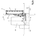
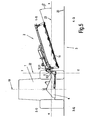
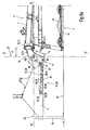
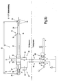
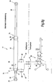
- FIG.1 and Fig.2 show an inventive side mower 2 mounted on a carrier vehicle 1 in a working position and the figures Figure 3 and Figure 4 show an inventive mower 2 mounted to a carrier vehicle 1 in a transport position.
- the side mower 2 consists essentially of a support structure 4, for example for connection to the three-point hydraulic system of a carrier vehicle 4, for example one. Tractor, and a boom 5, which connects the cutter bar 3 with the support structure 4 vertically movable.
- the cantilever arm 5 consists of two cantilever elements 6, 7, wherein the first cantilever element 6 is struck in a pivot joint 8 on the supporting structure 4 in a joint axis extending essentially in the direction of travel F.
- the second boom element 7 is struck in a rotary joint 10 on the first boom element 6 in a substantially upright but at the same time inclined also in the direction of travel F hinge axis 11.
- the second boom element 7 is struck at its free end in the region of the center suspension 18 in a pivot joint 12 on the portal frame 17 in a direction substantially in the direction of travel F axis of articulation.
- the portal frame 17 spans as part of the cutter bar 3, the gear housing 14 of Scheibenmähwerks with its mower discs 15, which are located in a known manner below a protective cover 16.
- the somähwerk 2 is located with respect to the direction of travel F right of the vertical longitudinal center plane 19 of the host vehicle 1, it being equally possible, the side mower 2 left of the vertical longitudinal center plane 19 of the host vehicle. 1 to arrange, and in principle it is also possible that on both sides of the longitudinal center plane 19 each a side mower is arranged.
- the carrier vehicle 1 or the mower 2 according to Fig.1 and Fig.2 an orthogonal coordinate system to be associated with the xyz coordinates whose z-axis is identical to the hinge axis 9 of the rotary joint 8, whose y-axis perpendicularly intersects the hinge axis 9 and whose x-axis is parallel to the horizontal footprint 20 of the host vehicle. It is further assumed that the hinge axis 9 is parallel to the horizontal footprint 20. By definition, the position of the coordinate origin should be located centrally in the pivot bearing of the rotary joint 8.
- the plane spanned by the xy-axis plane is a vertical transverse plane 21
- the plane spanned by the yz-axis a vertical longitudinal plane 22
- Fig.1 shows the carrier vehicle 1 with the side mower 2 in a plan view and Fig.2 seen in a side view from the rear with a view in driving and working direction F in working position.
- the cutter bar 3 In the working position, the cutter bar 3 is below the horizontal plane 23, while the boom 5 is above the horizontal plane 23, and thus in the 1st quadrant.
- the cantilever element 6 a cantilever lever 69, at which in the pivot point 25 a torque arm 27, spaced with the lever arm 56 from a first pivot 10 with a Joint axis 11 is struck.
- the lever 69 and the torque arm 27 lie in a plane approximately parallel to the horizontal plane 23rd
- the lever 69 is part of an orthogonal angle lever 24, which has a first pivot 8 with a first hinge axis 9.
- the hinge axes 9 and 11 in different planes, which include a spatial angle in the range of about 65 ° to 85, preferably about 75 ° to each other.
- the two axes of articulation 8, 11 are spaced apart from one another by the distance dimension 70, so that these axes 8, 11 run through vertical planes spaced apart from this distance dimension 70.
- these two vertical planes extend parallel to one another, which however is not absolutely necessary for realizing the invention, ie they can also assume a diverging course relative to one another.
- the hinge axis 9 of the rotary joint 8 is incorporated in a double lever 71, wherein above the hinge axis 9 as part of the double lever 71, the upper lever 72 extends rigidly connected to the second pivot 10 connects to the second hinge axis 11 with the second lever 69, and wherein below the hinge axis 9, the lower lever 73 extends as a second part of the double lever 71, on which the excavating cylinder 31 and the energy accumulator 40 is hingedly hinged.
- the other end of the torque arm 27 is struck in the hinge point 26 on the boom element 7 and is supported on this.
- the torque arm 27 is simultaneously equipped with an overload protection 28, which is triggered as a force limit in the event of collision of the cutter bar 3 with an obstacle, so that the cutter bar 3 against the driving and working direction F backwards pivots about the hinge axis 11 of the rotary joint 10 and can dodge. Due to an inclination angle of about 5 ° - 25 °, preferably 15 °, the forwardly tilted in the direction of travel hinge axis 11, the cutter bar 3 then pivots on the same side upwards, so that the cutter bar 3 also lifts off the ground.
- Figure 4 show the cutter bar 3 in a transport position, wherein the cantilever arm 5 previously pivoted about the hinge axis 9 (coordinate origin) from the predominantly horizontal working position of the 1st quadrant 1-Q by the pivot angle ⁇ in the predominantly vertical position of the 2nd quadrant 2-Q is.
- Figure 5 shows a headland position in which the mower is pivoted within the 1st quadrant to the pivot angle ⁇ relative to the ground and thus lifted from this.
- the excavating cylinder 31 In the vertical transverse plane 21 (x-y plane), the excavating cylinder 31 is located as an actuator for the pivoting operation.
- the excavating cylinder 31 accommodates two working pistons 33, 35 with their piston rods 34, 36, which lie in an aligned axis 91, which is defined by the connecting straight line between the articulated and articulated points 29, 30.
- the excavating cylinder 31 is thus struck in hinge points 29, 30, wherein it is in the hinge point 29 on the support structure 4 and in the hinge point 30, spaced with a lever arm 55 to the hinge axis 9 of the rotary joint 8 at the boom element 6 and the angle lever 24 is supported.
- the excavating cylinder 31 is capable of applying an upward torque about the hinge axis 9 of the rotary joint 8 to the cutter bar 3 upon appropriate pressurization with a pressurized fluid, whereby it can perform an upward pivotal movement.
- the different switching positions of the controller are represented by the letters abcd, wherein the switch positions b and d can also be locked.
- the positions a and c are flow positions whose positions define the directions of movement of the piston rods 34, 36 determine.
- the position b is the so-called floating position, in which the piston rods 34, 36 can move freely under the action of external forces within the cylinder housing 32, since both pressure chambers 37, 38 are connected to the tank return line T and the pressure line P is locked.
- the position d is the blocking position in which all line connections P; T, A1, B1 are blocked.
- the excavating cylinder 31 takes in its cylinder housing 32 has two working pistons 33; 35, a first piston 33 with a first piston rod 34 and a second piston 35 with a second piston rod 36, in on.
- Inside the cylinder housing 32 are the two working pistons 33, 36 facing each other and between them is a common pressure chamber 38.
- Both piston rods 34, 36 extend oppositely from their associated Working piston 33, 35 averted and emerge from the respective cylinder head 75, 76 end of the cylinder housing 32 and terminate in joint eyes of the hinge points 29, 30th
- the piston rod chamber 80 is aerated or vented through the atmospheric and ambient air by the loading and final ventilators.
- the cutter bar 3 is located on the ground and he can adapt to the current ground profile by transom following the hinge axis 13 of the pivot joint 12 of the center suspension 18 accordingly.
- the boom 5 can move freely about the hinge axis 9 of the rotary joint 8, so that the cutter bar 3 can also adapt to different heights of the soil profile.
- both working pistons 33, 35 and their piston rods 34, 36 float axially freely within the cylinder housing 32, whereby a non-constraining ground adaptation of the cutter bar can take place, which is symbolized by the double arrow 79.
- the distance measure 82 can thus within the limits provided by the mechanical feedback of the musculoskeletal system, the boom 5 and the cutter bar 3, momentarily on the variable situation of the oscillating pivotal movements of the cutter bar 3 about the pivot axis 13 of the pivot joint 12 zwteilungs arthritis to adjust.
- the initial position of the piston rod 34 is characterized in that it fully retracted on the stop 77 of the cylinder head 76 is applied.
- FIG 8D shows the circuit diagram in the valve position c, so that now the hydrostatic pressure of the pump line P at the valve outlet A1 and thus on the wiring harness 81 and the pressure chamber 38 is applied. Due to the hydrostatic pressure in the pressure chamber 38, the working pistons 33, 35 are displaced relative to each other in such a way that the piston distance 74 or the distance 83 of the pivot points 29, 30 increases in the direction of the movement arrow 89.
- the pressurized fluid in the pressure chamber 37 can flow back via the orifice 88 of the throttle check valve 87 via the connecting line 82 to the tank.
- the cutter bar 3 is thus lifted off the ground. and eg in the headland position according to Fig. 5 , or in the transport position according to Figure 3 , or raised in any intermediate position between the working or transport position.
- Fig.8e shows the circuit diagram in the valve position d and thus in the locked position of the control unit 68.
- This locking position can be used in principle in any position of the raised cutter bar 3 to lock the cutter bar 3 in the respective position hydraulically.
- both piston rods 34, 36 are extended into their respective end position and bear against the cylinder heads 75, 76 on the inside of the cylinder housing 32, i.e. on the cylinder heads 75, 76. the piston distance 74 and the distance measure 83 have reached their maximum.
- Fig.8g shows the circuit diagram in the valve position a in the driven starting position at the beginning of the lowering process of the cutter bar 3 from the transport position.
- the hydrostatic pressure of the pressure line P is applied to the connecting line 82 and thus to the pressure chamber 37, and the pressure chamber 38 is connected to the connecting line 81 to the tank return line T.
- the hydrostatic pressure only the working piston 33 with the piston rod 34 can initially move in the direction of the working piston 35, so that the piston distance 74 and the distance dimension 83 are shortened. This causes the cutter bar 3 to initiate a downward pivotal movement, which would then end when the stroke of the power piston 33 is consumed.
- the maximum stroke 84 of the working piston 33 is dimensioned so that the state of the indifferent balance of the cutter bar 3 is overcome during downward pivoting and thus the force of gravity of the cutter bar now as a driving force a torque for downward movement of the cutter bar 3 and the boom 5 exerts.
- This state that gravity is effective as a driving force is, for example, as in Fig. 3a already reached when the cutter bar 3 has moved back from the 2-quadrant into the 1-quadrant 1.-Q.
- the Fig. 6 and Figure 7 show a mowing situation on a slope, the Fig. 6 a downwardly inclined and the Figure 7 showing an upward sloping embankment.
- the excavating cylinder 31 is protected in the interior of the support structure 4 from external unwanted force and pollution influences accommodated. This also allows optimum ground clearance H between the support structure and ground contact surface 20th
- the energy accumulator 41 is designed as a hydraulic cylinder 42 with a working piston 44 and a Kobenstange 45 which is acted upon in the piston bottom side pressure chamber 46 with the pressure of a prestressed hydropneumatic pressure accumulator 93.
- the piston rod 45 is inserted with its extended free end in a surrounding them with play affected shaft tube 47, so that they can move freely in this shaft tube 47 axially displaceable.
- the end of the shaft tube is a joint eye, which is connected at the pivot point 40 with the boom element 6.
- the cylinder housing 43 of the hydraulic cylinder 42 at the same time includes a receiving bore for a stop pin, so that it can be picked up by this, which is the case in the hinge point 39.
- the pivot point 39 is struck against the supporting structure 4, so that the force accumulator 41 or the hydraulic cylinder 42 is also supported on the supporting structure 4 at the same time.
- the piston rod 45 is provided outside the cylinder housing 43 with a transverse bore 48 which is penetrated by a hinge pin 49 which receives a pivotable cap valve 50.
- the distance of the transverse bore 48 from the free end face formed as an annular surface end of the shaft tube 47 is dimensioned so that acts on the piston rod 45 tight-fitting cap flap 50 as a compressive force transmitted force transmission element 51 between the piston rod 45 and shaft tube 47.
- this power transmission element 51 is supported on the one hand on the hinge pin 49 in the transverse bore 48 of the piston rod 45 at this and the other on the annular surface of the shaft tube 47 from.
- the energy accumulator 41 is thus clamped between the hinge points 39 and 40.
- the pivot point 40 is spaced with a lever arm to the hinge axis 9 of the rotary joint 8, so that the effective force in the energy storage 41 via the piston rod 45 can exert on this an upward torque, which tends to lift the cutter bar 3 from the ground, the Torque in its amount is such that it comes only to a bottom pressure relief.
- the size of the preset force or the torque can be set in a known manner by different strong compression of the accumulator bladder of the hydropneumatic accumulator with the hydraulic system of the carrier vehicle.
- a measure of the soil pressure relief is impressed on the reservoir bladder hydraulic biasing pressure, which can be read in a known manner by means of a pressure gauge.
- FIG. 2b shows detail B Fig.2 in an enlarged view with inserted cap flap 50, so that the energy storage device 41 is effective for the bottom contact pressure relief
- the cap flap 50 is connected to a pull rope, which is guided into the driver's cab, and it can be unlocked from the driver's seat and thereby. be put out of action by being so folded around the axis of the hinge pin 49 of the clamp rod 45.
- 8B shows this situation using detail B.
- Figure 8 in an enlarged view, but with raised flap. This serves to make ineffective the ground pressure relief before disconnecting the mower 2 from the carrier vehicle 1 to make the support structure 4 against the angle lever forces.
- the support structure 4 relative to the hinge axis 9 of the rotary joint 8, which results from the energy storage, set torque-free This can be done without the driver having to leave his tractor seat; or without first the hydraulic pressure from the pressure chamber of the accumulator must be drained.
- this not only serves the comfort of the driver but also equally for reducing a risk of injury to the driver when disconnecting the mower when decoupling the hydraulic supply line.
- this includes the advantage that the pressure state in the energy storage 41 is maintained even during the decoupled phase of the carrier vehicle 1, so that the rejoining of the hydraulic connection to the on-board hydraulics for re-compressing and biasing the storage bubble of hydropneumatic accumulator 93 is omitted after re-coupling of the mower 2 to the carrier vehicle 1 and also the set unloading force is stored.
- this advantage of the invention eliminates the otherwise required for each coupling process pressure charging of the pressure chamber of the energy accumulator 41, so that these hydraulic connection neither when coupling nor during uncoupling must be made every time again.
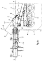
- Figure 10 shows a section Figure 8a in the parking position with inoperative power transmission element 51 by the cap valve 50 is spent in a remote from the piston rod 45 position.
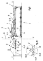
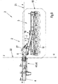
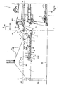
- Figure 11 shows an enlarged section of the transport position of the cutter bar 3 from Fig. 3 , It shows in particular on an enlarged scale the support structure 4, the pivoted angle lever 24, the excavating cylinder 31 with extended piston rod 36, the hydropneumatically prestressed energy storage 41, designed as a hydraulic cylinder 42 with its extended piston rod 45 and the force-free folded down power transmission element 51, the pneumatically prestressed pressure accumulator 93rd , and the shaft tube 47, from which the piston rod 45 has largely moved out. Due to the pivotal movement of the angle lever 24 by the pivot angle ⁇ , the distance between the hinge points 39 and 40 has increased significantly, so that the force transmission element 51 has moved away from the end face 94 of the shaft tube 47.
- the power transmission element 51 has become free of force and in this state, it can easily and with minimum effort of the Piston rod 45 can be folded up by cable pull from the driver's seat into a piston rod far away position.
- This folded-up position of the power transmission element 51 is in Figure 10 shown.
- the piston 44 and the piston rod 45 of the prestressed hydraulic cylinder 42 of the force accumulator 41 moves freely out of the cylinder housing 43 as a result of the accumulator 93 impressed and clamped in this pneumatic pressure of the accumulator, but remains partially in which of the cylinder housing 43 further away shaft tube 47, so that the reception and guidance of the piston rod 45 is maintained by the shaft tube 47.
- the piston 44 is supported in this end position situation of the piston rod 45 with its piston ring surface inside on the cylinder head of the cylinder housing 43, so that thus the piston rod 45 has reached its extended end position, the energy storage device 41 remains biased.
- the power transmission element 51 designed as a cap flap 50 remains folded up, ie in its non-functional position.
- the piston rod 45 now pushes back into the shaft tube 47 without force and while the force transmission element 51 or the cap flap 50 is held up by the cable pull, ie is held in its non-functional position.
- the boom element 7 extends from the pivot 10 backwards against the direction of travel F by an angle s with respect to the vertical transverse plane 21 to the center suspension 18 to the rear, which also has a favorable precondition for the support and the available lever arm 56 of the torque arm 27 creates.
- the angle ⁇ is approximately in the range of 5 ° to 25 °, preferably about 15 °.
- the second boom element with a first support element 57 and the support structure 4 equipped with a complementary support member 58 are designed such that they engage with one another in a form-fitting manner.
- Exemplary of such a positive mating of first and complementary support elements are, for example, pairings such as ball / ball socket, pin / sleeve or pyramid roof / pyramid trough. It is essential to the invention that this pairing of support elements is capable of not only absorbing vertical forces but equally of absorbing horizontal forces resulting from acceleration processes.
- the mower has a display device for the correct altitude of the support structure 4, which can be viewed from the driver's seat.
- the supporting structure should occupy a defined height H with respect to the contact surface 20 of the floor, which can be adjusted with the hydraulic lifting mechanism of the carrier vehicle.
- the orientation angle ⁇ serves as an indirect measure of the height H of the supporting structure.
- the pendulum movement limiting device 59 is equipped with a height adjustment mark 60. This is the detail A in Figure 7 respectively. Fig. 7a refer to.
- the pendulum motion limiting device 59 is on the one hand a part of the boom element 7 of the extension arm 5 and on the other part of the portal frame 17.
- the pendulum motion limiting device 59 consists essentially of a tab 64 which is connected in a hinge connection 62 with the portal frame 17, and at the same time through a slot as a breakthrough of the fork piece 63 passes up through this protrudes. At the upper end of the tab, this has a stopper thickening 65 with a mark in the form of a notch.
- aannaneinstellmarke 60 is fixedly mounted in the form of an arrow.
- the boom element 6 is thus functionally configured as an orthogonal angle lever 24, which is defined by the fact that this two spatially at an angle to each other pivot joints 8,10 are associated with the pivot axes 9,11, and being at the same time the torque arm 27 with the Overload protection 28 is supported.
- the actuating element lifting cylinder 31 and the bottom pressure relief hydraulic cylinder 42 are articulated as an energy storage 41, whereby the angle lever thus exposed to the support structure 4 in different operating situations different load situations, can support the angle lever 24 also assumes the function of a connecting element between the Supporting structure 4 and the second boom element 7 of the
- the design of the angle lever 24 in its multi-functionality is therefore a key inventive importance in terms of its simple and therefore cost-effective design because of its self-consolidating multi-dimensional functionality, because of the improvement in reliability in the event of collision of the mower with an obstacle, and because of the increase in comfort and safety when connecting and disconnecting the mower 1 for the operator or driver of the host vehicle to.
- the invention is illustrated and explained by way of example on a disc mower and it can equally be applied to drum mowers.
Abstract
Description
Die Erfindung betrifft eine Trage- und Führungseinrichtung für eine Mähmaschine insbesondere für ein Seitenmähwerk für den Einsatz in der Grünfutteremte der Landwirtschaft gemäß dem Oberbegriff des unabhängigen Anspruchs 1 (siehe z.B.
Bekannt sind Mähmaschinen als sogenannte Heck- oder Seitenmähwerke mit umlaufenden Mähwerkzeugen, deren Mähklingen frei- bzw. schwenkbeweglich am Umfang der Mähscheiben an einem Zapfen aufgehängt sind. Die Mähklingen werden erst durch die Zentrifugalkraft stabilisiert und mähen das Grünfutter dann ohne Gegenschneide ab. Dabei besteht der eigentliche Mähbalken aus einem untenliegenden Getriebegehäuse, indem die Antriebsorgane, Stirnrad- oder Kegelradzahnradpaarungen gelagert sind und die antriebsseitig mit der Zapfwelle eines Traktors in Verbindung stehen und den ebenfalls in dem Getriebegehäuse gelagerten Mähscheiben. Da die Heckmähwerke seitlich der Spur des Traktors in ihrer Betriebsstellung mähen, ist der Mähbalken am äußeren Ende eines Auslegerarms gelenkig und um eine im wesentlichen in Fahrtrichtung weisende Gelenkachse pendelbar befestigt, damit sich der Mähbalken dem veränderlichen Bodenrelief anpassen kann. Das innere Ende des Auslegerarms ist dabei gelenkig und pendelbar um eine ebenfalls überwiegend in Fahrtrichtung weisende Gelenkachse an einer Tragkonstruktion, welche traktorseitig mit dem Hubwerk der Dreipunkthydraulik eines Traktors verbunden werden kann, verbunden. Zwecks Überführung des Mähbalkens in seine Transportstellung kann der Auslegerarm um die tragbockseitige Gelenkachse aufwärts verschwenkt werden, so dass der Mähbalken ebenfalls überwiegend aufwärts gerichtet in das zulässige Straßentransportprofil überführt wird und damit die zulässige Transportbreite und Transporthöhe für den Straßenverkehr nicht überschritten wird.Mowers are known as so-called rear or side mowers with rotating mowing tools, the mowing blades are freely or pivotally suspended on the circumference of the mowing discs on a pin. The mower blades are only stabilized by the centrifugal force and then mow the green fodder without counter cutting. In this case, the actual mower bar from a lower gear housing by the drive members, spur or bevel gear pairings are stored and the drive side with the PTO of a tractor are in communication and also mounted in the gear housing mower discs. Since the rear mowers mow side of the track of the tractor in its operating position, the cutter bar is hinged at the outer end of a cantilever arm and pendulum mounted around a substantially pointing in the direction of travel hinge axis so that the cutter bar can adapt to the variable ground relief. The inner end of the boom is articulated and pendulum to a likewise predominantly pointing in the direction of travel hinge axis on a supporting structure, which can be connected to the tractor side of the lifting of the three-point hydraulic system of a tractor connected. For the purpose of transferring the cutter bar in its transport position of the boom be pivoted upwards about the support bracket-side hinge axis, so that the cutter bar is also predominantly directed upward in the permissible road transport profile is transferred and thus the permissible transport width and transport height for road traffic is not exceeded.
Heckmähwerke dieser Gattung verfügen zudem über Organe, welche die Stützkraft als Reaktionskraft der Gewichtskraft des Mähbalkens gegenüber dem Boden und damit den Bodenauflagedruck zwischen Mähbalken und Boden im Mähbetrieb reduzieren. Erzeugt wird diese Stützkraftreduzierung, indem der Auslegerarm mit einem aufwärts gerichteten drehenden Drehmoment beaufschlagt wird, welches somit eine ebenfalls aufwärts gerichtete Kraft im Gelenkpunkt zwischen Mähbalken und Auslegerarm erzeugt und die dann der Gewichtskraft des Mähbalkens entgegen gerichtet ist. Das aufwärts gerichtete Drehmoment stützt sich an der Tragkonstruktion und damit am Traktor bzw. Trägerfahrzeug über dessen Räder am Boden ab, so dass dieser Teil der Stützkraftreduzierung des Mähbalkens nunmehr über das Trägerfahrzeug gegenüber dem Boden abgestützt wird. Das aufwärtsgerichtete Drehmoment wird bekanntlich durch krafterzeugende Elemente, wie Zug- oder Druckfedern oder auch vorgespannte hydropneumatische Speicher erzeugt.Rear mowers of this genus also have organs that reduce the supporting force as a reaction force of the weight of the mowing bar relative to the ground and thus the ground contact pressure between cutter bar and ground in mowing. This support force reduction is produced by applying an upward rotational torque to the cantilever arm, which thus generates an upwardly directed force in the pivot point between the mower bar and cantilever arm and which is then directed counter to the weight force of the mowing bar. The upward torque is supported on the support structure and thus on the tractor or carrier vehicle via the wheels on the ground, so that this part of the support force reduction of the cutter bar is now supported by the carrier vehicle relative to the ground. The upward torque is known to be generated by force-generating elements, such as tension or compression springs or biased hydropneumatic storage.
Da mit derartigen Mähwerken mit Seitenausleger immer auch das Kollisionsrisiko mit Grenzsteinen, Kanalisationsdeckeln, Zaunpfählen oder ähnlichem im Mähbetrieb verbunden ist, verfügen derartige Mähwerke über sogenannte Anfahrsicherungen, die der Kollisionskraft nachgeben, so dass der Mähbalken zumindest begrenzt entgegen der Fahrtrichtung durch Verschwenken nach hinten und teils nach oben ausweichen kann, wodurch die Kraftamplitude der Kollisionskraft erheblich gemindert wird.Since with such mowers with jib always the risk of collision with landmarks, sewage covers, fence posts or the like is connected in mowing, such mowers have so-called Anfahrsicherungen yielding to the collision force, so that the cutter bar at least limited against the direction of travel by pivoting backwards and can partially escape upwards, whereby the force amplitude of the collision force is significantly reduced.
Heck oder Seitenmähwerke mit derartigen Auslegerarmen sind in vielfältigen Variationen bekannt und sie können im Heck-, Zwischenachs- oder auch im Frontanbauraum eingesetzt werden.Rear or side mowers with such cantilever arms are known in many variations and they can be used in the rear, Zwischenachs- or in the front mounting space.
Aufgabe der Erfindung ist es, die Anlenkeigenschaften derartiger Trage- und Führungseinrichtungen für Seitenmähwerke sowohl für den Mähbetrieb als den Transportbetrieb funktional einfacher und damit wirtschaftlicher zu gestalten und dabei gleichzeitig den Bedienungskomfort und insbesondere auch die Arbeitssicherheit beim Koppelvorgang, d.h. beim An- und Abbau an das Trägerfahrzeug, zu verbessern.The object of the invention is to make the Anlenkeigenschaften such carrying and guiding devices for side mowers both for the mowing and transporting functionally simpler and thus more economical and at the same time the ease of use and in particular the safety during the coupling process, i. when mounting and dismounting to the carrier vehicle to improve.
Gelöst wird die Aufgabe der Erfindung mit den kennzeichnenden Merkmalen des unabhängigen Anspruchs. Weitere vorteilhafte Ausgestaltungen der Erfindung sind den abhängigen Ansprüchen, der Beschreibung und den Figurendarstellungen zu entnehmen.The object of the invention is achieved with the characterizing features of the independent claim. Further advantageous embodiments of the invention can be found in the dependent claims, the description and the figure representations.
Die Erfindung sieht dabei vor, den Auslegerarm eines Seitenmähwerks wenigstens zweigliedrig derart auszugestalten, so dass das sich zwischen dem Mähbalken wenigstens ein erstes und ein zweites bewegliches Auslegerelement als Teil des Auslegerarms befindet, welche relativ zueinander in einem Drehgelenk miteinander verbunden sind. Das erste bewegliche Auslegerelement ist in einem ersten Drehgelenk mit der Tragkonstruktion, welche das Mähwerk mit dem Trägerfahrzeug verbindet, verbunden, wobei die Gelenkachse etwa in Fahrtrichtung zeigt und damit dieses erste Auslegerelement um eben diese Gelenkachse auf- bzw. abwärts geschwenkt werden kann.The invention provides for the arm of a Seitenmähwerks at least two-part design such that is located between the cutter bar at least a first and a second movable boom member as part of the boom, which relative to each other in a Swivel joint are connected. The first movable boom element is in a first pivot joint with the support structure which connects the mower to the carrier vehicle, wherein the hinge axis points approximately in the direction of travel and thus this first cantilever element can be pivoted about this hinge axis up or down.
Das zweite Auslegerelement schließt sich dem ersten Auslegerelement nach außen gerichtet an und ist in einem Auslegerelement mit dem ersten Auslegerelement verbunden. Die Gelenkachse dieses zweiten Auslegerelements verläuft in der Arbeitsstellung des Mähbetriebs gegenüber dem Boden überwiegend aufrecht, nimmt dabei jedoch in besonders vorteilhafter weise zusätzlich einen nach vorn geneigten Verlauf auf. Das äußere Ende des zweiten Auslegerelements ist dabei etwa mittig der Längserstreckung des Mähbalkens mit diesem gelenkig in einem dritten Drehgelenk verbunden, dessen Gelenkachse wiederum etwa in Fahrtrichtung verläuft.The second cantilever element adjoins the first cantilever element outward and is connected in a cantilever element to the first cantilever element. The hinge axis of this second boom element extends in the working position of the mowing operation relative to the ground predominantly upright, but it takes in a particularly advantageous manner in addition to a forward inclined course. The outer end of the second boom element is approximately centrally connected to the longitudinal extent of the cutter bar with this articulated in a third rotary joint, the hinge axis in turn extends approximately in the direction of travel.
Das zweite Drehgelenk wird dabei von einer Drehmomentstütze überbrückt, welche gleichzeitig in an sich bekannter weise als Anfahr- bzw. Kollisionssicherung ausgestaltet ist, so dass das zweite Auslegerelement samt den daran angelenkten Mähbalken im Kollisionsfall nach hinten um die Gelenkachse des zweiten Drehgelenks verschwenkbar nach hinten ausweichen kann. Durch die gleichzeitig nach vorn geneigte Schwenkachse erfährt der Mähbalken im Falle des Ausweichens und Verschwenkens entgegen der Fahrtrichtung nach hinten gerichtet dabei gleichzeitig eine nach oben gerichtete Bewegungskomponente, so dass der Mähbalken zwangsläufig auch vom Boden abhebt. Dieses wirkt sich besonders vorteilhaft beim Überwinden von geringfügig über das Bodenniveau hinausragenden Hindernissen aus, wie dieses etwa bei vom Grünfutter überwachsenen Grenzsteinen oder Kanaldeckeln der Fall sein kann, so dass das Hindernis dabei völlig überwunden werden kann, ohne dass dieses zwangsläufig zu erheblichen Schäden führt.The second rotary joint is thereby bridged by a torque arm, which is configured in a conventional manner as start-up and collision, so that the second boom element together with the mowing bar hinged thereto in the event of a collision to the rear about the hinge axis of the second pivot pivotally backwards can. By simultaneously tilted forward pivot axis of the mower bar in case of evading and pivoting against the direction of travel directed towards the rear while simultaneously receiving an upward movement component, so that the cutter bar inevitably from the ground takes off. This has a particularly advantageous effect when overcoming slightly above the ground level protruding obstacles, as this may be the case for overgrown boundary fodder or manhole covers, so that the obstacle can be completely overcome without this inevitably leads to considerable damage.
Des weiteren ist das erste Auslegerelement mittels eines ersten Hydraulikzylinders als Stellelement zur Überführung des Mähbalkens in verschiedene Positionen, nämlich der Überführung des Mähbalkens in die Transportposition und umgekehrt in die Arbeitsposition und zum Anheben in die Vorgewendeposition gegenüber der Tragkonstruktion, an dem das Auslegerelement angelenkt ist, abgestützt. Dabei befinden sich besonders vorteilhaft zwei Arbeitskolben in dem Zylindergehäuse des ersten Hydraulikzylinders, wobei die Kolbenstangen des jeweiligen Arbeitskolbens an den Enden des Zylindergehäuses nach außen austreten, und die erste Kolbenstange gelenkig an der Tragkonstruktion und die zweite Kobenstange an dem ersten Auslegerelement gelenkig angeschlagen ist. Dieser erste Hydraulikzylinder überbrückt damit das erste Drehgelenk zwischen der Tragkonstruktion und dem ersten Auslegerelement und er ist dabei so ausgestaltet und in die Kinematik des Bewegungsablaufs der Auslegerkonstruktion integriert, dass er bei dem Aushebevorgang von der Mähposition in die Transportposition bzw. Vorgewendestellung als Druckzylinder arbeitet. Zur Überführung des Mähbalkens in seine Transportposition durchläuft der Mähbalken einen Schwenkwinkel größer als 90° und er wird dann in seiner Endlage von dem ersten Auslegerelement durch einen Anschlag abgestützt, so dass dadurch bedingt die Anfahr- und Kollisionssicherung während der Transportphase des Mähwerks in der Straßen- und Wegefahrt von den Spitzenwerten der Kraftamplituden hervorgerufen durch das Überfahren von Bodenwellen frei gehalten wird, welches ansonsten dazu führen würde, dass die Anfahr- und Kollisionssicherung ungewollt ansprechen und somit ausgelöst werden kann und welches in dieser Phase völlig unerwünscht ist.Furthermore, the first boom element by means of a first hydraulic cylinder as an actuating element for transferring the cutter bar in different positions, namely the transfer of the cutter bar in the transport position and vice versa in the working position and for lifting in the headland position relative to the support structure to which the boom element is articulated, supported. In this case, two working pistons are particularly advantageous in the cylinder housing of the first hydraulic cylinder, wherein the piston rods of the respective working piston at the ends of the cylinder housing to the outside, and the first piston rod articulated to the support structure and the second Kobenstange hinged to the first boom element. This first hydraulic cylinder thus bridges the first pivot between the support structure and the first boom element and it is designed and integrated into the kinematics of the movement sequence of the boom construction that he works as a pressure cylinder in the lifting of the mowing position in the transport position or headland position. For the transfer of the mowing bar in its transport position of the cutter bar passes through a pivot angle greater than 90 ° and it is then supported in its end position by the first cantilever element by a stop, thereby conditionally the start-up and collision during the transport phase of the mower in the road and road trip caused by the peak values of the force amplitudes caused by the driving over bumps is kept free, which would otherwise cause the start-up and collision protection unintentionally respond and thus can be triggered and which is completely undesirable in this phase.
Die Art der Ausgestaltung des ersten Hydraulikzylinders ermöglicht es, den gesamten Steuervorgang, sowohl den der Aushebekinematik als auch den des Mähbetriebs mit lediglich einem Wegeventil gestalten zu können. Die Funktionsweise der Ansteuerung und der Bewegungsablauf sind weiter unten dem Ausführungsbeispiel zu entnehmen.The type of embodiment of the first hydraulic cylinder makes it possible to design the entire control process, both the Aushebekinematik and the mowing operation with only one directional control valve. The operation of the control and the movement are shown below the embodiment.
Die Bodenauflagedruckentlastung nach der Erfindung erfolgt durch einen zweiten Hydraulikzylinder, der durch einen vorgespannten hydropneumatischen Druckspeicher druckbeaufschlagt ist. Auch dieser zweite Hydraulikzylinder überbrückt das erste Drehgelenk und wirkt dabei als Druckzylinder. Die Größe der Vorspannkraft kann dabei mit der Hydraulik des Trägerfahrzeugs variabel eingestellt und dem System bleibend aufgeprägt werden. In besonders vorteilhafter weise kann die Vorspannkraft auch während der Mähfahrt aus dem Führerstand heraus verändert werden.The ground contact pressure relief according to the invention is carried out by a second hydraulic cylinder, which is pressurized by a prestressed hydropneumatic pressure accumulator. This second hydraulic cylinder bridges the first pivot and acts as a pressure cylinder. The size of the biasing force can be variably adjusted with the hydraulic system of the carrier vehicle and permanently impressed on the system. In a particularly advantageous manner, the biasing force can also be changed during the mowing from the cab.
Durch eine ebenfalls vom Fahrersitz aus fernbedienbare Einrichtung kann die Bodenauflagedruckentlastung auf völlig unwirksam gestellt werden, wobei diese bei erneutem Anheben des Mähbalkens in die Transportposition und anschließendem Absenken des Mähbalkens in die Arbeitsstellung automatisch wieder aktiviert, d.h. auf wirksam gestellt wird.By also from the driver's seat from remotely controllable device, the ground contact pressure relief can be made to be completely ineffective, this being on renewed lifting of the mowing bar in the transport position and subsequent lowering of the cutter bar in the working position automatically re-activated, ie is made effective.
Ausgelöst werden kann der Vorgang vom Fahrersitz aus durch die Betätigung eines Seilzugs, der eine Verriegelungsklappe außer Funktion setzt, so dass die Bodenauflagedruckentlastung beim anschließenden Absenken des Mähwerks außer Kraft gesetzt bleibt. Dabei wird keineswegs der hydrostatische Vorspanndruck von dem hydraulischen Entlastungszylinder abgelassen, sondern erfindungsgemäß wird durch die Entriegelung die Kolbenstange infolge des Vorspanndrucks so weit ausgefahren, dass die Kolbenstange buchstäblich ins Leere greift, das heißt, diese wird soweit ausgefahren, dass sie sich innerhalb des Hydraulikzylinders am Kopf des Hydraulikzylinders abstützt. Damit wird diese Stützkraft zur rein inneren Kraft des Hydraulikzylinders selbst, wobei der hydrostatische Vorspanndruck in dem System gefangen bleibt und dem zu Folge aufrechterhalten bleibt.The process can be triggered from the driver's seat by the operation of a cable, which sets a locking flap inoperative, so that the bottom contact pressure relief remains set during the subsequent lowering of the mower. In this case, by no means the hydrostatic biasing pressure is released from the hydraulic unloading cylinder, but according to the invention, the piston rod is extended so far by the unlocking due to the biasing pressure that the piston rod literally reaches into the void, that is, it is extended so far that they are within the hydraulic cylinder on Supported head of the hydraulic cylinder. Thus, this support force becomes the purely internal force of the hydraulic cylinder itself, with the hydrostatic head pressure remaining trapped in the system and consequently maintained.
Dieses beinhaltet den Vorteil, dass die eigentliche Vorspannkraft, hervorgerufen durch den vorgespannten hydropneumatischen Druckspeicher welcher auf die Kolbenstange des Entlastungszylinder einwirkt, von der Tragkonstruktion verschwindet. Dadurch bedingt verschwindet auch das aufwärtsgerichtete Drehmoment, welches entlastend auf den Ausleger und damit entlastend auf den Bodenauflagedruck einwirkt. Damit verschwindet auch das Reaktionsmoment, welches dem aufwärtsgerichteten Drehmoment nach dem Reaktionsprinzip entgegensteht und welches auf die Tragkonstruktion, beispielsweise die des Dreipunktkupplers des Trägerfahrzeugs, einwirkt und welches somit von dem Trägerfahrzeug aufgenommen werden muss, damit das Kräftegleichgewicht als Ganzes aufrecht erhalten wird.This has the advantage that the actual biasing force, caused by the prestressed hydropneumatic pressure accumulator which acts on the piston rod of the relief cylinder, disappears from the supporting structure. As a result, the upward torque disappears, which relieves the load on the boom and relieves pressure on the ground contact pressure. This also disappears the reaction torque which opposes the upward torque according to the reaction principle and which acts on the supporting structure, for example that of the three-point coupler of the carrier vehicle, and which thus of the Carrier must be included so that the balance of power is maintained as a whole.
Der besondere erfindungsgemäße Vorteil besteht darin, dass durch die Außerkraftsetzung der Bodenauflagedruckentlastung das System Tragkonstruktion und Seitenausleger hinsichtlich der von dem zweiten Hydraulikzylinder ausgehenden Kraft kräftefrei gesetzt wird, wodurch beim Abkoppeln des Mähwerks z.B. vom Dreipunktkuppler des Trägerfahrzeugs das Risiko einer Gefährdung des Operators durch Verletzung durch vorgespannte Bauelemente, die noch nicht kräftefrei gemacht wurden, erheblich abgesenkt wird. Dieses gilt auch für Wartungsarbeiten und Reparaturen in Verbindung mit diesem Entlastungssystem.The particular advantage of the invention is that the suspension of the ground pad pressure relief, the system support structure and side arm is set free of force with respect to the outgoing force from the second hydraulic cylinder, whereby, for example, when disconnecting the mower. From the three-point coupler of the host vehicle, the risk of a threat to the operator by injury from biased components that have not yet been made free of forces, is significantly lowered. This also applies to maintenance and repairs related to this relief system.
In einer weiteren Ausgestaltung der Erfindung verfügt das Mähwerk über eine Anzeigevorrichtung über die richtige Höhenlage der von den Unterlenkern des Dreipunktkupplers aufgenommenen Tragkonstruktion des Mähwerks, so dass dadurch der optimale Bewegungsbereich zwischen Auslegerarm und Mähbalken zwecks optimaler Anpassungsfähigkeit des Mähbalkens an Bodenunebenheiten ebenfalls vom Fahrersitz aus leicht eingestellt und überwacht werden kann. Gleichzeitiger Bestandteil dieses Anzeigesystems ist eine Drehwinkelbegrenzung des Mähbalkens um die Drehachse des dritten Drehgelenks, welches durch Anschläge mit Anschlagbedämpfung ausgeführt sein kann.In a further embodiment of the invention, the mower has a display device on the correct altitude of the recorded by the lower links of the three-point coupler support structure of the mower, so that thereby optimally adjusted the optimal range of motion between boom and cutter bar for optimal adaptability of the cutter bar to bumps from the driver's seat and can be monitored. A simultaneous component of this display system is a rotation angle limit of the cutter bar about the axis of rotation of the third rotary joint, which can be carried out by stops with stop damping.
Nähere Einzelheiten der Erfindung sind den nachfolgenden Figurendarstellungen und deren Beschreibungen zu entnehmen.Further details of the invention are given in the following figure representations and their descriptions.
Es zeigen:
- Fig. 1
- zeigt ein Trägerfahrzeug mit Mähwerk in einer Draufsicht in Arbeitsstellung
- Fig. 2
- zeigt ein Trägerfahrzeug mit Mähwerk in einer Ansicht von hinten in Arbeitsstellung
- Fig.2a
- zeigt das Detail B aus
Fig.2 in vergrößerter Darstellung - Fig.3
- zeigt ein Trägerfahrzeug mit Mähwerk in einer Ansicht von hinten in Transportstellung
- Fig. 3a
- zeigt ein Trägerfahrzeug mit Mähwerk in einer Ansicht von hinten in Transportstellung mit 90°-Aushebung
- Fig. 4
- zeigt ein Trägerfahrzeug mit Mähwerk in einer Ansicht von der Seite in Transportstellung
- Fig.5
- zeigt ein Trägerfahrzeug mit angehobenem Mähwerk in einer Ansicht von hinten in Vorgewendestellung
- Fig.6
- zeigt ein Trägerfahrzeug mit einem Mähwerk in einer Ansicht von hinten in einer Arbeitsstellung beim Böschungsmähen mit einer nach unten geneigten Böschung und einem geneigten Mähbalken
- Fig.7
- zeigt ein Trägerfahrzeug mit einem Mähwerk in einer Ansicht von hinten in einer Arbeitsstellung beim Böschungsmähen mit einer nach oben geneigten Böschung und einem geneigten Mähbalken
- Fig.7a
- zeigt einen vergrößerten Ausschnitt aus
Fig.7 - Fig.7b
- zeigt das Detail A aus
Fig.2 in vergrößerter Darstellung - Fig. 8
- zeigt ein vom Trägerfahrzeug abgekoppeltes Mähwerk in einer Ansicht von hinten in Parkstellung
- Fig. 8a
- zeigt einen vergrößerten Ausschnitt aus
Fig.8 - Fig.8b
- zeigt das Detail B aus
Fig.8 in vergrößerter Darstellung mit außer Funktion gesetztem Kraftübertragungselement - Fig. 8c
- zeigt den Hydraulikplan zur Beschaltung des Aushubzylinders in der Betriebsstellung
- Fig. 8d
- zeigt den Hydraulikplan zur Beschaltung des Aushubzylinders in der Phase des Anhebens in die Vorgewende- oder Transportstellung
- Fig. 8e
- zeigt den Hydraulikplan zur Beschaltung des Aushubzylinders in der verriegelten Vorgewendestellung
- Fig.8f
- zeigt den Hydraulikplan zur Beschaltung des Aushubzylinders in der verriegelten Transportstellung
- Fig. 8g
- zeigt den Hydraulikplan zur Beschaltung des Aushubzylinders in der Phase des Absenkens in Richtung Arbeitsstellung
- Fig. 8h
- zeigt den Hydraulikplan zur Beschaltung des Aushubzylinders in der Phase des Absenkens in Richtung Arbeitsstellung im 1.-Quadranten in der etwa 90°-Stellung
- Fig. 9
- zeigt ein vom Trägerfahrzeug abgekoppeltes Mähwerk in einer Ansicht von oben in einer Draufsicht in Parkstellung
- Fig. 9a
- zeigt einen vergrößerten Ausschnitt aus
Fig.9 - Fig. 10
- zeigt einen vergrößerten Ausschnitt aus
Fig.8a - Fig. 11
- zeigt einen vergrößerten Ausschnitt aus
Fig.3
- Fig. 1
- shows a carrier vehicle with mower in a plan view in working position
- Fig. 2
- shows a carrier vehicle with mower in a view from behind in working position
- 2a
- shows detail B
Fig.2 in an enlarged view - Figure 3
- shows a carrier vehicle with mower in a view from behind in transport position
- Fig. 3a
- shows a carrier vehicle with mower in a view from behind in transport position with 90 ° excavation
- Fig. 4
- shows a carrier vehicle with mower in a view from the side in transport position
- Figure 5
- shows a carrier vehicle with raised mower in a view from the rear in headland position
- Figure 6
- shows a carrier vehicle with a mower in a view from behind in a working position when embankment mowing with a sloping slope and a tilted cutter bar
- Figure 7
- shows a carrier vehicle with a mower in a view from behind in a working position when embankment mowing with an upwardly inclined slope and a tilted cutter bar
- 7a
- shows an enlarged section
Figure 7 - Figure 7b
- shows detail A
Fig.2 in an enlarged view - Fig. 8
- shows a decoupled from the carrier vehicle mower in a view from the rear in parking position
- Fig. 8a
- shows an enlarged section
Figure 8 - 8B
- shows detail B
Figure 8 in an enlarged view with disabled power transmission element - Fig. 8c
- shows the hydraulic plan for wiring the excavating cylinder in the operating position
- Fig. 8d
- shows the hydraulic plan for the wiring of the excavating cylinder in the phase of raising in the headland or transport position
- Fig. 8e
- shows the hydraulic plan for wiring the excavating cylinder in the locked headland position
- Fig.8f
- shows the hydraulic plan for wiring the excavating cylinder in the locked transport position
- Fig. 8g
- shows the hydraulic plan for wiring the excavating cylinder in the phase of lowering in the direction of working position
- Fig. 8h
- shows the hydraulic plan for wiring the excavating cylinder in the phase of lowering in the direction of working position in the 1st quadrant in the approximately 90 ° position
- Fig. 9
- shows a decoupled from the carrier vehicle mower in a view from above in a plan view in park position
- Fig. 9a
- shows an enlarged section
Figure 9 - Fig. 10
- shows an enlarged section
Figure 8a - Fig. 11
- shows an enlarged section
Figure 3
Die Figuren
Das Seitenmähwerk 2 besteht im Wesentlichen aus einer Tragkonstruktion 4, beispielsweise zum Anschluss an die Dreipunkthydraulik eines Trägerfahrzeugs 4, beispielsweise eines. Traktors, und einem Auslegerarm 5, der den Mähbalken 3 mit der Tragkonstruktion 4 höhenbeweglich verbindet. Der Auslegerarm 5 besteht aus zwei Auslegerelementen 6,7, wobei das erste Auslegerelement 6 in einem Drehgelenk 8 an der Tragkonstruktion 4 um in eine im Wesentlichen in Fahrtrichtung F verlaufene Gelenkachse angeschlagen ist. Das zweite Auslegerelement 7 ist in einem Drehgelenk 10 an dem ersten Auslegerelement 6 um in eine im Wesentlichen aufrechte jedoch gleichzeitig auch in Fahrtrichtung F geneigte Gelenkachse 11 angeschlagen. Das zweite Auslegerelement 7 ist an seinem freien Ende im Bereich der Mittenaufhängung 18 in einem Drehgelenk 12 an dem Portalrahmen 17 um in eine im Wesentlichen in Fahrtrichtung F verlaufene Gelenkachse angeschlagen. Der Portalrahmen 17 überspannt als Teil des Mähbalkens 3 das Getriebegehäuse 14 des Scheibenmähwerks mit seinen Mähscheiben 15, die sich in bekannter Weise unterhalb einer Schutzabdeckung 16 befinden. In dem dargestellten Ausführungsbeispiel befindet sich das Seitenmähwerk 2 in bezug auf die Fahrtrichtung F rechts der vertikalen Längsmittelebene 19 des Trägerfahrzeugs 1, wobei es genauso möglich ist, das Seitenmähwerk 2 links der vertikalen Längsmittelebene 19 des Trägerfahrzeugs 1 anzuordnen, und prinzipiell ist es ebenso möglich, dass beidseitig der Längsmittelebene 19 je ein Seitenmähwerk angeordnet ist.The
Definitionsgemäß zwecks Beschreibung dieses Ausführungsbeispiels soll dem Trägerfahrzeug 1 bzw. dem Mähwerk 2 gemäß
Wie in
Der Hebel 69 ist Teil eines orthogonalen Winkelhebels 24, der ein erstes Drehgelenk 8 mit einer ersten Gelenkachse 9 aufweist. Dabei liegen die Gelenkachsen 9 und 11 in unterschiedlichen Ebenen, die einen räumlichen Winkel im Bereich von etwa 65° bis 85, vorzugsweise etwa 75°, zueinander einschließen. Wie aus der
Das andere Ende der Drehmomentstütze 27 ist in dem Gelenkpunkt 26 an dem Auslegerelement 7 angeschlagen und stützt sich an diesem ab. Dabei ist die Drehmomentstütze 27 gleichzeitig mit einer Überlastsicherung 28 ausgestattet, die als Kraftbegrenzung im Kollisionsfall des Mähbalkens 3 mit einem Hindernis, ausgelöst wird, so dass der Mähbalken 3 entgegen der Fahr- und Arbeitsrichtung F nach hinten um die Gelenkachse 11 des Drehgelenks 10 zurückschwenkt und ausweichen kann. Bedingt durch einen Neigungswinkel von etwa 5° - 25°, vorzugsweise 15°, der nach vorn in Fahrtrichtung geneigten Gelenkachse 11 schwenkt der Mähbalken 3 dabei dann gleichseitig nach oben aus, so dass der Mähbalken 3 dabei auch vom Boden abhebt.The other end of the
In der vertikalen Querebene 21 (x-y Ebene) befindet sich der Aushubzylinder 31 als Stellglied für den Schwenkvorgang. Der Aushubzylinder 31 nimmt zwei Arbeitskolben 33,35 mit deren Kolbenstangen 34,36 in sich auf, die in einer fluchtenden Achse 91 liegen, welche durch die Verbindungsgeraden zwischen den Gelenk- und Anlenkpunkten 29,30 definiert ist.In the vertical transverse plane 21 (x-y plane), the excavating
Der Aushubzylinder 31 ist somit in Gelenkpunkten 29;30 angeschlagen, wobei er sich im Gelenkpunkt 29 an der Tragkonstruktion 4 und im Gelenkpunkt 30, beabstandet mit einem Hebelarm 55 zur Gelenkachse 9 des Drehgelenks 8, an dem Auslegerelement 6 bzw. dem Winkelhebel 24 abstützt. Damit ist der Aushubzylinder 31 in der Lage bei entsprechender Druckbeaufschlagung mit einem Druckfluid ein aufwärts gerichtetes Drehmoment um die Gelenkachse 9 des Drehgelenks 8 auf den Mähbalken 3 auszuüben, wodurch dieses eine aufwärts gerichtete Schwenkbewegung ausführen kann.The excavating
Anhand der Schaltpläne der
Der Aushubzylinder 31 nimmt in seinem Zylindergehäuse 32 zwei Arbeitskolben 33; 35, einen ersten Arbeitskolben 33 mit einer ersten Kolbenstange 34 und einen zweiten Arbeitskolben 35 mit einer zweiten Kolbenstange 36, in sich auf. Im Inneren des Zylindergehäuses 32 sind die beiden Arbeitskolben 33;36 einander zugewandt und zwischen ihnen liegt ein gemeinsamer Druckraum 38. Beide Kolbenstangen 34;36 erstrecken sich entgegengesetzt von den ihnen zugehörigen Arbeitskolben 33;35 abgewandt und treten aus dem jeweiligen Zylinderkopf 75;76 endseitig des Zylindergehäuses 32 aus und enden in Gelenkaugen der Gelenkpunkte 29;30. Der Kolbenstangenraum 80 wird dabei je nach Bewegungsrichtung des Arbeitskolbens 35 durch den Be- und Endlüfter durch die atmosphärische Umgebung be- oder entlüftet.The excavating
In der Transportstellung sind beide Kolbenstangen 34;36 in ihre jeweilige Endstellung ausgefahren und liegen innenseitig des Zylindergehäuses 32 an den Zylinderköpfen 75;76 an, d.h. der Kolbenabstand 74 und das Abstandsmaß 83 haben Ihr Maximum erreicht.In the transport position, both
Damit der Mähbalken 3 in dieser Abwärtsbewegung keiner unkontrollierten Winkelbeschleunigung ausgesetzt ist, wird das von dem Arbeitskolben 35 verdrängte Druckfluid aus dem Druckraum 38 über eine Drosselblende 86 des Drosselrückschlagventils 85 hinweggeführt. Die Ansteuerung dieses so ausgestalteten Aushubzylinders 31 kann somit erfindungsgemäß für alle Bewegungsabläufe mit lediglich einem doppeltwirkenden Steuergerät (68) durchgeführt werden.So that the
Der dargelegte Steuerungs- und Bewegungsablauf macht den erfinderischen Vorteil des besonders einfachen Steuerungsaufbaus mit nur einem Steuergerät 68 und mit nur einem Aushubzylinder 31, der in erfinderischer Weise durch die gegenseitige Abhängigkeit der beiden Arbeitskolben 33,35 mit deren Kolbenstangen 34,36 an einem gemeinsamen Druckraum 38 anliegen, deutlich.The explained control and movement makes the inventive advantage of particularly simple control structure with only one
Dieses birgt nicht nur kostengünstige und damit wirtschaftliche Vorteile in sich, sondern gleichermaßen ein hohes Maß an inhärenter Sicherheit gegen Fehlbedienungen und deren mögliche Folgen, und daran gekoppelt eine Erhöhung der Arbeitssicherheit, gepaart mit einem höheren Bedienungskomfort für den Fahrer und Operator des Trägerfahrzeugs.This entails not only cost-effective and thus economic advantages in itself, but equally a high degree of inherent security against incorrect operation and their potential consequences, and coupled with an increase in occupational safety, coupled with a higher ease of operation for the driver and operator of the host vehicle.
Die
In besonders vorteilhafter Ausgestaltung der Erfindung ist der Aushubzylinder 31 im Innenraum der Tragkonstruktion 4 geschützt vor äußeren ungewollten Kraft- und Verschmutzungseinflüssen untergebracht. Dieses ermöglicht zudem eine optimale Bodenfreiheit H zwischen Tragkonstruktion und Bodenaufstandsfläche 20.In a particularly advantageous embodiment of the invention, the excavating
Des weiteren greift an dem Auslegerelement 6 ein hydraulischer Kraftspeicher 41 bodendruckentlastend an, wie den
Der Kraftspeicher 41 ist als Hydraulikzylinder 42 mit einem Arbeitskolben 44 und einer Kobenstange 45 ausgebildet, der im kolbenbodenseitigen Druckraum 46 mit dem Druck eines vorgespannten hydropneumatischen Druckspeichers 93 beaufschlagt ist.The energy accumulator 41 is designed as a hydraulic cylinder 42 with a working piston 44 and a
Die Kolbenstange 45 ist mit ihrem verlängerten freien Ende in ein sie umgebendes mit Spiel behaftetes Schaftrohr 47 eingeführt, so dass diese sich ungehindert in dieses Schaftrohr 47 axialverschieblich bewegen kann. Das Ende des Schaftrohrs stellt ein Gelenkauge dar, welches im Gelenkpunkt 40 mit dem Auslegerelement 6 verbunden ist.The
Das Zylindergehäuse 43 des Hydraulikzylinders 42 beinhaltet zugleich eine Aufnahmebohrung für einen Anschlagzapfen, so dass von dieser aufgenommen werden kann, welches im Gelenkpunkt 39 der Fall ist. Der Gelenkpunkt 39 ist an der Tragkonstruktion 4 angeschlagen, so dass sich der Kraftspeicher 41 bzw. der Hydraulikzylinder 42 gleichzeitig auch an der Tragkonstruktion 4 abstützt.The
Die Kolbenstange 45 ist außerhalb des Zylindergehäuses 43 mit einer Querbohrung 48 versehen, die von einem Gelenkbolzen 49 durchsetzt ist, der eine schwenkbewegliche Überwurfklappe 50 aufnimmt. Der Abstand der Querbohrung 48 von dem freien stirnseitigen als Kreisringfläche ausgebildeten Ende des Schaftrohrs 47 ist so bemessen, dass bei an der Kolbenstange 45 eng anliegender Überwurfklappe 50 diese als Druckkraft übertragendes Kraftübertagungselement 51 zwischen Kolbenstange 45 und Schaftrohr 47 fungiert. Dabei stützt sich dieses Kraftübertragungselement 51 zum einen an dem Gelenkbolzen 49 in der Querbohrung 48 der Kolbenstange 45 an dieser und zum anderen an der Kreisringfläche des Schaftrohrs 47 ab.The
Der Kraftspeicher 41 ist somit zwischen den Gelenkpunkten 39 und 40 eingespannt. Der Gelenkpunkt 40 ist mit einem Hebelarm zur Gelenkachse 9 des Drehgelenks 8 beabstandet, so dass die in dem Kraftspeicher 41 wirksame Kraft über die Kolbenstange 45 an diesem ein aufwärts gerichtetes Drehmoment ausüben kann, welches bestrebt ist, den Mähbalken 3 vom Boden abzuheben, wobei das Drehmoment in seinem Betrag so bemessen ist, dass es lediglich zu einer Bodendruckentlastung kommt. Die Größe der voreingestellten Kraft bzw. des Drehmoments kann in bekannter weise durch unterschiedliche starke Kompression der Speicherblase des hydropneumatischen Druckspeichers mit der Hydraulik des Trägerfahrzeugs vorgegeben werden. Ein Maß für die Bodendruckentlastung ist der auf die Speicherblase aufgeprägte hydraulische Vorspanndruck, der in bekannter weise mittels eines Druckmanometers ablesbar ist.The energy accumulator 41 is thus clamped between the hinge points 39 and 40. The
Die Überwurfklappe 50 ist dabei mit einem Zugseil, welches in die Fahrerkabine hineingeführt ist, verbunden und sie kann vom Fahrersitz aus entriegelt und dadurch. außer Funktion gesetzt werden, indem sie damit um die Achse des Gelenkbolzens 49 von der Klobenstange 45 weggeklappt wird.
Dieses dient nicht nur dem Komfort des Fahrers sondern auch gleichermaßen zur Herabsetzung eines Verletzungsrisikos des Fahrers beim Abkoppeln des Mähwerks beim Entkoppeln der hydraulischen Zuleitung. Zudem beinhaltet dieses den Vorteil, dass der Druckzustand im Kraftspeicher 41 auch während der abgekoppelten Phase vom Trägerfahrzeug 1 erhalten bleibt, so dass das Wiederankoppeln der hydraulischen Verbindung an die Bordhydraulik zum erneuten komprimieren und vorspannen der Speicherblase des hydropneumatischen Druckspeichers 93 nach dem Wiederankoppeln des Mähwerks 2 an das Trägerfahrzeug 1 entfällt und zudem die eingestellte Entlastungskraft gespeichert wird. Insbesondere durch diesen Vorteil der Erfindung entfällt die ansonsten bei jedem Kopplungsvorgang erforderliche Druckaufladung des Druckraums des Kraftspeichers 41, so dass auch diese hydraulische Verbindung weder beim Ankoppeln noch beim Abkoppeln jedes Mal erneut vorgenommen werden muss.This not only serves the comfort of the driver but also equally for reducing a risk of injury to the driver when disconnecting the mower when decoupling the hydraulic supply line. In addition, this includes the advantage that the pressure state in the energy storage 41 is maintained even during the decoupled phase of the
Dadurch bedingt kommt beim weiteren Absenken des Mähbalkens 3 das Kraftübertragungselement 51 nicht wieder mit der endseitigen Stirnfläche 94 des Schaftrohrs 47 in Kontakt und dort zur Anlage. Damit aber bleibt die Vorspannkraft V als innere Kraft des Hydraulikzylinders 42 bzw. des Kräftespeichers 41 diesem aufgeprägt, welches bedeutet, das auch im abgestellten bzw. geparkten Zustand des Seitenmähwerks 2 die Vorspannkraft in diesem gespeichert bleibt. Beim späteren Einsatz des Seitenmähwerks 2 nach dem Ankoppeln an das Trägerfahrzeug 1 wird der Mähbalken dann zunächst wieder in die Transportposition hochgeschwenkt, und das Kraftübertragungselement 51 wird dann wieder in seine kraftübertragende Funktionsstellung zurück verbracht d.h. die Überwurfklappe 50 wird dabei nunmehr schwerkraftbetätigt automatisch zurück geklappt.As a result, during further lowering of the
In weiterer vorteilhafter Ausgestaltung der Erfindung fallen die Anschlagpunkte 29 und 39, des Aushubzylinders 31 und des Hydraulikzylinders 42 des Kraftspeichers 41 an der Tragkonstruktion 4 als Gelenkpunkte 29,39 auf einem gemeinsamen Durchgangsbolzen 53 zusammen, welches den Kosten- und Montageaufwand reduziert.In a further advantageous embodiment of the invention, the attachment points 29 and 39, the excavating
Um das Mähwerk 1 möglichst nah am Heck des Trägerfahrzeugs 1 mitführen zu können, erstreckt sich das Auslegerelement 7 ausgehend von dem Drehgelenk 10 rückwärts entgegen der Fahrtrichtung F um einen Winkel s gegenüber der vertikalen Querebene 21 bis hin zur Mittenaufhängung 18 nach hinten, welches zudem eine günstige Vorraussetzung für die Abstützung und den zur Verfügung stehenden Hebelarm 56 der Drehmomentstütze 27 schafft. Der Winkel ε liegt etwa im Bereich von 5° bis 25°, vorzugsweise bei etwa 15°.In order to carry the
Um den Aushubzylinder und die Überlastsicherung in der Transportstellung zu entlasten, wird dieser in der Transportstellung an der Tragkonstruktion 4 abgestützt. Dazu ist das zweite Auslegerelement mit einem ersten Stützelement 57 und die Tragkonstruktion 4 mit einem komplementären Stützelement 58 ausgestattet. Beide Stützelemente 57;58 sind so ausgestaltet, dass sie formschlüssig ineinander greifen. Beispielhaft für eine derartige formschlüssige Paarung von ersten und komplementären Stützelementen sind z.B. Paarungen wie Kugel/Kugelpfanne, Bolzen/Hülse oder Pyramidendach/Pyramidenmulde. Erfindungswesentlich dabei ist, dass diese Paarung von Stützelementen in der Lage ist, nicht nur vertikale Kräfte aufzunehmen, sondern gleichermaßen auch Horizontale Kräfte, die aus Beschleunigungsvorgängen resultieren, aufnehmen kann. Beim Verschwenken des Mähbalkens 3 in die Endlage der Transportstellung gemäß
In einer weiteren Ausgestaltung der Erfindung verfügt das Mähwerk über eine Anzeigevorrichtung für die richtige Höhenlage der Tragkonstruktion 4, welche vom Fahrersitz aus eingesehen werden kann. Damit der Mähbalken eine hinreichend große Beweglichkeit zur Bodenanpassung aufweist soll die Tragkonstruktion eine definierte Höhenlage H gegenüber der Aufstandsfläche 20 des Bodens einnehmen, die mit dem hydraulischen Hubwerk des Trägerfahrzeugs eingestellt werden kann. Dazu dient der Ausrichtungswinkel γ als indirektes Maß für die Höhenlage H der Tragkonstruktion. Zu diesem Zweck ist die Pendelbewegungsbegrenzungseinrichtung 59 mit einer Höheneinstellmarke 60 ausgestattet. Diese ist der Einzelheit A in
In der Normalstellung auf ebenem Boden 20 ist die Höhenlage H der Tragkonstruktion 4 gemäß
Das Auslegerelement 6 ist somit funktional als orthogonaler Winkelhebel 24 ausgestaltet, welcher sich dadurch definiert, dass diesem zwei räumlich in einem Winkel zueinander verlaufende Drehgelenke 8,10 mit deren Schwenkachsen 9,11 zugeordnet sind, und wobei sich an diesem zugleich die Drehmomentstütze 27 mit der Überlastsicherung 28 abstützt. Gleichzeitig sind an diesem Winkelhebel 24 das Stellelement Aushubzylinder 31 und das Bodendruckentlastungselement Hydraulikzylinder 42 als Kraftspeicher 41 angelenkt, wodurch sich der Winkelhebel damit gegenüber der Tragkonstruktion 4 in verschiedenen Betriebssituationen unterschiedlichen Belastungssituationen ausgesetzt, abstützen kann Dabei übernimmt der Winkelhebel 24 zudem die Funktion eines Verbindungselements zwischen der Tragkonstruktion 4 und dem zweiten Auslegerelement 7 des Auslegerarms 5 als Verbindungsglied zum Mähbalken 3 des Seitenmähwerks 1. Der Ausgestaltung des Winkelhebels 24 in seiner Multifunktionalität kommt daher eine zentrale erfinderische Bedeutung hinsichtlich seiner einfachen und damit kostengünstigen Ausgestaltung wegen seiner in sich vereinigenden mehrdimensionalen Funktionalität, wegen der Verbesserung der Betriebssicherheit im Kollisionsfall des Mähwerks mit einem Hindernis, und wegen der Erhöhung des Komforts und der Arbeitssicherheit beim An- und Abkoppeln des Mähwerks 1 für den Operator bzw. Fahrer des Trägerfahrzeugs zu.The
Die Erfindung ist beispielhaft an einem Scheibenmähwerk dargestellt und erläutert und sie lässt sich gleichermaßen auch an Trommelmähwerken anwenden.The invention is illustrated and explained by way of example on a disc mower and it can equally be applied to drum mowers.
- 11
- Trägerfahrzeugcarrier vehicle
- 22
- Mähwerk (Seitenmähwerk)Mower (side mower)
- 33
- Mähbalken (Mäheinrichtung)Mower bar (mower)
- 44
- Tragkonstruktionsupporting structure
- 55
- Auslegerarmboom
- 66
- erstes Auslegerelementfirst boom element
- 77
- zweites Auslegerelementsecond boom element
- 88th
- Drehgelenkswivel
- 99
- Gelenkachsejoint axis
- 1010
- Drehgelenkswivel
- 1111
- Gelenkachsejoint axis
- 1212
- Drehgelenkswivel
- 1313
- Gelenkachsejoint axis
- 1414
- Getriebegehäusegearbox
- 1515
- Mähscheibe (Schneidorgan)Mower disc (cutting element)
- 1616
- Schutzabdeckungprotective cover
- 1717
- Portalrahmenportal frame
- 1818
- Mittenaufhängungcenter suspension
- 1919
- vertikale Längsmittelebene des Trägerfahrzeugsvertical longitudinal center plane of the carrier vehicle
- 2020
- horizontale Aufstandsflächehorizontal footprint
- 2121
- vertikale Querebene (x-y-Ebene)vertical transverse plane (x-y-plane)
- 2222
- vertikale Längsebene (y-z-Ebene)vertical longitudinal plane (y-z-plane)
- 2323
- Horizontalebene (x-z-Ebene)Horizontal plane (x-z-plane)
- 2424
- orthogonaler Winkelhebelorthogonal bell crank
- 2525
- Gelenkpunktfulcrum
- 2626
- Gelenkpunktfulcrum
- 2727
- Drehmomentstützetorque arm
- 2828
- ÜberlastsicherungOverload protection
- 2929
- Gelenkpunkt (Anlenkpunkt)Articulation point (articulation point)
- 3030
- Gelenkpunkt (Anlenkpunkt)Articulation point (articulation point)
- 3131
- Aushubzylinderlifting cylinder
- 3232
- Zylindergehäusecylinder housing
- 3333
- erster Arbeitskolbenfirst working piston
- 3434
- erste Kolbenstangefirst piston rod
- 3535
- zweiter Arbeitskolbensecond working piston
- 3636
- zweite Kolbenstangesecond piston rod
- 3737
- erster Druckraumfirst pressure chamber
- 3838
- zweiter Druckraumsecond pressure chamber
- 3939
- Gelenkpunktfulcrum
- 4040
- Gelenkpunktfulcrum
- 4141
- Kraftspeicherpower storage
- 4242
- Hydraulikzylinderhydraulic cylinders
- 4343
- Zylindergehäusecylinder housing
- 4444
- Arbeitskolbenworking piston
- 4545
- Kolbenstangepiston rod
- 4646
- erster Druckraumfirst pressure chamber
- 4747
- Schaftrohrsteerer
- 4848
- Querbohrungcross hole
- 4949
- Gelenkbolzenhinge pins
- 5050
- ÜberwurfklappeUnion flap
- 5151
- KraftübertragungselementPower transmission element
- 5252
- Gelenkpunktfulcrum
- 5353
- DurchgangsbolzenThrough bolt
- 5454
- Hebelarmlever arm
- 5555
- Hebelarmlever arm
- 5656
- Hebelarmlever arm
- 5757
- Stützelementsupport element
- 5858
- komplementäres Stützelementcomplementary support element
- 5959
- PendelbewegungsbegrenzungseinrichtungPendulum motion limiting device
- 6060
- HöheneinstellmarkeHöheneinstellmarke
- 6161
- Mitnehmerlaschedriver link
- 6262
- Gelenkverbindungarticulation
- 6363
- Gabelstückforked piece
- 6464
- Lascheflap
- 6565
- Anschlagverdickungstop thickening
- 6666
- Kerbe der MarkierungNotch of the mark
- 6767
- Pfeilspitzearrowhead
- 6868
- doppelwirkendes Steuergerät (Wegeventil)double-acting control unit (directional control valve)
- 6969
- Hebellever
- 7070
- AbstandsmaßPitch
- 7171
- Doppelhebeldouble lever
- 7272
- oberer Hebelupper lever
- 7373
- unterer Hebellower lever
- 7474
- Kolbenabstandpiston clearance
- 7575
- Zylinderkopfcylinder head
- 7676
- Zylinderkopfcylinder head
- 7777
- Anschlagattack
- 7878
- Be- und EndlüfterLoading and final fan
- 7979
- Doppelpfeildouble arrow
- 8080
- KolbenstangenraumPiston rod space
- 8181
- Verbindungsleitungconnecting line
- 8282
- Verbindungsleitungconnecting line
- 8383
- AbstandsmaßPitch
- 8484
- Hubstroke
- 8585
- DrosselrückschlagventilSpeed Controller
- 8686
- Drosselblendeorifice
- 8787
- DrosselrückschlagventilSpeed Controller
- 8888
- Drosselblendeorifice
- 8989
- Bewegungspfeilmovement arrow
- 9090
- Bewegungspfeilmovement arrow
- 9191
- Achseaxis
- 9292
- Wirkungslinieline of action
- 9393
- Druckspeicheraccumulator
- 9494
- Stirnflächeface
- FF
- Fahrt- und ArbeitsrichtungDriving and working direction
- HH
- Höhenlagealtitude
- PP
- Druckleitungpressure line
- TT
- Tankleitungtank line
- A1A1
- Verbindungsleitungconnecting line
- B1B1
- Verbindungsleitungconnecting line
- VV
- Vorspannkraftpreload force
- 1-Q1-Q
- 1.-Quadrant1. Quadrant
- 2-Q2-Q
- 2.-Quadrant2. Quadrant
- 3-Q3-Q
- 3.-Quadrant3. Quadrant
- 4-Q4-Q
- 4.-Quadrant4. Quadrant
- αα
- Schwenkwinkelswivel angle
- ββ
- Schwenkwinkelswivel angle
- γγ
- Schwenkwinkelswivel angle
- δδ
- Schwenkwinkelswivel angle
- εε
- Winkelangle
- γγ
- Pendelwinkelswing angle
- δδ
- mittlere Pendelwinkelmean pendulum angle
Claims (11)
- A. mowing machine, in particular a side mowing machine for mounting to a lifting arrangement or an agricultural carrier vehicle, comprising a mowing device which in a working and operative position is guided laterally by the agricultural carrier vehicle and which includes a number of cutting members carrying mowing blades rotating about a vertical axis, comprising a carrier and guide device as a connecting member between the mowing machine and the carrier vehicle, with a pivotable boom arm for pivotal movement of the mowing device from an approximately horizontal working and operative position into a lifted field headland position and/or transport position, and an adjusting member for pivoting the mowing device from a working position near the ground into a lifted field headland or transport position further from the ground, characterised in that the carrier and guide device includes an adjusting member in the form of a pressure fluid-operated lifting cylinder (31) having two mutually dependent working pistons (33; 35) which enclose a common pressure chamber (38) between them.
- A mowing machine according to claim 1 characterised in that the working pistons (33; 35) are disposed in an aligned axis (91) on the straight line connecting the pivotal mounting points (29, 30).
- A mowing machine according to claim 1 and claim 2 characterised in that one of the two working pistons (33; 35) can be pressure-actuated in double-acting relationship and the respective other working piston (33 or 35) can be pressure-actuated in single-acting relationship.
- A mowing machine according to claims 1 to 3 characterised in that both working pistons (33; 35) are accommodated by a cylinder housing.
- A mowing machine according to claims 1 to 4 characterised in that the lifting cylinder (31) operates as a pressure cylinder in the upwardly directed pivotal movement of the mowing cutter bar (3).
- A mowing machine according to claims 1 to 5 characterised in that during the upwardly directed pivotal movement of the mowing cutter bar (3) the common pressure chamber (38) of the two working pistons (33; 35) of the lifting cylinder (31) is connected in pressurised relationship to the pressure line (P).
- A mowing machine according to claims 1 to 4 characterised in that in the downwardly directed phase of the lowering movement of the mowing cutter bar (3) the pressure chamber (37) at the piston rod side is hydrostatically pressure-actuated and the common pressure chamber (38) of both working pistons (33; 35) is connected to the tank line (T).
- A mowing machine according to claims 1 to 7 characterised in that the control device (68) and the lifting cylinder (31) are connected together by two connecting lines (81, 82).
- A mowing machine according to claims 1 to 8 characterised in that at least one respective throttle orifice (86; 88) is associated with both connecting lines (81,82).
- A mowing machine according to claims 1 to 9 characterised in that a respective throttle check valve (85; 87) is associated with both connecting lines (81, 82).
- A mowing machine according to claims 1 to 10 characterised in that the hydraulic lifting cylinder (31) can be controlled by only one double-acting control device (68).
Applications Claiming Priority (1)
| Application Number | Priority Date | Filing Date | Title |
|---|---|---|---|
| DE102005061976A DE102005061976A1 (en) | 2005-12-23 | 2005-12-23 | mower |
Publications (3)
| Publication Number | Publication Date |
|---|---|
| EP1800529A1 EP1800529A1 (en) | 2007-06-27 |
| EP1800529B1 true EP1800529B1 (en) | 2008-11-12 |
| EP1800529B2 EP1800529B2 (en) | 2012-05-30 |
Family
ID=37882245
Family Applications (1)
| Application Number | Title | Priority Date | Filing Date |
|---|---|---|---|
| EP06025318A Active EP1800529B2 (en) | 2005-12-23 | 2006-12-07 | Mowing machine |
Country Status (4)
| Country | Link |
|---|---|
| EP (1) | EP1800529B2 (en) |
| AT (1) | ATE413800T1 (en) |
| DE (3) | DE102005061976A1 (en) |
| DK (1) | DK1800529T4 (en) |
Cited By (1)
| Publication number | Priority date | Publication date | Assignee | Title |
|---|---|---|---|---|
| EP2174538A1 (en) | 2008-10-08 | 2010-04-14 | Claas Saulgau Gmbh | Working device, in particular for rear or front attachment to an agricultural vehicle |
Families Citing this family (6)
| Publication number | Priority date | Publication date | Assignee | Title |
|---|---|---|---|---|
| DE202007014320U1 (en) | 2007-10-12 | 2007-12-06 | Fella-Werke Gmbh & Co. Kg | Supporting and guiding device for an agricultural machine |
| DK3086632T3 (en) * | 2013-12-23 | 2018-05-28 | Kverneland Group Kerteminde As | AGRICULTURAL MACHINERY |
| DE102014104379A1 (en) | 2014-03-28 | 2015-10-01 | Claas Saulgau Gmbh | Implement for coupling to an agricultural machine |
| FR3037211B1 (en) * | 2015-06-15 | 2018-01-19 | Kuhn Sa | AGRICULTURAL MACHINE WITH A GROUP OF TOOLS THAT MAY BE LATERALLY DEPORTED |
| DE202016002490U1 (en) * | 2016-04-18 | 2016-05-25 | Maschinenfabrik Bernard Krone GmbH & Co. KG | Agricultural work machine with improved transport safety |
| IT201700010720A1 (en) | 2017-02-01 | 2018-08-01 | Roc S R L | AGRICULTURAL MACHINE |
Family Cites Families (6)
| Publication number | Priority date | Publication date | Assignee | Title |
|---|---|---|---|---|
| FR2160378A1 (en) † | 1972-09-27 | 1973-06-29 | Poclain Sa | |
| NL7604451A (en) † | 1976-04-27 | 1977-10-31 | Texas Industries Inc | MOWING MACHINE. |
| DE19534695C2 (en) † | 1995-09-19 | 1998-12-24 | Hans Grenzebach | Rear mower that can be attached to a tractor |
| FR2794934B1 (en) * | 1999-06-17 | 2001-08-10 | Kuhn Sa | AGRICULTURAL MACHINE OF THE MOWER OR MOWER CONDITIONER TYPE COMPRISING A SHOCK ABSORBER |
| DE10011730C2 (en) † | 2000-03-10 | 2002-01-31 | Krone Bernhard Gmbh Maschf | mower |
| DE50200957D1 (en) † | 2002-04-05 | 2004-10-14 | Festo Ag & Co | Fluid operated drive device |
-
2005
- 2005-12-23 DE DE102005061976A patent/DE102005061976A1/en not_active Ceased
- 2005-12-23 DE DE202005021551U patent/DE202005021551U1/en not_active Expired - Lifetime
-
2006
- 2006-12-07 AT AT06025318T patent/ATE413800T1/en active
- 2006-12-07 DK DK06025318.4T patent/DK1800529T4/en active
- 2006-12-07 DE DE502006002057T patent/DE502006002057D1/en active Active
- 2006-12-07 EP EP06025318A patent/EP1800529B2/en active Active
Cited By (2)
| Publication number | Priority date | Publication date | Assignee | Title |
|---|---|---|---|---|
| EP2174538A1 (en) | 2008-10-08 | 2010-04-14 | Claas Saulgau Gmbh | Working device, in particular for rear or front attachment to an agricultural vehicle |
| DE102009023956A1 (en) | 2008-10-08 | 2010-04-15 | Claas Saulgau Gmbh | Working device, in particular for rear-side or front-side arrangement on an agricultural vehicle |
Also Published As
| Publication number | Publication date |
|---|---|
| DE202005021551U1 (en) | 2008-11-27 |
| EP1800529B2 (en) | 2012-05-30 |
| ATE413800T1 (en) | 2008-11-15 |
| EP1800529A1 (en) | 2007-06-27 |
| DE102005061976A1 (en) | 2007-07-12 |
| DE502006002057D1 (en) | 2008-12-24 |
| DK1800529T4 (en) | 2012-09-10 |
| DK1800529T3 (en) | 2009-03-16 |
Similar Documents
| Publication | Publication Date | Title |
|---|---|---|
| EP1800529B1 (en) | Mowing machine | |
| EP2042011B1 (en) | Work vehicle with fitting device | |
| EP0182091B1 (en) | Power lift for a hoisting device | |
| EP1438886B1 (en) | Coupling device | |
| EP1348324B1 (en) | Mower comprising coupled, articulated cutter bars | |
| EP2186713B1 (en) | Ballast device and agricultural vehicle with such device | |
| US20110298197A1 (en) | Adjustable and Foldable V-Shaped Hay Rake | |
| EP3075246B1 (en) | Agricultural machine and security method | |
| EP1205097B1 (en) | Self-levelling forkhead and towing device unit | |
| EP1514463A1 (en) | Device for coupling a working tool to a vehicle | |
| EP1800528B1 (en) | Mowing machine | |
| EP2042410B1 (en) | Agricultural vehicle | |
| EP1800530B1 (en) | Mowing machine | |
| DE19953380A1 (en) | Self-propelled mower unit | |
| DE3030417C2 (en) | Notching device | |
| DE3448426C3 (en) | Agricultural machine | |
| DE3444412C2 (en) | ||
| AT502053B1 (en) | MOUNTING DEVICE FOR A LANDING MACHINE | |
| EP0903076B1 (en) | Collision protection for drawn agricultural working implement | |
| DE102009029037A1 (en) | Forest trailer for storing and delivering woods, has hydraulic pump connected with rotary shaft, which is driven by drive journal of tractor, where hydraulic pump is arranged in hollow section of hitch drawbar | |
| DE2614517C3 (en) | Locking device for the lifting shaft of a hydraulic power lift of agricultural tractors with three-point hitch | |
| EP1040751A2 (en) | Self-propelled mower | |
| DE1557673C (en) | Auxiliary lifting device for implements that can be lifted out of tractors via the three-point hitch, in particular tillage implements | |
| DE19960659A1 (en) | Overload safety release device for front-mounted mowing machine on tractor has hinge to allow each mowing cutter to fold backwards with fracture of bolt on imposition of excessive load | |
| DE102019135685A1 (en) | Trailers, in particular forestry trailers |
Legal Events
| Date | Code | Title | Description |
|---|---|---|---|
| PUAI | Public reference made under article 153(3) epc to a published international application that has entered the european phase |
Free format text: ORIGINAL CODE: 0009012 |
|
| AK | Designated contracting states |
Kind code of ref document: A1 Designated state(s): AT BE BG CH CY CZ DE DK EE ES FI FR GB GR HU IE IS IT LI LT LU LV MC NL PL PT RO SE SI SK TR |
|
| AX | Request for extension of the european patent |
Extension state: AL BA HR MK YU |
|
| 17P | Request for examination filed |
Effective date: 20071227 |
|
| AKX | Designation fees paid |
Designated state(s): AT BE BG CH CY CZ DE DK EE ES FI FR GB GR HU IE IS IT LI LT LU LV MC NL PL PT RO SE SI SK TR |
|
| GRAP | Despatch of communication of intention to grant a patent |
Free format text: ORIGINAL CODE: EPIDOSNIGR1 |
|
| GRAS | Grant fee paid |
Free format text: ORIGINAL CODE: EPIDOSNIGR3 |
|
| GRAA | (expected) grant |
Free format text: ORIGINAL CODE: 0009210 |
|
| AK | Designated contracting states |
Kind code of ref document: B1 Designated state(s): AT BE BG CH CY CZ DE DK EE ES FI FR GB GR HU IE IS IT LI LT LU LV MC NL PL PT RO SE SI SK TR |
|
| REG | Reference to a national code |
Ref country code: GB Ref legal event code: FG4D Free format text: NOT ENGLISH |
|
| REG | Reference to a national code |
Ref country code: CH Ref legal event code: EP |
|
| REG | Reference to a national code |
Ref country code: IE Ref legal event code: FG4D Free format text: LANGUAGE OF EP DOCUMENT: GERMAN |
|
| REF | Corresponds to: |
Ref document number: 502006002057 Country of ref document: DE Date of ref document: 20081224 Kind code of ref document: P |
|
| REG | Reference to a national code |
Ref country code: DK Ref legal event code: T3 |
|
| LTIE | Lt: invalidation of european patent or patent extension |
Effective date: 20081112 |
|
| PG25 | Lapsed in a contracting state [announced via postgrant information from national office to epo] |
Ref country code: LT Free format text: LAPSE BECAUSE OF FAILURE TO SUBMIT A TRANSLATION OF THE DESCRIPTION OR TO PAY THE FEE WITHIN THE PRESCRIBED TIME-LIMIT Effective date: 20081112 Ref country code: ES Free format text: LAPSE BECAUSE OF FAILURE TO SUBMIT A TRANSLATION OF THE DESCRIPTION OR TO PAY THE FEE WITHIN THE PRESCRIBED TIME-LIMIT Effective date: 20090223 |
|
| PG25 | Lapsed in a contracting state [announced via postgrant information from national office to epo] |
Ref country code: SI Free format text: LAPSE BECAUSE OF FAILURE TO SUBMIT A TRANSLATION OF THE DESCRIPTION OR TO PAY THE FEE WITHIN THE PRESCRIBED TIME-LIMIT Effective date: 20081112 Ref country code: PL Free format text: LAPSE BECAUSE OF FAILURE TO SUBMIT A TRANSLATION OF THE DESCRIPTION OR TO PAY THE FEE WITHIN THE PRESCRIBED TIME-LIMIT Effective date: 20081112 Ref country code: IS Free format text: LAPSE BECAUSE OF FAILURE TO SUBMIT A TRANSLATION OF THE DESCRIPTION OR TO PAY THE FEE WITHIN THE PRESCRIBED TIME-LIMIT Effective date: 20090312 Ref country code: FI Free format text: LAPSE BECAUSE OF FAILURE TO SUBMIT A TRANSLATION OF THE DESCRIPTION OR TO PAY THE FEE WITHIN THE PRESCRIBED TIME-LIMIT Effective date: 20081112 Ref country code: LV Free format text: LAPSE BECAUSE OF FAILURE TO SUBMIT A TRANSLATION OF THE DESCRIPTION OR TO PAY THE FEE WITHIN THE PRESCRIBED TIME-LIMIT Effective date: 20081112 |
|
| BERE | Be: lapsed |
Owner name: CLAAS SAULGAU G.M.B.H. Effective date: 20081231 |
|
| REG | Reference to a national code |
Ref country code: IE Ref legal event code: FD4D |
|
| PG25 | Lapsed in a contracting state [announced via postgrant information from national office to epo] |
Ref country code: EE Free format text: LAPSE BECAUSE OF FAILURE TO SUBMIT A TRANSLATION OF THE DESCRIPTION OR TO PAY THE FEE WITHIN THE PRESCRIBED TIME-LIMIT Effective date: 20081112 Ref country code: IE Free format text: LAPSE BECAUSE OF FAILURE TO SUBMIT A TRANSLATION OF THE DESCRIPTION OR TO PAY THE FEE WITHIN THE PRESCRIBED TIME-LIMIT Effective date: 20081112 Ref country code: BG Free format text: LAPSE BECAUSE OF FAILURE TO SUBMIT A TRANSLATION OF THE DESCRIPTION OR TO PAY THE FEE WITHIN THE PRESCRIBED TIME-LIMIT Effective date: 20090212 Ref country code: RO Free format text: LAPSE BECAUSE OF FAILURE TO SUBMIT A TRANSLATION OF THE DESCRIPTION OR TO PAY THE FEE WITHIN THE PRESCRIBED TIME-LIMIT Effective date: 20081112 Ref country code: MC Free format text: LAPSE BECAUSE OF NON-PAYMENT OF DUE FEES Effective date: 20081231 |
|
| PLBI | Opposition filed |
Free format text: ORIGINAL CODE: 0009260 |
|
| PG25 | Lapsed in a contracting state [announced via postgrant information from national office to epo] |
Ref country code: SE Free format text: LAPSE BECAUSE OF FAILURE TO SUBMIT A TRANSLATION OF THE DESCRIPTION OR TO PAY THE FEE WITHIN THE PRESCRIBED TIME-LIMIT Effective date: 20090212 Ref country code: PT Free format text: LAPSE BECAUSE OF FAILURE TO SUBMIT A TRANSLATION OF THE DESCRIPTION OR TO PAY THE FEE WITHIN THE PRESCRIBED TIME-LIMIT Effective date: 20090413 Ref country code: CZ Free format text: LAPSE BECAUSE OF FAILURE TO SUBMIT A TRANSLATION OF THE DESCRIPTION OR TO PAY THE FEE WITHIN THE PRESCRIBED TIME-LIMIT Effective date: 20081112 |
|
| 26 | Opposition filed |
Opponent name: OCTROOIBUREAU VAN DER LELY N.V. Effective date: 20090807 |
|
| PLAX | Notice of opposition and request to file observation + time limit sent |
Free format text: ORIGINAL CODE: EPIDOSNOBS2 |
|
| PG25 | Lapsed in a contracting state [announced via postgrant information from national office to epo] |
Ref country code: SK Free format text: LAPSE BECAUSE OF FAILURE TO SUBMIT A TRANSLATION OF THE DESCRIPTION OR TO PAY THE FEE WITHIN THE PRESCRIBED TIME-LIMIT Effective date: 20081112 Ref country code: BE Free format text: LAPSE BECAUSE OF NON-PAYMENT OF DUE FEES Effective date: 20081231 |
|
| NLR1 | Nl: opposition has been filed with the epo |
Opponent name: OCTROOIBUREAU VAN DER LELY N.V. |
|
| PLBB | Reply of patent proprietor to notice(s) of opposition received |
Free format text: ORIGINAL CODE: EPIDOSNOBS3 |
|
| PG25 | Lapsed in a contracting state [announced via postgrant information from national office to epo] |
Ref country code: LU Free format text: LAPSE BECAUSE OF NON-PAYMENT OF DUE FEES Effective date: 20081207 Ref country code: HU Free format text: LAPSE BECAUSE OF FAILURE TO SUBMIT A TRANSLATION OF THE DESCRIPTION OR TO PAY THE FEE WITHIN THE PRESCRIBED TIME-LIMIT Effective date: 20090513 Ref country code: CY Free format text: LAPSE BECAUSE OF FAILURE TO SUBMIT A TRANSLATION OF THE DESCRIPTION OR TO PAY THE FEE WITHIN THE PRESCRIBED TIME-LIMIT Effective date: 20081112 |
|
| PG25 | Lapsed in a contracting state [announced via postgrant information from national office to epo] |
Ref country code: TR Free format text: LAPSE BECAUSE OF FAILURE TO SUBMIT A TRANSLATION OF THE DESCRIPTION OR TO PAY THE FEE WITHIN THE PRESCRIBED TIME-LIMIT Effective date: 20081112 |
|
| PG25 | Lapsed in a contracting state [announced via postgrant information from national office to epo] |
Ref country code: GR Free format text: LAPSE BECAUSE OF FAILURE TO SUBMIT A TRANSLATION OF THE DESCRIPTION OR TO PAY THE FEE WITHIN THE PRESCRIBED TIME-LIMIT Effective date: 20090213 |
|
| PG25 | Lapsed in a contracting state [announced via postgrant information from national office to epo] |
Ref country code: IT Free format text: LAPSE BECAUSE OF FAILURE TO SUBMIT A TRANSLATION OF THE DESCRIPTION OR TO PAY THE FEE WITHIN THE PRESCRIBED TIME-LIMIT Effective date: 20081112 |
|
| REG | Reference to a national code |
Ref country code: CH Ref legal event code: PL |
|
| GBPC | Gb: european patent ceased through non-payment of renewal fee |
Effective date: 20101207 |
|
| PG25 | Lapsed in a contracting state [announced via postgrant information from national office to epo] |
Ref country code: CH Free format text: LAPSE BECAUSE OF NON-PAYMENT OF DUE FEES Effective date: 20101231 Ref country code: LI Free format text: LAPSE BECAUSE OF NON-PAYMENT OF DUE FEES Effective date: 20101231 |
|
| PG25 | Lapsed in a contracting state [announced via postgrant information from national office to epo] |
Ref country code: GB Free format text: LAPSE BECAUSE OF NON-PAYMENT OF DUE FEES Effective date: 20101207 |
|
| PUAH | Patent maintained in amended form |
Free format text: ORIGINAL CODE: 0009272 |
|
| STAA | Information on the status of an ep patent application or granted ep patent |
Free format text: STATUS: PATENT MAINTAINED AS AMENDED |
|
| 27A | Patent maintained in amended form |
Effective date: 20120530 |
|
| AK | Designated contracting states |
Kind code of ref document: B2 Designated state(s): AT BE BG CH CY CZ DE DK EE ES FI FR GB GR HU IE IS IT LI LT LU LV MC NL PL PT RO SE SI SK TR |
|
| REG | Reference to a national code |
Ref country code: DE Ref legal event code: R102 Ref document number: 502006002057 Country of ref document: DE Effective date: 20120530 |
|
| REG | Reference to a national code |
Ref country code: NL Ref legal event code: T3 |
|
| REG | Reference to a national code |
Ref country code: DK Ref legal event code: T4 |
|
| PG25 | Lapsed in a contracting state [announced via postgrant information from national office to epo] |
Ref country code: LV Free format text: LAPSE BECAUSE OF FAILURE TO SUBMIT A TRANSLATION OF THE DESCRIPTION OR TO PAY THE FEE WITHIN THE PRESCRIBED TIME-LIMIT Effective date: 20120530 |
|
| REG | Reference to a national code |
Ref country code: FR Ref legal event code: PLFP Year of fee payment: 10 |
|
| REG | Reference to a national code |
Ref country code: FR Ref legal event code: PLFP Year of fee payment: 11 |
|
| REG | Reference to a national code |
Ref country code: FR Ref legal event code: PLFP Year of fee payment: 12 |
|
| PGFP | Annual fee paid to national office [announced via postgrant information from national office to epo] |
Ref country code: NL Payment date: 20211221 Year of fee payment: 16 |
|
| REG | Reference to a national code |
Ref country code: NL Ref legal event code: MM Effective date: 20230101 |
|
| PG25 | Lapsed in a contracting state [announced via postgrant information from national office to epo] |
Ref country code: NL Free format text: LAPSE BECAUSE OF NON-PAYMENT OF DUE FEES Effective date: 20230101 |
|
| PGFP | Annual fee paid to national office [announced via postgrant information from national office to epo] |
Ref country code: FR Payment date: 20231221 Year of fee payment: 18 Ref country code: DK Payment date: 20231227 Year of fee payment: 18 Ref country code: DE Payment date: 20231214 Year of fee payment: 18 Ref country code: AT Payment date: 20231221 Year of fee payment: 18 |