EP1785100A1 - Surgical sickle needle and method of using it - Google Patents
Surgical sickle needle and method of using it Download PDFInfo
- Publication number
- EP1785100A1 EP1785100A1 EP06023334A EP06023334A EP1785100A1 EP 1785100 A1 EP1785100 A1 EP 1785100A1 EP 06023334 A EP06023334 A EP 06023334A EP 06023334 A EP06023334 A EP 06023334A EP 1785100 A1 EP1785100 A1 EP 1785100A1
- Authority
- EP
- European Patent Office
- Prior art keywords
- needle
- shank
- arcuate portion
- surgical
- pointed tip
- Prior art date
- Legal status (The legal status is an assumption and is not a legal conclusion. Google has not performed a legal analysis and makes no representation as to the accuracy of the status listed.)
- Granted
Links
Images


Classifications
-
- A—HUMAN NECESSITIES
- A61—MEDICAL OR VETERINARY SCIENCE; HYGIENE
- A61B—DIAGNOSIS; SURGERY; IDENTIFICATION
- A61B17/00—Surgical instruments, devices or methods, e.g. tourniquets
- A61B17/04—Surgical instruments, devices or methods, e.g. tourniquets for suturing wounds; Holders or packages for needles or suture materials
- A61B17/06—Needles ; Sutures; Needle-suture combinations; Holders or packages for needles or suture materials
- A61B17/06061—Holders for needles or sutures, e.g. racks, stands
-
- A—HUMAN NECESSITIES
- A61—MEDICAL OR VETERINARY SCIENCE; HYGIENE
- A61B—DIAGNOSIS; SURGERY; IDENTIFICATION
- A61B17/00—Surgical instruments, devices or methods, e.g. tourniquets
- A61B17/04—Surgical instruments, devices or methods, e.g. tourniquets for suturing wounds; Holders or packages for needles or suture materials
- A61B17/06—Needles ; Sutures; Needle-suture combinations; Holders or packages for needles or suture materials
- A61B17/06066—Needles, e.g. needle tip configurations
-
- A—HUMAN NECESSITIES
- A61—MEDICAL OR VETERINARY SCIENCE; HYGIENE
- A61B—DIAGNOSIS; SURGERY; IDENTIFICATION
- A61B17/00—Surgical instruments, devices or methods, e.g. tourniquets
- A61B17/04—Surgical instruments, devices or methods, e.g. tourniquets for suturing wounds; Holders or packages for needles or suture materials
- A61B17/06—Needles ; Sutures; Needle-suture combinations; Holders or packages for needles or suture materials
- A61B17/06004—Means for attaching suture to needle
- A61B2017/06028—Means for attaching suture to needle by means of a cylindrical longitudinal blind bore machined at the suture-receiving end of the needle, e.g. opposite to needle tip
-
- A—HUMAN NECESSITIES
- A61—MEDICAL OR VETERINARY SCIENCE; HYGIENE
- A61B—DIAGNOSIS; SURGERY; IDENTIFICATION
- A61B17/00—Surgical instruments, devices or methods, e.g. tourniquets
- A61B17/04—Surgical instruments, devices or methods, e.g. tourniquets for suturing wounds; Holders or packages for needles or suture materials
- A61B17/06—Needles ; Sutures; Needle-suture combinations; Holders or packages for needles or suture materials
- A61B17/06066—Needles, e.g. needle tip configurations
- A61B2017/06071—Needles, e.g. needle tip configurations with an abrupt angle formed between two adjacent sections
Definitions
- the present disclosure relates generally to surgical needles and, more particularly, to a surgical needle and method particularly suited for use in limited space applications, such as cardiovascular, vascular and microvascular surgery.
- the needle configurations may vary according to the type of tissue to be sutured and the manner of manipulating the needle during suturing.
- one such needle used for suturing deep fascia tissue is disclosed in U.S. Pat. No. 5,433,728 to Kim .
- the needles in accordance with the '728 patent have an arcuate body with a pointed tip. The body forms an arc of approximately 180° to 230° and is joined to a relatively straight shank by a gently curving arcuate neck.
- Another specific needle configuration is disclosed in European Patent Application No. 0494644 A2 .
- the needles disclosed in this application are for use in abdominal surgery.
- One embodiment includes a straight section which bends downwardly at approximately 22° and then curves upwardly with a radius of 5/12 ths of the overall length of the needle.
- a further type of surgical needle configuration referred to as a "sickle needle,” is disclosed in United States Patent No. 5,891,164 .
- the surgical needle disclosed in the '164 patent includes an arcuate portion and a shank portion connected thereto. There is an abrupt angle between these two portions and the angle is between 30° and 70°.
- This type of needle may be used when a surgeon has limited space in which to work, such as cardiovascular, vascular and microvascular surgery.
- vascular tissue sections In performing cardiovascular, vascular and microvascular surgery, it is often necessary to join two hollow organ or vascular tissue sections together. This is most often accomplished by suturing opposing edges of the vascular tissue sections together. Rather than using a sickle needle, surgeons may use a needle having a substantially constant radius to suture such edges together. Most often the arc of the needle has a pointed tip at one end and a tail portion at an opposite end which is drilled to retain an end of a length of suture material therein.
- the suturing needle is typically held near its tail portion by a needle holder and rotated about the center of its radius through the tissue sections to be joined.
- the two vascular tissue sections are approximated and the surgical needle having a length of suture attached thereto is rotated to cause the pointed tip to pierce through an outer wall of a first vascular tissue section and into its lumen.
- the needle is then further rotated to move the pointed tip of the needle through a lumen of the second vascular tissue section and out through an outer wall of the second vascular tissue section. Once the pointed tip has penetrated through the wall of the second vascular tissue section, the pointed tip is grasped with a needle holder and the tail portion is released.
- the present disclosure is directed to a surgical needle that is particularly suited for use in limited space applications and a method for its use.
- the surgical needle generally includes an arcuate portion having a first end and a second end. A pointed tip is disposed near the first end. There is a relatively short, straight shank near a second end of the arcuate portion. The shank extends from the arcuate portion at a predetermined angle. The predetermined angle is defined by the intersection (i.e., juncture) of a tangent of the arcuate portion and the shank.
- This predetermined angle is within a range of about 23° to about 29°. In a particularly useful embodiment, the predetermined angle is approximately 26°. As discussed below, reducing the predetermined angle allows the intersection and shank to more easily pass through the tissue, thereby minimizing any potential trauma to such tissue. Furthermore, reducing its predetermined angle results in an extrapolation of a longitudinal axis of the shank to intersect the arcuate portion of the surgical needle. In a particularly useful embodiment, the distance from the extrapolation of the longitudinal axis of the shank to the pointed tip is about 0.100 inches.
- the arcuate portion has a constant or variable radius of curvature from the juncture with the shank toward the pointed tip.
- the radius of curvature may be in the range of about 85° to about 110°.
- the radius of curvature is about 100°.
- the radius of curvature may increase from below 100° at the second end of the arcuate portion to above 100° at the first end of the arcuate portion. It may be particularly useful for the radius of curvature to increase from about 85° at the second end of the arcuate portion to about 115° at the first end of the arcuate portion.
- the arcuate portion of surgical needle may have a cross-section that is generally circular.
- the arcuate portion may also be dimensioned such that opposing sides of the cross-section are substantially flat. It is also envisioned that only a portion of arcuate portion has such a cross-section. It is also envisioned that only one side of the cross-section of the arcuate section is substantially flat. Other cross-sectional configurations are also applicable and are contemplated by this disclosure.
- the shank may have a substantially circular cross-section and may have a countersunk bore disposed therein for suture attachment.
- a suture may be attached to the bore using any number of various known techniques, such as, for example, crimping, medical grade adhesives, etc.
- the length of the shank may be in the range of about 0.078 to about 0.108 inches.
- a method of using the surgical needle includes initially grasping the shank of the surgical needle with a needle holder.
- the pointed tip of the surgical needle is then forced against the wall of a first tissue section and driven into the lumen.
- the surgical needle is then manipulated to advance the pointed tip and arcuate portion through the first lumen into a second lumen of the second vascular tissue section.
- the pointed tip is manipulated to penetrate the wall of the second vascular tissue section and to protrude from an outer wall thereof.
- the pointed tip of the surgical needle is grasped with a needle holder and the shank is released.
- the surgical needle is then pulled substantially parallel to an outer surface of the second vascular tissue section to thereby draw the surgical needle through the entrance hole and out the exit hole to form a stitch. It is envisioned that a plurality of stitches are made directly after the first stitch. Such a method may only require a portion of the arcuate portion to be pulled from the second lumen before the pointed tip is inserted again.
- FIG. 1 is a front view of a prior art surgical needle
- FIGS. 2-6 illustrate the prior art surgical needle of FIG. 1 in various stages of being drawn through tissue
- FIG. 7 is a front view of the surgical needle of the present disclosure.
- FIG. 8 is a cross-sectional view taken along line 8-8 of FIG. 7;
- FIG. 9 is a cross-sectional view taken along line 9-9 of FIG. 7;
- FIGS. 10 - 14 illustrate the surgical needle of FIG. 7 in various stages of being drawn through tissue.
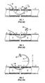
- FIGS. 1-6 designated “Prior Art,” illustrate a surgical suturing needle of the prior art.
- Needle 10 generally includes an arcuate body 12 typically having a constant radius of curvature "r.”
- a pointed tip 14 is formed on one end of arcuate body 12 and a tail portion 16 is formed on an opposite end of arcuate body 12.
- Tail portion 16 includes a suture bore 18 for receipt of an end of a length of suture material therein.
- needle 10 When used in cardiovascular, vascular and microvascular applications, needle 10 most preferably has an overall length "1" of about 0.328 to about 0.338 inches and a radius "r" on the order of about 0.1 to about 2.0 inches. While surgical needle 10 is illustrated as forming half a circle with constant radius, prior art surgical needles are also available in styles forming greater or less than half of a circular arc, for example, three eights of a circular arc.
- suturing with surgical needle 10 typically requires that surgical needle 10 be rotated almost completely about its center of radius, thus necessitating a significant amount of operating space adjacent the vascular tissue sections to be sutured.
- a distal end of first vascular tissue section A having a wall B defining a lumen C therein is approximated adjacent a distal end of a second vascular tissue section E having a wall F and defining a lumen G therein.
- Tail portion 16 of surgical needle 10 is grasped with a needle holder 36 to manipulate surgical needle 10.
- Surgical needle 10 is provided with a length of suture material 38 affixed within suture bore 18.
- Pointed tip 14 is positioned adjacent wall B and driven therethrough by rotating surgical needle 10 about its center of radius. As surgical needle 10 penetrates wall B it creates an entrance hole D in wall B. Surgical needle 10 is rotated such that it passes through lumen C and into lumen G in second vascular tissue section E.
- surgical needle 10 is rotated further to penetrate wall F thereby causing an exit hole I to be created in wall F. Pointed tip 14 is then grasped with another needle holder 36 and the tail portion 16 is released from original needle holder 36.
- surgical needle 10 is ready to be withdrawn from vascular tissue sections A and E thereby drawing a length of suture material 38 through vascular tissue sections A and E to form a stitch.
- surgical needle 10 is rotated further about its center of radius to draw a length of suture material 38 into lumen C.
- surgical needle 10 is rotated further to draw surgical needle 10 through lumens C and G, and out through exit hole I. This process draws length of suture material 38 through entrance and exit holes D and I to suture or stitch vascular tissue sections A and E together.
- surgical needle 10 requires a significant amount of space in order to be manipulated, the height of this space is indicated by height "h.”
- height "h" As can be appreciated, initial penetration of first vascular tissue section A also requires a significant amount of space.
- the suturing of vascular tissues with the prior art surgical suturing needle of the type shown as suturing needle 10 typically requires a significant amount of operating space adjacent the vascular tissue sections A and E in order to manipulate surgical needle 10.
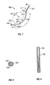
- FIG. 7 illustrates an embodiment of the surgical needle 100 of the present disclosure.
- Surgical needle 100 includes a generally arcuate portion 120 having a first end 122, a second end 124 and a radius "R."
- a pointed tip 140 is formed near first end 122 of arcuate portion 120 and a relatively straight shank 130 extends near second end 124 of arcuate portion 120.
- Arcuate portion 120 may be solid, hollow, partially hollow, channel-shaped, etc.
- Radius R is substantially larger than that used with known surgical suturing needles, such as prior art needle 10 described above, and gives a generally more flat profile to arcuate portion 120.
- Shank 130 forms a relatively abrupt juncture angle " ⁇ 1" with a tangent of second end 124 of arcuate portion 120.
- Juncture angle ⁇ 1 is in the range of about 23° to about 29°, and in a particularly useful embodiment, is approximately 26°.
- U.S. Patent No. 5,891,164 discloses a surgical needle where the juncture angle is between 30° and 70°.
- an extrapolation of a longitudinal axis 150 of shank 28 intersects arcuate portion 120 of surgical needle 100.
- This intersection may occur up to about 0.100 inches from the extrapolation line of the longitudinal axis 150 to pointed tip 140 of surgical needle 100, illustrated as "d1" in FIG. 7.
- the '164 reference discloses a surgical needle where the extrapolation line of shank does not intersect arcuate portion.
- the intersection of the present disclosure is advantageous because it may reduce the overall profile size of the surgical needle 100, particularly the juncture between the arcuate portion 120 and the shank 130, thereby allowing the juncture and shank 130 to more easily pass through the tissue and potentially reducing trauma to the tissue as the surgical needle 100 passes therethrough.
- Radius R of the present disclosure may range from about 0.151 to about 0.171 inches and may be constant or variable over its entire length.
- Arcuate portion 120 of surgical needle 100 generally has an overall length L which may range from about 0.224 to about 0.343 inches, corresponding to arch angle ⁇ 2 in the range of about 85° to about 115°.
- Shank 130 has a length which may range from about 0.078 inches to about 0.108 inches.
- Radius R, and thus arch angle ⁇ 2 may be constant or varied along the length of arcuate portion. In the embodiment where arch angle ⁇ 2 is constant, the angle may be in the range of about 85° to about 115°. In a particularly useful embodiment, the arch angle ⁇ 2 may be approximately 100°.
- the arch angle ⁇ 2 may increase from below 100° (e.g., about 85°) at the second end of the arcuate portion to above 100° (e.g., about 115°) at the first end of the arcuate portion.
- cross-section of arcuate portion 120 of surgical needle 100 may be consistent or tapered.
- Arcuate portion 120 may have a generally circular cross-section adjacent pointed tip 140 and may also have relatively flat sides 150 to increase strength and facilitate use.
- At least one portion of cross-section of arcuate portion 120 may have a diameter of about 0.010 inches. In the embodiment where arcuate portion 120 has a cross-section of relatively flat sides 150, the diameter from one side 150 to opposing side 150 may be about 0.009 inches.
- shank 130 has a generally circular cross-section and includes a bore 160 for suture attachment.
- Bore 160 is formed within shank 130 for receipt of an end of a length of suture material 170 (see FIGS. 10-14) therein.
- An end of the length of suture material 170 may be secured within bore 160 by known attaching techniques, such as, for example, crimping or use of surgical grade adhesives such as, for example, cyanoacrylate glue, epoxy cements or other medically acceptable adhesives.
- Length of bore 160 may be in the range of about 0.040 to about 0.050 inches.
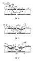
- surgical needle 100 permits vascular tissue to be sutured using significantly less operating space than surgical needles of the prior art (FIGS. 1-6).
- surgical needle 100 attached to suture material 170, may be utilized to suture together two opposed vascular tissue sections, such as, first vascular tissue section A' and second vascular tissue section E'.
- First vascular tissue section A' has an outer wall B' and defines a lumen C' therein.
- Second vascular tissue section E' has an outer wall F' and defines a lumen G' therein.
- surgical needle 100 is grasped adjacent shank 130 by first needle holder 200.
- Pointed tip 140 is positioned adjacent wall B', moves through wall B' and into inner lumen C'.
- the radius R of arcuate portion 120 and straight shank 130 allow pointed tip 140 to be inserted into wall B' without it being necessary to rotate surgical needle 20 such a large distance, as practiced in the prior art (see FIGS. 1-6).
- surgical needle 100 is passed through wall B' it creates an entrance hole D'.
- Surgical needle 100 can then be manipulated to advance arcuate portion 120 through entrance hole D' and to advance pointed tip 140 into lumen G' of second vascular tissue section E'.
- Surgical needle 100 is then manipulated to cause pointed tip 140 to penetrate wall F', creating an exit hole I'.
- shank 130 is positioned flush with or substantially parallel to an outer surface of first vascular tissue section A' (see FIG. 11).
- surgical needle 100 of the present disclosure is dimensioned and configured to be moved substantially parallel to the vascular tissue sections A' and E'. As shown in FIGS. 10-14, this motion of moving surgical needle 100 parallel to the vascular tissue sections A' and E' (as indicated by arrow X in FIGS. 11-13) requires a significantly smaller amount of operating space adjacent the vascular tissue sections A' and E'.
Abstract
Description
- The present disclosure relates generally to surgical needles and, more particularly, to a surgical needle and method particularly suited for use in limited space applications, such as cardiovascular, vascular and microvascular surgery.
- Various shapes and styles of surgical needles have been developed for use with specific suturing procedures. The needle configurations may vary according to the type of tissue to be sutured and the manner of manipulating the needle during suturing. For example, one such needle used for suturing deep fascia tissue is disclosed in
U.S. Pat. No. 5,433,728 to Kim . The needles in accordance with the '728 patent have an arcuate body with a pointed tip. The body forms an arc of approximately 180° to 230° and is joined to a relatively straight shank by a gently curving arcuate neck. - Another specific needle configuration is disclosed in
European Patent Application No. 0494644 A2 . The needles disclosed in this application are for use in abdominal surgery. One embodiment includes a straight section which bends downwardly at approximately 22° and then curves upwardly with a radius of 5/12ths of the overall length of the needle. - A further type of surgical needle configuration, referred to as a "sickle needle," is disclosed in
United States Patent No. 5,891,164 . The surgical needle disclosed in the '164 patent includes an arcuate portion and a shank portion connected thereto. There is an abrupt angle between these two portions and the angle is between 30° and 70°. This type of needle may be used when a surgeon has limited space in which to work, such as cardiovascular, vascular and microvascular surgery. - In performing cardiovascular, vascular and microvascular surgery, it is often necessary to join two hollow organ or vascular tissue sections together. This is most often accomplished by suturing opposing edges of the vascular tissue sections together. Rather than using a sickle needle, surgeons may use a needle having a substantially constant radius to suture such edges together. Most often the arc of the needle has a pointed tip at one end and a tail portion at an opposite end which is drilled to retain an end of a length of suture material therein.
- In order to suture two opposing vascular tissue sections together with prior art surgical needles of the type described above with reference to
U.S. Patent No. 5,433,728 andEuropean Patent Application No. 0494644 A2 , the suturing needle is typically held near its tail portion by a needle holder and rotated about the center of its radius through the tissue sections to be joined. For example, in order to suture two vascular tissue sections together, the two vascular tissue sections are approximated and the surgical needle having a length of suture attached thereto is rotated to cause the pointed tip to pierce through an outer wall of a first vascular tissue section and into its lumen. The needle is then further rotated to move the pointed tip of the needle through a lumen of the second vascular tissue section and out through an outer wall of the second vascular tissue section. Once the pointed tip has penetrated through the wall of the second vascular tissue section, the pointed tip is grasped with a needle holder and the tail portion is released. - In order to draw the length of suture through the two vascular tissue sections and remove the needle from the vascular tissue sections, it is necessary to continue to rotate the surgical needle further in approximately a half-circle drawing the suture material through the tissue sections. Since during the entire surgical procedure the needle must be rotated through approximately a complete circle, an operating space having a height more than half of the radius of the needle must be available adjacent the accessed vascular tissue sections.
- When a surgeon is performing cardiovascular, vascular and microvascular surgical procedures, a very limited amount of space adjacent the accessed tissue sections is available for manipulation of the surgical needle. There exists a need for a cardiovascular, vascular and microvascular surgical suturing needle configured to be manipulated within a limited space.
- The present disclosure is directed to a surgical needle that is particularly suited for use in limited space applications and a method for its use. The surgical needle generally includes an arcuate portion having a first end and a second end. A pointed tip is disposed near the first end. There is a relatively short, straight shank near a second end of the arcuate portion. The shank extends from the arcuate portion at a predetermined angle. The predetermined angle is defined by the intersection (i.e., juncture) of a tangent of the arcuate portion and the shank.
- This predetermined angle is within a range of about 23° to about 29°. In a particularly useful embodiment, the predetermined angle is approximately 26°. As discussed below, reducing the predetermined angle allows the intersection and shank to more easily pass through the tissue, thereby minimizing any potential trauma to such tissue. Furthermore, reducing its predetermined angle results in an extrapolation of a longitudinal axis of the shank to intersect the arcuate portion of the surgical needle. In a particularly useful embodiment, the distance from the extrapolation of the longitudinal axis of the shank to the pointed tip is about 0.100 inches.
- The arcuate portion has a constant or variable radius of curvature from the juncture with the shank toward the pointed tip. In the embodiment where the radius of curvature is constant, it may be in the range of about 85° to about 110°. In a particularly useful embodiment, the radius of curvature is about 100°. In the embodiment where the radius of curvature is variable, it may increase from below 100° at the second end of the arcuate portion to above 100° at the first end of the arcuate portion. It may be particularly useful for the radius of curvature to increase from about 85° at the second end of the arcuate portion to about 115° at the first end of the arcuate portion.
- The arcuate portion of surgical needle may have a cross-section that is generally circular. The arcuate portion may also be dimensioned such that opposing sides of the cross-section are substantially flat. It is also envisioned that only a portion of arcuate portion has such a cross-section. It is also envisioned that only one side of the cross-section of the arcuate section is substantially flat. Other cross-sectional configurations are also applicable and are contemplated by this disclosure.
- The shank may have a substantially circular cross-section and may have a countersunk bore disposed therein for suture attachment. A suture may be attached to the bore using any number of various known techniques, such as, for example, crimping, medical grade adhesives, etc. The length of the shank may be in the range of about 0.078 to about 0.108 inches.
- A method of using the surgical needle is also disclosed. The method includes initially grasping the shank of the surgical needle with a needle holder. The pointed tip of the surgical needle is then forced against the wall of a first tissue section and driven into the lumen. The surgical needle is then manipulated to advance the pointed tip and arcuate portion through the first lumen into a second lumen of the second vascular tissue section. The pointed tip is manipulated to penetrate the wall of the second vascular tissue section and to protrude from an outer wall thereof. The pointed tip of the surgical needle is grasped with a needle holder and the shank is released. The surgical needle is then pulled substantially parallel to an outer surface of the second vascular tissue section to thereby draw the surgical needle through the entrance hole and out the exit hole to form a stitch. It is envisioned that a plurality of stitches are made directly after the first stitch. Such a method may only require a portion of the arcuate portion to be pulled from the second lumen before the pointed tip is inserted again.
- Embodiments of the present disclosure are described hereinbelow with reference to the drawings wherein:
- FIG. 1 is a front view of a prior art surgical needle;
- FIGS. 2-6 illustrate the prior art surgical needle of FIG. 1 in various stages of being drawn through tissue;
- FIG. 7 is a front view of the surgical needle of the present disclosure;
- FIG. 8 is a cross-sectional view taken along line 8-8 of FIG. 7;
- FIG. 9 is a cross-sectional view taken along line 9-9 of FIG. 7; and
- FIGS. 10 - 14 illustrate the surgical needle of FIG. 7 in various stages of being drawn through tissue.
- FIGS. 1-6, designated "Prior Art," illustrate a surgical suturing needle of the prior art. Referring initially to FIG. 1, there is shown a prior art
surgical suturing needle 10 of the type typically used in cardiovascular, vascular and microvascular surgery.Needle 10 generally includes anarcuate body 12 typically having a constant radius of curvature "r." Apointed tip 14 is formed on one end ofarcuate body 12 and atail portion 16 is formed on an opposite end ofarcuate body 12.Tail portion 16 includes a suture bore 18 for receipt of an end of a length of suture material therein. When used in cardiovascular, vascular and microvascular applications,needle 10 most preferably has an overall length "1" of about 0.328 to about 0.338 inches and a radius "r" on the order of about 0.1 to about 2.0 inches. Whilesurgical needle 10 is illustrated as forming half a circle with constant radius, prior art surgical needles are also available in styles forming greater or less than half of a circular arc, for example, three eights of a circular arc. - Referring now to FIGS. 2-6, a brief description of the method of suturing an opposed pair of vascular tissue sections utilizing the prior art
surgical needle 10 will now be described. As noted hereinabove, suturing withsurgical needle 10 typically requires thatsurgical needle 10 be rotated almost completely about its center of radius, thus necessitating a significant amount of operating space adjacent the vascular tissue sections to be sutured. - Referring to FIG. 2, to suture two vascular tissue sections A and E together, a distal end of first vascular tissue section A having a wall B defining a lumen C therein is approximated adjacent a distal end of a second vascular tissue section E having a wall F and defining a lumen G therein.
Tail portion 16 ofsurgical needle 10 is grasped with aneedle holder 36 to manipulatesurgical needle 10. (It should be understood thatitem 36 represents a distal portion of a needle holder, and one of skill in the art can select from among the many commonly available needle holders.)Surgical needle 10 is provided with a length ofsuture material 38 affixed within suture bore 18.Pointed tip 14 is positioned adjacent wall B and driven therethrough by rotatingsurgical needle 10 about its center of radius. Assurgical needle 10 penetrates wall B it creates an entrance hole D in wallB. Surgical needle 10 is rotated such that it passes through lumen C and into lumen G in second vascular tissue section E. - Now referring to FIG. 3, once a portion of
surgical needle 10 has entered lumen G of second vascular tissue section E,surgical needle 10 is rotated further to penetrate wall F thereby causing an exit hole I to be created in wall F. Pointedtip 14 is then grasped with anotherneedle holder 36 and thetail portion 16 is released fromoriginal needle holder 36. Thus, having penetrated through both first and second vascular tissue sections A and E,surgical needle 10 is ready to be withdrawn from vascular tissue sections A and E thereby drawing a length ofsuture material 38 through vascular tissue sections A and E to form a stitch. - As shown in FIG. 4, to draw
surgical needle 10 through vascular tissue sections A and E,surgical needle 10 is rotated further about its center of radius to draw a length ofsuture material 38 into lumen C. - Referring to FIGS. 5 and 6,
surgical needle 10 is rotated further to drawsurgical needle 10 through lumens C and G, and out through exit hole I. This process draws length ofsuture material 38 through entrance and exit holes D and I to suture or stitch vascular tissue sections A and E together. With particular reference to FIG. 6, assurgical needle 10 is rotated out of vascular tissue section E,surgical needle 10 requires a significant amount of space in order to be manipulated, the height of this space is indicated by height "h." As can be appreciated, initial penetration of first vascular tissue section A also requires a significant amount of space. Thus, the suturing of vascular tissues with the prior art surgical suturing needle of the type shown as suturingneedle 10 typically requires a significant amount of operating space adjacent the vascular tissue sections A and E in order to manipulatesurgical needle 10. - FIG. 7 illustrates an embodiment of the
surgical needle 100 of the present disclosure.Surgical needle 100 includes a generallyarcuate portion 120 having afirst end 122, asecond end 124 and a radius "R." A pointedtip 140 is formed nearfirst end 122 ofarcuate portion 120 and a relativelystraight shank 130 extends nearsecond end 124 ofarcuate portion 120.Arcuate portion 120 may be solid, hollow, partially hollow, channel-shaped, etc. Radius R is substantially larger than that used with known surgical suturing needles, such asprior art needle 10 described above, and gives a generally more flat profile toarcuate portion 120.Shank 130 forms a relatively abrupt juncture angle "α1" with a tangent ofsecond end 124 ofarcuate portion 120. As used herein the term "abrupt" indicates distinct transition as opposed to gradual melding of one portion into another. Juncture angle α1 is in the range of about 23° to about 29°, and in a particularly useful embodiment, is approximately 26°. As mentioned above,U.S. Patent No. 5,891,164 discloses a surgical needle where the juncture angle is between 30° and 70°. An advantage of the present disclosure over this reference is that reducing the juncture angle allows the intersection (i.e., juncture) of thearcuate portion 120 and theshank 130, as well as theshank 130 itself, to more easily pass through the vascular tissue. - That is, as the juncture angle decreases, an extrapolation of a
longitudinal axis 150 of shank 28 intersectsarcuate portion 120 ofsurgical needle 100. This intersection may occur up to about 0.100 inches from the extrapolation line of thelongitudinal axis 150 to pointedtip 140 ofsurgical needle 100, illustrated as "d1" in FIG. 7. The '164 reference discloses a surgical needle where the extrapolation line of shank does not intersect arcuate portion. The intersection of the present disclosure is advantageous because it may reduce the overall profile size of thesurgical needle 100, particularly the juncture between thearcuate portion 120 and theshank 130, thereby allowing the juncture andshank 130 to more easily pass through the tissue and potentially reducing trauma to the tissue as thesurgical needle 100 passes therethrough. - Radius R of the present disclosure may range from about 0.151 to about 0.171 inches and may be constant or variable over its entire length.
Arcuate portion 120 ofsurgical needle 100 generally has an overall length L which may range from about 0.224 to about 0.343 inches, corresponding to arch angle α2 in the range of about 85° to about 115°.Shank 130 has a length which may range from about 0.078 inches to about 0.108 inches. Radius R, and thus arch angle α2, may be constant or varied along the length of arcuate portion. In the embodiment where arch angle α2 is constant, the angle may be in the range of about 85° to about 115°. In a particularly useful embodiment, the arch angle α2 may be approximately 100°. In the embodiment where the arch angle α2 varies, it may increase from below 100° (e.g., about 85°) at the second end of the arcuate portion to above 100° (e.g., about 115°) at the first end of the arcuate portion. - Referring to FIG. 8, cross-section of
arcuate portion 120 ofsurgical needle 100 may be consistent or tapered.Arcuate portion 120 may have a generally circular cross-section adjacentpointed tip 140 and may also have relativelyflat sides 150 to increase strength and facilitate use. At least one portion of cross-section ofarcuate portion 120 may have a diameter of about 0.010 inches. In the embodiment wherearcuate portion 120 has a cross-section of relativelyflat sides 150, the diameter from oneside 150 to opposingside 150 may be about 0.009 inches. - Now referring to FIG. 9,
shank 130 has a generally circular cross-section and includes abore 160 for suture attachment.Bore 160 is formed withinshank 130 for receipt of an end of a length of suture material 170 (see FIGS. 10-14) therein. An end of the length ofsuture material 170 may be secured withinbore 160 by known attaching techniques, such as, for example, crimping or use of surgical grade adhesives such as, for example, cyanoacrylate glue, epoxy cements or other medically acceptable adhesives. Length ofbore 160 may be in the range of about 0.040 to about 0.050 inches. - Referring now to FIGS. 10-14,
surgical needle 100 permits vascular tissue to be sutured using significantly less operating space than surgical needles of the prior art (FIGS. 1-6). Referring initially to FIG. 10,surgical needle 100, attached tosuture material 170, may be utilized to suture together two opposed vascular tissue sections, such as, first vascular tissue section A' and second vascular tissue section E'. First vascular tissue section A' has an outer wall B' and defines a lumen C' therein. Second vascular tissue section E' has an outer wall F' and defines a lumen G' therein. - Initially,
surgical needle 100 is graspedadjacent shank 130 byfirst needle holder 200.Pointed tip 140 is positioned adjacent wall B', moves through wall B' and into inner lumen C'. The radius R ofarcuate portion 120 andstraight shank 130 allow pointedtip 140 to be inserted into wall B' without it being necessary to rotate surgical needle 20 such a large distance, as practiced in the prior art (see FIGS. 1-6). Assurgical needle 100 is passed through wall B' it creates an entrance hole D'.Surgical needle 100 can then be manipulated to advancearcuate portion 120 through entrance hole D' and to advance pointedtip 140 into lumen G' of second vascular tissue section E'.Surgical needle 100 is then manipulated to cause pointedtip 140 to penetrate wall F', creating an exit hole I'. The juncture angle α1 facilitates driving pointedtip 140 through wall F' with a minimal amount of rotational motion. At this stage of insertion,shank 130 is positioned flush with or substantially parallel to an outer surface of first vascular tissue section A' (see FIG. 11). - As best seen in FIG. 11, once pointed
tip 140 has penetrated wall F' thereby creating exit hole I',shank 130 is released from the grasp offirst needle holder 200 and pointedtip 140 is grasped bysecond needle holder 210. In contrast to the rotational motion used to move prior artsurgical needle 10 through the vascular tissue sections,surgical needle 100 of the present disclosure is dimensioned and configured to be moved substantially parallel to the vascular tissue sections A' and E'. As shown in FIGS. 10-14, this motion of movingsurgical needle 100 parallel to the vascular tissue sections A' and E' (as indicated by arrow X in FIGS. 11-13) requires a significantly smaller amount of operating space adjacent the vascular tissue sections A' and E'. - Referring now to FIG. 12, as
pointed tip 140 is grasped bysecond needle holder 210 and moved substantially parallel to second vascular tissue section E' in general direction of arrow X,shank 130 is drawn through entrance hole D' in first vascular tissue section A'. This is facilitated by the juncture angle α1 which enablesshank 130 to easily slide through entrance hole D' aspointed tip 140 is pulled substantially parallel to second vascular tissue section E'. - As shown in FIG. 13, once
shank 130 has been drawn through entrance hole D', length ofsuture material 170 passes through entrance hole D'. Continued pulling ofpointed tip 140 bysecond needle holder 210 substantially parallel to second vascular tissue section E' draws length ofsuture material 170 into and through lumens C' and G'. - Continued pulling of
pointed tip 140 drawssurgical needle 100 out of lumen G', as shown in FIG. 14. The height H of the space necessary forsurgical needle 100 to be manipulated is significantly less than that of height h illustrated in FIG. 6 with respect to prior artsurgical needle 10, as discussed above. - While the above description contains many specifics, these specifics should not be construed as limitations on the scope of the present disclosure, but merely as exemplifications of various embodiments thereof. For example, it is envisioned that only one needle holder can be used to suture tissue, instead of the first and second needle holders disclosed. Those skilled in the art will envision many other possible variations that are within the scope and spirit of the present disclosure.
Claims (15)
- A surgical suturing needle comprising:an arcuate portion having a first end, a second end and a radius;a pointed tip disposed near the first end of the arcuate portion; anda shank disposed adjacent the second end of the arcuate portion, the shank being straighter than the arcuate portion and there being a juncture angle between the arcuate portion and the shank, the juncture angle being defined by a longitudinal axis of the shank and a tangent of the second end of the arcuate portion, the juncture angle being in a range of from 23° to 29°.
- The surgical suturing needle according to claim 1, wherein the juncture angle is 26° ± 2°.
- The surgical suturing needle according to claim 1 or 2, wherein the length of the shank is less than the radius of the arcuate portion.
- The surgical suturing needle according to claim 1, 2 or 3 wherein the length of the shank is between 2 and 3 mm.
- The needle of claim 4, wherein the shank length is less than 2,75 mm.
- The surgical suturing needle according to any one of the preceding claims, wherein at least a portion of the arcuate portion exhibits at least one relatively flat side.
- The surgical suturing needle according to any one of the preceding claims, wherein the shank exhibits a substantially circular cross-section.
- The surgical suturing needle according to any one of the preceding claims, wherein the shank defines a bore capable of receiving a portion of a suture material.
- The surgical suturing needle according to any one of the preceding claims, wherein an extrapolation of the longitudinal axis of the shank intersects the arcuate porion.
- Needle according to any one of the preceding claims wherein the arcuate portion substends an angle in a range of from 55° to 115°.
- The surgical suturing needle according to any one of the preceding claims, wherein the radius of the arcuate portion is constant.
- The surgical suturing needle according to any one of claims 1 to 10, wherein the radius of the arcuate portion varies from its first end to its second end.
- The surgical suturing needle according to claim 12, wherein the radius of the arcuate portion increases from its second end to its first end.
- The surgical suturing needle according to any one of the preceding claims, wherein a distance from an extrapolation of the longitudinal axis of the shank to the pointed tip is about 2,5 mm.
- A needle for use in a method of suturing a first tissue section having a wall and defining a first lumen with a second tissue section having a wall and defining a second lumen, the method including the steps of:providing a surgical needle, the surgical needle comprising an arcuate portion having a first end, a second end and a radius, a pointed tip disposed adjacent the first end of the arcuate portion, and a relatively straight shank disposed adjacent the second end of the arcuate portion, the shank and the arcuate portion forming a juncture angle therebetween, the juncture angle being in a range of about 23° to about 29° and the shank having a length;providing a needle holder;grasping the shank of the surgical needle with the needle holder;forcing the pointed tip of the surgical needle against the wall of the first tissue section and driving the pointed tip into the first lumen;advancing the pointed tip of the surgical needle through the first lumen and into the second lumen;advancing the pointed tip of the surgical needle through the wall of the second lumen;removing the needle from the shank of the surgical needle;grasping the pointed tip of the surgical needle with the needle holder; and pulling the surgical needle substantially parallel to the wall of the second lumen until at least a portion of the arcuate portion is removed from the second lumen.
Applications Claiming Priority (1)
| Application Number | Priority Date | Filing Date | Title |
|---|---|---|---|
| US11/272,555 US8292920B2 (en) | 2005-11-10 | 2005-11-10 | Sickle needle and method |
Publications (2)
| Publication Number | Publication Date |
|---|---|
| EP1785100A1 true EP1785100A1 (en) | 2007-05-16 |
| EP1785100B1 EP1785100B1 (en) | 2009-06-03 |
Family
ID=37731562
Family Applications (1)
| Application Number | Title | Priority Date | Filing Date |
|---|---|---|---|
| EP06023334A Expired - Fee Related EP1785100B1 (en) | 2005-11-10 | 2006-11-09 | Surgical sickle needle and method of using it |
Country Status (7)
| Country | Link |
|---|---|
| US (1) | US8292920B2 (en) |
| EP (1) | EP1785100B1 (en) |
| JP (1) | JP2007130457A (en) |
| AU (1) | AU2006233212B2 (en) |
| CA (1) | CA2566172A1 (en) |
| DE (1) | DE602006007079D1 (en) |
| ES (1) | ES2328056T3 (en) |
Cited By (1)
| Publication number | Priority date | Publication date | Assignee | Title |
|---|---|---|---|---|
| US10881400B2 (en) | 2016-11-18 | 2021-01-05 | Olympus Corporation | Medical stapler system |
Families Citing this family (2)
| Publication number | Priority date | Publication date | Assignee | Title |
|---|---|---|---|---|
| WO2013082671A1 (en) * | 2011-12-07 | 2013-06-13 | Research Medical Pty Ltd | Surgical trocar |
| USD938031S1 (en) * | 2019-07-14 | 2021-12-07 | Telma Micro Needles Pvt. Ltd. | Undrilled needle |
Citations (5)
| Publication number | Priority date | Publication date | Assignee | Title |
|---|---|---|---|---|
| EP0494644A2 (en) * | 1991-01-07 | 1992-07-15 | Scarfi, Andrea, Dr. med. | Surgical needle |
| US5433728A (en) * | 1994-03-02 | 1995-07-18 | Kim; Il G. | Surgical needle |
| US5725555A (en) * | 1993-10-01 | 1998-03-10 | Moll; Clemens | Atraumatic needle for surgical suturing machines |
| EP0852930A2 (en) * | 1996-12-11 | 1998-07-15 | United States Surgical Corporation | Surgical needle |
| US6723107B1 (en) * | 1999-04-19 | 2004-04-20 | Orthopaedic Biosystems Ltd. | Method and apparatus for suturing |
Family Cites Families (131)
| Publication number | Priority date | Publication date | Assignee | Title |
|---|---|---|---|---|
| US1377359A (en) * | 1920-06-24 | 1921-05-10 | Dana M Littlejohn | Surgical needle |
| US1592897A (en) * | 1925-12-02 | 1926-07-20 | Harry D Morton | Needle and method of making the same |
| US2092292A (en) * | 1936-12-23 | 1937-09-07 | Fibreboard Products Inc | Carton making machine |
| US2336689A (en) | 1941-06-17 | 1943-12-14 | Singer Mfg Co | Surgical needle |
| US2811157A (en) * | 1954-08-19 | 1957-10-29 | J A Deknatel & Son Inc | Minimal trauma surgical needle |
| US2865376A (en) | 1956-03-27 | 1958-12-23 | American Cyanamid Co | Gold plating surgical needles |
| US2865375A (en) | 1956-03-27 | 1958-12-23 | American Cyanamid Co | Plating surgical needles |
| US2841150A (en) * | 1957-05-06 | 1958-07-01 | American Cyanamid Co | Cutting edge suture needle |
| US3038475A (en) * | 1960-06-27 | 1962-06-12 | American Cyanamid Co | Surgical needles and manufacture of same |
| US3197997A (en) * | 1960-11-17 | 1965-08-03 | Leonard D Kurtz | Suture needle |
| US3265070A (en) * | 1960-11-17 | 1966-08-09 | Leonard D Kurtz | Suture needle |
| US3592196A (en) * | 1969-11-28 | 1971-07-13 | Boris Yakovlevich Daikhovsky | Surgical needle with suture retaining means |
| BE758156R (en) * | 1970-05-13 | 1971-04-28 | Ethicon Inc | ABSORBABLE SUTURE ELEMENT AND ITS |
| US3799169A (en) * | 1972-05-11 | 1974-03-26 | Ethicon Inc | Lateral release suture |
| TR17343A (en) * | 1972-05-31 | 1975-03-24 | Ethicon Inc | SUETUER THAT CAN BE RELEASED BY CONTROL |
| US3840015A (en) | 1973-06-28 | 1974-10-08 | D Gain | Photoluminescent surgical device |
| US3980177A (en) | 1973-10-26 | 1976-09-14 | Johnson & Johnson | Controlled release suture |
| US3875946A (en) * | 1974-02-27 | 1975-04-08 | Ethicon Inc | Controlled release suture |
| US3949756A (en) * | 1974-11-20 | 1976-04-13 | Ethicon, Inc. | Sutures with notch near needle-suture junction |
| US3963031A (en) | 1974-12-11 | 1976-06-15 | Ethicon, Inc. | Juncture-lubricated needle-suture combination |
| FR2300580A1 (en) | 1975-02-14 | 1976-09-10 | Ethicon Inc | NEEDLE SURGICAL ELECTRODES IMPROVEMENT |
| US4054144A (en) | 1976-05-28 | 1977-10-18 | American Cyanamid Company | Short-crimp surgical needle |
| US4034763A (en) | 1976-06-10 | 1977-07-12 | Frazier Calvin H | Ligament forming suture |
| GB1562927A (en) | 1976-06-28 | 1980-03-19 | Ethicon Inc | Bonded controlled release needle-suture combinations |
| US4128351A (en) | 1977-04-15 | 1978-12-05 | Deknatel Inc. | Sternotomy surgical needle |
| US4204542A (en) | 1977-08-03 | 1980-05-27 | Carbomedics, Inc. | Multistrand carbon coated sutures |
| US4237892A (en) | 1979-02-16 | 1980-12-09 | American Cyanamid Company | Multi-beveled, v-shaped needle point |
| US4527564A (en) | 1980-02-06 | 1985-07-09 | Janome Sewing Machine Co. Ltd. | Suturing needle for medical operation |
| US4345601A (en) | 1980-04-07 | 1982-08-24 | Mamoru Fukuda | Continuous suturing device |
| US4359053A (en) | 1980-06-05 | 1982-11-16 | Snyder Laboratories, Inc. | Means of fastening silicone tubing to a rigid surgical needle |
| US4524771A (en) * | 1982-10-28 | 1985-06-25 | Ethicon Inc. | Multiple curved surgical needle |
| US4660559A (en) | 1983-09-19 | 1987-04-28 | Ethicon, Inc. | Sterile surgical needles with a hard sharp cutting edge and method for producing the same |
| US4959068A (en) * | 1984-07-19 | 1990-09-25 | Ethicon, Inc. | Sterile surgical needle having dark non-reflective surface |
| US4777096A (en) | 1984-12-14 | 1988-10-11 | Ethicon, Inc. | Sheet containing a plurality of surgical needles |
| US4587202A (en) | 1984-12-14 | 1986-05-06 | Ethicon, Inc. | Photoetching process for making surgical needles |
| US4880002A (en) | 1985-05-30 | 1989-11-14 | Corvita Corporation | Stretchable porous sutures |
| US4890614A (en) * | 1986-02-19 | 1990-01-02 | Yasuo Nakamura | Suture needle and its manufacturing process |
| EP0232444A1 (en) | 1986-02-19 | 1987-08-19 | Yasuo Nakamura | A suture needle and its manufacturing processes |
| KR950000058B1 (en) * | 1986-06-12 | 1995-01-09 | 가부시끼가이샤 뮤텍크 | Suturing needle with suture and method of producing the same |
| US4968362A (en) | 1986-10-08 | 1990-11-06 | American Cyanamid Company | Dark metallic product |
| US4799484A (en) * | 1987-04-10 | 1989-01-24 | Ethicon, Inc. | Tapered I-beam surgical needles |
| US5437680A (en) * | 1987-05-14 | 1995-08-01 | Yoon; Inbae | Suturing method, apparatus and system for use in endoscopic procedures |
| US4935029A (en) | 1987-06-22 | 1990-06-19 | Matsutani Seisakusho Co., Ltd. | Surgical needle |
| US4799483A (en) * | 1988-02-11 | 1989-01-24 | Kraff Manus C | Suturing needle with tail mounted cutting blade and method for using same |
| JPH01317430A (en) * | 1988-06-18 | 1989-12-22 | Keisei Ika Kogyo Kk | Device for assembling surgical needle for operation |
| US4901721A (en) * | 1988-08-02 | 1990-02-20 | Hakki Samir I | Suturing device |
| US5333625A (en) * | 1988-08-18 | 1994-08-02 | Rikki Brezak | Suturing with corrosion and breakage resistant flexible wire |
| FR2643251B1 (en) * | 1989-02-20 | 1994-03-04 | Ethnor | SURGICAL SUTURE, PARTICULARLY FOR STERNOTOMY CLOSURE |
| US5041127A (en) * | 1989-02-27 | 1991-08-20 | Troutman Richard C | Offset point surgical needle |
| US4932963A (en) * | 1989-03-02 | 1990-06-12 | United States Surgical Corporation | Combined surgical needle-suture device possessing an integrated suture cut-off feature |
| US4932962A (en) * | 1989-05-16 | 1990-06-12 | Inbae Yoon | Suture devices particularly useful in endoscopic surgery and methods of suturing |
| US4981149A (en) * | 1989-05-16 | 1991-01-01 | Inbae Yoon | Method for suturing with a bioabsorbable needle |
| US5235443A (en) * | 1989-07-10 | 1993-08-10 | Hoffmann-La Roche Inc. | Polarizer device |
| US5030228A (en) * | 1989-09-15 | 1991-07-09 | Ethicon, Inc. | Surgical needle configuration with five-sided cross-section |
| US4932961A (en) * | 1989-09-15 | 1990-06-12 | Ethicon, Inc. | Surgical needle configuration with five-sided cross-section |
| US5089011A (en) * | 1989-09-27 | 1992-02-18 | United States Surgical Corporation | Combined surgical needle-suture device possessing an integrated suture cut-off feature |
| US5102418A (en) * | 1989-09-27 | 1992-04-07 | United States Surgical Corporation | Method for attaching a surgical needle to a suture |
| US5080667A (en) * | 1989-11-13 | 1992-01-14 | Ethicon, Inc. | Sterile surgical needle-suture combination |
| US5070874A (en) | 1990-01-30 | 1991-12-10 | Biocontrol Technology, Inc. | Non-invasive determination of glucose concentration in body of patients |
| US5358498A (en) | 1990-02-01 | 1994-10-25 | Deknatel Technology Corporation, Inc. | Needled suture |
| JPH03244445A (en) * | 1990-02-22 | 1991-10-31 | Matsutani Seisakusho Co Ltd | Medical suture needle |
| JPH03289951A (en) * | 1990-04-05 | 1991-12-19 | Matsutani Seisakusho Co Ltd | Edged sewing needle |
| US5059207A (en) | 1990-08-27 | 1991-10-22 | Shah Mrugesh K | Shaped needles for specialized surgical procedures |
| CA2049103C (en) * | 1990-09-06 | 1996-10-01 | Royce Lewis | Implant assist apparatus |
| US5100431A (en) * | 1990-09-27 | 1992-03-31 | Allergan, Inc. | Single stitch suture needle and method |
| US5123910A (en) * | 1990-11-07 | 1992-06-23 | Mcintosh Charles L | Blunt tip surgical needle |
| CA2704193C (en) | 1990-12-13 | 2011-06-07 | United States Surgical Corporation | Method and apparatus for tipping sutures |
| US5201760A (en) * | 1990-12-24 | 1993-04-13 | American Cyanamid Company | Surgical needle-suture combination and apparatus and method for attaching the same |
| DE4103160C2 (en) * | 1991-02-02 | 1994-09-08 | Roland Man Druckmasch | Folding apparatus with an adjustable element, in particular folding jaws or arcuate segments, having a folding mechanism cylinder |
| US5224955A (en) * | 1991-08-15 | 1993-07-06 | American Cyanamid Company | Surgical needle-suture combination and apparatus and method for attaching the same |
| US5230352A (en) * | 1992-03-04 | 1993-07-27 | American Cyanamid Company | Medical suturing device, a single-strike die mechanism, and a method of using said die mechanism for forming the medical suturing device |
| US5683415A (en) | 1992-03-13 | 1997-11-04 | Ethicon, Inc. | Surgical needle |
| US5180385A (en) * | 1992-05-21 | 1993-01-19 | Sidney Sontag | Suturing assembly and method |
| US5578044A (en) * | 1992-09-04 | 1996-11-26 | Laurus Medical Corporation | Endoscopic suture system |
| US5336239A (en) * | 1993-01-15 | 1994-08-09 | Gimpelson Richard J | Surgical needle |
| JPH06284316A (en) | 1993-03-25 | 1994-10-07 | Matsushita Electric Ind Co Ltd | Image pickup device with turntable |
| US5330441A (en) * | 1993-04-30 | 1994-07-19 | American Cyanamid Company | Surgical suturing needle and method for making same |
| US5450860A (en) * | 1993-08-31 | 1995-09-19 | W. L. Gore & Associates, Inc. | Device for tissue repair and method for employing same |
| US5411613A (en) * | 1993-10-05 | 1995-05-02 | United States Surgical Corporation | Method of making heat treated stainless steel needles |
| US5403345A (en) * | 1993-10-12 | 1995-04-04 | United States Surgical Corporation | Needle suture attachment |
| US5468251A (en) | 1993-10-12 | 1995-11-21 | Advanced Surgical, Inc. | Surgical suturing device |
| US5342397A (en) * | 1993-10-18 | 1994-08-30 | Ethicon, Inc. | Cutting edge and tapercut needles having a blunt tip |
| US5478327A (en) | 1993-10-18 | 1995-12-26 | Ethicon, Inc. | Surgical needle with decreased penetration |
| US5853423A (en) * | 1993-10-20 | 1998-12-29 | Ethicon, Inc. | Process for the manufacture of suture needles and needles produced thereby |
| AU7594794A (en) | 1993-10-22 | 1995-05-11 | Ethicon Inc. | Surgical suture needle of the taper point type |
| AU676091B2 (en) * | 1993-11-01 | 1997-02-27 | Ethicon Inc. | Process for manufacturing surgical needles |
| US5477604A (en) | 1993-11-01 | 1995-12-26 | Smith; Daniel | Process for manufacturing taper point surgical needles |
| US5549629A (en) * | 1994-03-10 | 1996-08-27 | Thomas; Stacy I. | Apparatus for covering a surgical needle to protect the user |
| US5364407A (en) | 1994-03-21 | 1994-11-15 | Poll Wayne L | Laparoscopic suturing system |
| AU2498295A (en) * | 1994-07-27 | 1996-02-08 | Ethicon Inc. | Method of manufacturing surgical needles having blunt tips |
| US5665109A (en) | 1994-12-29 | 1997-09-09 | Yoon; Inbae | Methods and apparatus for suturing tissue |
| US5667528A (en) * | 1995-11-22 | 1997-09-16 | United States Surgical Corporation | Braided suture surgical incision member attachment |
| US5716392A (en) * | 1996-01-05 | 1998-02-10 | Medtronic, Inc. | Minimally invasive medical electrical lead |
| CA2197368A1 (en) * | 1996-02-15 | 1997-08-16 | Daniel J. Smith | Radiused hollow cutting edge needle |
| US5913875A (en) * | 1996-05-30 | 1999-06-22 | Ethicon, Inc. | Taper point needle |
| US6018860A (en) * | 1996-06-07 | 2000-02-01 | Ethicon, Inc. | Process for manufacturing drilled taper point surgical needles |
| US5897572A (en) * | 1996-10-11 | 1999-04-27 | Cornell Research Foundation, Inc. | Microsurgical suture needle |
| WO1998030154A1 (en) | 1997-01-07 | 1998-07-16 | Mani, Inc. | Surgical needle, needle holder, and surgical needle device |
| US5879371A (en) * | 1997-01-09 | 1999-03-09 | Elective Vascular Interventions, Inc. | Ferruled loop surgical fasteners, instruments, and methods for minimally invasive vascular and endoscopic surgery |
| US5937504A (en) * | 1997-04-30 | 1999-08-17 | Ethicon, Inc. | Stand alone swage dial assembly |
| US5741299A (en) * | 1997-03-05 | 1998-04-21 | Rudt; Louis L. | Puncture-proof suture needle assembly |
| US5782864A (en) * | 1997-04-03 | 1998-07-21 | Mitek Surgical Products, Inc. | Knotless suture system and method |
| US5830234A (en) | 1997-04-04 | 1998-11-03 | Alto Development Corporation | Method for double wire sternotomy suture |
| US5893592A (en) * | 1997-04-08 | 1999-04-13 | Ethicon Endo-Surgery, Inc. | Partially tied surgical knot |
| US5935138A (en) * | 1997-09-24 | 1999-08-10 | Ethicon, Inc. | Spiral needle for endoscopic surgery |
| US5928268A (en) * | 1997-12-18 | 1999-07-27 | Tyco Group S.A.R.L. | Curved surgical needles and method of making the same |
| US6641593B1 (en) | 1998-06-03 | 2003-11-04 | Coalescent Surgical, Inc. | Tissue connector apparatus and methods |
| US6514265B2 (en) * | 1999-03-01 | 2003-02-04 | Coalescent Surgical, Inc. | Tissue connector apparatus with cable release |
| US6019781A (en) * | 1998-10-16 | 2000-02-01 | Worland; Richard L. | Rotator cuff needle |
| US6855159B1 (en) * | 1999-02-05 | 2005-02-15 | Eva Corporation | Surgical guide line assembly and separator assembly for use during a surgical procedure |
| US6610071B1 (en) * | 1999-07-26 | 2003-08-26 | Beth Israel Deaconess Medical Center | Suture system |
| EP1078602A3 (en) | 1999-08-26 | 2001-04-04 | Mani, Inc. | Suturing needle for medical use |
| FR2804597B1 (en) * | 2000-02-04 | 2002-04-26 | Soprane Sa | HYPER-ELASTIC NEEDLE |
| US6264675B1 (en) * | 2000-02-04 | 2001-07-24 | Gregory R. Brotz | Single suture structure |
| US6588409B2 (en) * | 2000-09-14 | 2003-07-08 | Delphi Technologies, Inc. | Engine cold start fuel control method having low volatility fuel detection and compensation |
| EP2292157B1 (en) | 2001-06-14 | 2020-06-24 | Intuitive Surgical Operations Inc. | Apparatus for surgical suturing with thread management |
| US6514030B1 (en) * | 2001-07-20 | 2003-02-04 | New Holland North America, Inc. | Ramp locks for an implement transporter |
| US7112208B2 (en) * | 2001-08-06 | 2006-09-26 | Morris John K | Compact suture punch with malleable needle |
| DE10141234A1 (en) * | 2001-08-23 | 2003-03-13 | Ethicon Gmbh | System with a surgical needle and a handle |
| US6890345B2 (en) | 2001-09-27 | 2005-05-10 | Tyco Healthcare Group Lp | Pretreatment for lubricated surgical needles |
| US6558409B1 (en) * | 2001-09-28 | 2003-05-06 | Tyco Healthcare Group Lp | Plasma treated surgical needles and methods for their manufacture |
| US7001472B2 (en) * | 2001-10-15 | 2006-02-21 | Ethicon, Inc. | Method of selectively annealing a needle |
| US7118583B2 (en) * | 2001-10-23 | 2006-10-10 | Arthrex, Inc. | Meniscal suturing instrument and method |
| US6749616B1 (en) * | 2001-11-21 | 2004-06-15 | Baylor College Of Medicine | Surgical system for repairing and grafting severed nerves and methods of repairing and grafting severed nerves |
| AU2003207698A1 (en) * | 2002-01-26 | 2003-09-02 | Emory University | Needle-suture combinations and methods of use |
| WO2004006988A2 (en) * | 2002-07-17 | 2004-01-22 | Tyco Healthcare Group Lp | Union stress needle |
| AU2003251909B2 (en) * | 2002-07-17 | 2008-11-20 | Covidien Lp | Surgical suture needle |
| JP2004113520A (en) * | 2002-09-26 | 2004-04-15 | Koseki Ika Kk | Suture material for surgery with insert-molded needle |
| US20040199185A1 (en) | 2003-02-21 | 2004-10-07 | Rose-Hulman Institute Of Technology | Suturing method and apparatus |
| US6877352B1 (en) * | 2003-07-10 | 2005-04-12 | System for securing a suture to a needle in a swaged fashion | |
| US7481826B2 (en) * | 2003-09-30 | 2009-01-27 | Ethicon, Inc. | Fluid emitting suture needle |
-
2005
- 2005-11-10 US US11/272,555 patent/US8292920B2/en not_active Expired - Fee Related
-
2006
- 2006-10-26 JP JP2006290923A patent/JP2007130457A/en active Pending
- 2006-10-27 AU AU2006233212A patent/AU2006233212B2/en not_active Ceased
- 2006-10-27 CA CA002566172A patent/CA2566172A1/en not_active Abandoned
- 2006-11-09 EP EP06023334A patent/EP1785100B1/en not_active Expired - Fee Related
- 2006-11-09 ES ES06023334T patent/ES2328056T3/en active Active
- 2006-11-09 DE DE602006007079T patent/DE602006007079D1/en active Active
Patent Citations (5)
| Publication number | Priority date | Publication date | Assignee | Title |
|---|---|---|---|---|
| EP0494644A2 (en) * | 1991-01-07 | 1992-07-15 | Scarfi, Andrea, Dr. med. | Surgical needle |
| US5725555A (en) * | 1993-10-01 | 1998-03-10 | Moll; Clemens | Atraumatic needle for surgical suturing machines |
| US5433728A (en) * | 1994-03-02 | 1995-07-18 | Kim; Il G. | Surgical needle |
| EP0852930A2 (en) * | 1996-12-11 | 1998-07-15 | United States Surgical Corporation | Surgical needle |
| US6723107B1 (en) * | 1999-04-19 | 2004-04-20 | Orthopaedic Biosystems Ltd. | Method and apparatus for suturing |
Cited By (1)
| Publication number | Priority date | Publication date | Assignee | Title |
|---|---|---|---|---|
| US10881400B2 (en) | 2016-11-18 | 2021-01-05 | Olympus Corporation | Medical stapler system |
Also Published As
| Publication number | Publication date |
|---|---|
| US20070106329A1 (en) | 2007-05-10 |
| AU2006233212A1 (en) | 2007-05-24 |
| EP1785100B1 (en) | 2009-06-03 |
| US8292920B2 (en) | 2012-10-23 |
| AU2006233212B2 (en) | 2013-03-28 |
| DE602006007079D1 (en) | 2009-07-16 |
| ES2328056T3 (en) | 2009-11-06 |
| CA2566172A1 (en) | 2007-05-10 |
| JP2007130457A (en) | 2007-05-31 |
Similar Documents
| Publication | Publication Date | Title |
|---|---|---|
| EP2265188B1 (en) | Medical suturing device | |
| US20100100125A1 (en) | Suture needle and suture assembly | |
| US6056771A (en) | Radiused tip surgical needles and surgical incision members | |
| EP0852930B1 (en) | Surgical needle | |
| US5356424A (en) | Laparoscopic suturing device | |
| US4799483A (en) | Suturing needle with tail mounted cutting blade and method for using same | |
| US5876411A (en) | Device and method for locating and sealing a blood vessel | |
| EP0687446B1 (en) | Surgical incision members for endoscopic suturing apparatus | |
| US5693071A (en) | Tapered surgical needles and surgical incision members | |
| US5709692A (en) | Surgical instrument for placing suture or fasteners | |
| US5897572A (en) | Microsurgical suture needle | |
| JP3164532B2 (en) | Suture device and method for blood vessels and the like | |
| US20100298847A1 (en) | Hydrodynamic suture passer | |
| KR20130127424A (en) | Circular bone tunneling device | |
| JP2003524480A (en) | Apparatus and method for joining and closing a hole or puncture wall in a physiological shell structure | |
| JP6737870B2 (en) | Bidirectional suturing device for medical use and its operating method | |
| EP1785100B1 (en) | Surgical sickle needle and method of using it | |
| CN115607208B (en) | Locking tangent line subassembly and locking tangent line device | |
| EP3689255B1 (en) | Recoverable percutaneous anchor | |
| CN215384260U (en) | Guide suspension wire for laparoscopic surgery | |
| EP3701881A1 (en) | Purse string suture device | |
| EP2986231B1 (en) | Delivery system | |
| US7001401B1 (en) | Device and method for holding a blood vessel | |
| JP6950905B2 (en) | Dilator | |
| CN220046013U (en) | Puncture outfit |
Legal Events
| Date | Code | Title | Description |
|---|---|---|---|
| PUAI | Public reference made under article 153(3) epc to a published international application that has entered the european phase |
Free format text: ORIGINAL CODE: 0009012 |
|
| AK | Designated contracting states |
Kind code of ref document: A1 Designated state(s): AT BE BG CH CY CZ DE DK EE ES FI FR GB GR HU IE IS IT LI LT LU LV MC NL PL PT RO SE SI SK TR |
|
| AX | Request for extension of the european patent |
Extension state: AL BA HR MK YU |
|
| 17P | Request for examination filed |
Effective date: 20070821 |
|
| 17Q | First examination report despatched |
Effective date: 20070924 |
|
| AKX | Designation fees paid |
Designated state(s): DE ES FR GB IE IT |
|
| GRAP | Despatch of communication of intention to grant a patent |
Free format text: ORIGINAL CODE: EPIDOSNIGR1 |
|
| GRAS | Grant fee paid |
Free format text: ORIGINAL CODE: EPIDOSNIGR3 |
|
| GRAA | (expected) grant |
Free format text: ORIGINAL CODE: 0009210 |
|
| AK | Designated contracting states |
Kind code of ref document: B1 Designated state(s): DE ES FR GB IE IT |
|
| REG | Reference to a national code |
Ref country code: GB Ref legal event code: FG4D |
|
| REG | Reference to a national code |
Ref country code: IE Ref legal event code: FG4D |
|
| REF | Corresponds to: |
Ref document number: 602006007079 Country of ref document: DE Date of ref document: 20090716 Kind code of ref document: P |
|
| REG | Reference to a national code |
Ref country code: ES Ref legal event code: FG2A Ref document number: 2328056 Country of ref document: ES Kind code of ref document: T3 |
|
| PLBE | No opposition filed within time limit |
Free format text: ORIGINAL CODE: 0009261 |
|
| STAA | Information on the status of an ep patent application or granted ep patent |
Free format text: STATUS: NO OPPOSITION FILED WITHIN TIME LIMIT |
|
| 26N | No opposition filed |
Effective date: 20100304 |
|
| PGFP | Annual fee paid to national office [announced via postgrant information from national office to epo] |
Ref country code: IT Payment date: 20101123 Year of fee payment: 5 |
|
| PGFP | Annual fee paid to national office [announced via postgrant information from national office to epo] |
Ref country code: ES Payment date: 20111124 Year of fee payment: 6 |
|
| PGFP | Annual fee paid to national office [announced via postgrant information from national office to epo] |
Ref country code: FR Payment date: 20121206 Year of fee payment: 7 Ref country code: DE Payment date: 20121128 Year of fee payment: 7 Ref country code: IE Payment date: 20121126 Year of fee payment: 7 |
|
| PGFP | Annual fee paid to national office [announced via postgrant information from national office to epo] |
Ref country code: GB Payment date: 20121126 Year of fee payment: 7 |
|
| PG25 | Lapsed in a contracting state [announced via postgrant information from national office to epo] |
Ref country code: IT Free format text: LAPSE BECAUSE OF NON-PAYMENT OF DUE FEES Effective date: 20121109 |
|
| REG | Reference to a national code |
Ref country code: ES Ref legal event code: FD2A Effective date: 20140527 |
|
| PG25 | Lapsed in a contracting state [announced via postgrant information from national office to epo] |
Ref country code: ES Free format text: LAPSE BECAUSE OF NON-PAYMENT OF DUE FEES Effective date: 20121110 |
|
| GBPC | Gb: european patent ceased through non-payment of renewal fee |
Effective date: 20131109 |
|
| REG | Reference to a national code |
Ref country code: DE Ref legal event code: R119 Ref document number: 602006007079 Country of ref document: DE Effective date: 20140603 |
|
| REG | Reference to a national code |
Ref country code: FR Ref legal event code: ST Effective date: 20140731 |
|
| REG | Reference to a national code |
Ref country code: IE Ref legal event code: MM4A |
|
| PG25 | Lapsed in a contracting state [announced via postgrant information from national office to epo] |
Ref country code: DE Free format text: LAPSE BECAUSE OF NON-PAYMENT OF DUE FEES Effective date: 20140603 |
|
| PG25 | Lapsed in a contracting state [announced via postgrant information from national office to epo] |
Ref country code: IE Free format text: LAPSE BECAUSE OF NON-PAYMENT OF DUE FEES Effective date: 20131109 |
|
| PG25 | Lapsed in a contracting state [announced via postgrant information from national office to epo] |
Ref country code: GB Free format text: LAPSE BECAUSE OF NON-PAYMENT OF DUE FEES Effective date: 20131109 Ref country code: FR Free format text: LAPSE BECAUSE OF NON-PAYMENT OF DUE FEES Effective date: 20131202 |