EP1780023B1 - Printing apparatus - Google Patents
Printing apparatus Download PDFInfo
- Publication number
- EP1780023B1 EP1780023B1 EP07075081A EP07075081A EP1780023B1 EP 1780023 B1 EP1780023 B1 EP 1780023B1 EP 07075081 A EP07075081 A EP 07075081A EP 07075081 A EP07075081 A EP 07075081A EP 1780023 B1 EP1780023 B1 EP 1780023B1
- Authority
- EP
- European Patent Office
- Prior art keywords
- ink
- pressure
- printhead
- reservoir
- air
- Prior art date
- Legal status (The legal status is an assumption and is not a legal conclusion. Google has not performed a legal analysis and makes no representation as to the accuracy of the status listed.)
- Expired - Lifetime
Links
Images


Classifications
-
- B—PERFORMING OPERATIONS; TRANSPORTING
- B41—PRINTING; LINING MACHINES; TYPEWRITERS; STAMPS
- B41J—TYPEWRITERS; SELECTIVE PRINTING MECHANISMS, i.e. MECHANISMS PRINTING OTHERWISE THAN FROM A FORME; CORRECTION OF TYPOGRAPHICAL ERRORS
- B41J2/00—Typewriters or selective printing mechanisms characterised by the printing or marking process for which they are designed
- B41J2/005—Typewriters or selective printing mechanisms characterised by the printing or marking process for which they are designed characterised by bringing liquid or particles selectively into contact with a printing material
- B41J2/01—Ink jet
- B41J2/135—Nozzles
- B41J2/165—Preventing or detecting of nozzle clogging, e.g. cleaning, capping or moistening for nozzles
- B41J2/16517—Cleaning of print head nozzles
- B41J2/1652—Cleaning of print head nozzles by driving a fluid through the nozzles to the outside thereof, e.g. by applying pressure to the inside or vacuum at the outside of the print head
- B41J2/16526—Cleaning of print head nozzles by driving a fluid through the nozzles to the outside thereof, e.g. by applying pressure to the inside or vacuum at the outside of the print head by applying pressure only
-
- B—PERFORMING OPERATIONS; TRANSPORTING
- B41—PRINTING; LINING MACHINES; TYPEWRITERS; STAMPS
- B41J—TYPEWRITERS; SELECTIVE PRINTING MECHANISMS, i.e. MECHANISMS PRINTING OTHERWISE THAN FROM A FORME; CORRECTION OF TYPOGRAPHICAL ERRORS
- B41J2/00—Typewriters or selective printing mechanisms characterised by the printing or marking process for which they are designed
- B41J2/005—Typewriters or selective printing mechanisms characterised by the printing or marking process for which they are designed characterised by bringing liquid or particles selectively into contact with a printing material
- B41J2/01—Ink jet
- B41J2/135—Nozzles
- B41J2/165—Preventing or detecting of nozzle clogging, e.g. cleaning, capping or moistening for nozzles
- B41J2/16517—Cleaning of print head nozzles
- B41J2/16552—Cleaning of print head nozzles using cleaning fluids
Definitions
- This invention relates to inkjet-printing apparatus, and in particular to apparatus for cleaning, maintaining and supplying ink to a printhead of an ink jet printer.
- a piezo-electric printhead (also sometime referred to as PZT printhead) of such a printer is characterised in that it has a plurality of miniature jetting chambers or "jets" closely arranged in an array.
- Each jet is arranged to project ink from a respective one of an array of orifices defined by the printhead, and the jets are selectively energised by a controller to project (or not project as the case may be) "pixels" of ink.
- the ink is projected onto a substrate to be printed, relative movement between the printhead and the substrate resulting in ink projected from one orifice being deposited along an elongate path on the substrate.
- the printhead is arranged within the printer such that the array of jets extends at a predetermined angle (for example 90°) to the direction of the relative motion between the printhead and the substrate.
- the controller selects a first combination of jets through which ink is projected, and then a second combination of jets, etc, relative movement between the substrate and the printhead resulting in a two dimensional image being printed on the substrate.
- Piezo-electric ink jet printers are used in many office and industrial applications.
- Industrial printing applications include packaging printers, which print directly onto substrates such as cardboard boxes, trays, flexible film and labels.
- Printhead arrays used in industrial applications typically range in length from 10mm to 70mm. In high resolution printheads, as many as 512 jets are arranged in a -70mm long linear array on a printhead. It will therefore be appreciated that the jets are very small. Each jet ejects a very small (picolitre order of magnitude) droplet of ink each time it is energised by the controller.
- printers Whilst such printers can produce fine resolution images, they are subject to image degradation due to one or more of the jets becoming blocked by dust or other contaminant, or otherwise fail as the result of a jet not being filled with ink to adjacent the orifice at the time the ink is to be projected (commonly referred to as a "de-primed” state), so that they no longer eject ink properly.
- This jet failure (often referred to as "jet drop out”) results in a degraded image having one or several unprinted lines running throughout the printed image in the direction of relative movement between the printhead and the substrate.
- a contaminant that does not completely block a jet can also cause problems by causing the deflection of a droplet of ink as it is ejected from the jet, such deflection resulting in a distorted image.
- the purging procedure involves forcing ink through all the jets of the printhead, with the intention of flushing out and removing any contaminants from the jets and ensuring that the jets are correctly primed, that is filled with ink to adjacent the orifices.
- the jets should be in a stable working condition (commonly referred to as a "primed" state) such that high quality printing can be commenced or recommenced.
- the purging procedure is typically initiated by the user.
- the purging action is typically brought about by putting an ink supply to the printhead under sufficient positive pressure to force some ink through all the jets of the printhead. This can be achieved by the user applying pressure manually to an ink reservoir communicating with ink in the printhead, or by applying pressure using a pump to the reservoir. Typically, positive pressure is applied for a period of a few seconds.
- the printhead In industrial applications, such as printing onto cardboard boxes or trays, the printhead is often mounted adjacent a production line, so that the boxes pass in close proximity to the printhead. In these applications the printhead is most often mounted such the jet array is vertical, or at some predetermined angle to the horizontal.
- ink When ink is purged through the jets, it collects on an orifice plate of the printhead in which the jet orifices are formed, and begins to flow down the orifice plate under gravity.
- the flow of ink is relatively slow, the ink taking a number of seconds to flow down to the bottom of the printhead.
- the longer the printhead in the vertical direction the longer the downward flow of ink takes.
- the purge procedure is generally successful in recovering jets, it can cause a number of problems. Firstly the purge procedure generally requires manual intervention and takes at least several seconds. It will be appreciated that the printhead cannot properly print images whilst it is being purged. Therefore it is therefore often necessary to stop an associated process (for example a production line) until the purge procedure has been completed. Secondly, the amount of ink consumed in the process is relatively large, often being several times greater than the amount of ink used to print an image.
- the described system has the capability of controlling the shape of a pressure pulse that is used to purge ink from the jets, that pulse having a "soft" profile (slowly rising leading edge and rapidly falling trailing edge) or a “hard” profile (rapidly rising leading edge and rapidly falling trailing edge).
- the slowly rising leading edge part of the pulse has a duration of 100 milliseconds or 200 milliseconds. It is stated that it is desirable to abruptly terminate the supply of air which causes the ink to flow out of the jets (the rapidly falling trailing edge of the pulses). This is said to cause the streaming of ink from the jets to abruptly cease. It- is stated that the described arrangement eliminates the trickling of ink from the jets.
- European Patent Specification EP 1016530 describes another arrangement for cleaning and preventing obstruction of the orifice plate of an ink jet printer.
- the device described incorporates a cleaning assembly which is moveable relative to the orifice plate to a position in which a closed chamber is formed over the orifice plate. A fluid is then pumped through the closed chamber so as to clean any contaminants from the orifice plate surface or any individual orifice in the plates.
- EP 1016530 is presented as an improvement of an earlier proposal which is described in US patent 4970535 .
- That US patent discloses an arrangement in which an ink jet orifice plate cleaner is moved into engagement with the orifice plate so as to provide a closed air passageway through which air is directed to provide the required cleaning effect.
- the described assembly is complex, requiring relative movement between a "ready to print” configuration and a “cleaning" configuration.
- air cleaning in the manner suggested in US 4970535 does not provide acceptable results.
- European patent specification EP 604029 describes another cleaning arrangement in which an air curtain is directed across an ink jet orifice plate.
- the jets are located behind an aperture in the plate, projected ink passing through that aperture before being deposited upon a substrate to be printed.
- Air flows between the apertured plate and the orifice plate and thus across the orifices.
- the airflow is maintained during printing at an airflow rate that is sufficiently slow as to not significantly effect ink projection.
- the purpose of this airflow is to avoid the build up of contaminants on the orifice plate, not to clean ink off the orifice plate.
- Cleaning of the printing head requires a separate operation, involving release of a latch mechanism to enable the orifice plate to swing away from a "ready to print" position to a position in which it can be readily cleaned.
- Positioning the orifice plate behind another plate means that none of the orifice plate is open to the space through which the substrate to be printed travels relative to the orifice plate. As a result the distance through which ink must be
- US patent 5184147 describes an inkjet printhead maintenance system incorporating various relatively moveable components including a slowly moving elongate mechanical wiper and an "air knife".
- the air knife generates a narrow stream of air which is swept across the orifice plate.
- the air knife requires relative movement between the structure generating the narrow stream of air and the orifice plate.
- the air knife is provided as only one of a number of complimentary cleaning mechanisms in an overall assembly of great complexity.
- purging In the absence of a simple fast operating jet purging system, in many applications purging generally requires the stopping of an associated process, for example a production line. As a result, users prefer to initiate the purge procedure as seldom as possible. This can result in a compromise between production line efficiently on the one hand and image quality on the other. In practice, it is common for operators to wait for printing quality to deteriorate significantly before initiating the purge procedure. It will also be appreciated that the longer dust and debris is allowed to build up on the printhead, the more purging and cleaning of the jets is likely to be necessary to fully restore print quality.
- This apparatus makes it possible to rapidly displace purged ink from the printhead using an assembly which is permanently fixed in position and which is not interposed between the printhead and a substrate onto which ink is to be projected from the printhead.
- a compact and mechanically simple printing arrangement is thus provided which can be rapidly cleaned, enabling cleaning to be performed after completion of one printing operation and before the initiation of a subsequent printing operation even if the two printing operations are spaced by only a relatively short period of time for example 1 second or less.
- Such an arrangement makes it possible to replenish a series of ink reservoirs each of which feeds a different set of jets using only one arrangement for delivering ink to all the reservoirs.
- the air curtain is directed to flow in a direction perpendicular to the elongate array of orifices.
- An ink-receiving opening may extend along the side of the array of orifices, the curtain of air being directed across the array of orifices towards the opening.
- the opening may be defined by a gap between a deflector on the side of the opening remote from the array of orifices and an edge of a surface of the printhead in which the orifices are formed.
- an edge of the deflector which defines a first side of the gap is set back relative to the surface of the printhead in which the orifices are formed such that the said deflector edge is further away from the space within which substrates to be printed are presented than the said edge of the surface of the printhead which defines a second side of the gap.
- the set back of the deflector edge may be from 0.1mm to 3mm, for example 1mm.
- the deflector preferably defines a deflector surface extending from the deflector edge which defines the first side of the gap, the deflector surface being inclined to the curtain of air so as to deflect the curtain of air towards the said space within which substrates to be printed are presented.
- the deflector surface may be inclined at an angle of from 10° to 35°, for example 20°, to the direction in which the air curtain flows across the printhead, the angle of inclination being measured between the deflector surface and a line extending from the said edge in the direction of flow.
- the deflector surface preferably extends from the said deflector edge to a downstream edge on the side of the deflector edge remote from the array of orifices, a further surface of the apparatus extending from the downstream edge of the deflector in a direction away from the said space within which substrates to be printed are presented.
- the further surface is preferably inclined to the deflector surface at an inclined angle of from 70 to 155°, e.g. 110°.
- an ink-receiving channel is defined behind the deflector, the ink-receiving channel opening into the gap and extending to a lower edge of the deflector.
- An ink collector may be located beneath a bottom end of the ink-receiving channel. The bottom end of the channel may be positioned to deliver ink to a formation on which ink will accumulate and which is in contact with or closely spaced from a surface defined by the collector.
- a manually adjustable screw may be mounted on the collector and adjustable in position relative to the formation such that ink on the formation can flow onto the screw and via the screw into the collector.
- the collector comprises an overflow, means for detecting ink flowing through the overflow, and means for signalling a fault if overflowing ink is detected.
- the detecting means preferably comprises an emitter and a detector at least one of which is positioned to be at least partially covered by overflowing ink, and means for signalling a fault if an output of the detector indicates an overflow of ink.
- the emitter and detector may be arranged to project from a support surface which is located below the printhead and which is open to the said space within which substrates to be printed are presented, the emitter and detector being connected to a sensing circuit sensitive both to the presence of overflowing ink and to the presence of an object in front of the printhead which reflects emissions from the emitter to the detector.
- the emitter and detector may be angled towards each other and angled upwards.
- the ink-receiving opening may have a width of from 0.5mm to 2mm, for example1mm.
- the air curtain may be generated from an elongate slot extending along the said one side of the array of orifices by pumping air through the slot towards the orifices.
- the slot may be defined between a body adjacent the printhead and an edge of a plate secured to the body, an air inlet communicating with a space defined between the body and the plate.
- the slot may have a width of from 0.1mm to 0.3mm, for example 0.2mm.
- Air may be delivered to the slot at a pressure of from 100,000 to 600,000 Pa (1 to 6 bar) above atmospheric pressure, for example 300,000 Pa (3 bar).
- the pressure pulse applied to the ink has a duration from initiation of the leading edge to initiation of the trailing edge of less than 1 second, e.g. less than 300ms, or less than 100ms, or within the range of 10 to 50ms.
- the pressure may be applied through a valve which is switchable between a first condition in which a source of compressed air is connected to an ink supply arrangement, and a second condition in which the ink supply arrangement is connected to an exhaust conduit which communicates with the atmosphere via an airflow restrictor.
- the airflow restrictor is manually adjustable to enable control of the slope of the trailing edge of the pressure pulse.
- the pressure pulse may be applied after a predetermined number of printing operations have been performed by projecting ink from the orifices, for example after each printing operation.
- the volume of ink delivered to the reservoir may be controlled in response to an ink demand initiated by detection of an ink level in any one reservoir section below the predetermined level, the ink supply control means being operative to deliver a predetermined volume of ink in response to an ink demand, to suspend ink delivery for a predetermined period, and to deliver further ink if an ink demand is indicated after the end of the predetermined period.
- the reservoir sections may communicate with a single compartment to which compressed air is delivered via a single air inlet to pressurise the ink in the reservoir sections, a baffle being positioned over the air inlet within the compartment to distribute incoming air evenly over all the reservoir sections.
- each reservoir section has housed within it a float which supports a magnet, displacement of the float by a changing ink level causing displacement of the magnet relative to a magnetic field sensor supported in a wall of the reservoir section, the magnetic field sensor providing an output indicating a demand for ink if the magnet assumes a predetermined position relative to the magnetic field sensor.
- the magnetic field sensor may be a Hall effect device.
- the float and magnet may be supported on an arm pivotally mounted on the reservoir section wall, or the float and magnet may be supported on an arm pivotally mounted on a lid of the reservoir.
- a printing apparatus which comprises a printhead 1 having a front surface 2 in which a linear array of orifices 3 is formed, an air supply device 4 for generating a curtain of air (represented by arrows 5) which sweeps across the surface 2, and a deflector plate 6 located downstream of the surface 2.
- the surface 2 faces a path along which substrates to be printed (not shown) are transported. Ink is projected from the orifices 3 onto such substrates.
- the printhead 1 may be of any conventional type.
- the front surface 2 of such printheads which defines the orifices 3 is generally referred to as an "orifice plate" and that term will be used hereinafter for the surface 2 in which the orifices 3 are formed.
- the orifice plate 2 is planar and extends vertically, although it will be appreciated that in other embodiments of the invention the orifice plate 2 need not be planar and may be mounted so as to be inclined to the vertical, at any angle between 0° and 90°.
- the air supply device 4 is supplied with compressed air via a conduit 7, the supply of air being controlled by a solenoid-actuated valve 8.
- the air curtain 5 is established so as to sweep any ink or contaminants on the orifice plate 2 towards a gap 9 defined between a downstream edge 10 of the orifice plate and an upstream edge 11 of the deflector plate 6.
- Ink swept from the orifice plate 2 is directed by the flow of air into the gap 9 and thereafter flows downwards under gravity to drip from a drip point 12 on the lower edge of the deflector plate 6.
- Such ink is collected in a collector 13.
- the air supply device 4 has a rearwardly extending (relative to the orifice plate 2) portion which is coupled to the air supply conduit 7 and an open ended portion arranged so as to direct the curtain of air 5 in a plane indicated by line A which is parallel to the orifice plate 2.
- the open end of the air supply device 4 defines an elongate outlet of substantially rectangular cross section. The outlet may be for example 0.2mm wide.
- the upstream edge 11 of the deflector plate 6 is set back from the orifice plate surface 2, the edge 11 lying on a plane indicated by line B in Figure 2 , the plane indicated by line B being parallel to the plane indicated by line A.
- the spacing between plane B and the plane including the orifice plate surface 2 is less than 1mm.
- the width of the gap 9 (that is the spacing between the edge 11 of the deflector plate 6 and a line through the edge 10 of the orifice plate 2 extending perpendicular to the line B) is between 0.5mm and 1.5mm, for example 1mm.
- the deflector plate 6 extends in a direction parallel to a plane indicated by line C, the plane C being inclined to the plane of the orifice plate 2 by an angle ⁇ which in the illustrated embodiment is approximately 20° but will generally be in the range of 10° to 35°.
- the deflector plate 6 has a width (the dimension in the direction away from the printhead parallel to the line C) of approximately 5mm.
- the downstream edge of the plate 6 is cut back to define the angle ⁇ shown in Figure 2 . That angle (which is equal to the included angle defined between the surfaces extending from the downstream edge of the plate 6) will typically be of the order 110° but will generally be in the range of 70° to 155°.
- the downstream edge of the plate 6 is cut back in order to improve the flow of air over the orifice plate 2.
- the presence of the box increases air flow resistance. If the downstream edge of the plate 6 was not cut back such that an extensive surface was defined extending parallel to the plane A (corresponding to the sum of the angles ⁇ and ⁇ being equal to 180°), a small elongate gap would be defined between the printhead assembly and the box downstream of the plate 6. Such a gap would result in air flow resistance that could disrupt the flow of the air curtain across the orifice plate 2.
- FIG. 3 illustrates the interconnection of the printhead 1, the air supply device 4 and the waste ink collector 13 to associated components.
- Ink is supplied to the printhead 1 from a reservoir 14.
- the reservoir 14 comprises a first inlet 15 connected via one-way check valves 16 and 17 (to ensure unidirectional flow of ink) to a conduit 18 leading from a main ink supply storage vessel (not shown) and to a conduit 19 which is coupled by an ink recycling mechanism to the collector 13.
- the reservoir 14 also has a second inlet 20 connected via a valve 21 to a compressed air supply conduit 22 and an air exhaust conduit 23 terminating in a restrictor valve 24 which may be manually adjusted to vary the rate at which air can be exhausted through the conduit 23.
- the valve is controllable to assume either an "open" condition in which conduits 20 and 22 are in communication, or a "closed” condition in which conduits 20 and 23 are in communication.
- the conduit 19 is coupled to the ink collector 13 by a conduit 25 leading to a pump 26, a conduit 27 into which the pump 26 delivers ink from the collector 13, and a filtering unit 28 which ensures that only ink which is sufficiently clean for re-use is deliver to the reservoir 14.
- the pressure of air supplied to the air supply device 4 will typically be of the order of 3 bar (300,000 Pa).
- the valve 8 will either be closed or fully open so as to deliver the supply pressure to the interior of the air supply device 4.
- the compressed air delivered to the valve 8 will be appropriately regulated to maintain the desired pressure and the supplied air will be appropriately cleaned and filtered.
- the same supply of air is used to deliver compressed air to conduit 22 connected to valve 21, but the pressure applied to the surface of the ink in the reservoir 14 may be limited as described with reference to Figures 4 and 5 . In that in the described embodiment the pressure is limited to 1 bar above atmospheric pressure, but will be limited to a range of from 0.2 to 0.8 bar or 0.4 to 0.6 bar for example.
- valves 8 and 21 and the pump 26 are controlled by a controller 29.
- a controller 29 When a substrate is to be printed the valve 8 is closed and the valve 21 is closed. Thus no air flows across the orifice plate 2 and there is therefore no risk of projected jets of ink being deflected from their intended path.
- a purge procedure is executed in which initially the valve 8 is opened so as to establish a flow of air across the orifice plate 2, and then the valve 21 is opened to apply a positive pressure to the ink within the reservoir 14, causing ink to be discharged out of the orifices 3 onto the surface of the orifice plate 2.
- the printer is then ready for the next printing cycle. It may take some time for ink to run down into the collector 13 but as it is retained in the gap 9 on the downstream side of the orifice plate 2 this does not impede the normal operation of the printer.
- the pump 26 is used to periodically transfer ink from the collector 13 to the reservoir 14. For example, the pump 26 may be turned on for a predetermined period after each purge procedure.
- the time which elapses between initiation of a purge procedure and delivery of substantially all of the purged ink to the gap 9 is the sum of the duration of the period within which ink is purged from the orifices in the orifice plate 2 and the period of time taken for the purged ink to be swept into the gap 9.
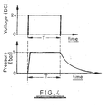
- Minimisation of the period for which positive pressure is applied to ink in the reservoir is therefore desirable and accordingly as illustrated in Figures 4 and 4A in the described embodiment of the invention a short duration pulse of positive pressure is applied to the ink in the reservoir 14.
- Figure 4 represents an idealised performance which could be achieved using extremely fast-acting components, whereas Figure 4A represents the performance achieved with readily available standard components.
- the upper half of Figure 4 shows a voltage versus time diagram representing a control voltage applied to the valve 21, a zero voltage corresponding to closure of the valve 21 and 24 volts corresponding to full opening of the valve 21.
- a control voltage pulse of duration T having a steeply rising leading edge and a steeply falling trailing edge is applied to the valve 21.
- the valve 21 is arranged however when "closed" to connect the exhaust conduit 23 to the reservoir inlet 20. As a result when the valve 21 is closed air can bleed out of the reservoir 14 at a rate determined by the setting of the restrictor valve 24.
- the lower half of Figure 4 shows the variation of the positive pressure applied to the reservoir 14 with time. It will be seen that the pressure rises rapidly as soon as the valve 21 is opened but falls relatively slowly when the valve 21 is closed, the rate of fall being determined by the setting of the restrictor valve 24.
- the pressure pulse applied to ink within the reservoir 14 has a relatively rapidly rising leading edge and a relatively slowly falling trailing edge. It is desirable for the leading edge to be relatively rapidly rising as this serves to minimise the duration of the purge cycle.
- the resultant sudden removal of the force causing ink to be purged out of the orifices can cause individual jets to be de-primed or can cause air to be sucked into the printhead which could disrupt printhead operation.
- a jet will be de-primed if it is not full of ink with the ink forming a meniscus at the jet orifice.
- the period T will not be more than 1 second and much shorter periods of time can be used with success.
- T will be less than 100ms and good results have been achieved with pressure pulses generated using a voltage pulse of duration T between 10ms and 30ms.
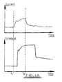
- Figure 4 illustrates the performance achieved in one practical embodiment of the invention in which the valve 21 was obtained from MAC Valve Europe, part number 34AA BA GD FA - 1BA with a specified on time of 3.4ms (time taken to respond to a valve open control input) and an off time of 15ms (time taken to respond to a valve close control input).
- the restrictor 24 was obtained from SMC UK, part number AS1001F-04 and had a simple manually adjustable screw arrangement.
- the upper part of Figure 4A represents current drawn by the valve, and the lower part represents the pressure in the inlet 20.
- valve 21 begins to close, there is an initial rapid fall in the pressure within inlet 20, but thereafter there is a relatively slow fall off in the pressure within inlet 20 as air flows out through the restrictor 24.
- the initial rapid fall in pressure reduces the period for which ink is being purged, whereas the subsequent slow fall in pressure avoids problems with jet de-priming.
- the control input to the valve 21 has a duration (t 2 -t 1 ) of 20ms.
- the resultant pressure pulse has a duration of about 30ms until the initial rapid fall in pressure, the pressure then falling further over a period of several tens of milliseconds.
- a pressure pulse duration of 30ms has produced good results, but acceptable results have been achieved with the particular printhead used using pressure pulse durations in the range 10 to 50ms and larger pressure pulses will be appropriate with different printheads and associated equipment.
- ink may continue to be purged from the printhead orifices for a substantial period dependent upon the hydrodynamic characteristics of the overall assembly. For example, ink may still be purged more than 100ms after termination of the pressure pulse.
- the air curtain which cleans the orifice plate should be maintained for a sufficient duration to ensure that all purged ink has been displaced off the orifice plate, for example for a duration of 200ms or 300ms. The more efficient the cleaning the better, as the risk of dust sticking to the orifice plate is reduced. In a very dirty environment, a decision might be taken to maintain the air curtain except during printing, although there will be a trade-off between cleaning efficiency and the cost of compressed air supplying the air curtain.
- Figures 5 and 6 show in greater detail one possible arrangement of the collector 13 which collects ink dripping from the drip point 12 at the bottom of the deflector plate 6.
- Figure 5 is a schematic perspective view from in front of the collector 13
- Figure 6 is a view from above showing that the collector 13 has a first front wall portion 30 extending parallel to the orifice plate surface 2 and a second front wall portion 31 extending parallel to the outer face of the deflector plate 6.
- the collector 13 extends beyond the edges of the printhead and the deflector plate such that the horizontal spacing between the top edge of the front wall portion 30 and the orifice plate 2 is in the range of 0.5 to 2.5mm and preferably is approximately 1mm.
- the same spacing is maintained between the upper edge of the second front wall portion 31 and the plane of the front surface of the deflector plate 6.
- the upper edge of the front wall portion 31 is contoured so as to follow the lower edge of the drip point 12 as shown in Figure 12 .
- the upper edge of the first and second front wall portions 30 and 31 is in close proximity to the drip point 12 and the lower edge of the orifice plate 2. This facilitates the rapid transfer of ink by capillary action into the collector 13.
- the collector 13 is shaped so as to cause collected ink to run backwards away from the front wall portions 30 and 31 and into a cup-shaped sump from where it is sucked away by the pump 26 ( Figure 3 ). Ink may be recycled by pumping it through the filtering unit 28 directly into the reservoir which is close-coupled to the printhead as shown in Figure 3 , or alternatively to a main supply vessel which may be positioned at a relatively remote location and from which ink is delivered to the reservoir 14 so as to maintain the ink level within the reservoir 14 within acceptable limits.
- the collector 13 may be modified to support components which enable detection of a problem resulting in overflow of the collector 13 and detection of products moving in close proximity to the orifice plate 2.
- an emitter 32 and a detector 33 are mounted so as to protrude from the first front wall portion 30 of the collector 13, that is the portion immediately below the orifice plate 2.
- the emitter and detector are mounted so as to protrude by a small distance, for example 2mm, from the wall 30.
- the emitter 32 and detector 33 are mounted at an angle ⁇ (typically approximately 70°) to the plane of the front portion 30 of the collector 13 so as to be angled slightly towards one another.
- the emitter and detector are also mounted as an angle ⁇ of approximately 5° to the horizontal.
- substrates to be printed e.g. boxes
- the emitter 32 and detector 33 are connected to the controller 29 of Figure 3 .
- Signals received by the detector 33 include a component that represents an amount of light emitted by the emitter 32 and transmitted directly to the detector 33. Such direct communication between an emitter and detector is generally referred to as "cross talk".
- the signal received by the detector may also include a further component which represents light that has been emitted by the emitter 32 and reflected back to the detector from an object placed in front of the emitter/detector pair.
- This second component of the detected signal may be processed by the controller 29 to provide a signal representing the presence of an object in front of the printhead which in normal circumstances will be an object defining a surface on which information is to be printed.
- the arrangement may be set up to limit the range of distances away from the sensors that a "product" can be sensed. In some printing processes it is advantageous to ignore products that are beyond a certain maximum acceptable distance away from the printhead.
- the emitter/detector pair as shown in Figures 7 to 10 can be used to detect the presence of a box or the like on which a pattern is to be printed.
- the emitter/detector pair can be used to detect overflow of collected ink.
- an overflow outlet 34 is defined in the front wall portion 30 immediately above the detector 33.
- ink levels within the collector 13 will be such that ink cannot flow through the overflow outlet 34.
- Such circumstances are represented in Figure 9 . If however as a result of failure collected ink is not discharged from the collector 13 via the conduit 25, the ink level will rise such that ink will flow through the outlet 34 onto the detector 33.
- the reservoir 14 from which ink is delivered to the printhead 1 is shown as a single vessel.
- the vertical extent of the array of orifices 3 in the orifice plate 2 is limited to for example 10mm. If a greater vertical extent of the array of orifices is required, and arrays having a vertical height of 70mm are well known, it is desirable to divide the orifice plate into vertically spaced sections with each section being supplied from a separate reservoir section, the reservoir section being positioned at different heights such that the relative virtual positions of each reservoir section/orifice plate section pair are substantially the same.
- the orifice plate receives ink from multiple ink supply conduits, each conduit sucking one reservoir section to a respective one orifice plate section.
- This avoids hydrostatic pressure presenting too great a pressure difference as between orifices at the top of the array and orifices at the bottom of the array.
- Such hydrostatic pressures can result either in the uppermost orifices not being correctly primed or ink being discharged unintentionally from orifices adjacent the bottom of the array.
- Figure 11 illustrates a reservoir 14 divided into four vertically spaced sections with each section feeding a respective group of orifices.
- the schematically illustrated reservoir 14 comprises an uppermost reservoir section 35, a lowermost reservoir section 36, an upper intermediate reservoir section 37 and a lower intermediate reservoir section 38.
- Ink can be delivered to the uppermost section 35 from the first reservoir inlet 15 (see Figure 3 ).
- the uppermost reservoir section 35 has an overflow such that if that section is overfilled ink will overflow into the upper intermediate section 37.
- section 37 overflows into section 38 and section 38 overflows into section 36.
- the lowermost section 36 will never overflow.
- Each of the sections is connected to a respective outlet 39 which in turn is connected to a respective group of the jets of the associated printhead.
- each reservoir section relative to the respective group of orifices is substantially the same so that the same pressure differentials will apply in the case of each of the four groups of orifices making up the single array of orifices in the printhead.
- the interior of a compartment in which each of the reservoir sections 36 to 38 is housed will be held at normal atmospheric pressure.
- pressure will be increased by approximately 1 bar as a result of compressed air being pumped into the reservoir via inlet 20.
- a baffle plate 40 is arranged over the inlet 20 so as to distribute incoming compressed air evenly across all of the reservoir sections.
- Each reservoir section is provided with a sensor arrangement schematically represented in Figure 11 by circles 41.
- Each sensor provides an output to the controller 29 ( Figure 3 ) representative of the level of ink within the respective reservoir section. If any one sensor indicates that the ink level within the respective reservoir section has fallen below a predetermined lower limit, ink is pumped into the reservoir so as to be delivered initially into the uppermost reservoir section 41. If it is that section which has been indicated as empty, ink is supplied until the level sensor of that section indicates that the level has risen to a predetermined upper limit. In such circumstances ink does not overflow from the upper reservoir section 35.
- ink is still delivered to the uppermost section 35 but cascades down the series of reservoir sections until it reaches the reservoir which requires refilling. As soon as that reservoir has been refilled to a predetermined level the delivery of ink to the uppermost section is terminated.
- ink can be delivered to the uppermost section 35 in a controlled manner. For example, whenever a demand for ink is signalled by one of the sensors 41, a controlled volume of ink could be delivered, the volume being limited to ensure that overflow cannot occur.
- Figure 12 is a schematic illustration of an ink level sensor which could be used to sense the level of ink in each of the reservoir sections 35 to 38.
- a Hall effect magnetic sensor 42 is mounted on the outside surface of a wall 43 of the ink reservoir.
- Mounted within the reservoir is a float 44, the float 44 being supported on a lower arm 45 that is pivotally supported on an upper arm 46 secured to the inner wall of the reservoir.
- the pivotal lower arm 45 supports a magnet 47.
- the ink level when the reservoir is substantially empty is indicated by line 48. If the ink level rises the float moves up with the ink, causing the magnet 47 to swing away from the wall 43 and hence to move away from the Hall effect detector 42.
- the Hall effect detector 42 can be connected to a sensing circuit which signals that the reservoir is substantially empty as soon as the magnet 47 moves into close proximity to the wall 43. Thus the output of the Hall effect sensor 42 can be used to control the supply of ink to the reservoir.
- a float 49 is mounted on an arm 50 which is mounted to pivot about a pivot axis 51, the pivot axis being supported on a member 52 which forms part of the lid of the reservoir.
- a Hall effect sensor 53 is mounted on the lid member 52.
- the arm 50 supports a bipolar magnet 54 arranged such that rotation of the arm 50 about the pivot 51 substantially alters the magnetic field to which the Hall effect sensor 53 is exposed.
- an output from the Hall effect sensor 53 can be used to control the delivery of ink to the reservoir in which the float 49 is positioned, the orientation of the float 49 in Figure 13 corresponding to a reservoir empty condition.
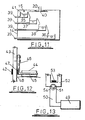
- a single piece cast and machined body 55 defines a deflector plate 56 corresponding to the deflector plate 6 of Figures 1 to 3 and an air inlet 57 which in use is connected to an air supply conduit corresponding to the air supply conduit 7 of Figures 1 to 3 .
- a printhead body 58 is mounted on the body 55, the printhead body defining an orifice plate 59 corresponding to the orifice plate 2 of Figures 1 to 3 .
- a linear array of orifices extends down the centre of the orifice plate 59 at the position indicated by numeral 60.
- a plate 61 is secured by screws 62 to the body 55, the plate 61 defining with the body a channel 63 which communicates with the air inlet 57 and from which a curtain of air is directed across the orifice plate 59 when the air inlet 57 is connected to a supply of compressed air.
- the surface facing substrates to be printed upon is cut back on the downstream side of the deflector plate. Whereas in Figure 2 , the cutback is from a sharp edge on the downstream side of the plate 6, in Figure 14 the cutback is from a short surface extending parallel to the orifice plate 59 from the downstream edge of the deflector plate 56.
- a substantial volume of ink can be retained within the channel 66 so that, even if a relatively large volume of ink is purged onto the orifice plate 59, all of that volume can be deflected into and retained within the channel 66 pending the downward flow of the retained ink into the ink collector at the foot of the deflector plate 56.
- the gap between the edges 64 and 65 is 1mm, and the channel 66 into which that gap opens has a rectangular cross-section with a length of 4mm and a width of 1mm.
- Ink flowing down the channel 66 flows onto a projection 67 arranged over a cavity formed in the base of the assembly which forms an ink collection vessel.
- a grub screw is positioned within that vessel which can be manually adjusted so as to just touch the projection 67 onto which ink flows, thereby facilitating the flow of ink into the collector and minimising the risk of a large drop of ink forming at the base of the channel 66 and thereby minimising the risk of the channel 66 becoming filled with ink so that some ink could emerge in the forwards direction from the channel 66.
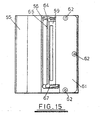
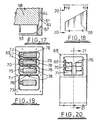
- the assembly comprises a machined casting 68 divided by three partitions 69, 70 and 71 into an uppermost section 72, a lowermost section 73, an upper intermediate section 74 and a lower intermediate section 75.
- a slot 76 is formed in each of the partitions 69, 70 and 71, each slot defining a lower edge 77 over which ink can overflow from one reservoir to the immediately adjacent lower reservoir.
- a respective ink outflow passageway 78 communicates with the base of each of the reservoir sections.
- Each reservoir section receives a level sensing assembly including a float 79.
- the level sensing assemblies can be of the type described with reference to Figure 12 , each float controlling the position of a magnet the position of which is in turn sensed by a Hall effect sensor (not shown) mounted in a recess on an outer surface of the casing 68.
- the casing 68 shown in Figures 18 to 21 is in use closed by a top plate (not shown) having a central air inlet aperture, a baffle plate being located immediately beneath the closure plate so as to distribute incoming air evenly over all of the four reservoir sections. This avoids the possibility of a sudden inrush of air displacing ink from a reservoir section located beneath the air inlet.
Abstract
Description
- This invention relates to inkjet-printing apparatus, and in particular to apparatus for cleaning, maintaining and supplying ink to a printhead of an ink jet printer.
- Types of printers exist which make use of so called piezo-electric ink-jet printing technology. A piezo-electric printhead (also sometime referred to as PZT printhead) of such a printer is characterised in that it has a plurality of miniature jetting chambers or "jets" closely arranged in an array. Each jet is arranged to project ink from a respective one of an array of orifices defined by the printhead, and the jets are selectively energised by a controller to project (or not project as the case may be) "pixels" of ink. The ink is projected onto a substrate to be printed, relative movement between the printhead and the substrate resulting in ink projected from one orifice being deposited along an elongate path on the substrate. The printhead is arranged within the printer such that the array of jets extends at a predetermined angle (for example 90°) to the direction of the relative motion between the printhead and the substrate. The controller selects a first combination of jets through which ink is projected, and then a second combination of jets, etc, relative movement between the substrate and the printhead resulting in a two dimensional image being printed on the substrate.
- Piezo-electric ink jet printers are used in many office and industrial applications. Industrial printing applications include packaging printers, which print directly onto substrates such as cardboard boxes, trays, flexible film and labels.
- Current industrial printers use a range of different inks in conjunction with a variety of different models of piezo-electric printheads. Some utilise liquid ink, others utilise solid ink which is heated so as to phase-change to liquid within the printer, the ink being liquid at the time it is ejected from the jets.
- Printhead arrays used in industrial applications typically range in length from 10mm to 70mm. In high resolution printheads, as many as 512 jets are arranged in a -70mm long linear array on a printhead. It will therefore be appreciated that the jets are very small. Each jet ejects a very small (picolitre order of magnitude) droplet of ink each time it is energised by the controller.
- Whilst such printers can produce fine resolution images, they are subject to image degradation due to one or more of the jets becoming blocked by dust or other contaminant, or otherwise fail as the result of a jet not being filled with ink to adjacent the orifice at the time the ink is to be projected (commonly referred to as a "de-primed" state), so that they no longer eject ink properly. This jet failure (often referred to as "jet drop out") results in a degraded image having one or several unprinted lines running throughout the printed image in the direction of relative movement between the printhead and the substrate. A contaminant that does not completely block a jet can also cause problems by causing the deflection of a droplet of ink as it is ejected from the jet, such deflection resulting in a distorted image.
- In certain industrial applications such as printing onto cardboard boxes or trays, a significant contributor of contamination is dust, either airborne or resting on the surface of the cardboard. The piezo-electric printing process requires the printhead jet array face to come into very close proximity with the target substrate. Furthermore there can be a build up of static electricity in the production process in the area around the printer, which can result in dust being positively attracted to the print face. Thus particularly in industrial applications contamination of jets is a major problem.
- Given the problems referred to above, it is common practice, particularly in industrial applications, to follow a procedure often referred to as "purging" in order to maintain or restore the proper function of the jets in the printhead. The purging procedure involves forcing ink through all the jets of the printhead, with the intention of flushing out and removing any contaminants from the jets and ensuring that the jets are correctly primed, that is filled with ink to adjacent the orifices. After performance of the purging procedure, the jets should be in a stable working condition (commonly referred to as a "primed" state) such that high quality printing can be commenced or recommenced.
- In known industrial printers, the purging procedure is typically initiated by the user. The purging action is typically brought about by putting an ink supply to the printhead under sufficient positive pressure to force some ink through all the jets of the printhead. This can be achieved by the user applying pressure manually to an ink reservoir communicating with ink in the printhead, or by applying pressure using a pump to the reservoir. Typically, positive pressure is applied for a period of a few seconds.
- In industrial applications, such as printing onto cardboard boxes or trays, the printhead is often mounted adjacent a production line, so that the boxes pass in close proximity to the printhead. In these applications the printhead is most often mounted such the jet array is vertical, or at some predetermined angle to the horizontal. When ink is purged through the jets, it collects on an orifice plate of the printhead in which the jet orifices are formed, and begins to flow down the orifice plate under gravity. The flow of ink is relatively slow, the ink taking a number of seconds to flow down to the bottom of the printhead. Of course, the longer the printhead in the vertical direction, the longer the downward flow of ink takes.
- Since a relatively large volume of ink (as compared with the volume of ink normally projected by an individual jet) is purged out of the orifices, the jets are not able to jet ink properly to create an image until substantially all the ink has flowed down away from the jets or has otherwise been moved away from the jets. Generally steps are taken to remove purged ink. For example, purged ink is soaked into a cloth which is then disposed off. This can easily result in ink being dripped onto the floor or surrounding factory equipment, creating unwanted mess, which is difficult to remove and clean. The wasted purged ink is a considerable percentage of the total ink consumption. Furthermore, wiping away purged ink in this way typically takes several seconds. The total time taken to complete a single ink purge procedure is thus substantial.
- Accordingly, although the purge procedure is generally successful in recovering jets, it can cause a number of problems. Firstly the purge procedure generally requires manual intervention and takes at least several seconds. It will be appreciated that the printhead cannot properly print images whilst it is being purged. Therefore it is therefore often necessary to stop an associated process (for example a production line) until the purge procedure has been completed. Secondly, the amount of ink consumed in the process is relatively large, often being several times greater than the amount of ink used to print an image.
- Various proposals for improving ink purge procedures have been proposed. For example, one known purging procedure described in
British Patent GB 2339170 -
International patent specification WO 89/04255 -
European Patent Specification EP 1016530 describes another arrangement for cleaning and preventing obstruction of the orifice plate of an ink jet printer. The device described incorporates a cleaning assembly which is moveable relative to the orifice plate to a position in which a closed chamber is formed over the orifice plate. A fluid is then pumped through the closed chamber so as to clean any contaminants from the orifice plate surface or any individual orifice in the plates. - The highly complex arrangement of
EP 1016530 is presented as an improvement of an earlier proposal which is described inUS patent 4970535 . That US patent discloses an arrangement in which an ink jet orifice plate cleaner is moved into engagement with the orifice plate so as to provide a closed air passageway through which air is directed to provide the required cleaning effect. Once again the described assembly is complex, requiring relative movement between a "ready to print" configuration and a "cleaning" configuration. Furthermore it is stated inEP 1016530 that air cleaning in the manner suggested inUS 4970535 does not provide acceptable results. - European patent specification
EP 604029 -
US patent 5184147 describes an inkjet printhead maintenance system incorporating various relatively moveable components including a slowly moving elongate mechanical wiper and an "air knife". The air knife generates a narrow stream of air which is swept across the orifice plate. Thus the air knife requires relative movement between the structure generating the narrow stream of air and the orifice plate. Furthermore, the air knife is provided as only one of a number of complimentary cleaning mechanisms in an overall assembly of great complexity. - In the absence of a simple fast operating jet purging system, in many applications purging generally requires the stopping of an associated process, for example a production line. As a result, users prefer to initiate the purge procedure as seldom as possible. This can result in a compromise between production line efficiently on the one hand and image quality on the other. In practice, it is common for operators to wait for printing quality to deteriorate significantly before initiating the purge procedure. It will also be appreciated that the longer dust and debris is allowed to build up on the printhead, the more purging and cleaning of the jets is likely to be necessary to fully restore print quality.
- It is an object of the present invention to provide an improved ink jet printing apparatus which addresses one or more of the problems outlined above.
- This object is solved by the features of
claim 1. - This apparatus makes it possible to rapidly displace purged ink from the printhead using an assembly which is permanently fixed in position and which is not interposed between the printhead and a substrate onto which ink is to be projected from the printhead. A compact and mechanically simple printing arrangement is thus provided which can be rapidly cleaned, enabling cleaning to be performed after completion of one printing operation and before the initiation of a subsequent printing operation even if the two printing operations are spaced by only a relatively short period of time for example 1 second or less.
- Preferred embodiments are defined in the dependent claims.
- Such an arrangement makes it possible to replenish a series of ink reservoirs each of which feeds a different set of jets using only one arrangement for delivering ink to all the reservoirs.
- Preferably, the air curtain is directed to flow in a direction perpendicular to the elongate array of orifices. An ink-receiving opening may extend along the side of the array of orifices, the curtain of air being directed across the array of orifices towards the opening. The opening may be defined by a gap between a deflector on the side of the opening remote from the array of orifices and an edge of a surface of the printhead in which the orifices are formed.
- Preferably, an edge of the deflector which defines a first side of the gap is set back relative to the surface of the printhead in which the orifices are formed such that the said deflector edge is further away from the space within which substrates to be printed are presented than the said edge of the surface of the printhead which defines a second side of the gap. The set back of the deflector edge may be from 0.1mm to 3mm, for example 1mm.
- The deflector preferably defines a deflector surface extending from the deflector edge which defines the first side of the gap, the deflector surface being inclined to the curtain of air so as to deflect the curtain of air towards the said space within which substrates to be printed are presented. The deflector surface may be inclined at an angle of from 10° to 35°, for example 20°, to the direction in which the air curtain flows across the printhead, the angle of inclination being measured between the deflector surface and a line extending from the said edge in the direction of flow. The deflector surface preferably extends from the said deflector edge to a downstream edge on the side of the deflector edge remote from the array of orifices, a further surface of the apparatus extending from the downstream edge of the deflector in a direction away from the said space within which substrates to be printed are presented. The further surface is preferably inclined to the deflector surface at an inclined angle of from 70 to 155°, e.g. 110°.
- Preferably an ink-receiving channel is defined behind the deflector, the ink-receiving channel opening into the gap and extending to a lower edge of the deflector. An ink collector may be located beneath a bottom end of the ink-receiving channel. The bottom end of the channel may be positioned to deliver ink to a formation on which ink will accumulate and which is in contact with or closely spaced from a surface defined by the collector. A manually adjustable screw may be mounted on the collector and adjustable in position relative to the formation such that ink on the formation can flow onto the screw and via the screw into the collector. Preferably, the collector comprises an overflow, means for detecting ink flowing through the overflow, and means for signalling a fault if overflowing ink is detected. The detecting means preferably comprises an emitter and a detector at least one of which is positioned to be at least partially covered by overflowing ink, and means for signalling a fault if an output of the detector indicates an overflow of ink. The emitter and detector may be arranged to project from a support surface which is located below the printhead and which is open to the said space within which substrates to be printed are presented, the emitter and detector being connected to a sensing circuit sensitive both to the presence of overflowing ink and to the presence of an object in front of the printhead which reflects emissions from the emitter to the detector. The emitter and detector may be angled towards each other and angled upwards. The ink-receiving opening may have a width of from 0.5mm to 2mm, for example1mm.
- The air curtain may be generated from an elongate slot extending along the said one side of the array of orifices by pumping air through the slot towards the orifices. The slot may be defined between a body adjacent the printhead and an edge of a plate secured to the body, an air inlet communicating with a space defined between the body and the plate. The slot may have a width of from 0.1mm to 0.3mm, for example 0.2mm. Air may be delivered to the slot at a pressure of from 100,000 to 600,000 Pa (1 to 6 bar) above atmospheric pressure, for example 300,000 Pa (3 bar).
- Preferably, the pressure pulse applied to the ink has a duration from initiation of the leading edge to initiation of the trailing edge of less than 1 second, e.g. less than 300ms, or less than 100ms, or within the range of 10 to 50ms.
- The pressure may be applied through a valve which is switchable between a first condition in which a source of compressed air is connected to an ink supply arrangement, and a second condition in which the ink supply arrangement is connected to an exhaust conduit which communicates with the atmosphere via an airflow restrictor. Preferably the airflow restrictor is manually adjustable to enable control of the slope of the trailing edge of the pressure pulse. The pressure pulse may be applied after a predetermined number of printing operations have been performed by projecting ink from the orifices, for example after each printing operation.
- The volume of ink delivered to the reservoir may be controlled in response to an ink demand initiated by detection of an ink level in any one reservoir section below the predetermined level, the ink supply control means being operative to deliver a predetermined volume of ink in response to an ink demand, to suspend ink delivery for a predetermined period, and to deliver further ink if an ink demand is indicated after the end of the predetermined period. The reservoir sections may communicate with a single compartment to which compressed air is delivered via a single air inlet to pressurise the ink in the reservoir sections, a baffle being positioned over the air inlet within the compartment to distribute incoming air evenly over all the reservoir sections. The reservoir sections are preferably defined within a common body partitioned to divide the interior of the body into the reservoir sections, each partition defining an edge over which ink can overflow from a reservoir section on one side of the partition to a reservoir section on the other side of the partition. Preferably, each reservoir section has housed within it a float which supports a magnet, displacement of the float by a changing ink level causing displacement of the magnet relative to a magnetic field sensor supported in a wall of the reservoir section, the magnetic field sensor providing an output indicating a demand for ink if the magnet assumes a predetermined position relative to the magnetic field sensor. The magnetic field sensor may be a Hall effect device. The float and magnet may be supported on an arm pivotally mounted on the reservoir section wall, or the float and magnet may be supported on an arm pivotally mounted on a lid of the reservoir.
- Embodiments of the present invention will now be described, by way of example, with reference to the accompanying drawings, in which:
-
Figure 1 is a schematic front view of an inkjet printer leaning apparatus in accordance with the present invention. -
Figure 2 is a schematic view from above of the apparatus shown inFigure 1 ; -
Figure 3 is a schematic representation of components associated with the printhead cleaning apparatus illustrated inFigures 1 and 2 ; -
Figures 4 and4a illustrate the shape of a pressure pulse applied to ink in a reservoir incorporated in the arrangement illustrated inFigure 3 ; -
Figure 5 is a schematic perspective front view of lower portions of the apparatus illustrated inFigures 1 and 2 ; -
Figure 6 is a view from above of components shown inFigure 5 ; -
Figures 7, 8, 9 and 10 are schematic views of a waste ink collector and detector assembly incorporated in the apparatus schematically illustrated inFigures 1 and 2 ; -
Figure 11 is a schematic- illustration of an alternative ink reservoir to -that shown inFigure 3 ; -
Figures 12 and 13 are schematic views of two alternative ink level sensing arrangements which may be incorporated in the reservoir arrangement shown inFigure 11 ; -
Figures 14 ,15 ,16 and17 illustrate in greater detail an embodiment of the invention having the general features of the arrangement illustrated inFigures 1 and 2 , -
Figure 14 being a horizontal section through the printhead assembly illustrated in front view inFigure 15 and perspective view inFigure 16 andFigure 17 showing a part-section on the line 17-17 ofFigure 14 ; and -
Figures 18, 19, 20 and21 illustrate a practical embodiment of a reservoir arrangement of the general type illustrated inFigure 11 ,Figures 19 and 20 being views on the lines 19-19 and 20-20 ofFigure 18 andFigure 21 being a section on the lines 21-21 ofFigure 20 . - Referring to
Figures 1 to 3 , a printing apparatus according to the invention is schematically illustrated which comprises aprinthead 1 having afront surface 2 in which a linear array oforifices 3 is formed, an air supply device 4 for generating a curtain of air (represented by arrows 5) which sweeps across thesurface 2, and adeflector plate 6 located downstream of thesurface 2. In use, thesurface 2 faces a path along which substrates to be printed (not shown) are transported. Ink is projected from theorifices 3 onto such substrates. Theprinthead 1 may be of any conventional type. Thefront surface 2 of such printheads which defines theorifices 3 is generally referred to as an "orifice plate" and that term will be used hereinafter for thesurface 2 in which theorifices 3 are formed. In the described embodiment, theorifice plate 2 is planar and extends vertically, although it will be appreciated that in other embodiments of the invention theorifice plate 2 need not be planar and may be mounted so as to be inclined to the vertical, at any angle between 0° and 90°. - The air supply device 4 is supplied with compressed air via a
conduit 7, the supply of air being controlled by a solenoid-actuatedvalve 8. When thevalve 8 is open, theair curtain 5 is established so as to sweep any ink or contaminants on theorifice plate 2 towards agap 9 defined between adownstream edge 10 of the orifice plate and anupstream edge 11 of thedeflector plate 6. Ink swept from theorifice plate 2 is directed by the flow of air into thegap 9 and thereafter flows downwards under gravity to drip from adrip point 12 on the lower edge of thedeflector plate 6. Such ink is collected in acollector 13. - As shown in
Figure 2 , the air supply device 4 has a rearwardly extending (relative to the orifice plate 2) portion which is coupled to theair supply conduit 7 and an open ended portion arranged so as to direct the curtain ofair 5 in a plane indicated by line A which is parallel to theorifice plate 2. The open end of the air supply device 4 defines an elongate outlet of substantially rectangular cross section. The outlet may be for example 0.2mm wide. Such an arrangement efficiently channels a well-defined curtain of air across theorifice plate 2 towards thedownstream edge 10 and thegap 9. - The
upstream edge 11 of thedeflector plate 6 is set back from theorifice plate surface 2, theedge 11 lying on a plane indicated by line B inFigure 2 , the plane indicated by line B being parallel to the plane indicated by line A. The spacing between plane B and the plane including theorifice plate surface 2 is less than 1mm. The width of the gap 9 (that is the spacing between theedge 11 of thedeflector plate 6 and a line through theedge 10 of theorifice plate 2 extending perpendicular to the line B) is between 0.5mm and 1.5mm, for example 1mm. - The
deflector plate 6 extends in a direction parallel to a plane indicated by line C, the plane C being inclined to the plane of theorifice plate 2 by an angle α which in the illustrated embodiment is approximately 20° but will generally be in the range of 10° to 35°. Thedeflector plate 6 has a width (the dimension in the direction away from the printhead parallel to the line C) of approximately 5mm. The downstream edge of theplate 6 is cut back to define the angle β shown inFigure 2 . That angle (which is equal to the included angle defined between the surfaces extending from the downstream edge of the plate 6) will typically be of the order 110° but will generally be in the range of 70° to 155°. - The downstream edge of the
plate 6 is cut back in order to improve the flow of air over theorifice plate 2. When printing for example a cardboard box which defines a flat surface close to the printhead assembly, the presence of the box increases air flow resistance. If the downstream edge of theplate 6 was not cut back such that an extensive surface was defined extending parallel to the plane A (corresponding to the sum of the angles α and β being equal to 180°), a small elongate gap would be defined between the printhead assembly and the box downstream of theplate 6. Such a gap would result in air flow resistance that could disrupt the flow of the air curtain across theorifice plate 2. -
Figure 3 illustrates the interconnection of theprinthead 1, the air supply device 4 and thewaste ink collector 13 to associated components. Ink is supplied to theprinthead 1 from areservoir 14. Thereservoir 14 comprises afirst inlet 15 connected via one-way check valves 16 and 17 (to ensure unidirectional flow of ink) to aconduit 18 leading from a main ink supply storage vessel (not shown) and to aconduit 19 which is coupled by an ink recycling mechanism to thecollector 13. Thereservoir 14 also has asecond inlet 20 connected via avalve 21 to a compressedair supply conduit 22 and anair exhaust conduit 23 terminating in arestrictor valve 24 which may be manually adjusted to vary the rate at which air can be exhausted through theconduit 23. The valve is controllable to assume either an "open" condition in whichconduits conduits - The
conduit 19 is coupled to theink collector 13 by aconduit 25 leading to apump 26, aconduit 27 into which thepump 26 delivers ink from thecollector 13, and afiltering unit 28 which ensures that only ink which is sufficiently clean for re-use is deliver to thereservoir 14. - The pressure of air supplied to the air supply device 4 will typically be of the order of 3 bar (300,000 Pa). The
valve 8 will either be closed or fully open so as to deliver the supply pressure to the interior of the air supply device 4. The compressed air delivered to thevalve 8 will be appropriately regulated to maintain the desired pressure and the supplied air will be appropriately cleaned and filtered. The same supply of air is used to deliver compressed air toconduit 22 connected tovalve 21, but the pressure applied to the surface of the ink in thereservoir 14 may be limited as described with reference toFigures 4 and5 . In that in the described embodiment the pressure is limited to 1 bar above atmospheric pressure, but will be limited to a range of from 0.2 to 0.8 bar or 0.4 to 0.6 bar for example. - The
valves pump 26 are controlled by acontroller 29. When a substrate is to be printed thevalve 8 is closed and thevalve 21 is closed. Thus no air flows across theorifice plate 2 and there is therefore no risk of projected jets of ink being deflected from their intended path. At a time when not printing, a purge procedure is executed in which initially thevalve 8 is opened so as to establish a flow of air across theorifice plate 2, and then thevalve 21 is opened to apply a positive pressure to the ink within thereservoir 14, causing ink to be discharged out of theorifices 3 onto the surface of theorifice plate 2. That ink is then displaced by the air flowing across the orifice plate and gathers in thegap 9 on the downstream side of the orifice plate. The flow of air across theorifice plate 2 is then cut off by closing thevalve 8. The printer is then ready for the next printing cycle. It may take some time for ink to run down into thecollector 13 but as it is retained in thegap 9 on the downstream side of theorifice plate 2 this does not impede the normal operation of the printer. Thepump 26 is used to periodically transfer ink from thecollector 13 to thereservoir 14. For example, thepump 26 may be turned on for a predetermined period after each purge procedure. - The time which elapses between initiation of a purge procedure and delivery of substantially all of the purged ink to the
gap 9 is the sum of the duration of the period within which ink is purged from the orifices in theorifice plate 2 and the period of time taken for the purged ink to be swept into thegap 9. Minimisation of the period for which positive pressure is applied to ink in the reservoir is therefore desirable and accordingly as illustrated inFigures 4 and4A in the described embodiment of the invention a short duration pulse of positive pressure is applied to the ink in thereservoir 14.Figure 4 represents an idealised performance which could be achieved using extremely fast-acting components, whereasFigure 4A represents the performance achieved with readily available standard components. - The upper half of
Figure 4 shows a voltage versus time diagram representing a control voltage applied to thevalve 21, a zero voltage corresponding to closure of thevalve valve 21. A control voltage pulse of duration T having a steeply rising leading edge and a steeply falling trailing edge is applied to thevalve 21. Thevalve 21 is arranged however when "closed" to connect theexhaust conduit 23 to thereservoir inlet 20. As a result when thevalve 21 is closed air can bleed out of thereservoir 14 at a rate determined by the setting of therestrictor valve 24. - The lower half of
Figure 4 shows the variation of the positive pressure applied to thereservoir 14 with time. It will be seen that the pressure rises rapidly as soon as thevalve 21 is opened but falls relatively slowly when thevalve 21 is closed, the rate of fall being determined by the setting of therestrictor valve 24. Thus the pressure pulse applied to ink within thereservoir 14 has a relatively rapidly rising leading edge and a relatively slowly falling trailing edge. It is desirable for the leading edge to be relatively rapidly rising as this serves to minimise the duration of the purge cycle. It is desirable to have the slowly falling trailing edge as, if the trailing edge is steep, the resultant sudden removal of the force causing ink to be purged out of the orifices can cause individual jets to be de-primed or can cause air to be sucked into the printhead which could disrupt printhead operation. A jet will be de-primed if it is not full of ink with the ink forming a meniscus at the jet orifice. Generally the period T will not be more than 1 second and much shorter periods of time can be used with success. Preferably T will be less than 100ms and good results have been achieved with pressure pulses generated using a voltage pulse of duration T between 10ms and 30ms. - The performance represented in
Figure 4 is idealised in that the pressure starts to respond substantially instantaneously to the control pulse. In practice, such a performance cannot be achieved using readily available and appropriately priced components.Figure 4A illustrates the performance achieved in one practical embodiment of the invention in which thevalve 21 was obtained from MAC Valve Europe, part number 34AA BA GD FA - 1BA with a specified on time of 3.4ms (time taken to respond to a valve open control input) and an off time of 15ms (time taken to respond to a valve close control input). The restrictor 24 was obtained from SMC UK, part number AS1001F-04 and had a simple manually adjustable screw arrangement. The upper part ofFigure 4A represents current drawn by the valve, and the lower part represents the pressure in theinlet 20. - It will be noted that there is a delay of several milliseconds after the
valve 21 begins to draw current (time t1) before thevalve 21 starts to open, but thereafter the valve opens quickly and the pressure in thereservoir inlet 20 rises rapidly. The rate of rise of the pressure tails off as the pressure rises towards the supply pressure inconduit 22. Given this tail off in the rate of pressure rise, and the short duration of the pressure pulse, the maximum pressure applied to the ink reservoir may be substantially below the supply pressure, e.g. only 0.5 bar with a supply pressure of 1 bar. Similarly, there is a delay after the current tovalve 21 begins to fall (time t2) before thevalve 21 starts to close. Once thevalve 21 begins to close, there is an initial rapid fall in the pressure withininlet 20, but thereafter there is a relatively slow fall off in the pressure withininlet 20 as air flows out through therestrictor 24. The initial rapid fall in pressure reduces the period for which ink is being purged, whereas the subsequent slow fall in pressure avoids problems with jet de-priming. - In the case illustrated in
Figure 4A , the control input to thevalve 21 has a duration (t2-t1) of 20ms. The resultant pressure pulse has a duration of about 30ms until the initial rapid fall in pressure, the pressure then falling further over a period of several tens of milliseconds. A pressure pulse duration of 30ms has produced good results, but acceptable results have been achieved with the particular printhead used using pressure pulse durations in therange 10 to 50ms and larger pressure pulses will be appropriate with different printheads and associated equipment. - Although a pressure pulse of only 30ms duration is preferred, even with such a short duration pulse ink may continue to be purged from the printhead orifices for a substantial period dependent upon the hydrodynamic characteristics of the overall assembly. For example, ink may still be purged more than 100ms after termination of the pressure pulse. The air curtain which cleans the orifice plate should be maintained for a sufficient duration to ensure that all purged ink has been displaced off the orifice plate, for example for a duration of 200ms or 300ms. The more efficient the cleaning the better, as the risk of dust sticking to the orifice plate is reduced. In a very dirty environment, a decision might be taken to maintain the air curtain except during printing, although there will be a trade-off between cleaning efficiency and the cost of compressed air supplying the air curtain.
-
Figures 5 and 6 show in greater detail one possible arrangement of thecollector 13 which collects ink dripping from thedrip point 12 at the bottom of thedeflector plate 6.Figure 5 is a schematic perspective view from in front of thecollector 13, whereasFigure 6 is a view from above showing that thecollector 13 has a firstfront wall portion 30 extending parallel to theorifice plate surface 2 and a secondfront wall portion 31 extending parallel to the outer face of thedeflector plate 6. Thecollector 13 extends beyond the edges of the printhead and the deflector plate such that the horizontal spacing between the top edge of thefront wall portion 30 and theorifice plate 2 is in the range of 0.5 to 2.5mm and preferably is approximately 1mm. The same spacing is maintained between the upper edge of the secondfront wall portion 31 and the plane of the front surface of thedeflector plate 6. The upper edge of thefront wall portion 31 is contoured so as to follow the lower edge of thedrip point 12 as shown inFigure 12 . Thus the upper edge of the first and secondfront wall portions drip point 12 and the lower edge of theorifice plate 2. This facilitates the rapid transfer of ink by capillary action into thecollector 13. - The
collector 13 is shaped so as to cause collected ink to run backwards away from thefront wall portions Figure 3 ). Ink may be recycled by pumping it through thefiltering unit 28 directly into the reservoir which is close-coupled to the printhead as shown inFigure 3 , or alternatively to a main supply vessel which may be positioned at a relatively remote location and from which ink is delivered to thereservoir 14 so as to maintain the ink level within thereservoir 14 within acceptable limits. - The
collector 13 may be modified to support components which enable detection of a problem resulting in overflow of thecollector 13 and detection of products moving in close proximity to theorifice plate 2. As shown inFigures 7 to 10 , anemitter 32 and adetector 33 are mounted so as to protrude from the firstfront wall portion 30 of thecollector 13, that is the portion immediately below theorifice plate 2. The emitter and detector are mounted so as to protrude by a small distance, for example 2mm, from thewall 30. Theemitter 32 anddetector 33 are mounted at an angle γ (typically approximately 70°) to the plane of thefront portion 30 of thecollector 13 so as to be angled slightly towards one another. The emitter and detector are also mounted as an angle δ of approximately 5° to the horizontal. It is preferred to angle the emitter and detector upwards in this way so as to reduce the risk of unwanted signals being detected as a result of for example reflection from a conveyor or the like on which substrates to be printed (e.g. boxes) are transported past the orifice plate. - The
emitter 32 anddetector 33 are connected to thecontroller 29 ofFigure 3 . Signals received by thedetector 33 include a component that represents an amount of light emitted by theemitter 32 and transmitted directly to thedetector 33. Such direct communication between an emitter and detector is generally referred to as "cross talk". The signal received by the detector may also include a further component which represents light that has been emitted by theemitter 32 and reflected back to the detector from an object placed in front of the emitter/detector pair. This second component of the detected signal may be processed by thecontroller 29 to provide a signal representing the presence of an object in front of the printhead which in normal circumstances will be an object defining a surface on which information is to be printed. By appropriate setting of the emitter/detector circuitry the arrangement may be set up to limit the range of distances away from the sensors that a "product" can be sensed. In some printing processes it is advantageous to ignore products that are beyond a certain maximum acceptable distance away from the printhead. - Thus the emitter/detector pair as shown in
Figures 7 to 10 can be used to detect the presence of a box or the like on which a pattern is to be printed. In addition however the emitter/detector pair can be used to detect overflow of collected ink. To achieve this, anoverflow outlet 34 is defined in thefront wall portion 30 immediately above thedetector 33. In normal circumstances, ink levels within thecollector 13 will be such that ink cannot flow through theoverflow outlet 34. Such circumstances are represented inFigure 9 . If however as a result of failure collected ink is not discharged from thecollector 13 via theconduit 25, the ink level will rise such that ink will flow through theoutlet 34 onto thedetector 33. Overflowing ink runs down, under gravity, thefront face 30 of thecollector 13 and impinges on the top of thedetector 33. The ink then flows around the circumference of the detector, thus blocking some of the sidewall of the detector. This results in a change in the "cross talk" component of the signal output by the detector and by appropriate processing of this signal thecontroller 29 can detect the overflow of ink. As a result thecontroller 29 can enunciate or otherwise communicate a warning of fault condition. - In the embodiment of the invention illustrated in
Figure 3 , thereservoir 14 from which ink is delivered to theprinthead 1 is shown as a single vessel. Such an arrangement is acceptable if the vertical extent of the array oforifices 3 in theorifice plate 2 is limited to for example 10mm. If a greater vertical extent of the array of orifices is required, and arrays having a vertical height of 70mm are well known, it is desirable to divide the orifice plate into vertically spaced sections with each section being supplied from a separate reservoir section, the reservoir section being positioned at different heights such that the relative virtual positions of each reservoir section/orifice plate section pair are substantially the same. Thus the orifice plate receives ink from multiple ink supply conduits, each conduit sucking one reservoir section to a respective one orifice plate section. This avoids hydrostatic pressure presenting too great a pressure difference as between orifices at the top of the array and orifices at the bottom of the array. Such hydrostatic pressures can result either in the uppermost orifices not being correctly primed or ink being discharged unintentionally from orifices adjacent the bottom of the array.Figure 11 illustrates areservoir 14 divided into four vertically spaced sections with each section feeding a respective group of orifices. - Referring to
Figure 11 , the schematically illustratedreservoir 14 comprises anuppermost reservoir section 35, alowermost reservoir section 36, an upperintermediate reservoir section 37 and a lowerintermediate reservoir section 38. Ink can be delivered to theuppermost section 35 from the first reservoir inlet 15 (seeFigure 3 ). Theuppermost reservoir section 35 has an overflow such that if that section is overfilled ink will overflow into the upperintermediate section 37. Similarlysection 37 overflows intosection 38 andsection 38 overflows intosection 36. In normal circumstances, thelowermost section 36 will never overflow. Each of the sections is connected to arespective outlet 39 which in turn is connected to a respective group of the jets of the associated printhead. The vertical disposition of each reservoir section relative to the respective group of orifices is substantially the same so that the same pressure differentials will apply in the case of each of the four groups of orifices making up the single array of orifices in the printhead. Normally the interior of a compartment in which each of thereservoir sections 36 to 38 is housed will be held at normal atmospheric pressure. During a purge procedure however that pressure will be increased by approximately 1 bar as a result of compressed air being pumped into the reservoir viainlet 20. Abaffle plate 40 is arranged over theinlet 20 so as to distribute incoming compressed air evenly across all of the reservoir sections. - Each reservoir section is provided with a sensor arrangement schematically represented in
Figure 11 bycircles 41. Each sensor provides an output to the controller 29 (Figure 3 ) representative of the level of ink within the respective reservoir section. If any one sensor indicates that the ink level within the respective reservoir section has fallen below a predetermined lower limit, ink is pumped into the reservoir so as to be delivered initially into theuppermost reservoir section 41. If it is that section which has been indicated as empty, ink is supplied until the level sensor of that section indicates that the level has risen to a predetermined upper limit. In such circumstances ink does not overflow from theupper reservoir section 35. If however a level sensor associated with one of the other three reservoir sections indicates that the respective section needs to be refilled, ink is still delivered to theuppermost section 35 but cascades down the series of reservoir sections until it reaches the reservoir which requires refilling. As soon as that reservoir has been refilled to a predetermined level the delivery of ink to the uppermost section is terminated. - The volumes of ink which are discharged from and delivered to the various reservoir sections are relatively small. As a result, if for example the
lowermost section 36 required refilling and ink was pumped continuously into the uppermost section until thelowermost section 36 was full, it could be that so much ink would have been delivered to the uppermost section by the time that thelowermost section 36 was full that the lowermost section could overflow once all the ink already delivered had overflowed down to the lowermost section. To avoid this happening, ink can be delivered to theuppermost section 35 in a controlled manner. For example, whenever a demand for ink is signalled by one of thesensors 41, a controlled volume of ink could be delivered, the volume being limited to ensure that overflow cannot occur. If after a predetermined delay a demand for ink is still indicated the same volume could again be delivered, the cycle being repeated until such time as the signal indicating a demand for ink has disappeared. For example ink could be pumped into the uppermost reservoir section for a set period and then the delivery of ink could be arrested for a second set period. Such a procedure avoids the risk of overflow. -
Figure 12 is a schematic illustration of an ink level sensor which could be used to sense the level of ink in each of thereservoir sections 35 to 38. A Hall effectmagnetic sensor 42 is mounted on the outside surface of awall 43 of the ink reservoir. Mounted within the reservoir is afloat 44, thefloat 44 being supported on alower arm 45 that is pivotally supported on anupper arm 46 secured to the inner wall of the reservoir. The pivotallower arm 45 supports amagnet 47. The ink level when the reservoir is substantially empty is indicated byline 48. If the ink level rises the float moves up with the ink, causing themagnet 47 to swing away from thewall 43 and hence to move away from theHall effect detector 42. TheHall effect detector 42 can be connected to a sensing circuit which signals that the reservoir is substantially empty as soon as themagnet 47 moves into close proximity to thewall 43. Thus the output of theHall effect sensor 42 can be used to control the supply of ink to the reservoir. - Referring to
Figure 13 , an alternative ink level sensor to that illustrated inFigure 12 will be described. In the arrangement ofFigure 13 , afloat 49 is mounted on anarm 50 which is mounted to pivot about apivot axis 51, the pivot axis being supported on amember 52 which forms part of the lid of the reservoir. AHall effect sensor 53 is mounted on thelid member 52. Thearm 50 supports abipolar magnet 54 arranged such that rotation of thearm 50 about thepivot 51 substantially alters the magnetic field to which theHall effect sensor 53 is exposed. Thus an output from theHall effect sensor 53 can be used to control the delivery of ink to the reservoir in which thefloat 49 is positioned, the orientation of thefloat 49 inFigure 13 corresponding to a reservoir empty condition. - Referring to
Figures 14 ,15 ,16 and17 , constructional details of an embodiment of the invention operating as described with reference toFigures 1 to 3 are shown. A single piece cast andmachined body 55 defines adeflector plate 56 corresponding to thedeflector plate 6 ofFigures 1 to 3 and anair inlet 57 which in use is connected to an air supply conduit corresponding to theair supply conduit 7 ofFigures 1 to 3 . Aprinthead body 58 is mounted on thebody 55, the printhead body defining anorifice plate 59 corresponding to theorifice plate 2 ofFigures 1 to 3 . A linear array of orifices extends down the centre of theorifice plate 59 at the position indicated by numeral 60. Aplate 61 is secured byscrews 62 to thebody 55, theplate 61 defining with the body achannel 63 which communicates with theair inlet 57 and from which a curtain of air is directed across theorifice plate 59 when theair inlet 57 is connected to a supply of compressed air. It will be noted that, as in the embodiment ofFigure 2 , the surface facing substrates to be printed upon is cut back on the downstream side of the deflector plate. Whereas inFigure 2 , the cutback is from a sharp edge on the downstream side of theplate 6, inFigure 14 the cutback is from a short surface extending parallel to theorifice plate 59 from the downstream edge of thedeflector plate 56. - In use, when ink is purged from the orifices 60 and a curtain of air is directed across the
orifice plate 59, that air pushes the purged ink to thedownstream edge 64 of theorifice plate 59 and the ink flows through a gap defined between thatdownstream edge 64 and anupstream edge 65 of thedeflection plate 56 so as to enter acollection channel 66 defined behind thedeflector plate 56. Ink then flows down thechannel 66 for collection and re-circulation. A substantial volume of ink can be retained within thechannel 66 so that, even if a relatively large volume of ink is purged onto theorifice plate 59, all of that volume can be deflected into and retained within thechannel 66 pending the downward flow of the retained ink into the ink collector at the foot of thedeflector plate 56. In the illustrated embodiment, the gap between theedges channel 66 into which that gap opens has a rectangular cross-section with a length of 4mm and a width of 1mm. - Ink flowing down the
channel 66 flows onto aprojection 67 arranged over a cavity formed in the base of the assembly which forms an ink collection vessel. A grub screw is positioned within that vessel which can be manually adjusted so as to just touch theprojection 67 onto which ink flows, thereby facilitating the flow of ink into the collector and minimising the risk of a large drop of ink forming at the base of thechannel 66 and thereby minimising the risk of thechannel 66 becoming filled with ink so that some ink could emerge in the forwards direction from thechannel 66. - Refering now to
Figures 18 to 21 , an embodiment of a four section reservoir functionally equivalent to that described with reference toFigure 11 is illustrated. The assembly comprises a machined casting 68 divided by threepartitions uppermost section 72, alowermost section 73, an upperintermediate section 74 and a lowerintermediate section 75. Aslot 76 is formed in each of thepartitions lower edge 77 over which ink can overflow from one reservoir to the immediately adjacent lower reservoir. A respectiveink outflow passageway 78 communicates with the base of each of the reservoir sections. Each reservoir section receives a level sensing assembly including afloat 79. The level sensing assemblies can be of the type described with reference toFigure 12 , each float controlling the position of a magnet the position of which is in turn sensed by a Hall effect sensor (not shown) mounted in a recess on an outer surface of thecasing 68. - The mode of operation of the arrangement illustrated in
Figures 18 to 21 is as described with reference toFigure 11 , that is ink is supplied to theuppermost section 72 whenever any one of thefloats 79 falls to a level indicating that the reservoir within which that float is located is substantially empty. - The
casing 68 shown inFigures 18 to 21 is in use closed by a top plate (not shown) having a central air inlet aperture, a baffle plate being located immediately beneath the closure plate so as to distribute incoming air evenly over all of the four reservoir sections. This avoids the possibility of a sudden inrush of air displacing ink from a reservoir section located beneath the air inlet.
Claims (13)
- An apparatus for maintaining an inkjet printer printhead (1) in a working state, the printhead defining an array of orifices (3) from which in use jets of ink are projected, the apparatus comprising means (20,21,22,23,24) adapted to apply a pressure pulse to ink within the printhead (1) sufficient to discharge ink from each orifice (3) when not in use to project ink, characterized in that the pressure pulse has a relatively rapidly rising leading edge and a relatively slowly falling trailing edge.
- An apparatus according to claim 1, wherein the pulse has a duration from initiation of the leading edge to initiation of the trailing edge of less than I second.
- An apparatus according to claim 2, wherein the said duration is less than 300ms.
- An apparatus according to claim 3, wherein the said duration is less than 100ms.
- An apparatus according to claim 4, wherein the said duration is from 10ms to 50ms.
- An apparatus according to any one of claims 1 to 5, wherein the pressure applying means (20,21,22,23,24) comprises a valve (21) which is switchable between a first condition in which a source of compressed air is connected to an ink supply arrangement (14), and a second condition in which the ink supply arrangement (14) is connected to an exhaust conduit (23) which communicates with the atmosphere via an airflow restrictor (24).
- An apparatus according to claim 6, in which the airflow restrictor (24) is manually adjustable to enable control of the slope of the trailing edge of the pressure pulse.
- An apparatus according to any one of claims 1 to 7, comprising means (29) for applying the pressure pulse after a predetermined number of printing operations have been performed by projecting ink from the orifices (3).
- An apparatus according to claim 8, wherein the predetermined number is 1.
- An apparatus according to any one of claims 1 to 9, wherein the pressure applying means (20,21,22,23,24) limits the maximum pressure applied to the ink to 300,000 Pa (3 bar).
- An apparatus according to claim 10, wherein the maximum pressure is limited to 100,000 Pa (1 bar).
- An apparatus according to claim 11, wherein the maximum pressure is limited to a pressure within the range of 20000 to 80000 Pa (0.2 to 0.8 bar).
- An apparatus according to claim 12, wherein the maximum pressure is limited to a pressure within the range of 40000 to 60000 Pa (0.4 to 0.6 bar).
Applications Claiming Priority (3)
| Application Number | Priority Date | Filing Date | Title |
|---|---|---|---|
| GB0026585A GB0026585D0 (en) | 2000-10-31 | 2000-10-31 | Printing apparatus |
| GB0028451A GB0028451D0 (en) | 2000-10-31 | 2000-11-22 | Printing apparatus |
| EP01976442A EP1330361B1 (en) | 2000-10-31 | 2001-10-05 | Printing apparatus |
Related Parent Applications (1)
| Application Number | Title | Priority Date | Filing Date |
|---|---|---|---|
| EP01976442A Division EP1330361B1 (en) | 2000-10-31 | 2001-10-05 | Printing apparatus |
Publications (3)
| Publication Number | Publication Date |
|---|---|
| EP1780023A2 EP1780023A2 (en) | 2007-05-02 |
| EP1780023A3 EP1780023A3 (en) | 2007-09-19 |
| EP1780023B1 true EP1780023B1 (en) | 2008-08-13 |
Family
ID=26245214
Family Applications (2)
| Application Number | Title | Priority Date | Filing Date |
|---|---|---|---|
| EP01976442A Expired - Lifetime EP1330361B1 (en) | 2000-10-31 | 2001-10-05 | Printing apparatus |
| EP07075081A Expired - Lifetime EP1780023B1 (en) | 2000-10-31 | 2001-10-05 | Printing apparatus |
Family Applications Before (1)
| Application Number | Title | Priority Date | Filing Date |
|---|---|---|---|
| EP01976442A Expired - Lifetime EP1330361B1 (en) | 2000-10-31 | 2001-10-05 | Printing apparatus |
Country Status (8)
| Country | Link |
|---|---|
| US (2) | US7419239B2 (en) |
| EP (2) | EP1330361B1 (en) |
| AT (1) | ATE404370T1 (en) |
| AU (1) | AU2001295712A1 (en) |
| DE (2) | DE60139334D1 (en) |
| ES (1) | ES2312151T3 (en) |
| GB (2) | GB2370532B (en) |
| WO (1) | WO2002036347A2 (en) |
Families Citing this family (31)
| Publication number | Priority date | Publication date | Assignee | Title |
|---|---|---|---|---|
| GB2370532B (en) * | 2000-10-31 | 2004-06-23 | Zipher Ltd | Printing apparatus |
| US6848766B2 (en) | 2002-10-11 | 2005-02-01 | Eastman Kodak Company | Start-up and shut down of continuous inkjet print head |
| US6890053B2 (en) | 2003-03-28 | 2005-05-10 | Illinois Tool Works, Inc. | Positive air system for inkjet print head |
| GB2412088B (en) | 2004-03-19 | 2007-09-19 | Zipher Ltd | Liquid supply system |
| FR2879961B1 (en) * | 2004-12-23 | 2016-08-19 | Imaje Sa | CLEANING A PRINT HEAD |
| US20070012208A1 (en) * | 2005-07-13 | 2007-01-18 | Byungwoo Cho | Offset printing system |
| US8038260B2 (en) * | 2006-12-22 | 2011-10-18 | Fujifilm Dimatix, Inc. | Pattern of a non-wetting coating on a fluid ejector and apparatus |
| GB0814617D0 (en) | 2008-08-11 | 2008-09-17 | Zipher Ltd | A machine and method for its operation |
| US8240813B2 (en) * | 2010-04-23 | 2012-08-14 | Xerox Corporation | Directed flow drip bib for an inkjet printhead |
| US8714716B2 (en) | 2010-08-25 | 2014-05-06 | Illinois Tool Works Inc. | Pulsed air-actuated micro-droplet on demand ink jet |
| DE102010040009A1 (en) * | 2010-08-31 | 2012-03-01 | Bizerba Gmbh & Co. Kg | labeling |
| DE102010060407A1 (en) * | 2010-11-08 | 2012-05-10 | OCé PRINTING SYSTEMS GMBH | Ink printer has control unit that is provided for performing pulse-wise flushing of ink discharge openings of print head |
| JP2013107231A (en) * | 2011-11-18 | 2013-06-06 | Seiko Epson Corp | Liquid ejecting apparatus |
| US8662649B2 (en) | 2012-01-18 | 2014-03-04 | Xerox Corporation | Method and system for printing recycled ink with process black neutralization |
| US8529015B2 (en) * | 2012-02-02 | 2013-09-10 | Xerox Corporation | Apparatus and method for removal of ink from an exterior of a printhead |
| JP5477981B2 (en) * | 2012-03-22 | 2014-04-23 | 富士フイルム株式会社 | Liquid ejection apparatus and maintenance method |
| US8840230B2 (en) | 2012-06-04 | 2014-09-23 | Xerox Corporation | Ink waste tray configured with one way filter |
| US8721041B2 (en) * | 2012-08-13 | 2014-05-13 | Xerox Corporation | Printhead having a stepped flow path to direct purged ink into a collecting tray |
| ITVI20120278A1 (en) | 2012-10-22 | 2014-04-23 | New System Srl | PRINT GROUP OF THE PERFECTED TYPE AND INK JET PRINTING DEVICE INCLUDING THE ABOVE PRINTING GROUP |
| US8870340B2 (en) | 2013-02-28 | 2014-10-28 | Ricoh Company, Ltd | Dynamic drop redirection for drop on demand printing |
| US9512328B2 (en) * | 2013-08-22 | 2016-12-06 | Xerox Corporation | Method and system for magnetic particle assisted add-on module on inkjet printer to prevent ink from settling |
| US10099496B2 (en) | 2014-06-25 | 2018-10-16 | Hewlett-Packard Development Company, L.P. | Inhibiting air flow |
| JP6081977B2 (en) * | 2014-11-06 | 2017-02-15 | 京セラドキュメントソリューションズ株式会社 | Inkjet recording device |
| JP6763289B2 (en) * | 2016-12-08 | 2020-09-30 | セイコーエプソン株式会社 | Liquid injection device and maintenance method of liquid injection device |
| CN110337361B (en) * | 2017-01-31 | 2022-04-15 | 惠普发展公司,有限责任合伙企业 | Printhead cleaning system |
| EP3689616A1 (en) * | 2019-01-30 | 2020-08-05 | HP Scitex Ltd | Collection of liquid ejected from a printhead |
| WO2020185228A1 (en) * | 2019-03-13 | 2020-09-17 | Hewlett-Packard Development Company, L.P. | Printing fluid collectors |
| GB201905015D0 (en) * | 2019-04-09 | 2019-05-22 | Alchemie Tech Ltd | Improvements in or relating to industrial fluid dispensing |
| EP3956144A4 (en) | 2019-04-19 | 2022-04-27 | Markem-Imaje Corporation | Purged ink removal from print head |
| US11186086B2 (en) | 2019-04-19 | 2021-11-30 | Markem-Imaje Corporation | Systems and techniques to reduce debris buildup around print head nozzles |
| US11383525B2 (en) | 2020-06-10 | 2022-07-12 | Xerox Corporation | System and method for efficiently purging printheads |
Family Cites Families (56)
| Publication number | Priority date | Publication date | Assignee | Title |
|---|---|---|---|---|
| JPS5932313B2 (en) * | 1976-06-07 | 1984-08-08 | コニカ株式会社 | Method for cleaning ink passages in inkjet recording devices |
| JPS54133335A (en) | 1978-04-07 | 1979-10-17 | Ricoh Co Ltd | Nozzle cleaner of ink jet head |
| US4376283A (en) * | 1980-11-03 | 1983-03-08 | Exxon Research And Engineering Co. | Method and apparatus for using a disposable ink jet assembly in a facsimile system and the like |
| US4367479A (en) * | 1980-11-03 | 1983-01-04 | Exxon Research And Engineering Co. | Method and apparatus for purging and/or priming an ink jet |
| US4417259A (en) * | 1981-02-04 | 1983-11-22 | Sanyo Denki Kabushiki Kaisha | Method of preventing ink clogging in ink droplet projecting device, an ink droplet projecting device, and an ink jet printer |
| US4361845A (en) * | 1981-03-16 | 1982-11-30 | International Business Machines Corporation | Device for preventing the contamination of ink jet components |
| US4411706A (en) * | 1981-06-25 | 1983-10-25 | Burroughs Corporation | Method and apparatus for eliminating dust from ink jet printers |
| DE3247540A1 (en) * | 1981-12-26 | 1983-07-07 | Konishiroku Photo Industry Co., Ltd., Tokyo | INK PENS |
| US4479136A (en) * | 1983-02-17 | 1984-10-23 | Exxon Research & Engineering Co. | Cleaning system and method for ink jet printer |
| JPS6087054A (en) * | 1983-10-20 | 1985-05-16 | Ricoh Co Ltd | Ink jet recording device |
| JPS6418641A (en) | 1987-07-14 | 1989-01-23 | Matsushita Electric Ind Co Ltd | Ink-jet recording device |
| US4829318A (en) * | 1987-09-30 | 1989-05-09 | Dataproducts, Inc. | Head tending system for purging and cleaning an ink jet print head |
| JP2695204B2 (en) * | 1987-10-29 | 1997-12-24 | キヤノン株式会社 | INKJET HEAD DRIVING METHOD AND INKJET DEVICE |
| US4870431A (en) * | 1987-11-02 | 1989-09-26 | Howtek, Inc. | Ink jet priming system |
| US4970535A (en) | 1988-09-26 | 1990-11-13 | Tektronix, Inc. | Ink jet print head face cleaner |
| US4901095A (en) * | 1988-11-10 | 1990-02-13 | Markem Corporation | Ink jet printing apparatus with adjustable print head |
| JP2752420B2 (en) * | 1989-03-24 | 1998-05-18 | キヤノン株式会社 | Ink jet recording device |
| US5115250A (en) * | 1990-01-12 | 1992-05-19 | Hewlett-Packard Company | Wiper for ink-jet printhead |
| JP2839966B2 (en) * | 1990-08-17 | 1998-12-24 | キヤノン株式会社 | Recovery method for inkjet recording apparatus and inkjet recording apparatus |
| US5343226A (en) * | 1990-09-28 | 1994-08-30 | Dataproducts Corporation | Ink jet ink supply apparatus |
| US5138334A (en) * | 1990-11-05 | 1992-08-11 | Xerox Corporation | Pneumatic surface cleaning method and apparatus for ink jet printheads |
| US5184147A (en) * | 1991-04-22 | 1993-02-02 | Tektronix, Inc. | Ink jet print head maintenance system |
| US5519420A (en) * | 1992-12-21 | 1996-05-21 | Ncr Corporation | Air system to protect ink jet head |
| US5920332A (en) | 1993-05-04 | 1999-07-06 | Markem Corporation | Ink barrier for fluid reservoir vacuum or pressure line |
| US5489925A (en) * | 1993-05-04 | 1996-02-06 | Markem Corporation | Ink jet printing system |
| GB2297725B (en) | 1993-05-04 | 1997-02-19 | Markem Corp | Ink jet printing system |
| GB2280149A (en) * | 1993-06-23 | 1995-01-25 | Willett Int Ltd | Preventing nozzle clogging in ink-jet printers. |
| US5559539A (en) * | 1993-10-12 | 1996-09-24 | Dataproducts Corporation | Ink jet recording apparatus having self aligning print head cleaning system and method of operating the print head cleaning system |
| US5757396A (en) * | 1994-06-30 | 1998-05-26 | Compaq Computer Corporation | Ink jet printhead having an ultrasonic maintenance system incorporated therein and an associated method of maintaining an ink jet printhead by purging foreign matter therefrom |
| US5583544A (en) | 1994-10-06 | 1996-12-10 | Videojet Systems International, Inc. | Liquid level sensor for ink jet printers |
| US5570117A (en) * | 1995-01-06 | 1996-10-29 | Tektronix, Inc. | Print head maintenance method and apparatus with retractable wiper |
| US5877788A (en) * | 1995-05-09 | 1999-03-02 | Moore Business Forms, Inc. | Cleaning fluid apparatus and method for continuous printing ink-jet nozzle |
| US5774140A (en) * | 1995-10-31 | 1998-06-30 | Hewlett-Packard Company | Skip stroke wiping system for inkjet printheads |
| FR2744391B1 (en) | 1996-02-01 | 1998-03-06 | Imaje Sa | INDUSTRIAL PRINTER CAPABLE OF RECEIVING AT LEAST ONE CONSUMABLE CARTRIDGE |
| GB9603813D0 (en) | 1996-02-22 | 1996-04-24 | Videojet Systems Int | An ink jet printing system |
| US5917508A (en) * | 1996-03-20 | 1999-06-29 | Diagraph Corporation | Piezoelectric ink jet printing system |
| US6196668B1 (en) * | 1997-05-12 | 2001-03-06 | Marconi Data Systems | Ink jet print head modules with common ink supply |
| CA2255019A1 (en) | 1996-05-22 | 1997-11-27 | Videojet Systems International, Inc. | Ink jet print head modules with common ink supply |
| US6302516B1 (en) | 1997-01-14 | 2001-10-16 | Markem Corporation | Ink supply system for ink jet printhead |
| US6312087B1 (en) * | 1997-04-03 | 2001-11-06 | Brother Kogyo Kabushiki Kaisha | System for purging an ink jet recorder |
| US6079823A (en) | 1997-07-23 | 2000-06-27 | Marconi Data Systems Inc. | Ink bottle with puncturable diaphragm closure |
| US6033060A (en) | 1997-08-29 | 2000-03-07 | Topaz Technologies, Inc. | Multi-channel ink supply pump |
| GB2339170A (en) | 1998-07-25 | 2000-01-19 | Markem Tech Ltd | Printhead with integral ink gutter |
| US6145952A (en) * | 1998-10-19 | 2000-11-14 | Eastman Kodak Company | Self-cleaning ink jet printer and method of assembling same |
| US6142601A (en) * | 1998-12-04 | 2000-11-07 | Eastman Kodak Company | Self-cleaning ink jet printer with reverse fluid flow and method of assembling the printer |
| US6168256B1 (en) | 1998-12-29 | 2001-01-02 | Eastman Kodak Company | Self-cleaning ink jet printer with oscillating septum and method of assembling the printer |
| NL1011065C2 (en) * | 1999-01-19 | 2000-07-20 | Stork Digital Imaging Bv | Print head with air extraction. |
| GB9910314D0 (en) | 1999-05-05 | 1999-06-30 | Cambridge Consultants | Cleaning and maintenance method for an ink jet printhead |
| US6196657B1 (en) | 1999-06-16 | 2001-03-06 | Eastman Kodak Company | Multi-fluidic cleaning for ink jet print heads |
| US6529845B1 (en) * | 1999-09-11 | 2003-03-04 | Beck, Ii Charles W. | Computer for liquid level measurement |
| US6375304B1 (en) * | 2000-02-17 | 2002-04-23 | Lexmark International, Inc. | Maintenance mist control |
| US6406125B1 (en) * | 2000-06-08 | 2002-06-18 | Illinois Tool Works Inc. | System and method for maintaining the front of a fluid jet device in a relatively clean condition |
| DK1162071T3 (en) | 2000-06-08 | 2007-03-19 | Illinois Tool Works | Purification of a liquid jet device |
| GB2370532B (en) * | 2000-10-31 | 2004-06-23 | Zipher Ltd | Printing apparatus |
| US6604813B2 (en) | 2001-07-06 | 2003-08-12 | Illinois Tool Works Inc. | Low debris fluid jetting system |
| GB2412088B (en) * | 2004-03-19 | 2007-09-19 | Zipher Ltd | Liquid supply system |
-
2001
- 2001-10-05 GB GB0123976A patent/GB2370532B/en not_active Expired - Fee Related
- 2001-10-05 AU AU2001295712A patent/AU2001295712A1/en not_active Abandoned
- 2001-10-05 EP EP01976442A patent/EP1330361B1/en not_active Expired - Lifetime
- 2001-10-05 US US10/415,676 patent/US7419239B2/en not_active Expired - Lifetime
- 2001-10-05 DE DE60139334T patent/DE60139334D1/en not_active Expired - Lifetime
- 2001-10-05 ES ES07075081T patent/ES2312151T3/en not_active Expired - Lifetime
- 2001-10-05 EP EP07075081A patent/EP1780023B1/en not_active Expired - Lifetime
- 2001-10-05 GB GB0123974A patent/GB2370016B/en not_active Expired - Fee Related
- 2001-10-05 AT AT07075081T patent/ATE404370T1/en not_active IP Right Cessation
- 2001-10-05 WO PCT/GB2001/004448 patent/WO2002036347A2/en active Application Filing
- 2001-10-05 DE DE60135397T patent/DE60135397D1/en not_active Expired - Lifetime
-
2006
- 2006-03-28 US US11/390,645 patent/US7600852B2/en active Active
Also Published As
| Publication number | Publication date |
|---|---|
| DE60135397D1 (en) | 2008-09-25 |
| ES2312151T3 (en) | 2009-02-16 |
| US7600852B2 (en) | 2009-10-13 |
| ATE404370T1 (en) | 2008-08-15 |
| WO2002036347A2 (en) | 2002-05-10 |
| US7419239B2 (en) | 2008-09-02 |
| GB2370016A (en) | 2002-06-19 |
| GB2370532A (en) | 2002-07-03 |
| WO2002036347A3 (en) | 2002-08-22 |
| GB0123974D0 (en) | 2001-11-28 |
| GB2370532B (en) | 2004-06-23 |
| US20060197792A1 (en) | 2006-09-07 |
| GB0123976D0 (en) | 2001-11-28 |
| DE60139334D1 (en) | 2009-09-03 |
| EP1780023A3 (en) | 2007-09-19 |
| AU2001295712A1 (en) | 2002-05-15 |
| EP1330361B1 (en) | 2009-07-22 |
| US20040104959A1 (en) | 2004-06-03 |
| EP1330361A2 (en) | 2003-07-30 |
| EP1780023A2 (en) | 2007-05-02 |
| GB2370016B (en) | 2003-01-15 |
Similar Documents
| Publication | Publication Date | Title |
|---|---|---|
| US7600852B2 (en) | Printing apparatus | |
| JP6019954B2 (en) | Image forming apparatus | |
| JPH07205434A (en) | Fixed wiper blade assembly | |
| US7150519B2 (en) | Ink jet recording apparatus | |
| US5721574A (en) | Ink detecting mechanism for a liquid ink printer | |
| JP2008526563A (en) | Fluid drop discharge | |
| US20180304635A1 (en) | Inkjet printing system with non-contact cleaning station | |
| JP5076766B2 (en) | Liquid ejector | |
| JP5304548B2 (en) | Liquid ejection device | |
| US8277006B2 (en) | Controllable maintenance operations for efficient ink use | |
| JP5948281B2 (en) | Liquid ejection device, moisturizing cap, and cleaning method inside the moisturizing cap | |
| US10611159B2 (en) | Head cleaning mechanism and ink-jet recording apparatus provided with the same | |
| JP5310394B2 (en) | Liquid ejection device | |
| JP2001334684A (en) | Ink jet printer | |
| WO2002068200A1 (en) | Housekeeping station | |
| US20030035019A1 (en) | Wiper actuator and spittoon assembly | |
| JP2001334685A (en) | Ink jet printer | |
| JP4421702B2 (en) | Inkjet printer | |
| JP3391366B2 (en) | Ink jet recording device | |
| US8449092B1 (en) | Air extraction momentum method | |
| CN100453321C (en) | Drop ejection assembly | |
| JP4945210B2 (en) | Inkjet recording device | |
| WO2020209870A1 (en) | Spittoon assembly for a printing device | |
| JP2004050674A (en) | Ink jet printer | |
| JP2002019157A (en) | Funnel type print head cap |
Legal Events
| Date | Code | Title | Description |
|---|---|---|---|
| PUAI | Public reference made under article 153(3) epc to a published international application that has entered the european phase |
Free format text: ORIGINAL CODE: 0009012 |
|
| AC | Divisional application: reference to earlier application |
Ref document number: 1330361 Country of ref document: EP Kind code of ref document: P |
|
| AK | Designated contracting states |
Kind code of ref document: A2 Designated state(s): AT BE CH CY DE DK ES FI FR GB GR IE IT LI LU MC NL PT SE TR |
|
| AX | Request for extension of the european patent |
Extension state: AL LT LV MK RO SI |
|
| PUAL | Search report despatched |
Free format text: ORIGINAL CODE: 0009013 |
|
| RIC1 | Information provided on ipc code assigned before grant |
Ipc: B41J 2/165 20060101AFI20070329BHEP Ipc: B41J 2/175 20060101ALI20070725BHEP |
|
| AK | Designated contracting states |
Kind code of ref document: A3 Designated state(s): AT BE CH CY DE DK ES FI FR GB GR IE IT LI LU MC NL PT SE TR |
|
| AX | Request for extension of the european patent |
Extension state: AL LT LV MK RO SI |
|
| 17P | Request for examination filed |
Effective date: 20071019 |
|
| GRAP | Despatch of communication of intention to grant a patent |
Free format text: ORIGINAL CODE: EPIDOSNIGR1 |
|
| AKX | Designation fees paid |
Designated state(s): AT BE CH CY DE DK ES FI FR GB GR IE IT LI LU MC NL PT SE TR |
|
| GRAS | Grant fee paid |
Free format text: ORIGINAL CODE: EPIDOSNIGR3 |
|
| GRAA | (expected) grant |
Free format text: ORIGINAL CODE: 0009210 |
|
| AC | Divisional application: reference to earlier application |
Ref document number: 1330361 Country of ref document: EP Kind code of ref document: P |
|
| AK | Designated contracting states |
Kind code of ref document: B1 Designated state(s): AT BE CH CY DE DK ES FI FR GB GR IE IT LI LU MC NL PT SE TR |
|
| REG | Reference to a national code |
Ref country code: GB Ref legal event code: FG4D |
|
| REG | Reference to a national code |
Ref country code: CH Ref legal event code: EP |
|
| REG | Reference to a national code |
Ref country code: IE Ref legal event code: FG4D |
|
| REF | Corresponds to: |
Ref document number: 60135397 Country of ref document: DE Date of ref document: 20080925 Kind code of ref document: P |
|
| REG | Reference to a national code |
Ref country code: ES Ref legal event code: FG2A Ref document number: 2312151 Country of ref document: ES Kind code of ref document: T3 |
|
| PG25 | Lapsed in a contracting state [announced via postgrant information from national office to epo] |
Ref country code: AT Free format text: LAPSE BECAUSE OF FAILURE TO SUBMIT A TRANSLATION OF THE DESCRIPTION OR TO PAY THE FEE WITHIN THE PRESCRIBED TIME-LIMIT Effective date: 20080813 |
|
| PG25 | Lapsed in a contracting state [announced via postgrant information from national office to epo] |
Ref country code: BE Free format text: LAPSE BECAUSE OF FAILURE TO SUBMIT A TRANSLATION OF THE DESCRIPTION OR TO PAY THE FEE WITHIN THE PRESCRIBED TIME-LIMIT Effective date: 20080813 |
|
| PG25 | Lapsed in a contracting state [announced via postgrant information from national office to epo] |
Ref country code: DK Free format text: LAPSE BECAUSE OF FAILURE TO SUBMIT A TRANSLATION OF THE DESCRIPTION OR TO PAY THE FEE WITHIN THE PRESCRIBED TIME-LIMIT Effective date: 20080813 |
|
| PG25 | Lapsed in a contracting state [announced via postgrant information from national office to epo] |
Ref country code: MC Free format text: LAPSE BECAUSE OF NON-PAYMENT OF DUE FEES Effective date: 20081031 Ref country code: PT Free format text: LAPSE BECAUSE OF FAILURE TO SUBMIT A TRANSLATION OF THE DESCRIPTION OR TO PAY THE FEE WITHIN THE PRESCRIBED TIME-LIMIT Effective date: 20090113 |
|
| REG | Reference to a national code |
Ref country code: CH Ref legal event code: PL |
|
| PLBE | No opposition filed within time limit |
Free format text: ORIGINAL CODE: 0009261 |
|
| STAA | Information on the status of an ep patent application or granted ep patent |
Free format text: STATUS: NO OPPOSITION FILED WITHIN TIME LIMIT |
|
| 26N | No opposition filed |
Effective date: 20090514 |
|
| PG25 | Lapsed in a contracting state [announced via postgrant information from national office to epo] |
Ref country code: LI Free format text: LAPSE BECAUSE OF NON-PAYMENT OF DUE FEES Effective date: 20081031 Ref country code: IE Free format text: LAPSE BECAUSE OF NON-PAYMENT OF DUE FEES Effective date: 20081005 Ref country code: CH Free format text: LAPSE BECAUSE OF NON-PAYMENT OF DUE FEES Effective date: 20081031 |
|
| PG25 | Lapsed in a contracting state [announced via postgrant information from national office to epo] |
Ref country code: SE Free format text: LAPSE BECAUSE OF FAILURE TO SUBMIT A TRANSLATION OF THE DESCRIPTION OR TO PAY THE FEE WITHIN THE PRESCRIBED TIME-LIMIT Effective date: 20081113 |
|
| PGFP | Annual fee paid to national office [announced via postgrant information from national office to epo] |
Ref country code: ES Payment date: 20091117 Year of fee payment: 9 |
|
| PG25 | Lapsed in a contracting state [announced via postgrant information from national office to epo] |
Ref country code: FI Free format text: LAPSE BECAUSE OF FAILURE TO SUBMIT A TRANSLATION OF THE DESCRIPTION OR TO PAY THE FEE WITHIN THE PRESCRIBED TIME-LIMIT Effective date: 20080813 |
|
| PGFP | Annual fee paid to national office [announced via postgrant information from national office to epo] |
Ref country code: NL Payment date: 20091004 Year of fee payment: 9 |
|
| PG25 | Lapsed in a contracting state [announced via postgrant information from national office to epo] |
Ref country code: LU Free format text: LAPSE BECAUSE OF NON-PAYMENT OF DUE FEES Effective date: 20081005 Ref country code: CY Free format text: LAPSE BECAUSE OF FAILURE TO SUBMIT A TRANSLATION OF THE DESCRIPTION OR TO PAY THE FEE WITHIN THE PRESCRIBED TIME-LIMIT Effective date: 20080813 |
|
| PG25 | Lapsed in a contracting state [announced via postgrant information from national office to epo] |
Ref country code: TR Free format text: LAPSE BECAUSE OF FAILURE TO SUBMIT A TRANSLATION OF THE DESCRIPTION OR TO PAY THE FEE WITHIN THE PRESCRIBED TIME-LIMIT Effective date: 20080813 |
|
| PG25 | Lapsed in a contracting state [announced via postgrant information from national office to epo] |
Ref country code: GR Free format text: LAPSE BECAUSE OF FAILURE TO SUBMIT A TRANSLATION OF THE DESCRIPTION OR TO PAY THE FEE WITHIN THE PRESCRIBED TIME-LIMIT Effective date: 20081114 |
|
| REG | Reference to a national code |
Ref country code: NL Ref legal event code: V1 Effective date: 20110501 |
|
| PG25 | Lapsed in a contracting state [announced via postgrant information from national office to epo] |
Ref country code: NL Free format text: LAPSE BECAUSE OF NON-PAYMENT OF DUE FEES Effective date: 20110501 |
|
| REG | Reference to a national code |
Ref country code: ES Ref legal event code: FD2A Effective date: 20111118 |
|
| PG25 | Lapsed in a contracting state [announced via postgrant information from national office to epo] |
Ref country code: ES Free format text: LAPSE BECAUSE OF NON-PAYMENT OF DUE FEES Effective date: 20101006 |
|
| REG | Reference to a national code |
Ref country code: FR Ref legal event code: PLFP Year of fee payment: 15 |
|
| REG | Reference to a national code |
Ref country code: FR Ref legal event code: PLFP Year of fee payment: 16 |
|
| REG | Reference to a national code |
Ref country code: FR Ref legal event code: PLFP Year of fee payment: 17 |
|
| REG | Reference to a national code |
Ref country code: FR Ref legal event code: PLFP Year of fee payment: 18 |
|
| PGFP | Annual fee paid to national office [announced via postgrant information from national office to epo] |
Ref country code: FR Payment date: 20200914 Year of fee payment: 20 Ref country code: GB Payment date: 20200923 Year of fee payment: 20 |
|
| PGFP | Annual fee paid to national office [announced via postgrant information from national office to epo] |
Ref country code: DE Payment date: 20200922 Year of fee payment: 20 Ref country code: IT Payment date: 20200911 Year of fee payment: 20 |
|
| REG | Reference to a national code |
Ref country code: DE Ref legal event code: R071 Ref document number: 60135397 Country of ref document: DE |
|
| REG | Reference to a national code |
Ref country code: GB Ref legal event code: PE20 Expiry date: 20211004 |
|
| PG25 | Lapsed in a contracting state [announced via postgrant information from national office to epo] |
Ref country code: GB Free format text: LAPSE BECAUSE OF EXPIRATION OF PROTECTION Effective date: 20211004 |