EP1775821A1 - Method and software controlled device for configuration of the operation of a charger for batteries and respective charger - Google Patents
Method and software controlled device for configuration of the operation of a charger for batteries and respective charger Download PDFInfo
- Publication number
- EP1775821A1 EP1775821A1 EP06021063A EP06021063A EP1775821A1 EP 1775821 A1 EP1775821 A1 EP 1775821A1 EP 06021063 A EP06021063 A EP 06021063A EP 06021063 A EP06021063 A EP 06021063A EP 1775821 A1 EP1775821 A1 EP 1775821A1
- Authority
- EP
- European Patent Office
- Prior art keywords
- charging
- software module
- software
- charge
- settings
- Prior art date
- Legal status (The legal status is an assumption and is not a legal conclusion. Google has not performed a legal analysis and makes no representation as to the accuracy of the status listed.)
- Withdrawn
Links
Images


Classifications
-
- H—ELECTRICITY
- H02—GENERATION; CONVERSION OR DISTRIBUTION OF ELECTRIC POWER
- H02J—CIRCUIT ARRANGEMENTS OR SYSTEMS FOR SUPPLYING OR DISTRIBUTING ELECTRIC POWER; SYSTEMS FOR STORING ELECTRIC ENERGY
- H02J7/00—Circuit arrangements for charging or depolarising batteries or for supplying loads from batteries
- H02J7/00047—Circuit arrangements for charging or depolarising batteries or for supplying loads from batteries with provisions for charging different types of batteries
-
- H—ELECTRICITY
- H02—GENERATION; CONVERSION OR DISTRIBUTION OF ELECTRIC POWER
- H02J—CIRCUIT ARRANGEMENTS OR SYSTEMS FOR SUPPLYING OR DISTRIBUTING ELECTRIC POWER; SYSTEMS FOR STORING ELECTRIC ENERGY
- H02J2207/00—Indexing scheme relating to details of circuit arrangements for charging or depolarising batteries or for supplying loads from batteries
- H02J2207/30—Charge provided using DC bus or data bus of a computer
Definitions
- the invention relates to a method for configuring the operating behavior of an accumulator charging device, a software-controlled device for configuring the operation of an accumulator charging device, a charging device for accumulators and a system for carrying out the method mentioned in the introduction, as in claims 1, 16, 24 and FIG. 29 is described.
- charging devices for batteries especially industrial charging devices known, which convert based on a stored in the electronic control device, preprogrammed control software the respective required charging behavior.
- charging devices are known which allow a configuration or change of the charging behavior by means of a plurality of externally accessible or partially integrated and thus accessible only to a trained or limited user group adjustment elements. These, for example, by switches, DIP switches, knobs or the like.
- Running adjusting elements are usually located within the housing and accessible only after removal or opening of housing parts. This should prevent as far as possible unauthorized, drastic changes in the characteristics of the charging device.
- the charger is connected to a programming device, which may be formed for example by a PC, via a data interface, so that then one or more characteristics are stored by the factory-side programming device via an interface in the charger. These characteristics can be the Then select user when using the charger and possibly adapt to the battery to be charged via various controls on the charger.
- the disadvantage here is that the user can only perform a characteristic shift, so only minor changes in the characteristic amplitude are possible, for such a procedure, an increased effort is required after a connection of the charger with a PC must be established and such a change in amplitude a simple way can also be performed via a setting element for the charging current and a setting element for the charging voltage on the charger itself. Further adjustment of the characteristic curve, in particular a change in the charging characteristic or the characteristic curve, are not possible via this known software programming.
- the present invention has for its object to achieve a fail-safe setting of charging characteristics of a charging device for batteries, without thereby significantly increase the cost of equipment, in particular the hardware costs for the charging device.
- a further, in particular independent, object of the invention is to make it possible to set the charging characteristic as flexible as possible in order to be able to adapt the charging characteristic of the charger to the respective accumulator in suburb or to create a user-specific charging characteristic.
- Another object of the invention is that an OEM partner of a charger manufacturer can implement independently developed characteristics in a charger for his customers or applications.
- the respective object of the invention is achieved by the measures according to claim 1, by a device according to claim 16 or by a loading device according to claim 24.
- Damage to the device or to the batteries to be charged can be avoided with increased security, although in principle a cheaper or simpler construction of the charging device is possible. It is also of particular advantage that a user or provider of a system according to the invention obtains the possibility of being able to create specially created or individually adapted charging characteristics which correspond optimally to the respective requirements at any time. In particular, the formation of multiple variants of charging characteristics or charging characteristics by an operator of the software or the charging device is easily possible. Of particular advantage is further that an OEM partner or an OEM provider no charging technology know-how must be passed to the manufacturer of the charger to optimally implement the corresponding charging characteristic. In particular, standard components can be used by the hardware supplier, from which the OEM partner can assemble a corresponding charger and program the corresponding characteristic curves independently.
- the measures according to the invention make it possible to keep a corresponding charging device always or longer in the current state of the art by transmitting or simply downloading a new charging characteristic.
- Devices already delivered to suppliers or customers do not need to be sent back to the manufacturer to optimize the To program charging behavior.
- a relatively simple adaptation to new battery technologies or to current findings from charging technology is easily possible by incorporating these innovations into the technical behavior of the charging device.
- a simple optimization of the charging characteristics is possible by changing the respective characteristic curves or the desired values and transferring the new data to the charger. Longer lifetimes and / or higher charging capacities for the accumulators can be achieved by the characteristic curves or characteristic phases, which can be optimized, in particular for authorized users, as if different types of batteries were each charged with the same characteristic curve.
- Another advantage is the further measures according to claim 4, as this is software configurable and definable whether a charging device should make a balancing charge, if the battery connected to the charger is taken from a consumer electrical energy.
- the charging device which is correspondingly configured in a simple manner by software, then supplies the additional demand for power or energy and nevertheless prevents overcharging of the battery connected to the charging device.
- a charging device can be easily configured or adapted to those values which have been prescribed or recommended by the manufacturer of the respective battery to be charged in order to ensure a gentle but nevertheless rapid and efficient charging of the batteries To achieve battery. Regardless of this, a charging device can also be switched to other values via this software configuration option for charging characteristics. proven in accordance with practical experience, adapted at any time.
- the user-side setting of the respective fault behavior can be used to respond appropriately if charging processes or battery states which are not typical of the charging device are detected.
- such fault detection of a charging device is defined by automatic monitoring of the charging current, the battery voltage and / or the temperature at the battery.
- the charging device has at least one temperature detection means with which the battery temperature can be sensed and evaluated by sensors.
- the user can be pointed to inadmissible or inadequate settings and it may then be at the discretion of the user or operator to modify or maintain these settings, if the notice is only warning and not denying or refusing ,
- the measures according to claim 15 are also advantageous, since the respective settings of the charger can be conveniently read out, controlled, changed as needed and transferred back to the charging device by such an "upload" in the standardized computing unit.
- this device in a further development of this device according to claim 17 is advantageous that a unique, physical association between the arithmetic unit and the charging device to be connected is created because the cable connection largely eliminates any misunderstandings in the device allocation.
- Another advantage is that the specified, standardized interfaces allow a simple and proven data transmission and a standard computing unit is suitable for connection to the charging device.
- an embodiment according to claim 27 characterized in that in the presence of a preferably graphical or text-based display device without the use of an external processing unit, at least the existing configuration or the current setting can be easily determined. This can be done with an output of identifiers via comparison tables or by means of utilities or by using a service of the producer or dealer.
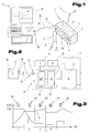
- FIGS. 1 and 2 a charging device 1 for charging electrochemical voltage sources or accumulators and a computing unit 2 in communication with the charging device 1 are exemplified.
- the charging device 1 has, as is known, in a housing 3 an electronic Circuit on, with which the taken over a power cord 4 from an electrical power supply network, electrical energy can be charged in an adequate form in an electrochemical energy storage, in particular in an accumulator, not shown.
- at least one charging line 5, 6 is formed between the electrical circuit of the charging device 1 and the rechargeable battery.
- the electrical circuit of the charging device 1 essentially comprises an electronic control device 7 and an electronic power part 8.
- the electronic, controllable power part 8 of the charging device 1 may e.g. be formed by a so-called clocked power supply.
- the charging behavior or the mode of operation of the power section 8 is influenced or determined by the electronic control device 7, which is preferably formed by a microprocessor control.
- the loading device 1 may optionally comprise an operating device 9, e.g. Buttons, switches and / or rotary or slide control include to manually affect the performance of the charging device 1 by an operator can.
- the charging device 1 may also include a display device 10, e.g. have a display and / or lighting elements for a state of charge or operating state visualization.
- the optionally present operating and / or display device 9, 10 is connected to the control device 7 and / or the power part 8 line connected, as best seen in FIG. 2 can be seen.
- the control device 7 preferably comprises a software-controlled microcontroller 11, which determines the operation of the power unit 8 and thus the charging behavior of the charging device 1 significantly.
- the sequence program or the software of the microcontroller 11 is stored in an electronic memory device 12, which may be arranged externally and / or integrated in the microcontroller 11.
- a control program or a control data record is stored in a memory device 12, which is executable or processable by the microcontroller 11 and thus determines the operating behavior of the charging device 1 significantly.
- the storage device 12 can also buffer or permanently store data.
- the memory device 12 consists at least partially of a permanent, non-volatile memory, such as an EEPROM or flash memory or other, non-volatile write and read memory for sequence programs and / or data of the microcontroller 11th
- the charging device 1 further comprises at least one data interface 13, which is connected to the electronic circuit, in particular to the control device 7 of the charging device 1.
- the data interface 13 is line-connected to the microcontroller 11 or to the memory device 12 in order to be able to write at least data to the memory device 12 and optionally to read out data from the memory device 12 and to provide it to the data interface 13.
- at least one unidirectional data interface 13, but preferably a bidirectional data interface 13 is implemented on the charging device 1.
- the data interface 13 of the charging device 1 is preferably formed by a contact-type interface and designed as an electrical plug-in device 14, as shown in FIG. 2 can be seen.
- the data interface 13 can be formed by any data communication interfaces known from the prior art, such as e.g. be formed by an RS232 interface or by a USB interface.
- the data interface 13 may also be formed by a wireless communication interface and e.g. be executed as radio or infrared or ultrasonic interface.
- a wireless communication interface e.g. be executed as radio or infrared or ultrasonic interface.
- the charging device 1 via the data interface 13 and a cable 15 with the arithmetic unit 2 in communicative or data-technical connection can be set.
- the arithmetic unit 2 is preferably formed by a standardized computer, for example by a personal computer, such as a laptop or a desktop PC or by a handheld computer in the manner of a PDA (Personal Data Assistant), a mobile industrial terminal or the like , It is essential that the arithmetic unit 2 is formed by a standardized, software-controlled Rechariatichtung available on the market.
- This general-purpose computing unit 2 comprises at least one memory device 16 on which programs and / or data are stored or storable.
- the storage device 16 is suitable for receiving user-specific data or software programs.
- the arithmetic unit 2 is provided for executing the software programs stored on this memory device 16.
- At least one of the software programs of the storage device 16 is provided for configuring or influencing the operating behavior of the charging device 1.
- the memory device 16 comprises a software module 17, which can be called up by the arithmetic unit 2, in particular can be executed and visualized on a computer-side screen or display.
- Settings for the operating behavior of the charging device 1 can be made or existing settings can be changed by means of this software module 17 described in more detail below or with the computer-side parameterizing software.
- This software module 17, which is embodied at least in the manner of a parameterization software, thus serves to influence or configure the operating behavior of the charging device 1.
- Control device 7 can be generated and / or changed.
- the parameter values respectively set on the parameterization software or on the arithmetic unit 2 or a data set containing these settings or, if appropriate, a unique identifier representing these settings, can then be transferred or loaded into the loading device 1 via a standardized data interface 18 of the arithmetic unit.
- the parameter values set or selected in the parameterization software are loaded into the charging device 1 or its control device 7 via the data interface 18 of the arithmetic unit 2 and stored permanently, ie non-volatile, in its memory device 12.
- the settings or data loaded into the memory device 12 then influence the mode of operation or the operating behavior of the charging device 1, ie that the charging characteristic of the charging device 1 at least partially, but preferably, via the settings made on the arithmetic unit 2 and subsequently transferred to the charging device 1 is determined decisively.
- the data interface 18 of the arithmetic unit 2 is executed physically or technically identical to the data interface 13 on the charging device 1.
- the arithmetic unit 2 can preferably be placed in a communicative or data-technical connection via a serial interface, for example via an RS232 interface or via a USB interface with the charging device 1.
- the charging device 1 is in any case operable on its own or independently. After activation or commissioning of the charging device 1, this operates according to the transferred charging characteristics.
- bidirectional communication via the data interfaces 13, 18 is preferably made possible.
- the software module 17 running on it and via the data interfaces 13, 18 also an "upload" of data or settings starting from the loading device 1 into the arithmetic unit 2 is made possible. That the settings or parameter values stored in the loading device 1 can be read and visualized by the arithmetic unit 2 in order to be able to make checks and, if necessary, make changes.
- FIG. 3 illustrates a possible charging characteristic for the charging device 1. This figure will be described below in conjunction with FIGS. 1, 2.
- the illustrated charging characteristic can be selected via the computer software module 17 or by means of the parameterization software and / or can be generated with respect to the parameter values.
- IUIoU characteristic This charging characteristic defines certain charging cycles in which the charging voltage or the charging current is regulated or kept constant to predetermined values in order to achieve an efficient and gentle charging of the rechargeable battery.
- the respective parameter values or specifications are stored in the control device 7 of the charging device 1.
- other charging characteristics known from the prior art can also be selected via the parameterizing software, optionally changed and transferred via the data interfaces 18, 13 into the control device 7 of the charging device 1.
- the current or the voltage for the accumulator is kept constant in each case and, after reaching the full charge threshold, a phase for trickle charge is started.
- FIGS. 4 to 7, which are described in conjunction with FIGS. 1 to 3, show program masks of the parameterization software or of the software module 17 which can be run on the computing unit 2 for general purposes - see FIG. 1 - and for the configuration or setting of the charging device 1 - see Fig. 1 - serves, exemplified.
- the software module 17 also includes an authorization checking means 19 in order to be able to check an access authorization or authorization for an operation of certain routines of the software module.
- This authorization checking means 19 can, as shown in FIG. 4, be formed by a registration mask 20.
- this log-on mask 20 e.g. enter a user name 21 and an associated password 22 in order to gain access to security-critical or use-critical functions of the software module 17 or to be able to accomplish a call of the software module 17 at all.
- the authorization checking means 19 may identify an operator or to check the access rights to the software module 17 by means of electronic hardware, in particular by means of an electronic key, such as an electronic key.
- the authorization checking means 19 can also be implemented in the software module 17 in such a way that an authorization check is carried out before the operation of the software module 17 and an operation of the software module 17 is made possible only on the condition of a positively completed authorization check.
- the means 19 for checking the authorization against the usability of the software module 17 can also be formed by a standard system routine of the arithmetic unit 2, such as by a standard password query of the operating software of the arithmetic unit 2.
- the authorization checking means 19 it is also possible to use the authorization checking means 19 then to automatically call the software module 17 if the user has desired or selected a transmission of the settings or parameter values into the loading device 1.
- the authorization checking means 19 can be activated or the user can be requested to prove authorization. Thereupon, a valid, electronic key or an identification by means of user name 21 and password 22 or by means of the access code 23 is required in order to transfer the settings made or the created charging characteristics for future uses functionally effective in the control device 7 of the charging device 1 can.
- the name, in particular the user name 21, and / or another identifier of a user or a user performing the settings of the software module 17 is also transmitted to the control device 7 and permanently stored in the loading device 1.
- these user or retainer-specific data are loaded, starting from the arithmetic unit 2 or starting from the software module 17 via the data interfaces 18, 13 in a non-volatile memory device 12 of the charging device 1 and permanently stored for any subsequent verification or investigation purposes.
- the settings or parameter values and / or the name or code of at least one last valid assignee or authorized user, which was stored in the storage device 12 of the charging device 1, via the data interfaces 13, 18 in the arithmetic unit 2 are transmitted to visualize this data via the software module 17. That the respective settings or parameter values and / or the user-specific data of a user who has selected or activated these charger settings can be read out of the charging device 1 via the software module 17 and the arithmetic unit 2 and used for checking or tracking purposes on the arithmetic unit 2, especially on the screen.
- this authorization checking means 19 can also be implemented by an operator registered with the manufacturer or provider of the software module 17 and the charging device 1, in order to obtain the necessary authorization to create own characteristics or the authorization to change charging characteristics.
- This registration in the software module 17 or at the provider of the software is advantageous in the case of an error caused by a characteristic curve or damage, such as a battery was overloaded or destroyed or other property or personal injury occurred, the person in charge easily and undisputed to locate and notify.
- Operators or customers registered with the provider of the software module 17 or the parameterization software can also acquire simple access to software updates or receive news and other notifications.
- the named services are preferably retrievable via a global data transmission network, in particular via the Internet and the arithmetic unit 2.
- the software module 17 or the parameterization software also includes a plausibility check means 24, which is associated with at least some input fields or input masks of the parameterization software.
- This plausibility check means 24 is associated with at least the input fields for charging voltage or charging current, in order to exclude incorrect or excessive or too low input values or to be able to give the user at least a corresponding warning.
- This plausibility check means 24 checks the selected or intended settings with regard to the type and / or the technical data of the accumulator to be charged and / or with regard to the charging device 1 to be configured. If the software-based plausibility check means 24 of the software module 17 detects impermissible settings, These are either not accepted at all by the software module 17 or by the parameterization software 17 or such impermissible settings can not be transferred to the charging device 1 or stored in the control device 7. Alternatively or in combination with this, the software module 17 or the parameterization software may indicate to a user or operator of the parameterization software that he has selected an inadmissible, safety-critical or possibly damage-causing setting. This automated plausibility check via the software-based plausibility check means 24 is thereby automatically adjusted depending on the respective type of the charging device 1 or in combination with the type or nature of the battery to be charged.
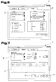
- FIGS. 5 and 6 illustrate in detail possible configuration or parameterizing masks for the configuration or selection of the respective charging device 1.
- the corresponding charger type can be selected and then its technical basic data can be set or displayed, provided that these are already stored as a data set in the arithmetic unit 2.
- the configuration mask according to FIG. 6 it is possible, among other things, to select or define whether there is an indicator on the charging device 1 or which type of display the charging device 1 has and which additional technical components are installed on the charging device 1. It is also possible to select whether a circulation of the electrolyte of the accumulator is to be carried out via the charging device 1.
- the respective values or data can be transmitted to the charging device 1 test-wise or permanently by activating or activating a corresponding button 25 of the parameterization software.
- the configuration or parameterization screens of the parameterization software or the software module 17 are composed, inter alia, of selection fields for a device type 26, for a display type 27, a performance data field 28, an option field 29 and the like.
- the respective charging device 1 can be parameterized or configured with regard to their technical properties and data and then these settings or values can be permanently transferred to the charging device 1, to be referred to below as so-called firmware from the Control device 7 of the charging device 1 to be executed during operation.
- the software module 17 can also function as setup software or as a test program for corresponding charging devices 1.
- the masks illustrated in FIGS. 5 and 6 can, however, also be used for retrieving or reading out the respective technical data or settings of a charging device 1 connected to the arithmetic unit 2.
- Program masks for selecting, recreating or changing charging characteristics are illustrated in FIGS. 7 and 8, as can be implemented in the software module 17 or in the parameterization software for the computing unit 2.
- a characteristic selection field 30 is contained, via which predefined data stored on the arithmetic unit 2 and retrievable by the software module 17 Charging characteristics can be selected and called. Furthermore, a characteristic description field 31 is executed in which at least a brief description of a single or all of the predefined charging characteristics can be seen.
- the program mask according to FIG. 7 within the computer-side software module 17 for the charging device 1 further comprises at least one button 32 for recreating characteristics and at least one button 33 for processing or changing predefined, on the arithmetic unit 2 or in the software module 17 or in the Charger 1 stored charging characteristics.
- a charge mask generating mask 34 is exemplified.
- This creation or processing mask 34 is part of the executable on the arithmetic unit 2 software module 17 and the parameterization software on the arithmetic unit 2 for general purposes.
- a sequence number of the load characteristic to be changed or created can be input, as was illustrated using the selection field 35.
- the characteristic type i. Enter or select the type of current or voltage characteristic.
- Each of the charging characteristics begins with the identifier IU.
- the desired or required characteristic curve is selectable or adjustable.
- IUIoU charging characteristic as exemplified in FIG. 3, can be selected or set to define the desired or required characteristic type.
- the corresponding parameter values for the selected or entered characteristic type according to input field 36 are to be selected or entered below.
- the desired values are to be entered into the current or voltage fields 37, 38, 39, 40.
- these current or voltage fields 37 to 40 which represent the various charging cycles or charging phases of the selected charging characteristic, are, for example, the desired charging current, the minimum charging time, the maximum charging time, the voltage rise, a disconnector detection, a behavior when an error or Like., Adjustable.
- input or selection fields 41, 42, 43 for the type of trickle charge and / or equalizing charge or for various other settings.
- the input or selection field 41 for the trickle charge is, among other things, selectable whether no trickle charge, a standard trickle charge or a trickle charge via a sawtooth characteristic of the charging device 1 should be executed.
- a designation for the generated or changed charging characteristic is to be entered, as was illustrated with reference to the input field 44.
- the software module 17 or the parameterization software further comprises a button 45, for example with the designation "Flash” for transmitting or downloading the settings made or the selected charging characteristics in the charging device 1.
- Flash for transmitting or downloading the settings made or the selected charging characteristics in the charging device 1.
- buttons for discarding or deleting and for storing the generated characteristic data from or in the memory device 16 of the arithmetic unit 2 may be formed.
- the communication connection can be terminated via the data interfaces 13, 18, for example by disconnecting the cable 15.
- the charging device 1 has its own, permanently stored operating software or firmware. After switching on the charging device 1, this operating software is loaded by the control device 7 or the configuration data is read from the storage device 12. Furthermore, the corresponding characteristic block or the respective record loaded for the intended charging characteristics. The further operation of the control device 7 then takes place in accordance with these settings or parameter values from the non-volatile memory device 12. The respective control commands or data are then transferred to the power section 8 in order to achieve a corresponding charging characteristic.
- the corresponding operating state data or settings can also be output to an optionally present display device 10 and at least partially changed or adapted by an operator via an optionally formed operating device 9.
- the charging device 1 is in any case fully operational and communication with the arithmetic unit 2 is no longer necessary. Only in the event that the mode of operation or the charging behavior of the charging device 1 is to be changed, the arithmetic unit 2 is again coupled to the charging device 1 and then an adaptation or change in the charging characteristics of the charging device 1 is possible.
- a preferred manner for the technical description or definition of charging characteristics which can be changed according to the invention is described below. The following statements relate to the most important charging or battery parameters, which are of particular importance for changing the characteristic of a charging characteristic:
- the current or voltage fields 37, 38, 39 and the input or selection fields 41, 42 according to FIG. 8 are assigned to the successive charging phases 46 to 50 of the IUIoU charging characteristic exemplified in FIG are.
- the charging phases 46 to 50 for a battery or a charging device 1 can be selected from a group comprising main charge, termination charge, trickle charge and equalizing charge.
- each of these charging phases 46 to 50 at least the respective amplitude values of the current or voltage characteristic can be determined via the software module 17 and also the respectively relevant time periods or time limits for these charging phases 46 to 50 in the software module 17 can be selected or entered are.
- the first charging phase 46 with the software module 17, in particular by means of the current or voltage field 37 it can be defined how high the main charging current I 1 should be, as can easily be seen from the illustration according to FIG is.
- the maximum charging time t 1 can be defined.
- the charging current is kept at least largely constant by the charging device 1.
- the charging voltage of the charging device 1 should be kept at least substantially constant.
- This main charging voltage U 1 can be defined in the current or voltage field 38 according to FIG. 8.
- a minimum charging time t 2 and a maximum charging time t 2 can be defined for this second charging phase 47, as can be seen from FIG. 8.
- the charging current is kept substantially constant at a comparatively lower value-for example 5A according to the uppermost input field of the current or voltage field 39 in FIG. 8.
- a shutdown method can be defined for this third charging phase 48.
- the voltage curve or the voltage increase at the accumulator is monitored within a defined period of time and when exceeding or falling below the respective limit value, this third charging phase 48 is continued or terminated. In particular, this automatically detects whether a complete or almost complete charging of the battery has been achieved or not.
- a minimum charging time and / or a maximum charging time or a maximum voltage can be defined in accordance with the current or voltage field 39 for this third charging phase 48.
- a fourth charging phase 49 can follow, which is preferably defined by a specific period of time for carrying out a trickle charge (EHL).
- This third charging phase 49 can be configured in the input or selection field 41 of the software module 17.
- the type of trickle charge namely, no trickle charge, trickle charge trickle charge, standard trickle charge, and the like, can be selected here.
- a threshold value for a switch-on voltage and a switch-off voltage based on the cell voltage of the battery to be charged, can be defined. So thresholds for the activation and deactivation of the trickle charge are set.
- the maximum charging current, the minimum pulse duration, the maximum pulse duration and the maximum time for the pulse operation in the input or selection field 41 for the charging phase 49 regarding the optionally activatable trickle charge can be defined.
- a fifth charging phase 50 can also be defined.
- the respective parameters have been exemplified in FIG. 8 in the input or selection field 42.
- it can be set in the software module 17 whether a charge phase 50 with regard to equalization charge (AGL) for the battery to be charged is desired or not.
- this function can be activated or deactivated via the software module 17 if necessary.
- the charging current, the charging time, the maximum voltage and the delay for this charging phase 50 can be set with the compensation charge.
- the equalizing charge When the equalizing charge is active, the energy removed from a battery is at least partially or completely recharged or the load connected to the battery is at least partially supplied via the charging device 1, provided that the charging phase 50 is active for equalizing charge.
- the charging device 1 provides with active equalizing charge (AGL) - charging phase 50 - so the increased demand for energy and still prevents overcharging of the battery.
- the further current or voltage field 40 of the software module 17 is not required or not applicable for a setup or a compilation of the initially selected characteristic type, in particular for the IUIoU characteristic to be defined in detail, and is therefore user-defined in this section Creation or processing mask 34 to make any entries.
- the software module 17 or the software-controlled device e.g. formed in the manner of a commercially available arithmetic unit 2, for the preparation of the respective selection or setting values corresponding, composed of several charging phases 46 to 50 charging characteristic and provided for transmitting the same to a previously defined type of charging device 1.
- the type selection concerning the respective structure of the charging apparatus 1 to be configured has been exemplified by the selection box 26 concerning "apparatus type" in FIG.
- the creation or processing mask 34 for the definition of the characteristics of charging characteristics may include a software-based plausibility check means 24.
- This plausibility check means 24 is actively implemented for at least some input fields, eg regarding the main charge current and the main charge voltage.
- this software-based plausibility check means 24 ensures that inaccurate or possibly even damage-causing settings can not be entered or are not transferable to the charging device 1. It is advantageous if an acoustic and / or optical warning or error signal is output when inputting an incorrect or excessive value from the arithmetic unit 2 (see FIG. 1) or controlled by the software module 17. As a result, a particularly user-friendly and secure software module 17 is created. Furthermore, this prevents that the choice of high charging currents or high charging voltages depending on the type of battery to be charged with the charging device 1 leads to destruction or damage.
- a fault behavior 51 can be defined.
- the preferred embodiment of the charging device 1 is designed to automatically monitor the current charging processes.
- a suitably predefined measure is initiated automatically by the charging device 1 in the event of detection or automatic detection of an error.
- a specific measure in particular a countermeasure or another remedy, can be initiated automatically depending on the respective error.
- an automatically initiated measure for example, by a switch to trickle charging (EHL), ie defined by a change to the charging phase 49.
- EHL switch to trickle charging
- a restart of the charging process can be carried out automatically in the event of an error.
- a switch to trickle charging (EHL) can be configured via the software module 17 and subsequently converted accordingly by the charging device 1 programmed therewith.
- a termination or termination of the charging process can be carried out automatically if this has been selected or activated via the selection field relating to fault behavior 51 and these data or settings via the software module 17 and the Arithmetic unit 2 were transferred to the charging device 1.
- Which of the possible error behavior 51 is to be automatically implemented when a fault is detected can be set in the software module 17 or in the creation or processing mask 34 according to the respective requirements by the user.
- a software-based plausibility check means 24 is preferably designed, so that the setting or configuration of an incorrect fault behavior 51 is automatically prevented or can not be implemented by the charging device 1 ,
- the arithmetic unit 2 can also be incorporated in a simple manner into a global data transmission network, such as e.g. the Internet, to be involved. Alternatively, it is also conceivable to switch the charging device 1 itself into a data transmission network. As a result, a particularly error-free modification of the charging behavior of the charging device 1 is achieved and it is also possible that such updates or reconfigurations can be performed easily and fail-safe even by laymen who have no special expertise in charging technology for batteries.
- FIGS. 1, 2; 3; 4; 5, 6; 7, 8 can form the subject of independent solutions according to the invention.
- the relevant objects and solutions according to the invention can be found in the detailed descriptions of these figures.
Abstract
Description
Die Erfindung betrifft ein Verfahren zur Konfiguration des Betriebsverhaltens einer Ladevorrichtung für Akkumulatoren, eine softwaregesteuerte Vorrichtung zur Konfiguration der Betriebsweise einer Ladevorrichtung für Akkumulatoren, eine Ladevorrichtung für Akkumulatoren und ein System zur Durchführung des einleitend genannten Verfahrens, wie dies in den Ansprüchen 1, 16, 24 und 29 beschrieben ist.The invention relates to a method for configuring the operating behavior of an accumulator charging device, a software-controlled device for configuring the operation of an accumulator charging device, a charging device for accumulators and a system for carrying out the method mentioned in the introduction, as in
Es sind Ladevorrichtungen für Akkumulatoren, insbesondere industrielle Ladevorrichtungen bekannt, welche anhand einer in der elektronischen Steuervorrichtung hinterlegten, vorprogrammierten Steuersoftware das jeweils erforderliche Ladeverhalten umsetzen. Ferner sind Ladevorrichtungen bekannt, die mittels einer Mehrzahl von außen zugreifbaren bzw. teilweise integrierten und somit nur einem unterwiesenen bzw. beschränkten Benutzerkreis zugänglichen Einstellelementen eine Konfiguration bzw. Veränderung des Ladeverhaltens ermöglichen. Diese beispielsweise durch Schalter, DIP-Switches, Drehregler oder dgl. ausgeführten Einstellelemente sind zumeist innerhalb des Gehäuses angeordnet und nur nach dem Abnehmen oder Öffnen von Gehäuseteilen zugänglich. Dadurch sollen unbefugte, einschneidende Veränderungen der Eigenschaften der Ladevorrichtung möglichst unterbunden werden. Bei von außen zugänglichen Einstellelementen bzw. bei unbeabsichtigter, unbefugter oder unfachmännischer Veränderung des Ladeverhaltens besteht erhöhte Gefahr einer unzulässigen Veränderung des Betriebsverhaltens der Ladevorrichtung, wodurch Schäden an der Ladevorrichtung selbst oder an den zu ladenden Akkumulatoren bzw. sogar an peripheren Vorrichtungen verursacht werden können, wenn der Akkumulator durch eine fehlerhafte Aufladung unbrauchbar bzw. zerstört wird.There are charging devices for batteries, especially industrial charging devices known, which convert based on a stored in the electronic control device, preprogrammed control software the respective required charging behavior. Furthermore, charging devices are known which allow a configuration or change of the charging behavior by means of a plurality of externally accessible or partially integrated and thus accessible only to a trained or limited user group adjustment elements. These, for example, by switches, DIP switches, knobs or the like. Running adjusting elements are usually located within the housing and accessible only after removal or opening of housing parts. This should prevent as far as possible unauthorized, drastic changes in the characteristics of the charging device. In externally accessible adjustment or inadvertent, unauthorized or unprofessional change in the charging behavior is increased risk of improper change in the performance of the charging device, which may cause damage to the charger itself or to be charged batteries or even to peripheral devices, if the accumulator is unusable or destroyed by a faulty charging.
Grundsätzlich ist zu erwähnen, dass bei den bekannten Ladegeräten bzw. gemäß den bekannten Verfahren vom Produzenten des Ladegerätes erstellte Kennlinien direkt im Herstellerwerk in das Ladegerät gespeichert werden. Hierzu wird das Ladegerät mit einem Programmiergerät, das beispielsweise durch einen PC gebildet sein kann, über eine Datenschnittstelle verbunden, sodass anschließend eine oder mehrere Kennlinien vom werksseitigen Programmiergerät über eine Schnittstelle in das Ladegerät gespeichert werden. Diese Kennlinien kann der Benutzer beim Einsatz des Ladegerätes anschließend auswählen und eventuell über diverse Bedienelemente am Ladegerät an die zu ladende Batterie anpassen.Basically, it should be mentioned that in the known chargers or in accordance with the known methods produced by the manufacturer of the charger characteristics are stored directly in the factory in the charger. For this purpose, the charger is connected to a programming device, which may be formed for example by a PC, via a data interface, so that then one or more characteristics are stored by the factory-side programming device via an interface in the charger. These characteristics can be the Then select user when using the charger and possibly adapt to the battery to be charged via various controls on the charger.
Weiters ist es bereits bekannt, dass ein Benutzer selbst das Ladegerät mit einem PC verbindet und über eine auf einem PC installierte Software geringfügige Anpassungen der Spannungshöhe und/oder der Stromhöhe vornimmt, also eine Verschiebung der Amplitudenhöhen der Ladekennlinie vornehmen kann. Die Charakteristik der Ladekennlinie bleibt dabei jedoch unverändert und kann der Benutzer die in der Spannungs- bzw. Stromhöhe entsprechend angepasste Kennlinie nachfolgend wieder an das Ladegerät übertragen und speichern. Durch ein derartiges Vorgehen wird erreicht, dass der Benutzer eine gewisse Anpassung der Kennlinie und eine Speicherung der geänderten Kennlinie im Ladegerät vornehmen kann, sodass er diese Veränderungen bzw. Anpassungen nicht für jeden Ladevorgang erneut vornehmen muss.Furthermore, it is already known that a user himself connects the charger to a PC and makes minor adjustments to the voltage level and / or the current level via a software installed on a PC, that is, can shift the amplitude levels of the charging characteristic. However, the characteristic of the charging characteristic remains unchanged and the user can subsequently transfer and store the voltage curve correspondingly adapted to the voltage or current level again to the charger. Such a procedure ensures that the user can make a certain adjustment of the characteristic curve and a storage of the changed characteristic in the charger so that he does not have to make these changes or adjustments again for each charging process.
Nachteilig ist hierbei, dass vom Benutzer lediglich eine Kennlinienverschiebung durchgeführt werden kann, also nur geringfügige Änderungen der Kennlinienamplitude möglich sind, wobei für ein derartiges Vorgehen ein erhöhter Aufwand erforderlich ist, nachdem eine Verbindung des Ladegerätes mit einem PC aufgebaut werden muss und eine derartige Amplitudenveränderung in einfacher Art und Weise auch über ein Einstellelement für den Ladestrom und ein Einstellelement für die Ladespannung am Ladegerät selbst durchgeführt werden kann. Weitere Einstellmöglichkeiten der Kennlinie, insbesondere eine Veränderung der Ladecharakteristik bzw. des Kennlinienverlaufes, sind über diese bekannte Software-Programmierung nicht möglich.The disadvantage here is that the user can only perform a characteristic shift, so only minor changes in the characteristic amplitude are possible, for such a procedure, an increased effort is required after a connection of the charger with a PC must be established and such a change in amplitude a simple way can also be performed via a setting element for the charging current and a setting element for the charging voltage on the charger itself. Further adjustment of the characteristic curve, in particular a change in the charging characteristic or the characteristic curve, are not possible via this known software programming.
Der vorliegenden Erfindung liegt die Aufgabe zugrunde, eine fehlersichere Einstellung von Ladekennlinien an einer Ladevorrichtung für Akkumulatoren zu erzielen, ohne dadurch die Gerätekosten, insbesondere den Hardwareaufwand für die Ladevorrichtung, wesentlich zu erhöhen. Eine weitere, insbesondere davon unabhängige Aufgabe der Erfindung liegt darin, eine möglichst flexible Einstellung der Ladekennlinie zu ermöglichen, um Vorort eine Anpassung der Ladekennlinie des Ladegerätes an den jeweiligen Akkumulator vornehmen zu können oder eine benutzerspezifische Ladekennlinie erstellen zu können. Eine weitere Aufgabe der Erfindung liegt darin, dass ein OEM-Partner eines Ladegeräte-Herstellers für seine Kunden bzw. Anwendungsfälle eigenständig entwickelte Kennlinien in einem Ladegerät umsetzen kann.The present invention has for its object to achieve a fail-safe setting of charging characteristics of a charging device for batteries, without thereby significantly increase the cost of equipment, in particular the hardware costs for the charging device. A further, in particular independent, object of the invention is to make it possible to set the charging characteristic as flexible as possible in order to be able to adapt the charging characteristic of the charger to the respective accumulator in suburb or to create a user-specific charging characteristic. Another object of the invention is that an OEM partner of a charger manufacturer can implement independently developed characteristics in a charger for his customers or applications.
Die jeweilige Aufgabe der Erfindung wird durch die Maßnahmen gemäß Anspruch 1, durch eine Vorrichtung nach Anspruch 16 bzw. durch eine Ladevorrichtung nach Anspruch 24 gelöst.The respective object of the invention is achieved by the measures according to
Vorteilhaft ist dabei, dass umfangreiche Einstellhardware, wie z.B. Schalter, Taster, Dreh- bzw. Schieberegler, zur Veränderung des Ladeverhaltens der Ladevorrichtung gegebenenfalls sogar gänzlich erübrigt werden kann, sodass die gesamten Hardwarekosten für die Ladevorrichtung reduziert werden können. Alternativ ist es zwar auch möglich, parallel zur softwaregesteuerten Konfiguration über die standardmäßige Recheneinheit, auch an der Ladevorrichtung eine hardwarebasierende Konfiguration der Ladekennlinien zu ermöglichen. In einem derartigen Fall stellt die Hardwareparametrierung an der Ladevorrichtung parallel zum Softwaremodul für die allgemeine Recheneinheit eine mögliche Option dar. Nachdem eine hardwaremäßig ausgeführte, relativ leicht zugängliche Bedienerschnittstelle mit Potentiometer, Schalter und dgl. nicht mehr zwingend erforderlich ist, wird auch die Gefahr von Fehleinstellungen durch ungeschulte bzw. unbefugte Benutzer bzw. die Gefahr von unbeabsichtigten Veränderungen der korrekten Einstellungen minimiert. Schäden am Gerät bzw. an den zu ladenden Akkumulatoren können dadurch mit erhöhter Sicherheit vermieden werden, obwohl grundsätzlich ein kostengünstigerer bzw. einfacherer Aufbau der Ladevorrichtung möglich ist. Von besonderem Vorteil ist weiters, dass ein Anwender bzw. Anbieter eines erfindungsgemäßen Systems die Möglichkeit erhält, eigens erstellte bzw. individuell angepasste Ladekennlinien, welche den jeweiligen Anforderungen möglichst optimal entsprechen, jederzeit erstellen zu können. Insbesondere ist die Bildung mehrerer Varianten von Ladekennlinien bzw. Ladecharakteristiken durch einen Bediener der Software bzw. der Ladevorrichtung einfach möglich. Von besonderem Vorteil ist weiters, dass ein OEM-Partner bzw. ein OEM-Anbieter kein ladetechnisches Know-How an den Produzenten des Ladegerätes weitergegeben werden muss, um die entsprechende Ladekennlinie optimal umsetzen zu können. Insbesondere können vom Hardware-Lieferanten Standardkomponenten eingesetzt werden, woraus der OEM-Partner ein entsprechendes Ladegerät zusammenstellen kann und die entsprechenden Kennlinien für sich eigenständig programmieren kann. Ferner lässt sich durch die erfindungsgemäßen Maßnahmen eine entsprechende Ladevorrichtung durch eine Übertragung bzw. einen einfachen Download einer neuen Ladekennlinie stets bzw. längerfristig auf dem aktuellen Stand der Technik halten. Bereits an Lieferanten oder Kunden ausgelieferte Geräte brauchen somit nicht mehr zurück zum Hersteller gesendet werden, um eine Optimierung des Ladeverhaltens zu programmieren. Beispielsweise ist eine relativ einfache Anpassung an neue Batterietechnologien bzw. an aktuelle Erkenntnisse aus der Ladetechnologie problemlos möglich, indem man diese Neuerungen in das technische Verhalten der Ladevorrichtung einfließen lässt. So ist z.B. eine einfache Optimierung der Ladekennlinien möglich, indem die jeweilige Kennlinien bzw. die gewünschten Werte verändert werden und die neuen Daten in das Ladegerät übertragen werden. Durch die vor allem für befugte Benutzer bei Bedarf optimierbaren Kennlinien bzw. Kennlinien-Phasen können auch längere Lebensdauern bzw. höhere Ladekapazitäten für die Akkumulatoren erreicht werden, als würden unterschiedliche Batterietypen jeweils mit der gleichen Kennlinie aufgeladen werden. Nicht zuletzt durch die hochflexible und erforderlichenfalls sogar besonders detaillierte, softwarebasierende Konfigurationsmöglichkeit der Ladecharakteristik können auch Kleinserien einer bestimmten Ladegerätetype relativ kostengünstig und problemlos zur Verfügung gestellt werden bzw. sind spezielle Ladegerätetypen ohne besondere hardwaretechnische Veränderungen ebenso realisierbar. Dies stellt sich als weiterer Nutzen für den Produzenten bzw. Anbieter einer erfindungsgemäßen Ladevorrichtung dar. Ferner ist von Vorteil, dass trotz des Umstandes, dass unterschiedliche Ladevorrichtungen häufig unterschiedliche Kennlinienformen bzw. unterschiedliche Kennlinien-Phasen erfordern, eine Anpassung an die jeweilige Ladevorrichtung ermöglicht ist, sodass ein einziges Softwaremodul für mehrere, baulich unterschiedliche Ladevorrichtungen eingesetzt werden kann.It is advantageous that extensive Einstellhardware, such as switches, buttons, rotary or slider, to change the charging behavior of the charging device may possibly even be completely unnecessary, so that the total hardware costs for the charging device can be reduced. Alternatively, it is also possible to enable a hardware-based configuration of the charging characteristics parallel to the software-controlled configuration via the standard arithmetic unit, also on the charging device. In such a case, the hardware parameterization on the loader parallel to the software module for the general processing unit is a possible option. After a hardware executed, relatively easily accessible user interface with potentiometer, switch and the like. No longer is mandatory, also the risk of incorrect settings minimized by untrained or unauthorized users or the risk of unintentional changes in the correct settings. Damage to the device or to the batteries to be charged can be avoided with increased security, although in principle a cheaper or simpler construction of the charging device is possible. It is also of particular advantage that a user or provider of a system according to the invention obtains the possibility of being able to create specially created or individually adapted charging characteristics which correspond optimally to the respective requirements at any time. In particular, the formation of multiple variants of charging characteristics or charging characteristics by an operator of the software or the charging device is easily possible. Of particular advantage is further that an OEM partner or an OEM provider no charging technology know-how must be passed to the manufacturer of the charger to optimally implement the corresponding charging characteristic. In particular, standard components can be used by the hardware supplier, from which the OEM partner can assemble a corresponding charger and program the corresponding characteristic curves independently. Furthermore, the measures according to the invention make it possible to keep a corresponding charging device always or longer in the current state of the art by transmitting or simply downloading a new charging characteristic. Devices already delivered to suppliers or customers do not need to be sent back to the manufacturer to optimize the To program charging behavior. For example, a relatively simple adaptation to new battery technologies or to current findings from charging technology is easily possible by incorporating these innovations into the technical behavior of the charging device. For example, a simple optimization of the charging characteristics is possible by changing the respective characteristic curves or the desired values and transferring the new data to the charger. Longer lifetimes and / or higher charging capacities for the accumulators can be achieved by the characteristic curves or characteristic phases, which can be optimized, in particular for authorized users, as if different types of batteries were each charged with the same characteristic curve. Not least by the highly flexible and, if necessary, even more detailed, software-based configuration possibility of the charging characteristic even small series of a particular type of charger can be provided relatively inexpensive and easily available or are special charger types without special hardware technical changes also feasible. This proves to be a further benefit for the producer or supplier of a charging device according to the invention. Furthermore, it is advantageous that, despite the fact that different charging devices often require different characteristic shapes or different characteristic phases, an adaptation to the respective charging device is made possible, so that a single software module for multiple, structurally different charging devices can be used.
Von Vorteil sind auch die zusätzlichen Maßnahmen gemäß Anspruch 2, da über diese softwarebasierende Definition von Grenzwerten für Batterie-Unterspannung und Batterie-Überspannung in Abhängigkeit von bestimmten Temperaturverhältnissen eine optimale Aufladung der Batterie bzw. ein zuverlässiger Schutz derselben vor einer Überladung in einfacher Art und Weise bewerkstelligt ist.Also advantageous are the additional measures according to
Vorteilhaft sind aber auch die Maßnahmen nach Anspruch 3, da dadurch sichergestellt ist, dass sich nach dem Erreichen des vollständig geladenen Zustandes der Batterie, woraufhin die Ladespannung bevorzugt abgesenkt wird, automatisch eine Ladephase für Erhaltungsladung anschließt. Dies erbringt den Vorteil, dass die Selbstentladung der Batterie durch eine solche Erhaltungsladung zumindest weitgehendst ausgeglichen wird und die Batterie somit ständig einsatzbereit bzw. stets vollständig geladen ist. Weiters ist von Vorteil, dass eine für eine automatische Erhaltungsladung konfigurierte Ladevorrichtung beliebig lange an der Batterie angeschlossen bleiben kann, sodass von einem Benutzer keinerlei Kontroll- bzw. Abschaltmaßnahmen nach dem Erreichen des Vollladezustandes notwendig sind.But also advantageous are the measures according to
Von Vorteil sind auch die weiterführenden Maßnahmen gemäß Anspruch 4, da dadurch softwaremäßig konfigurier- und definierbar ist, ob eine Ladevorrichtung eine Ausgleichsladung vornehmen soll, falls der an die Ladevorrichtung angeschlossenen Batterie von einem Verbraucher elektrische Energie entnommen wird. Die in einfacher Art und Weise softwaremäßig entsprechend konfigurierte Ladevorrichtung liefert sodann den Mehrbedarf an Strom bzw. an Energie und verhindert dennoch ein Überladen der mit der Ladevorrichtung verbundenen Batterie.Another advantage is the further measures according to
Von Vorteil sind auch die Maßnahmen gemäß Anspruch 5, da dadurch eine Ladevorrichtung problemlos auf jene Werte konfiguriert bzw. adaptiert werden kann, welche vom Hersteller der jeweils zu ladende Batterie vorgeschrieben bzw. empfohlen wurden, um eine schonende, aber dennoch rasche und effiziente Aufladung der Batterie zu erzielen. Unabhängig davon kann eine Ladevorrichtung via diese softwaremäßige Konfigurationsmöglichkeit von Ladecharakteristiken auch auf andere Werte, welche sich z.B. gemäß Erfahrungswerten aus der Praxis bewährt haben, jederzeit adaptiert werden.The measures according to
Von besonderem Vorteil sind auch die Maßnahmen gemäß Anspruch 6, da dadurch von einem Bediener des Softwaremoduls einfach festgelegt werden kann, wie sich eine mit diesem softwarebasierenden Werkzeug konfigurierte Ladevorrichtung beim Auftreten eines Fehlers verhalten soll. Gegebenenfalls können dadurch auch ältere Batterien bzw. Batterien, welche bereits seit längerer Zeit im Einsatz sind und daher von den Idealwerten gemäß dem anfänglichen Gebrauch vielfach etwas abweichen, dennoch vollständig bzw. bestmöglich geladen werden. Darüber hinaus kann durch die benutzerseitige Einstellung des jeweiligen Fehlerverhaltens passend reagiert werden, wenn von der Ladevorrichtung untypische Ladeprozesse bzw. Batteriezustände detektiert werden. Insbesondere ist eine derartige Fehlererkennung einer Ladevorrichtung durch eine automatische Überwachung des Ladestroms, der Batteriespannung und/oder der Temperatur an der Batterie definiert. Gemäß einer vorteilhaften Ausführungsform weist die Ladevorrichtung wenigstens ein Temperaturerfassungsmittel auf, mit welchem die Batterietemperatur sensorisch erfassbar und auswertbar ist.Of particular advantage are the measures according to
Von Vorteil sind auch die weiterführenden Maßnahmen nach Anspruch 7 und/oder 8, da dadurch die Gefahr von Fehleinstellungen minimiert wird bzw. die Gefahr einer Beschädigung der Ladevorrichtung bzw. der zu ladenden Akkumulatoren deutlich reduziert wird. Eine derartige Plausibilitätsprüfung wäre insbesondere bei einer Umsetzung über eine reine Hardwareschnittstelle zur Veränderung von Einstellungen an der Ladevorrichtung kaum bzw. nur mit beträchtlichem Aufwand möglich.Also of advantage are the further measures according to
Durch die besonderen Maßnahmen nach Anspruch 9 kann der Benutzer auf unzulässige bzw. inadäquate Einstellungen hingewiesen werden und kann es dann im Ermessen des Benutzers bzw. Bedieners liegen, diese Einstellungen abzuändern bzw. beizubehalten, sofern der Hinweis lediglich warnend und nicht verweigernd bzw. ablehnend wirkt.The special measures according to
Von besonderem Vorteil sind auch die Maßnahmen nach einem oder mehreren der Ansprüche 10 bis 13. Dadurch wird erreicht, dass eine Veränderung von Einstellungen durch unbefugte Personen bzw. durch einen nicht sachverständigen Personenkreis sicher und in einfacher Art und Weise unterbunden wird. Etwaige Fehleinstellungen und daraus resultierende Schäden können somit zuverlässig unterbunden bzw. auf ein Minimum reduziert werden, da die entsprechenden Zugriffs- bzw. Bedienungsrechte einem bestimmten Personenkreis vorenthalten werden.Of particular advantage are the measures according to one or more of
Von Vorteil sind auch die Verfahrensschritte nach Anspruch 14, da dadurch stets nachvollzogen werden kann, wer die jeweiligen Einstellungen für die Ladevorrichtungen gewählt bzw. getroffen hat. Beispielsweise bei einem Schadensfall ist eine einfache Rückverfolgbarkeit und Benachrichtigung des jeweiligen Konfigurators der Ladevorrichtung möglich bzw. können sodann umgehende Abstell- bzw. Bereinigungsmaßnahmen ergriffen werden.Also advantageous are the method steps according to
Von Vorteil sind auch die Maßnahmen gemäß Anspruch 15, da durch einen derartigen "Upload" in die standardisierte Recheneinheit die jeweiligen Einstellungen des Ladegerätes komfortabel ausgelesen, kontrolliert, bei Bedarf verändert und wieder in die Ladevorrichtung übertragen werden können.The measures according to
Mit einer softwaregesteuerten Vorrichtung gemäß Anspruch 16 erzielbare Vorteile sind der vorhergehenden Beschreibung zu entnehmen.With a software-controlled device according to claim 16 achievable advantages can be found in the foregoing description.
Bei einer Weiterbildung dieser Vorrichtung nach Anspruch 17 ist von Vorteil, dass eine eindeutige, physikalische Zuordnung zwischen der Recheneinheit und der anzubindenden Ladevorrichtung geschaffen ist, da die Kabelverbindung etwaige Missverständnisse in der Gerätezuordnung weitgehendst ausschaltet. Von Vorteil ist weiters, dass die angegebenen, standardisierten Schnittstellen eine einfache und bewährte Datenübertragung ermöglichen und eine standardmäßige Recheneinheit zur Anbindung an die Ladevorrichtung geeignet ist.In a further development of this device according to
Bei der alternativen Ausgestaltung gemäß Anspruch 18 ist von Vorteil, dass der Manipulationsaufwand zur Herstellung einer datentechnischen Verbindung zwischen der softwaregesteuerten Vorrichtung und einem Aufladegerät, insbesondere zwischen der Recheneinheit und einer Ladevorrichtung minimiert wird.In the alternative embodiment according to
Von besonderem Vorteil ist auch die Weiterbildung nach einem oder mehreren der Ansprüche 19 bis 22. Dadurch wird erreicht, dass der Zugriff auf benutzungs- bzw. verwendungskritische Veränderungsroutinen einem beschränkten bzw. berechtigten Benutzerkreis vorenthalten bleibt. Fehleinstellungen und damit eventuell einhergehende Schäden im Aufladesystem bzw. unzureichende Aufladungen von betriebsrelevanten Akkumulatoren können dadurch in einfacher und zuverlässiger Art und Weise unterbunden bzw. reduziert werden.Of particular advantage is also the development according to one or more of
Durch die vorteilhafte Weiterbildung nach Anspruch 23 wird beim Bediener der softwaregesteuerten Vorrichtung eine erhöhte Bewusstseinsbildung erzielt, sodass leichtfertige Veränderungen der Betriebsweise der Ladevorrichtung hintan gehalten werden können. Darüber hinaus kann die elektronische Hinterlegung bzw. Dokumentation der Einstellerdaten eventuell notwendige Überprüfungs- bzw. Adaptierungsaktionen erleichtern.Due to the advantageous development according to
Effekte bzw. Vorteile, welche mit einer Ladevorrichtung gemäß Anspruch 24 erzielbar sind, wurden vorhergehend beschrieben.Effects or advantages which can be achieved with a charging device according to claim 24 have been described above.
Von Vorteil ist bei einer Weiterbildung der Ladevorrichtung nach Anspruch 25, dass eine Rückverfolgbarkeit betreffend den Bediener der externen, rechnerseitigen Konfigurations- bzw. Parametriersoftware bzw. bezüglich des Einstellers des Ladeverhaltens unzweifelhaft ermöglicht ist.It is advantageous in a further development of the charging device according to claim 25 that traceability with respect to the operator of the external, computer-side configuration or parameterization software or with respect to the adjuster of the charging behavior is undoubtedly made possible.
Von Vorteil ist auch eine Weiterbildung nach Anspruch 26, da dadurch die jeweiligen Einstellungswerte bzw. die Daten des Einstellers einfach ausgelesen werden können und via übersichtliche, rechnerseitige Masken visualisiert und beispielsweise die Ladekennlinien problemlos auch grafisch ausgewertet werden können.Another advantage is also a development according to
Vorteilhaft ist auch eine Ausführung nach Anspruch 27, da dadurch beim Vorhandensein einer bevorzugt grafischen bzw. textbasierenden Anzeigevorrichtung auch ohne Verwendung einer externen Recheneinheit zumindest die vorhandene Konfiguration bzw. die aktuelle Einstellung einfach bestimmt werden kann. Dies kann bei einer Ausgabe von Kennungen via Vergleichstabellen oder mittels Hilfsprogrammen bzw. durch Inanspruchnahme einer Servicedienstleistung des Produzenten bzw. Händlers erfolgen.Also advantageous is an embodiment according to
Durch die Ausgestaltung nach Anspruch 28 ist überdies direkt an der Ladevorrichtung eine Visualisierung bzw. Programmierung von Einstellungen bzw. Ladekennlinien ermöglicht. Die Anbindung einer externen Recheneinheit mit dem entsprechenden Softwaremodul ist somit nicht in allen Fällen erforderlich.Due to the embodiment according to
Die Vorteile eines Systems gemäß Anspruch 29 sind in adäquater Zuordnung aus den vorhergehenden Beschreibungsteilen zu entnehmen.The advantages of a system according to claim 29 can be found in an adequate allocation from the preceding description parts.
Die Erfindung wird im nachfolgenden anhand der in den Zeichnungen dargestellten Ausführungsbeispiele näher erläutert.The invention will be explained in more detail below with reference to the embodiments illustrated in the drawings.
Es zeigen:
- Fig. 1
- eine Ladevorrichtung für Akkumulatoren in datentechnischer Verbindung mit einer Recheneinheit für allgemeine Verwendungszwecke in vereinfachter, schematischer Darstellung;
- Fig. 2
- ein Blockschaltbild des Gerätesystems nach Fig. 1 in schaubildlicher, stark vereinfachter Darstellung;
- Fig. 3
- mögliche Kennlinien für ein an der Recheneinheit einstellbares Ladeverhalten für die Ladevorrichtung;
- Fig. 4
- ein mögliches Berechtigungsüberprüfungsmittel für die Nutzung des auf einer allgemeinen Recheneinheit ablauffähigen Softwaremoduls in vereinfachter, beispielhafter Darstellung;
- Fig. 5
- eine mögliche, softwaretechnische Konfigurationsmaske, welche auf einer allgemeinen Recheneinheit ausführbar ist;
- Fig. 6
- eine weitere mögliche Konfigurationsmaske für eine Ladevorrichtung, die via eine über- bzw. nebengeordnete Recheneinheit konfigurierbar ist;
- Fig. 7
- eine mögliche Programmmaske zur Auswahl einer von mehreren, vordefinierten Ladekennlinien;
- Fig. 8
- eine mögliche Programmmaske zur Neuerstellung bzw. Veränderung von Ladekennlinien einer Ladevorrichtung mittels einer Recheneinheit für allgemeine Verwendungszwecke.
- Fig. 1
- a charging device for accumulators in data communication with a computing unit for general purposes in a simplified, schematic representation;
- Fig. 2
- a block diagram of the device system of Figure 1 in diagrammatic, highly simplified representation.
- Fig. 3
- possible characteristics for a charge behavior for the charging device that can be set on the arithmetic unit;
- Fig. 4
- a possible authorization checking means for the use of executable on a general computing unit software module in a simplified, exemplary representation;
- Fig. 5
- a possible, software technical configuration mask, which is executable on a general computing unit;
- Fig. 6
- Another possible configuration mask for a charging device, which is configurable via a parent or sibling arithmetic unit;
- Fig. 7
- a possible program mask for selecting one of a plurality of predefined charging characteristics;
- Fig. 8
- a possible program mask for the creation or modification of charging characteristics of a charging device by means of a computing unit for general purposes.
Einführend sei festgehalten, dass in den unterschiedlich beschriebenen Ausführungsformen gleiche Teile mit gleichen Bezugszeichen bzw. gleichen Bauteilbezeichnungen versehen werden, wobei die in der gesamten Beschreibung enthaltenen Offenbarungen sinngemäß auf gleiche Teile mit gleichen Bezugszeichen bzw. gleichen Bauteilbezeichnungen übertragen werden können. Auch sind die in der Beschreibung gewählten Lageangaben, wie z.B. oben, unten, seitlich usw. auf die unmittelbar beschriebene sowie dargestellte Figur bezogen und sind bei einer Lageänderung sinngemäß auf die neue Lage zu übertragen. Weiters können auch Einzelmerkmale oder Merkmalskombinationen aus den gezeigten und beschriebenen unterschiedlichen Ausführungsbeispielen für sich eigenständige, erfinderische oder erfindungsgemäße Lösungen darstellen.By way of introduction, it should be noted that in the differently described embodiments, the same parts are provided with the same reference numerals or the same component names, wherein the disclosures contained in the entire description can be mutatis mutandis to the same parts with the same reference numerals or component names. Also, the location information chosen in the description, such as top, bottom, side, etc. related to the immediately described and illustrated figure and are to be transferred to the new situation mutatis mutandis when a change in position. Furthermore, individual features or combinations of features from the different exemplary embodiments shown and described can also represent independent, inventive or inventive solutions.
In den Fig. 1 und 2 ist eine Ladevorrichtung 1 zur Aufladung von elektrochemischen Spannungsquellen bzw. von Akkumulatoren und eine mit der Ladevorrichtung 1 in Kommunikationsverbindung stehende Recheneinheit 2 beispielhaft veranschaulicht.In FIGS. 1 and 2, a
Die Ladevorrichtung 1 weist, wie an sich bekannt, in einem Gehäuse 3 eine elektronische Schaltung auf, mit welcher die über ein Netzkabel 4 aus einem elektrischen Energieversorgungsnetz entnommene, elektrische Energie in adäquater Form in einen elektrochemischen Energiespeicher, insbesondere in einen nicht dargestellten Akkumulator geladen werden kann. Hierfür ist zwischen der elektrischen Schaltung der Ladevorrichtung 1 und dem aufzuladenden Akkumulator zumindest eine Ladeleitung 5, 6 ausgebildet.The charging
Die elektrische Schaltung der Ladevorrichtung 1 umfasst im Wesentlichen eine elektronische Steuervorrichtung 7 und ein elektronisches Leistungsteil 8. Das elektronische, steuerbare Leistungsteil 8 der Ladevorrichtung 1 kann z.B. durch ein so genanntes getaktetes Netzteil gebildet sein. Insbesondere ist das Ladeverhalten bzw. die Betriebsweise des Leistungsteils 8 von der elektronischen Steuervorrichtung 7, welche vorzugsweise durch eine Mikroprozessorsteuerung gebildet ist, beeinflusst bzw. bestimmt.The electrical circuit of the
Die Ladevorrichtung 1 kann gegebenenfalls eine Bedienvorrichtung 9, z.B. Taster, Schalter und/oder Dreh- bzw. Schieberegler umfassen, um das Betriebsverhalten der Ladevorrichtung 1 durch einen Bediener manuell beeinflussen zu können. Gegebenenfalls kann die Ladevorrichtung 1 auch eine Anzeigevorrichtung 10, z.B. ein Display und/oder Leuchtelemente für eine Ladezustands- bzw. Betriebszustandsvisualisierung aufweisen. Die gegebenenfalls vorhandene Bedien- und/oder Anzeigevorrichtung 9, 10 ist dabei mit der Steuervorrichtung 7 und/oder dem Leistungsteil 8 leitungsverbunden, wie dies am besten aus Fig. 2 ersichtlich ist.The
Die Steuervorrichtung 7 umfasst bevorzugt einen softwaregesteuerten Mikrokontroller 11, der die Betriebsweise des Leistungsteils 8 und somit das Ladeverhalten der Ladevorrichtung 1 maßgeblich bestimmt. Das Ablaufprogramm bzw. die Software des Mikrokontrollers 11 ist in einer elektronischen Speichervorrichtung 12 hinterlegt, welche extern angeordnet und/oder im Mikrokontroller 11 integriert sein kann. Insbesondere ist in einer Speichervorrichtung 12 ein Steuerprogramm bzw. ein Steuerungsdatensatz hinterlegt, welches bzw. welcher vom Mikrokontroller 11 ausführbar bzw. verarbeitbar ist und somit das Betriebsverhalten der Ladevorrichtung 1 maßgeblich bestimmt. Die Speichervorrichtung 12 kann auch Daten zwischenspeichern bzw. dauerhaft abspeichern. Die Speichervorrichtung 12 besteht zumindest teilweise aus einem permanenten, nicht flüchtigen Speicher, wie z.B. einem EEPROM- bzw. Flash-Speicher oder einem sonstigen, nicht flüchtigen Schreib- und Lesespeicher für Ablaufprogramme und/oder Daten des Mikrokontrollers 11.The
Die Ladevorrichtung 1 umfasst weiters zumindest eine Datenschnittstelle 13, welche mit der elektronischen Schaltung, insbesondere mit der Steuervorrichtung 7 der Ladevorrichtung 1 verbunden ist. Im speziellen ist die Datenschnittstelle 13 mit dem Mikrokontroller 11 bzw. mit der Speichervorrichtung 12 leitungsverbunden, um zumindest Daten in die Speichervorrichtung 12 schreiben zu können und gegebenenfalls Daten aus der Speichervorrichtung 12 auslesen und an der Datenschnittstelle 13 bereitstellen zu können. Insbesondere ist zumindest eine unidirektionale Datenschnittstelle 13, bevorzugt jedoch eine bidirektionale Datenschnittstelle 13 an der Ladevorrichtung 1 ausgeführt. Die Datenschnittstelle 13 der Ladevorrichtung 1 ist bevorzugt durch eine kontaktbehaftete Schnittstelle gebildet und als elektrische Steckvorrichtung 14 ausgeführt, wie dies der Fig. 2 zu entnehmen ist. Die Datenschnittstelle 13 kann dabei durch beliebig, aus dem Stand der Technik bekannte, datentechnische Kommunikationsschnittstellen, wie z.B. durch eine RS232-Schnittstelle oder durch eine USB-Schnittstelle gebildet sein.The charging
Wie mit strichlierten Linien schematisch dargestellt wurde, kann die Datenschnittstelle 13 aber auch durch eine draht- bzw. kabellose Kommunikationsschnittstelle gebildet sein und z.B. als Funk- bzw. Infrarot- bzw. Ultraschallschnittstelle ausgeführt sein. Hierfür ist zumindest eine Sende- und/oder Empfangsantenne bzw. eine Sende- und/oder Empfangseinheit für unsichtbares Licht bzw. eine Sende- und/oder Empfangseinheit für akustische Wellen, insbesondere für Ultraschallwellen, in bzw. an der Ladevorrichtung 1 ausführt bzw. mit der Steuervorrichtung 7 verbunden.As shown schematically by dashed lines, however, the
Im dargestellten, bevorzugten Ausführungsbeispiel ist die Ladevorrichtung 1 über die Datenschnittstelle 13 und ein Kabel 15 mit der Recheneinheit 2 in kommunikative bzw. datentechnische Verbindung versetzbar. Die Recheneinheit 2 ist dabei bevorzugt durch einen standardisierten Computer, beispielsweise durch einen Personal-Computer, wie z.B. einen Laptop oder einen Desktop-PC oder durch einen Handheld-Computer in Art eines PDA (Personal Data Assistent), eines mobilen Industrieterminals oder dgl. gebildet. Wesentlich ist, dass die Recheneinheit 2 durch eine standardisierte, am Markt verfügbare, softwaregesteuerte Rechenvoitichtung gebildet ist. Diese Recheneinheit 2 für allgemeine Verwendungszwecke umfasst zumindest eine Speichervorrichtung 16, auf welcher Programme und/oder Daten gespeichert bzw. speicherbar sind. Insbesondere ist die Speichervorrichtung 16 zur Aufnahme von benutzerindividuellen Daten bzw. von Softwareprogrammen geeignet. Die Recheneinheit 2 ist dabei zur Ausführung der auf dieser Speichervorrichtung 16 abgelegten Softwareprogramme vorgesehen. Zumindest eines der Softwareprogramme der Speichervorrichtung 16 ist zur Konfiguration bzw. Beeinflussung des Betriebsverhaltens der Ladevorrichtung 1 vorgesehen. Insbesondere umfasst die Speichervorrichtung 16 ein Softwaremodul 17, welches von der Recheneinheit 2 abrufbar, insbesondere ausführbar und auf einem rechnerseitigen Bildschirm bzw. Display visualisierbar ist. Mittels diesem nachfolgend noch näher beschriebenen Softwaremodul 17 bzw. mit der rechnerseitigen Parametriersoftware können Einstellungen für das Betriebsverhalten der Ladevorrichtung 1 vorgenommen werden bzw. vorhandene Einstellungen verändert werden. Dieses Softwaremodul 17, welches zumindest in der Art einer Parametriersoftware ausgeführt ist, dient also zur Beeinflussung bzw. Konfiguration des Betriebsverhaltens der Ladevorrichtung 1. Mittels dieser Parametriersoftware bzw. dem für die Ladevorrichtung 1 erstellten Softwaremodul 17 sind bevorzugt Ladekennlinien für die Ladevorrichtung 1 bzw. deren Steuervorrichtung 7 generierbar und/oder veränderbar. Die an der Parametriersoftware bzw. an der Recheneinheit 2 jeweils eingestellten Parameterwerte bzw. ein diese Einstellungen enthaltender Datensatz oder gegebenenfalls eine diese Einstellungen repräsentierende, eindeutige Kennung ist sodann über eine standardisierte Datenschnittstelle 18 der Recheneinheit in die Ladevorrichtung 1 übertrag- bzw. ladbar. Insbesondere werden die in der Parametriersoftware eingestellten bzw. gewählten Parameterwerte über die Datenschnittstelle 18 der Recheneinheit 2 in die Ladevorrichtung 1 bzw. deren Steuervorrichtung 7 geladen und dauerhaft, d.h. nicht flüchtig, in dessen Speichervorrichtung 12 hinterlegt. Die in die Speichervorrichtung 12 geladenen Einstellungen bzw. Daten beeinflussen sodann die Betriebsweise bzw. das Betriebsverhalten der Ladevorrichtung 1, d.h. dass die Ladecharakteristik der Ladevorrichtung 1 über die an der Recheneinheit 2 vorgenommenen Einstellungen und nachfolgend in die Ladevorrichtung 1 übertragenen Parameterwerte zumindest teilweise, vorzugsweise jedoch maßgeblich bestimmt ist. Bevorzugt ist die Datenschnittstelle 18 der Recheneinheit 2 physikalisch bzw. technisch identisch zur Datenschnittstelle 13 an der Ladevorrichtung 1 ausgeführt. D.h. dass die Recheneinheit 2 bevorzugt über eine serielle Schnittstelle, beispielsweise über eine RS232-Schnittstelle oder über eine USB-Schnittstelle mit der Ladevorrichtung 1 in kommunikative bzw. datentechnische Verbindung versetzt werden kann. Nach dem Abkoppeln bzw. Entfernen der Recheneinheit 2 ist die Ladevorrichtung 1 jedenfalls für sich alleine bzw. eigenständig betriebsfähig. Nach der Aktivierung bzw. Inbetriebnahme der Ladevorrichtung 1 arbeitet diese gemäß den übertragenen Ladekennlinien.In the illustrated, preferred embodiment, the charging
Anstelle der zumindest unidirektionellen Kommunikationsverbindung zwischen der Recheneinheit 2 und der Ladevorrichtung 1 ist bevorzugt eine bidirektionale Kommunikation über die Datenschnittstellen 13, 18 ermöglicht. Vorzugsweise ist mittels der Recheneinheit 2, dem darauf lauffähigen Softwaremodul 17 und via die Datenschnittstellen 13, 18 auch ein "Upload" von Daten bzw. Einstellungen ausgehend von der Ladevorrichtung 1 in die Recheneinheit 2 ermöglicht. D.h. dass die in der Ladevorrichtung 1 hinterlegten Einstellungen bzw. Parameterwerte von der Recheneinheit 2 gelesen und visualisiert werden können, um Überprüfungen und bei Bedarf Abänderungen vornehmen zu können.Instead of the at least unidirectional communication connection between the
In Fig. 3 ist eine mögliche Ladekennlinie für die Ladevorrichtung 1 veranschaulicht. Diese Abbildung wird nachfolgend in Zusammenschau mit den Fig. 1, 2 beschrieben. Die dargestellte Ladekennlinie ist via das rechnerseitige Softwaremodul 17 bzw. mittels der Parametriersoftware auswählbar und/oder hinsichtlich der Parameterwerte generierbar. Im dargestellten Ausführungsbeispiel gemäß Fig. 3 ist als Ladekennlinie eine IUIoU-Kennlinie gezeigt. Diese Ladekennlinie definiert bestimmte Ladezyklen, in welchen die Ladespannung bzw. der Ladestrom auf vorgegebene Werte geregelt bzw. konstant gehalten wird, um eine effiziente und schonende bzw. schnelle Aufladung des Akkumulators zu erzielen. Die jeweiligen Parameterwerte bzw. Vorgaben sind dabei in der Steuervorrichtung 7 der Ladevorrichtung 1 hinterlegt. Selbstverständlich sind auch andere, aus dem Stand der Technik bekannte Ladekennlinien über die Parametriersoftware auswählbar, gegebenenfalls veränderbar und über die Datenschnittstellen 18, 13 in die Steuervorrichtung 7 der Ladevorrichtung 1 übertragbar.FIG. 3 illustrates a possible charging characteristic for the
In den einzelnen Zeitabschnitten der Strom- bzw. Spannungskennlinien gemäß dem Diagramm in Fig. 3 wird jeweils der Strom bzw. die Spannung für den Akkumulator konstant gehalten und nach Erreichen der Vollladungsschwelle eine Phase für Erhaltungsladung gestartet.In the individual time sections of the current or voltage characteristics according to the diagram in FIG. 3, the current or the voltage for the accumulator is kept constant in each case and, after reaching the full charge threshold, a phase for trickle charge is started.
In den Fig. 4 bis 7, welche in Verbindung mit den Fig. 1 bis 3 beschrieben werden, sind Programmmasken der Parametriersoftware bzw. des Softwaremoduls 17, das auf der Recheneinheit 2 für allgemeine Verwendungszwecke - siehe Fig. 1 - lauffähig ist und zur Konfiguration bzw. Einstellung der Ladevorrichtung 1 - siehe Fig. 1 - dient, beispielhaft veranschaulicht. Bevorzugt umfasst das Softwaremodul 17 auch ein Berechtigungsüberprüfungsmittel 19, um eine Zugriffsberechtigung bzw. Berechtigung für eine Bedienung gewisser Routinen des Softwaremoduls überprüfen zu können.FIGS. 4 to 7, which are described in conjunction with FIGS. 1 to 3, show program masks of the parameterization software or of the
Dieses Berechtigungsüberprüfungsmittel 19 kann, gemäß der Darstellung in Fig. 4, durch eine Anmeldemaske 20 gebildet sein. In dieser Anmeldemaske 20 sind z.B. ein Benutzername 21 und ein zugehöriges Kennwort 22 einzugeben, um Zugriff auf sicherheits- bzw. verwendungskritische Funktionen des Softwaremoduls 17 zu erlangen bzw. um überhaupt einen Aufruf des Softwaremoduls 17 bewerkstelligen zu können. Alternativ ist es auch möglich das Berechtigungsüberprüfungsmittel 19 durch ein Programmfenster für die Eingabe eines Codes, insbesondere eines gültigen Zugangscodes 23, zu implementieren, um nach positiv abgeschlossener Überprüfung das Softwaremodul 17 bzw. die Parametriersoftware starten zu können bzw. automatisch starten zu lassen.This authorization checking means 19 can, as shown in FIG. 4, be formed by a
Alternativ ist es auch möglich, das Berechtigungsüberprüfungsmittel 19 zur Identifizierung eines Bedieners bzw. zur Überprüfung der Zugriffsrechte auf das Softwaremodul 17 mittels elektronischer Hardware, insbesondere mittels einem elektronischen Schlüssel, wie z.B. einem Dongle für die Recheneinheit 2 bzw. für das Softwaremodul 17, mittels einem RFID-Tag bzw. Transponder oder mittels einem biometrischen Identifizierungsmerkmal, wie z.B. einem Fingerabdruck, zu bewerkstelligen.Alternatively, it is also possible for the authorization checking means 19 to identify an operator or to check the access rights to the
Vor allem vor einem beabsichtigten Zugriff auf Konfigurationsmasken des Softwaremoduls 17, mit welchen schadenskritische Einstellungen vorgenommen werden können, wird bevorzugt eine Identifizierung bzw. eine Berechtigungsüberprüfung vorgenommen. Eine solche Konfigurationsmaske, insbesondere die Konfigurationsmaske zur Generierung, zur Veränderung bzw. für den "Download" von Ladekennlinien ist in Fig. 8 schematisch veranschaulicht worden.Above all, before an intended access to configuration masks of the
Das Berechtigungsüberprüfungsmittel 19 kann aber auch derart in das Softwaremodul 17 implementiert sein, dass bereits vor der Bedienung des Softwaremoduls 17 eine Berechtigungsüberprüfung vorgenommen wird und unter der Voraussetzung einer positiv abgeschlossenen Berechtigungsüberprüfung eine Bedienung des Softwaremoduls 17 erst ermöglicht ist.However, the authorization checking means 19 can also be implemented in the
Die Mittel 19 zur Berechtigungsüberprüfung vor einer Verwendbarkeit des Softwaremoduls 17 können aber auch durch eine standardmäßige Systemroutine der Recheneinheit 2, wie z.B. durch eine standardmäßige Passwortabfrage der Betriebssoftware der Recheneinheit 2, gebildet sein.However, the
Alternativ ist es auch möglich, das Berechtigungsüberprüfüngsmittel 19 dann einzusetzen bzw. vom Softwaremodul 17 automatisiert dann aufzurufen, wenn vom Benutzer eine Übertragung der vorgenommenen Einstellungen bzw. Parameterwerte in die Ladevorrichtung 1 gewünscht bzw. ausgewählt wurde. Insbesondere kann nach dem benutzerseitigen Aufrufen des Übertragungsbefehls das Berechtigungsüberprüfungsmittel 19 aktiviert bzw. vom Benutzer der Nachweis einer Autorisierung gefordert werden. Daraufhin ist ein gültiger, elektronischer Schlüssel bzw. eine Identifizierung mittels Benutzername 21 und Kennwort 22 bzw. mittels dem Zugangscode 23 erforderlich, um die vorgenommenen Einstellungen bzw. die erstellten Ladekennlinien für die künftigen Verwendungen funktionswirksam in die Steuervorrichtung 7 der Ladevorrichtung 1 übertragen zu können.Alternatively, it is also possible to use the authorization checking means 19 then to automatically call the
Bevorzugt wird auch der Name, insbesondere der Benutzername 21, und/oder eine sonstige Kennung eines Nutzungsberechtigten bzw. eines die Einstellungen durchführenden Benutzers des Softwaremoduls 17 an die Steuervorrichtung 7 übertragen und in der Ladevorrichtung 1 dauerhaft hinterlegt. Insbesondere werden diese benutzer- bzw. einstellerspezifischen Daten ausgehend von der Recheneinheit 2 bzw. ausgehend vom Softwaremodul 17 über die Datenschnittstellen 18, 13 in eine nicht flüchtige Speichervorrichtung 12 der Ladevorrichtung 1 geladen und für etwaige, nachfolgende Überprüfungs- bzw. Nachforschungszwecke dauerhaft hinterlegt. Für derartige Überprüfungs- bzw. Nachforschungszwecke ist vorgesehen, dass die Einstellungen bzw. Parameterwerte und/oder der Name bzw. Code zumindest eines letztgültigen Einstellers bzw. Nutzungsberechtigten, welcher in der Speichervorrichtung 12 der Ladevorrichtung 1 hinterlegt wurde, über die Datenschnittstellen 13, 18 in die Recheneinheit 2 übertragen werden, um diese Daten via das Softwaremodul 17 zu visualisieren. D.h. die jeweiligen Einstellungen bzw. Parameterwerte und/oder die benutzerspezifischen Daten eines Benutzers, der diese Ladegeräteeinstellungen gewählt bzw. aktiviert hat, können via das Softwaremodul 17 und die Recheneinheit 2 aus der Ladevorrichtung 1 ausgelesen und für Überprüfungs- bzw. Nachverfolgungszwecke an der Recheneinheit 2, insbesondere an dessen Bildschirm, ausgegeben werden.Preferably, the name, in particular the
Insbesondere ist es zur Erzielung einer erhöhten Verwendungssicherheit des Systems aus Recheneinheit 2 und Ladevorrichtung 1 zweckmäßig, das Berechtigungsüberprüfungsmittel 19 entsprechend einer der vorhergehend beschriebenen Ausführungen auszubilden. Dieses Berechtigungsüberprüfungsmittel 19 kann aber auch umgesetzt werden, indem sich ein Bediener beim Hersteller bzw. Anbieter des Softwaremoduls 17 bzw. der Ladevorrichtung 1 registriert, um die notwendige Berechtigung zur Erstellung eigener Kennlinien bzw. die Autorisierung zur Veränderung von Ladekennlinien zu erlangen. Diese Registrierung im Softwaremodul 17 bzw. beim Anbieter der Software ist vorteilhaft, um im Falle eines durch eine Kennlinie verursachten Fehlers bzw. Schadens, indem z.B. eine Batterie überladen bzw. zerstört wurde oder sonstige Sach- bzw. Personenschäden eingetreten sind, den Verantwortlichen einfach und unstrittig ausfindig zu machen und benachrichtigen zu können. Beim Anbieter des Softwaremoduls 17 bzw. der Parametriersoftware registrierte Bediener bzw. Kunden können auch einfachen Zugriff auf Software-Updates erlagen bzw. Neuheiten und sonstige Benachrichtigungen erhalten. Die genannten Serviceleistungen sind bevorzugt via ein globales Datenübertragungsnetzwerk, insbesondere über das Internet und die Recheneinheit 2 abrufbar.In particular, in order to achieve an increased security of use of the system comprising
Bevorzugt umfasst das Softwaremodul 17 bzw. die Parametriersoftware auch ein Plausibilitätsüberprüfungsmittel 24, welches zumindest manchen Eingabefeldern bzw. Eingabemasken der Parametriersoftware zugeordnet ist. Dieses Plausibilitätsüberprüfungsmittel 24 ist zumindest den Eingabefeldern für Ladespannung bzw. Ladestrom zugeordnet, um unzutreffende bzw. überhöhte bzw. zu niedrige Eingabewerte auszuschließen bzw. den Benutzer zumindest einen entsprechenden Warnhinweis geben zu können.Preferably, the
Dieses Plausibilitätsüberprüfungsmittel 24 prüft dabei die gewählten bzw. beabsichtigten Einstellungen im Hinblick auf die Type und/oder die technischen Daten des zu ladenden Akkumulators und/oder im Hinblick auf die zu konfigurierende Ladevorrichtung 1. Erkennt dabei das softwaremäßige Plausibilitätsüberprüfungsmittel 24 des Softwaremoduls 17 unzulässige Einstellungen, werden diese vom Softwaremodul 17 bzw. von der Parametriersoftware 17 entweder erst gar nicht angenommen bzw. können derartige, unzulässige Einstellungen nicht in die Ladevorrichtung 1 übertragen bzw. nicht in der Steuervorrichtung 7 hinterlegt werden. Alternativ oder in Kombination dazu kann das Softwaremodul 17 bzw. die Parametriersoftware einen Benutzer bzw. Bediener der Parametriersoftware darauf hinweisen, dass er eine unzulässige, sicherheitskritische bzw. unter Umständen Schäden verursachende Einstellung gewählt hat. Diese automatisierte Plausibilitätsüberprüfung via das softwarebasierende Plausibilitätsüberprüfungsmittel 24 wird dabei in Abhängigkeit von der jeweiligen Type der Ladevorrichtung 1 bzw. in Kombination mit der Type bzw. Eigenart des zu ladenden Akkumulators jeweils automatisch angepasst.This plausibility check means 24 checks the selected or intended settings with regard to the type and / or the technical data of the accumulator to be charged and / or with regard to the
In den Fig. 5 und 6 sind im Detail mögliche Konfigurations- bzw. Parametriermasken zur Konfiguration bzw. Auswahl der jeweiligen Ladevorrichtung 1 veranschaulicht. In der beispielhaften Programmmaske gemäß Fig. 5 kann der entsprechende Ladegerätetyp ausgewählt werden und sind daraufhin dessen technische Grunddaten einstellbar bzw. angezeigt, sofern diese als Datensatz in der Recheneinheit 2 bereits hinterlegt sind. In der Konfigurationsmaske gemäß Fig.6 ist unter anderem auswähl- bzw. definierbar, ob an der Ladevorrichtung 1 eine Anzeige vorhanden ist bzw. welchen Anzeigetyp die Ladevorrichtung 1 aufweist und welche technischen Zusatzkomponenten an der Ladevorrichtung 1 installiert sind. Ebenso ist auswählbar, ob eine Umwälzung des Elektrolyts des Akkumulators via die Ladevorrichtung 1 vorgenommen werden soll. Nach Abschluss der jeweiligen Konfiguration können die jeweiligen Werte bzw. Daten in die Ladevorrichtung 1 testweise oder permanent übertragen werden, indem eine entsprechende Schaltfläche 25 der Parametriersoftware betätigt bzw. aktiviert wird. Die genannten Konfigurations- bzw. Parametriermasken der Parametriersoftware bzw. des Softwaremoduls 17setzen sich unter anderem aus Auswahlfeldern für einen Gerätetyp 26, für einen Anzeigetyp 27, aus einem Leistungsdatenfeld 28, einem Zusatzoptionenfeld 29 und dgl. zusammen. Mittels diesen Ein- bzw. Ausgabefeldern des Softwaremoduls 17 kann die jeweilige Ladevorrichtung 1 parametriert bzw. hinsichtlich ihrer technischen Eigenschaften und Daten konfiguriert werden und können sodann diese Einstellungen bzw. Werte dauerhaft in die Ladevorrichtung 1 übertragen werden, um nachfolgend als so genannte Firmware von der Steuervorrichtung 7 der Ladevorrichtung 1 während des laufenden Betriebes ausgeführt zu werden. Insbesondere kann das Softwaremodul 17 auch als Setup-Software bzw. als Testprogramm für entsprechende Ladevorrichtungen 1 fungieren.FIGS. 5 and 6 illustrate in detail possible configuration or parameterizing masks for the configuration or selection of the
Die in Fig. 5 und 6 dargestellten Masken können aber auch zum Abrufen bzw. Auslesen der jeweiligen technischen Daten bzw. Einstellungen einer an die Recheneinheit 2 angeschlossenen Ladevorrichtung 1 genutzt werden.The masks illustrated in FIGS. 5 and 6 can, however, also be used for retrieving or reading out the respective technical data or settings of a
In den Fig. 7 und 8 sind Programmmasken zur Auswahl, Neuerstellung oder Veränderung von Ladekennlinien veranschaulicht, wie sie im Softwaremodul 17 bzw. in der Parametriersoftware für die Recheneinheit 2 implementiert sein können.Program masks for selecting, recreating or changing charging characteristics are illustrated in FIGS. 7 and 8, as can be implemented in the
In der Programmmaske gemäß Fig. 7 ist dabei ein Kennlinienauswahlfeld 30 enthalten, über welches vordefinierte, auf der Recheneinheit 2 gespeicherte und vom Softwaremodul 17 abrufbare Ladekennlinien ausgesucht und aufgerufen werden können. Weiters ist ein Kennlinienbeschreibungsfeld 31 ausgeführt, in welchem zumindest eine Kurzbeschreibung einer einzelnen oder sämtlicher, vordefinierter Ladekennlinien ersichtlich ist. Die Programmmaske gemäß Fig. 7 innerhalb des rechnerseitigen Softwaremoduls 17 für die Ladevorrichtung 1 umfasst weiters zumindest eine Schaltfläche 32 zur Neuerstellung von Kennlinien und zumindest eine Schaltfläche 33 zur Bearbeitung bzw. Veränderung von vordefinierten, auf der Recheneinheit 2 bzw. im Softwaremodul 17 oder in der Ladevorrichtung 1 hinterlegten Ladekennlinien.In the program mask according to FIG. 7, a
In Fig. 8 ist eine Erstellungs- bzw. Bearbeitungsmaske 34 für Ladekennlinien beispielhaft veranschaulicht. Diese Erstellungs- bzw. Bearbeitungsmaske 34 ist Bestandteil des an der Recheneinheit 2 lauffähigen Softwaremoduls 17 bzw. der Parametriersoftware auf der Recheneinheit 2 für allgemeine Verwendungszwecke. In dieser Erstellungs- bzw. Bearbeitungsmaske 34 kann eine Folgenummer der zu ändernden bzw. erstellenden Ladekennlinie eingegeben werden, wie dies anhand des Auswahlfeldes 35 veranschaulicht wurde. Ferner ist der Kennlinientyp, d.h. die Art der Strom- bzw. Spannungskennlinie einzugeben bzw. auszuwählen. Jede der Ladekennlinien beginnt dabei mit der Kennung IU. Insbesondere ist hierbei die gewünschte bzw. benötigte Kennliniencharakteristik auswähl- bzw. einstellbar. Beispielsweise kann im Eingabefeld 36 eine so genannte IUIoU-Ladekennlinie, wie sie in Fig. 3 beispielhaft veranschaulicht wurde, ausgewählt bzw. eingestellt werden, um den gewünschten bzw. benötigen Kennlinientyp zu definieren.In Fig. 8, a charge
Nachfolgend sind die entsprechenden Parameterwerte für den ausgewählten bzw. eingegebenen Kennlinientyp gemäß Eingabefeld 36 auszuwählen bzw. einzugeben. Insbesondere sind die gewünschten Werte in die Strom- bzw. Spannungsfelder 37, 38, 39, 40 einzugeben. In diesen Strom- bzw. Spannungsfeldern 37 bis 40, welche die diversen Ladezyklen bzw. Ladephasen der gewählten Ladekennlinie repräsentieren, sind beispielsweise der gewünschte Ladestrom, die minimale Ladezeit, die maximale Ladezeit, der Spannungsanstieg, eine Abschalterkennung, ein Verhalten beim Auftreten eines Fehlers oder dgl., einstellbar.The corresponding parameter values for the selected or entered characteristic type according to
Bevorzugt sind in der Erstellungs- bzw. Bearbeitungsmaske 34 auch Eingabe- bzw. Auswahlfelder 41, 42, 43 für die Art der Erhaltungsladung und/oder der Ausgleichsladung bzw. für diverse andere Einstellungen ausgeführt. Im Eingabe- bzw. Auswahlfeld 41 für die Erhaltungsladung ist unter anderem auswählbar, ob keine Erhaltungsladung, eine Standard-Erhaltungsladung oder eine Erhaltungsladung via eine Sägezahnkennlinie von der Ladevorrichtung 1 ausgeführt werden soll. Ebenso ist in zumindest einer dieser Eingabemasken definierbar, wie die Ladevorrichtung 1 beim Auftreten eines Fehlers reagieren soll. Beispielsweise ist definierbar, dass im Fehlerfall eine Umschaltung auf Erhaltungsladung, ein Neustart des oder eine Beendigung des Ladezyklus stattfinden soll und gegebenenfalls ein Fehlerhinweis an der Anzeigevorrichtung 10 - siehe Fig. 1 - zu signalisieren ist.In the creation or processing
Im Eingabe- bzw. Auswahlfeld 43 betreffend "Diverses" stellt z.B. die Eingabe von Werten für Unter- und Überspannung ein Pflichteingabefeld dar.In the
Ferner ist in der Erstellungs- bzw. Bearbeitungsmaske 34 eine Bezeichnung für die generierte bzw. veränderte Ladekennlinie einzugeben, wie dies anhand des Eingabefeldes 44 veranschaulicht wurde.Furthermore, in the creation or processing
Das Softwaremodul 17 bzw. die Parametriersoftware umfasst weiters eine Schaltfläche 45, beispielsweise mit der Bezeichnung "Flash" zur Übertragung bzw. zum Download der vorgenommenen Einstellungen bzw. der ausgewählten Ladekennlinien in die Ladevorrichtung 1. Hierdurch werden die vorgenommenen Einstellungen in der Steuervorrichtung 7 der Ladevorrichtung 1 dauerhaft hinterlegt und sind quasi als Firmware von der elektronischen Schaltung der Ladevorrichtung 1 fortan abruf- und ausführbar.The
Gegebenenfalls können auch Schaltflächen zum Verwerfen bzw. Löschen und zum Speichern der generierten Kennliniendaten aus der bzw. in der Speichervorrichtung 16 der Recheneinheit 2 ausgebildet sein.Optionally, buttons for discarding or deleting and for storing the generated characteristic data from or in the
Nachdem die jeweiligen Einstellungen bzw. Parameterwerte von der Recheneinheit 2 in die Ladevorrichtung 1 übertragen wurden, kann die Kommunikationsverbindung über die Datenschnittstellen 13, 18 beendet werden, indem beispielsweise das Kabel 15 abgesteckt wird. Fortan weist die Ladevorrichtung 1 ihre eigenständige, dauerhaft hinterlegte Betriebssoftware bzw. Firmware auf. Nach dem Einschalten der Ladevorrichtung 1 wird diese Betriebssoftware von der Steuervorrichtung 7 geladen bzw. werden die Konfigurationsdaten aus der Speichervorrichtung 12 gelesen. Ferner wird der entsprechende Kennlinienblock bzw. der jeweilige Datensatz für die vorgesehenen Ladekennlinien geladen. Der weitere Betrieb der Steuervorrichtung 7 erfolgt dann in Anlehnung an diese Einstellungen bzw. Parameterwerte aus der nicht flüchtigen Speichervorrichtung 12. Die jeweiligen Steuerbefehle bzw. Daten werden dann an das Leistungsteil 8 übergeben, um eine entsprechende Ladecharakteristik zu erzielen. Gegebenenfalls können die entsprechenden Betriebszustandsdaten bzw. Einstellungen auch an einer gegebenenfalls vorhandenen Anzeigevorrichtung 10 ausgegeben werden und zumindest teilweise durch einen Bediener via eine gegebenenfalls ausgebildete Bedienvorrichtung 9 verändert bzw. adaptiert werden. Nach der Übertragung der Einstellungen bzw. Parameterwerte ist die Ladevorrichtung 1 jedenfalls voll einsatzfähig und ist eine Kommunikation mit der Recheneinheit 2 nicht mehr erforderlich. Erst für den Fall, dass die Betriebsweise bzw. das Ladeverhalten der Ladevorrichtung 1 verändert werden soll, wird die Recheneinheit 2 wieder an die Ladevorrichtung 1 angekoppelt und ist sodann eine Anpassung bzw. Veränderung der Ladekennlinien der Ladevorrichtung 1 möglich. Eine bevorzugte Art und Weise zur technischen Beschreibung bzw. Definition von erfindungsgemäß veränderbaren Ladekennlinien wird nachfolgend geschildert. Die folgenden Ausführungen beziehen sich dabei auf die wesentlichsten Lade- bzw. Batterieparameter, welche für die Veränderung der Charakteristik einer Ladekennlinie von besonderer Bedeutung sind:After the respective settings or parameter values have been transferred from the
Festzuhalten ist in diesem Zusammenhang, dass die Strom- bzw. Spannungsfelder 37, 38, 39 und die Eingabe- bzw. Auswahlfelder 41, 42 gemäß Fig. 8 den einander folgenden Ladephasen 46 bis 50 der in Fig. 3 beispielhaft veranschaulichten IUIoU-Ladekennlinie zugeordnet sind. Mittels diesen Eingabe- bzw. Auswahlfeldern 37 bis 39 und 41, 42 des Softwaremoduls 17 ist dabei eine komplette IUIoU-Ladekennlinie zur Gänze beschreibbar und in ihrer Charakteristik bzw. in ihrem Verlauf exakt definierbar. Die Ladephasen 46 bis 50 für eine Batterie bzw. eine Ladevorrichtung 1 können dabei aus einer Gruppe umfassend Hauptladung, Abschlussladung, Erhaltungsladung und Ausgleichsladung ausgewählt sein.It should be noted in this connection that the current or
Wesentlich ist, dass für jede dieser Ladephasen 46 bis 50 wenigstens die jeweiligen Amplitudenwerte der Strom- bzw. Spannungskennlinie via das Softwaremodul 17 festlegbar sind und zudem die jeweils relevanten Zeitdauern bzw. Zeitgrenzen für diese Ladephasen 46 bis 50 im Softwaremodul 17 wähl- bzw. eingebbar sind. So ist für die erste Ladephase 46 mit dem Softwaremodul 17, insbesondere mittels dem Strom- bzw. Spannungsfeld 37 definierbar, wie hoch der Hauptladestrom I1 sein soll, wie dies aus der Darstellung gemäß Fig. 8 einfach ersichtlich ist. Zudem ist die maximale Ladezeit t1 definierbar. Während dieser ersten Ladephase 46 wird der Ladestrom von der Ladevorrichtung 1 zumindest weitgehendst konstant gehalten.It is essential that for each of these charging
In der daran anschließenden, zweiten Ladephase 47 soll die Ladespannung der Ladevorrichtung 1 zumindest im Wesentlichen konstant gehalten werden. Diese Hauptladespannung U1 ist im Strom- bzw. Spannungsfeld 38 gemäß Fig. 8 definierbar. Ebenso ist für diese zweite Ladephase 47 eine minimale Ladezeit t2 und eine maximale Ladezeit t2 definierbar, wie dies aus Fig. 8 ebenso ersichtlich ist.In the adjoining,
In der an die zweite Ladephase 47 anschließenden, dritten Ladephase 48 wird der Ladestrom auf einem vergleichsweise niedrigeren Wert - beispielsweise 5A gemäß dem obersten Eingabefeld des Strom- bzw. Spannungsfeldes 39 in Fig. 8 - weitgehendst konstant gehalten. Zudem ist für diese dritte Ladephase 48 eine Abschaltmethode definierbar. Beispielsweise wird für die Abschaltung bzw. Beendigung der dritten Ladephase 48 der Spannungsverlauf bzw. der Spannungsanstieg am Akkumulator innerhalb einer definierten Zeitdauer überwacht und wird bei Über- bzw. Unterschreiten des jeweiligen Grenzwertes diese dritte Ladephase 48 fortgesetzt bzw. beendet. Insbesondere wird dadurch automatisiert erkannt, ob eine vollständige bzw. nahezu vollständige Aufladung der Batterie erreicht wurde oder nicht. Zusätzlich ist gemäß dem Strom- bzw. Spannungsfeld 39 für diese dritte Ladephase 48 auch eine minimale Ladezeit und/oder eine maximale Ladezeit bzw. eine maximale Spannung (je Batteriezelle [V/Z]) definierbar.In the
Im Anschluss an die dritte Ladephase 48 kann eine vierte Ladephase 49 folgen, welche bevorzugt durch einen bestimmten Zeitabschnitt für die Durchführung einer Erhaltungsladung (EHL) definiert ist. Diese dritte Ladephase 49 ist im Eingabe- bzw. Auswahlfeld 41 des Softwaremoduls 17 konfigurierbar. Insbesondere kann hier die Art der Erhaltungsladung, nämlich keine Erhaltungsladung, Erhaltungsladung mit Sägezahnspannung, Standard-Erhaltungsladung und dgl. ausgewählt werden. Weiters ist ein Schwellwert für eine Einschaltspannung und eine Ausschaltspannung, bezogen auf die Zellenspannung der zu ladenden Batterie, definierbar. Damit sind also Schwellwerte für die Aktivierung und die Deaktivierung der Erhaltungsladung festgelegt. Ferner ist der maximale Ladestrom, die minimale Pulsdauer, die maximale Pulsdauer und die maximale Zeit für den Pulsbetrieb im Eingabe- bzw. Auswahlfeld 41 für die Ladephase 49 betreffend die optional aktivierbare Erhaltungsladung definierbar.Subsequent to the
Im Anschluss an die vierte Ladephase 49 oder alternativ im Anschluss an die dritte Ladephase 48 kann auch eine fünfte Ladephase 50 definiert werden. Die jeweiligen Parameter sind in Fig. 8 im Eingabe- bzw. Auswahlfeld 42 beispielhaft angegeben worden. Insbesondere ist im Softwaremodul 17 einstellbar, ob eine Ladephase 50 betreffend Ausgleichsladung (AGL) für die zu ladende Batterie gewünscht ist oder nicht. Insbesondere ist diese Funktion via das Softwaremodul 17 bei Bedarf aktivierbar bzw. deaktivierbar. Zudem ist der Ladestrom, die Ladezeit, die maximale Spannung und die Verzögerung für diese Ladephase 50 namens Ausgleichsladung einstellbar. Bei aktiver Ausgleichsladung wird die einer Batterie entnommene Energie zumindest zum Teil oder aber vollständig nachgeladen bzw. wird der an die Batterie angeschlossene Verbraucher zumindest zum Teil über die Ladevorrichtung 1 gespeist, sofern die Ladephase 50 für Ausgleichsladung aktiv ist. Die Ladevorrichtung 1 liefert bei aktiver Ausgleichsladung (AGL) - Ladephase 50 - also den Mehrbedarf an Energie und verhindert trotzdem ein Überladen der Batterie.Following the
Das weitere Strom- bzw. Spannungsfeld 40 des Softwaremoduls 17 ist für ein Setup bzw. eine Zusammenstellung der zu Beginn ausgewählten Kennlinientype, insbesondere für die im Detail zu definierende IUIoU-Kennlinie nicht erforderlich bzw. nicht zutreffend und sind daher vom Benutzer in diesem Abschnitt der Erstellungs- bzw. Bearbeitungsmaske 34 keinerlei Einträge vorzunehmen.The further current or
Entsprechend dem erfindungsgemäßen Verfahren ist das Softwaremodul 17 bzw. die softwaregesteuerte Vorrichtung, z.B. in Art einer handelsüblichen Recheneinheit 2, zur Erstellung einer den jeweiligen Auswahl- bzw. Einstellwerten entsprechenden, aus mehreren Ladephasen 46 bis 50 zusammengesetzten Ladekennlinie ausgebildet und zur Übertragung derselben an eine zuvor definierte Type einer Ladevorrichtung 1 vorgesehen. Die Typenauswahl betreffend den jeweiligen Aufbau der zu konfigurierenden Ladevorrichtung 1 ist durch das Auswahlfeld 26 betreffend "Gerätetyp" in Fig. 5 beispielhaft veranschaulicht worden.According to the method according to the invention, the
Wesentlich ist, dass die Erstellungs- bzw. Bearbeitungsmaske 34 für die Definition der Charakteristik von Ladekennlinien ein softwarebasierendes Plausibilitätsüberprüfungsmittel 24 umfassen kann. Dieses Plausibilitätsüberprüfungsmittel 24 ist zumindest für manche Eingabefelder, z.B. betreffend den Hauptladestrom und die Hauptladespannung aktiv implementiert. Insbesondere wird durch dieses softwarebasierende Plausibilitätsüberprüfungsmittel 24 sichergestellt, dass unzutreffende bzw. unter Umständen sogar Schaden verursachende Einstellungen nicht eingebbar sind bzw. nicht an die Ladevorrichtung 1 übertragbar sind. Vorteilhaft ist es, wenn bei Eingabe eines unzutreffenden bzw. überhöhten Wertes von der Recheneinheit 2 (siehe Fig. 1) bzw. gesteuert über das Softwaremodul 17, ein akustisches und/ oder optisches Warn- bzw. Fehlersignal ausgegeben wird. Dadurch wird ein besonders benutzerfreundliches und sicheres Softwaremodul 17 geschaffen. Ferner wird dadurch verhindert, dass die Wahl zu hoher Ladeströme bzw. zu hoher Ladespannungen in Abhängigkeit von der mit der Ladevorrichtung 1 zu ladenden Batterietype zu Zerstörungen bzw. Beschädigungen führt.It is essential that the creation or processing
Von besonderer Bedeutung ist weiters, dass zumindest für eine Ladephase 46 bis 50, bevorzugt für sämtliche Ladephasen 46 bis 50, ein Fehlerverhalten 51 definierbar ist. Insbesondere ist die bevorzugte Ausführungsform der Ladevorrichtung 1 dazu ausgebildet, um automatisiert die jeweils laufenden Ladevorgänge zu überwachen. Mittels dem Definitionsfeld 51 für "Fehlerverhalten" wird für den Fall einer Erkennung bzw. einer automatischen Erfassung eines Fehlers von der Ladevorrichtung 1 selbsttätig eine entsprechend vordefinierte Maßnahme eingeleitet. Insbesondere kann beim Vorliegen einer allzu großen Abweichung der erfassten Istwerte von den eigentlichen Sollwerten hinsichtlich des Ladeprozesses eine bestimmte Maßnahme, insbesondere eine Gegenmaßnahme oder in Abhängigkeit des jeweiligen Fehlers eine sonstige Abhilfe automatisch eingeleitet werden. Beim Auftreten eines Fehlers während der dritten Ladephase 48 kann eine automatisch eingeleitete Maßnahme z.B. durch eine Umschaltung auf Erhaltungsladung (EHL), also durch einen Wechsel auf die Ladephase 49 definiert sein. Während der vierten Ladephase 49 kann bei einem Fehlerfall ein Neustart des Ladeprozesses automatisiert ausgeführt werden. In einem automatisiert detektierten Fehlerfall während der fünften Ladephase 50 kann via das Softwaremodul 17 eine Umschaltung auf Erhaltungsladung (EHL) konfiguriert werden und nachfolgend von der damit programmierten Ladevorrichtung 1 entsprechend umgesetzt werden. Beim Auftreten eines Fehlers während der ersten und zweiten Ladephase 46, 47 kann eine Abschaltung bzw. Beendigung des Ladeprozesses automatisiert ausführt werden, wenn dies über das Auswahlfeld betreffend Fehlerverhalten 51 ausgewählt bzw. aktiviert wurde und diese Daten bzw. Einstellungen via das Softwaremodul 17 und die Recheneinheit 2 in die Ladevorrichtung 1 übertragen wurden. Welches der möglichen Fehlerverhalten 51 bei einer Erkennung eines Fehlers automatisiert umgesetzt werden soll, ist im Softwaremodul 17 bzw. in der Erstellungs- bzw. Bearbeitungsmaske 34 den jeweiligen Erfordernissen entsprechend durch den Benutzer einstellbar.Of particular importance is further that at least for a
Auch hinsichtlich der Auswahl bzw. Einstellung des Fehlerverhaltens 51 für die Ladevorrichtung 1 ist bevorzugt ein softwarebasierendes Plausibilitätsüberprüfungsmittel 24 ausgebildet, sodass die Einstellung bzw. Konfiguration eines falschen bzw. potentiell Schaden verursachenden Fehlerverhaltens 51 automatisiert unterbunden wird bzw. von der Ladevorrichtung 1 nicht umgesetzt werden kann.With regard to the selection or setting of the
Für aktuelle Updates des Softwaremoduls 17 bzw. zum Download von geprüften bzw. bewährten Einstellungen bzw. von freigegebenen und zulässigen Ladekennlinien kann die Recheneinheit 2 in einfacher Art und Weise auch in ein globales Datenübertragungsnetzwerk, wie z.B. das Internet, eingebunden werden. Alternativ ist es auch denkbar, die Ladevorrichtung 1 selbst in ein Datenübertragungsnetzwerk zu schalten. Dadurch wird eine besonders fehlerfreie Abänderung des Ladeverhaltens der Ladevorrichtung 1 erreicht und ist es darüber hinaus auch möglich, dass derartige Updates bzw. Neukonfigurationen auch durch Laien, welche über keine besonderen Fachkenntnisse in der Ladetechnologie für Akkumulatoren verfügen, problemlos und fehlersicher ausgeführt werden können.For current updates of the
Die Ausführungsbeispiele zeigen mögliche Ausführungsvarianten der Ladevorrichtung 1, der Recheneinheit 2, des Softwaremoduls 17 und des Gesamtsystems, wobei an dieser Stelle bemerkt sei, dass die Erfindung nicht auf die speziell dargestellten Ausführungsvarianten derselben eingeschränkt ist, sondern vielmehr auch diverse Kombinationen der einzelnen Ausführungsvarianten untereinander möglich sind und diese Variationsmöglichkeit aufgrund der Lehre zum technischen Handeln durch gegenständliche Erfindung im Können des auf diesem technischen Gebiet tätigen Fachmannes liegt. Es sind also auch sämtliche denkbaren Ausführungsvarianten, die durch Kombinationen einzelner Details der dargestellten und beschriebenen Ausführungsvariante möglich sind, vom Schutzumfang mitumfasst.The embodiments show possible embodiments of the
Der Ordnung halber sei abschließend darauf hingewiesen, dass zum besseren Verständnis des Aufbaus bzw. der Funktionsweise der Ladevorrichtung 1 bzw. der Recheneinheit 2 diese bzw. deren Bestandteile teilweise unmaßstäblich und schematisch dargestellt wurden.For the sake of order, it should finally be pointed out that, for a better understanding of the structure or the mode of operation of the
Die einzelnen in den Fig. 1, 2; 3; 4; 5, 6; 7, 8 gezeigten Ausführungen können den Gegenstand von eigenständigen, erfindungsgemäßen Lösungen bilden. Die diesbezüglichen erfindungsgemäßen Aufgaben und Lösungen sind den Detailbeschreibungen dieser Figuren zu entnehmen.The individual in FIGS. 1, 2; 3; 4; 5, 6; 7, 8 can form the subject of independent solutions according to the invention. The relevant objects and solutions according to the invention can be found in the detailed descriptions of these figures.
- 11
- Ladevorrichtungloader
- 22
- Recheneinheitcomputer unit
- 33
- Gehäusecasing
- 44
- Netzkabelpower cable
- 55
- Ladeleitungcharging cable
- 66
- Ladeleitungcharging cable
- 77
- Steuervorrichtungcontrol device
- 88th
- Leistungsteilpower unit
- 99
- Bedienvorrichtungoperating device
- 1010
- Anzeigevorrichtungdisplay device
- 1111
- Mikrokontrollermicrocontroller
- 1212
- Speichervorrichtungstorage device
- 1313
- DatenschnittstelleData Interface
- 1414
- Steckvorrichtungplug-in device
- 1515
- Kabelelectric wire
- 1616
- Speichervorrichtungstorage device
- 1717
- Softwaremodulsoftware module
- 1818
- DatenschnittstelleData Interface
- 1919
- BerechtigungsüberprüfungsmittelAuthentication means
- 2020
- Anmeldemaskelogin screen
- 2121
- BenutzernameUser name
- 2222
- Kennwortpassword
- 2323
- ZugangscodeAccess code
- 2424
- PlausibilitätsüberprüfungsmittelPlausibility checking means
- 2525
- Schaltflächebutton
- 2626
- Gerätetypdevice type
- 2727
- Anzeigetypdisplay type
- 2828
- LeistungsdatenfeldPerformance data field
- 2929
- ZusatzoptionenfeldAdditional radio button
- 3030
- KennlinienauswahlfeldCharacteristic selection field
- 3131
- KennlinienbeschreibungsfeldCharacteristic description field
- 3232
- Schaltflächebutton
- 3333
- Schaltflächebutton
- 3434
- Erstellungs- bzw. BearbeitungsmaskeCreation or processing mask
- 3535
- Auswahlfeldselection box
- 3636
- Eingabefeldinput box
- 3737
- Strom- bzw. SpannungsfeldCurrent or voltage field
- 3838
- Strom- bzw. SpannungsfeldCurrent or voltage field
- 3939
- Strom- bzw. SpannungsfeldCurrent or voltage field
- 4040
- Strom- bzw. SpannungsfeldCurrent or voltage field
- 4141
- Eingabe- bzw. AuswahlfeldInput or selection field
- 4242
- Eingabe- bzw. AuswahlfeldInput or selection field
- 4343
- Eingabe- bzw. AuswahlfeldInput or selection field
- 4444
- Eingabefeldinput box
- 4545
- Schaltflächebutton
- 4646
- Ladephasecharging phase
- 4747
- Ladephasecharging phase
- 4848
- Ladephasecharging phase
- 4949
- Ladephasecharging phase
- 5050
- Ladephasecharging phase
- 5151
- Fehlerverhaltenerror Handling
Claims (29)
Applications Claiming Priority (1)
| Application Number | Priority Date | Filing Date | Title |
|---|---|---|---|
| AT0165805A AT502794B1 (en) | 2005-10-11 | 2005-10-11 | METHOD AND SOFTWARE CONTROL DEVICE FOR CONFIGURING THE OPERATION OF A BATTERY CHARGER FOR ACCUMULATORS AND CORRESPONDING LOADING DEVICE |
Publications (1)
| Publication Number | Publication Date |
|---|---|
| EP1775821A1 true EP1775821A1 (en) | 2007-04-18 |
Family
ID=37672463
Family Applications (1)
| Application Number | Title | Priority Date | Filing Date |
|---|---|---|---|
| EP06021063A Withdrawn EP1775821A1 (en) | 2005-10-11 | 2006-10-06 | Method and software controlled device for configuration of the operation of a charger for batteries and respective charger |
Country Status (2)
| Country | Link |
|---|---|
| EP (1) | EP1775821A1 (en) |
| AT (1) | AT502794B1 (en) |
Cited By (2)
| Publication number | Priority date | Publication date | Assignee | Title |
|---|---|---|---|---|
| DE202008002020U1 (en) * | 2008-02-13 | 2009-03-05 | Steca Elektronik Gmbh | Electronic switch |
| EP3138187B1 (en) * | 2014-04-28 | 2022-06-08 | Phoenix Contact GmbH & Co. KG | Parameterizable power supply |
Families Citing this family (2)
| Publication number | Priority date | Publication date | Assignee | Title |
|---|---|---|---|---|
| DE102014100918A1 (en) * | 2014-01-27 | 2015-07-30 | Aesculap Ag | Programming device of a recharge device for medical accumulators |
| DE102014109210A1 (en) * | 2014-07-01 | 2016-01-07 | Jungheinrich Aktiengesellschaft | Charger for charging a battery |
Citations (4)
| Publication number | Priority date | Publication date | Assignee | Title |
|---|---|---|---|---|
| DE4421749A1 (en) * | 1993-07-09 | 1995-01-12 | Thomson Csf | Device for charging electric batteries |
| US6031354A (en) * | 1996-02-01 | 2000-02-29 | Aims Systems, Inc. | On-line battery management and monitoring system and method |
| US6456036B1 (en) * | 2000-09-29 | 2002-09-24 | Motorola Inc. | Battery having a network communication interface |
| US20040207405A1 (en) * | 2002-08-24 | 2004-10-21 | Yang Seung Hun | Method for restoring battery data in portable appliance |
-
2005
- 2005-10-11 AT AT0165805A patent/AT502794B1/en not_active IP Right Cessation
-
2006
- 2006-10-06 EP EP06021063A patent/EP1775821A1/en not_active Withdrawn
Patent Citations (4)
| Publication number | Priority date | Publication date | Assignee | Title |
|---|---|---|---|---|
| DE4421749A1 (en) * | 1993-07-09 | 1995-01-12 | Thomson Csf | Device for charging electric batteries |
| US6031354A (en) * | 1996-02-01 | 2000-02-29 | Aims Systems, Inc. | On-line battery management and monitoring system and method |
| US6456036B1 (en) * | 2000-09-29 | 2002-09-24 | Motorola Inc. | Battery having a network communication interface |
| US20040207405A1 (en) * | 2002-08-24 | 2004-10-21 | Yang Seung Hun | Method for restoring battery data in portable appliance |
Non-Patent Citations (5)
| Title |
|---|
| ANONYMOUS: "Battery Manager", INTERNET ARTICLE, XP002417890, Retrieved from the Internet <URL:http://www.digatron.com/fileadmin/content/PDF/battery_manager.pdf> [retrieved on 20070201] * |
| ANONYMOUS: "Battery Test System BTS 600", INTERNET ARTICLE, XP002417891, Retrieved from the Internet <URL:http://www.digatron.com/uploads/media/bts600_d4d9d0.pdf> [retrieved on 20070201] * |
| ANONYMOUS: "Production Line Tester PLT", INTERNET ARTICLE, XP002417892, Retrieved from the Internet <URL:http://www.digatron.com/uploads/media/plt.pdf> [retrieved on 20070201] * |
| ANONYMOUS: "RECTIFIER FOR FORMATION AND COMMISSIONING: MULTIPLE CIRCUITS RECTIFIER", INTERNET ARTICLE, XP002417894, Retrieved from the Internet <URL:http://www.digatron.com/uploads/media/mcdr_cdr.pdf> [retrieved on 20070201] * |
| ANONYMOUS: "Universal Battery Tester UBT Series", INTERNET ARTICLE, XP002417893, Retrieved from the Internet <URL:http://www.digatron.com/uploads/media/ubt_14.pdf> [retrieved on 20070201] * |
Cited By (2)
| Publication number | Priority date | Publication date | Assignee | Title |
|---|---|---|---|---|
| DE202008002020U1 (en) * | 2008-02-13 | 2009-03-05 | Steca Elektronik Gmbh | Electronic switch |
| EP3138187B1 (en) * | 2014-04-28 | 2022-06-08 | Phoenix Contact GmbH & Co. KG | Parameterizable power supply |
Also Published As
| Publication number | Publication date |
|---|---|
| AT502794A3 (en) | 2009-06-15 |
| AT502794B1 (en) | 2010-07-15 |
| AT502794A2 (en) | 2007-05-15 |
Similar Documents
| Publication | Publication Date | Title |
|---|---|---|
| EP1952518B1 (en) | Rechargeable battery for connection to a load | |
| EP1356440A1 (en) | Electric domestic appliance comprising a communication interface | |
| DE102016110313A1 (en) | power converters | |
| AT502794B1 (en) | METHOD AND SOFTWARE CONTROL DEVICE FOR CONFIGURING THE OPERATION OF A BATTERY CHARGER FOR ACCUMULATORS AND CORRESPONDING LOADING DEVICE | |
| EP2210156B1 (en) | Method for operating a field device | |
| DE102016111889A1 (en) | Network device provided with intelligent electricity configuration | |
| EP2989513B1 (en) | Method and apparatus for supplying energy to a field device during start-up | |
| DE102009006662A1 (en) | Parameterization device for device of automatic securing system, has device-specific interface connected to device of automatic securing system, and controlling element controlling overall function, where device is operated in two modes | |
| AT501846B1 (en) | DEVICE AND METHOD FOR IMPLEMENTING SOFTWARE UPDATES IN INVERTERS AND INVERTERS DESIGNED FOR SOFTWARE UPDATES | |
| EP3534453B1 (en) | Battery pack for an electrical device, charging device for a battery pack and method for operating a battery pack | |
| EP1886198A1 (en) | Parameterization device and method for parameterizing electrical devices | |
| EP4196365A1 (en) | Charging plug, charging device and method for charging an electric vehicle | |
| DE102019214493A1 (en) | System with a first and a second battery pack | |
| DE102006010379A1 (en) | Device for controlling or querying of terminal, has control instructions or inquiries conveyed as text message are receivable over mobile network using device | |
| WO2020035290A1 (en) | Display apparatus for displaying system states of at least two current consumer appliances, domestic appliance, piece of furniture, method for operating a display apparatus, storage medium, mobile, portable terminal, and server apparatus for operating on the internet | |
| EP3005643B1 (en) | Base module for an electronic device | |
| EP4231489A1 (en) | Identification, configuration and control of an electrical device | |
| EP4231411A1 (en) | Control of an electric device by means of a battery pack | |
| DE102013210305A1 (en) | Battery pack for a hand tool and circuit arrangement for a hand tool consisting of an electrical device and such a battery pack | |
| DE202018103763U1 (en) | Management device for extendible mobile batteries | |
| DE102017113165A1 (en) | Overcharge protection for the energy storage of a drive circuit for an electrical device and method for charging the energy storage | |
| DE202018100179U1 (en) | Machine tool device | |
| DE102021121127A1 (en) | Method for operating a network management system for a local energy network, computer program product and network management system | |
| EP3138187B1 (en) | Parameterizable power supply | |
| DE102022100101A1 (en) | Communication of an electronic device with a computer system |
Legal Events
| Date | Code | Title | Description |
|---|---|---|---|
| PUAI | Public reference made under article 153(3) epc to a published international application that has entered the european phase |
Free format text: ORIGINAL CODE: 0009012 |
|
| AK | Designated contracting states |
Kind code of ref document: A1 Designated state(s): AT BE BG CH CY CZ DE DK EE ES FI FR GB GR HU IE IS IT LI LT LU LV MC NL PL PT RO SE SI SK TR |
|
| AX | Request for extension of the european patent |
Extension state: AL BA HR MK YU |
|
| AKX | Designation fees paid | ||
| REG | Reference to a national code |
Ref country code: DE Ref legal event code: 8566 |
|
| STAA | Information on the status of an ep patent application or granted ep patent |
Free format text: STATUS: THE APPLICATION IS DEEMED TO BE WITHDRAWN |
|
| 18D | Application deemed to be withdrawn |
Effective date: 20071029 |