EP1775358A2 - Industrial two-layer fabric - Google Patents
Industrial two-layer fabric Download PDFInfo
- Publication number
- EP1775358A2 EP1775358A2 EP06254442A EP06254442A EP1775358A2 EP 1775358 A2 EP1775358 A2 EP 1775358A2 EP 06254442 A EP06254442 A EP 06254442A EP 06254442 A EP06254442 A EP 06254442A EP 1775358 A2 EP1775358 A2 EP 1775358A2
- Authority
- EP
- European Patent Office
- Prior art keywords
- surface side
- warp
- design
- weft
- warp binding
- Prior art date
- Legal status (The legal status is an assumption and is not a legal conclusion. Google has not performed a legal analysis and makes no representation as to the accuracy of the status listed.)
- Granted
Links
- 239000004744 fabric Substances 0.000 title claims abstract description 128
- 238000013461 design Methods 0.000 claims abstract description 240
- 238000009941 weaving Methods 0.000 claims description 9
- 238000010586 diagram Methods 0.000 description 57
- XLYOFNOQVPJJNP-UHFFFAOYSA-N water Substances O XLYOFNOQVPJJNP-UHFFFAOYSA-N 0.000 description 31
- 230000018044 dehydration Effects 0.000 description 23
- 238000006297 dehydration reaction Methods 0.000 description 23
- 239000000835 fiber Substances 0.000 description 15
- 230000000149 penetrating effect Effects 0.000 description 13
- 239000002994 raw material Substances 0.000 description 11
- 239000000945 filler Substances 0.000 description 8
- 230000008093 supporting effect Effects 0.000 description 6
- 230000009471 action Effects 0.000 description 3
- 230000006872 improvement Effects 0.000 description 3
- 229920000728 polyester Polymers 0.000 description 3
- -1 polypropylene Polymers 0.000 description 3
- 238000012546 transfer Methods 0.000 description 3
- 239000004952 Polyamide Substances 0.000 description 2
- 239000000463 material Substances 0.000 description 2
- 230000004048 modification Effects 0.000 description 2
- 238000012986 modification Methods 0.000 description 2
- 229920002647 polyamide Polymers 0.000 description 2
- 229920000742 Cotton Polymers 0.000 description 1
- 239000002033 PVDF binder Substances 0.000 description 1
- 239000004696 Poly ether ether ketone Substances 0.000 description 1
- 239000004734 Polyphenylene sulfide Substances 0.000 description 1
- 239000004743 Polypropylene Substances 0.000 description 1
- 241000270295 Serpentes Species 0.000 description 1
- 235000019892 Stellar Nutrition 0.000 description 1
- 238000013459 approach Methods 0.000 description 1
- 239000004760 aramid Substances 0.000 description 1
- 229920003235 aromatic polyamide Polymers 0.000 description 1
- 230000015572 biosynthetic process Effects 0.000 description 1
- 239000000470 constituent Substances 0.000 description 1
- 229920001577 copolymer Polymers 0.000 description 1
- 238000002788 crimping Methods 0.000 description 1
- 230000001419 dependent effect Effects 0.000 description 1
- 230000000994 depressogenic effect Effects 0.000 description 1
- 238000011161 development Methods 0.000 description 1
- 230000001747 exhibiting effect Effects 0.000 description 1
- 238000004519 manufacturing process Methods 0.000 description 1
- 239000002184 metal Substances 0.000 description 1
- 229920003207 poly(ethylene-2,6-naphthalate) Polymers 0.000 description 1
- 229920002530 polyetherether ketone Polymers 0.000 description 1
- 239000011112 polyethylene naphthalate Substances 0.000 description 1
- 229920000069 polyphenylene sulfide Polymers 0.000 description 1
- 229920001155 polypropylene Polymers 0.000 description 1
- 239000004810 polytetrafluoroethylene Substances 0.000 description 1
- 229920001343 polytetrafluoroethylene Polymers 0.000 description 1
- 229920002981 polyvinylidene fluoride Polymers 0.000 description 1
- 230000002035 prolonged effect Effects 0.000 description 1
- 238000011160 research Methods 0.000 description 1
- 239000000126 substance Substances 0.000 description 1
- 238000004804 winding Methods 0.000 description 1
- 210000002268 wool Anatomy 0.000 description 1
Images


Classifications
-
- D—TEXTILES; PAPER
- D21—PAPER-MAKING; PRODUCTION OF CELLULOSE
- D21F—PAPER-MAKING MACHINES; METHODS OF PRODUCING PAPER THEREON
- D21F1/00—Wet end of machines for making continuous webs of paper
- D21F1/0027—Screen-cloths
- D21F1/0036—Multi-layer screen-cloths
Definitions
- the present invention relates to an industrial two-layer fabric.
- Fabrics woven with warps and wefts have conventionally been used widely as an industrial fabric. They are used in various fields including papermaking wires, conveyor belts and filter cloths and required to have fabric properties suited for the intended use or using environment.
- a papermaking wire used in a papermaking step for removing water from raw materials by making use of the meshes of a fabric must satisfy severe requirements.
- fiber supporting property, improvement in a papermaking yield, dimensional stability and running stability are required. In recent years, owing to the speed-up of a papermaking machine, requirements for papermaking wires become severe further.
- a two-layer fabric using a warp binding yarn is disclosed in Japanese Patent Laid-Open No. 2003-342889 .
- This fabric has excellent surface property, because it uses a warp binding yarn and therefore does not use an additional binding yarn which destroys the upper surface side fabric design. In addition, it is superior in binding strength to a weft-bound fabric.
- two warp binding yarns forming a pair pull an upper surface side weft to the lower side at a position where they pass over the upper surface side weft, resulting in the formation of a depressed portion on the upper side surface.
- a height difference therefore occurs between a knuckle formed by passing of an upper surface side warp, which is not involved in binding, over an upper surface side weft and a knuckle formed by passing of a warp binding yarn over an upper surface side weft and this sometimes remains as a mark on paper.
- An embodiment of the present invention provides an industrial two-layer fabric capable of satisfying all the properties that an industrial fabric must have such as dehydration property, surface property and rigidity.
- layer fabric having an upper side layer and a lower side layer.
- the upper side layer is comprised of an upper surface side warp that forms a warp design on an upper side surface and an upper surface side weft.
- the upper side layer is further comprised of a warp binding yarn for weaving an upper surface side weft and a lower surface side weft to bind the upper layer and the lower layer.
- the lower side layer is comprised of a lower surface side warp, a lower surface side weft and the warp binding yarn.
- one upper surface side warp is disposed adjacent to three warp binding yarns each of which has a binding yarn design of passing over one or two successive upper surface side wefts to form a knuckle on the upper side surface.
- the three warp binding yarns appear on the upper side surface in turn, pass over respectively different upper surface side wefts, and form, on the upper side surface, knuckles between which at least one upper surface side weft exists.
- the three warp binding yarns get together and form, adjacent to the upper surface side warp, the warp design on the upper side surface.
- the other two warp binding yarns may pass under at least three upper surface side wefts including the one upper surface side weft.
- one lower surface side warp that forms a warp pair with the one upper surface side warp may be arranged vertically below the one upper surface side warp.
- the three warp binding yarns may have the same design or different designs respectively.
- the three warp binding yarns get together and form the warp design on the upper side surface, and may form on the upper side surface, woven together with the upper surface side warp and upper surface side weft, any one of a plain weave design, a twill weave design, a sateen weave design, a 1/4-1/2 design in which a warp passes over an upper surface side weft, passes under four successive upper surface side wefts, passes over an upper surface side weft and passes under two successive upper surface side wefts, or a 2/2 design in which a warp passes over two upper surface side wefts and passes under two upper surface side wefts.
- the lower surface side weft may pass over two successive lower surface side warps and/or warp binding yarns and then pass under at least two successive lower surface side warps and/or warp binding yarns in the repeating unit.
- the lower surface side weft may pass over one lower surface side warp or warp binding yarn and then passes under at least two successive lower surface side warps and/or warp binding yarns.
- plain weave design which is conventionally used for describing the design of a fabric means not only the design of a fabric but also the design of a yarn.
- a warp which is woven with wefts and repeats a design of passing over a weft and then passing under a weft adjacent thereto is regarded to have a plain weave design.
- the industrial two-layer fabric of embodiments of the present invention invention has one upper surface side warp and three warp binding yarns adjacent thereto which get together to form on the upper side surface a design corresponding to a warp. Since the design and knuckle height of the fabric is uniform, the fabric has an excellent surface property. In addition, owing to existence of many spaces in the diagonal direction in the fabric layer compared with the conventional fabric, it has excellent breathability and water drainage property, fabric rigidity and surface property.
- numerals 1, 2, 3, .... 10 denote pairs of binding warps or pairs of warps
- numerals 1' to 20' denote upper surface side wefts and lower surface side wefts.
- the industrial two-layer fabric of embodiments of the present invention has an upper surface side layer and a lower surface side layer.
- the upper surface side layer is composed of a warp binding yarn to be woven with both an upper surface side weft and a lower surface side weft to bind the upper and lower layers, an upper surface side warp and an upper surface side weft.
- the lower layer is composed of a warp binding yarn, a lower surface side warp and a lower surface side weft.
- One upper surface side warp is disposed adjacent to three warp binding yarns.
- the warp binding yarns each has a design of passing over one or two successive upper surface side wefts to form a knuckle on the upper surface side.
- the three warp binding yarns appear on the upper side surface in turn; pass over respectively different upper surface side wefts; form knuckles on the upper side surface between which at least one upper surface side weft exists; and adjacent to the one upper surface side warp, get together to form on the upper surface side a design corresponding to a warp.
- three warp binding yarns get together means that warps must usually be disposed at equal intervals, but owing to the action of a force attributable to the design, knuckles formed over upper surface side wefts by three warp binding yarns lie on a substantially a straight line. The action of this force will be described later in Examples.
- the fabric of embodiments of the present invention is a two-layer fabric using warp binding yarns. Since a longitudinal direction yarn (direction upon use of the fabric) is used for binding, the fabric is always used under tension and is therefore free from occurrence of internal wear which will otherwise be caused by loosening of upper and lower layers. Compared with an additional binding yarn used only for binding, the warp binding yarns serve as a warp forming a surface and do not generate additional marks. In addition, since no additional binding yarn is used, the shooting number can be increased. The fabric has therefore an excellent fiber supporting property.
- the fabric of the present invention In the conventional fabrics, a space inside thereof is blocked by two adjacent warp binding yarns crossing each other and their breathability and water drainage property are insufficient.
- three warp binding yarns appear on the upper side surface in turn and when a warp binding yarn passes over an upper surface side weft, the other two warp binding yarns exist between the upper surface side weft and a lower surface side weft or under the lower surface side weft. Owing to diagonal spaces which have appeared among these three warp binding yarns, the fabric has an excellent water drainage property and breathability.
- the term "knuckle” as used herein means a winded and protruded portion formed on the upper side surface or lower side surface by passing of an upper surface side warp, a warp binding yarn or a lower surface side warp over or under one or two wefts to interweave therewith and it is formed over an upper surface side weft in the upper surface side layer and under a lower surface side weft in the lower surface side layer.
- An upper surface side warp is woven with an upper surface side weft to form an upper side surface design.
- a warp binding yarn is woven with both an upper surface side weft and a lower surface side weft to constitute a portion of the upper side surface design and a portion of the lower side surface design.
- Three warp binding yarns which are adjacent to one another get together to form on the upper side surface a design corresponding to an upper surface side warp.
- the warp binding yarn also functions as a binding yarn for weaving the upper layer with the lower layers.
- the fabric of embodiments of the present invention is obtained by disposing one upper surface side warp adjacent to three warp binding yarns.
- a warp pair composed of an upper surface side warp to be woven with an upper surface side weft and a lower surface side warp to be woven with a lower surface side weft may be disposed.
- a warp binding yarn is necessary for weaving upper and lower layers and a fabric must have at least one set in its repeating unit or complete design.
- An increase of a proportion of warp binding yarns leads to an improvement of binding power but disposal of at least one set in a repeating unit or a complete design is sufficient.
- the "one set" contains one upper surface side warp and three warp binding yarns which are adjacent to each other.
- two sets means the above-described set and another set.
- the number of the sets increases, the number of warp binding yarns increases, which leads to improvement in the binding strength of the upper and lower layers.
- the fabric is composed of one set and six warp pairs.
- the number of the set is increased to two, four warp pairs are disposed.
- the number of the sets is three, two warp pairs are disposed.
- no warp pair exists so a lower surface side warp is not disposed. It is needless to say that no limitation is imposed on the number of shafts and it can be increased to 20, 24 or the like.
- the set and the warp pair may also be disposed at any ratio.
- shaft means the number of heddles for lifting up and down yarns constituting a repeating unit or a complete design and the term “the number of shafts” means the number of warps constituting the complete design.
- a two-layer fabric having a complete design formed by eight upper surface side warps and eight lower surface side warps is a 16-shaft fabric.
- one upper surface side warp is disposed adjacent to three warp binding yarns.
- these three warp binding yarns must be adjacent to one another.
- three warp binding yarns never have an upper surface side warp among them because these three warp binding yarns get together to form a surface design similar to that of the one upper surface side warp.
- the three warp binding yarns are required to be disposed adjacent to one another.
- the one upper surface side warp must be disposed and the number of this upper surface side warp cannot be increased to two because of the weaving problem.
- the fabric of the present invention essentially has, as a warp pair, an upper surface side warp and a lower surface side warp arranged vertically below the upper surface side warp.
- the one upper surface side warp and three warp binding yarns adjacent thereto are substituted for two upper surface side warps and two lower surface side warps which will otherwise be disposed.
- a combination of three warp binding yarns alone or a combination of three warp binding yarns and two upper surface side warps cannot be substituted for two upper surface side warps and two lower surface side warps.
- a warp binding yarn is disposed at a position where an upper surface side warp or lower surface side warp must originally be disposed.
- the number of a warp binding yarn must therefore be determined depending on the number of the upper surface side warp or lower surface side warp, which is known to those skilled in the art.
- the upper surface side warp and one of the warp binding yarns are overlapped and illustrated as a row and the other two warp binding yarns are overlapped and illustrated as a row, each in the design diagrams of Examples which will be shown in later. They are illustrated in a similar manner to that conventionally employed for the illustration of an upper surface side warp and a lower surface side warp.
- Respective replacement of an upper surface side warp and a lower surface side warp with warp binding yarns facilitates understanding. In an actual fabric, however, their rows are not arranged at equal intervals. Some get together and some are separated from each other.
- Each warp binding yarn has a design of passing over one or two successive upper surface side wefts to form a knuckle on the upper side surface.
- the three warp binding yarns do not necessarily have the same design and they may be respectively different. In particular, they preferably have the same design or mirror-image designs which are left-right reversal each other, because their downward pulling strength of an upper surface side weft becomes constant, making it possible to form, on the surface, knuckles having a uniform height, and because tension balance between them during weaving becomes almost equal, which facilitates adjustment during weaving and eliminates the need for increasing the number of beams of a weaving machine.
- the three warp binding yarns get together to form a surface design similar to that of the one upper surface side warp with the proviso that at least one upper surface side weft exists between knuckles formed on the upper side surface by these three warp binding yarns.
- the other two warp binding yarns have preferably a design of passing under at least three upper surface side wefts including the above-described upper surface side weft in order to bring the three warp binding yarns close to each other and allow them to function as one upper surface side warp.
- the other two exist under the upper surface side weft, more specifically, between the upper surface side weft and a lower surface side weft or under the lower surface side weft.
- the upper surface side weft is therefore pushed upward by them and is prevented from being pulled down at the portion where the warp binding yarn passes over the weft. This reduces a height difference between knuckles formed on the upper side surface by the warp binding yarns and knuckles formed by the upper surface side warp, whereby knuckles having a uniform height are formed on the upper side surface.
- the other two warp binding yarns exist under the upper surface side weft, more specifically, between the upper surface side weft and a lower surface side weft or under the lower surface side weft. Water drainage spaces penetrating through the fabric in random diagonal directions are therefore formed, whereby the resulting fabric has an excellent water drainage property.
- three warp binding yarns are brought close to each other to form a 1/3 design in which any one of them passes over an upper surface side weft and passes under three successive upper surface side wefts.
- the 1/3 design is formed, for example, by causing any one of the three warp binding yarns to pass over the 4-th, 8-th, 12-th and 16-th upper surface side wefts. Then, one of them passes over the 4-th and 12-th upper surface side wefts, one of the remaining two passes the 8-th upper surface side weft, and the last one passes over the 16-th upper surface side weft.
- any one of these three warp binding yarns must be woven with both an upper surface side weft and a lower surface side weft, it must pass under at least one lower surface side weft at a portion where it does not pass over an upper surface side weft. Adjacent to these three warp binding yarns, one upper surface side warp lies while repeating a design of passing over an upper surface side weft and then passing under three successive upper surface side wefts.
- the design formed on the upper side surface is, for example, a 1/4-1/2 design in which a warp passes over an upper surface side weft, passes under four successive upper surface side wefts, passes over an upper surface side weft and passes under two upper surface side wefts.
- a plain weave design in which a warp alternately passes over and under wefts a twill weave design obtained by shifting, by one weft, a 1/3 design in which a warp passes over a weft and then passes under three wefts, or a sateen weave design obtained by irregularly shifting the 1/3 design can be employed.
- the upper surface side warp constitutes such a design by itself so the design can be employed as is, but it is necessary to take due consideration of the design and combination of the designs of three warp binding yarns when they adopt such a design.
- the lower side surface design No particular limitation is imposed on the lower side surface design.
- at a portion of the three warp binding yarns it is possible for two of them to alternately have a design similar to that of a lower surface side warp and for the remaining one to have a design similar to that of a lower surface side warp.
- the design must be determined after consideration of the relation with the upper side surface design.
- the long crimp of lower surface side weft protrudes more from the surface, which improves both wear resistance and at the same time improves rigidity.
- a warp and a warp right-hand adjacent thereto simultaneously weave a lower surface side weft from the lower side, and then the warp and a warp left-hand adjacent thereto simultaneously weave another lower surface side weft from the lower side, the warps on the lower surface side snake their way and forms zigzag arrangement. Owing to such a design, the fabric has improved rigidity in the diagonal direction.
- Two warps on the lower surface side which are adjacent to each other may have a design of passing over and under the same upper surface side wefts to form a long crimp of a lower surface side weft.
- upper surface side wefts and lower surface side wefts are arranged at a ratio of 2:1, 4:3, 3:2 or the like. They may of course be arranged at a ratio of 1:1.
- auxiliary wefts smaller in diameter than upper surface side wefts may be placed between upper surface side wefts.
- an upper surface side weft and an auxiliary weft are arranged alternately to form a long crimp of the auxiliary weft passing over a plurality of warps.
- Such a design is effective for improving the fiber supporting property of wefts.
- upper surface side wefts and upper surface side warps constituting the upper side surface preferably have a relatively smaller diameter in order to obtain a dense and smooth surface.
- use of warp binding yarns having an equal diameter to upper surface side warps is preferred.
- a difference in diameter between upper surface side warps and warp binding yarns is not preferred because yarns having a larger diameter may protrude from the upper side surface and give wire marks to paper.
- warp binding yarns and lower surface side warps may have the same diameter when wear resistance is an important factor.
- the lower side surface which will be brought into contact with a machine or roll requires rigidity and wear resistance so that lower surface side wefts and lower surface side warps have preferably a relatively large diameter.
- Yarns to be used in the present invention may be selected depending on the using purpose. Examples of them include, in addition to monofilaments, multifilaments, spun yarns, finished yarns subjected to crimping or bulking such as so-called textured yarn, bulky yarn and stretch yarn, and yarns obtained by intertwining them.
- As the cross-section of the yarn not only circular form but also square or short form such as stellar form, or elliptical or hollow form can be used.
- the material of the yarn can be selected freely and usable examples of it include polyester, polyamide, polyphenylene sulfide, polyvinylidene fluoride, polypropylene, aramid, polyether ether ketone, polyethylene naphthalate, polytetrafluoroethylene, cotton, wool and metal.
- polyester polyamide
- polyphenylene sulfide polyvinylidene fluoride
- polypropylene polypropylene
- aramid polyether ether ketone
- polyethylene naphthalate polytetrafluoroethylene
- polyester monofilaments having rigidity and excellent size stability are usually suited.
- lower surface side wefts which require wear resistance those obtained by interweaving a polyester monofilament and a polyamide filament, for example, by disposing them alternately are preferred because the fabric using such a weft has improved wear resistance while maintaining rigidity.
- Example embodiments of the present invention will next be described based on accompanying drawings. The description can also be applied to another warp row and is common in all the design diagrams.
- a warp 1 represents an upper surface side warp 1 and a warp binding yarn 1
- a warp 2 adjacent to the warp 1 represents two warp binding yarns.
- an upper surface side warp and a lower surface side warp are shown in a row.
- FIGS. 1 to 23B are design diagrams or cross-sectional views taken along warps illustrating example embodiments of the present invention.
- FIG. 3 is a plan view of the upper surface side of the design diagram of Example 1.
- a design diagram is a minimum repeating unit of a fabric design and a whole fabric design is formed by connecting this complete design longitudinally and latitudinally.
- warps are indicated by Arabic numerals, for example 1, 2 and 3, of which some are pairs of warps composed of an upper surface side warp and a lower surface side warp, some are pairs of an upper surface side warp and a warp binding yarn, and some are pairs of two binding warps.
- Wefts are indicated by Arabic numerals with a prime, for example, 1', 2' and 3'.
- upper surface side wefts are indicated by attaching "u” thereto, for example, 1'u, 2'u and 3'u
- lower surface side wefts are indicated by attaching "d", for example 1'd, 2'd and 3'd.
- Some of the wefts have an upper surface side weft and a lower surface side weft stacked vertically and some are composed only of an upper surface side weft, which is determined depending on the arrangement ratio.
- a mark “X” means that an upper surface side warp lies over an upper surface side weft; a mark “ ⁇ ” indicates that a lower surface side warp lies under a lower surface side weft; a mark “•” indicates that a warp binding yarn lies over an upper surface side weft; a mark “ ⁇ ” indicates that a warp binding yarn lies under a lower surface side weft; a mark “ ⁇ ” indicates that a warp binding yarn lies over an upper surface side weft; and a mark “ ⁇ ” indicates that a warp binding yarn lies under a lower surface side weft.
- yarns are vertically overlapped precisely. They are however illustrated as such for convenience of drawing and misalignment sometimes occurs in the actual fabric. With regard to wefts, some upper surface side wefts do not have a lower surface side weft thereunder because of the arrangement ratio.
- a positional relationship between one upper surface side warp and three warp binding yarns is indicated by disposing a pair of an upper surface side warp and a warp binding yarn adjacent to a pair of two warp binding yarns. It cannot be understood from the design diagram that these three warp binding yarns get together, but can be understood from the cross-sectional views taken along warps and the plan view of the upper side surface.
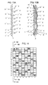
- FIG. 1 is a design diagram of a fabric of Example 1 of the present invention.
- FIGS. 2A and 2B include cross-sectional views taken along the line 2A-2A of an upper surface side warp 1 and that of a warp binding yarn 1 and a cross sectional view taken along the line 2B-2B of two warp binding yarns 2 respectively, each illustrated in the design diagram of FIG. 1.
- FIG. 3 is a plan view, viewed from the upper surface side, of a fabric woven based on the design diagram of FIG. 1.
- indicated at numeral 1 in the design diagram of FIG. 1 are both warp 1 and warp binding yarn 1, which is also applicable to numeral 6.
- Warp 2 means two warp binding yarns, which is also applicable to warp 7.
- This fabric is a 16-shaft two-layer fabric having two sets of one upper surface side warp and three warp binding yarns.
- Warps 1 and 2 constitute one set, while warps 6 and 7 constitute another one set.
- the other warps 3, 4, 5 and 8 are each a warp set composed of an upper surface side warp and a lower surface side warp.
- Upper surface side wefts and lower surface side wefts are arranged at a ratio of 2:1.
- a warp on the upper side surface, has a 1/4-1/2 design in which it passes over an upper surface side weft, passes under four successive upper surface side wefts, passes over an upper surface side weft and passes under two upper surface side wefts, while an upper surface side weft repeats a design in which it passes under an upper surface side warp or warp binding yarn and passes over three upper surface side warps and/or warp binding yarns.
- an upper surface side warp 1 repeats a 1/4-1/2 design in which it passes over an upper surface side weft 1'u, passes under four successive upper surface side wefts 2'u, 3'u, 4'u and 5'u, passes over an upper surface side weft 6'u, passes under two upper surface side wefts 7'u and 8'u, passes over an upper surface side weft 9'u, passes under four successive upper surface side wefts 10'u, 11'u, 12'u and 13'u, passes over an upper surface side weft 14'u and passes under two upper surface side wefts 15'u and 16'u.
- the design formed on the upper side surface by the three warp binding yarns which get together is also a 1/4-1/2 design.
- the warp binding yarn 1 marked with diagonal lines passes over the upper surface side weft 3'u, and then passes under the lower surface side wefts 5'd and 11'd.
- the warp binding yarn 2 in FIG. 2B with no mark has a design in which it passes under the lower surface side weft 5'd and then passes over the upper surface side wefts 8'u and 16'u.
- the warp binding yarn 2 marked with dots has a design in which it passes over the upper surface side weft 11'u and then passes under the lower surface side weft 15'd.
- a warp binding yarn passes over an upper surface weft at which the other two warp binding yarns exist under the upper surface side weft and knuckles formed by respective warp binding yarns on the upper side surface are separated from each other by two or four wefts.
- a warp binding yarn passes over an upper surface side weft, it has a force to pull down the upper surface side weft, but in the present invention, at that portion, the other two warp binding yarns pass under the upper surface side weft to support it from below so that no recess appears at the binding portion and knuckles have a uniform height.
- the upper surface side warp 1 a warp design formed by the three warp binding yarns and an upper surface side warp 3 are arranged at almost equal intervals. A description will next be made of this structure.
- the upper side knuckles of one of these warp binding yarns are indicated by • and they are formed over the upper surface side wefts 8'u and 16'u.
- the upper side knuckles of the upper surface side warp 1 which is in a row adjacent to the warp binding yarns are indicated by X and they are formed over the upper surface side wefts 1'u, 6'u, 9'u and 14'u.
- the knuckle • over the upper surface side weft 8'u acts repulsively with the contiguous knuckle X of the upper surface side warp 1 over the upper surface side weft 9'u, and tends to move in the right direction.
- the knuckle over the upper surface side weft 16'u also tends to move in the right direction, affected by the contiguous knuckle of the upper surface side warp 1 over the upper surface side weft 1'u.
- An upper side knuckle ⁇ of the other warp binding yarn 2 is also formed over the upper surface side weft 11'u.
- Upper surface side knuckles of the upper surface side warp 3 which exists in an adjacent row are indicated by X and they are formed over the upper surface side wefts 2'u, 5'u, 10'u and 13'u.
- the knuckle ⁇ over the upper surface side weft 11'u therefore acts repulsively with the contiguous knuckle of the upper surface side warp 3 over the upper surface side weft 10'u and tends to move in the left direction.
- these two warp binding yarns get together almost at the center of the upper surface side warp 1 and upper surface side warp 3, whereby the knuckles lie on a substantially a straight line.
- the warp binding yarn 1 which is adjacent to the warp binding yarns 2, forms a knuckle over the upper surface side weft 3'u. Since two warp binding yarns 2 do not form an upper side knuckle between the upper surface side wefts 1'u and 7'u so that a space exists on the upper surface side. The warp binding yarn 1 tends to move toward the warp binding yarns 2 in order to fill the space. A knuckle formed, over the upper surface side weft 4'u, by an upper surface side warp 8 which exists in a row adjacent to the warp binding yarn 1 has also an influence on this movement.
- a knuckle • over the upper surface side weft 3'u acts repulsively with the contiguous knuckle of the upper surface side warp 8 over the upper surface side weft 4'u and tends to move in the right direction.
- the knuckle of the warp binding yarn 1 seems to be taken in two warp binding yarns 2, whereby the knuckle seems to be formed on a straight line of a warp by these three warp binding yarns.
- these three warp binding yarns like three upper surface side warps, are arranged at equal intervals. This also applies to other combinations of one upper surface side warp and three warp binding yarns adjacent thereto.
- the warp binding yarn 1 and two warp binding yarns 2 repeat a 1/4-1/2 design on the upper side surface, that is, passing under two upper surface side wefts 1'u and 2'u, passing over an upper surface side weft 3'u, passing under four successive upper surface side wefts 4'u, 5'u, 6'u and 7'u, passing over an upper surface side weft 8'u, passing under two upper surface side wefts 9'u and 10'u, passing over an upper surface side weft 11'u, passing under four successive upper surface side wefts 12'u, 13'u, 14'u and 15'u, and then passing over an upper surface side weft 16'u.
- the three warp binding yarns cooperatively constitute on the upper side surface a 1/4-1/2 design similar to that of the upper surface side warp 1.
- the other two warp binding yarns lie under the upper surface side weft, which means that they lie between the upper surface side weft and a lower surface side weft or lie under the lower surface side weft so that water drainage spaces penetrating through the fabric in random oblique directions are formed, whereby the resulting fabric has an excellent water drainage property.
- a warp on the lower side passes under a lower surface side weft 5'd, passes over 7'd and 9'd, passes under 11'd and passes over 13'd, 15'd, 1'd and 3'd.
- it passes over four lower surface side wefts, passes under a lower surface side weft, passes over two lower surface side wefts and passes under a lower surface side weft, thus exhibiting a 4/1-2/1 design.
- a lower surface side weft passes over two adjacent warps on the lower side and then passes under six successive warps on the lower side to form a weft long crimp on the lower side surface.
- the fabric having excellent wear resistance can be obtained by employing a design of forming a weft long crimp on the lower side surface.
- a warp on the lower side two warp binding yarns, as a pair, form a lower surface side warp design corresponding to a warp, a warp binding yarn forms a lower surface side warp design corresponding to a warp, or a lower surface side warp forms a warp design.
- the warp binding yarn 1 of FIG. 1 is woven with a lower surface side weft to form a design corresponding to a lower surface side warp on the lower surface side.
- Two warp binding yarns 2 alternately pass under lower surface side wefts to form a design corresponding to a lower surface side warp.
- a lower surface side warp 3 is woven with a lower surface side weft to form a design corresponding to a lower surface side warp. In such a manner, long crimps of the lower surface side weft equal in length can be formed on the lower side surface.
- Lower surface side wefts are woven from the lower side by two adjacent warps so that the resulting fabric has improved rigidity.
- a wear-resistant volume increases due to the protrusion of a long crimp on the lower side surface so that the resulting fabric has excellent wear resistance.
- a zigzag arrangement in which at a portion where a warp constituting the lower side surface weaves therein a lower surface side weft from the lower side, it alternately approaches warps which are adjacent to each other on right and left sides is employed so that warps travel while winding their way to the left and right and the resulting fabric has improved rigidity in the diagonal direction.
- a lower surface side warp 4 together with a lower surface side warp 5 which is on the right adjacent thereto, forms a knuckle under the lower surface side weft 3'd and then, together with a lower surface side warp 3 which is on the left adjacent to the lower surface side warp 4, forms a knuckle under the lower surface side weft 9'd.
- the lower surface side warp 4 then moves to the right side at the intersection with the lower surface side weft 3'd and moves to the left side at the intersection with the lower surface side weft 9'd.
- it has zigzag arrangement.
- Neither upper surface side warps nor warp binding yarns employ a design of zigzag arrangement different from the warps on the lower surface side.
- Warps on the upper side and warps on the lower side overlap at some portions but do not overlap at some portions. Dehydration holes penetrating through the fabric from the upper side to the lower side therefore do not have a uniform shape, making it possible to prevent drastic dehydration.
- the lower surface side warp 4 was so far described, but the other lower surface side warps and warp binding yarns have a similar random structure, which makes it possible to obtain a fabric having, as a whole, a uniform surface property.
- FIG. 4 is a design diagram of a fabric of Example 2 according to the present invention.
- FIGS. 5A and 5B include cross-sectional views of an upper surface side warp 1 and that of a warp binding yarn 1 and two warp binding yarns 2, each illustrated in the design diagram of FIG. 4, and these three warp binding yarns get together and form a design corresponding to a warp on the upper side surface.
- indicated at numerals 1 and 5 are pairs of an upper surface side warp and a warp binding yarn
- indicated at numerals 2 and 6 are pairs of two warp binding yarns
- indicated at numerals 3, 4, 7 and 8 are pairs of an upper surface side warp and a lower surface side warp.
- the upper side surface is composed of warps having a 1/4-1/2 design and wefts having a 1/3 design, as in Example 1.
- Each of the warp binding yarn 1 and two warp binding yarns 2 does not constitute a 1/4-1/2 design on the upper side surface, but they get together and cooperatively form a 1/4-1/2 design similar to that of the upper surface side warp 1 on the upper side surface.
- the upper side surface design and lower side surface design are similar to those of Example 1, but the design of warp binding yarns constituting them is different.
- a warp binding yarn passes over an upper surface side weft, it tends to pull the upper surface side weft downward.
- another warp binding yarn passes under the upper surface side weft to support the upper surface side weft from the lower side so that no recess appears at a binding portion and the knuckles have a uniform height.
- a warp binding yarn passes over an upper surface side weft, the other two warp binding yarns lie under the upper surface side weft, which means that they lie between the upper surface side weft and a lower surface side weft or lie under the lower surface side weft so that water drainage spaces penetrating through the fiber in random oblique directions are formed, whereby the resulting fabric has an excellent water drainage property.
- a warp binding yarn is a longitudinal direction yarn onto which a tension is applied so that it has an excellent binding power. Since no additional binding yarn exists, the upper side surface design becomes uniform without being disturbed by it.
- a lower surface side weft has a design in which it passes over two adjacent warps on the lower surface side and passes under six successive warps on the lower surface side to form a weft long crimp on the lower side surface.
- Rigidity in the diagonal direction is improved owing to the zigzag arrangement employed for lower surface side warps.
- Both an overlap portion and a non-overlap portion appear between warps on the upper surface side and warps on the lower surface side.
- Meshes with a random size or shape are therefore formed so that stepwise dehydration can be carried out. This makes it possible to prevent generation of dehydration marks, sticking of a sheet raw material onto a wire or loss of fiber or filler from the wire.
- FIG. 6 is a design diagram of a fabric of Example 3 according to the present invention.
- FIGS. 7A and 7B include cross-sectional views of an upper surface side warp 1 and that of a warp binding yarn 1 and two warp binding yarns 2, each illustrated in the design diagram of FIG. 6. These three warp binding yarns get together and form a design corresponding to a warp on the upper side surface.
- indicated at numerals 1 and 5 are pairs of an upper surface side warp and a warp binding yarn
- indicated at numerals 2 and 6 are pairs of two warp binding yarns
- indicated at numerals 3, 4, 7 and 8 are pairs of an upper surface side warp and a lower surface side warp.
- the upper side surface is composed of warps having a 1/4-1/2 design and wefts having a 1/3 design, as in Example 1.
- Each of the warp binding yarn 1 and two warp binding yarns 2 does not constitute a 1/4-1/2 design on the upper side surface, but they get together and cooperatively form a 1/4-1/2 design similar to that of the upper surface side warp 1 on the upper side surface.
- the fabric of this Example is similar to that of Example 1 or 2 in the upper side surface design, but different in the lower side surface design.
- a warp binding yarn passes over an upper surface side weft, it tends to pull the upper surface side weft downward.
- another warp binding yarn passes under the upper surface side weft to support the upper surface side from the lower side so that no recess appears at the binding portion and the knuckles have a uniform height.
- a warp binding yarn passes over an upper surface side weft, the other two warp binding yarns lie under the upper surface side weft, which means that they lie between the upper surface side weft and a lower surface side weft or lie under the lower surface side weft so that water drainage spaces penetrating through the fabric in random oblique directions are formed, whereby the resulting fabric has an excellent water drainage property.
- a warp binding yarn is a longitudinal direction yarn onto which a tension is applied so that it has an excellent binding power. Since no additional binding yarn exists, the upper side surface design becomes uniform without being disturbed by it.
- a lower surface side warp passes under a lower surface side weft and then passes over three successive lower surface side wefts.
- a lower surface side weft passes over a warp on the lower surface side, passes under three successive warps on the lower surface side, passes over a warp on the lower surface side and then passes under three successive warps on the lower surface side, thereby forming a weft long crimp on the lower side surface.
- the design on the lower side surface has therefore excellent wear resistance.
- FIG. 8 is a design diagram of a fabric of Example 4 according to the present invention.
- FIGS. 9A and 9B include cross-sectional views of an upper surface side warp 1 and that of a warp binding yarn 1 and two warp binding yarns 2, each illustrated in the design diagram of FIG. 8. These three warp binding yarns get together and form a design corresponding to a warp on the upper side surface.
- warps 1 and 8 are pairs of an upper surface side warp and a warp binding yarn
- indicated at numerals 2 and 6 are pairs of two warp binding yarns
- indicated at numerals 3, 4, 7 and 8 are pairs of an upper surface side warp and a lower surface side warp.
- warps 1 to 8 each includes two yarns.
- warps form a plain weave design in which a warp alternately passes over and under upper surface side wefts.
- Each of the warp binding yarn 1 and two warp binding yarns 2 does not constitute a plain weave design on the upper side surface, but they get together and cooperatively form a 1/1 design similar to that of the upper surface side warp 1 on the upper side surface.
- a warp binding yarn passes over an upper surface side weft, it tends to pull the upper surface side weft downward.
- another warp binding yarn passes under the upper surface side weft to support the upper surface side from the lower side so that no recess appears at the binding portion and the knuckles have a uniform height.
- a warp binding yarn passes over an upper surface side weft, the other two warp binding yarns lie under the upper surface side weft, which means that they lie between the upper surface side weft and a lower surface side weft or lie under the lower surface side weft so that water drainage spaces penetrating through the fabric in random oblique directions are formed, whereby the resulting fabric has an excellent water drainage property.
- a warp binding yarn is a longitudinal direction yarn onto which a tension is applied so that it has an excellent binding power. Since no additional binding yarn exists, the upper side surface design becomes uniform without being disturbed by it.
- Example 1 On the lower side surface, a 4/1-2/1 design is formed as in Example 1.
- a lower surface side weft passes over two adjacent warps on the lower surface side and then passes under six successive warps on the lower surface side to form a weft long crimp on the lower side surface.
- Lower surface side warps are arranged in a zigzag manner so that rigidity in the diagonal direction is improved. Owing to existence of both an overlap portion and a non-overlap portion between a warp on the upper surface side and a warp on the lower surface side, meshes with a random size or shape can be formed, which enables stepwise dehydration. This makes it possible to prevent generation of dehydration marks, sticking of a sheet raw material onto a wire or loss of fiber or filler from the wire.
- FIG. 10 is a design diagram of a fabric of Example 5 according to the present invention.
- FIGS. 11A and 11B include cross-sectional views of an upper surface side warp 1 and that of a warp binding yarn 1 and two warp binding yarns 2, each illustrated in the design diagram of FIG. 10. These three warp binding yarns get together and form a design corresponding to a warp on the upper side surface.
- warps 1 and 5 are pairs of an upper surface side warp and a warp binding yarn
- indicated at numerals 2 and 6 are pairs of two warp binding yarns
- indicated at numerals 3, 4, 7 and 8 are warp pairs of an upper surface side warp and a lower surface side warp.
- warps 1 to 8 each includes two yarns.
- a plain weave design in which a warp alternately passes over and under upper surface side wefts is formed as in Example 4.
- Each of the warp binding yarn 1 and two warp binding yarns 2 does not constitute a plain weave design on the upper side surface, but they get together and cooperatively form a 1/1 design similar to that of the upper surface side warp 1 on the upper side surface.
- a warp binding yarn passes over an upper surface side weft, it tends to pull the upper surface side weft downward.
- another warp binding yarn passes under the upper surface side weft to support the upper surface side weft from the lower side so that no recess appears at the binding portion and the knuckles have a uniform height.
- a warp binding yarn passes over an upper surface side weft, the other two warp binding yarns lie under the upper surface side weft, which means that they lie between the upper surface side weft and a lower surface side weft or lie under the lower surface side weft so that water drainage spaces penetrating through the fabric in random oblique directions are formed, whereby the resulting fabric has an excellent water drainage property.
- a warp binding yarn is a longitudinal direction yarn onto which a tension is applied so that it has an excellent binding power. Since no additional binding yarn exists, the upper side surface design becomes uniform without being disturbed by it.
- a lower surface side warp passes under a lower surface side weft and then passes over three successive lower surface side wefts and this design is repeated.
- Two lower surface side warps which are adjacent to each other form the same design while passing over and under lower surface side wefts in a similar manner.
- a lower surface side weft passes over two warps on the lower surface side and then passes under six successive warps on the lower surface side to form a weft long crimp on the lower side surface.
- the design thus formed has excellent wear resistance.
- FIG. 12 is a design diagram of a fabric of Example 6 according to the present invention.
- FIGS. 13A and 13B include cross-sectional views of an upper surface side warp 1 and that of a warp binding yarn 1 and two warp binding yarns 2, each illustrated in the design diagram of FIG. 12. These three warp binding yarns get together and form a design corresponding to a warp on the upper side surface.
- warps 1 and 8 are pairs of an upper surface side warp and a warp binding yarn
- indicated at numerals 2 and 6 are pairs of two warp binding yarns
- indicated at numerals 3, 4, 7 and 8 are pairs of an upper surface side warp and a lower surface side warp.
- warps 1 to 8 each includes two yarns.
- a 2/2 design in which a warp passes over two upper surface side wefts and then passes under two upper surface side wefts is formed.
- Each of the warp binding yarn 1 and two warp binding yarns 2 does not constitute a 2/2 design on the upper side surface, but they get together and cooperatively form a 2/2 design similar to that of the upper surface side warp 1 on the upper side surface.
- a warp binding yarn passes over an upper surface side weft, it tends to pull the upper surface side weft downward.
- another warp binding yarn passes under the upper surface side weft to support the upper surface side weft from the lower side so that no recess appears at the binding portion and the knuckles have a uniform height.
- a warp binding yarn passes over an upper surface side weft, the other two warp binding yarns lie under the upper surface side weft, which means that they lie between the upper surface side weft and a lower surface side weft or lie under the lower surface side weft so that water drainage spaces penetrating through the fabric in random oblique directions are formed, whereby the resulting fabric has an excellent water drainage property.
- a warp binding yarn is a longitudinal direction yarn onto which a tension is applied so that it has an excellent binding power. Since no additional binding yarn exists, the upper side surface design becomes uniform without being disturbed by it.
- Example 2 On the lower side surface, a 4/1-2/1 design similar to that of Example 1 is formed.
- a lower surface side weft passes over two adjacent warps on the lower surface side and passes under six successive warps on the lower surface side to form a weft long crimp on the lower side surface.
- Rigidity in the diagonal direction is improved owing to the employment of zigzag arrangement for lower surface side warps.
- Both an overlap portion and a non-overlap portion appear between warps on the upper surface side and warp on the lower surface side.
- Meshes with a random size or shape are therefore formed so that stepwise dehydration can be carried out. This makes it possible to prevent generation of dehydration marks, sticking of a sheet raw material onto a wire or loss of fiber or filler from the wire.
- FIG. 14 is a design diagram of a fabric of Example 7 according to the present invention.
- FIGS. 15A and 15B include cross-sectional views of an upper surface side warp 1 and that of a warp binding yarn 1 and two warp binding yarns 2, each illustrated in the design diagram of FIG. 14. These three warp binding yarns get together and form a design corresponding to a warp on the upper side surface.
- warps 1 and 5 are pairs of an upper surface side warp and a warp binding yarn
- indicated at numerals 2 and 6 are pairs of two warp binding yarns
- indicated at numerals 3, 4, 7 and 8 are warp pairs of an upper surface side warp and a lower surface side warp.
- warps 1 to 8 each includes two yarns.
- a sateen weave design obtained by irregularly changing a 1/3 design in which a warp passes over an upper surface side weft and under three upper surface side wefts is formed.
- Each of the warp binding yarn 1 and two warp binding yarns 2 does not constitute a 1/3 design on the upper side surface, but they get together and cooperatively form a 1/3 design similar to that of the upper surface side warp 1 on the upper side surface.
- a warp binding yarn passes over an upper surface side weft, it tends to pull the upper surface side weft downward.
- another warp binding yarn passes under the upper surface side weft to support the upper surface side from the lower side so that no recess appears at the binding portion and the knuckles have a uniform height.
- a warp binding yarn passes over an upper surface side weft, the other two warp binding yarns lie under the upper surface side weft, which means that they lie between the upper surface side weft and a lower surface side weft or lie under the lower surface side weft so that water drainage spaces penetrating through the fabric in random oblique directions are formed, whereby the resulting fabric has an excellent water drainage property.
- a warp binding yarn is a longitudinal direction yarn onto which a tension is applied so that it has an excellent binding power. Since no additional binding yarn exists, the upper side surface design becomes uniform without being disturbed by it.
- a lower surface side weft has a design of passing over two adjacent warps on the lower surface side and passes under six successive warps on the lower surface side to form a weft long crimp on the lower surface side surface.
- Rigidity in the diagonal direction is improved owing to the employment of zigzag arrangement for lower surface side warps.
- Both an overlap portion and a non-overlap portion appear between warps on the upper surface side and warps on the lower surface side.
- Meshes with a random size or shape are therefore formed so that stepwise dehydration can be carried out. This makes it possible to prevent generation of dehydration marks, sticking of a sheet raw material onto a wire or loss of fiber or filler from the wire.
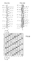
- FIG. 16 is a design diagram of a fabric of Example 8 according to the present invention.
- FIGS. 17A and 17B include cross-sectional views of an upper surface side warp 1 and that of a warp binding yarn 1 and two warp binding yarns 2, each illustrated in the design diagram of FIG. 16. These three warp binding yarns get together and form a design corresponding to a warp on the upper side surface.
- the fabrics of Examples 1 to 7 are each a 16-shaft one, but the fabric of this example is a 20-shaft one.
- a plain weave design in which a warp alternately passes over and under upper surface side wefts is formed.
- Each of the warp binding yarn 1 and two warp binding yarns 2 does not constitute a plain weave design on the upper side surface, but these three yarns get together to constitute a 1/1 design similar to that of the upper surface side warp 1.
- a warp binding yarn passes over an upper surface side weft, it tends to pull the upper surface side weft downward.
- another warp binding yarn passes under the upper surface side weft to support the upper surface side from the lower side so that no recess appears at the binding portion and the knuckles have a uniform height.
- a warp binding yarn passes over an upper surface side weft, the other two warp binding yarns lie under the upper surface side weft, which means that they lie between the upper surface side weft and a lower surface side weft or lie under the lower surface side weft so that water drainage spaces penetrating through the fabric in random oblique directions are formed, whereby the resulting fabric has an excellent water drainage property.
- a warp binding yarn is a longitudinal direction yarn onto which a tension is applied so that it has an excellent binding power. Since no additional binding yarn exists, the upper side surface design becomes uniform without being disturbed by it.
- a design of passing under a lower surface side weft and then passing over four successive lower surface side wefts is formed on the lower side surface.
- a lower surface side weft passes over a warp on the lower surface side, passes under four successive warps on the lower surface side, and then passes over a warp on the lower surface side to form a weft long crimp on the lower side surface.
- the design thus obtained has excellent wear resistance.
- FIG. 18 is a design diagram of a fabric of Example 9 according to the present invention.
- FIGS. 19A and 19B include cross-sectional views of an upper surface side warp 1 and that of a warp binding yarn 1 and two warp binding yarns 2, each illustrated in the design diagram of FIG. 18. These three warp binding yarns get together and form a design corresponding to a warp on the upper side surface.
- the fabric of this Example is a 20-shaft one similar to that of Example 8.
- warps 1 to 10 each includes two yarns.
- a plain weave design in which a warp alternately passes over and under upper surface side wefts is formed.
- Each of the warp binding yarn 1 and two warp binding yarns 2 does not constitute a plain weave design on the upper side surface, but they get together and cooperatively form, on the upper side surface, a 1/1 design similar to that of the upper surface side warp 1.
- a warp binding yarn passes over an upper surface side weft, it tends to pull the upper surface side weft downward.
- another warp binding yarn passes under the upper surface side weft to support the upper surface side from the lower side so that no recess appears at the binding portion and the knuckles have a uniform height.
- a warp binding yarn is a longitudinal direction yarn onto which a tension is applied so that it has an excellent binding power. Since no additional binding yarn exists, the upper side surface design becomes uniform without being disturbed by it.
- a lower surface side weft has a design of passing over two adjacent warps on the lower surface side and passes under eight successive warps on the lower surface side to form a weft long crimp on the lower side surface.
- Rigidity in the diagonal direction is improved owing to the employment of zigzag arrangement for lower surface side warps.
- Both an overlap portion and a non-overlap portion appear between warps on the upper surface side and warps on the lower surface side.
- Meshes with a random size or shape are therefore formed so that stepwise dehydration can be carried out. This makes it possible to prevent generation of dehydration marks, sticking of a sheet raw material onto a wire or loss of fiber or filler from the wire.
- FIG. 20 is a design diagram of a fabric of Example 10 according to the present invention.
- FIGS. 21A and 21B include cross-sectional views of an upper surface side warp 1 and that of a warp binding yarn 1 and two warp binding yarns 2, each illustrated in the design diagram of FIG. 20. These three warp binding yarns get together and form a design corresponding to a warp on the upper side surface.
- the fabric in this Example is a 20-shaft one similar to that of Example 8, 9.
- warps 1 and 6 are pairs of an upper surface side warp and a warp binding yarn
- indicated at numerals 2 and 7 are pairs of two warp binding yarns
- indicated at numerals 3, 4, 5, 8, 9 and 10 are warp pairs having an upper surface side warp and a lower surface side warp arranged vertically below the upper surface side warp.
- warps 1 to 10 each includes two yarns.
- a 2/3 design in which a warp passes over two upper surface side wefts and then passes under three upper surface side wefts is formed.
- Each of the warp binding yarn 1 and two warp binding yarns 2 does not constitute a 2/3 design on the upper side surface, but they get together and cooperatively form a 2/3 design similar to that of the upper surface side warp 1 on the upper side surface.
- a warp binding yarn passes over an upper surface side weft, it tends to pull the upper surface side weft downward.
- another warp binding yarn passes under an upper surface side weft to support the upper surface side from the lower side so that no recess appears at the binding portion and the knuckles have a uniform height.
- a warp binding yarn passes over an upper surface side weft, the other two warp binding yarns lie under the upper surface side weft, which means that they lie between the upper surface side weft and a lower surface side weft or lie under the lower surface side weft so that water drainage spaces penetrating through the fabric in random oblique directions are formed, whereby the resulting fabric has an excellent water drainage property.
- a warp binding yarn is a longitudinal direction yarn onto which a tension is applied so that it has an excellent binding power. Since no additional binding yarn exists, the upper side surface design becomes uniform without being disturbed by it.
- a lower surface side weft has a design of passing over two adjacent warps on the lower surface side and passes under eight successive warps on the lower surface side to form a weft long crimp on the lower side surface.
- Rigidity in the diagonal direction is improved owing to the employment of zigzag arrangement for lower surface side warps.
- Both an overlap portion and a non-overlap portion appear between warps on the upper surface side and warp on the lower surface side.
- Meshes with a random size or shape are therefore formed so that stepwise dehydration can be carried out. This makes it possible to prevent generation of dehydration marks, sticking of a sheet raw material onto a wire or loss of fiber or filler from the wire.
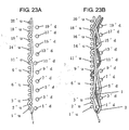
- FIG. 22 is a design diagram of a fabric of Example 11 according to the present invention.
- FIGS. 23A and 23B include cross-sectional views of an upper surface side warp 1 and that of a warp binding yarn 1 and two warp binding yarns 2, each illustrated in the design diagram of FIG. 22. These three warp binding yarns get together and form a design corresponding to a warp on the upper side surface.
- the fabric of this example is a 20-shaft one similar to that of Example 8, 9, 10.
- warps 1 and 6 are pairs of an upper surface side warp and a warp binding yarn
- indicated at numerals 2 and 7 are pairs of two warp binding yarns
- indicated at numerals 3, 4, 5, 8, 9 and 10 are warp pairs having an upper surface side warp and a lower surface side warp arranged vertically below the upper surface side warp.
- warps 1 to 10 each includes two yarns.
- each of the warp binding yarn 1 and two warp binding yarns 2 does not constitute a 1/4 weave design on the upper side surface, but they get together and cooperatively form a 1/4 design similar to that of the upper surface side warp 1 on the upper side surface.
- a warp binding yarn passes over an upper surface side weft, it tends to pull the upper surface side weft downward.
- another warp binding yarn passes under an upper surface side weft to support the upper surface side from the lower side so that no recess appears at the binding portion and the knuckles have a uniform height.
- a warp binding yarn passes over an upper surface side weft, the other two warp binding yarns lie under the upper surface side weft, which means that they lie between the upper surface side weft and a lower surface side weft or lie under the lower surface side weft so that water drainage spaces penetrating through the fabric in random oblique directions are formed, whereby the resulting fabric has an excellent water drainage property.
- a warp binding yarn is a longitudinal direction yarn onto which a tension is applied so that it has an excellent binding power. Since no additional binding yarn exists, the upper side surface design becomes uniform without being disturbed by it.
- a design of passing under a lower surface side weft and then passing over four successive lower surface side wefts is formed on the lower side surface.
- a lower surface side weft passes over a warp on the lower surface side, passes under four successive warps on the lower surface side, passes over a warp on the lower surface side and then passes under four successive warps on the lower surface side to form a weft long crimp on the lower side surface.
- the design thus obtained has excellent wear resistance.
- the fabric of embodiments of the present invention hardly transfers its wire marks to paper, has excellent breathability, water drainage property, rigidity and wear resistance, and can keep conditions necessary for the manufacture of good quality paper for a prolonged period of time until the end of its life span.
Abstract
Description
- The present invention relates to an industrial two-layer fabric.
- Fabrics woven with warps and wefts have conventionally been used widely as an industrial fabric. They are used in various fields including papermaking wires, conveyor belts and filter cloths and required to have fabric properties suited for the intended use or using environment. Of such fabrics, a papermaking wire used in a papermaking step for removing water from raw materials by making use of the meshes of a fabric must satisfy severe requirements. There is therefore a demand for the development of fabrics which hardly transfer their wire marks to paper and therefore have an excellent surface property, have a dehydration property for sufficiently removing unnecessary water contained in the raw materials, have enough wear resistance and rigidity to permit desirable use even under severe environments, and are capable of maintaining conditions necessary for making good-quality paper for a long period of time. In addition, fiber supporting property, improvement in a papermaking yield, dimensional stability and running stability are required. In recent years, owing to the speed-up of a papermaking machine, requirements for papermaking wires become severe further.
- Since most of the requirements for industrial fabrics and how to satisfy them can be understood by describing a papermaking fabric on which the most strict requirement is imposed among industrial fabrics, the present invention will hereinafter be described using the papermaking fabric as a representative example.
- For papermaking fabrics, excellent surface property not permitting transfer of wire marks of the fabric to paper, dehydration property for sufficiently removing unnecessary water contained in the raw materials, fiber supporting property for supporting fine fibers, and rigidity permitting long-period running even under severe running conditions are very important. Research on the design or constitution of a fabric capable of satisfying the above-described properties is proceeding. Recently, two-layer fabrics using a warp binding yarn which functions as an upper surface side warp or lower surface side warp are known. The warp binding yarn has a binding function for weaving both an upper surface side weft and a lower surface side weft. At the same time, it has a function similar to that of an upper surface side warp or lower surface side warp constituting a portion of the upper side surface or lower side surface.
- A two-layer fabric using a warp binding yarn is disclosed in
Japanese Patent Laid-Open No. 2003-342889 - Thus, fabrics capable of satisfying all the properties that an industrial fabric is required to have such as dehydration property, surface property and rigidity have not yet been developed.
- Various respective aspects and features of the invention are defined in the appended claims. Features from the dependent claims may be combined with features of the independent claims as appropriate and not merely as explicitly set out in the claims.
- An embodiment of the present invention provides an industrial two-layer fabric capable of satisfying all the properties that an industrial fabric must have such as dehydration property, surface property and rigidity. layer fabric having an upper side layer and a lower side layer. The upper side layer is comprised of an upper surface side warp that forms a warp design on an upper side surface and an upper surface side weft. The upper side layer is further comprised of a warp binding yarn for weaving an upper surface side weft and a lower surface side weft to bind the upper layer and the lower layer. The lower side layer is comprised of a lower surface side warp, a lower surface side weft and the warp binding yarn.
- In a repeating unit of the industrial two-layer fabric, one upper surface side warp is disposed adjacent to three warp binding yarns each of which has a binding yarn design of passing over one or two successive upper surface side wefts to form a knuckle on the upper side surface. The three warp binding yarns appear on the upper side surface in turn, pass over respectively different upper surface side wefts, and form, on the upper side surface, knuckles between which at least one upper surface side weft exists. The three warp binding yarns get together and form, adjacent to the upper surface side warp, the warp design on the upper side surface.
- At a portion in which one of the three warp binding yarns passes over one upper surface side weft, the other two warp binding yarns may pass under at least three upper surface side wefts including the one upper surface side weft.
- In addition to the one upper surface side warp and the three warp binding yarns, one lower surface side warp that forms a warp pair with the one upper surface side warp may be arranged vertically below the one upper surface side warp. The three warp binding yarns may have the same design or different designs respectively.
- The three warp binding yarns get together and form the warp design on the upper side surface, and may form on the upper side surface, woven together with the upper surface side warp and upper surface side weft, any one of a plain weave design, a twill weave design, a sateen weave design, a 1/4-1/2 design in which a warp passes over an upper surface side weft, passes under four successive upper surface side wefts, passes over an upper surface side weft and passes under two successive upper surface side wefts, or a 2/2 design in which a warp passes over two upper surface side wefts and passes under two upper surface side wefts.
- The lower surface side weft may pass over two successive lower surface side warps and/or warp binding yarns and then pass under at least two successive lower surface side warps and/or warp binding yarns in the repeating unit. The lower surface side weft may pass over one lower surface side warp or warp binding yarn and then passes under at least two successive lower surface side warps and/or warp binding yarns.
- The term such as "plain weave design" which is conventionally used for describing the design of a fabric means not only the design of a fabric but also the design of a yarn. For example, a warp which is woven with wefts and repeats a design of passing over a weft and then passing under a weft adjacent thereto is regarded to have a plain weave design.
- The industrial two-layer fabric of embodiments of the present invention invention has one upper surface side warp and three warp binding yarns adjacent thereto which get together to form on the upper side surface a design corresponding to a warp. Since the design and knuckle height of the fabric is uniform, the fabric has an excellent surface property. In addition, owing to existence of many spaces in the diagonal direction in the fabric layer compared with the conventional fabric, it has excellent breathability and water drainage property, fabric rigidity and surface property.
- The invention will now be described by way of example with reference to the accompanying drawings, throughout which like parts are referred to by like references, and in which:
- FIG. 1 is a design diagram of an industrial two-layer fabric of Example 1 according to the present invention.
- FIGS. 2A and 2B include cross-sectional views taken along the
line 2A-2A of a first bindingwarp pair 1 and long theline 2B-2B of a secondbinding warp pair 2 in FIG. 1 respectively. - FIG. 3 is a plan view illustrating the upper side surface of FIG. 1.
- FIG. 4 is a design diagram of an industrial two-layer fabric of Example 2 according to the present invention.
- FIGS. 5A and 5B include cross-sectional views taken along the
line 5A-5A of a first bindingwarp pair 1 and along theline 5B-5B of a secondbinding warp pair 2 in FIG. 4 respectively. - FIG. 6 is a design diagram of an industrial two-layer fabric of Example 3 according to the present invention.
- FIGS. 7A and 7B include cross-sectional views taken along the
line 7A-7A of a first bindingwarp pair 1 and along theline 7B-7B of a secondbinding warp pair 2 in FIG. 6 respectively. - FIG. 8 is a design diagram of an industrial two-layer fabric of Example 4 according to the present invention.
- FIGS. 9A and 9B include cross-sectional views taken along the
line 9A-9A of a first bindingwarp pair 1 and along theline 9B-9B of a secondbinding warp pair 2 in FIG. 8 respectively. - FIG. 10 is a design diagram of an industrial two-layer fabric of Example 5 according to the present invention.
- FIGS. 11A and 11B include cross-sectional views taken along the
line 11A-11A of a first bindingwarp pair 1 and along theline 11B-11B of a secondbinding warp pair 2 in FIG. 10 respectively. - FIG. 12 is a design diagram of an industrial two-layer fabric of Example 6 according to the present invention.
- FIGS. 13A and 13B include cross-sectional views taken along the
line 13A-13A of a first bindingwarp pair 1 and along theline 13B-13B of a secondbinding warp pair 2 in FIG. 12 respectively. - FIG. 14 is a design diagram of an industrial two-layer fabric of Example 7 according to the present invention.
- FIGS. 15A and 15B include cross-sectional views taken along the
line 15A-15A of a first bindingwarp pair 1 and along theline 15B-15B of a secondbinding warp pair 2 in FIG. 14 respectively. - FIG. 16 is a design diagram of an industrial two-layer fabric of Example 8 according to the present invention.
- FIGS. 17A and 17B include cross-sectional views taken along the
line 17A-17A of a firstbinding warp pair 1 and along theline 17B-17B of a secondbinding warp pair 2 in FIG. 16 respectively. - FIG. 18 is a design diagram of an industrial two-layer fabric of Example 9 according to the present invention.
- FIGS. 19A and 19B include cross-sectional views taken along the
line 19A-19A of a firstbinding warp pair 1 and along theline 19B-19B of a secondbinding warp pair 2 in FIG. 18 respectively. - FIG. 20 is a design diagram of an industrial two-layer fabric of Example 10 according to the present invention.
- FIGS. 21A and 21B include cross-sectional views taken along the
line 21A-21A of a firstbinding warp pair 1 and along theline 21B-21B of a secondbinding warp pair 2 in FIG. 20 respectively. - FIG. 22 is a design diagram of an industrial two-layer fabric of Example 11 according to the present invention.
- FIGS. 23A and 23B include cross-sectional views taken along the
line 23A-23A of a firstbinding warp pair 1 and along theline 23B-23B of a secondbinding warp pair 2 in FIG. 22 respectively. - In the drawings,
numerals - The industrial two-layer fabric of embodiments of the present invention has an upper surface side layer and a lower surface side layer. The upper surface side layer is composed of a warp binding yarn to be woven with both an upper surface side weft and a lower surface side weft to bind the upper and lower layers, an upper surface side warp and an upper surface side weft. The lower layer, on the other hand, is composed of a warp binding yarn, a lower surface side warp and a lower surface side weft. One upper surface side warp is disposed adjacent to three warp binding yarns. The warp binding yarns each has a design of passing over one or two successive upper surface side wefts to form a knuckle on the upper surface side. In addition, the three warp binding yarns appear on the upper side surface in turn; pass over respectively different upper surface side wefts; form knuckles on the upper side surface between which at least one upper surface side weft exists; and adjacent to the one upper surface side warp, get together to form on the upper surface side a design corresponding to a warp.
- The term "three warp binding yarns get together" as used herein means that warps must usually be disposed at equal intervals, but owing to the action of a force attributable to the design, knuckles formed over upper surface side wefts by three warp binding yarns lie on a substantially a straight line. The action of this force will be described later in Examples.
- The fabric of embodiments of the present invention is a two-layer fabric using warp binding yarns. Since a longitudinal direction yarn (direction upon use of the fabric) is used for binding, the fabric is always used under tension and is therefore free from occurrence of internal wear which will otherwise be caused by loosening of upper and lower layers. Compared with an additional binding yarn used only for binding, the warp binding yarns serve as a warp forming a surface and do not generate additional marks. In addition, since no additional binding yarn is used, the shooting number can be increased. The fabric has therefore an excellent fiber supporting property.
- In the conventional fabrics, a space inside thereof is blocked by two adjacent warp binding yarns crossing each other and their breathability and water drainage property are insufficient. In the fabric of the present invention, on the other hand, three warp binding yarns appear on the upper side surface in turn and when a warp binding yarn passes over an upper surface side weft, the other two warp binding yarns exist between the upper surface side weft and a lower surface side weft or under the lower surface side weft. Owing to diagonal spaces which have appeared among these three warp binding yarns, the fabric has an excellent water drainage property and breathability.
- The term "knuckle" as used herein means a winded and protruded portion formed on the upper side surface or lower side surface by passing of an upper surface side warp, a warp binding yarn or a lower surface side warp over or under one or two wefts to interweave therewith and it is formed over an upper surface side weft in the upper surface side layer and under a lower surface side weft in the lower surface side layer. An upper surface side warp is woven with an upper surface side weft to form an upper side surface design. A warp binding yarn is woven with both an upper surface side weft and a lower surface side weft to constitute a portion of the upper side surface design and a portion of the lower side surface design. Three warp binding yarns which are adjacent to one another get together to form on the upper side surface a design corresponding to an upper surface side warp. The warp binding yarn also functions as a binding yarn for weaving the upper layer with the lower layers.
- The fabric of embodiments of the present invention is obtained by disposing one upper surface side warp adjacent to three warp binding yarns. In addition to these warps, a warp pair composed of an upper surface side warp to be woven with an upper surface side weft and a lower surface side warp to be woven with a lower surface side weft may be disposed. A warp binding yarn is necessary for weaving upper and lower layers and a fabric must have at least one set in its repeating unit or complete design. An increase of a proportion of warp binding yarns leads to an improvement of binding power but disposal of at least one set in a repeating unit or a complete design is sufficient. The "one set" contains one upper surface side warp and three warp binding yarns which are adjacent to each other. The term "two sets" means the above-described set and another set. When the number of the sets increases, the number of warp binding yarns increases, which leads to improvement in the binding strength of the upper and lower layers. In a 16-shaft complete design, for example, it is only necessary to dispose a set of one upper surface side warp and three warp binding yarns and, as the remaining warps, warp pairs. In short, the fabric is composed of one set and six warp pairs. When the number of the set is increased to two, four warp pairs are disposed. When the number of the sets is three, two warp pairs are disposed. When the number of the set is four, no warp pair exists so a lower surface side warp is not disposed. It is needless to say that no limitation is imposed on the number of shafts and it can be increased to 20, 24 or the like. The set and the warp pair may also be disposed at any ratio.
- The term "shaft" means the number of heddles for lifting up and down yarns constituting a repeating unit or a complete design and the term "the number of shafts" means the number of warps constituting the complete design. For example, a two-layer fabric having a complete design formed by eight upper surface side warps and eight lower surface side warps is a 16-shaft fabric.
- In embodiments of the present invention, one upper surface side warp is disposed adjacent to three warp binding yarns. In addition to this absolute requirement, these three warp binding yarns must be adjacent to one another. For example, three warp binding yarns never have an upper surface side warp among them because these three warp binding yarns get together to form a surface design similar to that of the one upper surface side warp. For this purpose, the three warp binding yarns are required to be disposed adjacent to one another. In addition, adjacent to the three warp binding yarns, the one upper surface side warp must be disposed and the number of this upper surface side warp cannot be increased to two because of the weaving problem. The fabric of the present invention essentially has, as a warp pair, an upper surface side warp and a lower surface side warp arranged vertically below the upper surface side warp. The one upper surface side warp and three warp binding yarns adjacent thereto are substituted for two upper surface side warps and two lower surface side warps which will otherwise be disposed. A combination of three warp binding yarns alone or a combination of three warp binding yarns and two upper surface side warps cannot be substituted for two upper surface side warps and two lower surface side warps. A warp binding yarn is disposed at a position where an upper surface side warp or lower surface side warp must originally be disposed. The number of a warp binding yarn must therefore be determined depending on the number of the upper surface side warp or lower surface side warp, which is known to those skilled in the art. With regard to the one upper surface side warp and three warp binding yarns in the present invention, the upper surface side warp and one of the warp binding yarns are overlapped and illustrated as a row and the other two warp binding yarns are overlapped and illustrated as a row, each in the design diagrams of Examples which will be shown in later. They are illustrated in a similar manner to that conventionally employed for the illustration of an upper surface side warp and a lower surface side warp. Respective replacement of an upper surface side warp and a lower surface side warp with warp binding yarns facilitates understanding. In an actual fabric, however, their rows are not arranged at equal intervals. Some get together and some are separated from each other.
- Each warp binding yarn has a design of passing over one or two successive upper surface side wefts to form a knuckle on the upper side surface. The three warp binding yarns do not necessarily have the same design and they may be respectively different. In particular, they preferably have the same design or mirror-image designs which are left-right reversal each other, because their downward pulling strength of an upper surface side weft becomes constant, making it possible to form, on the surface, knuckles having a uniform height, and because tension balance between them during weaving becomes almost equal, which facilitates adjustment during weaving and eliminates the need for increasing the number of beams of a weaving machine.
- It is also preferred to employ the same design for two of the three warp binding yarns and a different design for the remaining one warp binding yarn. These three warp binding yarns are designed to appear on the upper side surface in turn and pass over respectively different upper surface side wefts.
- The three warp binding yarns get together to form a surface design similar to that of the one upper surface side warp with the proviso that at least one upper surface side weft exists between knuckles formed on the upper side surface by these three warp binding yarns. At a portion where one of the warp binding yarn passes over an upper surface side weft, the other two warp binding yarns have preferably a design of passing under at least three upper surface side wefts including the above-described upper surface side weft in order to bring the three warp binding yarns close to each other and allow them to function as one upper surface side warp. Supposing that two of the three warp binding yarns have a design of passing over two adjacent upper surface side wefts, adjacent knuckles of warp binding yarns act repulsively, are separated and do not seem to be a warp owing to the action of a force such as a pulling force or pulled force in the longitudinal direction or vertical direction caused by the upward and downward movements of warps, or a structural force caused by the upward and downward movements of wefts resulting from the above-described force of warps. When the knuckles formed by the three warp binding yarns gather in one line to show as if one upper surface side warp forms these knuckles one after another on the upper surface side warp, it is important to locate knuckles apart from each other.
- At a portion where one of the three warp binding yarns passes over an upper surface side weft, the other two exist under the upper surface side weft, more specifically, between the upper surface side weft and a lower surface side weft or under the lower surface side weft. The upper surface side weft is therefore pushed upward by them and is prevented from being pulled down at the portion where the warp binding yarn passes over the weft. This reduces a height difference between knuckles formed on the upper side surface by the warp binding yarns and knuckles formed by the upper surface side warp, whereby knuckles having a uniform height are formed on the upper side surface.
- Similarly, at the portion where one of the three warp binding yarns passes over an upper surface side weft, the other two warp binding yarns exist under the upper surface side weft, more specifically, between the upper surface side weft and a lower surface side weft or under the lower surface side weft. Water drainage spaces penetrating through the fabric in random diagonal directions are therefore formed, whereby the resulting fabric has an excellent water drainage property.
- The design of the three warp binding yarns will next be described in detail. For example, three warp binding yarns are brought close to each other to form a 1/3 design in which any one of them passes over an upper surface side weft and passes under three successive upper surface side wefts. The 1/3 design is formed, for example, by causing any one of the three warp binding yarns to pass over the 4-th, 8-th, 12-th and 16-th upper surface side wefts. Then, one of them passes over the 4-th and 12-th upper surface side wefts, one of the remaining two passes the 8-th upper surface side weft, and the last one passes over the 16-th upper surface side weft. It is needless to say that what warp binding yarn passes over what weft can be selected as needed. Since any one of these three warp binding yarns must be woven with both an upper surface side weft and a lower surface side weft, it must pass under at least one lower surface side weft at a portion where it does not pass over an upper surface side weft. Adjacent to these three warp binding yarns, one upper surface side warp lies while repeating a design of passing over an upper surface side weft and then passing under three successive upper surface side wefts.
- No particular limitation is imposed on the design formed on the upper side surface. The design is, for example, a 1/4-1/2 design in which a warp passes over an upper surface side weft, passes under four successive upper surface side wefts, passes over an upper surface side weft and passes under two upper surface side wefts. In addition, a plain weave design in which a warp alternately passes over and under wefts, a twill weave design obtained by shifting, by one weft, a 1/3 design in which a warp passes over a weft and then passes under three wefts, or a sateen weave design obtained by irregularly shifting the 1/3 design can be employed. The upper surface side warp constitutes such a design by itself so the design can be employed as is, but it is necessary to take due consideration of the design and combination of the designs of three warp binding yarns when they adopt such a design.
- No particular limitation is imposed on the lower side surface design. For example, preferred is a design in which a lower surface side weft passes over two successive lower surface side warps and/or warp binding yarns and then passes under two or more successive lower surface side warps and/or warp binding yarns to form a long crimp of the lower surface side weft on the lower side surface. In particular, at a portion of the three warp binding yarns, it is possible for two of them to alternately have a design similar to that of a lower surface side warp and for the remaining one to have a design similar to that of a lower surface side warp. Anyway, the design must be determined after consideration of the relation with the upper side surface design.
- By employing a design in which two adjacent warps on the lower surface side simultaneously weave a lower surface side weft, the long crimp of lower surface side weft protrudes more from the surface, which improves both wear resistance and at the same time improves rigidity. When a warp and a warp right-hand adjacent thereto simultaneously weave a lower surface side weft from the lower side, and then the warp and a warp left-hand adjacent thereto simultaneously weave another lower surface side weft from the lower side, the warps on the lower surface side snake their way and forms zigzag arrangement. Owing to such a design, the fabric has improved rigidity in the diagonal direction. Moreover, owing to existence of both an overlap portion and a non-overlap portion between a warp on the upper surface side and a warp on the lower surface side, meshes with a random size or shape can be formed, which enables stepwise dehydration. This makes it possible to prevent generation of dehydration marks, sticking of a sheet raw material onto a wire or loss of fiber or filler from the wire.
- Two warps on the lower surface side which are adjacent to each other may have a design of passing over and under the same upper surface side wefts to form a long crimp of a lower surface side weft.
- No particular limitation is imposed on the arrangement ratio of upper surface side wefts and lower surface side wefts. It is preferred that in the papermaking fabric, the upper side surface is made dense from the standpoints of fiber supporting property and surface property and the lower side surface is made rough because wefts having a larger diameter are preferably used in order to improve wear resistance. For example, upper surface side wefts and lower surface side wefts are arranged at a ratio of 2:1, 4:3, 3:2 or the like. They may of course be arranged at a ratio of 1:1.
- On the upper side surface, auxiliary wefts smaller in diameter than upper surface side wefts may be placed between upper surface side wefts. For example, an upper surface side weft and an auxiliary weft are arranged alternately to form a long crimp of the auxiliary weft passing over a plurality of warps. Such a design is effective for improving the fiber supporting property of wefts.
- Although no particular limitation is imposed on the diameter of constituent yarns, upper surface side wefts and upper surface side warps constituting the upper side surface preferably have a relatively smaller diameter in order to obtain a dense and smooth surface. For applications requiring a good surface property, use of warp binding yarns having an equal diameter to upper surface side warps is preferred. A difference in diameter between upper surface side warps and warp binding yarns is not preferred because yarns having a larger diameter may protrude from the upper side surface and give wire marks to paper. When upper surface side warps and warp binding yarns have an equal diameter, warp knuckles on the upper side have almost an equal height, making it possible to form a relatively uniform surface. Warp binding yarns and lower surface side warps may have the same diameter when wear resistance is an important factor.
- The lower side surface which will be brought into contact with a machine or roll requires rigidity and wear resistance so that lower surface side wefts and lower surface side warps have preferably a relatively large diameter.
- Yarns to be used in the present invention may be selected depending on the using purpose. Examples of them include, in addition to monofilaments, multifilaments, spun yarns, finished yarns subjected to crimping or bulking such as so-called textured yarn, bulky yarn and stretch yarn, and yarns obtained by intertwining them. As the cross-section of the yarn, not only circular form but also square or short form such as stellar form, or elliptical or hollow form can be used. The material of the yarn can be selected freely and usable examples of it include polyester, polyamide, polyphenylene sulfide, polyvinylidene fluoride, polypropylene, aramid, polyether ether ketone, polyethylene naphthalate, polytetrafluoroethylene, cotton, wool and metal. Of course, yarns obtained using copolymers or incorporating or mixing the above-described material with a substance selected depending on the intended purpose may be used.
- As upper surface side warps, lower surface side warps, warp binding yarns and upper surface side wefts of a paper making wire, polyester monofilaments having rigidity and excellent size stability are usually suited. As lower surface side wefts which require wear resistance, those obtained by interweaving a polyester monofilament and a polyamide filament, for example, by disposing them alternately are preferred because the fabric using such a weft has improved wear resistance while maintaining rigidity.
- Example embodiments of the present invention will next be described based on accompanying drawings. The description can also be applied to another warp row and is common in all the design diagrams.
- For convenience of the design diagrams, a
warp 1 represents an uppersurface side warp 1 and awarp binding yarn 1, and awarp 2 adjacent to thewarp 1 represents two warp binding yarns. - With regard to a warp pair, an upper surface side warp and a lower surface side warp are shown in a row.
- FIGS. 1 to 23B are design diagrams or cross-sectional views taken along warps illustrating example embodiments of the present invention. FIG. 3 is a plan view of the upper surface side of the design diagram of Example 1.
- A design diagram is a minimum repeating unit of a fabric design and a whole fabric design is formed by connecting this complete design longitudinally and latitudinally. In the design diagram, warps are indicated by Arabic numerals, for example 1, 2 and 3, of which some are pairs of warps composed of an upper surface side warp and a lower surface side warp, some are pairs of an upper surface side warp and a warp binding yarn, and some are pairs of two binding warps. Wefts are indicated by Arabic numerals with a prime, for example, 1', 2' and 3'. In particular, upper surface side wefts are indicated by attaching "u" thereto, for example, 1'u, 2'u and 3'u, while lower surface side wefts are indicated by attaching "d", for example 1'd, 2'd and 3'd. Some of the wefts have an upper surface side weft and a lower surface side weft stacked vertically and some are composed only of an upper surface side weft, which is determined depending on the arrangement ratio.
- In these diagrams, a mark "X" means that an upper surface side warp lies over an upper surface side weft; a mark "□" indicates that a lower surface side warp lies under a lower surface side weft; a mark "•" indicates that a warp binding yarn lies over an upper surface side weft; a mark "○" indicates that a warp binding yarn lies under a lower surface side weft; a mark "◆" indicates that a warp binding yarn lies over an upper surface side weft; and a mark "◇" indicates that a warp binding yarn lies under a lower surface side weft.
- In the design diagrams, yarns are vertically overlapped precisely. They are however illustrated as such for convenience of drawing and misalignment sometimes occurs in the actual fabric. With regard to wefts, some upper surface side wefts do not have a lower surface side weft thereunder because of the arrangement ratio.
- In particular, in the design diagram, a positional relationship between one upper surface side warp and three warp binding yarns is indicated by disposing a pair of an upper surface side warp and a warp binding yarn adjacent to a pair of two warp binding yarns. It cannot be understood from the design diagram that these three warp binding yarns get together, but can be understood from the cross-sectional views taken along warps and the plan view of the upper side surface.
- FIG. 1 is a design diagram of a fabric of Example 1 of the present invention. FIGS. 2A and 2B include cross-sectional views taken along the
line 2A-2A of an uppersurface side warp 1 and that of awarp binding yarn 1 and a cross sectional view taken along theline 2B-2B of twowarp binding yarns 2 respectively, each illustrated in the design diagram of FIG. 1. FIG. 3 is a plan view, viewed from the upper surface side, of a fabric woven based on the design diagram of FIG. 1. For convenience of explanation, indicated atnumeral 1 in the design diagram of FIG. 1 are bothwarp 1 and warp bindingyarn 1, which is also applicable to numeral 6.Warp 2 means two warp binding yarns, which is also applicable to warp 7. This fabric is a 16-shaft two-layer fabric having two sets of one upper surface side warp and three warp binding yarns.Warps warps other warps - In the design diagram of FIG. 1, on the upper side surface, a warp has a 1/4-1/2 design in which it passes over an upper surface side weft, passes under four successive upper surface side wefts, passes over an upper surface side weft and passes under two upper surface side wefts, while an upper surface side weft repeats a design in which it passes under an upper surface side warp or warp binding yarn and passes over three upper surface side warps and/or warp binding yarns. Described specifically, on the upper side surface, an upper
surface side warp 1 repeats a 1/4-1/2 design in which it passes over an upper surface side weft 1'u, passes under four successive upper surface side wefts 2'u, 3'u, 4'u and 5'u, passes over an upper surface side weft 6'u, passes under two upper surface side wefts 7'u and 8'u, passes over an upper surface side weft 9'u, passes under four successive upper surface side wefts 10'u, 11'u, 12'u and 13'u, passes over an upper surface side weft 14'u and passes under two upper surface side wefts 15'u and 16'u. - The design formed on the upper side surface by the three warp binding yarns which get together is also a 1/4-1/2 design. As can be understood from the cross-sectional views of FIG. 2A taken along warps, the
warp binding yarn 1 marked with diagonal lines passes over the upper surface side weft 3'u, and then passes under the lowersurface side wefts 5'd and 11'd. Thewarp binding yarn 2 in FIG. 2B with no mark has a design in which it passes under the lowersurface side weft 5'd and then passes over the upper surface side wefts 8'u and 16'u. Thewarp binding yarn 2 marked with dots has a design in which it passes over the upper surface side weft 11'u and then passes under the lower surface side weft 15'd. In any one of these three designs, a warp binding yarn passes over an upper surface weft at which the other two warp binding yarns exist under the upper surface side weft and knuckles formed by respective warp binding yarns on the upper side surface are separated from each other by two or four wefts. Thus, it is possible to put knuckles formed by three warp binding yarns on one line without causing repulsion among them by employing a design in which at least one upper surface side weft exists between two knuckles formed over the upper side surface by three warp binding yarns. As a result, an upper surface side warp seems to form knuckles one after another on the upper side surface. - At a binding portion where a warp binding yarn passes over an upper surface side weft, it has a force to pull down the upper surface side weft, but in the present invention, at that portion, the other two warp binding yarns pass under the upper surface side weft to support it from below so that no recess appears at the binding portion and knuckles have a uniform height.
- In the plan view of FIG. 3, the upper
surface side warp 1, a warp design formed by the three warp binding yarns and an uppersurface side warp 3 are arranged at almost equal intervals. A description will next be made of this structure. - First, the reason why two
warp binding yarns 2 get together will be described. The upper side knuckles of one of these warp binding yarns are indicated by • and they are formed over the upper surface side wefts 8'u and 16'u. The upper side knuckles of the uppersurface side warp 1 which is in a row adjacent to the warp binding yarns are indicated by X and they are formed over the upper surface side wefts 1'u, 6'u, 9'u and 14'u. The knuckle • over the upper surface side weft 8'u acts repulsively with the contiguous knuckle X of the uppersurface side warp 1 over the upper surface side weft 9'u, and tends to move in the right direction. Similarly, the knuckle over the upper surface side weft 16'u also tends to move in the right direction, affected by the contiguous knuckle of the uppersurface side warp 1 over the upper surface side weft 1'u. - An upper side knuckle ◆ of the other
warp binding yarn 2 is also formed over the upper surface side weft 11'u. Upper surface side knuckles of the uppersurface side warp 3 which exists in an adjacent row are indicated by X and they are formed over the upper surface side wefts 2'u, 5'u, 10'u and 13'u. The knuckle ◆ over the upper surface side weft 11'u therefore acts repulsively with the contiguous knuckle of the uppersurface side warp 3 over the upper surface side weft 10'u and tends to move in the left direction. By such tendencies, these two warp binding yarns get together almost at the center of the uppersurface side warp 1 and uppersurface side warp 3, whereby the knuckles lie on a substantially a straight line. - These two
warp binding yarns 2 and warp bindingyarn 1 get together because of the following reason. Thewarp binding yarn 1, which is adjacent to thewarp binding yarns 2, forms a knuckle over the upper surface side weft 3'u. Since twowarp binding yarns 2 do not form an upper side knuckle between the upper surface side wefts 1'u and 7'u so that a space exists on the upper surface side. Thewarp binding yarn 1 tends to move toward thewarp binding yarns 2 in order to fill the space. A knuckle formed, over the upper surface side weft 4'u, by an uppersurface side warp 8 which exists in a row adjacent to thewarp binding yarn 1 has also an influence on this movement. Similar to the above-described phenomenon, a knuckle • over the upper surface side weft 3'u acts repulsively with the contiguous knuckle of the uppersurface side warp 8 over the upper surface side weft 4'u and tends to move in the right direction. By this, the knuckle of thewarp binding yarn 1 seems to be taken in twowarp binding yarns 2, whereby the knuckle seems to be formed on a straight line of a warp by these three warp binding yarns. At the same time, these three warp binding yarns, like three upper surface side warps, are arranged at equal intervals. This also applies to other combinations of one upper surface side warp and three warp binding yarns adjacent thereto. - Thus, the
warp binding yarn 1 and twowarp binding yarns 2 repeat a 1/4-1/2 design on the upper side surface, that is, passing under two upper surface side wefts 1'u and 2'u, passing over an upper surface side weft 3'u, passing under four successive upper surface side wefts 4'u, 5'u, 6'u and 7'u, passing over an upper surface side weft 8'u, passing under two upper surface side wefts 9'u and 10'u, passing over an upper surface side weft 11'u, passing under four successive upper surface side wefts 12'u, 13'u, 14'u and 15'u, and then passing over an upper surface side weft 16'u. In short, the three warp binding yarns cooperatively constitute on the upper side surface a 1/4-1/2 design similar to that of the uppersurface side warp 1. - At a portion where one of the warp binding yarns passes over an upper surface side weft, the other two warp binding yarns lie under the upper surface side weft, which means that they lie between the upper surface side weft and a lower surface side weft or lie under the lower surface side weft so that water drainage spaces penetrating through the fabric in random oblique directions are formed, whereby the resulting fabric has an excellent water drainage property.
- As is apparent from the
warp 1 of FIG. 1, on the lower side surface, a warp on the lower side passes under a lowersurface side weft 5'd, passes over 7'd and 9'd, passes under 11'd and passes over 13'd, 15'd, 1'd and 3'd. In short, it passes over four lower surface side wefts, passes under a lower surface side weft, passes over two lower surface side wefts and passes under a lower surface side weft, thus exhibiting a 4/1-2/1 design. A lower surface side weft passes over two adjacent warps on the lower side and then passes under six successive warps on the lower side to form a weft long crimp on the lower side surface. The fabric having excellent wear resistance can be obtained by employing a design of forming a weft long crimp on the lower side surface. With regard to a warp on the lower side, two warp binding yarns, as a pair, form a lower surface side warp design corresponding to a warp, a warp binding yarn forms a lower surface side warp design corresponding to a warp, or a lower surface side warp forms a warp design. For example, thewarp binding yarn 1 of FIG. 1 is woven with a lower surface side weft to form a design corresponding to a lower surface side warp on the lower surface side. Twowarp binding yarns 2 alternately pass under lower surface side wefts to form a design corresponding to a lower surface side warp. A lowersurface side warp 3 is woven with a lower surface side weft to form a design corresponding to a lower surface side warp. In such a manner, long crimps of the lower surface side weft equal in length can be formed on the lower side surface. - Lower surface side wefts are woven from the lower side by two adjacent warps so that the resulting fabric has improved rigidity. In addition, a wear-resistant volume increases due to the protrusion of a long crimp on the lower side surface so that the resulting fabric has excellent wear resistance. Moreover, a zigzag arrangement in which at a portion where a warp constituting the lower side surface weaves therein a lower surface side weft from the lower side, it alternately approaches warps which are adjacent to each other on right and left sides is employed so that warps travel while winding their way to the left and right and the resulting fabric has improved rigidity in the diagonal direction. Owing to the existence of both an overlap portion and a non-overlap portion between a warp on the upper surface side with a warp on the lower surface side, meshes with a random size or shape can be formed and stepwise dehydration can therefore be carried out. This makes it possible to prevent generation of dehydration marks, sticking of a sheet raw material onto a wire or loss of fiber or filler from the wire.
- For example, a lower
surface side warp 4, together with a lowersurface side warp 5 which is on the right adjacent thereto, forms a knuckle under the lowersurface side weft 3'd and then, together with a lowersurface side warp 3 which is on the left adjacent to the lowersurface side warp 4, forms a knuckle under the lowersurface side weft 9'd. The lowersurface side warp 4 then moves to the right side at the intersection with the lowersurface side weft 3'd and moves to the left side at the intersection with the lowersurface side weft 9'd. Thus, it has zigzag arrangement. Neither upper surface side warps nor warp binding yarns employ a design of zigzag arrangement different from the warps on the lower surface side. Warps on the upper side and warps on the lower side overlap at some portions but do not overlap at some portions. Dehydration holes penetrating through the fabric from the upper side to the lower side therefore do not have a uniform shape, making it possible to prevent drastic dehydration. The lowersurface side warp 4 was so far described, but the other lower surface side warps and warp binding yarns have a similar random structure, which makes it possible to obtain a fabric having, as a whole, a uniform surface property. - FIG. 4 is a design diagram of a fabric of Example 2 according to the present invention. FIGS. 5A and 5B include cross-sectional views of an upper
surface side warp 1 and that of awarp binding yarn 1 and twowarp binding yarns 2, each illustrated in the design diagram of FIG. 4, and these three warp binding yarns get together and form a design corresponding to a warp on the upper side surface. In the design diagram of FIG. 4, indicated atnumerals numerals numerals - The upper side surface is composed of warps having a 1/4-1/2 design and wefts having a 1/3 design, as in Example 1. Each of the
warp binding yarn 1 and twowarp binding yarns 2 does not constitute a 1/4-1/2 design on the upper side surface, but they get together and cooperatively form a 1/4-1/2 design similar to that of the uppersurface side warp 1 on the upper side surface. The upper side surface design and lower side surface design are similar to those of Example 1, but the design of warp binding yarns constituting them is different. - At a portion where a warp binding yarn passes over an upper surface side weft, it tends to pull the upper surface side weft downward. In the present invention, however, at that portion, another warp binding yarn passes under the upper surface side weft to support the upper surface side weft from the lower side so that no recess appears at a binding portion and the knuckles have a uniform height. Moreover, at a portion where a warp binding yarn passes over an upper surface side weft, the other two warp binding yarns lie under the upper surface side weft, which means that they lie between the upper surface side weft and a lower surface side weft or lie under the lower surface side weft so that water drainage spaces penetrating through the fiber in random oblique directions are formed, whereby the resulting fabric has an excellent water drainage property. In addition, a warp binding yarn is a longitudinal direction yarn onto which a tension is applied so that it has an excellent binding power. Since no additional binding yarn exists, the upper side surface design becomes uniform without being disturbed by it.
- On the lower side surface, a 4/1-2/1 design similar to that of Example 1 is formed. A lower surface side weft has a design in which it passes over two adjacent warps on the lower surface side and passes under six successive warps on the lower surface side to form a weft long crimp on the lower side surface. Rigidity in the diagonal direction is improved owing to the zigzag arrangement employed for lower surface side warps. Both an overlap portion and a non-overlap portion appear between warps on the upper surface side and warps on the lower surface side. Meshes with a random size or shape are therefore formed so that stepwise dehydration can be carried out. This makes it possible to prevent generation of dehydration marks, sticking of a sheet raw material onto a wire or loss of fiber or filler from the wire.
- FIG. 6 is a design diagram of a fabric of Example 3 according to the present invention. FIGS. 7A and 7B include cross-sectional views of an upper
surface side warp 1 and that of awarp binding yarn 1 and twowarp binding yarns 2, each illustrated in the design diagram of FIG. 6. These three warp binding yarns get together and form a design corresponding to a warp on the upper side surface. In the design diagram of FIG. 6, indicated atnumerals numerals numerals - The upper side surface is composed of warps having a 1/4-1/2 design and wefts having a 1/3 design, as in Example 1. Each of the
warp binding yarn 1 and twowarp binding yarns 2 does not constitute a 1/4-1/2 design on the upper side surface, but they get together and cooperatively form a 1/4-1/2 design similar to that of the uppersurface side warp 1 on the upper side surface. The fabric of this Example is similar to that of Example 1 or 2 in the upper side surface design, but different in the lower side surface design. - At a portion where a warp binding yarn passes over an upper surface side weft, it tends to pull the upper surface side weft downward. In the present invention, however, at that portion, another warp binding yarn passes under the upper surface side weft to support the upper surface side from the lower side so that no recess appears at the binding portion and the knuckles have a uniform height. Moreover, at a portion where a warp binding yarn passes over an upper surface side weft, the other two warp binding yarns lie under the upper surface side weft, which means that they lie between the upper surface side weft and a lower surface side weft or lie under the lower surface side weft so that water drainage spaces penetrating through the fabric in random oblique directions are formed, whereby the resulting fabric has an excellent water drainage property. In addition, a warp binding yarn is a longitudinal direction yarn onto which a tension is applied so that it has an excellent binding power. Since no additional binding yarn exists, the upper side surface design becomes uniform without being disturbed by it.
- On the lower side surface, a lower surface side warp passes under a lower surface side weft and then passes over three successive lower surface side wefts. A lower surface side weft passes over a warp on the lower surface side, passes under three successive warps on the lower surface side, passes over a warp on the lower surface side and then passes under three successive warps on the lower surface side, thereby forming a weft long crimp on the lower side surface. The design on the lower side surface has therefore excellent wear resistance.
- FIG. 8 is a design diagram of a fabric of Example 4 according to the present invention. FIGS. 9A and 9B include cross-sectional views of an upper
surface side warp 1 and that of awarp binding yarn 1 and twowarp binding yarns 2, each illustrated in the design diagram of FIG. 8. These three warp binding yarns get together and form a design corresponding to a warp on the upper side surface. - In the design diagram of FIG. 8, indicated at
numerals numerals numerals - On the upper side surface, warps form a plain weave design in which a warp alternately passes over and under upper surface side wefts. Each of the
warp binding yarn 1 and twowarp binding yarns 2 does not constitute a plain weave design on the upper side surface, but they get together and cooperatively form a 1/1 design similar to that of the uppersurface side warp 1 on the upper side surface. - At a portion where a warp binding yarn passes over an upper surface side weft, it tends to pull the upper surface side weft downward. In the present invention, however, at this portion, another warp binding yarn passes under the upper surface side weft to support the upper surface side from the lower side so that no recess appears at the binding portion and the knuckles have a uniform height. Moreover, at a portion where a warp binding yarn passes over an upper surface side weft, the other two warp binding yarns lie under the upper surface side weft, which means that they lie between the upper surface side weft and a lower surface side weft or lie under the lower surface side weft so that water drainage spaces penetrating through the fabric in random oblique directions are formed, whereby the resulting fabric has an excellent water drainage property. In addition, a warp binding yarn is a longitudinal direction yarn onto which a tension is applied so that it has an excellent binding power. Since no additional binding yarn exists, the upper side surface design becomes uniform without being disturbed by it.
- On the lower side surface, a 4/1-2/1 design is formed as in Example 1. A lower surface side weft passes over two adjacent warps on the lower surface side and then passes under six successive warps on the lower surface side to form a weft long crimp on the lower side surface. Lower surface side warps are arranged in a zigzag manner so that rigidity in the diagonal direction is improved. Owing to existence of both an overlap portion and a non-overlap portion between a warp on the upper surface side and a warp on the lower surface side, meshes with a random size or shape can be formed, which enables stepwise dehydration. This makes it possible to prevent generation of dehydration marks, sticking of a sheet raw material onto a wire or loss of fiber or filler from the wire.
- FIG. 10 is a design diagram of a fabric of Example 5 according to the present invention. FIGS. 11A and 11B include cross-sectional views of an upper
surface side warp 1 and that of awarp binding yarn 1 and twowarp binding yarns 2, each illustrated in the design diagram of FIG. 10. These three warp binding yarns get together and form a design corresponding to a warp on the upper side surface. - In the design diagram of FIG. 10, indicated at
numerals numerals numerals - On the upper side surface, a plain weave design in which a warp alternately passes over and under upper surface side wefts is formed as in Example 4. Each of the
warp binding yarn 1 and twowarp binding yarns 2 does not constitute a plain weave design on the upper side surface, but they get together and cooperatively form a 1/1 design similar to that of the uppersurface side warp 1 on the upper side surface. - At a portion where a warp binding yarn passes over an upper surface side weft, it tends to pull the upper surface side weft downward. In the present invention, however, at that portion, another warp binding yarn passes under the upper surface side weft to support the upper surface side weft from the lower side so that no recess appears at the binding portion and the knuckles have a uniform height. Moreover, at a portion where a warp binding yarn passes over an upper surface side weft, the other two warp binding yarns lie under the upper surface side weft, which means that they lie between the upper surface side weft and a lower surface side weft or lie under the lower surface side weft so that water drainage spaces penetrating through the fabric in random oblique directions are formed, whereby the resulting fabric has an excellent water drainage property. In addition, a warp binding yarn is a longitudinal direction yarn onto which a tension is applied so that it has an excellent binding power. Since no additional binding yarn exists, the upper side surface design becomes uniform without being disturbed by it.
- On the lower side surface, a lower surface side warp passes under a lower surface side weft and then passes over three successive lower surface side wefts and this design is repeated. Two lower surface side warps which are adjacent to each other form the same design while passing over and under lower surface side wefts in a similar manner. A lower surface side weft passes over two warps on the lower surface side and then passes under six successive warps on the lower surface side to form a weft long crimp on the lower side surface. The design thus formed has excellent wear resistance.
- FIG. 12 is a design diagram of a fabric of Example 6 according to the present invention. FIGS. 13A and 13B include cross-sectional views of an upper
surface side warp 1 and that of awarp binding yarn 1 and twowarp binding yarns 2, each illustrated in the design diagram of FIG. 12. These three warp binding yarns get together and form a design corresponding to a warp on the upper side surface. - In the design diagram of FIG. 12, indicated at
numerals numerals numerals - On the upper side surface, a 2/2 design in which a warp passes over two upper surface side wefts and then passes under two upper surface side wefts is formed. Each of the
warp binding yarn 1 and twowarp binding yarns 2 does not constitute a 2/2 design on the upper side surface, but they get together and cooperatively form a 2/2 design similar to that of the uppersurface side warp 1 on the upper side surface. - At a portion where a warp binding yarn passes over an upper surface side weft, it tends to pull the upper surface side weft downward. In the present invention, however, at that portion, another warp binding yarn passes under the upper surface side weft to support the upper surface side weft from the lower side so that no recess appears at the binding portion and the knuckles have a uniform height. Moreover, at a portion where a warp binding yarn passes over an upper surface side weft, the other two warp binding yarns lie under the upper surface side weft, which means that they lie between the upper surface side weft and a lower surface side weft or lie under the lower surface side weft so that water drainage spaces penetrating through the fabric in random oblique directions are formed, whereby the resulting fabric has an excellent water drainage property. In addition, a warp binding yarn is a longitudinal direction yarn onto which a tension is applied so that it has an excellent binding power. Since no additional binding yarn exists, the upper side surface design becomes uniform without being disturbed by it.
- On the lower side surface, a 4/1-2/1 design similar to that of Example 1 is formed. A lower surface side weft passes over two adjacent warps on the lower surface side and passes under six successive warps on the lower surface side to form a weft long crimp on the lower side surface. Rigidity in the diagonal direction is improved owing to the employment of zigzag arrangement for lower surface side warps. Both an overlap portion and a non-overlap portion appear between warps on the upper surface side and warp on the lower surface side. Meshes with a random size or shape are therefore formed so that stepwise dehydration can be carried out. This makes it possible to prevent generation of dehydration marks, sticking of a sheet raw material onto a wire or loss of fiber or filler from the wire.
- FIG. 14 is a design diagram of a fabric of Example 7 according to the present invention. FIGS. 15A and 15B include cross-sectional views of an upper
surface side warp 1 and that of awarp binding yarn 1 and twowarp binding yarns 2, each illustrated in the design diagram of FIG. 14. These three warp binding yarns get together and form a design corresponding to a warp on the upper side surface. - In the design diagram of FIG. 14, indicated at
numerals numerals numerals - On the upper side surface, a sateen weave design obtained by irregularly changing a 1/3 design in which a warp passes over an upper surface side weft and under three upper surface side wefts is formed. Each of the
warp binding yarn 1 and twowarp binding yarns 2 does not constitute a 1/3 design on the upper side surface, but they get together and cooperatively form a 1/3 design similar to that of the uppersurface side warp 1 on the upper side surface. - At a portion where a warp binding yarn passes over an upper surface side weft, it tends to pull the upper surface side weft downward. In the present invention, however, at that portion, another warp binding yarn passes under the upper surface side weft to support the upper surface side from the lower side so that no recess appears at the binding portion and the knuckles have a uniform height. Moreover, at a portion where a warp binding yarn passes over an upper surface side weft, the other two warp binding yarns lie under the upper surface side weft, which means that they lie between the upper surface side weft and a lower surface side weft or lie under the lower surface side weft so that water drainage spaces penetrating through the fabric in random oblique directions are formed, whereby the resulting fabric has an excellent water drainage property. In addition, a warp binding yarn is a longitudinal direction yarn onto which a tension is applied so that it has an excellent binding power. Since no additional binding yarn exists, the upper side surface design becomes uniform without being disturbed by it.
- On the lower side surface, a 4/1-2/1 design similar to that of Example 1 is formed. A lower surface side weft has a design of passing over two adjacent warps on the lower surface side and passes under six successive warps on the lower surface side to form a weft long crimp on the lower surface side surface. Rigidity in the diagonal direction is improved owing to the employment of zigzag arrangement for lower surface side warps. Both an overlap portion and a non-overlap portion appear between warps on the upper surface side and warps on the lower surface side. Meshes with a random size or shape are therefore formed so that stepwise dehydration can be carried out. This makes it possible to prevent generation of dehydration marks, sticking of a sheet raw material onto a wire or loss of fiber or filler from the wire.
- FIG. 16 is a design diagram of a fabric of Example 8 according to the present invention. FIGS. 17A and 17B include cross-sectional views of an upper
surface side warp 1 and that of awarp binding yarn 1 and twowarp binding yarns 2, each illustrated in the design diagram of FIG. 16. These three warp binding yarns get together and form a design corresponding to a warp on the upper side surface. The fabrics of Examples 1 to 7 are each a 16-shaft one, but the fabric of this example is a 20-shaft one. - In the design diagram of FIG. 16, indicated at
numerals numerals - On the upper side surface, a plain weave design in which a warp alternately passes over and under upper surface side wefts is formed. Each of the
warp binding yarn 1 and twowarp binding yarns 2 does not constitute a plain weave design on the upper side surface, but these three yarns get together to constitute a 1/1 design similar to that of the uppersurface side warp 1. - At a portion where a warp binding yarn passes over an upper surface side weft, it tends to pull the upper surface side weft downward. In the present invention, however, at this portion, another warp binding yarn passes under the upper surface side weft to support the upper surface side from the lower side so that no recess appears at the binding portion and the knuckles have a uniform height. Moreover, at a portion where a warp binding yarn passes over an upper surface side weft, the other two warp binding yarns lie under the upper surface side weft, which means that they lie between the upper surface side weft and a lower surface side weft or lie under the lower surface side weft so that water drainage spaces penetrating through the fabric in random oblique directions are formed, whereby the resulting fabric has an excellent water drainage property. In addition, a warp binding yarn is a longitudinal direction yarn onto which a tension is applied so that it has an excellent binding power. Since no additional binding yarn exists, the upper side surface design becomes uniform without being disturbed by it.
- On the lower side surface, a design of passing under a lower surface side weft and then passing over four successive lower surface side wefts is formed. A lower surface side weft passes over a warp on the lower surface side, passes under four successive warps on the lower surface side, and then passes over a warp on the lower surface side to form a weft long crimp on the lower side surface. The design thus obtained has excellent wear resistance.
- FIG. 18 is a design diagram of a fabric of Example 9 according to the present invention. FIGS. 19A and 19B include cross-sectional views of an upper
surface side warp 1 and that of awarp binding yarn 1 and twowarp binding yarns 2, each illustrated in the design diagram of FIG. 18. These three warp binding yarns get together and form a design corresponding to a warp on the upper side surface. The fabric of this Example is a 20-shaft one similar to that of Example 8. - In the design diagram of FIG. 19, indicated at
numerals numerals numerals - On the upper side surface, a plain weave design in which a warp alternately passes over and under upper surface side wefts is formed. Each of the
warp binding yarn 1 and twowarp binding yarns 2 does not constitute a plain weave design on the upper side surface, but they get together and cooperatively form, on the upper side surface, a 1/1 design similar to that of the uppersurface side warp 1. - At a portion where a warp binding yarn passes over an upper surface side weft, it tends to pull the upper surface side weft downward. In the present invention, however, at that portion, another warp binding yarn passes under the upper surface side weft to support the upper surface side from the lower side so that no recess appears at the binding portion and the knuckles have a uniform height. Moreover, at a portion where a warp binding yarn passes over an upper surface side weft, the other two warp binding yarns lie under the upper surface side weft, which means that these yarns lie between the upper surface side weft and a lower surface side weft or lie under the lower surface side weft so that water drainage spaces penetrating through the fabric in random oblique directions are formed, whereby the resulting fabric has an excellent water drainage property. In addition, a warp binding yarn is a longitudinal direction yarn onto which a tension is applied so that it has an excellent binding power. Since no additional binding yarn exists, the upper side surface design becomes uniform without being disturbed by it.
- On the lower side surface, a 6/1-2/1 design is formed. A lower surface side weft has a design of passing over two adjacent warps on the lower surface side and passes under eight successive warps on the lower surface side to form a weft long crimp on the lower side surface. Rigidity in the diagonal direction is improved owing to the employment of zigzag arrangement for lower surface side warps. Both an overlap portion and a non-overlap portion appear between warps on the upper surface side and warps on the lower surface side. Meshes with a random size or shape are therefore formed so that stepwise dehydration can be carried out. This makes it possible to prevent generation of dehydration marks, sticking of a sheet raw material onto a wire or loss of fiber or filler from the wire.
- FIG. 20 is a design diagram of a fabric of Example 10 according to the present invention. FIGS. 21A and 21B include cross-sectional views of an upper
surface side warp 1 and that of awarp binding yarn 1 and twowarp binding yarns 2, each illustrated in the design diagram of FIG. 20. These three warp binding yarns get together and form a design corresponding to a warp on the upper side surface. The fabric in this Example is a 20-shaft one similar to that of Example 8, 9. - In the design diagram of FIG. 20, indicated at
numerals numerals numerals - On the upper side surface, a 2/3 design in which a warp passes over two upper surface side wefts and then passes under three upper surface side wefts is formed. Each of the
warp binding yarn 1 and twowarp binding yarns 2 does not constitute a 2/3 design on the upper side surface, but they get together and cooperatively form a 2/3 design similar to that of the uppersurface side warp 1 on the upper side surface. - At a portion where a warp binding yarn passes over an upper surface side weft, it tends to pull the upper surface side weft downward. In the present invention, however, at that portion, another warp binding yarn passes under an upper surface side weft to support the upper surface side from the lower side so that no recess appears at the binding portion and the knuckles have a uniform height. Moreover, at a portion where a warp binding yarn passes over an upper surface side weft, the other two warp binding yarns lie under the upper surface side weft, which means that they lie between the upper surface side weft and a lower surface side weft or lie under the lower surface side weft so that water drainage spaces penetrating through the fabric in random oblique directions are formed, whereby the resulting fabric has an excellent water drainage property. In addition, a warp binding yarn is a longitudinal direction yarn onto which a tension is applied so that it has an excellent binding power. Since no additional binding yarn exists, the upper side surface design becomes uniform without being disturbed by it.
- On the lower side surface, a 6/1-2/1 design similar to that of Example 9 is formed. A lower surface side weft has a design of passing over two adjacent warps on the lower surface side and passes under eight successive warps on the lower surface side to form a weft long crimp on the lower side surface. Rigidity in the diagonal direction is improved owing to the employment of zigzag arrangement for lower surface side warps. Both an overlap portion and a non-overlap portion appear between warps on the upper surface side and warp on the lower surface side. Meshes with a random size or shape are therefore formed so that stepwise dehydration can be carried out. This makes it possible to prevent generation of dehydration marks, sticking of a sheet raw material onto a wire or loss of fiber or filler from the wire.
- FIG. 22 is a design diagram of a fabric of Example 11 according to the present invention. FIGS. 23A and 23B include cross-sectional views of an upper
surface side warp 1 and that of awarp binding yarn 1 and twowarp binding yarns 2, each illustrated in the design diagram of FIG. 22. These three warp binding yarns get together and form a design corresponding to a warp on the upper side surface. The fabric of this example is a 20-shaft one similar to that of Example 8, 9, 10. - In the design diagram of FIG. 22, indicated at
numerals numerals numerals - On the upper side surface, a 1/4 design in which a warp passes over an upper surface side weft and then passes under four upper surface side wefts is formed. Each of the
warp binding yarn 1 and twowarp binding yarns 2 does not constitute a 1/4 weave design on the upper side surface, but they get together and cooperatively form a 1/4 design similar to that of the uppersurface side warp 1 on the upper side surface. - At a portion where a warp binding yarn passes over an upper surface side weft, it tends to pull the upper surface side weft downward. In embodiments of the present invention, however, at this portion, another warp binding yarn passes under an upper surface side weft to support the upper surface side from the lower side so that no recess appears at the binding portion and the knuckles have a uniform height. Moreover, at a portion where a warp binding yarn passes over an upper surface side weft, the other two warp binding yarns lie under the upper surface side weft, which means that they lie between the upper surface side weft and a lower surface side weft or lie under the lower surface side weft so that water drainage spaces penetrating through the fabric in random oblique directions are formed, whereby the resulting fabric has an excellent water drainage property. In addition, a warp binding yarn is a longitudinal direction yarn onto which a tension is applied so that it has an excellent binding power. Since no additional binding yarn exists, the upper side surface design becomes uniform without being disturbed by it.
- On the lower side surface, a design of passing under a lower surface side weft and then passing over four successive lower surface side wefts is formed. A lower surface side weft passes over a warp on the lower surface side, passes under four successive warps on the lower surface side, passes over a warp on the lower surface side and then passes under four successive warps on the lower surface side to form a weft long crimp on the lower side surface. The design thus obtained has excellent wear resistance.
- The fabric of embodiments of the present invention hardly transfers its wire marks to paper, has excellent breathability, water drainage property, rigidity and wear resistance, and can keep conditions necessary for the manufacture of good quality paper for a prolonged period of time until the end of its life span.
- Although only some exemplary embodiments of this invention have been described in detail above, those skilled in the art will readily appreciated that many modifications are possible in the exemplary embodiments without materially departing from the novel teachings and advantages of this invention. Accordingly, all such modifications are intended to be included within the scope of this invention.
Claims (7)
- An industrial two-layer fabric comprising an upper side layer and a lower side layer, wherein the upper side layer being comprised of an upper surface side warp that forms a warp design on an upper side surface, an upper surface side weft and a warp binding yarn for weaving an upper surface side weft and a lower surface side weft to bind the upper layer and the lower layer, wherein the lower side layer being comprised of a lower surface side warp, a lower surface side weft and the warp binding yarn, further wherein, in a repeating unit of the industrial two-layer fabric:a first upper surface side warp that forms the warp design is disposed adjacent to three warp binding yarns;each of the three warp binding yarns forms a binding yarn design by passing over one or two successive upper surface side wefts to form a knuckle on the upper side surface;the three warp binding yarns appear on the upper side surface in turn, pass over respectively different upper surface side wefts, form, on the upper side surface, knuckles between which at least one upper surface side weft exists; andthe three warp binding yarns get together and form, adjacent to the first upper surface side warp, the warp design.
- An industrial two-layer fabric according to Claim 1, wherein, at a portion in which one of the three warp binding yarns passes over one upper surface side weft, the other two warp binding yarns pass under at least three upper surface side wefts including the one upper surface side weft.
- An industrial two-layer fabric according to Claim 1 or 2, wherein, in addition to the first upper surface side warp and the three warp binding yarns, a lower surface side warp is arranged vertically below a second upper surface side warp to form a pair.
- An industrial two-layer fabric according to any one of preceding claims, wherein the three warp binding yarns have the binding yarn designs which are the same or respectively different.
- An industrial two-layer fabric according to any one of preceding claims, wherein the three warp binding yarns get together and form the warp design on the upper side surface, woven together with the upper surface side warp and upper surface side weft, and form on the upper side surface any one of (i) a plain weave design, (ii) a twill weave design, a sateen weave design, (iii) a 1/4-1/2 design in which a warp passes over an upper surface side weft, passes under four successive upper surface side wefts, passes over an upper surface side weft and passes under two successive upper surface side wefts, or (iv) a 2/2 design in which a warp passes over two upper surface side wefts and passes under two upper surface side wefts.
- An industrial two-layer fabric according to any one of preceding claims, wherein the lower surface side weft passes over two successive lower surface side warps and/or warp binding yarns and then passes under at least two successive lower surface side warps and/or warp binding yarns.
- An industrial two-layer fabric according to any one of preceding claims, wherein the lower surface side weft passes over one lower surface side warp or warp binding yarn and then passes under at least two successive lower surface side warps and/or warp binding yarns.
Applications Claiming Priority (1)
| Application Number | Priority Date | Filing Date | Title |
|---|---|---|---|
| JP2005301561A JP4739903B2 (en) | 2005-10-17 | 2005-10-17 | Industrial two-layer fabric |
Publications (3)
| Publication Number | Publication Date |
|---|---|
| EP1775358A2 true EP1775358A2 (en) | 2007-04-18 |
| EP1775358A3 EP1775358A3 (en) | 2008-06-18 |
| EP1775358B1 EP1775358B1 (en) | 2010-10-06 |
Family
ID=37670954
Family Applications (1)
| Application Number | Title | Priority Date | Filing Date |
|---|---|---|---|
| EP06254442A Active EP1775358B1 (en) | 2005-10-17 | 2006-08-25 | Industrial two-layer fabric |
Country Status (7)
| Country | Link |
|---|---|
| US (1) | US7484537B2 (en) |
| EP (1) | EP1775358B1 (en) |
| JP (1) | JP4739903B2 (en) |
| AT (1) | ATE483836T1 (en) |
| CA (1) | CA2564243C (en) |
| DE (1) | DE602006017315D1 (en) |
| NO (1) | NO334721B1 (en) |
Cited By (2)
| Publication number | Priority date | Publication date | Assignee | Title |
|---|---|---|---|---|
| EP2458048A3 (en) * | 2010-11-30 | 2014-08-13 | Nippon Filcon Co., Ltd | Industrial two-layer fabric |
| EP3406791A4 (en) * | 2016-01-22 | 2019-08-21 | Nippon Filcon Co., Ltd | Industrial textile |
Families Citing this family (10)
| Publication number | Priority date | Publication date | Assignee | Title |
|---|---|---|---|---|
| MX2007013592A (en) * | 2005-05-05 | 2008-01-24 | Astenjohnson Inc | Bulk enhancing forming fabrics. |
| JP4828330B2 (en) * | 2006-07-07 | 2011-11-30 | 日本フイルコン株式会社 | Press fabric for pulp machine |
| US20080196784A1 (en) * | 2007-02-15 | 2008-08-21 | Scott Quigley | Wear side weave pattern of a composite forming fabric |
| WO2009044913A1 (en) * | 2007-10-05 | 2009-04-09 | Nippon Filcon Co., Ltd. | Industrial two-layer fabric |
| JP5306788B2 (en) * | 2008-11-29 | 2013-10-02 | 日本フイルコン株式会社 | Industrial two-layer fabric |
| JP5281877B2 (en) * | 2008-11-28 | 2013-09-04 | 日本フイルコン株式会社 | Industrial two-layer fabric |
| JP5777874B2 (en) * | 2010-11-30 | 2015-09-09 | 日本フイルコン株式会社 | Industrial two-layer fabric |
| JP6243548B2 (en) * | 2015-03-30 | 2017-12-06 | 日本フイルコン株式会社 | Industrial two-layer fabric |
| FI128025B (en) * | 2017-03-24 | 2019-08-15 | Valmet Technologies Oy | An industrial textile |
| JP7053424B2 (en) * | 2018-09-27 | 2022-04-12 | 日本フエルト株式会社 | Woven fabric for papermaking |
Citations (2)
| Publication number | Priority date | Publication date | Assignee | Title |
|---|---|---|---|---|
| US20030010393A1 (en) | 2001-06-29 | 2003-01-16 | Takehito Kuji | Industrial multilayer textile |
| EP1734177A1 (en) | 2005-06-14 | 2006-12-20 | Nippon Filcon Co., Ltd. | Industrial two-layer fabric |
Family Cites Families (33)
| Publication number | Priority date | Publication date | Assignee | Title |
|---|---|---|---|---|
| US4453573A (en) * | 1980-02-11 | 1984-06-12 | Huyck Corporation | Papermakers forming fabric |
| US4438788A (en) * | 1980-09-30 | 1984-03-27 | Scapa Inc. | Papermakers belt formed from warp yarns of non-circular cross section |
| DE3146385C2 (en) * | 1981-11-23 | 1985-10-31 | Hermann Wangner Gmbh & Co Kg, 7410 Reutlingen | Double-layer fabric as a covering for paper machines |
| SE435739B (en) * | 1983-02-23 | 1984-10-15 | Nordiskafilt Ab | DOUBLE TEXTILE TYPE FORMATION WIRES |
| DE3307144A1 (en) * | 1983-03-01 | 1984-09-13 | Hermann Wangner Gmbh & Co Kg, 7410 Reutlingen | PAPER MACHINE COVERING IN A FABRIC BINDING THAT DOES NOT HAVE A SYMMETRY AXIS LONGITUDE |
| JPS60119293A (en) * | 1983-11-30 | 1985-06-26 | 日本フィルコン株式会社 | Papermaking fabric |
| US4709732A (en) * | 1986-05-13 | 1987-12-01 | Huyck Corporation | Fourteen harness dual layer weave |
| DE3634649A1 (en) * | 1986-10-10 | 1988-04-14 | Wangner Gmbh Co Kg Hermann | COVERING FOR THE SHEET FORMING PART OF A PAPER MACHINE WITH ADDITIONAL, FLOATING CROSSFEDS LARGER RAPPORT LENGTH |
| JPS63145496A (en) * | 1986-12-02 | 1988-06-17 | 日本フイルコン株式会社 | Papermaking multilayer fabric |
| US5713396A (en) * | 1990-06-06 | 1998-02-03 | Asten, Inc. | Papermakers fabric with stacked machine and cross machine direction yarns |
| US5199467A (en) * | 1990-06-06 | 1993-04-06 | Asten Group, Inc. | Papermakers fabric with stacked machine direction yarns |
| US5343896A (en) * | 1990-06-06 | 1994-09-06 | Asten Group, Inc. | Papermakers fabric having stacked machine direction yarns |
| US5454405A (en) | 1994-06-02 | 1995-10-03 | Albany International Corp. | Triple layer papermaking fabric including top and bottom weft yarns interwoven with a warp yarn system |
| CA2247716C (en) * | 1997-09-19 | 2006-01-17 | Nippon Filcon Co., Ltd. | Industrial fabric |
| JP4450488B2 (en) * | 2000-06-12 | 2010-04-14 | 日本フイルコン株式会社 | 2-layer fabric for papermaking |
| DE10039736A1 (en) * | 2000-08-16 | 2002-03-07 | Kufferath Andreas Gmbh | composite fabric |
| FI110131B (en) | 2001-02-22 | 2002-11-29 | Tamfelt Oyj Abp | A paper machine fabric |
| JP4005382B2 (en) * | 2002-02-18 | 2007-11-07 | 日本フイルコン株式会社 | Industrial multilayer fabric |
| JP3925915B2 (en) * | 2002-05-24 | 2007-06-06 | 日本フイルコン株式会社 | Industrial two-layer fabric |
| JP3938511B2 (en) * | 2002-05-30 | 2007-06-27 | 日本フイルコン株式会社 | Industrial multilayer fabric |
| JP3938526B2 (en) * | 2002-07-24 | 2007-06-27 | 日本フイルコン株式会社 | Industrial multilayer fabric |
| GB2391557A (en) * | 2002-08-06 | 2004-02-11 | Richard Stone | Forming fabric for papermaking |
| DE10253491B3 (en) * | 2002-11-16 | 2004-05-13 | Andreas Kufferath Gmbh & Co. Kg | Paper machine sieve, consists of at least one single fabric for the single paper side, binding fibres and a single fabric for the running side |
| US6827821B2 (en) * | 2002-12-02 | 2004-12-07 | Voith Fabrics Heidenheim Gmbh & Co. Kg | High permeability, multi-layer woven members employing machine direction binder yarns for use in papermaking machine |
| US7059357B2 (en) * | 2003-03-19 | 2006-06-13 | Weavexx Corporation | Warp-stitched multilayer papermaker's fabrics |
| US6905574B2 (en) * | 2003-04-18 | 2005-06-14 | Albany International Corp. | Multi-layer forming fabric with two warp systems bound together with a triplet of binder yarns |
| US6926043B2 (en) * | 2003-05-30 | 2005-08-09 | Voith Fabrics Gmbh & Co. Kg | Forming fabrics |
| US7243687B2 (en) * | 2004-06-07 | 2007-07-17 | Weavexx Corporation | Papermaker's forming fabric with twice as many bottom MD yarns as top MD yarns |
| JP4762529B2 (en) * | 2004-11-17 | 2011-08-31 | 日本フイルコン株式会社 | Industrial two-layer fabric |
| JP4440085B2 (en) * | 2004-11-26 | 2010-03-24 | 日本フイルコン株式会社 | Industrial two-layer fabric |
| JP4762530B2 (en) * | 2004-11-30 | 2011-08-31 | 日本フイルコン株式会社 | Industrial two-layer fabric |
| JP4570090B2 (en) * | 2005-05-19 | 2010-10-27 | 日本フイルコン株式会社 | Industrial two-layer fabric |
| JP4573168B2 (en) * | 2005-05-26 | 2010-11-04 | 日本フイルコン株式会社 | Industrial two-layer fabric |
-
2005
- 2005-10-17 JP JP2005301561A patent/JP4739903B2/en not_active Expired - Fee Related
-
2006
- 2006-08-09 US US11/500,924 patent/US7484537B2/en active Active
- 2006-08-25 DE DE602006017315T patent/DE602006017315D1/en active Active
- 2006-08-25 AT AT06254442T patent/ATE483836T1/en active
- 2006-08-25 EP EP06254442A patent/EP1775358B1/en active Active
- 2006-10-10 NO NO20064566A patent/NO334721B1/en not_active IP Right Cessation
- 2006-10-16 CA CA2564243A patent/CA2564243C/en active Active
Patent Citations (2)
| Publication number | Priority date | Publication date | Assignee | Title |
|---|---|---|---|---|
| US20030010393A1 (en) | 2001-06-29 | 2003-01-16 | Takehito Kuji | Industrial multilayer textile |
| EP1734177A1 (en) | 2005-06-14 | 2006-12-20 | Nippon Filcon Co., Ltd. | Industrial two-layer fabric |
Cited By (2)
| Publication number | Priority date | Publication date | Assignee | Title |
|---|---|---|---|---|
| EP2458048A3 (en) * | 2010-11-30 | 2014-08-13 | Nippon Filcon Co., Ltd | Industrial two-layer fabric |
| EP3406791A4 (en) * | 2016-01-22 | 2019-08-21 | Nippon Filcon Co., Ltd | Industrial textile |
Also Published As
| Publication number | Publication date |
|---|---|
| DE602006017315D1 (en) | 2010-11-18 |
| EP1775358A3 (en) | 2008-06-18 |
| JP2007107157A (en) | 2007-04-26 |
| CA2564243C (en) | 2013-08-06 |
| ATE483836T1 (en) | 2010-10-15 |
| NO334721B1 (en) | 2014-05-12 |
| CA2564243A1 (en) | 2007-04-17 |
| JP4739903B2 (en) | 2011-08-03 |
| US7484537B2 (en) | 2009-02-03 |
| EP1775358B1 (en) | 2010-10-06 |
| NO20064566L (en) | 2007-04-18 |
| US20070095416A1 (en) | 2007-05-03 |
Similar Documents
| Publication | Publication Date | Title |
|---|---|---|
| EP1775358B1 (en) | Industrial two-layer fabric | |
| EP1734177B1 (en) | Industrial two-layer fabric | |
| EP1659212B1 (en) | Industrial two-layer fabric | |
| EP1780319B1 (en) | Industrial two-layer fabric | |
| EP1662039B1 (en) | Industrial two-layer fabric | |
| EP1724394B1 (en) | Industrial two-layer fabric | |
| CA2528209C (en) | Industrial two-layer fabric | |
| US7343938B2 (en) | Industrial two-layer fabric | |
| EP1724382A1 (en) | Industrial two-layer fabric | |
| EP2213787B1 (en) | Industrial two-layer fabric | |
| EP2194186A1 (en) | Industrial two-layer fabric | |
| EP2186936B1 (en) | Industrial multilayer fabric | |
| EP2458048A2 (en) | Industrial two-layer fabric | |
| MXPA06011652A (en) | Industrial two-layer fabric | |
| MXPA06005444A (en) | Industrial two-layer fabric |
Legal Events
| Date | Code | Title | Description |
|---|---|---|---|
| PUAI | Public reference made under article 153(3) epc to a published international application that has entered the european phase |
Free format text: ORIGINAL CODE: 0009012 |
|
| AK | Designated contracting states |
Kind code of ref document: A2 Designated state(s): AT BE BG CH CY CZ DE DK EE ES FI FR GB GR HU IE IS IT LI LT LU LV MC NL PL PT RO SE SI SK TR |
|
| AX | Request for extension of the european patent |
Extension state: AL BA HR MK YU |
|
| PUAL | Search report despatched |
Free format text: ORIGINAL CODE: 0009013 |
|
| AK | Designated contracting states |
Kind code of ref document: A3 Designated state(s): AT BE BG CH CY CZ DE DK EE ES FI FR GB GR HU IE IS IT LI LT LU LV MC NL PL PT RO SE SI SK TR |
|
| AX | Request for extension of the european patent |
Extension state: AL BA HR MK RS |
|
| 17P | Request for examination filed |
Effective date: 20081201 |
|
| 17Q | First examination report despatched |
Effective date: 20090109 |
|
| AKX | Designation fees paid |
Designated state(s): AT BE BG CH CY CZ DE DK EE ES FI FR GB GR HU IE IS IT LI LT LU LV MC NL PL PT RO SE SI SK TR |
|
| GRAP | Despatch of communication of intention to grant a patent |
Free format text: ORIGINAL CODE: EPIDOSNIGR1 |
|
| GRAS | Grant fee paid |
Free format text: ORIGINAL CODE: EPIDOSNIGR3 |
|
| GRAA | (expected) grant |
Free format text: ORIGINAL CODE: 0009210 |
|
| AK | Designated contracting states |
Kind code of ref document: B1 Designated state(s): AT BE BG CH CY CZ DE DK EE ES FI FR GB GR HU IE IS IT LI LT LU LV MC NL PL PT RO SE SI SK TR |
|
| REG | Reference to a national code |
Ref country code: GB Ref legal event code: FG4D |
|
| REG | Reference to a national code |
Ref country code: CH Ref legal event code: EP |
|
| REG | Reference to a national code |
Ref country code: IE Ref legal event code: FG4D |
|
| REF | Corresponds to: |
Ref document number: 602006017315 Country of ref document: DE Date of ref document: 20101118 Kind code of ref document: P |
|
| REG | Reference to a national code |
Ref country code: SE Ref legal event code: TRGR |
|
| REG | Reference to a national code |
Ref country code: CH Ref legal event code: NV Representative=s name: MICHELI & CIE SA |
|
| REG | Reference to a national code |
Ref country code: NL Ref legal event code: VDEP Effective date: 20101006 |
|
| PG25 | Lapsed in a contracting state [announced via postgrant information from national office to epo] |
Ref country code: SI Free format text: LAPSE BECAUSE OF FAILURE TO SUBMIT A TRANSLATION OF THE DESCRIPTION OR TO PAY THE FEE WITHIN THE PRESCRIBED TIME-LIMIT Effective date: 20101006 |
|
| LTIE | Lt: invalidation of european patent or patent extension |
Effective date: 20101006 |
|
| PG25 | Lapsed in a contracting state [announced via postgrant information from national office to epo] |
Ref country code: LT Free format text: LAPSE BECAUSE OF FAILURE TO SUBMIT A TRANSLATION OF THE DESCRIPTION OR TO PAY THE FEE WITHIN THE PRESCRIBED TIME-LIMIT Effective date: 20101006 |
|
| PG25 | Lapsed in a contracting state [announced via postgrant information from national office to epo] |
Ref country code: IS Free format text: LAPSE BECAUSE OF FAILURE TO SUBMIT A TRANSLATION OF THE DESCRIPTION OR TO PAY THE FEE WITHIN THE PRESCRIBED TIME-LIMIT Effective date: 20110206 Ref country code: NL Free format text: LAPSE BECAUSE OF FAILURE TO SUBMIT A TRANSLATION OF THE DESCRIPTION OR TO PAY THE FEE WITHIN THE PRESCRIBED TIME-LIMIT Effective date: 20101006 Ref country code: PT Free format text: LAPSE BECAUSE OF FAILURE TO SUBMIT A TRANSLATION OF THE DESCRIPTION OR TO PAY THE FEE WITHIN THE PRESCRIBED TIME-LIMIT Effective date: 20110207 Ref country code: LV Free format text: LAPSE BECAUSE OF FAILURE TO SUBMIT A TRANSLATION OF THE DESCRIPTION OR TO PAY THE FEE WITHIN THE PRESCRIBED TIME-LIMIT Effective date: 20101006 Ref country code: BG Free format text: LAPSE BECAUSE OF FAILURE TO SUBMIT A TRANSLATION OF THE DESCRIPTION OR TO PAY THE FEE WITHIN THE PRESCRIBED TIME-LIMIT Effective date: 20110106 |
|
| PG25 | Lapsed in a contracting state [announced via postgrant information from national office to epo] |
Ref country code: GR Free format text: LAPSE BECAUSE OF FAILURE TO SUBMIT A TRANSLATION OF THE DESCRIPTION OR TO PAY THE FEE WITHIN THE PRESCRIBED TIME-LIMIT Effective date: 20110107 Ref country code: BE Free format text: LAPSE BECAUSE OF FAILURE TO SUBMIT A TRANSLATION OF THE DESCRIPTION OR TO PAY THE FEE WITHIN THE PRESCRIBED TIME-LIMIT Effective date: 20101006 |
|
| PG25 | Lapsed in a contracting state [announced via postgrant information from national office to epo] |
Ref country code: CZ Free format text: LAPSE BECAUSE OF FAILURE TO SUBMIT A TRANSLATION OF THE DESCRIPTION OR TO PAY THE FEE WITHIN THE PRESCRIBED TIME-LIMIT Effective date: 20101006 Ref country code: ES Free format text: LAPSE BECAUSE OF FAILURE TO SUBMIT A TRANSLATION OF THE DESCRIPTION OR TO PAY THE FEE WITHIN THE PRESCRIBED TIME-LIMIT Effective date: 20110117 Ref country code: EE Free format text: LAPSE BECAUSE OF FAILURE TO SUBMIT A TRANSLATION OF THE DESCRIPTION OR TO PAY THE FEE WITHIN THE PRESCRIBED TIME-LIMIT Effective date: 20101006 |
|
| PLBE | No opposition filed within time limit |
Free format text: ORIGINAL CODE: 0009261 |
|
| STAA | Information on the status of an ep patent application or granted ep patent |
Free format text: STATUS: NO OPPOSITION FILED WITHIN TIME LIMIT |
|
| PG25 | Lapsed in a contracting state [announced via postgrant information from national office to epo] |
Ref country code: PL Free format text: LAPSE BECAUSE OF FAILURE TO SUBMIT A TRANSLATION OF THE DESCRIPTION OR TO PAY THE FEE WITHIN THE PRESCRIBED TIME-LIMIT Effective date: 20101006 Ref country code: RO Free format text: LAPSE BECAUSE OF FAILURE TO SUBMIT A TRANSLATION OF THE DESCRIPTION OR TO PAY THE FEE WITHIN THE PRESCRIBED TIME-LIMIT Effective date: 20101006 Ref country code: SK Free format text: LAPSE BECAUSE OF FAILURE TO SUBMIT A TRANSLATION OF THE DESCRIPTION OR TO PAY THE FEE WITHIN THE PRESCRIBED TIME-LIMIT Effective date: 20101006 Ref country code: DK Free format text: LAPSE BECAUSE OF FAILURE TO SUBMIT A TRANSLATION OF THE DESCRIPTION OR TO PAY THE FEE WITHIN THE PRESCRIBED TIME-LIMIT Effective date: 20101006 |
|
| 26N | No opposition filed |
Effective date: 20110707 |
|
| REG | Reference to a national code |
Ref country code: DE Ref legal event code: R097 Ref document number: 602006017315 Country of ref document: DE Effective date: 20110707 |
|
| PG25 | Lapsed in a contracting state [announced via postgrant information from national office to epo] |
Ref country code: MC Free format text: LAPSE BECAUSE OF NON-PAYMENT OF DUE FEES Effective date: 20110831 |
|
| PG25 | Lapsed in a contracting state [announced via postgrant information from national office to epo] |
Ref country code: LU Free format text: LAPSE BECAUSE OF NON-PAYMENT OF DUE FEES Effective date: 20110825 Ref country code: CY Free format text: LAPSE BECAUSE OF EXPIRATION OF PROTECTION Effective date: 20101006 |
|
| PG25 | Lapsed in a contracting state [announced via postgrant information from national office to epo] |
Ref country code: TR Free format text: LAPSE BECAUSE OF FAILURE TO SUBMIT A TRANSLATION OF THE DESCRIPTION OR TO PAY THE FEE WITHIN THE PRESCRIBED TIME-LIMIT Effective date: 20101006 |
|
| PG25 | Lapsed in a contracting state [announced via postgrant information from national office to epo] |
Ref country code: HU Free format text: LAPSE BECAUSE OF FAILURE TO SUBMIT A TRANSLATION OF THE DESCRIPTION OR TO PAY THE FEE WITHIN THE PRESCRIBED TIME-LIMIT Effective date: 20101006 |
|
| REG | Reference to a national code |
Ref country code: FR Ref legal event code: PLFP Year of fee payment: 10 |
|
| REG | Reference to a national code |
Ref country code: FR Ref legal event code: PLFP Year of fee payment: 11 |
|
| REG | Reference to a national code |
Ref country code: FR Ref legal event code: PLFP Year of fee payment: 12 |
|
| REG | Reference to a national code |
Ref country code: FR Ref legal event code: PLFP Year of fee payment: 13 |
|
| PGFP | Annual fee paid to national office [announced via postgrant information from national office to epo] |
Ref country code: GB Payment date: 20200827 Year of fee payment: 15 Ref country code: IE Payment date: 20200827 Year of fee payment: 15 |
|
| PGFP | Annual fee paid to national office [announced via postgrant information from national office to epo] |
Ref country code: CH Payment date: 20200903 Year of fee payment: 15 |
|
| REG | Reference to a national code |
Ref country code: CH Ref legal event code: PL |
|
| GBPC | Gb: european patent ceased through non-payment of renewal fee |
Effective date: 20210825 |
|
| PG25 | Lapsed in a contracting state [announced via postgrant information from national office to epo] |
Ref country code: LI Free format text: LAPSE BECAUSE OF NON-PAYMENT OF DUE FEES Effective date: 20210831 Ref country code: CH Free format text: LAPSE BECAUSE OF NON-PAYMENT OF DUE FEES Effective date: 20210831 |
|
| PG25 | Lapsed in a contracting state [announced via postgrant information from national office to epo] |
Ref country code: IE Free format text: LAPSE BECAUSE OF NON-PAYMENT OF DUE FEES Effective date: 20210825 Ref country code: GB Free format text: LAPSE BECAUSE OF NON-PAYMENT OF DUE FEES Effective date: 20210825 |
|
| PGFP | Annual fee paid to national office [announced via postgrant information from national office to epo] |
Ref country code: SE Payment date: 20220819 Year of fee payment: 17 Ref country code: IT Payment date: 20220825 Year of fee payment: 17 Ref country code: FI Payment date: 20220822 Year of fee payment: 17 Ref country code: DE Payment date: 20220620 Year of fee payment: 17 Ref country code: AT Payment date: 20220822 Year of fee payment: 17 |
|
| PGFP | Annual fee paid to national office [announced via postgrant information from national office to epo] |
Ref country code: FR Payment date: 20220823 Year of fee payment: 17 |
|
| REG | Reference to a national code |
Ref country code: DE Ref legal event code: R119 Ref document number: 602006017315 Country of ref document: DE |
|
| REG | Reference to a national code |
Ref country code: AT Ref legal event code: MM01 Ref document number: 483836 Country of ref document: AT Kind code of ref document: T Effective date: 20230825 |