EP1772099A1 - Piercing system - Google Patents
Piercing system Download PDFInfo
- Publication number
- EP1772099A1 EP1772099A1 EP05021983A EP05021983A EP1772099A1 EP 1772099 A1 EP1772099 A1 EP 1772099A1 EP 05021983 A EP05021983 A EP 05021983A EP 05021983 A EP05021983 A EP 05021983A EP 1772099 A1 EP1772099 A1 EP 1772099A1
- Authority
- EP
- European Patent Office
- Prior art keywords
- pressure
- puncture
- lancing
- sample
- state
- Prior art date
- Legal status (The legal status is an assumption and is not a legal conclusion. Google has not performed a legal analysis and makes no representation as to the accuracy of the status listed.)
- Granted
Links
Images


Classifications
-
- A—HUMAN NECESSITIES
- A61—MEDICAL OR VETERINARY SCIENCE; HYGIENE
- A61B—DIAGNOSIS; SURGERY; IDENTIFICATION
- A61B5/00—Measuring for diagnostic purposes; Identification of persons
- A61B5/15—Devices for taking samples of blood
- A61B5/151—Devices specially adapted for taking samples of capillary blood, e.g. by lancets, needles or blades
- A61B5/15186—Devices loaded with a single lancet, i.e. a single lancet with or without a casing is loaded into a reusable drive device and then discarded after use; drive devices reloadable for multiple use
- A61B5/15188—Constructional features of reusable driving devices
- A61B5/1519—Constructional features of reusable driving devices comprising driving means, e.g. a spring, for propelling the piercing unit
-
- A—HUMAN NECESSITIES
- A61—MEDICAL OR VETERINARY SCIENCE; HYGIENE
- A61B—DIAGNOSIS; SURGERY; IDENTIFICATION
- A61B5/00—Measuring for diagnostic purposes; Identification of persons
- A61B5/15—Devices for taking samples of blood
- A61B5/150007—Details
- A61B5/150015—Source of blood
- A61B5/150022—Source of blood for capillary blood or interstitial fluid
-
- A—HUMAN NECESSITIES
- A61—MEDICAL OR VETERINARY SCIENCE; HYGIENE
- A61B—DIAGNOSIS; SURGERY; IDENTIFICATION
- A61B5/00—Measuring for diagnostic purposes; Identification of persons
- A61B5/15—Devices for taking samples of blood
- A61B5/150007—Details
- A61B5/150053—Details for enhanced collection of blood or interstitial fluid at the sample site, e.g. by applying compression, heat, vibration, ultrasound, suction or vacuum to tissue; for reduction of pain or discomfort; Skin piercing elements, e.g. blades, needles, lancets or canulas, with adjustable piercing speed
- A61B5/150061—Means for enhancing collection
- A61B5/150068—Means for enhancing collection by tissue compression, e.g. with specially designed surface of device contacting the skin area to be pierced
-
- A—HUMAN NECESSITIES
- A61—MEDICAL OR VETERINARY SCIENCE; HYGIENE
- A61B—DIAGNOSIS; SURGERY; IDENTIFICATION
- A61B5/00—Measuring for diagnostic purposes; Identification of persons
- A61B5/15—Devices for taking samples of blood
- A61B5/150007—Details
- A61B5/150374—Details of piercing elements or protective means for preventing accidental injuries by such piercing elements
- A61B5/150381—Design of piercing elements
- A61B5/150412—Pointed piercing elements, e.g. needles, lancets for piercing the skin
-
- A—HUMAN NECESSITIES
- A61—MEDICAL OR VETERINARY SCIENCE; HYGIENE
- A61B—DIAGNOSIS; SURGERY; IDENTIFICATION
- A61B5/00—Measuring for diagnostic purposes; Identification of persons
- A61B5/15—Devices for taking samples of blood
- A61B5/150007—Details
- A61B5/150374—Details of piercing elements or protective means for preventing accidental injuries by such piercing elements
- A61B5/150381—Design of piercing elements
- A61B5/150503—Single-ended needles
-
- A—HUMAN NECESSITIES
- A61—MEDICAL OR VETERINARY SCIENCE; HYGIENE
- A61B—DIAGNOSIS; SURGERY; IDENTIFICATION
- A61B5/00—Measuring for diagnostic purposes; Identification of persons
- A61B5/15—Devices for taking samples of blood
- A61B5/150007—Details
- A61B5/150801—Means for facilitating use, e.g. by people with impaired vision; means for indicating when used correctly or incorrectly; means for alarming
- A61B5/150824—Means for facilitating use, e.g. by people with impaired vision; means for indicating when used correctly or incorrectly; means for alarming by visual feedback
-
- A—HUMAN NECESSITIES
- A61—MEDICAL OR VETERINARY SCIENCE; HYGIENE
- A61B—DIAGNOSIS; SURGERY; IDENTIFICATION
- A61B5/00—Measuring for diagnostic purposes; Identification of persons
- A61B5/15—Devices for taking samples of blood
- A61B5/150007—Details
- A61B5/150954—Means for the detection of operative contact with patient, e.g. by temperature sensitive sensor
-
- A—HUMAN NECESSITIES
- A61—MEDICAL OR VETERINARY SCIENCE; HYGIENE
- A61B—DIAGNOSIS; SURGERY; IDENTIFICATION
- A61B5/00—Measuring for diagnostic purposes; Identification of persons
- A61B5/15—Devices for taking samples of blood
- A61B5/151—Devices specially adapted for taking samples of capillary blood, e.g. by lancets, needles or blades
- A61B5/15101—Details
- A61B5/15103—Piercing procedure
- A61B5/15107—Piercing being assisted by a triggering mechanism
- A61B5/15113—Manually triggered, i.e. the triggering requires a deliberate action by the user such as pressing a drive button
-
- A—HUMAN NECESSITIES
- A61—MEDICAL OR VETERINARY SCIENCE; HYGIENE
- A61B—DIAGNOSIS; SURGERY; IDENTIFICATION
- A61B5/00—Measuring for diagnostic purposes; Identification of persons
- A61B5/145—Measuring characteristics of blood in vivo, e.g. gas concentration, pH value; Measuring characteristics of body fluids or tissues, e.g. interstitial fluid, cerebral tissue
- A61B5/14532—Measuring characteristics of blood in vivo, e.g. gas concentration, pH value; Measuring characteristics of body fluids or tissues, e.g. interstitial fluid, cerebral tissue for measuring glucose, e.g. by tissue impedance measurement
Definitions
- the invention relates to a lancing system for creating a puncture wound for obtaining a sample of a body fluid.
- the body fluid is usually blood. In some cases, it is also about obtaining a sample of interstitial fluid.
- blood is taken as an example, without limitation of generality, also for other body fluids recoverable from a puncture wound.
- Such lancing systems generally consist of disposable lancing elements for piercing the skin and a puncturing device with a drive for the lancing movement of the lancing element.
- the puncturing device of such a lancing system has a pressing member for pressing against the body part in which a puncture wound is to be generated, and a triggering means, by the actuation of which a user can initiate a puncturing movement of a piercing element.
- a constant goal in the development of lancing systems is to create a puncture wound with as little pain as possible, from which a useful sample, i. a sufficient amount of a body fluid, win.
- the puncture depth is of great importance for both pain sensation and sample collection.
- the sensation of pain increases with increasing penetration depth as well as the amount of fluid that can be gained from the puncture wound. Therefore, there is a requirement for punches to make the penetration depth on the one hand as small as possible and on the other hand as deep as necessary.
- the contact pressure with which the pressure member is pressed against a body part an important test parameter. If the contact pressure is too low, it may happen that the desired penetration depth is not achieved in a puncture and therefore no useful sample can be obtained , In such a case, the puncture procedure must be repeated, which is extremely uncomfortable for a user.
- a puncture device with a built-in pressure sensor is also used in the EP 1360933 A1 described.
- a puncture is not triggered automatically by the pressure sensor, but merely indicates whether the pressure applied to the pressure part in one of three predetermined ranges (low, normal and high) lies. Triggering a puncturing movement is done by pressing a button on the device housing.
- EP 1 407 712 A1 From the EP 1 407 712 A1 is also a puncturing device with a built-in pressure sensor known.
- a negative pressure is generated after the attachment of the device to the skin, so that the tissue bulges into a device opening.
- the generated negative pressure is measured with the pressure sensor and compared with a stored threshold value.
- a puncturing movement is automatically triggered as soon as the measured negative pressure has reached an advantageous value, as well as the possibility that a puncture by a user by closing a switch is triggered and only indicates that the measured Negative pressure has reached a predetermined threshold.
- the object of the invention is to show a way how to maximize user comfort in a lancing system, the risk of an unsuccessful puncture, which does not lead to the recovery of a useful sample, can be reduced without the pain sensation is increased by an unnecessary large penetration depth.
- a puncture system for generating a puncture wound for obtaining a sample of a body fluid, comprising a pressure member for pressing against a body part in which a puncture wound is to be generated, a trigger means, by the actuation of a user after pressing the pressure part a
- a puncturing movement of a lancing element can trigger, a test device for determining at least one test parameter, on which a sample collection probability depends, a safety device, which in a Locking the trigger means locks, so that no puncture can be triggered, and releases the triggering means in a triggering state, so that its actuation a puncture can be triggered, wherein the securing device is offset from the test device from the locked state to the trigger state, if the of the test device determined minimum test requirements, and a signaling device for signaling a transition of the safety device from the locked state to the trip state and / or to signal that the safety device is in the tripping state.
- the probability of obtaining the sample is understood to be the probability with which a usable sample is obtained by triggering a puncturing movement under the present conditions, which are characterized by the test parameter (s) determined.
- the object is further achieved by a method for preparing a lancing system for generating a puncture wound for obtaining a body fluid, wherein at least one test parameter is determined, on which the sample collection probability depends, it is checked whether the at least one determined test parameter meets specified minimum requirements, and if this is the case, a safety device is placed from a locked state into a trigger state, wherein in the trigger state by actuating a trigger means a user can trigger a puncture movement of a lancing element and locked in the blocking state, the triggering means, so that no puncture can be triggered, and the transition of the securing device from the locked state to the release state and / or the The fact that the safety device is in the tripping state is communicated to a user by a signal.
- the disadvantages of the known devices can be eliminated by the test device cooperating with a safety device. If the test parameter determined by the tester satisfies specified minimum requirements, the safety device is actuated by the test device so that it switches from a locked state in which it locks the triggering means to a triggering state in which the triggering means is unlocked so that it is actuated a puncture movement can be triggered.
- the transition of the security device is preferably communicated to the user by an acoustic signal.
- a beep repeated at short intervals or a signal light can be turned on.
- a puncture occurs only when a test parameter is determined both by the test device, which can be expected a successful puncture, and the release means is actuated by the user.
- the test parameter determined with the testing device of a puncturing system can be, for example, the contact pressure with which the pressure element is pressed against a body part in which a puncture wound is to be produced.
- pressure sensors may include a spring as a pressure-sensitive element.
- capacitive sensors in which a capacitance change occurs as a measure of the contact pressure, and piezoelectric sensors.
- the position of the body part in relation to the pressure part can also be used as the test parameter.
- the pressure member may have a relatively large opening into which the skin of a pressed-body part, such as a fingertip, depending on the elastic properties of the skin varies depending on the patient and handling different degrees.
- Another possible test parameter is the perfusion state of the body part resting on the pressure part.
- the blood circulation state can be determined, for example, with an optical sensor for blood oxygen measurement.
- the measuring technique used for this purpose exploits the spectral absorption characteristic of the hemoglobin, for example by irradiating a light beam with defined spectral intensities at two different wavelengths onto the adjoining body part. The light remitted by the body part is examined, it being possible to deduce the hemoglobin content and thus the blood circulation state of the body part from the different absorption at the two wavelengths.
- Suitable sensors are available, for example, from NONIN Medical Inc., USA, and are incorporated by them into meters sold under the brand name 9500 Onyx.
- Another aspect of the invention which may also have independent significance for a lancing system without a safety device, is that a user when aligning a pressure on the body part in which a puncture wound is to be generated, is supported by signals that the user Convey information about the orientation of the pressure part to the body part. Especially for older patients, it is difficult to learn how to handle a lancing system correctly. Many patients prepare the correct alignment of the body part, in particular with regard to position and contact pressure on the pressure part, problems.
- the test device allows a visual inspection of the pressure applied to the body part pressing part and / or the voltage applied to the pressure member body part.
- a camera can be integrated into the puncturing device so that a corresponding image can be taken and displayed by means of a display device.
- a visual control can also be made possible with passive optical elements, for example mirrors and / or lenses.
- the test device can assist the user in aligning the pressure part on the body part by optical, acoustic or other signals.
- the pressure member may be formed so that it is noticeably deformed for the user as soon as a pressure is applied which exceeds a predeterminedêtanpreß horr. In this way, a tactile signal can be generated.
- the puncturing system 1 shown in FIG. 1 comprises a puncturing device 2 and puncturing elements 3 provided for single use, which are inserted into the puncturing device 2.
- the puncturing device 2 is pressed with its pressure part 4 against a skin surface of a user.
- the illustrated lancing device 2 has a triggering means 8, by the actuation of which a user can initiate a puncturing movement after pressing the pressure element 4.
- the triggering means 8 is designed as a button.
- the puncture device 2 is equipped with a safety device 9 which locks the release means 8 in the blocking state shown in Figure 1, so that no puncture triggered can be, and in a tripping state shown in Figure 2, the triggering means. 8 releases so that a puncture can be triggered by its operation.
- the securing device 9 is formed as a attached to the pressure member 4 locking tongue.
- the tripping button 8 designed as a release button is mechanically blocked by the locking tongue 9.
- the locking tongue 9 has a recess 10. If the pressure member 4 is pushed against the edge 6 of the device housing 7, so the locking tab 9 is shifted relative to the release button 8 until the recess 10 is aligned with the trigger button 8 and so the triggering state shown in Figure 2 the securing device 9 is achieved. In this state, the trigger button 8 is no longer blocked, so that a puncture can be triggered by pressing the trigger button 8.
- the securing device 9 can also be designed as a switch of a trip circuit.
- a puncture movement can be triggered by closing the trip circuit, wherein a first switch, which is formed by the securing device and is closed upon contact of the pressing member 4 with the housing edge, and a second switch, which is closed by operating the triggering means 8, in the circuit are arranged.
- the illustrated lancing system has the important advantage that the user can trigger a puncture by operating the trigger means 8 only when the contact pressure is so high that a puncture movement is expected to provide a useful body fluid sample. Unsuccessful punctures are provided by a testing device, the the illustrated embodiment comprises a pressure sensor in the form of a spring 5 avoided.
- the transition of the security device 9 from the lock state to the release state is indicated to a user by a suitable signal.
- a signaling device 12 for example, a light emitting diode, which is indicated by a flashing signal, that the securing device 9 is in the triggering state and consequently a puncture can be triggered by operating the triggering means 8.
- the signal device 12 can also generate an acoustic signal, for example a beep, in order to indicate the transition of the securing device 9 into the triggering state.
- the testing device of the lancing device 2 comprises a pressure sensor in the form of a snap element 15, which upon application of a critical minimum pressure from a first configuration, which is shown in Figure 3, in a second configuration, which is shown in Figure 4, snaps.
- a snap element is a particularly advantageous pressure sensor, which is also advantageous for lancing systems without a safety device to use and therefore represents an aspect of the invention, which also has independent significance.
- the snap element 15 may be, for example, a metal sheet, which generates an audible click sound when snapped.
- the snap element 15 has a truncated cone-like shape with an opening 16 into which a skin surface of an applied body part can bulge.
- the critical minimum pressure beyond which the snap member 15 snaps from the first configuration to the second configuration, and the holding pressure below which the snap member 15 snaps from the second configuration back to the first configuration preferably differ by a few Newtons, for example 1 to 3 Newtons. It is important that the holding pressure is selected so that when pressing the Antikteils 4 with the holding pressure to a body part conditions that can be expected with the highest possible probability that the triggering of a puncture creates a puncture wound, with a useful sample is obtained.
- the snap element 15 described is an example of a signal device which is integrated into the test device, as is determined by the snap both the fact that the contact pressure detected as a test specified minimum requirements, as well as an acoustic signal is generated.
- FIG. 5 shows the pressure element 4 and the test device 20 of a further exemplary embodiment in a cross-sectional view.
- the testing device 20 this Embodiment has the advantage that in addition to the contact pressure and the orientation of the pressing member 4 can be tested relative to an adjacent body part.
- the test device 20 comprises for this purpose a plurality of, in the illustrated embodiment, two sensor pins 21 which are arranged to be movable in their longitudinal direction. If pressure is exerted on the pressure element 4, the sensor pins 21 are pushed against a tilting element 22, which in the illustrated embodiment is designed as a ring.
- the tilting element 22 is mounted on a sensor element 23 so that it tilts when the sensor pins 21 have been pushed back by different distances. Only when the sensor pins 21 have been pushed back by equal distances, the pressure applied to the sensor pins 21 contact pressure is transmitted to the sensor element 23 so that it is pushed back against a return spring (not shown).
- the test device described with reference to Figure 5 thus comprises a pressure sensor with which it can be determined whether the pressure member 4 exerts a predetermined surface pressure on a skin surface, and whether at the same time the pressing member 4 is aligned so that a puncturing movement of a lancing member 3 substantially perpendicular would be done to the skin surface.
- a test parameter can be determined in this way, inter alia, the orientation of the pressure member 4 to the adjacent body part. If the described test device 20 to a display device connected, so a user can be assisted in aligning the pressure member on the body part in which a puncture wound is to be generated by signals that convey the user information about the orientation of the pressure member 4 to the body part.
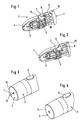
- FIGS. 6 and 7 show a further exemplary embodiment of a pressure part 4 of a puncturing device.
- the illustrated pressing member 4 is formed as a compression cone, with which the sample extraction is supported by an increased blood flow of the tissue at the puncture site.
- a material for the illustrated compression cone for example, rubber-elastic plastics are.
- the pressure member 4 has a funnel-shaped pressure ring 30 which sits on a frusto-conical support portion 31.
- the inner surfaces of the pressure ring 30 nestle against the skin and cause increased blood flow of the arching into the pressure member 4 in tissue. If the pressure acting on the pressing part 4 exceeds a predetermined minimum pressure, then the pressing part 4 moves from the first configuration shown in FIG. 6 into the second configuration shown in FIG. 7, in that the walls of the carrier region 31 noticeably yield to the user.
- the folding over of the pressing part 4 from the first state shown in FIG. 6 to the second state shown in FIG. 7 can be detected, for example, by an electrical contact which is closed when a suitable point 34 on the inside of the carrier region 31 contacts a base ring 35.
- the deformation of the pressing part 4 can be detected, for example, by means of an optical sensor. Further details and advantages of the compression cone described are in the WO 01/89383 A2 described in this regard by reference is made to the subject of the present application.
- test parameter it is thus also determined as the test parameter whether a pressure is applied to the pressure part 4 which exceeds a predetermined minimum contact pressure.
- This test parameter is relevant to the sample collection probability at which a useful sample is obtained by initiating a puncture motion under the present conditions characterized by the test parameter. If the predeterminedußanpreßtik is exceeded, it can be assumed that a puncture wound can be produced a puncture wound, which provides a useful sample.
- test device may further comprise a sensor with which the blood flow condition of a body part lying against the pressure part 4 can be determined as the test parameter.
- the condition of circulation is of great importance for the question of whether a useful sample can be obtained by means of a puncturing movement with set penetration depth can. For example, if a fingertip pressed against an opening of the pressure member, so the skin surface bulges into the opening of the pressing part 4 inside. This is shown schematically in FIG. The state of perfusion of the tissue 40 bulging into the opening depends inter alia on the orientation of the pressure element 4 to the finger and the contact pressure.
- the measurement of the circulatory state is based on the spectral absorption characteristic of hemoglobin.
- a two-wavelength measuring method is used, since corresponding sensors can be made very compact.
- the tissue is irradiated with primary light 41 at the puncture site and the spectral intensity of the remitted light 42 is measured at two wavelengths ⁇ 1, ⁇ 2.
- These two wavelengths ⁇ 1, ⁇ 2 are selected so that hemoglobin has a high absorption at one of these two wavelengths and the lowest possible absorption at the other wavelength as well as the tissue 40. From the ratio of the light intensities of the remitted light 42 at the two wavelengths ⁇ 1, ⁇ 2, it is possible to deduce the hemoglobin content of the tissue 40 and thus the blood circulation state of the body part. It is important only that the ratio of the spectral light intensities I ( ⁇ 1), I ( ⁇ 2) of the primary light 41 at the two wavelengths ⁇ 1, ⁇ 2 is known. If necessary, this ratio can be determined by a separate measurement of primary light 41. Preferably, however, a primary light source is used in which the ratio of the two light intensities I ( ⁇ 1): I ( ⁇ 2) is constant.
- the principle of the described two-wavelength measuring method is shown schematically.
- the two wavelengths are represented by two arrows ⁇ 1, ⁇ 2, which indicate the tissue 40 to be examined.
- Light of the wavelength ⁇ 1 is strongly absorbed by hemoglobin, so that the spectral intensity I ( ⁇ 1) at the wavelength ⁇ 1 in the remitted light 42 is very small relative to the spectral intensity I ( ⁇ 2) at the wavelength ⁇ 2.
- the ratio of the light intensities I ( ⁇ 1): I ( ⁇ 2) of the remitted light 42 at the two wavelengths ⁇ 1, ⁇ 2 can be used as the test parameter.
- a critical threshold it can be determined whether, under the conditions characterized by the test parameter thus obtained, a puncture would likely result in the recovery of a useful sample.
- a particularly high level of user comfort is provided by lancing systems, with which not only a puncture wound is produced, but which additionally also include a sample receiving unit with which a body fluid sample is taken after a puncture during a collection phase.
- the sample receiving unit is integrated into the piercing element, for example by the piercing element having a capillary channel into which body fluid penetrates during the collecting phase.
- sample taking does not require any additional handling steps for the user. This is an important advantage especially for users whose motor mobility is limited by age or illness.
- the puncturing device 2 includes a measuring unit for examining a recovered body fluid sample for a medically important analyte, for example glucose.
- a medically important analyte for example glucose.
- the test device preferably remains active until the end of the collection phase and indicates a change of the at least one test parameter which is disadvantageous for a sample recording by means of a warning signal.
- such a warning signal enables a user to react to an adverse change in the test parameter, so that (if necessary) a decreasing contact pressure can be increased again or incorrect positioning of the body part can be corrected.
- the testing device is connected to the measuring unit, so that an analysis of the sample obtained is prevented when occurring during the collection phase critical change of a test parameter.
- an analysis of the sample obtained is prevented when occurring during the collection phase critical change of a test parameter.
- erroneous measurement results that could, for example, mislead a user into incorrect insulin dosing, can be avoided.
- a further advantage of this measure is that with measuring units which use a test element separate from the lancing element for the purpose of examining a body fluid sample, the unnecessary use of such a test element can be saved.
- the lancing system 1 shown in FIG. 9 largely corresponds in its structure to the lancing system described with reference to FIG. It comprises a puncturing device 2 and lancing elements 3 intended for single use, which are inserted into the puncturing device 2.
- the puncturing device 2 is pressed with its pressure part 4 against a skin surface of a user.
- the pressure member 4 is displaceable relative to a housing part 7 against the spring force of a spring 5 such that the pressure member 4 passes upon application of a predetermined minimum pressure relative to the housing part 7 from the initial position shown in Figure 9 in an end position, which is shown in Fig. 10 ,
- the spring element 5 thus represents the pressure sensor of a test device with which it can be determined as the test parameter whether a pressure is applied to the pressure element 4 which exceeds a predetermined minimum contact pressure.
- the pressing member 4 is rigidly coupled with a lancing element drive (not shown), so that a set penetration depth is not influenced by a displacement of the pressure member 4 relative to the housing part 7.
- the housing part 7 is designed for this purpose as a sleeve which surrounds an inner device part, to which the pressing part 4 and the lancing element drive belong.
- the force acting between the pressure member 4 and the housing part 7 spring 5 is formed as a helical spring, which is supported at one end to a shoulder of the housing part 7 and is fastened with its other end to the pressure member 4.
- the illustrated lancing device 2 has a release means 8, by the actuation of a user after the Pressing the pressure member 4 can trigger a puncture movement.
- the triggering means 8 is designed as a button, which can only be pressed when it is aligned with a matching recess 10 of the housing part 7. This is the case when the housing part 7 has reached the pressing part 4 in the end position shown in Fig. 10.
- a securing device 9 is formed by a slot which opens into the recess 10 and in which the release button slides during displacement of the pressure member in the end position shown in Figure 10.
- the slot 9 is so narrow that a puncture can only be triggered when the pressing member 4 is pressed with a sufficient reliabilityanpreß réelle to a body part.
- the pressing part 4 has a visible marking 17, preferably as a color marking in the form of a coloring ring, which is visible to a user before pressing and in the in Fig. 10 illustrated end position of the pressing member 4 is hidden.
- a color marking for example, a geometric mark, such as a circle or square.
- the marking 17 can either be mounted on the pressure part as in the illustrated embodiment, and be concealed in the end position of the housing part 7. But it is also possible to provide the housing part 7 with a window with which the mark 17 cooperates. Depending on the configuration of the device, the marking can only be seen when the pressing member 4 is in the end position, or alternatively only when the pressing member 4 is in the initial position. It is also possible to attach the marking on the housing part 7 and modify the pressure part 4 accordingly, so that a mounted on the housing part 7 mark is covered either in the final position or in the initial position of the pressure member 4.
- FIGS 9 and 10 an embodiment of a lancing system 1 is shown that differs from the lancing system described with reference to FIGS 9 and 10 only in that no securing device 9 is present.
- the recess 10 of the housing part 7 is formed as a so wide slot that the trigger means 8 actuated in any position of the pressure member 4 relative to the housing part 7 and a puncture can be triggered.
Abstract
Description
Die Erfindung betrifft ein Stechsystem zum Erzeugen einer Einstichwunde für das Gewinnen einer Probe einer Körperflüssigkeit. Bei der Körperflüssigkeit handelt es sich in der Regel um Blut. In manchen Fällen geht es aber auch um die Gewinnung einer Probe von interstitieller Flüssigkeit. Nachfolgend wird ohne Beschränkung der Allgemeinheit auf Blut als Beispiel, auch für andere, aus einer Einstichwunde gewinnbare Körperflüssigkeiten, Bezug genommen.The invention relates to a lancing system for creating a puncture wound for obtaining a sample of a body fluid. The body fluid is usually blood. In some cases, it is also about obtaining a sample of interstitial fluid. In the following, blood is taken as an example, without limitation of generality, also for other body fluids recoverable from a puncture wound.
Derartige Stechsysteme bestehen in der Regel aus zur einmaligen Verwendung vorgesehenen (disposiblen) Stechelementen zum Einstechen in die Haut und einem Stechgerät mit einem Antrieb für die Stechbewegung des Stechelements. Das Stechgerät eines solchen Stechsystems hat ein Andruckteil zum Anpressen an das Körperteil, in dem eine Einstichwunde erzeugt werden soll, und ein Auslösemittel, durch dessen Betätigung ein Benutzer eine Einstichbewegung eines Stechelements auslösen kann.Such lancing systems generally consist of disposable lancing elements for piercing the skin and a puncturing device with a drive for the lancing movement of the lancing element. The puncturing device of such a lancing system has a pressing member for pressing against the body part in which a puncture wound is to be generated, and a triggering means, by the actuation of which a user can initiate a puncturing movement of a piercing element.
Ein ständiges Ziel in der Entwicklung von Stechsystemen besteht darin, mit möglichst geringem Schmerz eine Einstichwunde zu erzeugen, aus der sich eine brauchbare Probe, d.h. eine ausreichende Menge einer Körperflüssigkeit, gewinnen läßt. Sowohl für das Schmerzempfinden als auch für die Probengewinnung ist die Einstichtiefe von großer Bedeutung. Generell gilt, daß das Schmerzempfinden mit zunehmender Einstichtiefe ebenso wie die Flüssigkeitsmenge, die sich aus der Einstichwunde gewinnen läßt, zunehmen. An Stechgeräte besteht deshalb die Anforderung, die Einstichtiefe einerseits so gering wie möglich, andererseits so tief wie nötig zu gestalten.A constant goal in the development of lancing systems is to create a puncture wound with as little pain as possible, from which a useful sample, i. a sufficient amount of a body fluid, win. The puncture depth is of great importance for both pain sensation and sample collection. In general, it is true that the sensation of pain increases with increasing penetration depth as well as the amount of fluid that can be gained from the puncture wound. Therefore, there is a requirement for punches to make the penetration depth on the one hand as small as possible and on the other hand as deep as necessary.
In diesem Zusammenhang stellt der Anpreßdruck, mit dem das Andruckteil an ein Körperteil angepreßt wird, einen wichtigen Prüfparameter dar. Bei einem zu geringen Anpreßdruck kann es dazu kommen, daß bei einem Einstich nicht die gewünschte Einstichtiefe erreicht wird und deshalb keine brauchbare Probe gewonnen werden kann. In einem solchen Fall muß die Einstichprozedur wiederholt werden, was für einen Benutzer äußerst unangenehm ist.In this context, the contact pressure with which the pressure member is pressed against a body part, an important test parameter. If the contact pressure is too low, it may happen that the desired penetration depth is not achieved in a puncture and therefore no useful sample can be obtained , In such a case, the puncture procedure must be repeated, which is extremely uncomfortable for a user.
Um das Risiko eines erfolglosen Einstichs zu reduzieren, sind beispielsweise aus der
Ein Einstichgerät mit einem eingebauten Drucksensor wird auch in der
Aus der
Aufgabe der Erfindung ist es, einen Weg aufzuzeigen, wie mit möglichst großem Benutzerkomfort bei einem Stechsystem das Risiko eines erfolglosen Einstichs, der nicht zur Gewinnung einer brauchbaren Probe führt, reduziert werden kann, ohne daß durch eine unnötige große Einstichtiefe das Schmerzempfinden erhöht wird.The object of the invention is to show a way how to maximize user comfort in a lancing system, the risk of an unsuccessful puncture, which does not lead to the recovery of a useful sample, can be reduced without the pain sensation is increased by an unnecessary large penetration depth.
Diese Aufgabe wird gelöst durch ein Stechsystem zum Erzeugen einer Einstichwunde für das Gewinnen einer Probe einer Körperflüssigkeit, umfassend ein Andruckteil zum Anpressen an ein Körperteil, in dem eine Einstichwunde erzeugt werden soll, ein Auslösemittel, durch dessen Betätigung ein Benutzer nach dem Anpressen des Andruckteils eine Einstichbewegung eines Stechelements auslösen kann, eine Prüfeinrichtung zum Ermitteln mindestens eines Prüfparameters, von dem eine Probengewinnungswahrscheinlichkeit abhängt, eine Sicherungseinrichtung, die in einem Sperrzustand das Auslösemittel sperrt, so daß keine Einstichbewegung ausgelöst werden kann, und in einem Auslösezustand das Auslösemittel freigibt, so daß durch dessen Betätigung eine Einstichbewegung ausgelöst werden kann, wobei die Sicherungseinrichtung von der Prüfeinrichtung aus dem Sperrzustand in den Auslösezustand versetzt wird, wenn der von der Prüfeinrichtung festgestellte Prüfparameter festgelegten Mindestanforderungen genügt, und eine Signaleinrichtung zum Signalisieren eines Übergangs der Sicherungseinrichtung von dem Sperrzustand in den Auslösezustand und/oder zum Signalisieren, daß sich die Sicherungseinrichtung in dem Auslösezustand befindet.This object is achieved by a puncture system for generating a puncture wound for obtaining a sample of a body fluid, comprising a pressure member for pressing against a body part in which a puncture wound is to be generated, a trigger means, by the actuation of a user after pressing the pressure part a A puncturing movement of a lancing element can trigger, a test device for determining at least one test parameter, on which a sample collection probability depends, a safety device, which in a Locking the trigger means locks, so that no puncture can be triggered, and releases the triggering means in a triggering state, so that its actuation a puncture can be triggered, wherein the securing device is offset from the test device from the locked state to the trigger state, if the of the test device determined minimum test requirements, and a signaling device for signaling a transition of the safety device from the locked state to the trip state and / or to signal that the safety device is in the tripping state.
Unter der Probengewinnungswahrscheinlichkeit ist dabei die Wahrscheinlichkeit zu verstehen, mit der durch das Auslösen einer Einstichbewegung unter den vorliegenden Bedingungen, die durch den oder die ermittelten Prüfparameter charakterisiert sind, eine brauchbare Probe gewonnen wird.The probability of obtaining the sample is understood to be the probability with which a usable sample is obtained by triggering a puncturing movement under the present conditions, which are characterized by the test parameter (s) determined.
Die Aufgabe wird ferner gelöst durch ein Verfahren zum Vorbereiten eines Stechsystems zum Erzeugen einer Einstichwunde für das Gewinnen einer Körperflüssigkeit, wobei mindestens ein Prüfparameter ermittelt wird, von dem die Probengewinnungswahrscheinlichkeit abhängt, geprüft wird, ob der mindestens eine festgestellte Prüfparameter festgelegten Mindestanforderungen genügt, und falls dies der Fall ist, eine Sicherungseinrichtung aus einem Sperrzustand in einen Auslösezustand versetzt wird, wobei in dem Auslösezustand durch Betätigen eines Auslösemittels ein Benutzer eine Einstichbewegung eines Stechelements auslösen kann und in dem Sperrzustand das Auslösemittel gesperrt ist, so daß keine Einstichbewegung ausgelöst werden kann, und der Übergang der Sicherungseinrichtung von dem Sperrzustand in den Auslösezustand und/oder die Tatsache, daß sich die Sicherungseinrichtung in dem Auslösezustand befindet, einem Benutzer durch ein Signal mitgeteilt wird.The object is further achieved by a method for preparing a lancing system for generating a puncture wound for obtaining a body fluid, wherein at least one test parameter is determined, on which the sample collection probability depends, it is checked whether the at least one determined test parameter meets specified minimum requirements, and if this is the case, a safety device is placed from a locked state into a trigger state, wherein in the trigger state by actuating a trigger means a user can trigger a puncture movement of a lancing element and locked in the blocking state, the triggering means, so that no puncture can be triggered, and the transition of the securing device from the locked state to the release state and / or the The fact that the safety device is in the tripping state is communicated to a user by a signal.
Im Rahmen der vorliegenden Erfindung wurde erkannt, daß ein automatisches Auslösen der Einstichbewegung durch eine Prüfeinrichtung in Form eines Drucksensors, wie es beispielsweise bei dem aus der
Auf der anderen Seite können bei Verwendung eines Druckmeßgeräts mit einer Druckbereichsanzeige gemäß der
Durch ein erfindungsgemäßes Stechsystem lassen sich die Nachteile der bekannten Geräte beheben, indem die Prüfeinrichtung mit einer Sicherungseinrichtung zusammenwirkt. Wenn der von der Prüfeinrichtung festgestellte Prüfparameter festgelegten Mindestanforderungen genügt, wird die Sicherungseinrichtung von der Prüfeinrichtung betätigt, so daß diese aus einem Sperrzustand, in dem sie das Auslösemittel sperrt, in einen Auslösezustand übergeht, in dem das Auslösemittel entsichert ist, so daß durch dessen Betätigung eine Einstichbewegung ausgelöst werden kann. Der Übergang der Sicherungseinrichtung wird dem Benutzer bevorzugt durch ein akustisches Signal mitgeteilt. Um anzuzeigen, daß sich die Sicherungseinrichtung in dem Auslösezustand befindet, kann beispielsweise ein Piepton in kurzen Zeitabständen wiederholt oder ein Signallicht eingeschaltet werden.By a puncturing system according to the invention, the disadvantages of the known devices can be eliminated by the test device cooperating with a safety device. If the test parameter determined by the tester satisfies specified minimum requirements, the safety device is actuated by the test device so that it switches from a locked state in which it locks the triggering means to a triggering state in which the triggering means is unlocked so that it is actuated a puncture movement can be triggered. The transition of the security device is preferably communicated to the user by an acoustic signal. To indicate that the safety device is in the triggering state, for example, a beep repeated at short intervals or a signal light can be turned on.
Auf diese Weise wird einerseits gewährleistet, daß ein Einstich nur dann erfolgt, wenn ein Benutzer das Auslösemittel betätigt. Der Benutzer hat somit die Kontrolle über den Zeitpunkt, zu dem ein Einstich erfolgt, was aus psychologischen Gründen für das Schmerzempfinden von großer Bedeutung ist. Andererseits kann verhindert werden, daß ein Einstich ausgelöst wird, wenn Prüfparameter, wie beispielsweise der Anpreßdruck, erwarten lassen, daß ein Einstich erfolglos bleiben wird. Bei einem erfindungsgemäßen Stechsystem kommt es also nur dann zu einem Einstich, wenn sowohl von der Prüfeinrichtung ein Prüfparameter festgestellt wird, der einen erfolgreichen Einstich erwarten läßt, als auch das Auslösemittel von dem Benutzer betätigt wird.In this way, on the one hand ensures that a puncture takes place only when a user actuates the release means. The user thus has control over the time when a puncture takes place, which is of great psychological importance for the sensation of pain. On the other hand, it can be prevented that a puncture is triggered when test parameters, such as the contact pressure, expect that a puncture will remain unsuccessful. In a lancing system according to the invention, therefore, a puncture occurs only when a test parameter is determined both by the test device, which can be expected a successful puncture, and the release means is actuated by the user.
Der mit der Prüfeinrichtung eines erfindungsgemäßen Stechsystems festgestellte Prüfparameter kann beispielsweise der Anpreßdruck sein, mit dem das Andruckteil an ein Körperteil, in dem eine Einstichwunde erzeugt werden soll, angepreßt wird. Drucksensoren können beispielsweise als drucksensitives Element eine Feder enthalten. Geeignet sind ferner kapazitive Sensoren, bei denen als Maß für den Anpreßdruck eine Kapazitätsänderung auftritt, und piezoelektrische Sensoren. Alternativ oder zusätzlich kann auch die Position des Körperteils in Relation zu dem Andruckteil als Prüfparameter verwendet werden. Beispielsweise kann das Andruckteil eine relativ große Öffnung aufweisen, in die sich die Haut eines angepreßten Körperteils, beispielsweise einer Fingerbeere, abhängig von elastischen Eigenschaften der Haut je nach Patient und Handhabung unterschiedlich weit hineinwölbt. Ein weiterer möglicher Prüfparameter ist der Durchblutungszustand des an dem Andruckteil anliegenden Körperteils.The test parameter determined with the testing device of a puncturing system according to the invention can be, for example, the contact pressure with which the pressure element is pressed against a body part in which a puncture wound is to be produced. For example, pressure sensors may include a spring as a pressure-sensitive element. Also suitable are capacitive sensors in which a capacitance change occurs as a measure of the contact pressure, and piezoelectric sensors. Alternatively or additionally, the position of the body part in relation to the pressure part can also be used as the test parameter. For example, the pressure member may have a relatively large opening into which the skin of a pressed-body part, such as a fingertip, depending on the elastic properties of the skin varies depending on the patient and handling different degrees. Another possible test parameter is the perfusion state of the body part resting on the pressure part.
Der Durchblutungszustand kann beispielsweise mit einem optischen Sensor zur Blutsauerstoffmessung ermittelt werden. Die dafür verwendete Meßtechnik nutzt die spektrale Absorptionscharakteristik des Hämoglobins aus, beispielsweise indem ein Lichtstrahl mit definierten spektralen Intensitäten bei zwei unterschiedlichen Wellenlängen auf das anliegende Körperteil eingestrahlt wird. Das von dem Körperteil remittierte Licht wird untersucht, wobei aus der unterschiedlichen Absorption bei den beiden Wellenlängen auf den Hämoglobingehalt und damit den Durchblutungszustand des Körperteils geschlossen werden kann. Geeignete Sensoren sind beispielsweise von der Firma NONIN Medical Inc., USA, erhältlich und werden von dieser in Meßgeräten eingebaut, die unter der Marke 9500 Onyx vertrieben werden.The blood circulation state can be determined, for example, with an optical sensor for blood oxygen measurement. The measuring technique used for this purpose exploits the spectral absorption characteristic of the hemoglobin, for example by irradiating a light beam with defined spectral intensities at two different wavelengths onto the adjoining body part. The light remitted by the body part is examined, it being possible to deduce the hemoglobin content and thus the blood circulation state of the body part from the different absorption at the two wavelengths. Suitable sensors are available, for example, from NONIN Medical Inc., USA, and are incorporated by them into meters sold under the brand name 9500 Onyx.
Ein weiterer Aspekt der Erfindung, der auch für ein Stechsystem ohne eine Sicherungseinrichtung selbständige Bedeutung haben kann, besteht darin, daß ein Benutzer beim Ausrichten eines Andruckteils auf das Körperteil, in dem eine Einstichwunde erzeugt werden soll, durch Signale unterstützt wird, die dem Benutzer eine Information über die Orientierung des Andruckteils zu dem Körperteil vermitteln. Insbesondere für ältere Patienten ist es mühsam, den richtigen Umgang mit einem Stechsystem zu erlernen. Vielen Patienten bereitet dabei das korrekte Ausrichten des Körperteils, insbesondere hinsichtlich Position und Anpreßdruck auf den Andruckteil, Probleme.Another aspect of the invention, which may also have independent significance for a lancing system without a safety device, is that a user when aligning a pressure on the body part in which a puncture wound is to be generated, is supported by signals that the user Convey information about the orientation of the pressure part to the body part. Especially for older patients, it is difficult to learn how to handle a lancing system correctly. Many patients prepare the correct alignment of the body part, in particular with regard to position and contact pressure on the pressure part, problems.
Durch eine Prüfeinrichtung kann dem Benutzer diesbezüglich eine Rückmeldung gegeben werden, so daß die korrekte Handhabung des Stechsystems leichter und schneller erlernt werden kann. Bevorzugt ermöglicht die Prüfeinrichtung eine visuelle Kontrolle des an dem Körperteil anliegenden Andruckteils und/oder des an dem Andruckteil anliegenden Körperteils. Beispielsweise kann hierfür in das Stechgerät eine Kamera integriert sein, so daß ein entsprechendes Bild aufgenommen und mittels einer Anzeigeeinrichtung angezeigt werden kann. Anstelle einer Kamera kann eine visuelle Kontrolle auch mit passiven optischen Elementen, beispielsweise Spiegeln und/oder Linsen, ermöglicht werden.By means of a test device, the user can be given a feedback in this regard, so that the correct handling of the lancing system can be learned more easily and more quickly. Preferably, the test device allows a visual inspection of the pressure applied to the body part pressing part and / or the voltage applied to the pressure member body part. For example, for this purpose, a camera can be integrated into the puncturing device so that a corresponding image can be taken and displayed by means of a display device. Instead of a camera, a visual control can also be made possible with passive optical elements, for example mirrors and / or lenses.
Allgemein gesagt kann die Prüfeinrichtung den Benutzer beim Ausrichten des Andruckteils auf das Körperteil auch durch optische, akustische oder sonstige Signale unterstützen. Beispielsweise kann das Andruckteil so ausgebildet sein, daß es sich für den Benutzer fühlbar verformt, sobald ein Druck aufgebracht wird, der einen vorgegebenen Mindestanpreßdruck übersteigt. Auf diese Weise kann ein tastbares Signal erzeugt werden.Generally speaking, the test device can assist the user in aligning the pressure part on the body part by optical, acoustic or other signals. For example, the pressure member may be formed so that it is noticeably deformed for the user as soon as a pressure is applied which exceeds a predetermined Mindestanpreßdruck. In this way, a tactile signal can be generated.
Weitere Einzelheiten und Vorteile der Erfindung werden anhand von Ausführungsbeispielen unter Bezugnahme auf die beigefügten Zeichnungen erläutert. Gleiche oder einander entsprechende Bauteile sind dabei mit übereinstimmenden Bezugszeichen gekennzeichnet.Further details and advantages of the invention will be explained by means of embodiments with reference to the accompanying drawings. Identical or corresponding components are identified by matching reference numerals.
Die im folgenden beschriebenen Merkmale können einzeln oder in Kombination verwendet werden, um bevorzugte Ausgestaltungen der Erfindung zu schaffen. Es zeigen:
- Fig. 1
- ein Ausführungsbeispiel eines erfindungsgemäßen Stechsystems in einer teilweise geschnittenen Seitenansicht;
- Fig. 2
- das in
Figur 1 dargestellte Ausführungsbeispiel in einem entsicherten Zustand; - Fig. 3
- ein weiteres Ausführungsbeispiel eines erfindungsgemäßen Stechsystems in einer Seitenansicht;
- Fig. 4
- das in
Figur 3 dargestellte Ausführungsbeispiel mit durch Druck verformtem Andruckteil; - Fig. 5
- das Andruckteil eines weiteren Ausführungsbeispiels eines erfindungsgemäßen Stechsystems im Querschnitt;
- Fig. 6
- ein weiteres Ausführungsbeispiel eines Andruckteils eines erfindungsgemäßes Stechsystems in einer Seitenansicht;
- Fig. 7
- das in
Figur 6 dargestellte Andruckteil mit einem angepreßten Finger; - Fig. 8
- eine Prinzipskizze zur Messung des Durchblutungszustands eines an dem Andruckteil anliegenden Körperteils;
- Fig. 9
- ein weiteres Ausführungsbeispiel eines erfindungsgemäßen Stechsystems in einer teilweise geschnittenen Seitenansicht;
- Fig. 10
- das in Fig. 9 dargestellte Ausführungsbeispiel unter Einwirkung eines Anpreßdrucks;
- Fig. 11
- ein weiteres Ausführungsbeispiel des erfindungsgemäßen Stechsystems in einer teilweise geschnittenen Seitenansicht; und
- Fig. 12
- das in Fig. 11 dargestellte Ausführungsbeispiel unter Einwirkung eines Anpreßdrucks.
- Fig. 1
- an embodiment of a lancing system according to the invention in a partially sectioned side view;
- Fig. 2
- the embodiment shown in Figure 1 in an unlocked state;
- Fig. 3
- a further embodiment of a lancing system according to the invention in a side view;
- Fig. 4
- the embodiment shown in Figure 3 with pressure-deformed pressure member;
- Fig. 5
- the pressure member of a further embodiment of a lancing system according to the invention in cross section;
- Fig. 6
- a further embodiment of a pressure member of a puncturing system according to the invention in a side view;
- Fig. 7
- the pressure member shown in Figure 6 with a pressed finger;
- Fig. 8
- a schematic diagram for measuring the blood circulation state of a voltage applied to the pressure member body part;
- Fig. 9
- a further embodiment of a lancing system according to the invention in a partially sectioned side view;
- Fig. 10
- the embodiment shown in Figure 9 under the action of a contact pressure.
- Fig. 11
- a further embodiment of the lancing system according to the invention in a partially sectioned side view; and
- Fig. 12
- the embodiment shown in Fig. 11 under the action of a contact pressure.
Das in Figur 1 dargestellte Stechsystem 1 umfaßt ein Stechgerät 2 und zur einmaligen Verwendung vorgesehene Stechelemente 3, die in das Stechgerät 2 eingesetzt werden. Zum Erzeugen einer Einstichwunde wird das Stechgerät 2 mit seinem Andruckteil 4 an eine Hautoberfläche eines Benutzers angepreßt. Überschreitet der dabei ausgeübte Anpreßdruck einen durch die Stärke einer Feder 5 festgelegten Mindestdruck, so wird das Andruckteil 4 gegen eine Kante 6 des Gerätegehäuses 7 geschoben.The
Das dargestellte Stechgerät 2 weist ein Auslösemittel 8 auf, durch dessen Betätigung ein Benutzer nach dem Anpressen des Andruckteils 4 eine Einstichbewegung auslösen kann. Bei dem dargestellten Ausführungsbeispiel ist das Auslösemittel 8 als Knopf ausgebildet. Um zu gewährleisten, daß nur dann ein Einstich ausgelöst wird, wenn dieser voraussichtlich zur Gewinnung einer brauchbaren Probe führt, ist das Stechgerät 2 mit einer Sicherungseinrichtung 9 ausgestattet, die in dem in Figur 1 dargestellten Sperrzustand das Auslösemittel 8 sperrt, so daß keine Einstichbewegung ausgelöst werden kann, und in einem in Figur 2 dargestellten Auslösezustand das Auslösemittel 8 freigibt, so daß durch dessen Betätigung eine Einstichbewegung ausgelöst werden kann.The illustrated
Bei dem dargestellten Ausführungsbeispiel ist die Sicherungseinrichtung 9 als eine an dem Andruckteil 4 angebrachte Sperrzunge ausgebildet. In dem in Figur 1 dargestellten Sperrzustand wird das als Auslöseknopf ausgebildete Auslösemittel 8 mechanisch von der Sperrzunge 9 blockiert. Die Sperrzunge 9 hat eine Aussparung 10. Wird das Andruckteil 4 gegen die Kante 6 des Gerätegehäuses 7 geschoben, so wird auch die Sperrzunge 9 gegenüber dem Auslöseknopf 8 verschoben, bis die Aussparung 10 mit dem Auslöseknopf 8 fluchtet und so der in Figur 2 dargestellte Auslösezustand der Sicherungseinrichtung 9 erreicht wird. In diesem Zustand ist der Auslöseknopf 8 nicht mehr blockiert, so daß durch Drücken des Auslöseknopfs 8 eine Einstichbewegung ausgelöst werden kann.In the illustrated embodiment, the securing device 9 is formed as a attached to the
Alternativ kann die Sicherungseinrichtung 9 auch als Schalter eines Auslösestromkreises ausgebildet sein. Beispielsweise kann eine Einstichbewegung durch Schließen des Auslösestromkreises ausgelöst werden, wobei ein erster Schalter, der von der Sicherungseinrichtung gebildet und bei Kontakt des Andruckteils 4 mit der Gehäusekante geschlossen wird, und ein zweiter Schalter, der durch Betätigen des Auslösemittels 8 geschlossen wird, in dem Stromkreis angeordnet sind.Alternatively, the securing device 9 can also be designed as a switch of a trip circuit. For example, a puncture movement can be triggered by closing the trip circuit, wherein a first switch, which is formed by the securing device and is closed upon contact of the
Das dargestellte Stechsystem hat den wichtigen Vorteil, daß der Benutzer durch Betätigen des Auslösemittels 8 nur dann einen Einstich auslösen kann, wenn der Anpreßdruck so hoch ist, daß eine Einstichbewegung voraussichtlich eine brauchbare Körperflüssigkeitsprobe liefert. Erfolglose Einstiche werden durch eine Prüfeinrichtung, die bei dem dargestellten Ausführungsbeispiel einen Drucksensor in Form einer Feder 5 umfaßt, vermieden.The illustrated lancing system has the important advantage that the user can trigger a puncture by operating the trigger means 8 only when the contact pressure is so high that a puncture movement is expected to provide a useful body fluid sample. Unsuccessful punctures are provided by a testing device, the the illustrated embodiment comprises a pressure sensor in the form of a
Der Übergang der Sicherungseinrichtung 9 aus dem Sperrzustand in den Auslösezustand wird einem Benutzer durch ein geeignetes Signal angezeigt. Zu diesem Zweck dient eine Signaleinrichtung 12, beispielsweise eine Leuchtdiode, mit der durch ein Leuchtsignal angezeigt wird, daß sich die Sicherungseinrichtung 9 in dem Auslösezustand befindet und folglich durch Betätigen des Auslösemittels 8 ein Einstich ausgelöst werden kann. Alternativ oder zusätzlich kann die Signaleinrichtung 12 auch ein akustisches Signal, beispielsweise einen Piepton, erzeugen, um den Übergang der Sicherungseinrichtung 9 in den Auslösezustand anzuzeigen.The transition of the security device 9 from the lock state to the release state is indicated to a user by a suitable signal. For this purpose, a
In den Figuren 3 und 4 ist ein weiteres Ausführungsbeispiel eines Stechsystems dargestellt, bei dem die Prüfeinrichtung des Stechgeräts 2 einen Drucksensor in Form eines Schnappelements 15 umfaßt, das bei Einwirkung eines kritischen Mindestdrucks aus einer ersten Konfiguration, die in Figur 3 dargestellt ist, in eine zweite Konfiguration, die in Figur 4 dargestellt ist, schnappt. Ein derartiges Schnappelement stellt einen besonders vorteilhaften Drucksensor dar, der auch für Stechsysteme ohne eine Sicherungseinrichtung vorteilhaft zu verwenden ist und deshalb einen Aspekt der Erfindung darstellt, der auch selbständige Bedeutung hat. Das Schnappelement 15 kann beispielsweise ein Metallblech sein, das beim Umschnappen ein hörbares Knackgeräusch erzeugt. In der in Figur 3 dargestellten ersten Konfiguration hat das Schnappelement 15 eine kegelstumpfähnliche Form mit einer Öffnung 16, in die sich eine Hautoberfläche eines angelegten Körperteils hineinwölben kann.In the figures 3 and 4, another embodiment of a lancing system is shown, in which the testing device of the lancing
Sobald eine Mindestandruckkraft von beispielsweise 10 Newton in Pfeilrichtung F auf das Schnappelement 15 ausgeübt wird, schnappt es hör- und fühlbar in die in Figur 4 dargestellte zweite Konfiguration. In dieser Konfiguration bleibt es, solange ein Haltedruck ausgeübt wird, der etwas geringer als der zum Umschnappen in die zweite Konfiguration erforderliche kritische Mindestdruck ist und beispielsweise 7 Newton beträgt. Wird dieser Haltedruck unterschritten, so schnappt das Schnappelement 15 federnd in seine erste Konfiguration zurück.Once a Mindestandruckkraft exerted, for example, 10 Newton in the direction of arrow F on the
Der kritische Mindestdruck, bei dessen Überschreiten das Schnappelement 15 aus der ersten Konfiguration in die zweite Konfiguration schnappt, und der Haltedruck, bei dessen Unterschreiten das Schnappelement 15 aus der zweiten Konfiguration zurück in die erste Konfiguration schnappt, unterscheiden sich bevorzugt um wenige Newton, beispielsweise 1 bis 3 Newton. Wichtig ist, daß der Haltedruck so gewählt wird, daß bei Anpressen des Andruckteils 4 mit dem Haltedruck an ein Körperteil Bedingungen vorliegen, die mit möglichst hoher Wahrscheinlichkeit erwarten lassen, daß das Auslösen einer Einstichbewegung eine Einstichwunde erzeugt, mit der eine brauchbare Probe gewonnen wird.The critical minimum pressure beyond which the
Das beschriebene Schnappelement 15 stellt ein Beispiel für eine Signaleinrichtung dar, die in die Prüfeinrichtung integriert ist, da durch das Umschnappen sowohl festgestellt wird, daß der als Prüfparameter erfaßte Anpreßdruck festgelegten Mindestanforderungen genügt, als auch ein akustisches Signal erzeugt wird.The
In Figur 5 sind das Andruckteil 4 und die Prüfeinrichtung 20 eines weiteren Ausführungsbeispiels in einer Querschnittsansicht dargestellt. Die Prüfeinrichtung 20 dieses Ausführungsbeispiels hat den Vorteil, daß zusätzlich zu dem Anpreßdruck auch die Ausrichtung des Andruckteils 4 relativ zu einem anliegenden Körperteil geprüft werden kann. Die Prüfeinrichtung 20 umfaßt zu diesem Zweck mehrere, bei dem dargestellten Ausführungsbeispiel zwei, Sensorstifte 21, die in ihrer Längsrichtung beweglich angeordnet sind. Wird auf das Andruckteil 4 Druck ausgeübt, so werden die Sensorstifte 21 gegen ein Kippelelement 22 geschoben, das bei dem dargestellten Ausführungsbeispiel als Ring ausgebildet ist. Das Kippelement 22 ist auf einem Sensorelement 23 so gelagert, daß es kippt, wenn die Sensorstifte 21 um unterschiedliche Strecken zurückgeschoben wurden. Nur wenn die Sensorstifte 21 um gleiche Strecken zurückgeschoben wurden, wird der auf den Sensorstiften 21 lastende Anpreßdruck auf das Sensorelement 23 übertragen, so daß dieses gegen eine Rückstellfeder (nicht dargestellt) zurückgeschoben wird.FIG. 5 shows the
Wird bei der beschriebenen Prüfeinrichtung das Sensorelement 23 um eine kritische Strecke zurückgeschoben, die durch die Härte der Rückstellfeder vorgegeben werden kann, so bedeutet dies, daß der auf den Sensorstiften 21 lastende Druck im wesentlichen gleichmäßig verteilt ist und einen kritischen Mindestanpreßdruck übersteigt.If in the described test device, the
Die anhand von Figur 5 beschriebene Prüfeinrichtung umfaßt also einen Drucksensor, mit dem feststellbar ist, ob das Andruckteil 4 auf eine Hautoberfläche einen im voraus festgelegten Druck ausübt, und ob gleichzeitig das Andruckteil 4 so ausgerichtet ist, daß eine Einstichbewegung eines Stechelements 3 im wesentlichen senkrecht zu der Hautoberfläche erfolgen würde. Als Prüfparameter kann auf diese Weise unter anderem die Orientierung des Andruckteils 4 zu dem anliegenden Körperteil ermittelt werden. Wird die beschriebene Prüfeinrichtung 20 an eine Anzeigeeinrichtung angeschlossen, so kann ein Benutzer bei dem Ausrichten des Andruckteils auf das Körperteil, in dem eine Einstichwunde erzeugt werden soll, durch Signale unterstützt werden, die dem Benutzer eine Information über die Orientierung des Andruckteils 4 zu dem Körperteil vermitteln.The test device described with reference to Figure 5 thus comprises a pressure sensor with which it can be determined whether the
Der anhand von Figur 5 beschriebene Drucksensor, mit dem eine Positionserkennung möglich ist, ist in anderem Zusammenhang, nämlich für ein Gerät zur nadellosen Injektion von Medikamenten, bekannt und in der
In den Figuren 6 und 7 ist ein weiteres Ausführungsbeispiel eines Andruckteils 4 eines Stechgeräts dargestellt. Das dargestellte Andruckteil 4 ist als Kompressionskonus ausgebildet, mit dem die Probengewinnung durch eine erhöhte Durchblutung des Gewebes an der Einstichstelle unterstützt wird. Als Material für den dargestellte Kompressionskonus eignen sich beispielsweise gummielastische Kunststoffe.FIGS. 6 and 7 show a further exemplary embodiment of a
Das Andruckteil 4 hat einen trichterförmigen Andruckring 30, der auf einem kegelstumpfförmigen Trägerbereich 31 sitzt. Beim Anlegen eines Körperteils 32 schmiegen sich die Innenflächen des Andruckrings 30 an die Haut an und bewirken eine erhöhte Durchblutung des sich in das Andruckteil 4 hinein wölbenden Gewebes. Übersteigt der auf dem Andruckteil 4 lastende Druck einen vorgegebenen Mindestdruck, so geht das Andruckteil 4 aus der in Figur 6 dargestellten ersten Konfiguration in die in Figur 7 dargestellte zweite Konfiguration über, indem die Wände des Trägerbereichs 31 für den Benutzer spürbar nachgeben.The
Das Umklappen des Andruckteils 4 aus dem in Figur 6 dargestellten ersten Zustand in den in Figur 7 dargestellten zweiten Zustand kann beispielsweise mit einem elektrischen Kontakt detektiert werden, der geschlossen wird, wenn eine geeignete Stelle 34 der Innenseite des Trägerbereichs 31 einen Basisring 35 berührt. Alternativ kann die Verformung des Andruckteils 4 beispielsweise auch mittels eines optischen Sensors detektiert werden. Weitere Einzelheiten und Vorteile des beschriebenen Kompressionskonus sind in der
Bei dem anhand der Figuren 6 und 7 beschriebenen Ausführungsbeispiel wird als Prüfparameter also ebenfalls festgestellt, ob auf dem Andruckteil 4 ein Druck lastet, der einen vorgegebenen Mindestanpreßdruck übersteigt. Dieser Prüfparameter ist für die Probengewinnungswahrscheinlichkeit relevant, mit der durch das Auslösen einer Einstichbewegung unter den vorliegenden Bedingungen, die durch den Prüfparameter charakterisiert sind, eine brauchbare Probe gewonnen wird. Wird der vorgegebene Mindestanpreßdruck überschritten, kann davon ausgegangen werden, daß mit einer Einstichbewegung eine Einstichwunde erzeugt werden kann, die eine brauchbare Probe liefert.In the embodiment described with reference to FIGS. 6 and 7, it is thus also determined as the test parameter whether a pressure is applied to the
Alternativ oder zusätzlich kann die Prüfeinrichtung ferner einen Sensor umfassen, mit dem als Prüfparameter der Durchblutungszustand eines an dem Andruckteil 4 anliegenden Körperteils ermittelbar ist.Alternatively or additionally, the test device may further comprise a sensor with which the blood flow condition of a body part lying against the
Der Durchblutungszustand ist von großer Bedeutung für die Frage, ob mittels einer Einstichbewegung mit eingestellten Einstichtiefe eine brauchbare Probe gewonnen werden kann. Wird beispielsweise eine Fingerbeere gegen eine Öffnung des Andruckteils gepreßt, so wölbt sich die Hautoberfläche in die Öffnung des Andruckteils 4 hinein. Dies ist schematisch in Figur 8 dargestellt. Der Durchblutungszustand des sich in die Öffnung hineinwölbenden Gewebes 40 hängt u.a. von der Ausrichtung des Andruckteils 4 zu dem Finger und dem Anpreßdruck ab.The condition of circulation is of great importance for the question of whether a useful sample can be obtained by means of a puncturing movement with set penetration depth can. For example, if a fingertip pressed against an opening of the pressure member, so the skin surface bulges into the opening of the
Die Messung des Durchblutungszustandes basiert auf der spektralen Absorptionscharakteristik des Hämoglobins. Bevorzugt wird ein Zwei-Wellenlängen-Meßverfahren angewandt, da sich entsprechende Sensoren sehr kompakt fertigen lassen. Bei einem Zwei-Wellenlängen-Meßverfahren wird das Gewebe an der Einstichstelle mit Primärlicht 41 bestrahlt und die spektrale Intensität des remittierten Lichts 42 bei zwei Wellenlängen λ1, λ2 gemessen.The measurement of the circulatory state is based on the spectral absorption characteristic of hemoglobin. Preferably, a two-wavelength measuring method is used, since corresponding sensors can be made very compact. In a two-wavelength measurement method, the tissue is irradiated with
Diese beiden Wellenlängen λ1, λ2 sind so gewählt, daß Hämoglobin bei einer dieser beiden Wellenlängen eine hohe Absorption und bei der anderen Wellenlänge ebenso wie das Gewebe 40 eine möglichst geringe Absorption hat. Aus dem Verhältnis der Lichtintensitäten des remittierten Lichts 42 bei den beiden Wellenlängen λ1, λ2 kann auf den Hämoglobingehalt des Gewebes 40 und damit auf den Durchblutungszustand des Körperteils geschlossen werden. Wichtig dabei ist lediglich, daß das Verhältnis der spektralen Lichtintensitäten I(λ1), I(λ2) des Primärlichts 41 bei den beiden Wellenlängen λ1, λ2 bekannt ist. Falls erforderlich kann dieses Verhältnis durch eine separate Messung von Primärlicht 41 ermittelt werden. Bevorzugt wird jedoch eine Primärlichtquelle verwendet, bei der das Verhältnis der beiden Lichtintensitäten I(λ1): I(λ2) konstant ist.These two wavelengths λ1, λ2 are selected so that hemoglobin has a high absorption at one of these two wavelengths and the lowest possible absorption at the other wavelength as well as the
In Figur 8 ist das Prinzip des beschriebenen Zwei-Wellenlängen-Meßverfahrens schematisch dargestellt. In dem Primärlicht 41 sind die beiden Wellenlängen durch zwei Pfeile λ1, λ2 dargestellt, die zu dem zu untersuchenden Gewebe 40 hindeuten. Licht der Wellenlänge λ1 wird von Hämoglobin stark absorbiert, so daß die spektrale Intensität I(λ1) bei der Wellenlänge λ1 in dem remittierten Licht 42 im Verhältnis zu der spektralen Intensität I(λ2) bei der Wellenlänge λ2 sehr klein ist.In Figure 8, the principle of the described two-wavelength measuring method is shown schematically. In the
Bei dem beschriebenen Verfahren kann als Prüfparameter das Verhältnis der Lichtintensitäten I(λ1): I(λ2) des remittierten Lichts 42 bei den beiden Wellenlängen λ1, λ2 verwendet werden. Durch Vergleich mit einem kritischen Schwellenwert kann festgestellt werden, ob bei den durch den so gewonnenen Prüfparameter charakterisierten Bedingungen ein Einstich voraussichtlich zur Gewinnung einer brauchbaren Probe führen würde.In the method described, the ratio of the light intensities I (λ1): I (λ2) of the remitted light 42 at the two wavelengths λ1, λ2 can be used as the test parameter. By comparison with a critical threshold, it can be determined whether, under the conditions characterized by the test parameter thus obtained, a puncture would likely result in the recovery of a useful sample.
Einen besonders hohen Benutzerkomfort bieten Stechsysteme, mit denen nicht nur eine Einstichwunde erzeugt wird, sondern die zusätzlich auch eine Probeaufnahmeeinheit umfassen, mit der nach einem Einstich während einer Sammelphase eine Körperflüssigkeitsprobe aufgenommen wird. Bevorzugt ist die Probenaufnahmeeinheit in das Stechelement integriert, beispielsweise indem das Stechelement einen Kapillarkanal aufweist, in den Körperflüssigkeit während der Sammelphase eindringt. Bei derartigen Stechsystemen macht die Probenaufnahme für den Benutzer keine zusätzlichen Handhabungsschritte erforderlich. Dies ist insbesondere für Benutzer, deren motorische Beweglichkeit durch Alter oder Krankheit eingeschränkt ist, ein wichtiger Vorteil.A particularly high level of user comfort is provided by lancing systems, with which not only a puncture wound is produced, but which additionally also include a sample receiving unit with which a body fluid sample is taken after a puncture during a collection phase. Preferably, the sample receiving unit is integrated into the piercing element, for example by the piercing element having a capillary channel into which body fluid penetrates during the collecting phase. In such lancing systems, sample taking does not require any additional handling steps for the user. This is an important advantage especially for users whose motor mobility is limited by age or illness.
Bevorzugt enthält das Stechgerät 2 eine Meßeinheit zum Untersuchen einer gewonnenen Körperflüssigkeitsprobe auf einen medizinisch bedeutsamen Analyten, beispielsweise Glucose. Damit für eine zuverlässige Analyse eine brauchbare Probe gewonnen werden kann, ist es wichtig, daß nicht nur bei dem Einstich, sondern auch einer darauffolgenden Sammelphase standardisierte Bedingungen, beispielsweise hinsichtlich Anpreßdruck und Positionierung des Körperteils an dem Andruckteil 4, erhalten bleiben. Bevorzugt bleibt deshalb die Prüfeinrichtung bis zum Ende der Sammelphase aktiv und zeigt einen für eine Probenaufnahme nachteilige Änderung des mindestens einen Prüfparameters durch ein Warnsignal an.Preferably, the
Bei einer mehr als eine Sekunde andauernden Sammelphase enthält ein Benutzer durch ein derartiges Warnsignal die Möglichkeit auf eine nachteilige Änderung des Prüfparameters zu reagieren, so daß (falls erforderlich) ein nachlassender Anpreßdruck wieder erhöht oder eine fehlerhafte Positionierung des Körperteils korrigiert werden kann.With a collection phase lasting more than one second, such a warning signal enables a user to react to an adverse change in the test parameter, so that (if necessary) a decreasing contact pressure can be increased again or incorrect positioning of the body part can be corrected.
Bevorzugt ist die Prüfeinrichtung an die Meßeinheit angeschlossen, so daß bei einer während der Sammelphase auftretenden kritischen Änderung eines Prüfparameters eine Analyse der gewonnenen Probe verhindert wird. Auf diese Weise lassen sich fehlerhafte Meßergebnisse, die beispielsweise einen Benutzer zu einer falschen Insulindosierung verleiten könnten, vermeiden. Ein weiterer Vorteil dieser Maßnahme besteht darin, daß bei Meßeinheiten, die zur Untersuchung einer Körperflüssigkeitsprobe ein von dem Stechelement separates Testelement verwenden, der unnötige Gebrauch eines solchen Testelements eingespart werden kann.Preferably, the testing device is connected to the measuring unit, so that an analysis of the sample obtained is prevented when occurring during the collection phase critical change of a test parameter. In this way, erroneous measurement results that could, for example, mislead a user into incorrect insulin dosing, can be avoided. A further advantage of this measure is that with measuring units which use a test element separate from the lancing element for the purpose of examining a body fluid sample, the unnecessary use of such a test element can be saved.
Das in Fig. 9 dargestellte Stechsystem 1 entspricht in seinem Aufbau weitgehend dem anhand von Fig. 1 beschriebenen Stechsystem. Es umfaßt ein Stechgerät 2 und zur einmaligen Verwendung vorgesehene Stechelemente 3, die in das Stechgerät 2 eingesetzt werden. Zum Erzeugen einer Einstichwunde wird das Stechgerät 2 mit seinem Andruckteil 4 an eine Hautoberfläche eines Benutzers angepreßt. Das Andruckteil 4 ist relativ zu einem Gehäuseteil 7 gegen die Federkraft einer Feder 5 derart verschieblich, daß das Andruckteil 4 bei Aufbringen eines vorgegebenen Mindestdrucks gegenüber dem Gehäuseteil 7 aus der in Figur 9 dargestellten Anfangsposition in eine Endposition gelangt, die in Fig. 10 dargestellt ist.The lancing
Das Federelement 5 stellt also den Drucksensor einer Prüfeinrichtung dar, mit dem als Prüfparameter feststellbar ist, ob auf dem Andruckteil 4 ein Druck lastet, der einen vorgegebenen Mindestanpreßdruck übersteigt.The
Bei dem dargestellten Ausführungsbeispiel ist das Andruckteil 4 starr mit einem Stechelementantrieb (nicht dargestellt) gekoppelt, so daß eine eingestellte Einstichtiefe nicht von einer Verschiebung des Andruckteils 4 gegenüber dem Gehäuseteil 7 beeinflußt wird. Das Gehäuseteil 7 ist zu diesem Zweck als eine Hülse ausgebildet, die einen inneren Geräteteil umgibt, zu dem das Andruckteil 4 und der Stechelementantrieb gehören. Die zwischen dem Andruckteil 4 und dem Gehäuseteil 7 wirkende Feder 5 ist als Schraubenfeder ausgebildet, die sich mit einem Ende an einer Schulter des Gehäuseteils 7 abstützt und mit ihrem anderen Ende an dem Andruckteil 4 befestigt ist.In the illustrated embodiment, the pressing
Das dargestellte Stechgerät 2 weist ein Auslösemittel 8 auf, durch dessen Betätigung ein Benutzer nach dem Anpressen des Andruckteils 4 eine Einstichbewegung auslösen kann. Das Auslösemittel 8 ist als Knopf ausgebildet, der nur dann gedrückt werden kann, wenn er mit einer passenden Aussparung 10 des Gehäuseteils 7 fluchtet. Dies ist der Fall, wenn das Gehäuseteil 7 gegenüber dem Andruckteil 4 in die in Fig. 10 dargestellte Endposition gelangt ist.The illustrated
Bei dem in den Figuren 9 und 10 dargestellten Ausführungsbeispiel wird eine Sicherungseinrichtung 9 von einem Schlitz gebildet, der in die Aussparung 10 mündet und in dem der Auslöseknopf beim Verschieben des Andruckteils in die in Figur 10 gezeigte Endposition gleitet. Der Schlitz 9 ist so schmal, daß ein Einstich nur dann ausgelöst werden kann, wenn das Andruckteil 4 mit einem ausreichenden Mindestanpreßdruck an ein Körperteil angepreßt wird.In the embodiment shown in Figures 9 and 10, a securing device 9 is formed by a slot which opens into the
Durch das Verschieben des Gehäuseteils 7 gegenüber dem Andruckteil 4 kann einem Benutzer mit einfachen Mitteln, nämlich auf mechanische Weise, signalisiert werden, daß das Stechgerät 2 mit einem ausreichenden Anpreßdruck an ein Körperteil angepreßt wird. Auf aufwendige elektronische Anzeigeeinrichtungen kann deshalb verzichtet werden. Um das Erreichen der in Fig. 10 dargestellten Endposition für ein Benutzer noch deutlicher zu machen, weist das Andruckteil 4 eine sichtbare Markierung 17, bevorzugt als Farbmarkierung in Form eines Farbrings, auf, die vor dem Anpressen für einen Benutzer sichtbar ist und in der in Fig. 10 dargestellten Endposition des Andruckteils 4 verdeckt ist.By moving the
Das Unterscheiden der Anfangsposition von der Endposition wird mittels der Markierung 17 erleichtert. Anstelle einer Farbmarkierung kann beispielsweise auch eine geometrische Markierung, beispielsweise ein Kreis oder Quadrat, verwendet werden.Distinguishing the initial position from the end position is facilitated by the
Die Markierung 17 kann entweder wie bei dem dargestellten Ausführungsbeispiel auf dem Andruckteil angebracht werden, und in der Endposition von dem Gehäuseteil 7 verdeckt werden. Möglich ist es aber auch, das Gehäuseteil 7 mit einem Fenster zu versehen, mit dem die Markierung 17 zusammenwirkt. Je nach Ausgestaltung des Geräts ist die Markierung nur dann zu sehen, wenn sich das Andruckteil 4 in der Endposition befindet, oder alternativ nur dann, wenn sich das Andruckteil 4 in der Anfangsposition befindet. Möglich ist es auch, die Markierung auf dem Gehäuseteil 7 anzubringen und das Andruckteil 4 entsprechend abzuwandeln, so daß eine auf dem Gehäuseteil 7 angebrachte Markierung entweder in der Endposition oder in der Anfangsposition von dem Andruckteil 4 verdeckt wird.The marking 17 can either be mounted on the pressure part as in the illustrated embodiment, and be concealed in the end position of the
Der Vorteil einer einfachen Signalisierung günstiger Andruckbedingungen kann auch bei einem Stechgerät 2 ohne eine Sicherungseinrichtung 9 genutzt werden. In den Fig. 11 und 12 ist ein Ausführungsbeispiel eines Stechsystems 1 dargestellt, daß sich von dem anhand der Figuren 9 und 10 beschriebenen Stechsystem lediglich dadurch unterscheidet, daß keine Sicherungseinrichtung 9 vorhanden ist. Bei dem in den Figuren 11 und 12 dargestellten Ausführungsbeispiel ist nämlich die Ausnehmung 10 des Gehäuseteils 7 als ein so breiter Schlitz ausgebildet, daß das Auslösemittel 8 in jeder beliebigen Position des Andruckteils 4 gegenüber dem Gehäuseteil 7 betätigt und ein Einstich ausgelöst werden kann.The advantage of a simple signaling of favorable pressure conditions can also be used in a
Claims (14)
ein Andruckteil (4) zum Anpressen an ein Körperteil (32), in dem eine Einstichwunde erzeugt werden soll, ein Auslösemittel (8), durch dessen Betätigung ein Benutzer nach dem Anpressen des Andruckteils (4) eine Einstichbewegung eines Stechelements (3) auslösen kann,
eine Prüfeinrichtung (5,15,20) zum Ermitteln mindestens eines Prüfparameters, von dem eine Probengewinnungswahrscheinlichkeit abhängt,
eine Sicherungseinrichtung (9), die in einem Sperrzustand das Auslösemittel (8) sperrt, so daß keine Einstichbewegung ausgelöst werden kann, und in einem Auslösezustand das Auslösemittel (8) freigibt, so daß durch dessen Betätigung eine Einstichbewegung ausgelöst werden kann, wobei
die Sicherungseinrichtung (9) von der Prüfeinrichtung (5,15,20) aus dem Sperrzustand in den Auslösezustand versetzt wird, wenn der von der Prüfeinrichtung (5,15,20) festgestellte Prüfparameter festgelegten Mindestanforderungen genügt, und
eine Signaleinrichtung (12) zum Signalisieren eines Übergangs der Sicherungseinrichtung (9) von dem Sperrzustand in den Auslösezustand und/oder zum Signalisieren, daß sich die Sicherungseinrichtung in dem Auslösezustand befindet.A puncture system for creating a puncture wound for obtaining a sample of a body fluid, comprising
a pressing part (4) for pressing against a body part (32) in which a puncture wound is to be generated, a triggering means (8), by the actuation of which a user can initiate a puncturing movement of a piercing element (3) after pressing the pressure element (4) .
a test device (5, 15, 20) for determining at least one test parameter on which a sample recovery probability depends;
a safety device (9) which locks in a blocking state, the triggering means (8) so that no puncturing movement can be triggered, and in a triggering state, the release means (8) releases, so that a puncture can be triggered by its operation, wherein
the safety device (9) is shifted from the check state (5, 15, 20) from the lock state into the release state when the test parameter determined by the test device (5, 15, 20) satisfies the specified minimum requirements, and
a signaling device (12) for signaling a transition of the securing device (9) from the blocking state to the triggering state and / or to the Signaling that the safety device is in the triggering state.
ein Andruckteil (4) zum Anpressen an ein Körperteil (32), in dem eine Einstichwunde erzeugt werden soll, ein Auslösemittel (8), durch dessen Betätigung ein Benutzer nach dem Anpressen des Andruckteils (4) eine Einstichbewegung eines Stechelements (3) auslösen kann,
eine Prüfeinrichtung (5,15,20) zum Ermitteln mindestens eines Prüfparameters, von dem eine Probengewinnungswahrscheinlichkeit abhängt, wobei die Prüfeinrichtung (5) eine Drucksensor umfaßt, mit dem als Prüfparameter feststellbar ist, ob auf dem Andruckteil (4) ein Druck lastet, der einen vorgegebenen Mindestanpreßdruck übersteigt,
dadurch gekennzeichnet, daß
der Drucksensor (5) ein Federelement umfaßt, gegen dessen Federkraft das Andruckteil (4) relativ zu einem Gehäuseteil (7) derart verschieblich ist, daß das Andruckteil (4) bei Aufbringen des Mindestanpreßdrucks relativ zu dem Gehäuseteil (7) in eine Endposition gelangt.Lancing device, in particular for a lancing system according to one of the preceding claims, for producing a puncture wound for obtaining a sample of a body fluid
a pressing part (4) for pressing against a body part (32) in which a puncture wound is to be generated, a triggering means (8), by the actuation of which a user presses the pressure part (4) Can cause puncturing movement of a lancing element (3),
a test device (5, 15, 20) for determining at least one test parameter on which a sample recovery probability depends, wherein the test device (5) comprises a pressure sensor with which it can be determined as the test parameter whether a pressure bears on the pressure element (4) exceeds a predetermined Mindestanpreßdruck,
characterized in that
the pressure sensor (5) comprises a spring element, against the spring force of the pressure member (4) relative to a housing part (7) is displaceable such that the pressing member (4) when applying the Mindestanpreßdrucks relative to the housing part (7) reaches an end position.
mindestens ein Prüfparameter ermittelt wird, von dem eine Probengewinnungswahrscheinlichkeit abhängt, geprüft wird, ob der mindestens eine festgestellte Prüfparameter festgelegten Mindestanforderungen genügt, und falls dies der Fall ist,
at least one test parameter is determined on which a sample collection probability depends, it is checked whether the at least one test parameter found meets specified minimum requirements, and if so,
Priority Applications (8)
| Application Number | Priority Date | Filing Date | Title |
|---|---|---|---|
| AT05021983T ATE513511T1 (en) | 2005-10-08 | 2005-10-08 | STICKING SYSTEM |
| EP05021983A EP1772099B8 (en) | 2005-10-08 | 2005-10-08 | Piercing system |
| PCT/EP2006/009257 WO2007042137A2 (en) | 2005-10-08 | 2006-09-23 | Piercing system |
| CNA200680037408XA CN101282688A (en) | 2005-10-08 | 2006-09-23 | Piercing system |
| JP2008533899A JP2009519045A (en) | 2005-10-08 | 2006-09-23 | Puncture system |
| CA002622387A CA2622387A1 (en) | 2005-10-08 | 2006-09-23 | Puncturing system |
| US12/057,779 US8287467B2 (en) | 2005-10-08 | 2008-03-28 | Puncturing system |
| US13/619,459 US10278631B2 (en) | 2005-10-08 | 2012-09-14 | Puncturing system |
Applications Claiming Priority (1)
| Application Number | Priority Date | Filing Date | Title |
|---|---|---|---|
| EP05021983A EP1772099B8 (en) | 2005-10-08 | 2005-10-08 | Piercing system |
Publications (3)
| Publication Number | Publication Date |
|---|---|
| EP1772099A1 true EP1772099A1 (en) | 2007-04-11 |
| EP1772099B1 EP1772099B1 (en) | 2011-06-22 |
| EP1772099B8 EP1772099B8 (en) | 2011-10-05 |
Family
ID=36035776
Family Applications (1)
| Application Number | Title | Priority Date | Filing Date |
|---|---|---|---|
| EP05021983A Not-in-force EP1772099B8 (en) | 2005-10-08 | 2005-10-08 | Piercing system |
Country Status (7)
| Country | Link |
|---|---|
| US (2) | US8287467B2 (en) |
| EP (1) | EP1772099B8 (en) |
| JP (1) | JP2009519045A (en) |
| CN (1) | CN101282688A (en) |
| AT (1) | ATE513511T1 (en) |
| CA (1) | CA2622387A1 (en) |
| WO (1) | WO2007042137A2 (en) |
Cited By (2)
| Publication number | Priority date | Publication date | Assignee | Title |
|---|---|---|---|---|
| EP1929948A1 (en) * | 2006-12-08 | 2008-06-11 | Roche Diagnostics GmbH | Piercing device |
| WO2018126244A1 (en) | 2016-12-30 | 2018-07-05 | Perimetrics, Llc | System and method for determining structural characteristics of an object |
Families Citing this family (76)
| Publication number | Priority date | Publication date | Assignee | Title |
|---|---|---|---|---|
| US6391005B1 (en) | 1998-03-30 | 2002-05-21 | Agilent Technologies, Inc. | Apparatus and method for penetration with shaft having a sensor for sensing penetration depth |
| US8641644B2 (en) | 2000-11-21 | 2014-02-04 | Sanofi-Aventis Deutschland Gmbh | Blood testing apparatus having a rotatable cartridge with multiple lancing elements and testing means |
| US7749174B2 (en) | 2001-06-12 | 2010-07-06 | Pelikan Technologies, Inc. | Method and apparatus for lancet launching device intergrated onto a blood-sampling cartridge |
| US7981056B2 (en) | 2002-04-19 | 2011-07-19 | Pelikan Technologies, Inc. | Methods and apparatus for lancet actuation |
| US9226699B2 (en) | 2002-04-19 | 2016-01-05 | Sanofi-Aventis Deutschland Gmbh | Body fluid sampling module with a continuous compression tissue interface surface |
| US7025774B2 (en) | 2001-06-12 | 2006-04-11 | Pelikan Technologies, Inc. | Tissue penetration device |
| US8337419B2 (en) | 2002-04-19 | 2012-12-25 | Sanofi-Aventis Deutschland Gmbh | Tissue penetration device |
| ATE485766T1 (en) | 2001-06-12 | 2010-11-15 | Pelikan Technologies Inc | ELECTRICAL ACTUATING ELEMENT FOR A LANCET |
| DE60234598D1 (en) | 2001-06-12 | 2010-01-14 | Pelikan Technologies Inc | SELF-OPTIMIZING LANZET DEVICE WITH ADAPTANT FOR TEMPORAL FLUCTUATIONS OF SKIN PROPERTIES |
| US9795747B2 (en) | 2010-06-02 | 2017-10-24 | Sanofi-Aventis Deutschland Gmbh | Methods and apparatus for lancet actuation |
| US9427532B2 (en) | 2001-06-12 | 2016-08-30 | Sanofi-Aventis Deutschland Gmbh | Tissue penetration device |
| US9248267B2 (en) | 2002-04-19 | 2016-02-02 | Sanofi-Aventis Deustchland Gmbh | Tissue penetration device |
| US7674232B2 (en) | 2002-04-19 | 2010-03-09 | Pelikan Technologies, Inc. | Method and apparatus for penetrating tissue |
| US7976476B2 (en) | 2002-04-19 | 2011-07-12 | Pelikan Technologies, Inc. | Device and method for variable speed lancet |
| US7909778B2 (en) | 2002-04-19 | 2011-03-22 | Pelikan Technologies, Inc. | Method and apparatus for penetrating tissue |
| US7175642B2 (en) | 2002-04-19 | 2007-02-13 | Pelikan Technologies, Inc. | Methods and apparatus for lancet actuation |
| US7547287B2 (en) | 2002-04-19 | 2009-06-16 | Pelikan Technologies, Inc. | Method and apparatus for penetrating tissue |
| US7892185B2 (en) | 2002-04-19 | 2011-02-22 | Pelikan Technologies, Inc. | Method and apparatus for body fluid sampling and analyte sensing |
| US8360992B2 (en) | 2002-04-19 | 2013-01-29 | Sanofi-Aventis Deutschland Gmbh | Method and apparatus for penetrating tissue |
| US9314194B2 (en) | 2002-04-19 | 2016-04-19 | Sanofi-Aventis Deutschland Gmbh | Tissue penetration device |
| US8221334B2 (en) | 2002-04-19 | 2012-07-17 | Sanofi-Aventis Deutschland Gmbh | Method and apparatus for penetrating tissue |
| US7491178B2 (en) | 2002-04-19 | 2009-02-17 | Pelikan Technologies, Inc. | Method and apparatus for penetrating tissue |
| US7229458B2 (en) | 2002-04-19 | 2007-06-12 | Pelikan Technologies, Inc. | Method and apparatus for penetrating tissue |
| US8784335B2 (en) | 2002-04-19 | 2014-07-22 | Sanofi-Aventis Deutschland Gmbh | Body fluid sampling device with a capacitive sensor |
| US8579831B2 (en) | 2002-04-19 | 2013-11-12 | Sanofi-Aventis Deutschland Gmbh | Method and apparatus for penetrating tissue |
| US8267870B2 (en) | 2002-04-19 | 2012-09-18 | Sanofi-Aventis Deutschland Gmbh | Method and apparatus for body fluid sampling with hybrid actuation |
| US7901362B2 (en) | 2002-04-19 | 2011-03-08 | Pelikan Technologies, Inc. | Method and apparatus for penetrating tissue |
| US7232451B2 (en) | 2002-04-19 | 2007-06-19 | Pelikan Technologies, Inc. | Method and apparatus for penetrating tissue |
| US9795334B2 (en) * | 2002-04-19 | 2017-10-24 | Sanofi-Aventis Deutschland Gmbh | Method and apparatus for penetrating tissue |
| US7226461B2 (en) | 2002-04-19 | 2007-06-05 | Pelikan Technologies, Inc. | Method and apparatus for a multi-use body fluid sampling device with sterility barrier release |
| US7892183B2 (en) | 2002-04-19 | 2011-02-22 | Pelikan Technologies, Inc. | Method and apparatus for body fluid sampling and analyte sensing |
| US7297122B2 (en) | 2002-04-19 | 2007-11-20 | Pelikan Technologies, Inc. | Method and apparatus for penetrating tissue |
| US8702624B2 (en) | 2006-09-29 | 2014-04-22 | Sanofi-Aventis Deutschland Gmbh | Analyte measurement device with a single shot actuator |
| US7331931B2 (en) | 2002-04-19 | 2008-02-19 | Pelikan Technologies, Inc. | Method and apparatus for penetrating tissue |
| US8574895B2 (en) | 2002-12-30 | 2013-11-05 | Sanofi-Aventis Deutschland Gmbh | Method and apparatus using optical techniques to measure analyte levels |
| EP1628567B1 (en) | 2003-05-30 | 2010-08-04 | Pelikan Technologies Inc. | Method and apparatus for fluid injection |
| DK1633235T3 (en) | 2003-06-06 | 2014-08-18 | Sanofi Aventis Deutschland | Apparatus for sampling body fluid and detecting analyte |
| WO2006001797A1 (en) | 2004-06-14 | 2006-01-05 | Pelikan Technologies, Inc. | Low pain penetrating |
| US8282576B2 (en) | 2003-09-29 | 2012-10-09 | Sanofi-Aventis Deutschland Gmbh | Method and apparatus for an improved sample capture device |
| EP1680014A4 (en) | 2003-10-14 | 2009-01-21 | Pelikan Technologies Inc | Method and apparatus for a variable user interface |
| EP1706026B1 (en) | 2003-12-31 | 2017-03-01 | Sanofi-Aventis Deutschland GmbH | Method and apparatus for improving fluidic flow and sample capture |
| US7822454B1 (en) | 2005-01-03 | 2010-10-26 | Pelikan Technologies, Inc. | Fluid sampling device with improved analyte detecting member configuration |
| US8828203B2 (en) | 2004-05-20 | 2014-09-09 | Sanofi-Aventis Deutschland Gmbh | Printable hydrogels for biosensors |
| EP1765194A4 (en) | 2004-06-03 | 2010-09-29 | Pelikan Technologies Inc | Method and apparatus for a fluid sampling device |
| US9775553B2 (en) | 2004-06-03 | 2017-10-03 | Sanofi-Aventis Deutschland Gmbh | Method and apparatus for a fluid sampling device |
| GB0427891D0 (en) * | 2004-12-21 | 2005-01-19 | Owen Mumford Ltd | Skin pricking apparatus |
| US8652831B2 (en) | 2004-12-30 | 2014-02-18 | Sanofi-Aventis Deutschland Gmbh | Method and apparatus for analyte measurement test time |
| EP1772099B8 (en) * | 2005-10-08 | 2011-10-05 | Roche Diagnostics GmbH | Piercing system |
| EA200900093A1 (en) * | 2006-07-06 | 2009-06-30 | Рэпидкс Лтд. | INTEGRATED DEVICE FOR TAKING A BLOOD TEST AND ITS ANALYSIS AND METHOD OF ITS APPLICATION |
| MX340230B (en) * | 2007-04-30 | 2016-07-01 | F Hoffmann-La Roche Ag * | Instrument and system for producing a sample of a body liquid and for analysis thereof. |
| US20110092854A1 (en) * | 2009-10-20 | 2011-04-21 | Uwe Kraemer | Instruments and system for producing a sample of a body fluid and for analysis thereof |
| WO2009081405A2 (en) | 2007-12-25 | 2009-07-02 | Rapidx Ltd. | Devices and methods for reduced-pain blood sampling |
| WO2009126900A1 (en) | 2008-04-11 | 2009-10-15 | Pelikan Technologies, Inc. | Method and apparatus for analyte detecting device |
| EP3372272A1 (en) * | 2008-05-14 | 2018-09-12 | Becton, Dickinson and Company | Separatable infusion set with cleanable interface and straight line attachment |
| EP3677293A1 (en) | 2009-01-12 | 2020-07-08 | Becton, Dickinson and Company | In-dwelling rigid catheter with flexible features |
| US9375169B2 (en) | 2009-01-30 | 2016-06-28 | Sanofi-Aventis Deutschland Gmbh | Cam drive for managing disposable penetrating member actions with a single motor and motor and control system |
| US8623041B2 (en) * | 2009-02-18 | 2014-01-07 | Panasonic Corporation | Puncture tool, device for measuring biological sample and system for measuring biological sample |
| US8262685B2 (en) * | 2009-03-27 | 2012-09-11 | Nipro Corporation | Disposable lancing device |
| US8965476B2 (en) | 2010-04-16 | 2015-02-24 | Sanofi-Aventis Deutschland Gmbh | Tissue penetration device |
| US9950109B2 (en) | 2010-11-30 | 2018-04-24 | Becton, Dickinson And Company | Slide-activated angled inserter and cantilevered ballistic insertion for intradermal drug infusion |
| US8795234B2 (en) | 2010-11-30 | 2014-08-05 | Becton, Dickinson And Company | Integrated spring-activated ballistic insertion for drug infusion device |
| US8784383B2 (en) | 2010-11-30 | 2014-07-22 | Becton, Dickinson And Company | Insulin pump dermal infusion set having partially integrated mechanized cannula insertion with disposable activation portion |
| US8814831B2 (en) | 2010-11-30 | 2014-08-26 | Becton, Dickinson And Company | Ballistic microneedle infusion device |
| US8795230B2 (en) | 2010-11-30 | 2014-08-05 | Becton, Dickinson And Company | Adjustable height needle infusion device |
| IL212263A (en) * | 2011-04-11 | 2014-01-30 | Alexander Kalnitskiy | Intraosseous device for inserting a cannula into a bone |
| US10660556B2 (en) * | 2013-06-13 | 2020-05-26 | Roche Diabetes Care, Inc. | Body fluid sampling element |
| US10001450B2 (en) * | 2014-04-18 | 2018-06-19 | Medtronic Minimed, Inc. | Nonlinear mapping technique for a physiological characteristic sensor |
| CN105455824A (en) * | 2014-09-09 | 2016-04-06 | 大捷达实业(深圳)有限公司 | Painless vacuum blood collector |
| CN105167810B (en) * | 2015-09-25 | 2017-12-15 | 江苏省原子医学研究所 | Puncture outfit in parathyroid gland or lymph node art |
| CN108478006B (en) * | 2018-03-14 | 2020-06-02 | 杭州易杯食品科技有限公司 | Method for making beverage by capsule beverage machine |
| CN108577945A (en) * | 2018-05-16 | 2018-09-28 | 张拴军 | Nerve block anesthesia intelligent robot auxiliary system |
| KR102197577B1 (en) * | 2018-07-31 | 2021-01-05 | 주식회사 아이센스 | Continuous glucose monitoring system |
| KR102185833B1 (en) * | 2018-07-31 | 2020-12-03 | 주식회사 아이센스 | Continuous glucose monitoring system |
| KR102200136B1 (en) * | 2018-07-31 | 2021-01-11 | 주식회사 아이센스 | Continuous glucose monitoring system |
| KR102222049B1 (en) * | 2018-09-27 | 2021-03-04 | 주식회사 아이센스 | Applicator for continuous glucose monitoring system |
| RU193231U1 (en) * | 2019-06-04 | 2019-10-18 | Российская Федерация, от имени которой выступает Министерство обороны Российской Федерации | DEVICE FOR INTRACOSTIC INFUSION |
Citations (8)
| Publication number | Priority date | Publication date | Assignee | Title |
|---|---|---|---|---|
| US5035704A (en) | 1989-03-07 | 1991-07-30 | Lambert Robert D | Blood sampling mechanism |
| US5879311A (en) | 1996-05-17 | 1999-03-09 | Mercury Diagnostics, Inc. | Body fluid sampling device and methods of use |
| WO2001089383A2 (en) * | 2000-05-26 | 2001-11-29 | Roche Diagnostics Gmbh | System for removing body fluid, especially blood |
| EP1243281A1 (en) * | 2001-03-22 | 2002-09-25 | Roche Diagnostics GmbH | Needleless hypodermic injection system, application device and medication cartridge therefor |
| US20030018300A1 (en) | 1997-11-21 | 2003-01-23 | Duchon Brent G. | Body fluid sampling device |
| EP1360933A1 (en) | 2002-05-09 | 2003-11-12 | Lifescan, Inc. | Physiological sample collection devices and methods of using the same |
| EP1407712A1 (en) | 2001-07-19 | 2004-04-14 | Arkray, Inc. | Piercing device |
| DE10332283A1 (en) | 2003-07-16 | 2005-02-03 | Roche Diagnostics Gmbh | System for taking body fluid |
Family Cites Families (23)
| Publication number | Priority date | Publication date | Assignee | Title |
|---|---|---|---|---|
| US4577630A (en) | 1984-02-14 | 1986-03-25 | Becton, Dickinson And Co. | Reusable breach loading target pressure activated lancet firing device |
| DE4212723C1 (en) | 1992-04-16 | 1993-11-04 | Arta Plast Ab Tyresoe | LANCETTE DEVICE FOR POINTING THE SKIN |
| US5971911A (en) | 1993-06-17 | 1999-10-26 | Wilk; Peter J. | Intrapericardial assist device and associated method |
| US5478316A (en) * | 1994-02-02 | 1995-12-26 | Becton, Dickinson And Company | Automatic self-injection device |
| US7235056B2 (en) * | 1996-05-17 | 2007-06-26 | Amira Medical | Body fluid sampling device and methods of use |
| US5741288A (en) * | 1996-06-27 | 1998-04-21 | Chemtrak, Inc. | Re-armable single-user safety finger stick device having reset for multiple use by a single patient |
| US5871494A (en) | 1997-12-04 | 1999-02-16 | Hewlett-Packard Company | Reproducible lancing for sampling blood |
| US6706159B2 (en) * | 2000-03-02 | 2004-03-16 | Diabetes Diagnostics | Combined lancet and electrochemical analyte-testing apparatus |
| US6612111B1 (en) | 2000-03-27 | 2003-09-02 | Lifescan, Inc. | Method and device for sampling and analyzing interstitial fluid and whole blood samples |
| DE60229988D1 (en) | 2001-06-08 | 2009-01-02 | Roche Diagnostics Gmbh | Removal device for Körperflussigkeiten |
| US7025774B2 (en) | 2001-06-12 | 2006-04-11 | Pelikan Technologies, Inc. | Tissue penetration device |
| DE602004023920D1 (en) * | 2003-03-17 | 2009-12-17 | Arkray Inc | PUNCTURE DEVICE |
| US7288102B2 (en) * | 2003-03-20 | 2007-10-30 | Facet Technologies, Llc | Lancing device with decoupled lancet |
| US7494498B2 (en) * | 2003-03-24 | 2009-02-24 | Facet Technologies, Llc | Lancing device with floating lancet |
| US20040254599A1 (en) * | 2003-03-25 | 2004-12-16 | Lipoma Michael V. | Method and apparatus for pre-lancing stimulation of puncture site |
| US7905898B2 (en) * | 2003-08-15 | 2011-03-15 | Stat Medical Devices, Inc. | Adjustable lancet device and method |
| EP1680014A4 (en) * | 2003-10-14 | 2009-01-21 | Pelikan Technologies Inc | Method and apparatus for a variable user interface |
| DE102004024970A1 (en) | 2004-05-21 | 2005-12-08 | Roche Diagnostics Gmbh | Device and method for positioning a body part |
| GB0427891D0 (en) * | 2004-12-21 | 2005-01-19 | Owen Mumford Ltd | Skin pricking apparatus |
| WO2006109452A1 (en) * | 2005-03-31 | 2006-10-19 | Terumo Kabushiki Kaisha | Centesis instrument |
| ATE544399T1 (en) * | 2005-04-07 | 2012-02-15 | Becton Dickinson Co | LANCET DEVICE |
| EP1772099B8 (en) * | 2005-10-08 | 2011-10-05 | Roche Diagnostics GmbH | Piercing system |
| US8043318B2 (en) * | 2007-02-08 | 2011-10-25 | Stat Medical Devices, Inc. | Push-button lance device and method |
-
2005
- 2005-10-08 EP EP05021983A patent/EP1772099B8/en not_active Not-in-force
- 2005-10-08 AT AT05021983T patent/ATE513511T1/en active
-
2006
- 2006-09-23 JP JP2008533899A patent/JP2009519045A/en active Pending
- 2006-09-23 WO PCT/EP2006/009257 patent/WO2007042137A2/en active Application Filing
- 2006-09-23 CN CNA200680037408XA patent/CN101282688A/en active Pending
- 2006-09-23 CA CA002622387A patent/CA2622387A1/en not_active Abandoned
-
2008
- 2008-03-28 US US12/057,779 patent/US8287467B2/en active Active
-
2012
- 2012-09-14 US US13/619,459 patent/US10278631B2/en active Active
Patent Citations (8)
| Publication number | Priority date | Publication date | Assignee | Title |
|---|---|---|---|---|
| US5035704A (en) | 1989-03-07 | 1991-07-30 | Lambert Robert D | Blood sampling mechanism |
| US5879311A (en) | 1996-05-17 | 1999-03-09 | Mercury Diagnostics, Inc. | Body fluid sampling device and methods of use |
| US20030018300A1 (en) | 1997-11-21 | 2003-01-23 | Duchon Brent G. | Body fluid sampling device |
| WO2001089383A2 (en) * | 2000-05-26 | 2001-11-29 | Roche Diagnostics Gmbh | System for removing body fluid, especially blood |
| EP1243281A1 (en) * | 2001-03-22 | 2002-09-25 | Roche Diagnostics GmbH | Needleless hypodermic injection system, application device and medication cartridge therefor |
| EP1407712A1 (en) | 2001-07-19 | 2004-04-14 | Arkray, Inc. | Piercing device |
| EP1360933A1 (en) | 2002-05-09 | 2003-11-12 | Lifescan, Inc. | Physiological sample collection devices and methods of using the same |
| DE10332283A1 (en) | 2003-07-16 | 2005-02-03 | Roche Diagnostics Gmbh | System for taking body fluid |
Cited By (4)
| Publication number | Priority date | Publication date | Assignee | Title |
|---|---|---|---|---|
| EP1929948A1 (en) * | 2006-12-08 | 2008-06-11 | Roche Diagnostics GmbH | Piercing device |
| WO2008067914A1 (en) * | 2006-12-08 | 2008-06-12 | Roche Diagnostics Gmbh | Piercing device |
| WO2018126244A1 (en) | 2016-12-30 | 2018-07-05 | Perimetrics, Llc | System and method for determining structural characteristics of an object |
| EP3562429A4 (en) * | 2016-12-30 | 2020-08-26 | Perimetrics, LLC | System and method for determining structural characteristics of an object |
Also Published As
| Publication number | Publication date |
|---|---|
| ATE513511T1 (en) | 2011-07-15 |
| US20080262387A1 (en) | 2008-10-23 |
| EP1772099B8 (en) | 2011-10-05 |
| US20130066356A1 (en) | 2013-03-14 |
| WO2007042137A2 (en) | 2007-04-19 |
| US8287467B2 (en) | 2012-10-16 |
| WO2007042137A3 (en) | 2007-07-12 |
| CN101282688A (en) | 2008-10-08 |
| JP2009519045A (en) | 2009-05-14 |
| CA2622387A1 (en) | 2007-04-19 |
| US10278631B2 (en) | 2019-05-07 |
| EP1772099B1 (en) | 2011-06-22 |
Similar Documents
| Publication | Publication Date | Title |
|---|---|---|
| EP1772099B1 (en) | Piercing system | |
| DE60124460T2 (en) | Thin lancet for test probe | |
| EP1287785B1 (en) | Analyzing means with lancet and test element | |
| DE69931795T2 (en) | MICROSENSOR | |
| DE19855443B4 (en) | Reproducible stinging for blood sampling with lancing devices and blood sampling method | |
| DE19861320B4 (en) | Procedure for blood sampling and analysis | |
| EP1289422B1 (en) | System for removing body fluid | |
| DE10332283A1 (en) | System for taking body fluid | |
| EP2139396B1 (en) | Pricking device and analysis device | |
| EP1263320B1 (en) | Blood lancet with hygienic tip protection | |
| DE69733836T2 (en) | BODY FLUID DETECTION AND ANALYSIS DEVICE | |
| EP1808128B1 (en) | Puncturing auxiliary device with protection against re-use | |
| EP1945101B1 (en) | Pricking element, pricking system, and skin detection method | |
| EP1891898A1 (en) | Lancing device | |
| EP1878380B1 (en) | Injection device with a second function for sampling a probe | |
| DE10026170A1 (en) | Body fluid withdrawal system | |
| EP1827233A2 (en) | Pricking device for taking blood | |
| EP3074082B1 (en) | Insertion aid for inserting a catheter for diabetics | |
| EP1491143A1 (en) | Diagnostic or analytic device for single use with integrated lancet | |
| EP1776925A1 (en) | Analyzing means with lancet and test element | |
| DE60215645T2 (en) | DEVICES FOR EXPRESSING BODY FLUIDS FROM ONE SECTION | |
| EP2682055B1 (en) | Reuse protection for lancet system | |
| DE102018101313B3 (en) | Device for analyzing a patient by means of a transcutaneous sensor | |
| WO2001035815A1 (en) | Appliance and a method for examining biological tissue | |
| DE112019004738T5 (en) | Lancet device with anesthesia function |
Legal Events
| Date | Code | Title | Description |
|---|---|---|---|
| PUAI | Public reference made under article 153(3) epc to a published international application that has entered the european phase |
Free format text: ORIGINAL CODE: 0009012 |
|
| AK | Designated contracting states |
Kind code of ref document: A1 Designated state(s): AT BE BG CH CY CZ DE DK EE ES FI FR GB GR HU IE IS IT LI LT LU LV MC NL PL PT RO SE SI SK TR |
|
| AX | Request for extension of the european patent |
Extension state: AL BA HR MK YU |
|
| 17P | Request for examination filed |
Effective date: 20070804 |
|
| R17P | Request for examination filed (corrected) |
Effective date: 20070804 |
|
| 17Q | First examination report despatched |
Effective date: 20070926 |
|
| AKX | Designation fees paid |
Designated state(s): AT BE BG CH CY CZ DE DK EE ES FI FR GB GR HU IE IS IT LI LT LU LV MC NL PL PT RO SE SI SK TR |
|
| GRAP | Despatch of communication of intention to grant a patent |
Free format text: ORIGINAL CODE: EPIDOSNIGR1 |
|
| GRAS | Grant fee paid |
Free format text: ORIGINAL CODE: EPIDOSNIGR3 |
|
| GRAA | (expected) grant |
Free format text: ORIGINAL CODE: 0009210 |
|
| AK | Designated contracting states |
Kind code of ref document: B1 Designated state(s): AT BE BG CH CY CZ DE DK EE ES FI FR GB GR HU IE IS IT LI LT LU LV MC NL PL PT RO SE SI SK TR |
|
| REG | Reference to a national code |
Ref country code: DE Ref legal event code: R081 Ref document number: 502005011526 Country of ref document: DE Owner name: ROCHE DIABETES CARE GMBH, DE Free format text: FORMER OWNERS: ROCHE DIAGNOSTICS GMBH, 68305 MANNHEIM, DE; F. HOFFMANN-LA ROCHE AG, 4070 BASEL, CH Ref country code: GB Ref legal event code: FG4D Free format text: NOT ENGLISH |
|
| REG | Reference to a national code |
Ref country code: CH Ref legal event code: EP |
|
| REG | Reference to a national code |
Ref country code: IE Ref legal event code: FG4D Free format text: LANGUAGE OF EP DOCUMENT: GERMAN |
|
| RAP2 | Party data changed (patent owner data changed or rights of a patent transferred) |
Owner name: ROCHE DIAGNOSTICS GMBH Owner name: F. HOFFMANN-LA ROCHE AG |
|
| REG | Reference to a national code |
Ref country code: DE Ref legal event code: R096 Ref document number: 502005011526 Country of ref document: DE Effective date: 20110811 |
|
| REG | Reference to a national code |
Ref country code: NL Ref legal event code: VDEP Effective date: 20110622 |
|
| PG25 | Lapsed in a contracting state [announced via postgrant information from national office to epo] |
Ref country code: LT Free format text: LAPSE BECAUSE OF FAILURE TO SUBMIT A TRANSLATION OF THE DESCRIPTION OR TO PAY THE FEE WITHIN THE PRESCRIBED TIME-LIMIT Effective date: 20110622 Ref country code: SE Free format text: LAPSE BECAUSE OF FAILURE TO SUBMIT A TRANSLATION OF THE DESCRIPTION OR TO PAY THE FEE WITHIN THE PRESCRIBED TIME-LIMIT Effective date: 20110622 |
|
| PG25 | Lapsed in a contracting state [announced via postgrant information from national office to epo] |
Ref country code: GR Free format text: LAPSE BECAUSE OF FAILURE TO SUBMIT A TRANSLATION OF THE DESCRIPTION OR TO PAY THE FEE WITHIN THE PRESCRIBED TIME-LIMIT Effective date: 20110923 Ref country code: SI Free format text: LAPSE BECAUSE OF FAILURE TO SUBMIT A TRANSLATION OF THE DESCRIPTION OR TO PAY THE FEE WITHIN THE PRESCRIBED TIME-LIMIT Effective date: 20110622 Ref country code: CY Free format text: LAPSE BECAUSE OF FAILURE TO SUBMIT A TRANSLATION OF THE DESCRIPTION OR TO PAY THE FEE WITHIN THE PRESCRIBED TIME-LIMIT Effective date: 20110622 Ref country code: FI Free format text: LAPSE BECAUSE OF FAILURE TO SUBMIT A TRANSLATION OF THE DESCRIPTION OR TO PAY THE FEE WITHIN THE PRESCRIBED TIME-LIMIT Effective date: 20110622 Ref country code: LV Free format text: LAPSE BECAUSE OF FAILURE TO SUBMIT A TRANSLATION OF THE DESCRIPTION OR TO PAY THE FEE WITHIN THE PRESCRIBED TIME-LIMIT Effective date: 20110622 |
|
| PG25 | Lapsed in a contracting state [announced via postgrant information from national office to epo] |
Ref country code: NL Free format text: LAPSE BECAUSE OF FAILURE TO SUBMIT A TRANSLATION OF THE DESCRIPTION OR TO PAY THE FEE WITHIN THE PRESCRIBED TIME-LIMIT Effective date: 20110622 |
|
| REG | Reference to a national code |
Ref country code: IE Ref legal event code: FD4D |
|
| PG25 | Lapsed in a contracting state [announced via postgrant information from national office to epo] |
Ref country code: IS Free format text: LAPSE BECAUSE OF FAILURE TO SUBMIT A TRANSLATION OF THE DESCRIPTION OR TO PAY THE FEE WITHIN THE PRESCRIBED TIME-LIMIT Effective date: 20111022 Ref country code: IE Free format text: LAPSE BECAUSE OF FAILURE TO SUBMIT A TRANSLATION OF THE DESCRIPTION OR TO PAY THE FEE WITHIN THE PRESCRIBED TIME-LIMIT Effective date: 20110622 Ref country code: CZ Free format text: LAPSE BECAUSE OF FAILURE TO SUBMIT A TRANSLATION OF THE DESCRIPTION OR TO PAY THE FEE WITHIN THE PRESCRIBED TIME-LIMIT Effective date: 20110622 Ref country code: PT Free format text: LAPSE BECAUSE OF FAILURE TO SUBMIT A TRANSLATION OF THE DESCRIPTION OR TO PAY THE FEE WITHIN THE PRESCRIBED TIME-LIMIT Effective date: 20111024 Ref country code: EE Free format text: LAPSE BECAUSE OF FAILURE TO SUBMIT A TRANSLATION OF THE DESCRIPTION OR TO PAY THE FEE WITHIN THE PRESCRIBED TIME-LIMIT Effective date: 20110622 |
|
| PG25 | Lapsed in a contracting state [announced via postgrant information from national office to epo] |
Ref country code: SK Free format text: LAPSE BECAUSE OF FAILURE TO SUBMIT A TRANSLATION OF THE DESCRIPTION OR TO PAY THE FEE WITHIN THE PRESCRIBED TIME-LIMIT Effective date: 20110622 Ref country code: PL Free format text: LAPSE BECAUSE OF FAILURE TO SUBMIT A TRANSLATION OF THE DESCRIPTION OR TO PAY THE FEE WITHIN THE PRESCRIBED TIME-LIMIT Effective date: 20110622 Ref country code: RO Free format text: LAPSE BECAUSE OF FAILURE TO SUBMIT A TRANSLATION OF THE DESCRIPTION OR TO PAY THE FEE WITHIN THE PRESCRIBED TIME-LIMIT Effective date: 20110622 |
|
| PLBE | No opposition filed within time limit |
Free format text: ORIGINAL CODE: 0009261 |
|
| STAA | Information on the status of an ep patent application or granted ep patent |
Free format text: STATUS: NO OPPOSITION FILED WITHIN TIME LIMIT |
|
| BERE | Be: lapsed |
Owner name: F. HOFFMANN-LA ROCHE A.G. Effective date: 20111031 Owner name: ROCHE DIAGNOSTICS G.M.B.H. Effective date: 20111031 |
|
| 26N | No opposition filed |
Effective date: 20120323 |
|
| PG25 | Lapsed in a contracting state [announced via postgrant information from national office to epo] |
Ref country code: IT Free format text: LAPSE BECAUSE OF FAILURE TO SUBMIT A TRANSLATION OF THE DESCRIPTION OR TO PAY THE FEE WITHIN THE PRESCRIBED TIME-LIMIT Effective date: 20110622 Ref country code: MC Free format text: LAPSE BECAUSE OF NON-PAYMENT OF DUE FEES Effective date: 20111031 |
|
| REG | Reference to a national code |
Ref country code: CH Ref legal event code: PL |
|
| GBPC | Gb: european patent ceased through non-payment of renewal fee |
Effective date: 20111008 |
|
| PG25 | Lapsed in a contracting state [announced via postgrant information from national office to epo] |
Ref country code: DK Free format text: LAPSE BECAUSE OF FAILURE TO SUBMIT A TRANSLATION OF THE DESCRIPTION OR TO PAY THE FEE WITHIN THE PRESCRIBED TIME-LIMIT Effective date: 20110622 |
|
| REG | Reference to a national code |
Ref country code: DE Ref legal event code: R097 Ref document number: 502005011526 Country of ref document: DE Effective date: 20120323 |
|
| REG | Reference to a national code |
Ref country code: FR Ref legal event code: ST Effective date: 20120629 |
|
| PG25 | Lapsed in a contracting state [announced via postgrant information from national office to epo] |
Ref country code: CH Free format text: LAPSE BECAUSE OF NON-PAYMENT OF DUE FEES Effective date: 20111031 Ref country code: BE Free format text: LAPSE BECAUSE OF NON-PAYMENT OF DUE FEES Effective date: 20111031 Ref country code: LI Free format text: LAPSE BECAUSE OF NON-PAYMENT OF DUE FEES Effective date: 20111031 |
|
| PG25 | Lapsed in a contracting state [announced via postgrant information from national office to epo] |
Ref country code: FR Free format text: LAPSE BECAUSE OF NON-PAYMENT OF DUE FEES Effective date: 20111102 Ref country code: GB Free format text: LAPSE BECAUSE OF NON-PAYMENT OF DUE FEES Effective date: 20111008 |
|
| REG | Reference to a national code |
Ref country code: AT Ref legal event code: MM01 Ref document number: 513511 Country of ref document: AT Kind code of ref document: T Effective date: 20111008 |
|
| PG25 | Lapsed in a contracting state [announced via postgrant information from national office to epo] |
Ref country code: AT Free format text: LAPSE BECAUSE OF NON-PAYMENT OF DUE FEES Effective date: 20111008 |
|
| PG25 | Lapsed in a contracting state [announced via postgrant information from national office to epo] |
Ref country code: ES Free format text: LAPSE BECAUSE OF FAILURE TO SUBMIT A TRANSLATION OF THE DESCRIPTION OR TO PAY THE FEE WITHIN THE PRESCRIBED TIME-LIMIT Effective date: 20111003 |
|
| PG25 | Lapsed in a contracting state [announced via postgrant information from national office to epo] |
Ref country code: LU Free format text: LAPSE BECAUSE OF NON-PAYMENT OF DUE FEES Effective date: 20111008 |
|
| PG25 | Lapsed in a contracting state [announced via postgrant information from national office to epo] |
Ref country code: BG Free format text: LAPSE BECAUSE OF FAILURE TO SUBMIT A TRANSLATION OF THE DESCRIPTION OR TO PAY THE FEE WITHIN THE PRESCRIBED TIME-LIMIT Effective date: 20110922 |
|
| PG25 | Lapsed in a contracting state [announced via postgrant information from national office to epo] |
Ref country code: TR Free format text: LAPSE BECAUSE OF FAILURE TO SUBMIT A TRANSLATION OF THE DESCRIPTION OR TO PAY THE FEE WITHIN THE PRESCRIBED TIME-LIMIT Effective date: 20110622 |
|
| PG25 | Lapsed in a contracting state [announced via postgrant information from national office to epo] |
Ref country code: HU Free format text: LAPSE BECAUSE OF FAILURE TO SUBMIT A TRANSLATION OF THE DESCRIPTION OR TO PAY THE FEE WITHIN THE PRESCRIBED TIME-LIMIT Effective date: 20110622 |
|
| REG | Reference to a national code |
Ref country code: DE Ref legal event code: R081 Ref document number: 502005011526 Country of ref document: DE Owner name: ROCHE DIABETES CARE GMBH, DE Free format text: FORMER OWNERS: ROCHE DIAGNOSTICS GMBH, 68305 MANNHEIM, DE; F.HOFFMANN-LA ROCHE AG, BASEL, CH |
|
| PGFP | Annual fee paid to national office [announced via postgrant information from national office to epo] |
Ref country code: DE Payment date: 20200916 Year of fee payment: 16 |
|
| REG | Reference to a national code |
Ref country code: DE Ref legal event code: R119 Ref document number: 502005011526 Country of ref document: DE |
|
| PG25 | Lapsed in a contracting state [announced via postgrant information from national office to epo] |
Ref country code: DE Free format text: LAPSE BECAUSE OF NON-PAYMENT OF DUE FEES Effective date: 20220503 |