EP1770614A1 - Money terminal processing server, money terminal processing method, money terminal, calculation instruction input device, and price modification information input device - Google Patents
Money terminal processing server, money terminal processing method, money terminal, calculation instruction input device, and price modification information input device Download PDFInfo
- Publication number
- EP1770614A1 EP1770614A1 EP05737295A EP05737295A EP1770614A1 EP 1770614 A1 EP1770614 A1 EP 1770614A1 EP 05737295 A EP05737295 A EP 05737295A EP 05737295 A EP05737295 A EP 05737295A EP 1770614 A1 EP1770614 A1 EP 1770614A1
- Authority
- EP
- European Patent Office
- Prior art keywords
- terminal
- monetary
- flag
- balance
- transaction
- Prior art date
- Legal status (The legal status is an assumption and is not a legal conclusion. Google has not performed a legal analysis and makes no representation as to the accuracy of the status listed.)
- Ceased
Links
Images


Classifications
-
- G—PHYSICS
- G07—CHECKING-DEVICES
- G07F—COIN-FREED OR LIKE APPARATUS
- G07F7/00—Mechanisms actuated by objects other than coins to free or to actuate vending, hiring, coin or paper currency dispensing or refunding apparatus
- G07F7/08—Mechanisms actuated by objects other than coins to free or to actuate vending, hiring, coin or paper currency dispensing or refunding apparatus by coded identity card or credit card or other personal identification means
- G07F7/0866—Mechanisms actuated by objects other than coins to free or to actuate vending, hiring, coin or paper currency dispensing or refunding apparatus by coded identity card or credit card or other personal identification means by active credit-cards adapted therefor
-
- G—PHYSICS
- G06—COMPUTING; CALCULATING OR COUNTING
- G06Q—INFORMATION AND COMMUNICATION TECHNOLOGY [ICT] SPECIALLY ADAPTED FOR ADMINISTRATIVE, COMMERCIAL, FINANCIAL, MANAGERIAL OR SUPERVISORY PURPOSES; SYSTEMS OR METHODS SPECIALLY ADAPTED FOR ADMINISTRATIVE, COMMERCIAL, FINANCIAL, MANAGERIAL OR SUPERVISORY PURPOSES, NOT OTHERWISE PROVIDED FOR
- G06Q20/00—Payment architectures, schemes or protocols
- G06Q20/08—Payment architectures
- G06Q20/10—Payment architectures specially adapted for electronic funds transfer [EFT] systems; specially adapted for home banking systems
-
- G—PHYSICS
- G06—COMPUTING; CALCULATING OR COUNTING
- G06Q—INFORMATION AND COMMUNICATION TECHNOLOGY [ICT] SPECIALLY ADAPTED FOR ADMINISTRATIVE, COMMERCIAL, FINANCIAL, MANAGERIAL OR SUPERVISORY PURPOSES; SYSTEMS OR METHODS SPECIALLY ADAPTED FOR ADMINISTRATIVE, COMMERCIAL, FINANCIAL, MANAGERIAL OR SUPERVISORY PURPOSES, NOT OTHERWISE PROVIDED FOR
- G06Q20/00—Payment architectures, schemes or protocols
- G06Q20/22—Payment schemes or models
- G06Q20/26—Debit schemes, e.g. "pay now"
-
- G—PHYSICS
- G06—COMPUTING; CALCULATING OR COUNTING
- G06Q—INFORMATION AND COMMUNICATION TECHNOLOGY [ICT] SPECIALLY ADAPTED FOR ADMINISTRATIVE, COMMERCIAL, FINANCIAL, MANAGERIAL OR SUPERVISORY PURPOSES; SYSTEMS OR METHODS SPECIALLY ADAPTED FOR ADMINISTRATIVE, COMMERCIAL, FINANCIAL, MANAGERIAL OR SUPERVISORY PURPOSES, NOT OTHERWISE PROVIDED FOR
- G06Q20/00—Payment architectures, schemes or protocols
- G06Q20/30—Payment architectures, schemes or protocols characterised by the use of specific devices or networks
- G06Q20/36—Payment architectures, schemes or protocols characterised by the use of specific devices or networks using electronic wallets or electronic money safes
- G06Q20/363—Payment architectures, schemes or protocols characterised by the use of specific devices or networks using electronic wallets or electronic money safes with the personal data of a user
Definitions
- the present invention relates to a monetary terminal processing server, a monetary terminal processing method, a monetary terminal, an arithmetic instruction input unit and an amount change information input unit, which process electronic money stored in an IC card, for example.
- the amount of a monetary value is stored in an electronic money card implemented with a contactless-type IC card, for example.
- the electronic money card includes a CPU (Central Processing Unit), which can be caused to execute an addition or subtraction command inputted thereto (hereinafter, the "arithmetic command"), thereby increasing/decreasing the amount of the monetary value in the card.
- the monetary value in the card is represented by electronic information called "VALUE”.
- the transaction terminals are classified into on-line terminals connected on-line to a server device (a center server) at the electronic money center and off-line terminals connected to the center server by batch processing several times a day.
- a server device a center server
- the on-line terminals are used in a network environment capable of high-speed communication, e.g., broadband communication, whereas the off-line terminals are used where high-speed communication is not available.
- the on-line terminals serve as a communication interface between electronic money cards and the center server, which allows the center server to transmit predetermined arithmetic instructions to the electronic money cards.
- the electronic money cards execute the arithmetic instructions to increase/decrease the amount of VALUE therein.
- the off-line terminals input arithmetic commands to electronic money cards off-line, thereby increasing/decreasing the amount of VALUE in the cards, and accumulate information concerning the transactions as log data. They are collectively transmitted to the center server by batch processing several times a day.
- the electronic money center aggregates information concerning transactions with the on-line terminals and transaction information received from the off-line terminals, and transfers cash to the affiliated stores' bank accounts based on the aggregation results.
- the electronic money center uses the transaction information to associate transfer of exchangeable values in VALUE with actual cash.
- Patent Document 1 Japanese Laid-Open Patent Publication No. 2003-141428
- a monetary value is stored in contactless-type IC cards carried by users, and the value is increased/decreased to circulate electronic money.
- the off-line terminal In the case of the off-line terminal, it is almost not necessary to consider the possibility that any failure might occur while processing the electronic money card because the processing is completed by communication between the off-line terminal and the electronic money card, which takes only a short period of time (e.g., about 0.1 seconds), and in addition, the communication path is short.
- a short period of time e.g., about 0.1 seconds
- the balance of VALUE in the electronic money card might become inconsistent with the balance of VALUE recorded in the center server because the on-line terminals and the off-line terminals coexist (although information in the electronic money card is always the latest one, information at the center server is not updated to the latest state until information from all off-line terminals is received), and therefore it is not possible to perform a recovery process based on the balance of VALUE.
- an object of the present invention is to provide a monetary terminal processing server, a monetary terminal processing method, a monetary terminal, an arithmetic instruction input unit and an amount change information input unit, which are capable of properly performing failure recovery in an electronic money system using on-line terminals.
- the invention claimed in claim 1 of the present invention provides a monetary information processing server used in a monetary information processing system composed of a monetary terminal for storing monetary information representing a balance amount of a monetary value as electronic data, executing a predetermined arithmetic instruction to perform an arithmetic process on the balance amount, and storing a terminal flag selectable between an initial state and an inverted state, and the monetary information processing server for communicating with the monetary terminal, the server comprising: balance reception means for receiving the balance amount from the monetary terminal; request acquisition means for acquiring an arithmetic instruction transmission request to the monetary terminal; terminal flag setting means for transmitting to the monetary terminal an inversion instruction to invert the terminal flag to the inverted state, and for, after confirming that the terminal flag has been inverted to the inverted state in the monetary terminal, transmitting a reset instruction to reset the terminal flag to the initial state; arithmetic instruction transmission means for, when the inversion instruction or the reset instruction is transmitted to the
- the invention claimed in claim 2 provides the monetary terminal processing server according to claim 1, comprising: terminal flag reception means for, when a failure has occurred during communication with the monetary terminal, receiving a state of the terminal flag set in the monetary terminal at the time of occurrence of the failure; and recovery means for determining whether the failure has occurred before or after the arithmetic process has been executed in the monetary terminal, based on the received state of the terminal flag and the server flag set at the time of occurrence of the failure, and performing a recovery process for the failure in accordance with the determination.
- the invention claimed in claim 3 provides the monetary terminal processing server according to claim 2, wherein when a subtraction instruction is transmitted as the arithmetic instruction, the balance updating means updates the balance amount after confirming that the subtraction instruction has been executed in the monetary terminal, and when an addition instruction is transmitted as the arithmetic instruction, the arithmetic instruction transmission means transmits the addition instruction after the balance amount has been updated, and wherein when determined that the failure has occurred after the subtraction instruction has been executed in the monetary terminal but before the balance amount is updated, the recovery means performs the recovery process by adding an amount corresponding to the subtraction to the monetary terminal, and when determined that the failure has occurred after the balance amount has been updated but before the addition instruction is executed in the monetary terminal, the recovery means performs the recovery process by adding an amount corresponding to the update to the monetary terminal.
- the invention claimed in claim 4 provides a monetary information processing method performed by a monetary information processing server used in a monetary information processing system composed of a monetary terminal for storing monetary information representing a balance amount of a monetary value as electronic data, executing a predetermined arithmetic instruction to perform an arithmetic process on the balance amount, and storing a terminal flag selectable between an initial state and an inverted state, and the monetary information processing server for communicating with the monetary terminal, wherein the monetary information processing server includes balance reception means, request acquisition means, terminal flag setting means, arithmetic instruction transmission means, server flag setting means and balance updating means, and wherein the method comprises: a balance reception step performed by the balance reception means for receiving the balance amount from the monetary terminal; a request acquisition step performed by the request acquisition means for acquiring an arithmetic instruction transmission request to the monetary terminal; a terminal flag setting step performed by the terminal flag setting means for transmitting to the monetary terminal an inversion instruction to invert the terminal flag to the inverted state
- the invention claimed in claim 5 provides a monetary terminal, wherein a monetary terminal processing server of claim 1 transmits an arithmetic instruction, the terminal comprising: monetary information storage means for storing monetary information representing a balance amount of a monetary value as electronic data; arithmetic means for performing an arithmetic process on the balance amount by executing a predetermined arithmetic instruction; terminal flag storage means for holding a terminal flag selectable between an initial state and an inverted state; and flag instruction execution means for executing an inversion instruction transmitted from the monetary terminal processing server to set the stored terminal flag from the initial state to the inverted state, and executing a reset instruction transmitted from the monetary terminal processing server to reset the stored terminal flag from the inverted state to the initial state.
- the invention claimed in claim 6 provides an arithmetic instruction input unit for inputting the addition instruction to a monetary terminal of claim 5, comprising: addition amount acquisition means for acquiring an addition amount; addition instruction generation means for generating an addition instruction to add a monetary value equivalent to the acquired addition amount; terminal flag reception means for receiving a terminal flag stored in the terminal flag storage means from the monetary terminal; and addition instruction input means for, when the terminal flag is in an initial state, inputting the generated addition instruction to the monetary terminal, and when the terminal flag is in an inverted state, limiting input of the addition instruction to the monetary terminal.
- the invention claimed in claim 7 provides a monetary information processing server used in a monetary information processing system composed of a monetary terminal for storing monetary information representing a balance amount of a monetary value as electronic data, performing an amount change process on the balance amount based on predetermined amount change information, and storing a terminal flag selectable between an initial state and an inverted state, and the monetary information processing server for communicating with the monetary terminal, the server comprising: balance reception means for receiving the balance amount from the monetary terminal; request acquisition means for acquiring an amount change information transmission request to the monetary terminal; terminal flag setting means for transmitting to the monetary terminal an inversion instruction to invert the terminal flag to the inverted state, and after confirming that the terminal flag has been inverted to the inverted state in the monetary terminal, transmitting a reset instruction to reset the terminal flag to the initial state; amount change information transmission means for, when the inversion instruction or the reset instruction is transmitted to the monetary terminal, transmitting amount change information requested by the acquired transmission request; server flag setting means for inverting or re
- the invention claimed in claim 8 provides the monetary terminal processing server according to claim 7, comprising: terminal flag reception means for, when a failure has occurred during communication with the monetary terminal, receiving a state of the terminal flag set in the monetary terminal at the time of occurrence of the failure; and recovery means for determining whether the failure has occurred before or after the amount change process has been executed in the monetary terminal, based on the received state of the terminal flag and the server flag set at the time of occurrence of the failure, and performing a recovery process for the failure in accordance with the determination.
- the invention claimed in claim 9 provides the monetary terminal processing server according to claim 8, wherein when amount change information for decrease is transmitted as the amount change information, the balance updating means updates the balance amount after confirming that the amount change process has been executed in the monetary terminal, and when amount change information for addition is transmitted as the amount change information, the amount change information transmission means transmits the amount change information after the balance amount has been updated, and wherein when determined that a failure has occurred after an amount change process for decrease has been executed in the monetary terminal but before the balance amount is updated, the recovery means performs the recovery process by adding an amount corresponding to the decrease to the monetary terminal, and when determined that a failure has occurred after the balance amount has been updated but before an amount change process for increase is executed in the monetary terminal, the recovery means performs the recovery process by adding an amount corresponding to the update to the monetary terminal.
- the invention claimed in claim 10 provides an information processing method performed by a monetary information processing server used in a monetary information processing system composed of a monetary terminal for storing monetary information representing a balance amount of a monetary value as electronic data, performing an amount change process on the balance amount based on predetermined amount change information, and storing a terminal flag selectable between an initial state and an inverted state, and the monetary information processing server for communicating with the monetary terminal
- the monetary information processing server includes balance reception means, request acquisition means, terminal flag setting means, amount change information transmission means, server flag setting means and balance updating means
- the method comprises: a balance reception step performed by the balance reception means for receiving the balance amount from the monetary terminal; a request acquisition step performed by the request acquisition means for acquiring amount change information transmission request to the monetary terminal; a terminal flag setting step performed by the terminal flag setting means for transmitting to the monetary terminal an inversion instruction to invert the terminal flag to the inverted state, and for, after confirming that the terminal flag has been inverted to the inverted
- the invention claimed in claim 11 provides a monetary terminal, wherein a monetary terminal processing server of claim 7 transmits amount change information, the terminal comprising: monetary information storage means for storing monetary information representing a balance amount of a monetary value as electronic data; amount change means for performing an amount change process on the balance amount based on predetermined amount change information; terminal flag storage means for holding a terminal flag selectable between an initial state and an inverted state; and flag instruction execution means for executing an inversion instruction transmitted from the monetary terminal processing server to set the stored terminal flag from the initial state to the inverted state, and executing a reset instruction transmitted from the monetary terminal processing server to reset the stored terminal flag from the inverted state to the initial state.
- the invention claimed in claim 12 provides an amount change information input unit for inputting amount change information for increasing the balance amount to a monetary terminal of claim 11, comprising: increase amount acquisition means for acquiring an increase amount; amount change information generation means for generating amount change information for increasing a monetary value by the acquired increase amount; terminal flag reception means for receiving a terminal flag stored in the terminal flag storage means from the monetary terminal; and amount change information input means for, when the terminal flag is in an initial state, inputting the generated amount change information to the monetary terminal, and when the terminal flag is in an inverted state, limiting input of the amount change information to the monetary terminal.
- the processing is caused to progress while setting their flags on (inverting them from “transaction completed” to “transaction in progress”), or setting them off (resetting them from “transaction in progress” to “transaction completed”) in a synchronized manner.
- the state of the flag at the time of occurrence of the failure is saved in both of them, and therefore based on the state, it is possible to identify the time of occurrence of the failure.
- a recovery process is then carried out in accordance with the identified time.
- a subtraction process is performed on the record of balance in the center server after the subtraction process is performed in the electronic money card, and in the case of performing an addition process in the electronic money card, on the contrary, an addition process is performed on the center server side first, and thereafter the addition process is performed on the record of balance in the electronic money card.
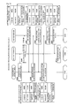
- a center-side flag that is set at transaction completed (an initial state) is set to transaction in progress (an inverted state), and thereafter a transaction-in-progress command (an inversion instruction) is transmitted to an electronic money card (step 1).
- the electronic money card receives and executes the transaction-in-progress command, and sets a terminal flag (a card-side flag) to transaction in progress. Then, it transmits a transaction-in-progress setting notice to the center server (step 2).
- the center server receives the transaction-in-progress setting notice, and thereafter sets the server flag from transaction in progress to transaction completed. Thereafter, it transmits a transaction completion command (a reset instruction) to the electronic money card (step 3).
- the electronic money card receives and executes the transaction completion command from the center server, and sets the terminal flag to transaction completed. Thereafter, it transmits a transaction completion setting notice to the center server (step 4).
- the center server receives it.
- step 2 For example, if the terminal flag is "transaction in progress” and the server flag is also "transaction in progress”, the failure has occurred in step 2.
- step 1 the terminal flag is "transaction completed” and the server flag is "transaction in progress”, and if the failure has occurred in step 4, the terminal flag and the server flag are both "transaction completed".
- the center server By configuring the center server to transmit both a command to set a flag (a transaction-in-progress command or a transaction completion command) and an arithmetic command to the electronic money card and configuring the electronic money card to perform both setting of the flag and execution of an arithmetic operation, it is made possible to update information on the electronic money card side and information on the center server side in a synchronized manner.
- a flag a transaction-in-progress command or a transaction completion command
- a transaction-in-progress command and a subtraction command are transmitted in step 1 as shown in FIG. 1(b).
- the electronic money card receives and executes the subtraction command, and thereafter transmits a subtraction completion notice (which also serves as a transaction-in-progress setting notice) to the center server in step 2.
- the center server receives the subtraction completion notice from the electronic money card, and thereafter performs subtraction from the record of balance for the electronic money card. Thereafter, processing in steps 3 and 4 is performed.
- the case where the balance of VALUE in the electronic money card becomes inconsistent with the record of balance in the center server is when a communication failure has occurred in step 2. Specifically, if the terminal flag and the server flag are both "transaction in progress", then it can be appreciated that a subtraction process has been performed in the electronic money card but no subtraction process has been performed on the record of balance on the center server side.
- step 3 the processing in steps 1 and 2 is performed, and thereafter a transaction completion command and an addition command are transmitted in step 3.
- the electronic money card receives and executes the addition command, and thereafter transmits an addition completion notice (which also serves as a transaction completion setting notice) to the center server in step 4.
- the case where the balance in the electronic money card becomes inconsistent with the record of balance in the center server is when a communication failure has occurred in step 3. Specifically, if the terminal flag is "transaction in progress" and the server flag is "transaction completed", then it can be appreciated that an addition process has been performed on the record of balance on the center server side, but no addition process has been performed in the electronic money card.
- VALUE is stored in an electronic money card, which is an IC card with a VALUE processing function, and carried by a user.
- VALUE Purchase of merchandise/services through use of VALUE can be made at affiliated stores under an agreement on business transaction by VALUE.
- the affiliated store have installed therein affiliated store terminals for accessing electronic money cards, and payment (also referred to as "settlement") can be made by subtracting the price from VALUE stored in the users' electronic money cards.
- VALUE equivalent to the amount of cash to the electronic money card.
- a process for writing VALUE to the electronic money card as such is called crediting (or charging up).
- the affiliated store terminals are classified into on-line terminals connected on-line to a center server in an electronic money center and off-line terminals for collectively transmitting log data to the center server by batch processing.
- FIG. 2 is a block diagram schematically illustrating the configuration of an electronic money system in the present embodiment.
- the electronic money system 1 is composed of a center server 2 installed in an electronic money center 100, on-line terminals 5, 5, 5, ... and off-line terminals 6 installed in affiliated stores 102, a network 4 for networking the on-line terminals 5, 5, 5, ... and the off-line terminals 6, 6, 6, ... with the center server 2, and electronic money cards 7 for performing short-range radio communication with the on-line terminals 5 and the off-line terminals 6.
- the electronic money center 100 is a business entity for managing, maintaining and controlling the electronic money system 1, and operates the center server 2 (a monetary terminal processing server).
- the center server 2 is constantly connected to the on-line terminals 5, so that it can communicate with the on-line terminals 5 in real time, and generate and transmit arithmetic commands (arithmetic instructions) in accordance with requests from the on-line terminals 5.
- center server 2 is constantly connected to the on-line terminals 5, 5, 5, ... in the present embodiment, this is not restrictive and for example, it is possible to connect the on-line terminals 5 to the center server 2 as necessary (e.g., at times when it is necessary to input various commands to the electronic money cards 7).
- the center server 2 collectively receives, for example, about once a day pieces of transaction information concerning processes performed on the electronic money cards 7 by the off-line terminals 6.
- some off-line terminals 6 are not connected to the network 4, and a person in charge in the electronic money center 100 collects storage media having stored therein pieces of transaction information from the off-line terminals 6, and inputs them to the center server 2.
- the affiliated stores 102 are stores such as convenience stores and restaurants in which merchandise or services are provided to customers and VALUE can be used as consideration for the merchandise or services.
- the affiliated stores 102 have the on-line terminals 5 and the off-line terminals 6, for example, at their cash desks, and they are used to subtract VALUE equivalent to consideration from customers' electronic money cards 7 for payment. Also, it is possible to receive cash from the customers and credit VALUE equivalent to the amount of cash to their electronic money cards 7.
- the present embodiment is based on the assumption that both payment and crediting can be performed with the on-line terminals 5, but it is also possible that only either payment or crediting is performed.
- the on-line terminal 5 is composed of a terminal computer 5a and a reader/writer 5b.
- the terminal computer 5a can be implemented by installing a predetermined computer program into a general-purpose computer provided with the reader/writer 5b or by using a dedicated machine having a dedicated module incorporated therein.
- the reader/writer 5b is a peripheral device for the terminal computer 5a, and includes an antenna for short-range radio communication with the electronic money cards 7.
- the terminal computer 5a is capable of connecting to an electronic money card 7 via the reader/writer 5b to input an arithmetic command transmitted from the center server 2 to the electronic money card 7.
- the off-line terminal 6 by itself generates an arithmetic command and inputs it to the electronic money card 7.
- the off-line terminal 6 includes the reader/writer 5b, and it processes the electronic money card 7 off-line and thereafter transmits about once a day transaction information containing a record of processing details to the center server 2 over the network 4.
- the electronic money card 7 is a monetary terminal implemented by a contactless-type IC card having a VALUE processing function incorporated therein.
- the electronic money card 7 includes an IC chip for performing the VALUE processing function and an antenna for radio communication with the reader/writer 5b.
- the electronic money card 7 has stored therein a balance amount of VALUE, and executes an addition or subtraction command inputted by the reader/writer 5b to perform addition to/subtraction from the amount of VALUE.
- FIG. 2 also shows a functional configuration of the electronic money card 7, and as shown, the electronic money card 7 includes a VALUE processing section 7a, a balance storage section 7b, a log data storage section 7c, a card ID storage section 7d, and a transaction state holding section 7e.
- the electronic money card 7 includes a VALUE processing section 7a, a balance storage section 7b, a log data storage section 7c, a card ID storage section 7d, and a transaction state holding section 7e.
- the balance storage section 7b is a storage section for storing the balance of VALUE. Upon payment or crediting, the amount of VALUE stored in the balance storage section 7b is increased or decreased.
- the balance storage section 7b constitutes a monetary information storage means for storing the amount of a monetary value as electronic data (VALUE).
- the log data storage section 7c is a storage section for storing a transaction history as log data.
- Examples of the transaction history include the date and time of transaction, ID information concerning an affiliated store terminal that has performed the transaction, classification as payment or crediting and the amount of transaction.
- transaction histories For example, up to six transaction histories can be stored, and they are sequentially erased from the oldest one.
- the card ID storage section 7d is a storage section having a card ID stored therein.
- the card ID is ID information uniquely assigned to the electronic money card 7 within the electronic money system 1, and the electronic money center 100 can identify the electronic money card 7 by the card ID. Note that the card ID is assigned to the electronic money card 7 by the electronic money center 100, but in addition to this, ID information assigned to the electronic money card 7 by the manufacturer of the electronic money card 7 may be used.
- ID information is stored in the electronic money card 7, and the ID information can be read by inputting a card ID command to the electronic money card 7.
- the transaction state holding section 7e is a storage section for storing a transaction state.
- the transaction state is flag information indicating whether or not processing on the side of the electronic money card 7 has been completed, and it constitutes a terminal flag.
- the transaction state selectively takes two value, "transaction in progress” (corresponding to the inverted state) and "transaction completed” (corresponding to the initial state).
- the transaction state holding section 7e constitutes a terminal flag storage means.
- the transaction state is set at "transaction in progress” until processing in the electronic money card 7 is completed, and it is reset to "transaction completed” upon completion of the processing.
- VALUE processing section 7a executing a transaction-in-progress command (corresponding to the inversion instruction) and a transaction completion command (corresponding to the reset instruction), which are transmitted from the center server 2.
- the VALUE processing section 7a corresponds to a flag instruction execution means.
- the transaction state stored in the transaction state holding section 7e is used for determining the time of occurrence of a failure in communication between the center server 2 and the electronic money card 7.
- the VALUE processing section 7a is an arithmetic processing section for executing various commands inputted by the reader/writer 5b, and it constitutes an arithmetic means.
- the VALUE processing section 7a When the VALUE processing section 7a receives an input of an addition command or a subtraction command, it adds/subtracts the amount attached as a parameter to the command to/from VALUE in the balance storage section 7b.
- the VALUE processing section 7a updates the transaction history in the log data storage section 7c.
- the electronic money card 7 communicates with the center server 2 via a path composed of the network 4, the terminal computer 5a and the reader/writer 5b, and the electronic money card 7 has encryption and decryption functions because the communication is encrypted.
- the network 4 is implemented by, for example, the Internet, and mediates communication between the center server 2 and the on-line terminals 5 as well as communication between the center server 2 and the off-line terminals 6.
- the network 4 may be implemented by a WAN (Wide Area Network) or a LAN (Local Area Network), and a communication link based on satellite communication, a telephone network and an optical cable network can also be used.
- WAN Wide Area Network
- LAN Local Area Network
- FIG. 3 is a block diagram schematically illustrating an exemplary hardware configuration of the electronic money card 7.
- the electronic money card 7 is a plastic card including an antenna 701 and an IC chip 702.
- a contactless-type IC card is used as the electronic money card 7, which also can be implemented by a contact-type IC card.
- the electronic money card 7 has a contact interface for accessing the IC chip 702 in place of the antenna 701.
- the affiliated store terminal also has an interface for connecting with the contact interface, and the electronic money card 7 and the affiliated store terminal communicate through the interfaces.
- the antenna 701 is an element for radio communication with the antenna included in the reader/writer 5b.
- the antenna 701 receives radio waves emitted from the reader/writer 5b, and emits radio waves toward the reader/writer 5b.
- the antenna 701 has a power generation function for generating power to drive the IC chip 702 by receiving power supply from the reader/writer 5b by radio.
- the IC chip 702 is a kind of computer including elements such as a ROM (Read Only Memory) 703, a CPU (Central Processing Unit) 704, a high-frequency circuit section 705, a RAM (Random Access Memory) 706 and a storage section 707. These elements are formed within a single IC chip.
- ROM Read Only Memory
- CPU Central Processing Unit
- RAM Random Access Memory
- the CPU 704 is a central processing unit for processing information in accordance with various programs and controlling the operation of the entire electronic money card 7.
- the ROM 703 is a read-only memory having stored therein basic programs (an OS (Operating System), a program for communicating with the reader/writer 5b, etc.) and a variety of types of data.
- OS Operating System
- a program for communicating with the reader/writer 5b, etc. a variety of types of data.
- the high-frequency circuit section 705 is an interface for communicating with the reader/writer 5b via the antenna 701.
- the CPU 704 is capable of radio communication with the reader/writer 5b via the high-frequency circuit section 705.
- the RAM 706 is a readable/writable volatile memory, which provides a working area for the CPU 704 to process various types of information. In the present embodiment, it is used, for example, when the CPU 704 executes an addition or subtraction command to increase/decrease the amount of VALUE.
- the storage section 707 is implemented by, for example, an EEPROM (Electrically Erasable and Programmable ROM), which is a non-volatile memory to/from which the CPU 704 can write/read information.
- EEPROM Electrically Erasable and Programmable ROM
- a VALUE processing program which is a program for causing the CPU 704 to function as an electronic money card 7, is stored.
- the storage section 707 has formed therein the balance storage section 7b, the log data storage section 7c, the card ID storage section 7d and the transaction state holding section 7e.
- the CPU 704 executes the VALUE processing program to implement the VALUE processing section 7a in the form of software. As a result, it is made possible to access the balance storage section 7b, the log data storage section 7c, the card ID storage section 7d and the transaction state holding section 7e to process a variety of types of information.
- the IC chip 702 and the antenna 701 are provided in the mobile terminals to enable wireless access from the reader/writer 5b as in the case of the electronic money card 7, and in addition, it is possible to allow a display device provided in the mobile terminals to display information in the IC chip 702 or it is possible to input information to the IC chip 702 via input devices of the mobile terminals.
- the present embodiment will be described with respect to the electronic money card 7, but the mobile terminals including the IC chip 702 can also be used.
- FIG. 4 is a block diagram schematically illustrating a hardware configuration of the center server 2.
- the center server 2 is composed of a control section 10 connected via a bus line 32 to an input unit 18, an output unit 20, a communication control device 24 and a storage device 30.
- the control section 10 is composed of a CPU 12, a ROM 14 and a RAM 16.
- the CPU 12 is a central processing unit for loading and executing programs stored in the ROM 14, the storage device 30 and other devices. In the present embodiment, it executes a transaction processing program stored in the storage device 30, and exercises the function as a center server 2.
- the ROM 14 is a read-only non-volatile memory having memorized therein, for example, a variety of types of programs, data and parameters for performing basic control to allow the CPU 12 to function.
- the programs in the ROM 14 are executed, for example, when the center server 2 is activated.
- the RAM 16 is a readable/writable memory used as a working memory for the CPU12, which is used, for example, when executing the transaction processing program.
- the input unit 18 is composed of, for example, input devices such as a keyboard and a mouse.
- the output unit 20 is composed of, for example, a display device implemented by a display and a printing device implemented by a printer.
- the operator of the electronic money center 100 can access the center server 2 by using the input unit 18 and the output unit 20, and perform maintenance work, program updating and other work.
- the communication control device 24 is a device for connecting the center server 2 to the network 4, which is implemented by a modem, a terminal adaptor or other connection devices.
- the communication control device 24 is controlled by the CPU 12 to transmit/receive data and other information to/from the affiliated store terminal in accordance with a predetermined protocol.
- the affiliated store terminal is the on-line terminal 5
- it is constantly connected, whereas in the case of the off-line terminal 6, connection with the off-line terminal 6 is accepted when the off-line terminal 6 performs batch processing.
- the storage device 30 is composed of a readable/writable storage medium and a drive unit for reading/writing a program or data from/to the storage medium.
- the storage medium is mainly implemented by a hard disk, but other readable/writable storage media such as a magneto-optical disk, a magnetic disk and a semiconductor memory may be used.
- the storage device 30 has formed therein a program memorization section 34 having various programs stored therein and a data memorization section 36 having a variety of types of data stored therein.
- Programs such as an OS 40, a transaction processing program 42, ... are installed in the program memorization section 34.
- the OS 40 is a program for implementing basic functions for operating the center server 2, e.g., inputting/outputting of files and control of the communication control device 24.
- the transaction processing program 42 is a program for causing the center server 2 to communicating with the electronic money card 7 via the on-line terminal 5 to perform, for example, the following processes.
- the center server 2 determines the time at which the failure has occurred based on setting statuses of the transaction states of the center server 2 and the electronic money card 7, and performs a recovery process in accordance with the time.
- the center server 2 Before performing the payment process, the crediting process and the balance confirmation process, the center server 2 checks whether or not any failure has occurred in the last processing session based on the transaction states of the center server 2 and the electronic money card 7, and if there has been any failure, recovery therefrom is made to continue the processing. As such, the center server 2 includes a recovery means.
- the data memorization section 36 is described next.
- the data memorization section 36 has stored therein a variety of types of data required for operating the center server 2, and an affiliated store terminal information database 44, a transaction information database 46, ... are stored therein.
- the affiliated store terminal information database 44 is a database having stored therein information concerning on-line terminals 5 and off-line terminals 6 installed in each affiliated store 102.
- the affiliated store terminal information database 44 has stored therein information such as affiliated store ID, terminal ID, serial ID, ..., the affiliated store ID being ID information concerning affiliated stores 102 having affiliated store terminals installed therein, the terminal ID being ID information set for on-line terminals 5 and off-line terminals 6 within the affiliated store 102, the serial ID being ID information uniquely assigned to the on-line terminals 5 and the off-line terminals 6 within the electronic money system 1.
- the center server 2 When the center server 2 receives a serial ID from an affiliated store 102, it can identify the on-line terminal 5 or off-line terminal 6 that is associated therewith, and moreover it can identify the affiliated store 102.
- the reason for assigning two types of ID information, i.e., the terminal ID and the serial ID, to identify the on-line terminal 5 and the off-line terminal 6 is to provide convenience to the affiliated store 102.
- the terminal IDs are pieces of information, which are set such as 01, 02, ..., for example, in order of installation of affiliated store terminals and therefore readily recognized by the affiliated store 102, so that the affiliated store 102 can perform management therewithin, or make inquiries at the time of malfunction, based on the terminal IDs.
- the transaction information database 46 is a database for accumulating as histories information concerning transactions performed on the electronic money card 7 via the on-line terminal 5 and the off-line terminal 6.
- the transaction information is log data generated when the electronic money card 7 is processed, and if the electronic money card 7 is processed via the on-line terminal 5, the log data is generated in real-time, whereas if the card is processed by the off-line terminal 6, the log data is temporarily accumulated in the off-line terminal 6 and thereafter transmitted to the center server 2 by batch processing, for example.
- FIG. 5 is a diagram illustrating in chronological order pieces of transaction information 61, 62 and 63 generated when an electronic money card 7 having a card ID of "00001" is processed by the on-line terminal 5.
- items such as card ID 52, balance 53, transaction amount 54, transaction state 55, processing detail 56, serial ID 57, transaction date and time 58, ... are contained in the transaction information.
- the card ID 52 is a card ID received from the electronic money card 7 via the on-line terminal 5.
- the balance 53 is a balance of VALUE after an arithmetic process has been performed in the electronic money card 7, and the transaction amount 54 is an amount that has been added or subtracted at the time of the arithmetic operation.
- the center server 2 receives the balance of VALUE from the electronic money card 7 at the time of a payment or crediting process (corresponding to a balance reception means), and acquires an arithmetic command transmission request (accompanied by the amount to add or subtract) from the on-line terminal 5 (corresponding to a request acquisition means).
- the balance 53 is calculated based on these values.
- the transaction state 55 is flag information for which either "transaction in progress” (corresponding to the inverted state) or "transaction completed” (corresponding to the initial state) is selectavely set, and it constitutes a server flag.
- the transaction state 55 is set to "transaction in progress” when processing on the side of the center server 2 is started, and updated to "transaction completed” when the processing on the side of the center server 2 is completed.
- the center server 2 includes a server flag setting means for inverting the transaction state 55 from "transaction completed” to “transaction in progress” or resetting it from "transaction in progress” to "transaction completed”.
- the third transaction information from the top of the drawing contains a transaction state 55 of "transaction in progress", and therefore it can be appreciated that processing concerning the transaction information has not been completed on the side of the center server 2.
- the serial ID 57 is a serial number of an on-line terminal 5 that serves as an interface for communicating with the electronic money card 7.
- the serial number can be checked against the affiliated store terminal information database 44 to identify the affiliated store 102 that has processed the electronic money card 7.
- the transaction date and time 58 is a date and time of communication with the on-line terminal 5. For example, a communication start time and a communication finish time are stored.
- the processing performed on the electronic money card 7 identified by a card ID 52 of "00001" is chronologically recorded as transaction information.
- the transaction information is similarly accumulated for electronic money cards 7 associated with other card IDs.
- the transaction information is recorded to the transaction information database 46 in real-time, but as for processing performed by the off-line terminal 6, there is a time lag between transmission from the off-line terminal 6 by batch processing and recording to the transaction information database 46.
- the on-line terminal 5 includes a display device for presenting information to a person in charge at the affiliated store 102 or customers having an electronic money card 7, and an audio output device for notifying a processing status by audio such as sound effects.
- FIGS. 6 through 13 flowcharts in FIGS. 6 through 13 are referenced to describe the procedure for price payment through the use of the electronic money card 7 and recovery procedures for cases where a failure has occurred during payment.
- FIG. 6 is a flowchart for explaining the procedure for performing a payment process on the electronic money card 7.
- the card information shows a logical structure of data held on the side of the electronic money card 7.
- the card information contains items such as "card ID”, "balance”, "transaction amount” and "transaction state”.
- card information 71 contains a card ID of 00001 and a balance of VALUE of 20,000 yen, and the transaction state is set at "transaction completed".
- the transaction state is set at "transaction completed"
- processing on the side of the electronic money card 7 has been completed in the last processing session.
- a customer expresses his/her intension of purchase by presenting merchandise to a person in charge (a shop clerk) at the affiliated store 102.
- the person in charge uses a barcode reader or the like to read a price of 9,000 yen for the merchandise, and inputs it as the amount of payment to the on-line terminal 5.
- a card confirmation screen as shown in FIG. 22(a) is displayed on a display device of the on-line terminal 5.
- the amount of payment is displayed along with an instruction such as "Please set electronic money card", which prompts to set the electronic money card 7 in the reader/writer 5b of the on-line terminal 5.
- the customer sets the electronic money card 7 in the on-line terminal 5 in accordance with the instruction on the card confirmation screen.
- the electronic money card 7, when set in the on-line terminal 5, is driven by radio waves from the reader/writer 5b, and starts communicating with the on-line terminal 5 (step 104).
- the center server 2 becomes capable of communicating with the electronic money card 7.
- FIG. 22(b) a communicating screen as shown in FIG. 22(b) is displayed on the display device of the on-line terminal 5.
- the customer and the person in charge at the affiliated store 102 can recognize that the electronic money card 7 and the center server 2 are attempting to communicate with each other.
- the on-line terminal 5 when the on-line terminal 5 starts communicating with the electronic money card 7, it reads a card ID from the electronic money card 7, and transmits it to the center server 2 along with the amount of payment (step 204).
- the reading of the card ID is performed by the on-line terminal 5 inputting to the electronic money card 7 a card ID command to the electronic money card 7.
- the VALUE processing section 7a executes the card ID command to read the card ID from the card ID storage section 7d, and returns it to the on-line terminal 5.
- the center server 2 When the center server 2 receives the above information from the on-line terminal 5, it issues a balance/state confirmation request to the electronic money card 7 (step 304).
- This request is intended to request the electronic money card 7 to transmit a balance of VALUE and a transaction state, and is performed by transmitting a command to cause the electronic money card 7 to perform these operations.
- the electronic money card 7 receives the balance/state confirmation request from the on-line terminal 5, and provides a balance/state confirmation response (step 106).
- the center server 2 includes a terminal flag reception means (for receiving the transaction state of the electronic money card 7).
- the center server 2 receives the balance of VALUE and the transaction state from the electronic money card 7.
- the center server 2 After checking transaction information on the sides of the electronic money card 7 and the center server 2, the center server 2 generates transaction information 81 concerning the current processing session and stores it in the transaction information database 46 for registration (step 306).
- the card ID and the balance of VALUE received from the electronic money card 7 and the transaction amount inputted by the on-line terminal 5 are contained. Note that other items such as a processing detail, a serial ID, a transaction date and time, ... are omitted in the drawing.
- the transaction information 81 contains a card ID of 00001, a post-subtraction balance of 11,000 yen and a transaction amount of 9,000 yen.
- the transaction state of the transaction information 81 is set at "transaction in progress”. As such, the transaction state is set to "transaction in progress” when processing on the side of the center server 2 is started. Then, it is set to "transaction completed” when the processing on the side of the center server 2 is completed.
- the balance in the transaction information 81 is a post-subtraction value because it is used for failure recovery, and the subtraction process on the side of the center server 2 is completed when the transaction state is set to "transaction completed".
- the center server 2 issues a transaction-in-progress subtraction request to the electronic money card 7 (step 308).
- This request is performed by transmitting to the electronic money card 7 a transaction-in-progress command and a subtraction command to execute subtraction of the amount of payment.
- both the subtraction command and the transaction-in-progress command are transmitted in order to associate execution of the subtraction command and updating of the transaction state in the electronic money card 7. Specifically, by confirming that the transaction state has been updated, it is made possible to confirm that the subtraction command has been executed in the electronic money card 7.
- both an addition command and a transaction completion command are transmitted to the electronic money card 7 in a crediting process, which will be described later.
- the electronic money card 7 receives and executes these commands, and sets the transaction state to "transaction in progress" as well as subtracting the amount of payment from the balance of VALUE.
- the card information 71 is updated to card information 72.
- the card information 72 contains a post-subtraction balance of 11,000 yen, and the transaction state is set at "transaction in progress".
- the electronic money card 7 transmits to the center server 2 a subtraction completion notice indicating that the subtraction has been completed and the transaction state has been set to "transaction in progress" (step 108).
- the center server 2 When the center server 2 receives the subtraction completion notice from the electronic money card 7, it updates the transaction information 81 to transaction information 82 by setting its transaction state to "transaction completed" (step 310).
- the center server 2 completes the subtraction process on the side of the center server 2 and establishes registration of the transaction information 82 with the transaction information database 46.
- the center server 2 When the center server 2 has completed the subtraction process on the side of the center server 2, it issues a transaction completion setting request to the electronic money card 7 (step 312). This request is performed by transmitting a transaction completion command to the electronic money card 7.
- the electronic money card 7 receives and executes the transaction completion command, and sets the transaction state to "transaction completed” (step 110). Specifically, the value of the transaction state is reset from “transaction in progress” to "transaction completed”. As a result, the card information is updated as in card information 73.
- the electronic money card 7 executes the transaction completion command, and thereafter transmits to the center server 2 a transaction completion notice indicating that the transaction state has been set to "transaction completed".
- the center server 2 Upon receipt of the transaction completion notice from the electronic money card 7, the center server 2 transmits to the on-line terminal 5 a transaction completion notice indicating that processing with the electronic money card 7 has been completed (step 314).
- the on-line terminal 5 receives the transaction completion notice from the center server 2 to confirm that the process has been completed (step 206).
- the on-line terminal 5 displays a payment completion screen as shown in FIG. 22(c) on the display device, which accompanies sound effects representing success in the process.
- the card ID and the amount of payment are displayed along with the balance of VALUE after payment.
- step 106 the parts where any failure might occur during the communication between the electronic money card 7 and the center server 2 are step 106 (referred to as "failure 1"; the same applies below), step 308 (failure 2), step 108 (failure 3), step 312 (failure 4) and step 110 (failure 5).
- step 304 processing for this case is the same as that for failure 1, and therefore the description thereof is omitted.
- FIG. 7 is a flowchart for explaining a process procedure for the case where failure 1 has occurred. Note that in the following description, steps corresponding to those in the flowchart in FIG. 6 are denoted by the same step numbers for simplification or omission of the description thereof.
- the center server 2 detects failure 1 (step 316).
- the electronic money system 1 detects the failure by timeout. Specifically, the center server 2 measures the time up to receiving a response from the electronic money card 7, and if no response is provided within a previously set predetermined period of time, it is determined that any failure has occurred. Note that this is only an example, and the failure may be detected by other methods.
- the center server 2 Upon detection of failure 1, the center server 2 transmits to the on-line terminal 5 a transaction error notice indicating that processing has failed (step 318).
- the on-line terminal 5 receives the transaction error notice from the center server 2, and confirms that the processing has failed (step 208).
- the on-line terminal 5 When the on-line terminal 5 has confirmed the processing error, it displays an error occurrence screen as shown in FIG. 22(d), which accompanies sound effects representing a transaction error.
- the electronic money system 1 requests confirmation of the balance, and makes recovery from the failure in accordance with the balance confirmation process.
- the center server 2 first checks transaction states on the sides of the center server 2 and the electronic money card 7 to check whether any failure has occurred in the last processing session. If there has been no failure, the balance is confirmed, whereas if there has been any failure, the balance is confirmed after a recovery process is performed.
- the center server 2 checks whether or not any failure has occurred in the last processing session, and if there has been any failure, recovery therefrom is made to continue the payment process or the crediting process.
- the card information 71 is left unprocessed, and it is not necessary to perform a recovery process because the transaction information has not yet been registered with the center server 2. Accordingly, when failure 1 has occurred, the balance is confirmed without performing a recovery process. Therefore, the person in charge at the affiliated store 102 confirms the balance and thereafter performs the payment process again from the beginning.
- step 308 failure 2
- step 108 failure 3
- the center server 2 detects it (step 320), and transmits a transaction error notice to the on-line terminal 5 (step 322).
- the on-line terminal 5 receives the transaction error notice to confirm the error, and displays an error occurrence screen, which accompanies sound effects (step 210).
- the card information when failure 2 has occurred, the card information is card information 71, whereas when failure 3 has occurred, it is card information 72.
- the transaction information is transaction information 81 regardless of failure 2 or 3.
- the combination of the transaction state of the card information and the transaction state of the transaction information is (transaction completed, transaction in progress) if failure 2 has occurred, and (transaction in progress, transaction in progress) if failure 3 has occurred.
- FIG. 9 is a flowchart for explaining a recovery process procedure for the case where failure 2 has occurred.
- This process is started by a person in charge at the affiliated store 102 using the on-line terminal 5 to issue a request to confirm the balance of the electronic money card 7 in accordance with an instruction on the error occurrence screen.
- the person in charge sets the electronic money card 7 in the reader/writer 5b to start communication between the electronic money card 7 and the on-line terminal 5 (step 104) (note that the electronic money card 7 is normally set in the on-line terminal 5 at the time of failure occurrence, and therefore the balance confirmation process is entered automatically), and issues a balance confirmation request to the center server 2, for example, by depressing a balance confirmation button provided on the on-line terminal 5 (step 205).
- the center server 2 receives the balance confirmation request from the on-line terminal 5, and issues a balance/state confirmation request to the electronic money card 7 (step 304), and in response to this, the electronic money card 7 provides a balance/state confirmation response (step 106).
- the center server 2 checks a combination of a transaction state transmitted in the balance/state confirmation response from the electronic money card 7 and a transaction state of transaction information 81 for the last session.
- the center server 2 determines that the last processing session has been interrupted by failure 2.
- the center server 2 performs state recovery by setting the transaction state of the transaction information 81 to "transaction recovery".
- the center server 2 is configured to consider any transaction information having its transaction state set at "transaction recovery" as invalid, and therefore transaction information 80 for the last but one session is the latest transaction information for the electronic money card 7.
- the center server 2 performs failure recovery by updating the transaction information 81 for the last session to the transaction information 80 for the last but one session (step 324).
- the center server 2 After updating the transaction information, the center server 2 transmits to the on-line terminal 5 a failure recovery notice indicating that failure recovery has been performed (step 326).
- the on-line terminal 5 receives it and confirms that recovery from the failure has been made (step 212).
- the failure recovery notice the balance of VALUE in the electronic money card 7 is transmitted, and the on-line terminal 5 displays the balance of VALUE. That is, the failure recovery is performed along with the confirmation of the balance.
- the person in charge at the affiliated store 102 confirms the balance, and thereafter performs the payment process again from the beginning.
- FIG. 10 is a flowchart for explaining a recovery process procedure for the case where failure 3 has occurred.
- Steps 104 through 106 are the same as those for failure 2.
- the center server 2 checks a combination of the transaction state transmitted from the electronic money card 7 and the transaction state of the transaction information 81 for the last session to find that the combination of the transaction states is (transaction in progress, transaction in progress), and it determines that the last processing session has been interrupted by failure 3 because the last transaction was a payment process.
- the center server 2 If failure 3 has occurred, the center server 2 generates an addition command to add the amount that has been subtracted from the electronic money card 7 in the last session, and transmits it to the electronic money card 7 along with a transaction completion command (step 328).
- the electronic money card 7 executes the addition command to add VALUE equivalent to the amount that has been subtracted in the last session, and sets the transaction state to "transaction completed”. Then, it transmits to the center server 2 an addition completion notice indicating the addition process and the setting to "transaction completed" (step 112).
- the above processing updates the card information from the card information 72 to the card information 71.
- the center server 2 Upon receipt of the addition completion notice from the electronic money card 7, the center server 2 sets the transaction state of the transaction information 81 to "transaction recovery" as in the case of failure 2 to update the transaction information (step 330). As a result, the transaction information 80 for the last but one session is considered as the latest transaction information.
- the center server 2 transmits a failure recovery notice to the on-line terminal 5 (step 332), and based on this, the on-line terminal 5 confirms that recovery from the failure has been made (step 214).
- the VALUE that has been subtracted at the time of failure occurrence is added to the electronic money card 7 to restore the balance of VALUE to the state it was in before the occurrence of failure, and also to restore the transaction information to the state it was in before the occurrence of failure.
- the subtraction is executed in the electronic money card 7 before the transaction information is established in the center server 2 (before the transaction information is updated to post-payment transaction information), and therefore it is possible to recover the state before the occurrence of failure by returning the subtracted VALUE to the electronic money card 7.
- FIG. 11 is a flowchart for explaining a process procedure for cases where failures 4 and 5 have occurred.
- Steps 104 through 310 are the same as those in the flowchart in FIG. 6.
- the center server 2 updates the transaction information to the transaction information 82 (step 310), and thereafter transmits a transaction completion command to the electronic money card 7 (step 312).
- the center server 2 detects that either of the failures has occurred (step 334), and issues a transaction error notice to the on-line terminal 5 (step 336).
- the on-line terminal 5 displays an error occurrence screen on the display device, which accompanies sound effects representing a transaction processing error (step 216).
- the card information is card information 72, whereas when failure 5 has occurred, it is card information 73.
- the transaction information is transaction information 82.
- the combination of the transaction states is (transaction in progress, transaction completed) in the case of failure 4, and (transaction completed, transaction completed) in the case of failure 5.
- FIG. 12 is a flowchart for explaining a recovery process procedure for the case where failure 4 has occurred.
- Steps 104 through 106 are the same as those in the case of failure 2.
- the center server 2 checks a combination of a transaction state transmitted from the electronic money card 7 and a transaction state of transaction information 82 for the last session to find that the combination of the transaction states is (transaction in progress, transaction completed), and because the last transaction was a payment process, it is determined that the last processing session has been interrupted by failure 4.
- the center server 2 issues a transaction completion setting request to the electronic money card 7 (step 338).
- the transaction completion setting request is performed by transmitting a transaction completion command to the electronic money card 7.
- the electronic money card 7 receives and executes the transaction completion command, and sets the transaction state of the card information 72 to "transaction completed". As a result, the card information is updated from the card information 72 to the card information 73.
- the electronic money card 7 transmits a transaction completion notice to the center server 2 (step 114).
- the center server 2 After receiving the transaction completion notice, the center server 2 transmits a failure recovery notice to the on-line terminal 5 (step 340), and the on-line terminal 5 receives it and confirms that the recovery from failure 4 has been made (step 218).
- FIG. 13 is a flowchart for explaining a recovery process procedure for the case where failure 5 has occurred.
- Steps 104 through 106 are the same as those in the case of failure 2.
- the center server 2 checks a combination of a transaction state transmitted from the electronic money card 7 and a transaction state of transaction information 82 for the last session to find that the combination of the transaction states is (transaction completed, transaction completed), and because the last transaction was a payment process, it is determined that the last processing has been interrupted by failure 5.
- the center server 2 transmits a failure recovery notice to the on-line terminal 5 without performing any particular recovery process (step 342), and based on this, the on-line terminal 5 confirms that recovery from the failure has been made (step 220).
- FIGS. 14 through 20 flowcharts in FIGS. 14 through 20 are referenced to describe the procedure for a crediting process through the use of the electronic money card 7 and the recovery procedure for the case where any failure has occurred during crediting.
- FIG. 14 is a flowchart for explaining the procedure for a crediting process.
- the customer first hands 9,000 yen in cash to a person in charge at the affiliated store 102 to ask for crediting of 9,000 yen.
- the person in charge receives 9,000 yen from the customer, and inputs 9,000 yen as the amount of crediting to the on-line terminal 5.
- a card confirmation screen is displayed on the display device of the on-line terminal 5, and the customer sets the electronic money card 7 in the reader/writer 5b in accordance with an instruction on the screen.
- the electronic money card 7, when set in the on-line terminal 5, is driven by radio waves emitted from the reader/writer 5b in the on-line terminal 5 to start communicating with the on-line terminal 5 (step 504).
- the center server 2 When the electronic money card 7 is connected to the on-line terminal 5, the center server 2 becomes capable of communicating with the electronic money card 7, and a communicating screen is displayed on the display device of the on-line terminal 5.
- the on-line terminal 5 When the on-line terminal 5 starts communicating with the electronic money card 7, it reads a card ID from the electronic money card 7 and transmits it to the center server 2 along with the amount of crediting (step 604).
- the center server 2 Upon receipt of these pieces of information, the center server 2 issues a balance/state confirmation request to the electronic money card 7 (step 704).
- the electronic money card 7 receives it and provides a balance/state confirmation response (step 506).
- the center server 2 Upon receipt of the balance/state confirmation response from the electronic money card 7, the center server 2 checks whether any failure has occurred in the last processing session, and if there has been any failure, recovery therefrom is made to continue the process. The failure recovery process will be described later, and here it is assumed that there has been no failure.
- the center server 2 After confirming that there has been no failure in the last processing session, the center server 2 generates transaction information 86 concerning the processing and registers it with the transaction information database 46 (step 706).
- the transaction information 86 contains a post-crediting balance, but the transaction state is set at "transaction in progress" and registration with the transaction information database 46 has not been established. That is, the center server 2 has not yet completed an addition process.
- the center server 2 issues a transaction-in-progress setting request to the electronic money card 7 (step 708).
- the electronic money card 7 Upon receipt of the transaction-in-progress setting request, the electronic money card 7 sets the transaction state to "transaction in progress", and transmits a transaction-in-progress setting notice to the center server 2 (step 508). As a result, card information 76 is updated to card information 77.
- the center server 2 Upon receipt of the transaction-in-progress setting notice from the electronic money card 7, the center server 2 sets the transaction state to "transaction completed", thereby updating the transaction information 86 to transaction information 87 (step 710).
- the center server 2 issues a transaction completion setting/addition request to the electronic money card 7 (step 714). This is performed by transmitting both an addition command to add the amount of crediting and a transaction completion command to the electronic money card 7.
- the electronic money card 7 receives these commands and executes the addition command to increase the balance of VALUE by 9,000, and it also sets the transaction state to "transaction completed”. Then, it transmits an addition completion notice indicating the addition process and the setting to "transaction completed" to the center server 2 (step 510).
- the execution of the addition command and the transaction completion command updates the card information 77 to card information 78.
- the card information 78 contains a balance of VALUE of 29,000 yen and has its transaction state set at "transaction completed".
- the center server 2 Upon receipt of the addition completion notice from the electronic money card 7, the center server 2 transmits a transaction completion notice to the on-line terminal 5 (step 716).
- the on-line terminal 5 receives the transaction completion notice from the center server 2 to confirm that the process has been completed (step 606).
- the on-line terminal 5 displays a crediting completion screen on the display device, which accompanies sound effects representing success in the process.
- step 506 (failure 6), step 708 (failure 7), step 508 (failure 8), step 714 (failure 9) and step 510 (failure 10).
- step 704 processing for this case is the same as that for failure 6, and therefore the description thereof is omitted.
- FIG. 15 is a flowchart for explaining a process procedure for the case where failure 6 has occurred.
- steps corresponding to those in the flowchart in FIG. 15 are denoted by the same step numbers for simplification or omission of the description thereof.
- failure 6 has occurred when the electronic money card 7 transmits a balance of VALUE and a transaction state to the center server 2 (step 506)
- the center server 2 detects failure 6 (step 718).
- the center server 2 Upon detection of failure 6, the center server 2 transmits to the on-line terminal 5 a transaction error notice indicating that a transaction process has failed (step 720).
- the on-line terminal 5 receives the transaction error notice from the center server 2 to confirm that the processing has failed (step 608).
- the on-line terminal 5 displays an error occurrence screen, which accompanies sound effects representing a transaction failure.
- the error occurrence screen gives a notice instructing to confirm the balance, with the result that a person in charge at the affiliated store 102 performs a balance confirmation process for the electronic money card 7.
- FIG. 16 is a flowchart for explaining a process procedure for cases where failures 7 and 8 have occurred.
- step 708 If any failure has occurred in step 708 (failure 7) or step 508 (failure 8), the center server 2 detects it (step 718) and transmits a transaction error notice to the on-line terminal 5 (step 720).
- the on-line terminal 5 receives the transaction error notice to confirm the error, and displays an error occurrence screen, which accompanies sound effects (step 608).
- the card information when failure 7 has occurred, the card information is card information 76, whereas when failure 8 has occurred, it is card information 77.
- the transaction information is transaction information 86 regardless of failure 7 or 8.
- the combination of the transaction state of the card information and the transaction state of the transaction information is (transaction completed, transaction in progress) if failure 7 has occurred, and (transaction in progress, transaction in progress) if failure 8 has occurred.
- FIG. 17 is a flowchart for explaining a recovery process procedure for the case where failure 7 has occurred.
- This process is started by a person in charge at the affiliated store 102 using the on-line terminal 5 to issue a request to confirm the balance of the electronic money card 7 in accordance with an instruction on an error occurrence screen.
- the person in charge sets the electronic money card 7 in the reader/writer 5b to start communication between the electronic money card 7 and the on-line terminal 5 (step 504) (note that the electronic money card 7 is normally set in the on-line terminal 5 at the time of failure occurrence, and therefore the balance confirmation process is entered automatically), and issues a balance confirmation request to the center server 2, for example, by depressing a balance confirmation button provided on the on-line terminal 5 (step 605).
- the center server 2 receives the balance confirmation request from the on-line terminal 5, and issues a balance/state confirmation request to the electronic money card 7 (step 704), and in response to this, the electronic money card 7 provides a balance/state confirmation response (step 506).
- the center server 2 checks a combination of a transaction state transmitted in the balance/state confirmation response from the electronic money card 7 and a transaction state of transaction information 86 for the last session.
- the center server 2 sets the transaction state of the transaction information 86 to "transaction recovery" to update the transaction information 86 to transaction information 88.
- the center server 2 considers any transaction information having its transaction state set at "transaction recovery" as invalid, and therefore transaction information 85 for the last but one session is revived as the latest transaction information.
- the center server 2 performs failure recovery by updating the transaction information 86 for the last session to the transaction information 85 for the last but one session (step 722).
- the center server 2 After updating the transaction information, the center server 2 transmits to the on-line terminal 5 a failure recovery notice indicating that failure recovery has been performed (step 724).
- the on-line terminal 5 receives it and confirms that recovery from the failure has been made (step 610).
- the person in charge at the affiliated store 102 confirms the balance, and thereafter performs the crediting process again from the beginning.
- FIG. 18 is a flowchart for explaining a recovery process procedure for the case where failure 8 has occurred.
- Steps 504 through 506 are the same as those for failure 7.
- the center server 2 checks a combination of a transaction state transmitted from the electronic money card 7 and a transaction state of the transaction information 86 for the last session to find that the combination of the transaction states is (transaction in progress, transaction in progress), and because the last transaction was a crediting process, it is determined that the last processing session has been interrupted by failure 8.
- failure recovery should be performed by restoring the card information and the transaction information to the state they were in before the crediting process.
- the center server 2 issues a transaction completion setting request to the electronic money card 7 (step 726). This request is performed by transmitting a transaction completion command to the electronic money card 7.
- the electronic money card 7 sets the transaction state to "transaction completed”, and transmits a transaction completion setting notice to the center server 2 (step 512).
- the card information is restored from card information 77 to card information 76.
- the center server 2 Upon receipt of the transaction completion notice from the electronic money card 7, the center server 2 sets the transaction state of the transaction information 86 to "transaction recovery" to update it to transaction information 88 (step 728). As a result, the transaction information 88 becomes invalid transaction information, and transaction information 85 for the last but one session is revived as the latest transaction information.
- the center server 2 transmits a process recovery notice to the on-line terminal 5 (step 730), and based on this, the on-line terminal 5 confirms that recovery from the failure has been made (step 612).
- FIG. 19 is a flowchart for explaining process procedures for cases where failures 9 and 10 have occurred.
- Steps 504 through 710 are the same as those in the flowchart in FIG. 14.
- the center server 2 updates the transaction information to transaction information 87 (step 714), and thereafter transmits a transaction completion command and an addition command to the electronic money card 7 (step 714).
- the center server 2 detects any one of these failures has occurred (step 732), and issues a transaction error notice to the on-line terminal 5 (step 734).
- the on-line terminal 5 displays an error occurrence screen on the display device, which accompanies sound effects representing a transaction processing error (step 614).
- the card information is card information 77, whereas when failure 10 has occurred, it is card information 78.
- the transaction information is transaction information 87.
- the combination of the transaction states is (transaction in progress, transaction completed) in the case of failure 9, and (transaction completed, transaction completed) in the case of failure 10.
- FIG. 20 is a flowchart for explaining a recovery process procedure for the case where failure 9 has occurred.
- Steps 504 through 606 are the same as those in the case of failure 6.
- the center server 2 checks a combination of a transaction state transmitted from the electronic money card 7 and a transaction state of transaction information 87 for the last session to find that the combination of the transaction states is (transaction in progress, transaction completed), and because the last transaction was a crediting process, it is determined that the last processing session has been interrupted by failure 9.
- the center server 2 reissues a transaction completion setting/addition request to the electronic money card 7 (step 736).
- the electronic money card 7 performs an addition process as well as setting the transaction state to "transaction completed", and it transmits an addition completion notice to the center server 2 (step 514).
- card information 77 is updated to card information 78.
- the center server 2 After receiving the addition completion notice, the center server 2 transmits a failure recovery notice to the on-line terminal 5 (step 738), and the on-line terminal 5 receives it and confirms that recovery from failure 9 has been made (step 616).
- failure 10 because both the electronic money card 7 and the center server 2 have completed the addition process and their transaction states are both set at "transaction completed", it is not necessary to perform a state recovery process.
- the electronic money card 7 is never processed by a subtraction process, and therefore the customer can use the electronic money card 7 with a sense of security.
- failure recovery is performed in conjunction with balance confirmation, but the failure recovery might not be performed if neither the customer nor the person in charge at the affiliated store 102 is aware of occurrence of failure.
- the center server 2 checks whether or not any failure has occurred in the last processing session, and therefore, even if failure recovery has not been performed in the last transaction, it is possible to perform the process after performing failure recovery in the current transaction.
- nonrecovered card an electronic money card 7 on which failure recovery has not been performed
- the center server 2 performs failure recovery based on transaction information, and therefore after using the nonrecovered card with the off-line terminal 6 for payment, it is still possible to set this card with an outstanding balance in the on-line terminal 5 to perform failure recovery.
- an upper limit is set for the balance of VALUE that can be stored in the electronic money card 7, and therefore if the nonrecovered card is credited, the balance of VALUE might exceed the upper limit.
- VALUE the upper limit for VALUE is fifty thousand yen. Further, it is assumed that the VALUE that is currently stored in the nonrecovered card is forty thousand yen, but five thousand yen will be added by making recovery from a failure.
- the off-line terminal 6 checks whether or not the electronic money card 7 is a nonrecovered card before crediting the electronic money card 7, and limits crediting if it is a nonrecovered card.
- FIG. 21 is a flowchart for explaining the procedure for crediting the electronic money card 7 via the off-line terminal 6. Note that the off-line terminal 6 constitutes an arithmetic instruction input unit as described below.
- a person in charge at the affiliated store 102 inputs the amount of crediting to the off-line terminal 6 (step 904). This corresponds to an addition amount acquisition means.
- the off ⁇ line terminal 6 issues a balance/state confirmation request to the electronic money card 7 (step 906), and in response to this, the electronic money card 7 provides a balance/state confirmation response to the off-line terminal 6 (step 804).
- the center server 2 receives a transaction state from the electronic money card 7, which corresponds to a terminal flag reception means.
- the off-line terminal 6 determines whether the transaction state received from the electronic money card 7 is "transaction completed” or "transaction in progress "(step 908).
- step 908 If the transaction state is "transaction completed" (step 908; Y), the off-line terminal 6 generates an addition command and inputs it to the electronic money card 7 to perform a crediting process (step 806).
- step 1000 the off-line terminal 6 sounds an alarm without performing a crediting process.
- Such an off-line terminal 6 includes an addition instruction generation means and an addition instruction input means for limiting input to the electronic money card 7 when the transaction state is "transaction in progress".
- the off-line terminal 6 is capable of determining whether or not the electronic money card 7 is a nonrecovered card by checking the transaction state of the electronic money card 7, and if it is a nonrecovered card, limits the crediting process (in the present embodiment, the crediting process is not allowed at all).
- the case where the balance of VALUE stored in the electronic money card 7 becomes less than the balance of VALUE that is actually owned by the user due to a failure is when failure 3 or 9 has occurred.
- the off-line terminal 6 it is possible for the off-line terminal 6 to dynamically limit the upper bound of the amount that can be credited, allowing for the amount that might be added by failure recovery.
- the added amount is equivalent to the amount recorded in "transaction amount".
- the amount may be added to or subtracted from the balance of VALUE depending on the types of failures, the off-line terminal 6 can recognize at least that there is a possibility that the balance is added with the amount that may be added.
- the off-line terminal 6 sets the amount that is obtained by subtracting the above amount from the upper limit as the upper limit for the electronic money card 7.
- the center server 2 transmits a transaction-in-progress command in step 1, and receives a transaction-in-progress setting notice in step 2, and moreover it transmits a transaction completion command in step 3, and receives a transaction completion notice in step 4.
- the times to transmit an arithmetic instruction to the electronic money card 7 are steps 1 and 3, and FIG. 23(a) shows the case where an arithmetic command is transmitted in step 1.
- step 2 or 3 the transaction state of the electronic money card 7 is "transaction in progress". That is, as long as it is known that the transaction state of the electronic money card 7 is "transaction in progress", it is possible to know that the failure has occurred after an arithmetic process has been performed in the electronic money card 7. Therefore, it is not always necessary to distinguish between steps 2 and 3.
- step 1 when the transaction state of the electronic money card 7 is "transaction completed", it is not possible to identify whether the failure has occurred before the arithmetic process (step 1) or the failure has occurred after the arithmetic process (step 4). Therefore, the transaction state of the center server 2 is inverted (odd number of times) between steps 1 and 4, making it possible to discriminate between a failure in step 1 and a failure in step 4.
- inverting the transaction state means setting the transaction state such as "transaction completed” -> “transaction in progress”, or "transaction in progress” -> “transaction completed”.
- FIG. 23(b) shows the case where an arithmetic command is transmitted in step 3.
- the transaction information of the electronic money card 7 is "transaction in progress"
- step 1 when the transaction information is "transaction completed", it is not possible to identify, based only on this, whether the failure has occurred before the arithmetic process (step 1) or the failure has occurred after the arithmetic process (step 4). Therefore, the transaction state on the side of the center server 2 is inverted between steps 1 and 4, making it possible to identify when the failure has occurred. Also, the balance of VALUE stored on the side of the center server 2 is updated at the time of inversion.
- an arithmetic command may be transmitted simultaneously when setting the transaction state of the electronic money card 7 to "transaction in progress" or "transaction completed", the transaction state of the center server 2 may be inverted after transmitting a transaction-in-progress command to the electronic money card 7 (step 1) but before receiving a transaction completion notice (step 4), and in addition, the balance of VALUE stored on the side of the center server 2 may be updated at the time of inversion.
- the center server 2 may transmit a transaction-in-progress command to invert the transaction state of the electronic money card 7. After confirming that the electronic money card 7 has executed it and the transaction state has been inverted to "transaction in progress", a transaction completion command may be transmitted to the electronic money card 7 to reset the transaction state of the electronic money card 7 to "transaction completed”. An arithmetic command may be transmitted simultaneously when the transaction-in-progress command or the transaction completion command is transmitted.
- the transaction state of the center server 2 may be inverted or reset, and at the same time, a balance update may be established in the center server 2.
- the on-line terminal 5 may be implemented by a personal computer capable of connecting to the Internet, which is installed in the customer's home. In such a case, even if the customer visits the affiliated store 102 without being aware that a failure has occurred during processing of the electronic money card 7 via communication at his/her home, it is still possible to recover from the failure by using the on-line terminal 5.
- the center server 2 transmits an addition command or a subtraction command to the electronic money card 7 and the electronic money card 7 executes the command to update the balance stored therein, but it is also possible that an arithmetic operation on the balance is performed in the center server 2.
- the center server 2 acquires the balance stored in the electronic money card 7 from the electronic money card 7, and performs an addition/subtraction process thereon to calculate the amount after the addition/subtraction process.
- the center server 2 transmits the calculated amount to the electronic money card 7, and the electronic money card 7 updates the balance stored therein to the amount received from the center server 2.
- the addition/subtraction process may be performed in the center server 2 or the electronic money card 7, or it is possible that the center server 2 performs one of the addition and subtraction operations and the electronic money card 7 performs the other operation, such that the addition is performed in the center server 2 and the subtraction is performed in the electronic money card 7.
- the addition/subtraction command constitutes amount change information.
- the electronic money card 7 updates the amount based on a post-addition/subtraction amount calculated by the center server 2
- the post-addition/subtraction amount transmitted to the electronic money card 7 by the center server 2 corresponds to the amount change information.
- the VALUE processing section 7a constitutes an amount change means for performing an amount change process on the balance amount, based on the amount change information.
- the center server 2 includes an amount change information transmission means for transmitting amount change information such as an arithmetic command or a post-arithmetic amount.
- the off-line terminal 6 constitutes an amount change information input unit.
- the off-line terminal 6 acquires the amount of crediting in step 904, which constitutes an increase amount acquisition means for acquiring an increase amount.
- step 806 which constitutes an amount change information generation means for generating amount change information for yielding an increase of the monetary value corresponding to an inputted increase amount.
- the off-line terminal 6 includes an amount change information input means for, if the transaction state of the electronic money card 7 is "transaction completed", inputting generated amount change information to the electronic money card 7 and, if "transaction in progress", limiting input of the amount change information.
Abstract
Description
- The present invention relates to a monetary terminal processing server, a monetary terminal processing method, a monetary terminal, an arithmetic instruction input unit and an amount change information input unit, which process electronic money stored in an IC card, for example.
- Following the success of a large-scale practical application test for electronic money (electronic cash) performed in recent years with support from general retailers and consumers, our country is entering the age of electronic money.
- In electronic money systems currently in practical use, the amount of a monetary value is stored in an electronic money card implemented with a contactless-type IC card, for example.
- The electronic money card includes a CPU (Central Processing Unit), which can be caused to execute an addition or subtraction command inputted thereto (hereinafter, the "arithmetic command"), thereby increasing/decreasing the amount of the monetary value in the card. The monetary value in the card is represented by electronic information called "VALUE".
- Business entities that accept electronic money in exchange for providing merchandise/services are registered with an organizer of an electronic money system (hereinafter, the "electronic money center") to become affiliated stores, and they have transaction terminals for accessing electronic money cards. Instead of cash payments, the affiliated stores carry out business transactions by using the transaction terminals to increase/decrease the balance of VALUE in customers' electronic money cards.
- The transaction terminals are classified into on-line terminals connected on-line to a server device (a center server) at the electronic money center and off-line terminals connected to the center server by batch processing several times a day.
- For example, the on-line terminals are used in a network environment capable of high-speed communication, e.g., broadband communication, whereas the off-line terminals are used where high-speed communication is not available.
- When the electronic money systems were first put to practical use, the off-line terminals were used as transaction terminals, but because of the progress of broadband networks, they are now being gradually replaced with the on-line terminals. However, there are still locations where the on-line terminals are difficult to install, and therefore the off·line terminals and the on-line terminals coexist in current electronic money systems.
- The on-line terminals serve as a communication interface between electronic money cards and the center server, which allows the center server to transmit predetermined arithmetic instructions to the electronic money cards. The electronic money cards execute the arithmetic instructions to increase/decrease the amount of VALUE therein.
- On the other hand, the off-line terminals input arithmetic commands to electronic money cards off-line, thereby increasing/decreasing the amount of VALUE in the cards, and accumulate information concerning the transactions as log data. They are collectively transmitted to the center server by batch processing several times a day.
- The electronic money center aggregates information concerning transactions with the on-line terminals and transaction information received from the off-line terminals, and transfers cash to the affiliated stores' bank accounts based on the aggregation results.
- In this manner, the electronic money center uses the transaction information to associate transfer of exchangeable values in VALUE with actual cash.
- Technologies using the electronic money as such include the following.
- Patent Document 1:
Japanese Laid-Open Patent Publication No. 2003-141428 - In this technology, a monetary value is stored in contactless-type IC cards carried by users, and the value is increased/decreased to circulate electronic money.
- In the case of the off-line terminal, it is almost not necessary to consider the possibility that any failure might occur while processing the electronic money card because the processing is completed by communication between the off-line terminal and the electronic money card, which takes only a short period of time (e.g., about 0.1 seconds), and in addition, the communication path is short.
- In the case of using the on-line terminal, however, it is necessary to consider the possibility that any failure might occur while processing the electronic money card because the electronic money card and the center server communicate with each other, which increases the communication time (e.g., about 1 second), and the communication path is a complicated and long distance one.
- In addition, if any failure occurs and an attempt needs to be made to recover therefrom, the balance of VALUE in the electronic money card might become inconsistent with the balance of VALUE recorded in the center server because the on-line terminals and the off-line terminals coexist (although information in the electronic money card is always the latest one, information at the center server is not updated to the latest state until information from all off-line terminals is received), and therefore it is not possible to perform a recovery process based on the balance of VALUE.
- Further, from the viewpoint of ensuring users' convenience, it is necessary to construct a recovery system such that, when the balance of VALUE becomes inconsistent between the center server and the electronic money card due to occurrence of a failure and an attempt needs to be made to recover therefrom, modification to the balance of VALUE in the user's electronic money card is at least not a subtraction process (i.e., the balance of VALUE in the electronic money card does not change or addition is made thereto).
- Therefore, an object of the present invention is to provide a monetary terminal processing server, a monetary terminal processing method, a monetary terminal, an arithmetic instruction input unit and an amount change information input unit, which are capable of properly performing failure recovery in an electronic money system using on-line terminals.
- In order to attain the above object, the invention claimed in
claim 1 of the present invention provides a monetary information processing server used in a monetary information processing system composed of a monetary terminal for storing monetary information representing a balance amount of a monetary value as electronic data, executing a predetermined arithmetic instruction to perform an arithmetic process on the balance amount, and storing a terminal flag selectable between an initial state and an inverted state, and the monetary information processing server for communicating with the monetary terminal, the server comprising: balance reception means for receiving the balance amount from the monetary terminal; request acquisition means for acquiring an arithmetic instruction transmission request to the monetary terminal; terminal flag setting means for transmitting to the monetary terminal an inversion instruction to invert the terminal flag to the inverted state, and for, after confirming that the terminal flag has been inverted to the inverted state in the monetary terminal, transmitting a reset instruction to reset the terminal flag to the initial state; arithmetic instruction transmission means for, when the inversion instruction or the reset instruction is transmitted to the monetary terminal, transmitting the arithmetic instruction; server flag setting means for inverting or resetting a server flag in a period since the inversion instruction has been transmitted to the monetary terminal until the terminal flag is confirmed as having been reset; and balance updating means for updating the received balance amount as the server flag is inverted or reset. - The invention claimed in
claim 2 provides the monetary terminal processing server according toclaim 1, comprising: terminal flag reception means for, when a failure has occurred during communication with the monetary terminal, receiving a state of the terminal flag set in the monetary terminal at the time of occurrence of the failure; and recovery means for determining whether the failure has occurred before or after the arithmetic process has been executed in the monetary terminal, based on the received state of the terminal flag and the server flag set at the time of occurrence of the failure, and performing a recovery process for the failure in accordance with the determination. - The invention claimed in
claim 3 provides the monetary terminal processing server according toclaim 2, wherein when a subtraction instruction is transmitted as the arithmetic instruction, the balance updating means updates the balance amount after confirming that the subtraction instruction has been executed in the monetary terminal, and when an addition instruction is transmitted as the arithmetic instruction, the arithmetic instruction transmission means transmits the addition instruction after the balance amount has been updated, and wherein when determined that the failure has occurred after the subtraction instruction has been executed in the monetary terminal but before the balance amount is updated, the recovery means performs the recovery process by adding an amount corresponding to the subtraction to the monetary terminal, and when determined that the failure has occurred after the balance amount has been updated but before the addition instruction is executed in the monetary terminal, the recovery means performs the recovery process by adding an amount corresponding to the update to the monetary terminal. - The invention claimed in
claim 4 provides a monetary information processing method performed by a monetary information processing server used in a monetary information processing system composed of a monetary terminal for storing monetary information representing a balance amount of a monetary value as electronic data, executing a predetermined arithmetic instruction to perform an arithmetic process on the balance amount, and storing a terminal flag selectable between an initial state and an inverted state, and the monetary information processing server for communicating with the monetary terminal, wherein the monetary information processing server includes balance reception means, request acquisition means, terminal flag setting means, arithmetic instruction transmission means, server flag setting means and balance updating means, and wherein the method comprises: a balance reception step performed by the balance reception means for receiving the balance amount from the monetary terminal; a request acquisition step performed by the request acquisition means for acquiring an arithmetic instruction transmission request to the monetary terminal; a terminal flag setting step performed by the terminal flag setting means for transmitting to the monetary terminal an inversion instruction to invert the terminal flag to the inverted state, and for, after confirming that the terminal flag has been inverted to the inverted state in the monetary terminal, transmitting a reset instruction to reset the terminal flag to the initial state; an arithmetic instruction transmission step performed by the arithmetic instruction transmission means for, when the inversion instruction or the reset instruction is transmitted to the monetary terminal, transmitting the arithmetic instruction; a server flag setting step performed by the server flag setting means for inverting or resetting a server flag in a period since the inversion instruction has been transmitted to the monetary terminal until the terminal flag is confirmed as having been reset; and a balance updating step performed by the balance updating means for updating the received balance amount as the server flag is inverted or reset. - The invention claimed in
claim 5 provides a monetary terminal, wherein a monetary terminal processing server ofclaim 1 transmits an arithmetic instruction, the terminal comprising: monetary information storage means for storing monetary information representing a balance amount of a monetary value as electronic data; arithmetic means for performing an arithmetic process on the balance amount by executing a predetermined arithmetic instruction; terminal flag storage means for holding a terminal flag selectable between an initial state and an inverted state; and flag instruction execution means for executing an inversion instruction transmitted from the monetary terminal processing server to set the stored terminal flag from the initial state to the inverted state, and executing a reset instruction transmitted from the monetary terminal processing server to reset the stored terminal flag from the inverted state to the initial state. - The invention claimed in
claim 6 provides an arithmetic instruction input unit for inputting the addition instruction to a monetary terminal ofclaim 5, comprising: addition amount acquisition means for acquiring an addition amount; addition instruction generation means for generating an addition instruction to add a monetary value equivalent to the acquired addition amount; terminal flag reception means for receiving a terminal flag stored in the terminal flag storage means from the monetary terminal; and addition instruction input means for, when the terminal flag is in an initial state, inputting the generated addition instruction to the monetary terminal, and when the terminal flag is in an inverted state, limiting input of the addition instruction to the monetary terminal. - The invention claimed in
claim 7 provides a monetary information processing server used in a monetary information processing system composed of a monetary terminal for storing monetary information representing a balance amount of a monetary value as electronic data, performing an amount change process on the balance amount based on predetermined amount change information, and storing a terminal flag selectable between an initial state and an inverted state, and the monetary information processing server for communicating with the monetary terminal, the server comprising: balance reception means for receiving the balance amount from the monetary terminal; request acquisition means for acquiring an amount change information transmission request to the monetary terminal; terminal flag setting means for transmitting to the monetary terminal an inversion instruction to invert the terminal flag to the inverted state, and after confirming that the terminal flag has been inverted to the inverted state in the monetary terminal, transmitting a reset instruction to reset the terminal flag to the initial state; amount change information transmission means for, when the inversion instruction or the reset instruction is transmitted to the monetary terminal, transmitting amount change information requested by the acquired transmission request; server flag setting means for inverting or resetting a server flag in a period since the inversion instruction has been transmitted to the monetary terminal until the terminal flag is confirmed as having been reset; and balance updating means for updating the received balance amount as the server flag is inverted or reset. - The invention claimed in
claim 8 provides the monetary terminal processing server according toclaim 7, comprising: terminal flag reception means for, when a failure has occurred during communication with the monetary terminal, receiving a state of the terminal flag set in the monetary terminal at the time of occurrence of the failure; and recovery means for determining whether the failure has occurred before or after the amount change process has been executed in the monetary terminal, based on the received state of the terminal flag and the server flag set at the time of occurrence of the failure, and performing a recovery process for the failure in accordance with the determination. - The invention claimed in
claim 9 provides the monetary terminal processing server according toclaim 8, wherein when amount change information for decrease is transmitted as the amount change information, the balance updating means updates the balance amount after confirming that the amount change process has been executed in the monetary terminal, and when amount change information for addition is transmitted as the amount change information, the amount change information transmission means transmits the amount change information after the balance amount has been updated, and wherein when determined that a failure has occurred after an amount change process for decrease has been executed in the monetary terminal but before the balance amount is updated, the recovery means performs the recovery process by adding an amount corresponding to the decrease to the monetary terminal, and when determined that a failure has occurred after the balance amount has been updated but before an amount change process for increase is executed in the monetary terminal, the recovery means performs the recovery process by adding an amount corresponding to the update to the monetary terminal. - The invention claimed in
claim 10 provides an information processing method performed by a monetary information processing server used in a monetary information processing system composed of a monetary terminal for storing monetary information representing a balance amount of a monetary value as electronic data, performing an amount change process on the balance amount based on predetermined amount change information, and storing a terminal flag selectable between an initial state and an inverted state, and the monetary information processing server for communicating with the monetary terminal, wherein the monetary information processing server includes balance reception means, request acquisition means, terminal flag setting means, amount change information transmission means, server flag setting means and balance updating means, and wherein the method comprises: a balance reception step performed by the balance reception means for receiving the balance amount from the monetary terminal; a request acquisition step performed by the request acquisition means for acquiring amount change information transmission request to the monetary terminal; a terminal flag setting step performed by the terminal flag setting means for transmitting to the monetary terminal an inversion instruction to invert the terminal flag to the inverted state, and for, after confirming that the terminal flag has been inverted to the inverted state in the monetary terminal, transmitting a reset instruction to reset the terminal flag to the initial state; an amount change information transmission step performed by the amount change information transmission means for, when the inversion instruction or the reset instruction is transmitted to the monetary terminal, transmitting amount change information requested by the acquired transmission request; a server flag setting step performed by the server flag setting means for inverting or resetting a server flag in a period since the inversion instruction has been transmitted to the monetary terminal until the terminal flag is confirmed as having been reset; and a balance updating step performed by the balance updating means for updating the received balance amount as the server flag is inverted or reset. - The invention claimed in claim 11 provides a monetary terminal, wherein a monetary terminal processing server of
claim 7 transmits amount change information, the terminal comprising: monetary information storage means for storing monetary information representing a balance amount of a monetary value as electronic data; amount change means for performing an amount change process on the balance amount based on predetermined amount change information; terminal flag storage means for holding a terminal flag selectable between an initial state and an inverted state; and flag instruction execution means for executing an inversion instruction transmitted from the monetary terminal processing server to set the stored terminal flag from the initial state to the inverted state, and executing a reset instruction transmitted from the monetary terminal processing server to reset the stored terminal flag from the inverted state to the initial state. - The invention claimed in
claim 12 provides an amount change information input unit for inputting amount change information for increasing the balance amount to a monetary terminal of claim 11, comprising: increase amount acquisition means for acquiring an increase amount; amount change information generation means for generating amount change information for increasing a monetary value by the acquired increase amount; terminal flag reception means for receiving a terminal flag stored in the terminal flag storage means from the monetary terminal; and amount change information input means for, when the terminal flag is in an initial state, inputting the generated amount change information to the monetary terminal, and when the terminal flag is in an inverted state, limiting input of the amount change information to the monetary terminal. - According to the present invention, it is possible to properly perform failure recovery in an electronic money system in which on-line terminals and off-line terminals coexist.
-
- FIG. 1 is a diagram for explaining the outline of a flag setting procedure.
- FIG. 2 is a block diagram illustrating a configuration of an electronic money system.
- FIG. 3 is a block diagram illustrating a hardware configuration of an electronic money card.
- FIG. 4 is a block diagram illustrating a hardware configuration of a center server.
- FIG. 5 is a diagram illustrating an example of transaction information.
- FIG. 6 is a flowchart for explaining a payment process procedure.
- FIG. 7 is a flowchart for explaining a process procedure for the case where
failure 1 has occurred. - FIG. 8 is a flowchart for explaining a process procedure for cases where
failures - FIG. 9 is a flowchart for explaining a recovery process procedure for the case where
failure 2 has occurred. - FIG. 10 is a flowchart for explaining a recovery process procedure for the case where
failure 3 has occurred. - FIG. 11 is a flowchart for explaining a process procedure for cases where
failures - FIG. 12 is a flowchart for explaining a recovery process procedure for the case where
failure 4 has occurred. - FIG. 13 is a flowchart for explaining a recovery process procedure for the case where
failure 5 has occurred. - FIG. 14 is a flowchart for explaining a crediting process procedure.
- FIG. 15 is a flowchart for explaining a process procedure for the case where
failure 6 has occurred. - FIG. 16 is a flowchart for explaining a process procedure for cases where
failures - FIG. 17 is a flowchart for explaining a recovery process procedure for the case where
failure 7 has occurred. - FIG. 18 is a flowchart for explaining a recovery process procedure for the case where
failure 8 has occurred. - FIG. 19 is a flowchart for explaining a process procedure for cases where
failures - FIG. 20 is a flowchart for explaining a recovery process procedure for the case where
failure 9 has occurred. - FIG. 21 is a flowchart for explaining a procedure for crediting an electronic money card by an off-line terminal.
- FIG. 22 is a diagram for explaining screens displayed on an on-line terminal.
- FIG. 23 is a diagram for explaining conditions required for performing failure recovery.
- For both the electronic money card and the center server, a flag selectable between two values, "transaction in progress" and "transaction completed", is prepared.
- In the course of processing information between the electronic money card and the center server, the processing is caused to progress while setting their flags on (inverting them from "transaction completed" to "transaction in progress"), or setting them off (resetting them from "transaction in progress" to "transaction completed") in a synchronized manner.
- If any failure occurs during the processing, the state of the flag at the time of occurrence of the failure is saved in both of them, and therefore based on the state, it is possible to identify the time of occurrence of the failure.
- A recovery process is then carried out in accordance with the identified time.
- In addition, by setting the temporal order of the time to perform an arithmetic process in the electronic money card and the time to update the record of balance on the center server side so as to vary between subtraction and addition processes, at least it is made possible that a recovery process for the electronic money card is an addition process.
- Specifically, in the case of performing a subtraction process in the electronic money card, a subtraction process is performed on the record of balance in the center server after the subtraction process is performed in the electronic money card, and in the case of performing an addition process in the electronic money card, on the contrary, an addition process is performed on the center server side first, and thereafter the addition process is performed on the record of balance in the electronic money card.
- With such a configuration, when any failure has occurred after an subtraction process has been executed in the electronic money card but before a subtraction process is performed on the record of balance in the center server, it is possible to recover the balance to the state it was in before the subtraction process by adding the amount that has been subtracted to the electronic money card, whereas when any failure has occurred after an addition process has been performed on the record of balance in the center server but before an addition process is performed in the electronic money card, it is possible to achieve consistency between them by causing the electronic money card to perform an addition process.
- Referring to FIG. 1(a), the outline of the procedure for setting a flag in accordance with an example is described.
- First, in the center server, a center-side flag that is set at transaction completed (an initial state) is set to transaction in progress (an inverted state), and thereafter a transaction-in-progress command (an inversion instruction) is transmitted to an electronic money card (step 1).
- The electronic money card receives and executes the transaction-in-progress command, and sets a terminal flag (a card-side flag) to transaction in progress. Then, it transmits a transaction-in-progress setting notice to the center server (step 2).
- The center server receives the transaction-in-progress setting notice, and thereafter sets the server flag from transaction in progress to transaction completed. Thereafter, it transmits a transaction completion command (a reset instruction) to the electronic money card (step 3).
- The electronic money card receives and executes the transaction completion command from the center server, and sets the terminal flag to transaction completed. Thereafter, it transmits a transaction completion setting notice to the center server (step 4). The center server receives it.
- In the case of using the thus-set flags, when any failure has occurred in any of
steps 1 to 4, it is possible to identify in which step the failure has occurred based on a combination of the flags. - For example, if the terminal flag is "transaction in progress" and the server flag is also "transaction in progress", the failure has occurred in
step 2. - In addition, if the terminal flag is "transaction in progress" and the server flag is "transaction completed", the failure has occurred in
step 3. - Similarly, if the failure has occurred in
step 1, the terminal flag is "transaction completed" and the server flag is "transaction in progress", and if the failure has occurred instep 4, the terminal flag and the server flag are both "transaction completed". - That is, there are four types of flag combinations in total, and these are associated with the steps.
- By configuring the center server to transmit both a command to set a flag (a transaction-in-progress command or a transaction completion command) and an arithmetic command to the electronic money card and configuring the electronic money card to perform both setting of the flag and execution of an arithmetic operation, it is made possible to update information on the electronic money card side and information on the center server side in a synchronized manner.
- For example, in the case of performing a subtraction process in the electronic money card, a transaction-in-progress command and a subtraction command are transmitted in
step 1 as shown in FIG. 1(b). The electronic money card receives and executes the subtraction command, and thereafter transmits a subtraction completion notice (which also serves as a transaction-in-progress setting notice) to the center server instep 2. - The center server receives the subtraction completion notice from the electronic money card, and thereafter performs subtraction from the record of balance for the electronic money card. Thereafter, processing in
steps - In the above procedure, the case where the balance of VALUE in the electronic money card becomes inconsistent with the record of balance in the center server is when a communication failure has occurred in
step 2. Specifically, if the terminal flag and the server flag are both "transaction in progress", then it can be appreciated that a subtraction process has been performed in the electronic money card but no subtraction process has been performed on the record of balance on the center server side. - Accordingly, in the case where any failure has occurred during the subtraction process, when the terminal flag and the server flag are both "transaction in progress", it is possible to recover the state before the subtraction process by transmitting an addition command to add the amount that has been subtracted and causing the electronic money card to execute it.
- Similarly, in the case of performing an addition process in the electronic money card, as shown in FIG. 1(c), the processing in
steps step 3. The electronic money card receives and executes the addition command, and thereafter transmits an addition completion notice (which also serves as a transaction completion setting notice) to the center server instep 4. - In the above procedure, the case where the balance in the electronic money card becomes inconsistent with the record of balance in the center server is when a communication failure has occurred in
step 3. Specifically, if the terminal flag is "transaction in progress" and the server flag is "transaction completed", then it can be appreciated that an addition process has been performed on the record of balance on the center server side, but no addition process has been performed in the electronic money card. - Accordingly, in the case where any failure has occurred during the addition process, when the terminal flag is "transaction in progress" and the server flag is "transaction completed", it is possible to make recovery to the state after the addition process by transmitting an addition command and causing the electronic money card to execute it.
- In business transaction by electronic money, by increasing/decreasing the value of electronic information called VALUE on which an exchangeable value equivalent to cash is conferred, the exchangeable value is transferred.
- VALUE is stored in an electronic money card, which is an IC card with a VALUE processing function, and carried by a user.
- Purchase of merchandise/services through use of VALUE can be made at affiliated stores under an agreement on business transaction by VALUE.
- The affiliated store have installed therein affiliated store terminals for accessing electronic money cards, and payment (also referred to as "settlement") can be made by subtracting the price from VALUE stored in the users' electronic money cards.
- In addition, by paying cash to the affiliated store, it is possible to write VALUE equivalent to the amount of cash to the electronic money card. A process for writing VALUE to the electronic money card as such is called crediting (or charging up).
- The affiliated store terminals are classified into on-line terminals connected on-line to a center server in an electronic money center and off-line terminals for collectively transmitting log data to the center server by batch processing.
- FIG. 2 is a block diagram schematically illustrating the configuration of an electronic money system in the present embodiment.
- The
electronic money system 1 is composed of acenter server 2 installed in anelectronic money center 100, on-line terminals line terminals 6 installed inaffiliated stores 102, anetwork 4 for networking the on-line terminals line terminals center server 2, andelectronic money cards 7 for performing short-range radio communication with the on-line terminals 5 and the off-line terminals 6. - The
electronic money center 100 is a business entity for managing, maintaining and controlling theelectronic money system 1, and operates the center server 2 (a monetary terminal processing server). - The
center server 2 is constantly connected to the on-line terminals 5, so that it can communicate with the on-line terminals 5 in real time, and generate and transmit arithmetic commands (arithmetic instructions) in accordance with requests from the on-line terminals 5. - Note that although the
center server 2 is constantly connected to the on-line terminals line terminals 5 to thecenter server 2 as necessary (e.g., at times when it is necessary to input various commands to the electronic money cards 7). - In addition, the
center server 2 collectively receives, for example, about once a day pieces of transaction information concerning processes performed on theelectronic money cards 7 by the off-line terminals 6. - Furthermore, some off-
line terminals 6 are not connected to thenetwork 4, and a person in charge in theelectronic money center 100 collects storage media having stored therein pieces of transaction information from the off-line terminals 6, and inputs them to thecenter server 2. - For example, the
affiliated stores 102 are stores such as convenience stores and restaurants in which merchandise or services are provided to customers and VALUE can be used as consideration for the merchandise or services. - The
affiliated stores 102 have the on-line terminals 5 and the off-line terminals 6, for example, at their cash desks, and they are used to subtract VALUE equivalent to consideration from customers'electronic money cards 7 for payment. Also, it is possible to receive cash from the customers and credit VALUE equivalent to the amount of cash to theirelectronic money cards 7. - The present embodiment is based on the assumption that both payment and crediting can be performed with the on-
line terminals 5, but it is also possible that only either payment or crediting is performed. - The on-
line terminal 5 is composed of aterminal computer 5a and a reader/writer 5b. Theterminal computer 5a can be implemented by installing a predetermined computer program into a general-purpose computer provided with the reader/writer 5b or by using a dedicated machine having a dedicated module incorporated therein. - The reader/
writer 5b is a peripheral device for theterminal computer 5a, and includes an antenna for short-range radio communication with theelectronic money cards 7. - The
terminal computer 5a is capable of connecting to anelectronic money card 7 via the reader/writer 5b to input an arithmetic command transmitted from thecenter server 2 to theelectronic money card 7. - On the other hand, the off-
line terminal 6 by itself generates an arithmetic command and inputs it to theelectronic money card 7. - Although not shown in the drawing, the off-
line terminal 6 includes the reader/writer 5b, and it processes theelectronic money card 7 off-line and thereafter transmits about once a day transaction information containing a record of processing details to thecenter server 2 over thenetwork 4. - The
electronic money card 7 is a monetary terminal implemented by a contactless-type IC card having a VALUE processing function incorporated therein. - The
electronic money card 7 includes an IC chip for performing the VALUE processing function and an antenna for radio communication with the reader/writer 5b. - The
electronic money card 7 has stored therein a balance amount of VALUE, and executes an addition or subtraction command inputted by the reader/writer 5b to perform addition to/subtraction from the amount of VALUE. - FIG. 2 also shows a functional configuration of the
electronic money card 7, and as shown, theelectronic money card 7 includes aVALUE processing section 7a, abalance storage section 7b, a logdata storage section 7c, a cardID storage section 7d, and a transactionstate holding section 7e. - The
balance storage section 7b is a storage section for storing the balance of VALUE. Upon payment or crediting, the amount of VALUE stored in thebalance storage section 7b is increased or decreased. Thebalance storage section 7b constitutes a monetary information storage means for storing the amount of a monetary value as electronic data (VALUE). - The log
data storage section 7c is a storage section for storing a transaction history as log data. Examples of the transaction history include the date and time of transaction, ID information concerning an affiliated store terminal that has performed the transaction, classification as payment or crediting and the amount of transaction. - For example, up to six transaction histories can be stored, and they are sequentially erased from the oldest one.
- The card
ID storage section 7d is a storage section having a card ID stored therein. The card ID is ID information uniquely assigned to theelectronic money card 7 within theelectronic money system 1, and theelectronic money center 100 can identify theelectronic money card 7 by the card ID. Note that the card ID is assigned to theelectronic money card 7 by theelectronic money center 100, but in addition to this, ID information assigned to theelectronic money card 7 by the manufacturer of theelectronic money card 7 may be used. - Any of the ID information is stored in the
electronic money card 7, and the ID information can be read by inputting a card ID command to theelectronic money card 7. - The transaction
state holding section 7e is a storage section for storing a transaction state. The transaction state is flag information indicating whether or not processing on the side of theelectronic money card 7 has been completed, and it constitutes a terminal flag. - The transaction state selectively takes two value, "transaction in progress" (corresponding to the inverted state) and "transaction completed" (corresponding to the initial state). Here, the transaction
state holding section 7e constitutes a terminal flag storage means. - The transaction state is set at "transaction in progress" until processing in the
electronic money card 7 is completed, and it is reset to "transaction completed" upon completion of the processing. - Setting of "transaction in progress" and "transaction completed" is performed by the
VALUE processing section 7a, as described later, executing a transaction-in-progress command (corresponding to the inversion instruction) and a transaction completion command (corresponding to the reset instruction), which are transmitted from thecenter server 2. Here, theVALUE processing section 7a corresponds to a flag instruction execution means. - The transaction state stored in the transaction
state holding section 7e is used for determining the time of occurrence of a failure in communication between thecenter server 2 and theelectronic money card 7. - The
VALUE processing section 7a is an arithmetic processing section for executing various commands inputted by the reader/writer 5b, and it constitutes an arithmetic means. - When the
VALUE processing section 7a receives an input of an addition command or a subtraction command, it adds/subtracts the amount attached as a parameter to the command to/from VALUE in thebalance storage section 7b. - When information processing is performed, the
VALUE processing section 7a updates the transaction history in the logdata storage section 7c. - In the
electronic money card 7 in the present embodiment, theelectronic money card 7 communicates with thecenter server 2 via a path composed of thenetwork 4, theterminal computer 5a and the reader/writer 5b, and theelectronic money card 7 has encryption and decryption functions because the communication is encrypted. - The
network 4 is implemented by, for example, the Internet, and mediates communication between thecenter server 2 and the on-line terminals 5 as well as communication between thecenter server 2 and the off-line terminals 6. - The
network 4 may be implemented by a WAN (Wide Area Network) or a LAN (Local Area Network), and a communication link based on satellite communication, a telephone network and an optical cable network can also be used. - FIG. 3 is a block diagram schematically illustrating an exemplary hardware configuration of the
electronic money card 7. - The
electronic money card 7 is a plastic card including anantenna 701 and anIC chip 702. - In the present embodiment, a contactless-type IC card is used as the
electronic money card 7, which also can be implemented by a contact-type IC card. In such a case, theelectronic money card 7 has a contact interface for accessing theIC chip 702 in place of theantenna 701. The affiliated store terminal also has an interface for connecting with the contact interface, and theelectronic money card 7 and the affiliated store terminal communicate through the interfaces. - The
antenna 701 is an element for radio communication with the antenna included in the reader/writer 5b. - The
antenna 701 receives radio waves emitted from the reader/writer 5b, and emits radio waves toward the reader/writer 5b. - In addition, the
antenna 701 has a power generation function for generating power to drive theIC chip 702 by receiving power supply from the reader/writer 5b by radio. - The
IC chip 702 is a kind of computer including elements such as a ROM (Read Only Memory) 703, a CPU (Central Processing Unit) 704, a high-frequency circuit section 705, a RAM (Random Access Memory) 706 and astorage section 707. These elements are formed within a single IC chip. - The
CPU 704 is a central processing unit for processing information in accordance with various programs and controlling the operation of the entireelectronic money card 7. - The
ROM 703 is a read-only memory having stored therein basic programs (an OS (Operating System), a program for communicating with the reader/writer 5b, etc.) and a variety of types of data. - The high-
frequency circuit section 705 is an interface for communicating with the reader/writer 5b via theantenna 701. TheCPU 704 is capable of radio communication with the reader/writer 5b via the high-frequency circuit section 705. - The
RAM 706 is a readable/writable volatile memory, which provides a working area for theCPU 704 to process various types of information. In the present embodiment, it is used, for example, when theCPU 704 executes an addition or subtraction command to increase/decrease the amount of VALUE. - The
storage section 707 is implemented by, for example, an EEPROM (Electrically Erasable and Programmable ROM), which is a non-volatile memory to/from which theCPU 704 can write/read information. - It is possible to store (install) a variety of types of application software in the
storage section 707 and cause theCPU 704 to execute them so that theelectronic money card 7 can exercise various functions. - In the present embodiment, a VALUE processing program, which is a program for causing the
CPU 704 to function as anelectronic money card 7, is stored. - In addition to having stored the VALUE processing program, the
storage section 707 has formed therein thebalance storage section 7b, the logdata storage section 7c, the cardID storage section 7d and the transactionstate holding section 7e. - When the
electronic money card 7 is driven by placing it in close contact with the reader/writer 5b, theCPU 704 executes the VALUE processing program to implement theVALUE processing section 7a in the form of software. As a result, it is made possible to access thebalance storage section 7b, the logdata storage section 7c, the cardID storage section 7d and the transactionstate holding section 7e to process a variety of types of information. - Note that recent years have seen attempts to provide the
IC chip 702 in mobile terminals such as cell phones to allow the mobile terminals to have the function as a contactless-type IC card. - In this usage pattern, the
IC chip 702 and theantenna 701 are provided in the mobile terminals to enable wireless access from the reader/writer 5b as in the case of theelectronic money card 7, and in addition, it is possible to allow a display device provided in the mobile terminals to display information in theIC chip 702 or it is possible to input information to theIC chip 702 via input devices of the mobile terminals. - Hereinbelow, the present embodiment will be described with respect to the
electronic money card 7, but the mobile terminals including theIC chip 702 can also be used. - FIG. 4 is a block diagram schematically illustrating a hardware configuration of the
center server 2. Thecenter server 2 is composed of acontrol section 10 connected via abus line 32 to aninput unit 18, anoutput unit 20, acommunication control device 24 and astorage device 30. - The
control section 10 is composed of aCPU 12, aROM 14 and aRAM 16. - The
CPU 12 is a central processing unit for loading and executing programs stored in theROM 14, thestorage device 30 and other devices. In the present embodiment, it executes a transaction processing program stored in thestorage device 30, and exercises the function as acenter server 2. - The
ROM 14 is a read-only non-volatile memory having memorized therein, for example, a variety of types of programs, data and parameters for performing basic control to allow theCPU 12 to function. The programs in theROM 14 are executed, for example, when thecenter server 2 is activated. - The
RAM 16 is a readable/writable memory used as a working memory for the CPU12, which is used, for example, when executing the transaction processing program. - The
input unit 18 is composed of, for example, input devices such as a keyboard and a mouse. - The
output unit 20 is composed of, for example, a display device implemented by a display and a printing device implemented by a printer. - The operator of the
electronic money center 100 can access thecenter server 2 by using theinput unit 18 and theoutput unit 20, and perform maintenance work, program updating and other work. - The
communication control device 24 is a device for connecting thecenter server 2 to thenetwork 4, which is implemented by a modem, a terminal adaptor or other connection devices. - The
communication control device 24 is controlled by theCPU 12 to transmit/receive data and other information to/from the affiliated store terminal in accordance with a predetermined protocol. - In the case where the affiliated store terminal is the on-
line terminal 5, it is constantly connected, whereas in the case of the off-line terminal 6, connection with the off-line terminal 6 is accepted when the off-line terminal 6 performs batch processing. - The
storage device 30 is composed of a readable/writable storage medium and a drive unit for reading/writing a program or data from/to the storage medium. The storage medium is mainly implemented by a hard disk, but other readable/writable storage media such as a magneto-optical disk, a magnetic disk and a semiconductor memory may be used. - The
storage device 30 has formed therein aprogram memorization section 34 having various programs stored therein and adata memorization section 36 having a variety of types of data stored therein. - Programs such as an
OS 40, atransaction processing program 42, ... are installed in theprogram memorization section 34. - The
OS 40 is a program for implementing basic functions for operating thecenter server 2, e.g., inputting/outputting of files and control of thecommunication control device 24. - The
transaction processing program 42 is a program for causing thecenter server 2 to communicating with theelectronic money card 7 via the on-line terminal 5 to perform, for example, the following processes. - (1) Payment process
This is a process for making settlement by using VALUE stored in theelectronic money card 7 as payment tender, e.g., payment for merchandise.
In this case, thecenter server 2 transmits a subtraction command requested by the on-line terminal 5 to theelectronic money card 7, and causes theelectronic money card 7 to execute it.
At this time, the process progresses with two flags set for the transaction state of theelectronic money card 7 and the transaction state of thecenter server 2. - (2) Crediting process
This is intended to credit theelectronic money card 7 to increase the balance of VALUE.
In this case, thecenter server 2 transmits an addition command requested by the on-line terminal 5 to theelectronic money card 7, and causes theelectronic money card 7 to execute it.
In this case also, the process progresses with two flags set for the transaction state of theelectronic money card 7 and the transaction state of thecenter server 2.
As such, thecenter server 2 includes an arithmetic instruction transmission means for transmitting an arithmetic command (an arithmetic instruction). - (3) Balance confirmation process
This is intended to present the balance of VALUE stored in theelectronic money card 7.
In this case, thecenter server 2 generates and transmits a balance confirmation command to theelectronic money card 7, and causes theelectronic money card 7 to execute it. Then, theelectronic money card 7 transmits the balance of VALUE to thecenter server 2, and thecenter server 2 causes the on-line terminal 5 to display it.
It is also possible that the on-line terminal 5 inputs the balance confirmation command to theelectronic money card 7, and in response to this, theelectronic money card 7 returns the balance of VALUE, which is displayed by the on-line terminal 5. - (4) Recovery process after failure occurrence
This is intended to perform a process for recovering from a failure that has occurred to interrupt processing when thecenter server 2 and theelectronic money card 7 are in communication with each other. - The
center server 2 determines the time at which the failure has occurred based on setting statuses of the transaction states of thecenter server 2 and theelectronic money card 7, and performs a recovery process in accordance with the time. - Before performing the payment process, the crediting process and the balance confirmation process, the
center server 2 checks whether or not any failure has occurred in the last processing session based on the transaction states of thecenter server 2 and theelectronic money card 7, and if there has been any failure, recovery therefrom is made to continue the processing. As such, thecenter server 2 includes a recovery means. - The
data memorization section 36 is described next. - The
data memorization section 36 has stored therein a variety of types of data required for operating thecenter server 2, and an affiliated storeterminal information database 44, atransaction information database 46, ... are stored therein. - The affiliated store
terminal information database 44 is a database having stored therein information concerning on-line terminals 5 and off-line terminals 6 installed in eachaffiliated store 102. - For example, the affiliated store
terminal information database 44 has stored therein information such as affiliated store ID, terminal ID, serial ID, ..., the affiliated store ID being ID information concerningaffiliated stores 102 having affiliated store terminals installed therein, the terminal ID being ID information set for on-line terminals 5 and off-line terminals 6 within theaffiliated store 102, the serial ID being ID information uniquely assigned to the on-line terminals 5 and the off-line terminals 6 within theelectronic money system 1. - When the
center server 2 receives a serial ID from anaffiliated store 102, it can identify the on-line terminal 5 or off-line terminal 6 that is associated therewith, and moreover it can identify theaffiliated store 102. - The reason for assigning two types of ID information, i.e., the terminal ID and the serial ID, to identify the on-
line terminal 5 and the off-line terminal 6 is to provide convenience to theaffiliated store 102. Specifically, the terminal IDs are pieces of information, which are set such as 01, 02, ..., for example, in order of installation of affiliated store terminals and therefore readily recognized by theaffiliated store 102, so that theaffiliated store 102 can perform management therewithin, or make inquiries at the time of malfunction, based on the terminal IDs. - The
transaction information database 46 is a database for accumulating as histories information concerning transactions performed on theelectronic money card 7 via the on-line terminal 5 and the off-line terminal 6. - The transaction information is log data generated when the
electronic money card 7 is processed, and if theelectronic money card 7 is processed via the on-line terminal 5, the log data is generated in real-time, whereas if the card is processed by the off-line terminal 6, the log data is temporarily accumulated in the off-line terminal 6 and thereafter transmitted to thecenter server 2 by batch processing, for example. - FIG. 5 is a diagram illustrating in chronological order pieces of
transaction information electronic money card 7 having a card ID of "00001" is processed by the on-line terminal 5. As shown in the drawing, items such ascard ID 52,balance 53,transaction amount 54,transaction state 55, processingdetail 56,serial ID 57, transaction date andtime 58, ... are contained in the transaction information. - The
card ID 52 is a card ID received from theelectronic money card 7 via the on-line terminal 5. - The
balance 53 is a balance of VALUE after an arithmetic process has been performed in theelectronic money card 7, and thetransaction amount 54 is an amount that has been added or subtracted at the time of the arithmetic operation. - The
center server 2 receives the balance of VALUE from theelectronic money card 7 at the time of a payment or crediting process (corresponding to a balance reception means), and acquires an arithmetic command transmission request (accompanied by the amount to add or subtract) from the on-line terminal 5 (corresponding to a request acquisition means). Thebalance 53 is calculated based on these values. - The
transaction state 55 is flag information for which either "transaction in progress" (corresponding to the inverted state) or "transaction completed" (corresponding to the initial state) is selectavely set, and it constitutes a server flag. - The
transaction state 55 is set to "transaction in progress" when processing on the side of thecenter server 2 is started, and updated to "transaction completed" when the processing on the side of thecenter server 2 is completed. - As such, the
center server 2 includes a server flag setting means for inverting thetransaction state 55 from "transaction completed" to "transaction in progress" or resetting it from "transaction in progress" to "transaction completed". - In the example in FIG. 5, the third transaction information from the top of the drawing contains a
transaction state 55 of "transaction in progress", and therefore it can be appreciated that processing concerning the transaction information has not been completed on the side of thecenter server 2. - The
serial ID 57 is a serial number of an on-line terminal 5 that serves as an interface for communicating with theelectronic money card 7. The serial number can be checked against the affiliated storeterminal information database 44 to identify theaffiliated store 102 that has processed theelectronic money card 7. - The transaction date and
time 58 is a date and time of communication with the on-line terminal 5. For example, a communication start time and a communication finish time are stored. - As shown in FIG. 5, the processing performed on the
electronic money card 7 identified by acard ID 52 of "00001" is chronologically recorded as transaction information. - The transaction information is similarly accumulated for
electronic money cards 7 associated with other card IDs. - As for processing performed by the on-
line terminal 5, the transaction information is recorded to thetransaction information database 46 in real-time, but as for processing performed by the off-line terminal 6, there is a time lag between transmission from the off-line terminal 6 by batch processing and recording to thetransaction information database 46. - In addition, in the processing by the off-
line terminal 6, no failure occurs between the off-line terminal 6 and theelectronic money card 7 during the processing, and therefore the item oftransaction state 55 is not necessarily provided for the processing by the off-line terminal 6. - While the foregoing description has been given with respect to the
center server 2, the hardware configuration of the on-line terminal 5 is basically the same as that of thecenter server 2. - The on-
line terminal 5 includes a display device for presenting information to a person in charge at theaffiliated store 102 or customers having anelectronic money card 7, and an audio output device for notifying a processing status by audio such as sound effects. - Next, flowcharts in FIGS. 6 through 13 are referenced to describe the procedure for price payment through the use of the
electronic money card 7 and recovery procedures for cases where a failure has occurred during payment. - Here, the case where 9,000 yen is paid using an
electronic money card 7 charged up with 20,000 yen is described by way of example. - FIG. 6 is a flowchart for explaining the procedure for performing a payment process on the
electronic money card 7. - In this flowchart, in order to illustrate how data is updated on the side of the
electronic money card 7 and on the side of thecenter server 2, both card information and transaction information are shown. - The card information shows a logical structure of data held on the side of the
electronic money card 7. - The card information contains items such as "card ID", "balance", "transaction amount" and "transaction state".
- As values for "card ID", "balance", "transaction amount" and "transaction state", information stored in the
VALUE processing section 7a, thebalance storage section 7b, the logdata storage section 7c and the transactionstate holding section 7e can be used respectively. - For example,
card information 71 contains a card ID of 00001 and a balance of VALUE of 20,000 yen, and the transaction state is set at "transaction completed". - As for the
card information 71, because the transaction state is set at "transaction completed", it can be appreciated that processing on the side of theelectronic money card 7 has been completed in the last processing session. - The thus-configured card information and transaction information are referenced to describe the payment process.
- First, a customer expresses his/her intension of purchase by presenting merchandise to a person in charge (a shop clerk) at the
affiliated store 102. - In response to this, the person in charge uses a barcode reader or the like to read a price of 9,000 yen for the merchandise, and inputs it as the amount of payment to the on-
line terminal 5. - Then, a card confirmation screen as shown in FIG. 22(a) is displayed on a display device of the on-
line terminal 5. On the card confirmation screen, the amount of payment is displayed along with an instruction such as "Please set electronic money card", which prompts to set theelectronic money card 7 in the reader/writer 5b of the on-line terminal 5. - The customer sets the
electronic money card 7 in the on-line terminal 5 in accordance with the instruction on the card confirmation screen. - Referring back to FIG. 6, the
electronic money card 7, when set in the on-line terminal 5, is driven by radio waves from the reader/writer 5b, and starts communicating with the on-line terminal 5 (step 104). - When the
electronic money card 7 is connected to the on-line terminal 5, thecenter server 2 becomes capable of communicating with theelectronic money card 7. - While the
electronic money card 7 and thecenter server 2 are attempting to communicate with each other, a communicating screen as shown in FIG. 22(b) is displayed on the display device of the on-line terminal 5. As a result, the customer and the person in charge at theaffiliated store 102 can recognize that theelectronic money card 7 and thecenter server 2 are attempting to communicate with each other. - Referring back to FIG. 6, when the on-
line terminal 5 starts communicating with theelectronic money card 7, it reads a card ID from theelectronic money card 7, and transmits it to thecenter server 2 along with the amount of payment (step 204). - Note that the reading of the card ID is performed by the on-
line terminal 5 inputting to theelectronic money card 7 a card ID command to theelectronic money card 7. - In the
electronic money card 7, theVALUE processing section 7a executes the card ID command to read the card ID from the cardID storage section 7d, and returns it to the on-line terminal 5. - When the
center server 2 receives the above information from the on-line terminal 5, it issues a balance/state confirmation request to the electronic money card 7 (step 304). - This request is intended to request the
electronic money card 7 to transmit a balance of VALUE and a transaction state, and is performed by transmitting a command to cause theelectronic money card 7 to perform these operations. - The
electronic money card 7 receives the balance/state confirmation request from the on-line terminal 5, and provides a balance/state confirmation response (step 106). - This process is performed by the
VALUE processing section 7a executing the command transmitted from the on-line terminal 5 and transmitting to thecenter server 2 the balance of VALUE stored in thebalance storage section 7b and the transaction state stored in the transactionstate holding section 7e. As such, thecenter server 2 includes a terminal flag reception means (for receiving the transaction state of the electronic money card 7). - The
center server 2 receives the balance of VALUE and the transaction state from theelectronic money card 7. - Then, it checks whether or not any failure has occurred in the last transaction by checking the received transaction state and a transaction state of transaction information for the last session stored in the
transaction information database 46. - If there has been any failure, recovery from the failure is made by a method as described later. Here, it is assumed that there has been no failure.
- After checking transaction information on the sides of the
electronic money card 7 and thecenter server 2, thecenter server 2 generatestransaction information 81 concerning the current processing session and stores it in thetransaction information database 46 for registration (step 306). - In the
transaction information 81, the card ID and the balance of VALUE received from theelectronic money card 7 and the transaction amount inputted by the on-line terminal 5 are contained. Note that other items such as a processing detail, a serial ID, a transaction date and time, ... are omitted in the drawing. - As shown in the drawing, the
transaction information 81 contains a card ID of 00001, a post-subtraction balance of 11,000 yen and a transaction amount of 9,000 yen. - Note that at the time of registration, the transaction state of the
transaction information 81 is set at "transaction in progress". As such, the transaction state is set to "transaction in progress" when processing on the side of thecenter server 2 is started. Then, it is set to "transaction completed" when the processing on the side of thecenter server 2 is completed. - When the transaction state is "transaction in progress", recording of the transaction information to the
transaction information database 46 has not necessarily been established, and may be invalidated at the time of failure recovery as described later. - Accordingly, the balance in the
transaction information 81 is a post-subtraction value because it is used for failure recovery, and the subtraction process on the side of thecenter server 2 is completed when the transaction state is set to "transaction completed". - Next, the
center server 2 issues a transaction-in-progress subtraction request to the electronic money card 7 (step 308). - This request is performed by transmitting to the
electronic money card 7 a transaction-in-progress command and a subtraction command to execute subtraction of the amount of payment. - In the present embodiment, both the subtraction command and the transaction-in-progress command are transmitted in order to associate execution of the subtraction command and updating of the transaction state in the
electronic money card 7. Specifically, by confirming that the transaction state has been updated, it is made possible to confirm that the subtraction command has been executed in theelectronic money card 7. - For the same reason, both an addition command and a transaction completion command are transmitted to the
electronic money card 7 in a crediting process, which will be described later. - The
electronic money card 7 receives and executes these commands, and sets the transaction state to "transaction in progress" as well as subtracting the amount of payment from the balance of VALUE. As a result, thecard information 71 is updated tocard information 72. As shown in the drawing, thecard information 72 contains a post-subtraction balance of 11,000 yen, and the transaction state is set at "transaction in progress". - Next, the
electronic money card 7 transmits to the center server 2 a subtraction completion notice indicating that the subtraction has been completed and the transaction state has been set to "transaction in progress" (step 108). - When the
center server 2 receives the subtraction completion notice from theelectronic money card 7, it updates thetransaction information 81 totransaction information 82 by setting its transaction state to "transaction completed" (step 310). - As result, the
center server 2 completes the subtraction process on the side of thecenter server 2 and establishes registration of thetransaction information 82 with thetransaction information database 46. - When the
center server 2 has completed the subtraction process on the side of thecenter server 2, it issues a transaction completion setting request to the electronic money card 7 (step 312). This request is performed by transmitting a transaction completion command to theelectronic money card 7. - In response to this, the
electronic money card 7 receives and executes the transaction completion command, and sets the transaction state to "transaction completed" (step 110). Specifically, the value of the transaction state is reset from "transaction in progress" to "transaction completed". As a result, the card information is updated as incard information 73. - The
electronic money card 7 executes the transaction completion command, and thereafter transmits to the center server 2 a transaction completion notice indicating that the transaction state has been set to "transaction completed". - Upon receipt of the transaction completion notice from the
electronic money card 7, thecenter server 2 transmits to the on-line terminal 5 a transaction completion notice indicating that processing with theelectronic money card 7 has been completed (step 314). - The on-
line terminal 5 receives the transaction completion notice from thecenter server 2 to confirm that the process has been completed (step 206). - At this time, the on-
line terminal 5 displays a payment completion screen as shown in FIG. 22(c) on the display device, which accompanies sound effects representing success in the process. - On the payment completion screen, the card ID and the amount of payment are displayed along with the balance of VALUE after payment.
- In the above-described payment process, the parts where any failure might occur during the communication between the
electronic money card 7 and thecenter server 2 are step 106 (referred to as "failure 1"; the same applies below), step 308 (failure 2), step 108 (failure 3), step 312 (failure 4) and step 110 (failure 5). - Note that although any failure might occur in step 304, processing for this case is the same as that for
failure 1, and therefore the description thereof is omitted. - Described below are process procedures for cases where these
failures 1 through 5 have occurred and recovery process procedures therefor. - FIG. 7 is a flowchart for explaining a process procedure for the case where
failure 1 has occurred. Note that in the following description, steps corresponding to those in the flowchart in FIG. 6 are denoted by the same step numbers for simplification or omission of the description thereof. - First, if
failure 1 has occurred when theelectronic money card 7 transmits the balance of VALUE and the transaction state to the on-line terminal 5 (step 106), thecenter server 2 detects failure 1 (step 316). - Here, it is assumed that the
electronic money system 1 detects the failure by timeout. Specifically, thecenter server 2 measures the time up to receiving a response from theelectronic money card 7, and if no response is provided within a previously set predetermined period of time, it is determined that any failure has occurred. Note that this is only an example, and the failure may be detected by other methods. - Upon detection of
failure 1, thecenter server 2 transmits to the on-line terminal 5 a transaction error notice indicating that processing has failed (step 318). - The on-
line terminal 5 receives the transaction error notice from thecenter server 2, and confirms that the processing has failed (step 208). - When the on-
line terminal 5 has confirmed the processing error, it displays an error occurrence screen as shown in FIG. 22(d), which accompanies sound effects representing a transaction error. - On the error occurrence screen, an instruction to confirm the balance is displayed, and then a person in charge at the
affiliated store 102 performs a balance confirmation process for theelectronic money card 7. - As such, when any failure has occurred, the
electronic money system 1 requests confirmation of the balance, and makes recovery from the failure in accordance with the balance confirmation process. - Specifically, in the balance confirmation process, the
center server 2 first checks transaction states on the sides of thecenter server 2 and theelectronic money card 7 to check whether any failure has occurred in the last processing session. If there has been no failure, the balance is confirmed, whereas if there has been any failure, the balance is confirmed after a recovery process is performed. - Note that although omitted in the description regarding FIG. 6, in the payment process or a crediting process described later also, the
center server 2 checks whether or not any failure has occurred in the last processing session, and if there has been any failure, recovery therefrom is made to continue the payment process or the crediting process. - Incidentally, when
failure 1 has occurred, thecard information 71 is left unprocessed, and it is not necessary to perform a recovery process because the transaction information has not yet been registered with thecenter server 2. Accordingly, whenfailure 1 has occurred, the balance is confirmed without performing a recovery process. Therefore, the person in charge at theaffiliated store 102 confirms the balance and thereafter performs the payment process again from the beginning. - Next, referring to the flowchart in FIG. 8, a process procedure for cases where
failures - When any failure has occurred in step 308 (failure 2) or step 108 (failure 3), the
center server 2 detects it (step 320), and transmits a transaction error notice to the on-line terminal 5 (step 322). - The on-
line terminal 5 receives the transaction error notice to confirm the error, and displays an error occurrence screen, which accompanies sound effects (step 210). - Here, which one of these
failures - Specifically, when
failure 2 has occurred, the card information iscard information 71, whereas whenfailure 3 has occurred, it iscard information 72. In addition, the transaction information istransaction information 81 regardless offailure - Therefore, the combination of the transaction state of the card information and the transaction state of the transaction information is (transaction completed, transaction in progress) if
failure 2 has occurred, and (transaction in progress, transaction in progress) iffailure 3 has occurred. - In the following description, a combination of the transaction state of the card information and the transaction state of the transaction information is similarly parenthesized in this order.
- FIG. 9 is a flowchart for explaining a recovery process procedure for the case where
failure 2 has occurred. - This process is started by a person in charge at the
affiliated store 102 using the on-line terminal 5 to issue a request to confirm the balance of theelectronic money card 7 in accordance with an instruction on the error occurrence screen. - The person in charge sets the
electronic money card 7 in the reader/writer 5b to start communication between theelectronic money card 7 and the on-line terminal 5 (step 104) (note that theelectronic money card 7 is normally set in the on-line terminal 5 at the time of failure occurrence, and therefore the balance confirmation process is entered automatically), and issues a balance confirmation request to thecenter server 2, for example, by depressing a balance confirmation button provided on the on-line terminal 5 (step 205). - The
center server 2 receives the balance confirmation request from the on-line terminal 5, and issues a balance/state confirmation request to the electronic money card 7 (step 304), and in response to this, theelectronic money card 7 provides a balance/state confirmation response (step 106). - Next, the
center server 2 checks a combination of a transaction state transmitted in the balance/state confirmation response from theelectronic money card 7 and a transaction state oftransaction information 81 for the last session. - The result is that the combination of the transaction states is (transaction completed, transaction in progress), and because the last processing session was a payment process (which is recorded in the
transaction information 81, though not shown in the drawing), thecenter server 2 determines that the last processing session has been interrupted byfailure 2. - If
failure 2 has occurred, thecenter server 2 performs state recovery by setting the transaction state of thetransaction information 81 to "transaction recovery". - The
center server 2 is configured to consider any transaction information having its transaction state set at "transaction recovery" as invalid, and thereforetransaction information 80 for the last but one session is the latest transaction information for theelectronic money card 7. - In other words, the
center server 2 performs failure recovery by updating thetransaction information 81 for the last session to thetransaction information 80 for the last but one session (step 324). - After updating the transaction information, the
center server 2 transmits to the on-line terminal 5 a failure recovery notice indicating that failure recovery has been performed (step 326). The on-line terminal 5 receives it and confirms that recovery from the failure has been made (step 212). - Note that in the present embodiment, as the failure recovery notice, the balance of VALUE in the
electronic money card 7 is transmitted, and the on-line terminal 5 displays the balance of VALUE. That is, the failure recovery is performed along with the confirmation of the balance. - Then, the person in charge at the
affiliated store 102 confirms the balance, and thereafter performs the payment process again from the beginning. - As such, when
failure 2 has occurred, the card information is left unupdated, and therefore by restoring the transaction information to a pre-update state, it is possible to make them consistent. - FIG. 10 is a flowchart for explaining a recovery process procedure for the case where
failure 3 has occurred. -
Steps 104 through 106 are the same as those forfailure 2. - The
center server 2 checks a combination of the transaction state transmitted from theelectronic money card 7 and the transaction state of thetransaction information 81 for the last session to find that the combination of the transaction states is (transaction in progress, transaction in progress), and it determines that the last processing session has been interrupted byfailure 3 because the last transaction was a payment process. - If
failure 3 has occurred, thecenter server 2 generates an addition command to add the amount that has been subtracted from theelectronic money card 7 in the last session, and transmits it to theelectronic money card 7 along with a transaction completion command (step 328). - The
electronic money card 7 executes the addition command to add VALUE equivalent to the amount that has been subtracted in the last session, and sets the transaction state to "transaction completed". Then, it transmits to thecenter server 2 an addition completion notice indicating the addition process and the setting to "transaction completed" (step 112). - The above processing updates the card information from the
card information 72 to thecard information 71. - Upon receipt of the addition completion notice from the
electronic money card 7, thecenter server 2 sets the transaction state of thetransaction information 81 to "transaction recovery" as in the case offailure 2 to update the transaction information (step 330). As a result, thetransaction information 80 for the last but one session is considered as the latest transaction information. - Next, the
center server 2 transmits a failure recovery notice to the on-line terminal 5 (step 332), and based on this, the on-line terminal 5 confirms that recovery from the failure has been made (step 214). - Then, the payment process is performed again from the beginning after the recovery from
failure 3. - As such, when
failure 3 has occurred, the VALUE that has been subtracted at the time of failure occurrence is added to theelectronic money card 7 to restore the balance of VALUE to the state it was in before the occurrence of failure, and also to restore the transaction information to the state it was in before the occurrence of failure. - Specifically, the subtraction is executed in the
electronic money card 7 before the transaction information is established in the center server 2 (before the transaction information is updated to post-payment transaction information), and therefore it is possible to recover the state before the occurrence of failure by returning the subtracted VALUE to theelectronic money card 7. - FIG. 11 is a flowchart for explaining a process procedure for cases where
failures -
Steps 104 through 310 are the same as those in the flowchart in FIG. 6. Thecenter server 2 updates the transaction information to the transaction information 82 (step 310), and thereafter transmits a transaction completion command to the electronic money card 7 (step 312). - Thereafter, if
failure center server 2 detects that either of the failures has occurred (step 334), and issues a transaction error notice to the on-line terminal 5 (step 336). - Then, the on-
line terminal 5 displays an error occurrence screen on the display device, which accompanies sound effects representing a transaction processing error (step 216). - When
failure 4 has occurred, the card information iscard information 72, whereas whenfailure 5 has occurred, it iscard information 73. In addition, in either case, the transaction information istransaction information 82. - As a result, the combination of the transaction states is (transaction in progress, transaction completed) in the case of
failure 4, and (transaction completed, transaction completed) in the case offailure 5. - FIG. 12 is a flowchart for explaining a recovery process procedure for the case where
failure 4 has occurred. -
Steps 104 through 106 are the same as those in the case offailure 2. - The
center server 2 checks a combination of a transaction state transmitted from theelectronic money card 7 and a transaction state oftransaction information 82 for the last session to find that the combination of the transaction states is (transaction in progress, transaction completed), and because the last transaction was a payment process, it is determined that the last processing session has been interrupted byfailure 4. - When
failure 4 has occurred, both theelectronic money card 7 and thecenter server 2 have completed the subtraction process, but the transaction state of thecard information 72 is inconsistent, and therefore failure recovery should be performed by resetting it from "transaction in progress" to "transaction completed". - To this end, the
center server 2 issues a transaction completion setting request to the electronic money card 7 (step 338). The transaction completion setting request is performed by transmitting a transaction completion command to theelectronic money card 7. - The
electronic money card 7 receives and executes the transaction completion command, and sets the transaction state of thecard information 72 to "transaction completed". As a result, the card information is updated from thecard information 72 to thecard information 73. - Then, the
electronic money card 7 transmits a transaction completion notice to the center server 2 (step 114). - After receiving the transaction completion notice, the
center server 2 transmits a failure recovery notice to the on-line terminal 5 (step 340), and the on-line terminal 5 receives it and confirms that the recovery fromfailure 4 has been made (step 218). - FIG. 13 is a flowchart for explaining a recovery process procedure for the case where
failure 5 has occurred. -
Steps 104 through 106 are the same as those in the case offailure 2. - The
center server 2 checks a combination of a transaction state transmitted from theelectronic money card 7 and a transaction state oftransaction information 82 for the last session to find that the combination of the transaction states is (transaction completed, transaction completed), and because the last transaction was a payment process, it is determined that the last processing has been interrupted byfailure 5. - When
failure 5 has occurred, both the card information and the transaction information have been updated to a post- payment version, though thecenter server 2 has not yet confirmed that the card information was updated, and therefore it is not particularly necessary to perform a recovery process. - Accordingly, the
center server 2 transmits a failure recovery notice to the on-line terminal 5 without performing any particular recovery process (step 342), and based on this, the on-line terminal 5 confirms that recovery from the failure has been made (step 220). - Next, flowcharts in FIGS. 14 through 20 are referenced to describe the procedure for a crediting process through the use of the
electronic money card 7 and the recovery procedure for the case where any failure has occurred during crediting. - Here, a case where 9,000 yen is credited to an
electronic money card 7 charged up with 20,000 yen is described by way of example. - FIG. 14 is a flowchart for explaining the procedure for a crediting process.
- In the crediting process, the customer first hands 9,000 yen in cash to a person in charge at the
affiliated store 102 to ask for crediting of 9,000 yen. - The person in charge receives 9,000 yen from the customer, and inputs 9,000 yen as the amount of crediting to the on-
line terminal 5. - Then, a card confirmation screen is displayed on the display device of the on-
line terminal 5, and the customer sets theelectronic money card 7 in the reader/writer 5b in accordance with an instruction on the screen. - The
electronic money card 7, when set in the on-line terminal 5, is driven by radio waves emitted from the reader/writer 5b in the on-line terminal 5 to start communicating with the on-line terminal 5 (step 504). - When the
electronic money card 7 is connected to the on-line terminal 5, thecenter server 2 becomes capable of communicating with theelectronic money card 7, and a communicating screen is displayed on the display device of the on-line terminal 5. - When the on-
line terminal 5 starts communicating with theelectronic money card 7, it reads a card ID from theelectronic money card 7 and transmits it to thecenter server 2 along with the amount of crediting (step 604). - Upon receipt of these pieces of information, the
center server 2 issues a balance/state confirmation request to the electronic money card 7 (step 704). - The
electronic money card 7 receives it and provides a balance/state confirmation response (step 506). - Upon receipt of the balance/state confirmation response from the
electronic money card 7, thecenter server 2 checks whether any failure has occurred in the last processing session, and if there has been any failure, recovery therefrom is made to continue the process. The failure recovery process will be described later, and here it is assumed that there has been no failure. - After confirming that there has been no failure in the last processing session, the
center server 2 generatestransaction information 86 concerning the processing and registers it with the transaction information database 46 (step 706). - The
transaction information 86 contains a post-crediting balance, but the transaction state is set at "transaction in progress" and registration with thetransaction information database 46 has not been established. That is, thecenter server 2 has not yet completed an addition process. - Next, the
center server 2 issues a transaction-in-progress setting request to the electronic money card 7 (step 708). - Upon receipt of the transaction-in-progress setting request, the
electronic money card 7 sets the transaction state to "transaction in progress", and transmits a transaction-in-progress setting notice to the center server 2 (step 508). As a result,card information 76 is updated tocard information 77. - Upon receipt of the transaction-in-progress setting notice from the
electronic money card 7, thecenter server 2 sets the transaction state to "transaction completed", thereby updating thetransaction information 86 to transaction information 87 (step 710). - By setting the transaction state to "transaction completed", registration of the
transaction information 87 with thetransaction information database 46 is established, which means that the addition has been made in thecenter server 2. - Next, the
center server 2 issues a transaction completion setting/addition request to the electronic money card 7 (step 714). This is performed by transmitting both an addition command to add the amount of crediting and a transaction completion command to theelectronic money card 7. - The
electronic money card 7 receives these commands and executes the addition command to increase the balance of VALUE by 9,000, and it also sets the transaction state to "transaction completed". Then, it transmits an addition completion notice indicating the addition process and the setting to "transaction completed" to the center server 2 (step 510). - The execution of the addition command and the transaction completion command updates the
card information 77 to cardinformation 78. - As shown in the drawing, the
card information 78 contains a balance of VALUE of 29,000 yen and has its transaction state set at "transaction completed". - Upon receipt of the addition completion notice from the
electronic money card 7, thecenter server 2 transmits a transaction completion notice to the on-line terminal 5 (step 716). - The on-
line terminal 5 receives the transaction completion notice from thecenter server 2 to confirm that the process has been completed (step 606). - At this time, the on-
line terminal 5 displays a crediting completion screen on the display device, which accompanies sound effects representing success in the process. - In the crediting process shown in FIG. 14, the parts where any failure might occur during the communication between the
electronic money card 7 and thecenter server 2 are step 506 (failure 6), step 708 (failure 7), step 508 (failure 8), step 714 (failure 9) and step 510 (failure 10). - Note that although any failure might occur in
step 704, processing for this case is the same as that forfailure 6, and therefore the description thereof is omitted. - Described below are process procedures for cases where these
failures 6 through 10 have occurred and recovery process procedures therefor. - FIG. 15 is a flowchart for explaining a process procedure for the case where
failure 6 has occurred. - Note that in the following description, steps corresponding to those in the flowchart in FIG. 15 are denoted by the same step numbers for simplification or omission of the description thereof.
- First, if
failure 6 has occurred when theelectronic money card 7 transmits a balance of VALUE and a transaction state to the center server 2 (step 506), thecenter server 2 detects failure 6 (step 718). - Upon detection of
failure 6, thecenter server 2 transmits to the on-line terminal 5 a transaction error notice indicating that a transaction process has failed (step 720). - The on-
line terminal 5 receives the transaction error notice from thecenter server 2 to confirm that the processing has failed (step 608). - At this time, the on-
line terminal 5 displays an error occurrence screen, which accompanies sound effects representing a transaction failure. The error occurrence screen gives a notice instructing to confirm the balance, with the result that a person in charge at theaffiliated store 102 performs a balance confirmation process for theelectronic money card 7. - Incidentally, when
failure 6 has occurred, thecard information 76 is left unprocessed, and because the transaction information has not yet been registered with thecenter server 2, it is not necessary to perform a recovery process. Accordingly, whenfailure 6 has occurred, the balance is confirmed without performing a recovery process. Therefore, the person in charge at theaffiliated store 102 confirms the balance and thereafter performs the process again from the beginning. - FIG. 16 is a flowchart for explaining a process procedure for cases where
failures - If any failure has occurred in step 708 (failure 7) or step 508 (failure 8), the
center server 2 detects it (step 718) and transmits a transaction error notice to the on-line terminal 5 (step 720). - The on-
line terminal 5 receives the transaction error notice to confirm the error, and displays an error occurrence screen, which accompanies sound effects (step 608). - Here, which one of these
failures - Specifically, when
failure 7 has occurred, the card information iscard information 76, whereas whenfailure 8 has occurred, it iscard information 77. In addition, the transaction information istransaction information 86 regardless offailure - Therefore, the combination of the transaction state of the card information and the transaction state of the transaction information is (transaction completed, transaction in progress) if
failure 7 has occurred, and (transaction in progress, transaction in progress) iffailure 8 has occurred. - FIG. 17 is a flowchart for explaining a recovery process procedure for the case where
failure 7 has occurred. - This process is started by a person in charge at the
affiliated store 102 using the on-line terminal 5 to issue a request to confirm the balance of theelectronic money card 7 in accordance with an instruction on an error occurrence screen. - The person in charge sets the
electronic money card 7 in the reader/writer 5b to start communication between theelectronic money card 7 and the on-line terminal 5 (step 504) (note that theelectronic money card 7 is normally set in the on-line terminal 5 at the time of failure occurrence, and therefore the balance confirmation process is entered automatically), and issues a balance confirmation request to thecenter server 2, for example, by depressing a balance confirmation button provided on the on-line terminal 5 (step 605). - The
center server 2 receives the balance confirmation request from the on-line terminal 5, and issues a balance/state confirmation request to the electronic money card 7 (step 704), and in response to this, theelectronic money card 7 provides a balance/state confirmation response (step 506). - Next, the
center server 2 checks a combination of a transaction state transmitted in the balance/state confirmation response from theelectronic money card 7 and a transaction state oftransaction information 86 for the last session. - The result is that the combination of the transaction states is (transaction completed, transaction in progress), and because the last processing session was a crediting process (which is recorded in the
transaction information 86, though not shown in the drawing), thecenter server 2 determines that the last processing session has been interrupted byfailure 7. - Then, the
center server 2 sets the transaction state of thetransaction information 86 to "transaction recovery" to update thetransaction information 86 totransaction information 88. - The
center server 2 considers any transaction information having its transaction state set at "transaction recovery" as invalid, and thereforetransaction information 85 for the last but one session is revived as the latest transaction information. - In other words, the
center server 2 performs failure recovery by updating thetransaction information 86 for the last session to thetransaction information 85 for the last but one session (step 722). - After updating the transaction information, the
center server 2 transmits to the on-line terminal 5 a failure recovery notice indicating that failure recovery has been performed (step 724). The on-line terminal 5 receives it and confirms that recovery from the failure has been made (step 610). - Then, the person in charge at the
affiliated store 102 confirms the balance, and thereafter performs the crediting process again from the beginning. - FIG. 18 is a flowchart for explaining a recovery process procedure for the case where
failure 8 has occurred. -
Steps 504 through 506 are the same as those forfailure 7. - The
center server 2 checks a combination of a transaction state transmitted from theelectronic money card 7 and a transaction state of thetransaction information 86 for the last session to find that the combination of the transaction states is (transaction in progress, transaction in progress), and because the last transaction was a crediting process, it is determined that the last processing session has been interrupted byfailure 8. - When
failure 8 has occurred, both theelectronic money card 7 and thecenter server 2 have not completed the addition process, and therefore failure recovery should be performed by restoring the card information and the transaction information to the state they were in before the crediting process. - To this end, the
center server 2 issues a transaction completion setting request to the electronic money card 7 (step 726). This request is performed by transmitting a transaction completion command to theelectronic money card 7. - In response to this, the
electronic money card 7 sets the transaction state to "transaction completed", and transmits a transaction completion setting notice to the center server 2 (step 512). - As a result, the card information is restored from
card information 77 to cardinformation 76. - Upon receipt of the transaction completion notice from the
electronic money card 7, thecenter server 2 sets the transaction state of thetransaction information 86 to "transaction recovery" to update it to transaction information 88 (step 728). As a result, thetransaction information 88 becomes invalid transaction information, andtransaction information 85 for the last but one session is revived as the latest transaction information. - Next, the
center server 2 transmits a process recovery notice to the on-line terminal 5 (step 730), and based on this, the on-line terminal 5 confirms that recovery from the failure has been made (step 612). - Thereafter, a person in charge at the
affiliated store 102 performs the crediting process again from the beginning. - FIG. 19 is a flowchart for explaining process procedures for cases where
failures -
Steps 504 through 710 are the same as those in the flowchart in FIG. 14. - The
center server 2 updates the transaction information to transaction information 87 (step 714), and thereafter transmits a transaction completion command and an addition command to the electronic money card 7 (step 714). - Thereafter, if
failure center server 2 detects any one of these failures has occurred (step 732), and issues a transaction error notice to the on-line terminal 5 (step 734). - The on-
line terminal 5 displays an error occurrence screen on the display device, which accompanies sound effects representing a transaction processing error (step 614). - When
failure 9 has occurred, the card information iscard information 77, whereas whenfailure 10 has occurred, it iscard information 78. In addition, in either case, the transaction information istransaction information 87. - As a result, the combination of the transaction states is (transaction in progress, transaction completed) in the case of
failure 9, and (transaction completed, transaction completed) in the case offailure 10. - FIG. 20 is a flowchart for explaining a recovery process procedure for the case where
failure 9 has occurred. -
Steps 504 through 606 are the same as those in the case offailure 6. - The
center server 2 checks a combination of a transaction state transmitted from theelectronic money card 7 and a transaction state oftransaction information 87 for the last session to find that the combination of the transaction states is (transaction in progress, transaction completed), and because the last transaction was a crediting process, it is determined that the last processing session has been interrupted byfailure 9. - In the case of
failure 9, thecenter server 2 has completed an addition process, but theelectronic money card 7 has not yet completed an addition process, and therefore a recovery process is performed by causing theelectronic money card 7 to perform an addition process. - First, the
center server 2 reissues a transaction completion setting/addition request to the electronic money card 7 (step 736). - In response to this, the
electronic money card 7 performs an addition process as well as setting the transaction state to "transaction completed", and it transmits an addition completion notice to the center server 2 (step 514). As a result,card information 77 is updated tocard information 78. - After receiving the addition completion notice, the
center server 2 transmits a failure recovery notice to the on-line terminal 5 (step 738), and the on-line terminal 5 receives it and confirms that recovery fromfailure 9 has been made (step 616). - Described next is a process for recovery from
failure 10. In the case offailure 10, because both theelectronic money card 7 and thecenter server 2 have completed the addition process and their transaction states are both set at "transaction completed", it is not necessary to perform a state recovery process. - Accordingly, in the case of
failure 10, balance confirmation is performed without making failure recovery. - As described above, in the
electronic money system 1, when performing a payment process, a subtraction process is performed in the electronic money card 7 (FIG. 6, step 108), and then in the center server 2 (FIG. 6, step 310), and when performing a crediting process, an addition process is performed in the center server 2 (FIG. 14, step 710), and then in the electronic money card 7 (FIG. 14, step 510). - Therefore, even if the balance of VALUE differs between the
electronic money card 7 and thecenter server 2 due to a failure (failure 3, failure 9), it is still possible to perform a recovery process by performing an addition process on theelectronic money card 7. - As such, in the case of performing a failure recovery, the
electronic money card 7 is never processed by a subtraction process, and therefore the customer can use theelectronic money card 7 with a sense of security. - Also, in the above example, failure recovery is performed in conjunction with balance confirmation, but the failure recovery might not be performed if neither the customer nor the person in charge at the
affiliated store 102 is aware of occurrence of failure. - In the case of a payment process or a crediting process, before performing such a process, the
center server 2 checks whether or not any failure has occurred in the last processing session, and therefore, even if failure recovery has not been performed in the last transaction, it is possible to perform the process after performing failure recovery in the current transaction. - Described next is a case where an
electronic money card 7 on which failure recovery has not been performed (hereinafter, referred to as the "nonrecovered card") is used with the off-line terminal 6. - In the case of making a payment with the nonrecovered card via the off-
line terminal 6, there are no particular limitations as to use. Even if any failure has occurred, the balance of VALUE stored in the nonrecovered card remains less than or equal to the balance of VALUE originally owned by the customer, and therefore no inconvenience may arise by reason of subtraction therefrom. - In addition, the
center server 2 performs failure recovery based on transaction information, and therefore after using the nonrecovered card with the off-line terminal 6 for payment, it is still possible to set this card with an outstanding balance in the on-line terminal 5 to perform failure recovery. - On the other hand, in the case of crediting the nonrecovered card, any inconvenience may arise. Specifically, an upper limit is set for the balance of VALUE that can be stored in the
electronic money card 7, and therefore if the nonrecovered card is credited, the balance of VALUE might exceed the upper limit. - For example, it is assumed that the upper limit for VALUE is fifty thousand yen. Further, it is assumed that the VALUE that is currently stored in the nonrecovered card is forty thousand yen, but five thousand yen will be added by making recovery from a failure.
- If recovery from the failure is made after the customer credits the nonrecovered card with ten thousand yen to have a balance of VALUE of fifty thousand yen, then the balance of VALUE becomes fifty-five thousand yen, exceeding the upper limit.
- Therefore, the off-
line terminal 6 checks whether or not theelectronic money card 7 is a nonrecovered card before crediting theelectronic money card 7, and limits crediting if it is a nonrecovered card. - FIG. 21 is a flowchart for explaining the procedure for crediting the
electronic money card 7 via the off-line terminal 6. Note that the off-line terminal 6 constitutes an arithmetic instruction input unit as described below. - It is assumed that the
electronic money card 7 is set in the reader/writer of the off-line terminal 6. - First, a person in charge at the
affiliated store 102 inputs the amount of crediting to the off-line terminal 6 (step 904). This corresponds to an addition amount acquisition means. - Then, the off·
line terminal 6 issues a balance/state confirmation request to the electronic money card 7 (step 906), and in response to this, theelectronic money card 7 provides a balance/state confirmation response to the off-line terminal 6 (step 804). As such, thecenter server 2 receives a transaction state from theelectronic money card 7, which corresponds to a terminal flag reception means. - The off-
line terminal 6 determines whether the transaction state received from theelectronic money card 7 is "transaction completed" or "transaction in progress "(step 908). - If the transaction state is "transaction completed" (
step 908; Y), the off-line terminal 6 generates an addition command and inputs it to theelectronic money card 7 to perform a crediting process (step 806). - On the other hand, if the transaction state is "transaction in progress" (
step 908; N), the off-line terminal 6 sounds an alarm without performing a crediting process (step 1000). - Such an off-
line terminal 6 includes an addition instruction generation means and an addition instruction input means for limiting input to theelectronic money card 7 when the transaction state is "transaction in progress". - As such, the off-
line terminal 6 is capable of determining whether or not theelectronic money card 7 is a nonrecovered card by checking the transaction state of theelectronic money card 7, and if it is a nonrecovered card, limits the crediting process (in the present embodiment, the crediting process is not allowed at all). - Note that in the present embodiment, it is also possible that the amount of crediting for the nonrecovered card is limited.
- Specifically, the case where the balance of VALUE stored in the
electronic money card 7 becomes less than the balance of VALUE that is actually owned by the user due to a failure is whenfailure - In such a case, it is possible for the off-
line terminal 6 to dynamically limit the upper bound of the amount that can be credited, allowing for the amount that might be added by failure recovery. - Specifically, when an addition process is performed in a recovery process based on card information concerning the
electronic money card 7, the added amount is equivalent to the amount recorded in "transaction amount". Although the amount may be added to or subtracted from the balance of VALUE depending on the types of failures, the off-line terminal 6 can recognize at least that there is a possibility that the balance is added with the amount that may be added. - Therefore, the off-
line terminal 6 sets the amount that is obtained by subtracting the above amount from the upper limit as the upper limit for theelectronic money card 7. - While the foregoing description has been given with respect to an example of the present embodiment, various variations can be made.
- If any failure has occurred, it is still possible to perform failure recovery so long as it is known at least whether the failure has occurred before or after an arithmetic operation has been performed in the
electronic money card 7. Therefore, consider now conditions therefor. - In the present embodiment, there are times to communicate in
steps 1 to 4 as shown in FIG. 23(a). - Specifically, the
center server 2 transmits a transaction-in-progress command instep 1, and receives a transaction-in-progress setting notice instep 2, and moreover it transmits a transaction completion command instep 3, and receives a transaction completion notice instep 4. - The times to transmit an arithmetic instruction to the
electronic money card 7 aresteps step 1. - When any failure has occurred in
step electronic money card 7 is "transaction in progress". That is, as long as it is known that the transaction state of theelectronic money card 7 is "transaction in progress", it is possible to know that the failure has occurred after an arithmetic process has been performed in theelectronic money card 7. Therefore, it is not always necessary to distinguish betweensteps - On the other hand, when the transaction state of the
electronic money card 7 is "transaction completed", it is not possible to identify whether the failure has occurred before the arithmetic process (step 1) or the failure has occurred after the arithmetic process (step 4). Therefore, the transaction state of thecenter server 2 is inverted (odd number of times) betweensteps step 1 and a failure instep 4. - Here, inverting the transaction state means setting the transaction state such as "transaction completed" -> "transaction in progress", or "transaction in progress" -> "transaction completed".
- With such a configuration, whether or not any arithmetic process has been performed in the
electronic money card 7 can be determined based only on a combination of the transaction states of theelectronic money card 7 and thecenter server 2. - Further, by updating the balance of VALUE stored in the
center server 2 when inverting the transaction state in thecenter server 2, it is made possible to determine based on the transaction state whether the balance of VALUE stored in thecenter server 2 has been updated or not. - FIG. 23(b) shows the case where an arithmetic command is transmitted in
step 3. In this case, when the transaction information of theelectronic money card 7 is "transaction in progress", it is possible to know that the failure has occurred before the arithmetic process. - On the other hand, when the transaction information is "transaction completed", it is not possible to identify, based only on this, whether the failure has occurred before the arithmetic process (step 1) or the failure has occurred after the arithmetic process (step 4). Therefore, the transaction state on the side of the
center server 2 is inverted betweensteps center server 2 is updated at the time of inversion. - To summarize the above, an arithmetic command may be transmitted simultaneously when setting the transaction state of the
electronic money card 7 to "transaction in progress" or "transaction completed", the transaction state of thecenter server 2 may be inverted after transmitting a transaction-in-progress command to the electronic money card 7 (step 1) but before receiving a transaction completion notice (step 4), and in addition, the balance of VALUE stored on the side of thecenter server 2 may be updated at the time of inversion. - Specifically, the
center server 2 may transmit a transaction-in-progress command to invert the transaction state of theelectronic money card 7. After confirming that theelectronic money card 7 has executed it and the transaction state has been inverted to "transaction in progress", a transaction completion command may be transmitted to theelectronic money card 7 to reset the transaction state of theelectronic money card 7 to "transaction completed". An arithmetic command may be transmitted simultaneously when the transaction-in-progress command or the transaction completion command is transmitted. In a period after transmitting the transaction-in-progress command to theelectronic money card 7 but before confirming that the transaction state of theelectronic money card 7 has been reset to "transaction completed", the transaction state of thecenter server 2 may be inverted or reset, and at the same time, a balance update may be established in thecenter server 2. - Within the above scope, various modifications can be made to the
electronic money system 1. - According to the above-described
electronic money system 1, the following effects can be achieved. - (1) Based on a combination of the transaction states of the
electronic money card 7 and thecenter server 2, it is possible to identify any failure that has occurred. - (2) Because the types of failures are identified based on combinations of the transaction states, it is possible to identify the types of failures in the
electronic money system 1 in which the on-line terminal 5 and the off-line terminal 6 coexist (theelectronic money card 7 and thecenter server 2 are not always consistent in terms of the balance of VALUE). - (3) In the case of a payment process, after subtraction in the
electronic money card 7, transaction information of thecenter server 2 is updated, whereas in the case of a crediting process, after the transaction information is updated in thecenter server 2, an addition process is performed in theelectronic money card 7, and therefore in either case, a recovery process for theelectronic money card 7 can be performed by an addition process. - (4) In the case where processing in the
electronic money card 7 has not been completed, the transaction state is set at "transaction in progress", and therefore the off-line terminal 6 can identify a nonrecovered card. - (5) The off-
line terminal 6 has a limited capability of crediting the nonrecovered card, and therefore it is possible to prevent theelectronic money card 7 from being credited with more than the limit of the balance of VALUE. - While the foregoing description has been given with respect to an example of the present embodiment, various modifications are possible.
- For example, the on-
line terminal 5 may be implemented by a personal computer capable of connecting to the Internet, which is installed in the customer's home. In such a case, even if the customer visits theaffiliated store 102 without being aware that a failure has occurred during processing of theelectronic money card 7 via communication at his/her home, it is still possible to recover from the failure by using the on-line terminal 5. - Also, in the present embodiment, the
center server 2 transmits an addition command or a subtraction command to theelectronic money card 7 and theelectronic money card 7 executes the command to update the balance stored therein, but it is also possible that an arithmetic operation on the balance is performed in thecenter server 2. - In such a case, the
center server 2 acquires the balance stored in theelectronic money card 7 from theelectronic money card 7, and performs an addition/subtraction process thereon to calculate the amount after the addition/subtraction process. - Then, the
center server 2 transmits the calculated amount to theelectronic money card 7, and theelectronic money card 7 updates the balance stored therein to the amount received from thecenter server 2. - As such, the addition/subtraction process may be performed in the
center server 2 or theelectronic money card 7, or it is possible that thecenter server 2 performs one of the addition and subtraction operations and theelectronic money card 7 performs the other operation, such that the addition is performed in thecenter server 2 and the subtraction is performed in theelectronic money card 7. - In the case where the
center server 2 transmits the addition/subtraction command to theelectronic money card 7 and addition/subtraction is performed in theelectronic money card 7, the addition/subtraction command constitutes amount change information. - In the case where the
electronic money card 7 updates the amount based on a post-addition/subtraction amount calculated by thecenter server 2, the post-addition/subtraction amount transmitted to theelectronic money card 7 by thecenter server 2 corresponds to the amount change information. - As such, in the case where the balance in the
electronic money card 7 is increased/decreased by the amount change information transmitted by thecenter server 2, theVALUE processing section 7a constitutes an amount change means for performing an amount change process on the balance amount, based on the amount change information. - In addition, the
center server 2 includes an amount change information transmission means for transmitting amount change information such as an arithmetic command or a post-arithmetic amount. - Further, the off-
line terminal 6 constitutes an amount change information input unit. - Specifically, the off-
line terminal 6 acquires the amount of crediting instep 904, which constitutes an increase amount acquisition means for acquiring an increase amount. - In addition, the off-
line terminal 6 performs a crediting process in step 806, which constitutes an amount change information generation means for generating amount change information for yielding an increase of the monetary value corresponding to an inputted increase amount. - Furthermore, the off-
line terminal 6 includes an amount change information input means for, if the transaction state of theelectronic money card 7 is "transaction completed", inputting generated amount change information to theelectronic money card 7 and, if "transaction in progress", limiting input of the amount change information.
Claims (12)
- A monetary information processing server used in a monetary information processing system composed of a monetary terminal for storing monetary information representing a balance amount of a monetary value as electronic data, executing a predetermined arithmetic instruction to perform an arithmetic process on the balance amount, and storing a terminal flag selectable between an initial state and an inverted state, and the monetary information processing server for communicating with the monetary terminal, the server comprising:balance reception means for receiving the balance amount from the monetary terminal;request acquisition means for acquiring an arithmetic instruction transmission request to the monetary terminal;terminal flag setting means for transmitting to the monetary terminal an inversion instruction to invert the terminal flag to the inverted state, and for, after confirming that the terminal flag has been inverted to the inverted state in the monetary terminal, transmitting a reset instruction to reset the terminal flag to the initial state;arithmetic instruction transmission means for, when the inversion instruction or the reset instruction is transmitted to the monetary terminal, transmitting the arithmetic instruction;server flag setting means for inverting or resetting a server flag in a period since the inversion instruction has been transmitted to the monetary terminal until the terminal flag is confirmed as having been reset; andbalance updating means for updating the received balance amount as the server flag is inverted or reset.
- The monetary terminal processing server according to claim 1, comprising:terminal flag reception means for, when a failure has occurred during communication with the monetary terminal, receiving a state of the terminal flag set in the monetary terminal at the time of occurrence of the failure; andrecovery means for determining whether the failure has occurred before or after the arithmetic process has been executed in the monetary terminal, based on the received state of the terminal flag and the server flag set at the time of occurrence of the failure, and performing a recovery process for the failure in accordance with the determination.
- The monetary terminal processing server according to claim 2,
wherein when a subtraction instruction is transmitted as the arithmetic instruction, the balance updating means updates the balance amount after confirming that the subtraction instruction has been executed in the monetary terminal, and when an addition instruction is transmitted as the arithmetic instruction, the arithmetic instruction transmission means transmits the addition instruction after the balance amount has been updated, and
wherein when determined that the failure has occurred after the subtraction instruction has been executed in the monetary terminal but before the balance amount is updated, the recovery means performs the recovery process by adding an amount corresponding to the subtraction to the monetary terminal, and when determined that the failure has occurred after the balance amount has been updated but before the addition instruction is executed in the monetary terminal, the recovery means performs the recovery process by adding an amount corresponding to the update to the monetary terminal. - A monetary information processing method performed by a monetary information processing server used in a monetary information processing system composed of a monetary terminal for storing monetary information representing a balance amount of a monetary value as electronic data, executing a predetermined arithmetic instruction to perform an arithmetic process on the balance amount, and storing a terminal flag selectable between an initial state and an inverted state, and the monetary information processing server for communicating with the monetary terminal,
wherein the monetary information processing server includes balance reception means, request acquisition means, terminal flag setting means, arithmetic instruction transmission means, server flag setting means and balance updating means, and
wherein the method comprises:a balance reception step performed by the balance reception means for receiving the balance amount from the monetary terminal;a request acquisition step performed by the request acquisition means for acquiring an arithmetic instruction transmission request to the monetary terminal;a terminal flag setting step performed by the terminal flag setting means for transmitting to the monetary terminal an inversion instruction to invert the terminal flag to the inverted state, and for, after confirming that the terminal flag has been inverted to the inverted state in the monetary terminal, transmitting a reset instruction to reset the terminal flag to the initial state;an arithmetic instruction transmission step performed by the arithmetic instruction transmission means for, when the inversion instruction or the reset instruction is transmitted to the monetary terminal, transmitting the arithmetic instruction;a server flag setting step performed by the server flag setting means for inverting or resetting a server flag in a period since the inversion instruction has been transmitted to the monetary terminal until the terminal flag is confirmed as having been reset; anda balance updating step performed by the balance updating means for updating the received balance amount as the server flag is inverted or reset. - A monetary terminal, wherein a monetary terminal processing server of claim 1 transmits an arithmetic instruction, the terminal comprising:monetary information storage means for storing monetary information representing a balance amount of a monetary value as electronic data;arithmetic means for performing an arithmetic process on the balance amount by executing a predetermined arithmetic instruction;terminal flag storage means for holding a terminal flag selectable between an initial state and an inverted state; andflag instruction execution means for executing an inversion instruction transmitted from the monetary terminal processing server to set the stored terminal flag from the initial state to the inverted state, and executing a reset instruction transmitted from the monetary terminal processing server to reset the stored terminal flag from the inverted state to the initial state.
- An arithmetic instruction input unit for inputting the addition instruction to a monetary terminal of claim 5, comprising:addition amount acquisition means for acquiring an addition amount;addition instruction generation means for generating an addition instruction to add a monetary value equivalent to the acquired addition amount;terminal flag reception means for receiving a terminal flag stored in the terminal flag storage means from the monetary terminal; andaddition instruction input means for, when the terminal flag is in an initial state, inputting the generated addition instruction to the monetary terminal, and when the terminal flag is in an inverted state, limiting input of the addition instruction to the monetary terminal.
- A monetary information processing server used in a monetary information processing system composed of a monetary terminal for storing monetary information representing a balance amount of a monetary value as electronic data, performing an amount change process on the balance amount based on predetermined amount change information, and storing a terminal flag selectable between an initial state and an inverted state, and the monetary information processing server for communicating with the monetary terminal, the server comprising:balance reception means for receiving the balance amount from the monetary terminal;request acquisition means for acquiring an amount change information transmission request to the monetary terminal;terminal flag setting means for transmitting to the monetary terminal an inversion instruction to invert the terminal flag to the inverted state, and after confirming that the terminal flag has been inverted to the inverted state in the monetary terminal, transmitting a reset instruction to reset the terminal flag to the initial state;amount change information transmission means for, when the inversion instruction or the reset instruction is transmitted to the monetary terminal, transmitting amount change information requested by the acquired transmission request;server flag setting means for inverting or resetting a server flag in a period since the inversion instruction has been transmitted to the monetary terminal until the terminal flag is confirmed as having been reset; andbalance updating means for updating the received balance amount as the server flag is inverted or reset.
- The monetary terminal processing server according to claim 7, comprising:terminal flag reception means for, when a failure has occurred during communication with the monetary terminal, receiving a state of the terminal flag set in the monetary terminal at the time of occurrence of the failure; andrecovery means for determining whether the failure has occurred before or after the amount change process has been executed in the monetary terminal, based on the received state of the terminal flag and the server flag set at the time of occurrence of the failure, and performing a recovery process for the failure in accordance with the determination.
- The monetary terminal processing server according to claim 8,
wherein when amount change information for decrease is transmitted as the amount change information, the balance updating means updates the balance amount after confirming that the amount change process has been executed in the monetary terminal, and when amount change information for addition is transmitted as the amount change information, the amount change information transmission means transmits the amount change information after the balance amount has been updated, and
wherein when determined that a failure has occurred after an amount change process for decrease has been executed in the monetary terminal but before the balance amount is updated, the recovery means performs the recovery process by adding an amount corresponding to the decrease to the monetary terminal, and when determined that a failure has occurred after the balance amount has been updated but before an amount change process for increase is executed in the monetary terminal, the recovery means performs the recovery process by adding an amount corresponding to the update to the monetary terminal. - An information processing method performed by a monetary information processing server used in a monetary information processing system composed of a monetary terminal for storing monetary information representing a balance amount of a monetary value as electronic data, performing an amount change process on the balance amount based on predetermined amount change information, and storing a terminal flag selectable between an initial state and an inverted state, and the monetary information processing server for communicating with the monetary terminal,
wherein the monetary information processing server includes balance reception means, request acquisition means, terminal flag setting means, amount change information transmission means, server flag setting means and balance updating means, and
wherein the method comprises:a balance reception step performed by the balance reception means for receiving the balance amount from the monetary terminal;a request acquisition step performed by the request acquisition means for acquiring amount change information transmission request to the monetary terminal;a terminal flag setting step performed by the terminal flag setting means for transmitting to the monetary terminal an inversion instruction to invert the terminal flag to the inverted state, and for, after confirming that the terminal flag has been inverted to the inverted state in the monetary terminal, transmitting a reset instruction to reset the terminal flag to the initial state;an amount change information transmission step performed by the amount change information transmission means for, when the inversion instruction or the reset instruction is transmitted to the monetary terminal, transmitting amount change information requested by the acquired transmission request;a server flag setting step performed by the server flag setting means for inverting or resetting a server flag in a period since the inversion instruction has been transmitted to the monetary terminal until the terminal flag is confirmed as having been reset; anda balance updating step performed by the balance updating means for updating the received balance amount as the server flag is inverted or reset. - A monetary terminal, wherein a monetary terminal processing server of claim 7 transmits amount change information, the terminal comprising:monetary information storage means for storing monetary information representing a balance amount of a monetary value as electronic data;amount change means for performing an amount change process on the balance amount based on predetermined amount change information;terminal flag storage means for holding a terminal flag selectable between an initial state and an inverted state; andflag instruction execution means for executing an inversion instruction transmitted from the monetary terminal processing server to set the stored terminal flag from the initial state to the inverted state, and executing a reset instruction transmitted from the monetary terminal processing server to reset the stored terminal flag from the inverted state to the initial state.
- An amount change information input unit for inputting amount change information for increasing the balance amount to a monetary terminal of claim 11, comprising:increase amount acquisition means for acquiring an increase amount;amount change information generation means for generating amount change information for increasing a monetary value by the acquired increase amount;terminal flag reception means for receiving a terminal flag stored in the terminal flag storage means from the monetary terminal; and
amount change information input means for, when the terminal flag is in an initial state, inputting the generated amount change information to the monetary terminal, and when the terminal flag is in an inverted state, limitinginput of the amount change information to the monetary terminal.
Applications Claiming Priority (2)
| Application Number | Priority Date | Filing Date | Title |
|---|---|---|---|
| JP2004130687 | 2004-04-27 | ||
| PCT/JP2005/007867 WO2005103975A1 (en) | 2004-04-27 | 2005-04-26 | Money terminal processing server, money terminal processing method, money terminal, calculation instruction input device, and price modification information input device |
Publications (2)
| Publication Number | Publication Date |
|---|---|
| EP1770614A1 true EP1770614A1 (en) | 2007-04-04 |
| EP1770614A4 EP1770614A4 (en) | 2009-01-21 |
Family
ID=35197189
Family Applications (1)
| Application Number | Title | Priority Date | Filing Date |
|---|---|---|---|
| EP05737295A Ceased EP1770614A4 (en) | 2004-04-27 | 2005-04-26 | Money terminal processing server, money terminal processing method, money terminal, calculation instruction input device, and price modification information input device |
Country Status (6)
| Country | Link |
|---|---|
| US (1) | US20070226135A1 (en) |
| EP (1) | EP1770614A4 (en) |
| JP (2) | JP5158928B2 (en) |
| CN (1) | CN1947140A (en) |
| TW (1) | TW200540671A (en) |
| WO (1) | WO2005103975A1 (en) |
Families Citing this family (40)
| Publication number | Priority date | Publication date | Assignee | Title |
|---|---|---|---|---|
| US20070226135A1 (en) * | 2004-04-27 | 2007-09-27 | Kazuki Yamada | Monetary Terminal Processing Server, Monetary Terminal Processing Method, Monetary Terminal, Arithmetic Instruction Input and Amount Change Information Input Unit |
| JP4799096B2 (en) * | 2005-09-14 | 2011-10-19 | 株式会社三共 | Electronic money system and transaction device |
| JP4822867B2 (en) * | 2006-02-20 | 2011-11-24 | 株式会社三共 | Electronic money information issuing system, portable terminal, and application program |
| JP4822870B2 (en) * | 2006-02-24 | 2011-11-24 | 株式会社三共 | Electronic money information issuance / writing system, portable terminal, and application program |
| JP4822869B2 (en) * | 2006-02-24 | 2011-11-24 | 株式会社三共 | Electronic money information issue / write system, issue / write processing server, portable terminal, and application program |
| JP2007249367A (en) * | 2006-03-14 | 2007-09-27 | Fuji Electric Holdings Co Ltd | Ic card system |
| JP4959216B2 (en) * | 2006-04-19 | 2012-06-20 | 株式会社三共 | Electronic money system and transaction device |
| JP5101040B2 (en) * | 2006-05-25 | 2012-12-19 | 株式会社三共 | Electronic money system and transaction device |
| KR101262411B1 (en) * | 2006-05-26 | 2013-05-08 | 엘지전자 주식회사 | Method of managing a laundry room machine |
| JP5037067B2 (en) * | 2006-08-10 | 2012-09-26 | 株式会社三共 | Game system |
| JP4770649B2 (en) * | 2006-09-07 | 2011-09-14 | 富士電機リテイルシステムズ株式会社 | Payment terminal device |
| JP5396001B2 (en) * | 2006-12-13 | 2014-01-22 | 楽天Edy株式会社 | Information processing apparatus, information processing apparatus control method, and information processing apparatus control program |
| WO2009066443A1 (en) * | 2007-11-21 | 2009-05-28 | Nec Corporation | Electronic value exchange system, terminal device, and recovery device |
| CN101488251B (en) * | 2008-01-15 | 2013-07-03 | 中国移动通信集团公司 | Charging method, equipment and system for e-wallet |
| JP5166166B2 (en) * | 2008-04-30 | 2013-03-21 | 富士通フロンテック株式会社 | Automatic transaction apparatus and electronic money charging method |
| JP2010044711A (en) * | 2008-08-18 | 2010-02-25 | Fujitsu Frontech Ltd | Automated teller machine and method of reloading electronic money |
| US10057333B2 (en) | 2009-12-10 | 2018-08-21 | Royal Bank Of Canada | Coordinated processing of data by networked computing resources |
| CA2927532C (en) | 2009-12-10 | 2016-08-09 | Royal Bank Of Canada | Synchronized processing of data by networked computing resources |
| US9979589B2 (en) | 2009-12-10 | 2018-05-22 | Royal Bank Of Canada | Coordinated processing of data by networked computing resources |
| US9959572B2 (en) * | 2009-12-10 | 2018-05-01 | Royal Bank Of Canada | Coordinated processing of data by networked computing resources |
| US10771536B2 (en) * | 2009-12-10 | 2020-09-08 | Royal Bank Of Canada | Coordinated processing of data by networked computing resources |
| US9940670B2 (en) | 2009-12-10 | 2018-04-10 | Royal Bank Of Canada | Synchronized processing of data by networked computing resources |
| CN102110334B (en) * | 2009-12-23 | 2013-01-23 | 中国移动通信集团公司 | Device, system and method for processing information |
| WO2012066653A1 (en) * | 2010-11-17 | 2012-05-24 | Suginaka Junko | Electronic transaction system, information processing terminal capable of electronic transaction, electronic transaction management server, and cash register terminal capable of electronic transaction |
| JP2012238269A (en) * | 2011-05-13 | 2012-12-06 | Nippon Conlux Co Ltd | Electronic money depositing system |
| CN102707984A (en) * | 2012-04-27 | 2012-10-03 | 北京深思洛克软件技术股份有限公司 | Off-line data change processing method applied in application program |
| CN102694795B (en) * | 2012-05-06 | 2018-02-27 | 北京深思数盾科技股份有限公司 | A kind of method for using application service in off-line case |
| JP2013257783A (en) * | 2012-06-13 | 2013-12-26 | Glory Ltd | Electronic money settlement terminal, and electronic money settlement system |
| JP6182527B2 (en) * | 2012-06-29 | 2017-08-16 | 楽天Edy株式会社 | Payment terminal, information processing server, payment terminal control method, and program |
| JP6085114B2 (en) * | 2012-08-07 | 2017-02-22 | 三井住友カード株式会社 | Mobile payment terminal device, payment processing method, and program |
| US20140067678A1 (en) * | 2012-09-02 | 2014-03-06 | Mpayme Ltd. | Dispute code system for secure mobile payment |
| US20150262162A1 (en) * | 2012-10-31 | 2015-09-17 | Rakuten, Inc. | Mobile terminal, method for controlling mobile terminal, program product, and recording medium |
| WO2014068736A1 (en) * | 2012-10-31 | 2014-05-08 | 楽天Edy株式会社 | Information delivery device, information delivery method, program, and recording medium |
| CN103794000B (en) * | 2012-10-31 | 2017-04-19 | 中国银联股份有限公司 | Method for processing in case of non-contact IC card data reading failure and device for implementing method |
| US10062070B2 (en) * | 2012-11-30 | 2018-08-28 | Rakuten, Inc. | Electronic money system, electronic value transfer method, mobile terminal, method for controlling mobile terminal, program product, and recording medium on which program product is recorded |
| US10192214B2 (en) * | 2013-03-11 | 2019-01-29 | Google Llc | Pending deposit for payment processing system |
| JP6318898B2 (en) * | 2014-06-18 | 2018-05-09 | 株式会社デンソーウェーブ | Payment system |
| JP5866558B1 (en) * | 2014-11-26 | 2016-02-17 | パナソニックIpマネジメント株式会社 | GAME SYSTEM AND MANAGEMENT DEVICE |
| JP7249038B2 (en) * | 2020-04-23 | 2023-03-30 | 旭精工株式会社 | Server management type point management system for automatic service equipment |
| CN113256903B (en) * | 2020-05-14 | 2023-08-04 | 深圳市怡化时代科技有限公司 | Terminal banknote distribution processing method, system, electronic device and medium |
Citations (5)
| Publication number | Priority date | Publication date | Assignee | Title |
|---|---|---|---|---|
| WO1989002140A1 (en) * | 1987-08-28 | 1989-03-09 | Mars Incorporated | Data carrying devices |
| US4877945A (en) * | 1986-11-10 | 1989-10-31 | Hitachi, Ltd. | IC card having a function to exclude erroneous recording |
| EP0700023A1 (en) * | 1994-08-31 | 1996-03-06 | Koninklijke KPN N.V. | Payment system with improved integrity |
| EP0851396A1 (en) * | 1996-12-23 | 1998-07-01 | Koninklijke KPN N.V. | System for increasing a value of an electronic payment card |
| FR2784483A1 (en) * | 1998-10-13 | 2000-04-14 | Innovatron Electronique | Method of exchanging data between an automatic dispenser and a credit card |
Family Cites Families (10)
| Publication number | Priority date | Publication date | Assignee | Title |
|---|---|---|---|---|
| US5025373A (en) * | 1988-06-30 | 1991-06-18 | Jml Communications, Inc. | Portable personal-banking system |
| GB9307623D0 (en) * | 1993-04-13 | 1993-06-02 | Jonhig Ltd | Data writing to eeprom |
| DK0829070T3 (en) * | 1995-05-15 | 2002-03-04 | Mondex Int Ltd | Restoring transactions in a value transfer system |
| EP0831433A1 (en) * | 1996-09-24 | 1998-03-25 | Koninklijke KPN N.V. | Method of making recoverable smart card transactions, a method of recovering such a transaction, as well as a smart card allowing recoverable transactions |
| JP2000331239A (en) * | 1999-05-25 | 2000-11-30 | Oki Electric Ind Co Ltd | Electronic money system |
| EP1168259A3 (en) * | 2000-06-28 | 2003-12-17 | Hitachi, Ltd. | Data management method and system for IC card |
| JP2002251524A (en) * | 2001-02-23 | 2002-09-06 | Sony Corp | Communication system, card, control server, communication method, program, and recording medium recorded with program |
| JP4427928B2 (en) * | 2001-06-08 | 2010-03-10 | 富士電機リテイルシステムズ株式会社 | Vending system |
| US20040003165A1 (en) * | 2002-06-28 | 2004-01-01 | Schulz Jurgen M. | Memory subsystem including error correction |
| US20070226135A1 (en) * | 2004-04-27 | 2007-09-27 | Kazuki Yamada | Monetary Terminal Processing Server, Monetary Terminal Processing Method, Monetary Terminal, Arithmetic Instruction Input and Amount Change Information Input Unit |
-
2005
- 2005-04-26 US US11/587,526 patent/US20070226135A1/en not_active Abandoned
- 2005-04-26 EP EP05737295A patent/EP1770614A4/en not_active Ceased
- 2005-04-26 JP JP2006512630A patent/JP5158928B2/en active Active
- 2005-04-26 WO PCT/JP2005/007867 patent/WO2005103975A1/en active Application Filing
- 2005-04-26 TW TW094113295A patent/TW200540671A/en unknown
- 2005-04-26 CN CNA2005800132122A patent/CN1947140A/en active Pending
-
2011
- 2011-04-18 JP JP2011092484A patent/JP5258124B2/en active Active
Patent Citations (5)
| Publication number | Priority date | Publication date | Assignee | Title |
|---|---|---|---|---|
| US4877945A (en) * | 1986-11-10 | 1989-10-31 | Hitachi, Ltd. | IC card having a function to exclude erroneous recording |
| WO1989002140A1 (en) * | 1987-08-28 | 1989-03-09 | Mars Incorporated | Data carrying devices |
| EP0700023A1 (en) * | 1994-08-31 | 1996-03-06 | Koninklijke KPN N.V. | Payment system with improved integrity |
| EP0851396A1 (en) * | 1996-12-23 | 1998-07-01 | Koninklijke KPN N.V. | System for increasing a value of an electronic payment card |
| FR2784483A1 (en) * | 1998-10-13 | 2000-04-14 | Innovatron Electronique | Method of exchanging data between an automatic dispenser and a credit card |
Non-Patent Citations (1)
| Title |
|---|
| See also references of WO2005103975A1 * |
Also Published As
| Publication number | Publication date |
|---|---|
| WO2005103975A1 (en) | 2005-11-03 |
| JP2011141902A (en) | 2011-07-21 |
| JP5258124B2 (en) | 2013-08-07 |
| EP1770614A4 (en) | 2009-01-21 |
| TW200540671A (en) | 2005-12-16 |
| CN1947140A (en) | 2007-04-11 |
| JP5158928B2 (en) | 2013-03-06 |
| JPWO2005103975A1 (en) | 2008-03-13 |
| US20070226135A1 (en) | 2007-09-27 |
Similar Documents
| Publication | Publication Date | Title |
|---|---|---|
| EP1770614A1 (en) | Money terminal processing server, money terminal processing method, money terminal, calculation instruction input device, and price modification information input device | |
| US10733580B2 (en) | Settlement system for combining stored value type payment system and server management payment system | |
| KR101652840B1 (en) | Information processing server, information processing method, recording medium containing information processing program, handheld terminal, information processing method using handheld computer, and recording medium containing handheld-computer program | |
| US11037112B2 (en) | Information processing apparatus and information processing method | |
| JP4334247B2 (en) | Portable terminal device and electronic money server | |
| US7946475B2 (en) | Financial server, IC card terminal, and financial information processing method | |
| US20040167821A1 (en) | Methods and systems for coordinating a change in status of stored-value cards | |
| US8132713B2 (en) | System and method for automated selection of testing criteria for payment devices | |
| WO2004079616A1 (en) | Mobile terminal device, mobile terminal method, mobile terminal program, providing server device, providing server method, and providing server program | |
| JP2010026811A (en) | Ic card service system, and service management center, service terminal and program therefor | |
| EP2800040A1 (en) | Information processing server, information processing method, information processing program, and recording medium containing information processing program | |
| WO2005083606A1 (en) | Terminal device, server device, terminal check method, terminal program, and storage medium | |
| US7926713B2 (en) | Settlement server, settlement request server and settlement execution terminal | |
| JP5780366B2 (en) | Payment system, server device, terminal device, recording medium, method, and program | |
| EP1313041A1 (en) | Electronic money transaction system | |
| JP2004259152A (en) | Settlement processing method, settlement processor, program and computer readable recording medium | |
| JP2006018847A (en) | Portable terminal device, portable terminal method, portable terminal program, provision server device, provision server method and provision server program | |
| JP5282339B2 (en) | Amount change information transmitting apparatus, information processing method, and information processing program | |
| JP4579618B2 (en) | Payment server and payment request server | |
| JP4864954B2 (en) | Service point operation system, method, and program | |
| JP5588487B2 (en) | Information processing apparatus, information processing apparatus control method, and information processing apparatus control program | |
| KR100876596B1 (en) | Card terminal | |
| KR20080096637A (en) | System and method for processing payment | |
| JP2004355102A (en) | Monetary value processing device, monetary value processing method and monetary value processing program |
Legal Events
| Date | Code | Title | Description |
|---|---|---|---|
| PUAI | Public reference made under article 153(3) epc to a published international application that has entered the european phase |
Free format text: ORIGINAL CODE: 0009012 |
|
| 17P | Request for examination filed |
Effective date: 20061127 |
|
| AK | Designated contracting states |
Kind code of ref document: A1 Designated state(s): AT BE BG CH CY CZ DE DK EE ES FI FR GB GR HU IE IS IT LI LT LU MC NL PL PT RO SE SI SK TR |
|
| DAX | Request for extension of the european patent (deleted) | ||
| A4 | Supplementary search report drawn up and despatched |
Effective date: 20081219 |
|
| RIC1 | Information provided on ipc code assigned before grant |
Ipc: G07F 7/08 20060101AFI20081215BHEP |
|
| 17Q | First examination report despatched |
Effective date: 20090529 |
|
| RAP1 | Party data changed (applicant data changed or rights of an application transferred) |
Owner name: SONY CORPORATION |
|
| STAA | Information on the status of an ep patent application or granted ep patent |
Free format text: STATUS: THE APPLICATION HAS BEEN REFUSED |
|
| 18R | Application refused |
Effective date: 20100630 |