EP1769731A1 - Vaginal speculum arrangement - Google Patents
Vaginal speculum arrangement Download PDFInfo
- Publication number
- EP1769731A1 EP1769731A1 EP05386023A EP05386023A EP1769731A1 EP 1769731 A1 EP1769731 A1 EP 1769731A1 EP 05386023 A EP05386023 A EP 05386023A EP 05386023 A EP05386023 A EP 05386023A EP 1769731 A1 EP1769731 A1 EP 1769731A1
- Authority
- EP
- European Patent Office
- Prior art keywords
- vaginal speculum
- shaft
- speculum arrangement
- injection
- marker
- Prior art date
- Legal status (The legal status is an assumption and is not a legal conclusion. Google has not performed a legal analysis and makes no representation as to the accuracy of the status listed.)
- Granted
Links
- 239000003550 marker Substances 0.000 claims abstract description 57
- 238000002347 injection Methods 0.000 claims abstract description 53
- 239000007924 injection Substances 0.000 claims abstract description 53
- 239000000523 sample Substances 0.000 claims abstract description 32
- 230000003287 optical effect Effects 0.000 claims abstract description 22
- 230000007246 mechanism Effects 0.000 claims abstract description 21
- 238000003384 imaging method Methods 0.000 claims abstract description 13
- QTBSBXVTEAMEQO-UHFFFAOYSA-N Acetic acid Chemical compound CC(O)=O QTBSBXVTEAMEQO-UHFFFAOYSA-N 0.000 claims description 12
- 210000001215 vagina Anatomy 0.000 claims description 11
- 239000000243 solution Substances 0.000 claims description 6
- 230000010287 polarization Effects 0.000 claims description 4
- 239000007769 metal material Substances 0.000 claims 1
- 229920000642 polymer Polymers 0.000 claims 1
- 238000005086 pumping Methods 0.000 claims 1
- 239000007788 liquid Substances 0.000 abstract description 10
- 238000002573 colposcopy Methods 0.000 abstract description 8
- 238000005286 illumination Methods 0.000 abstract description 7
- 238000012216 screening Methods 0.000 abstract description 6
- 206010028980 Neoplasm Diseases 0.000 abstract description 4
- 230000009826 neoplastic cell growth Effects 0.000 abstract description 4
- 210000005000 reproductive tract Anatomy 0.000 abstract description 3
- 238000003780 insertion Methods 0.000 description 9
- 230000037431 insertion Effects 0.000 description 9
- 238000012800 visualization Methods 0.000 description 8
- 238000012544 monitoring process Methods 0.000 description 7
- 230000009471 action Effects 0.000 description 6
- 239000012530 fluid Substances 0.000 description 6
- 238000001574 biopsy Methods 0.000 description 5
- 238000000034 method Methods 0.000 description 5
- 238000005070 sampling Methods 0.000 description 5
- 238000012360 testing method Methods 0.000 description 5
- 230000002159 abnormal effect Effects 0.000 description 4
- 210000003679 cervix uteri Anatomy 0.000 description 4
- 230000003902 lesion Effects 0.000 description 4
- 238000012634 optical imaging Methods 0.000 description 4
- 238000009595 pap smear Methods 0.000 description 4
- 230000007170 pathology Effects 0.000 description 4
- 238000005406 washing Methods 0.000 description 4
- 230000003318 acetowhitening effect Effects 0.000 description 3
- 210000003484 anatomy Anatomy 0.000 description 3
- 230000008878 coupling Effects 0.000 description 3
- 238000010168 coupling process Methods 0.000 description 3
- 238000005859 coupling reaction Methods 0.000 description 3
- 230000000694 effects Effects 0.000 description 3
- 238000007689 inspection Methods 0.000 description 3
- 210000004291 uterus Anatomy 0.000 description 3
- 206010061218 Inflammation Diseases 0.000 description 2
- 229920005372 Plexiglas® Polymers 0.000 description 2
- 230000004075 alteration Effects 0.000 description 2
- 238000001514 detection method Methods 0.000 description 2
- 238000003745 diagnosis Methods 0.000 description 2
- 210000004392 genitalia Anatomy 0.000 description 2
- 238000001727 in vivo Methods 0.000 description 2
- 230000004054 inflammatory process Effects 0.000 description 2
- 239000000463 material Substances 0.000 description 2
- 229920003023 plastic Polymers 0.000 description 2
- 239000004033 plastic Substances 0.000 description 2
- 239000004926 polymethyl methacrylate Substances 0.000 description 2
- 238000011160 research Methods 0.000 description 2
- 238000000926 separation method Methods 0.000 description 2
- 230000002087 whitening effect Effects 0.000 description 2
- 229920000742 Cotton Polymers 0.000 description 1
- 238000009825 accumulation Methods 0.000 description 1
- 230000008859 change Effects 0.000 description 1
- 238000007435 diagnostic evaluation Methods 0.000 description 1
- 230000003467 diminishing effect Effects 0.000 description 1
- 238000006073 displacement reaction Methods 0.000 description 1
- 230000004313 glare Effects 0.000 description 1
- 229910052736 halogen Inorganic materials 0.000 description 1
- 150000002367 halogens Chemical class 0.000 description 1
- 230000006872 improvement Effects 0.000 description 1
- 238000000338 in vitro Methods 0.000 description 1
- 238000011835 investigation Methods 0.000 description 1
- 239000003595 mist Substances 0.000 description 1
- 230000009543 pathological alteration Effects 0.000 description 1
- 230000003252 repetitive effect Effects 0.000 description 1
- 210000004994 reproductive system Anatomy 0.000 description 1
- 230000002441 reversible effect Effects 0.000 description 1
- 230000035945 sensitivity Effects 0.000 description 1
- 230000006641 stabilisation Effects 0.000 description 1
- 238000011105 stabilization Methods 0.000 description 1
- 238000010186 staining Methods 0.000 description 1
Images

Classifications
-
- A—HUMAN NECESSITIES
- A61—MEDICAL OR VETERINARY SCIENCE; HYGIENE
- A61B—DIAGNOSIS; SURGERY; IDENTIFICATION
- A61B1/00—Instruments for performing medical examinations of the interior of cavities or tubes of the body by visual or photographical inspection, e.g. endoscopes; Illuminating arrangements therefor
- A61B1/012—Instruments for performing medical examinations of the interior of cavities or tubes of the body by visual or photographical inspection, e.g. endoscopes; Illuminating arrangements therefor characterised by internal passages or accessories therefor
- A61B1/015—Control of fluid supply or evacuation
-
- A—HUMAN NECESSITIES
- A61—MEDICAL OR VETERINARY SCIENCE; HYGIENE
- A61B—DIAGNOSIS; SURGERY; IDENTIFICATION
- A61B1/00—Instruments for performing medical examinations of the interior of cavities or tubes of the body by visual or photographical inspection, e.g. endoscopes; Illuminating arrangements therefor
- A61B1/303—Instruments for performing medical examinations of the interior of cavities or tubes of the body by visual or photographical inspection, e.g. endoscopes; Illuminating arrangements therefor for the vagina, i.e. vaginoscopes
Definitions
- the present invention relates to a vaginal speculum embodying an applicator for the uniform delivery of a standardized dose of a liquid diagnostic marker onto the woman's lower genital tract.
- the applicator comprises of a marker container and a mechanism for transferring a desirable quantity of its content to an injection probe for dispensing the marker onto the tissue surface.
- the probe may be a nozzle generating a desirable injection pattern, depending on the location of the tissues to be examined.
- the cross section of the injection probe is substantially smaller than the rear opening of the speculum, so that the monitoring of the optical effects provoked to the tissue by the marker and the insertion of treatment tools is not obstructed.
- the probe may be affixed to an extension rod, which may be mechanically coupled with the speculum blades, in such a way that the longitudinal axis of the probe and consequently the injection direction remains stable, independently from the actual opening angle of the blades, determined by the anatomy of the vaginal wall.
- Optical, electronic imaging means, illumination means and treatment tools may be mounted onto the extension rod, which rod may be detachably attached to mechanical positioning systems or to imaging devices used in colposcopy.
- the disclosed speculum arrangement may be used as a tool for diagnostic and screening examinations and for the treatment of cervical and vaginal neoplasias.
- Detection and identification of pathologic alterations of the woman's low genital track involves a series of medical procedures including screening tests (pap-test), tissue examination with the aid of a microscope (colposcopy), biopsy sampling and histology.
- An abnormal pap-test is followed by colposcopy, where the vagina is opened with the aid of a speculum to allow tissue visualization with the aid of a microscope.
- colposcopy a number of diagnostic markers are applied topically, which alter the optical properties of the tissue, depending on the pathology. Particularly, application of 3-5% acetic acid solution provokes a reversible whitening of the abnormal tissue areas.
- Marker-based in vivo tests employ a procedure similar to the colposcopy procedure, but typically are performed without the use of a microscope (colposcope).
- the vagina is opened with the aid of a speculum, which is followed by the application of acetic acid solution onto tissue surface and naked-eye monitoring of the marker-induced alterations in the colour of the examined tissue.
- This technique is known as speculoscopy.
- speculoscopy offers diagnostic results immediately, which enable the biopsy sampling and/or the treatment of the lesion even during the same consultation.
- Clinical research conducted by the inventors of the present invention, has shown that the monitoring of the effects provoked by the marker, during and after its application, has a great diagnostic value.
- concentration and the quantity of the marker solution, applied onto the examined tissue are very critical since for a given pathology, different marker doses generate different optical effects, which may cause misdiagnosis.
- an insufficient marker dose may cause in cancerous lesions an acetowhitening pattern similar to the one provoked by an optimum marker quantity in inflammations and in low grade neoplasias.
- a high marker dose can cause an acetowhitening pattern in inflammations and low grade precancerous lesions typically found in cancerous lesions. Consequently, the lack of an arrangement enabling the standardization of the marker quantity applied onto the tissue surface may result in false positive and/or false negative results, thus, diminishing the diagnostic performance of these tests in terms of both sensitivity and specificity.
- a number of prior art documents disclose various speculum arrangements with imaging and illuminations means integrated with a speculum, but they are characterized by the lack of injection means for applying uniformly a standardized quantity of a diagnostic marker, while simultaneously allowing for the inspection of the optical effects produced by the latter.
- Such prior art documents include GB214913 and GB191027965 . These documents disclose a vaginal speculum with incorporated fluid injection means. The purpose of fluid injection means, as described in these documents, is for washing the woman's low genital tract and it does not offer any standardization of the injected liquid. It is worth noticing that in these prior art documents, washing does not employ a diagnostic marker and therefore it is not intended to assist diagnosis and screening. More importantly, it does not allow for the visualization of the area of interest, since the whole inner space of the speculum is occupied by the fluid injection means and no free space is available allowing observation and insertion of treatment tools.
- vaginal specula with integrated illumination means for illuminating the vagina. Such specula are disclosed, e.g., in documents GB1408382 , US3762400 , US3851642 . These vaginal specula are intended for the medical examination of the vagina, but they are not accompanied with integrated fluid injection means, necessary for a diagnostic medical examination of the vagina wherein the uniform application of a standard volume of a diagnostic marker is necessary.
- vaginal specula with an integrated microscope or camera for observing and/or for capturing images of the cervical tissue.
- the microscopes or cameras are located within the blades not allowing the insertion of tools for biopsy sampling and treatment simultaneously with the inspection with the aid of a microscope or camera.
- the instruments disclosed in the foregoing documents do not allow the injection of diagnostic markers.
- US20040122327 discloses an uteroscope arrangement including a panoramic lens for viewing the entire uterine cavity in one image that is mounted on an elongated shaft for insertion into the patient's uterus.
- One or more transparent inflatable balloons are mounted on the elongated shaft surrounding the optical imaging system.
- An instrument channel is provided in the shaft of the uteroscope for insertion of instruments, such as a suction tube, external to or in between the transparent inflatable balloons.
- the object of the present invention is to provide a speculum arrangement, integrating means for dispensing uniformly a standardised marker volume, while simultaneously allowing for the visualization and monitoring of the provoked optical effects, for diagnostic and screening purposes and the insertion of treatment tools into the vaginal canal, for biopsy sampling and treatment.
- a Cusco-type speculum is illustrated in the figures for illustrative purposes and those skilled in the art will appreciate the present invention is not limited to such a speculum, but rather is applicable to any kind of speculum having a mechanical arrangement suitable for opening the vagina to enable the visualization of the tissues composing a woman's lower genital track.
- Figure 1 depicts a Cusco-type speculum having two blades (1, 2) connected to each other with the aid of a pivoting joint (3), located at the rear part of the blades.
- Each blade is jointed with the corresponding handle (4, 5) with the aid of a pin (6).
- the separation distance between the handles (4, 5) becomes maximum when the front parts of the blades (1, 2) are in contact.
- the handles (4, 5) are approached to each other, separating the blades (1, 2) and opening the vagina.
- the blade separation is mechanically locked at a desirable position, determined by the anatomy of the tissue.
- the examination follows involving the application of one or more diagnostic markers and the monitoring of the marker-induced alterations in the properties, e.g., the colour, of the tissue.
- the uniform application of a standardized quantity of the diagnostic marker, while simultaneously allowing for the tissue inspection is critical for examination and diagnostic evaluation.
- Uniform and simultaneous application of the marker over the entire area of the examined tissues can be achieved with the aid of a liquid injection mechanism, capable of dispensing the marker from a distance.
- a liquid injection mechanism capable of dispensing the marker from a distance.
- a preferable injection pattern is conical with a maximum diameter equal with the diameter of the cervix, which is approximately 2.5-3 cm (1 inch).
- An injection probe (7) is preferably mounted properly onto a fixed position, so that its injection direction is not affected by the opening angle of the speculum blades (1, 2), which may vary due to the anatomy of the vagina.
- a fixed position cannot be achieved by affixing the injection probe on any of the blades, since by changing their angle the injection direction will change accordingly. Consequently, depending on the blade angle different parts of the tissue will be exposed to a different volume of the marker fluid.
- the injection probe (7) is a nozzle remotely delivering a mist of liquid marker droplets of a desirable size onto the surface of the tissue.
- the cross section of the injection probe (7) is substantially smaller that the rear opening of the blade system (12) and preferably it has a needle nozzle-like shape for the purpose of not obscuring the visualization (13) of the tissue before, during and after injection and for allowing for the insertion of treatment tools (14).
- the liquid marker is transmitted to the injection probe (7) from a marker container (15, 16) either by permanently or detachably connecting these parts to each other, or through a tube (17) connecting these parts either permanently or detachably.
- the injection of the fluid is achieved with the aid of hydraulic pressure manually or otherwise applied.
- the container and the hydraulic means comprise a syringe with a container (15) and a piston (18).
- the container is bottle (16) and the hydraulic means is a tube with two one-way valves (19) and a piston (18).
- the piston (18) is pulled out, the liquid fills-up the tube enclosing the piston with a desirable quantity of marker liquid and the valve of the bottle (19) closes.
- the tube valve (20) opens, the bottle valve (19) closes and the liquid is injected from the injection probe (7).
- more than one marker staining different features of diagnostic performance is performed with the arrangement described above either simultaneously or in time sequence.
- the optimum quantity of the marker is a volume of between about 2.5ml and 3.5 ml. This volume ensures a sufficient and uniform washing of the entire surface of the cervix to produce the diagnostic optical effect. At the same time, this volume is desirable, since it eliminates unwanted accumulation of marker in excess between the lower blade (20) and the lower part of the examined tissue, which may obscure the visualization of the tissue.
- the vaginal speculum arrangement of the present invention may be manufactured either in part or in whole either from metallic or from synthetic (plastic, Plexiglas) material.
- the speculum arrangement of the present invention either in part or in whole, may be either re-usable or disposable.
- the speculum arrangement comprising the blade and handle system, the extension shaft onto which the nozzle is affixed, the nozzle mechanically coupled with the syringe pre-filled with the marker, is disposable.
- Figure 2 depicts another embodiment of the vaginal speculum arrangement.
- the length of the extension shaft (8) is determined by the working distance of the optical imaging apparatus employed for the examination the lower part of woman's genital system, such as cameras, colposcopes etc. and combinations thereof.
- the extension shaft is detachably connected with these imaging apparatuses, with the aid of a locking mechanism (21).
- the locking mechanism (21) is affixed onto the imaging apparatus and at a proper location so that when the locking mechanism is coupled with the extension shaft, the longitudinal symmetry axis of the blade system (11) coincides substantially with the bisector of the viewing angle (13).
- the locking mechanism (21) is mounted on a mechanical support, which in turn is either affixed onto the examination bed or includes a base (23) placed on the ground.
- the mechanical support may be an articulating arm (22) to facilitate manipulations for the connection of the speculum shaft (8) with the locking mechanism (21).
- an injection probe (7) connected with a marker container (16, 15) either directly or though a tube (17) and hydraulic means for enabling injection, all having the specifications described above with respect to Figure 1, a light source (24) with a power supply (25) and at least one of the following optical elements (26) interposed in the illumination and imaging ray paths: magnifying and focusing optics, filters and polarizers.
- the optical elements (26) may be mounted in a removable manner from the path of the rays, by titling them left or right.
- the polarizers may be affixed on a mount allowing the rotation of their polarization axes.
- the cross section of the light source and illumination optics (24, 26) is substantially smaller than the rear optical aperture of the blade system (12) for the purpose of not obscuring the visualization of the tissue.
- the light source (24) may be a halogen lamp and/or a LED lamp or other suitable light source.
- the polarization axis of the imaging polarizer becomes, after rotation, vertical with the polarization axis of the light source, then the surface reflection (glare) is eliminated, resulting in a substantial improvement of the perceived contrast. This facilitates the detection and monitoring of features of diagnostic importance.
- the perceived contrast is further enhanced with the aid of an optical filter and image magnifying means (26).
- the longitudinal axis of the injection probe (12) may have a fixed relative position with the longitudinal axis (11) of the blade system, ensuring that the former intersects the central area of the tissue and the uniform application of the marker onto the entire area of the examined tissue.
- the vaginal speculum arrangement of the current invention may be manufactured either in part or in total either from metallic or from synthetic (plastic, Plexiglas) material.
- the speculum arrangement of the current invention may be in part either re-usable or disposable.
- the blade-handle system with the extension shaft is disposable and the mechanical mount with the components (in part or in whole) mounted on it, is re-usable.
- Figure 3 illustrates a rear-view of the joined speculum blades (1, 2), the extension shaft (8) and the nozzle (7).
- the dimensions of the cross section (40) of the nozzle is substantially smaller than the dimensions of the cross section (41) of a rear aperture (42) of the blade system, thus allowing for the visualization of the examined area before, during, and after the injection of the marker.
- Figure 4 illustrates a needle nozzle (27), with the needle (43) having an outside diameter sized to maximize the field-of-view through the rear aperture (42) of the blade system.
- a coupling mechanism (28) is used for the connection of the needle nozzle (27) with the tube (17) providing a channel for the marker from a container holding to marker to an input orifice of the coupling means (28).
- Figure 5 illustrates one embodiment of the shaft (8) in more detail.
- the shaft (8) illustrated in Figure 5 is well suited for use in securing the speculum shaft onto an optical imaging system (26), onto a base member (23), or both.
- the distal end (29) of a speculum shaft (8) includes a conically tapered slot (30) in a bottom side.
- the conically tapered slot (30) acts as a guide for the proper alignment of the speculum with respect to the external optical system (26).
- a securing mechanism engages with the distal end (29) of the shaft (8) with an extension pin (31) that has a dowel pin (32) having a longitudinal axis perpendicular to the longitudinal axis of the extension pin (31).
- the position of the dowel pin (32) determines the displacement of the speculum from the external optical system.
- the distal end (29) of the shaft (8) engages with the extension pin (31) using a spring-loaded, cam action wedge (33).
- the distal end (29) of the shaft (8) also includes a receptacle slot (34) to mate with the cam action wedge (32).
- the shaft (8) is moved towards the optical system to urge the dowel pin (32) into contact with the conically tapered groove in the shaft (8) until the cam action wedge (33) mates with the receptacle slot (34) in the shaft (8).
- the shaft (8) is unlocked from the dowel pin (32) by pressing on a release button (35) which has the effect of engaging with the cam action wedge (32).
- the receptacle slot (34) is devoid of a locking member and the shaft (8) can be removed.
- the cam action wedge (32) and the release button (35) are returned to their normal states due to the action of the spring (36) housed in the engagement pin (31).
Landscapes
- Health & Medical Sciences (AREA)
- Life Sciences & Earth Sciences (AREA)
- Surgery (AREA)
- Medical Informatics (AREA)
- Physics & Mathematics (AREA)
- Biophysics (AREA)
- Nuclear Medicine, Radiotherapy & Molecular Imaging (AREA)
- Optics & Photonics (AREA)
- Pathology (AREA)
- Radiology & Medical Imaging (AREA)
- Public Health (AREA)
- Engineering & Computer Science (AREA)
- Biomedical Technology (AREA)
- Heart & Thoracic Surgery (AREA)
- Veterinary Medicine (AREA)
- Molecular Biology (AREA)
- Animal Behavior & Ethology (AREA)
- General Health & Medical Sciences (AREA)
- Reproductive Health (AREA)
- Gynecology & Obstetrics (AREA)
- Endoscopes (AREA)
- Percussion Or Vibration Massage (AREA)
- Ultra Sonic Daignosis Equipment (AREA)
- Rolls And Other Rotary Bodies (AREA)
- Devices That Are Associated With Refrigeration Equipment (AREA)
- Electrically Driven Valve-Operating Means (AREA)
- Surgical Instruments (AREA)
- Investigating Or Analysing Biological Materials (AREA)
Abstract
Description
- The present invention relates to a vaginal speculum embodying an applicator for the uniform delivery of a standardized dose of a liquid diagnostic marker onto the woman's lower genital tract. The applicator comprises of a marker container and a mechanism for transferring a desirable quantity of its content to an injection probe for dispensing the marker onto the tissue surface. The probe may be a nozzle generating a desirable injection pattern, depending on the location of the tissues to be examined. The cross section of the injection probe is substantially smaller than the rear opening of the speculum, so that the monitoring of the optical effects provoked to the tissue by the marker and the insertion of treatment tools is not obstructed.
- The probe may be affixed to an extension rod, which may be mechanically coupled with the speculum blades, in such a way that the longitudinal axis of the probe and consequently the injection direction remains stable, independently from the actual opening angle of the blades, determined by the anatomy of the vaginal wall. Optical, electronic imaging means, illumination means and treatment tools may be mounted onto the extension rod, which rod may be detachably attached to mechanical positioning systems or to imaging devices used in colposcopy.
- The disclosed speculum arrangement may be used as a tool for diagnostic and screening examinations and for the treatment of cervical and vaginal neoplasias.
- Detection and identification of pathologic alterations of the woman's low genital track (cervix of the uterus, vagina) involves a series of medical procedures including screening tests (pap-test), tissue examination with the aid of a microscope (colposcopy), biopsy sampling and histology. An abnormal pap-test is followed by colposcopy, where the vagina is opened with the aid of a speculum to allow tissue visualization with the aid of a microscope. In colposcopy, a number of diagnostic markers are applied topically, which alter the optical properties of the tissue, depending on the pathology. Particularly, application of 3-5% acetic acid solution provokes a reversible whitening of the abnormal tissue areas. It has been proved that the degree and the duration of the whitening effect correlates well with the neoplasia grade. The provoked contrast enhancement between normal and abnormal areas provide a valuable means for assisting colposcopic diagnosis and for locating abnormal areas for biopsy sampling and treatment. There is a considerable confidence for the diagnostic value of these diagnostic markers, which has been developed during the 70 years usage of these tests in the clinical practice.
- The employment of marker-based in vivo tests as an alternative to the in vitro pap test for screening cervical pathology has increased in recent years. Marker-based in vivo tests employ a procedure similar to the colposcopy procedure, but typically are performed without the use of a microscope (colposcope). The vagina is opened with the aid of a speculum, which is followed by the application of acetic acid solution onto tissue surface and naked-eye monitoring of the marker-induced alterations in the colour of the examined tissue. This technique is known as speculoscopy. In contrast to the pap-test, speculoscopy offers diagnostic results immediately, which enable the biopsy sampling and/or the treatment of the lesion even during the same consultation.
- One main drawback of both colposcopy and speculoscopy arises from the fact that the quantity of applied marker is not standardized, while the marker administration means and procedures do not ensure its uniform application over the entire area of the examined tissue. In addition, the injection means employed obstruct the rear opening of the speculum, not allowing the monitoring of the effects provoked by the marker during its application and due to this fact critical diagnostic information is missed. Typically, an uncontrolled volume of the marker is applied either by washing the tissue with the aid of a cotton brush, moistened with acetic acid solution, or with the aid of a general purpose, hand held atomizer, which delivers a random quantity of the marker remotely. In some cases more than one injection are performed in a repetitive manner during the evolution of the acetowhitening phenomenon in order to achieve better contrast.
- Clinical research, conducted by the inventors of the present invention, has shown that the monitoring of the effects provoked by the marker, during and after its application, has a great diagnostic value. The same research has also shown that the concentration and the quantity of the marker solution, applied onto the examined tissue are very critical since for a given pathology, different marker doses generate different optical effects, which may cause misdiagnosis. Particularly, for a given tissue pathology, an insufficient marker dose may cause in cancerous lesions an acetowhitening pattern similar to the one provoked by an optimum marker quantity in inflammations and in low grade neoplasias. Similarly, a high marker dose can cause an acetowhitening pattern in inflammations and low grade precancerous lesions typically found in cancerous lesions. Consequently, the lack of an arrangement enabling the standardization of the marker quantity applied onto the tissue surface may result in false positive and/or false negative results, thus, diminishing the diagnostic performance of these tests in terms of both sensitivity and specificity.
- A number of prior art documents disclose various speculum arrangements with imaging and illuminations means integrated with a speculum, but they are characterized by the lack of injection means for applying uniformly a standardized quantity of a diagnostic marker, while simultaneously allowing for the inspection of the optical effects produced by the latter.
- Such prior art documents include
GB214913 GB191027965 - Other prior art documents disclose vaginal specula with integrated illumination means for illuminating the vagina. Such specula are disclosed, e.g., in documents
GB1408382 US3762400 ,US3851642 . These vaginal specula are intended for the medical examination of the vagina, but they are not accompanied with integrated fluid injection means, necessary for a diagnostic medical examination of the vagina wherein the uniform application of a standard volume of a diagnostic marker is necessary. - Other prior art described in documents
WO9007299 WO9728753 US4210133 andUS4046140 , discloses vaginal specula with an integrated microscope or camera for observing and/or for capturing images of the cervical tissue. In the described implementations the microscopes or cameras are located within the blades not allowing the insertion of tools for biopsy sampling and treatment simultaneously with the inspection with the aid of a microscope or camera. In addition, the instruments disclosed in the foregoing documents do not allow the injection of diagnostic markers. Finally, the prior art documentUS20040122327 discloses an uteroscope arrangement including a panoramic lens for viewing the entire uterine cavity in one image that is mounted on an elongated shaft for insertion into the patient's uterus. One or more transparent inflatable balloons are mounted on the elongated shaft surrounding the optical imaging system. An instrument channel is provided in the shaft of the uteroscope for insertion of instruments, such as a suction tube, external to or in between the transparent inflatable balloons. - The object of the present invention is to provide a speculum arrangement, integrating means for dispensing uniformly a standardised marker volume, while simultaneously allowing for the visualization and monitoring of the provoked optical effects, for diagnostic and screening purposes and the insertion of treatment tools into the vaginal canal, for biopsy sampling and treatment.
- It is another object of the present invention to provide a speculum arrangement further integrating optical, electronic imaging, and illumination means with a speculum arrangement embodying a diagnostic marker injection mechanism, while simultaneously allowing for the insertion of treatment tools into the vaginal canal.
- It is still another object of the invention to provide a speculum arrangement with an extension shaft, which may be connected with a mechanical support and positioning means, including the ones employed in imaging devices used in colposcopy, for the support and stabilization of the speculum and hands free operation.
-
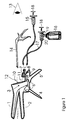
- Figure 1 illustrates a vaginal speculum arrangement composed by blades and handles, an extension rod mechanically coupled with the blades, and injection probe affixed onto the rod, a liquid marker container, and hydraulic means to enable injection of the marker.
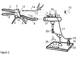
- Figure 2 illustrates a vaginal speculum arrangement composed of blades and handles, an extension rod mechanically coupled with the blades, and a mechanical support attached to a platform such as the ground or to the examination bed and connected detachably with the extension shaft. Onto the mechanical support and in the vicinity of its connection point with the extension shaft, the following components are mounted: an injection probe, a light source with a removable polarizer and removable rotating imaging polarizer, optical filter means and image magnifying optics.
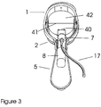
- Figure 3 illustrates a rear-view of a speculum in accordance with the teachings of the present invention.
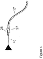
- Figure 4 illustrates a needle nozzle with a needle having an outside diameter sized to maximize the field-of-view through the rear aperture of a speculum in accordance with the teachings of the present invention. A coupling mechanism is used for connection of the needle nozzle with the tube providing a channel through which the marker flows.
- Figure 5 illustrates an apparatus for securing a speculum shaft onto an optical imaging system, or onto a base member.
- A Cusco-type speculum is illustrated in the figures for illustrative purposes and those skilled in the art will appreciate the present invention is not limited to such a speculum, but rather is applicable to any kind of speculum having a mechanical arrangement suitable for opening the vagina to enable the visualization of the tissues composing a woman's lower genital track.
- Figure 1 depicts a Cusco-type speculum having two blades (1, 2) connected to each other with the aid of a pivoting joint (3), located at the rear part of the blades. Each blade is jointed with the corresponding handle (4, 5) with the aid of a pin (6). The separation distance between the handles (4, 5) becomes maximum when the front parts of the blades (1, 2) are in contact. When the speculum is inserted into the vagina, the blades are in or near contact to each other, for the patient's comfort. After insertion, the handles (4, 5) are approached to each other, separating the blades (1, 2) and opening the vagina. The blade separation is mechanically locked at a desirable position, determined by the anatomy of the tissue. Then the examination follows involving the application of one or more diagnostic markers and the monitoring of the marker-induced alterations in the properties, e.g., the colour, of the tissue. As it has been stated above, the uniform application of a standardized quantity of the diagnostic marker, while simultaneously allowing for the tissue inspection is critical for examination and diagnostic evaluation.
- Uniform and simultaneous application of the marker over the entire area of the examined tissues can be achieved with the aid of a liquid injection mechanism, capable of dispensing the marker from a distance. In the case that the cervix of the uterus is examined, and because of its almost circular shape, a preferable injection pattern is conical with a maximum diameter equal with the diameter of the cervix, which is approximately 2.5-3 cm (1 inch).
- An injection probe (7) is preferably mounted properly onto a fixed position, so that its injection direction is not affected by the opening angle of the speculum blades (1, 2), which may vary due to the anatomy of the vagina. Such a fixed position cannot be achieved by affixing the injection probe on any of the blades, since by changing their angle the injection direction will change accordingly. Consequently, depending on the blade angle different parts of the tissue will be exposed to a different volume of the marker fluid.
- In the case of a Cusco-type speculum the blades open symmetrically around the speculum's pivoting joint (3), thus composing an eligible mount to affix the probe (7). Another solution, comprising another embodiment of the present invention is to affix the injection probe onto an extension shaft (8), which is mechanically coupled with the pins (6) connecting the handles with the blades. The front part of the shaft is jointed with the blade-handle joint of the first blade (4), while the pin of the blade-handle joint of the second blade (5) can slide within a groove (9), formed along the longitudinal axis of the extension shaft (8). This arrangement ensures that the relative position of the longitudinal axis of the probe (10) with the longitudinal symmetry axis of the blade system (11) remains the same for all possible blade angles. Therefore, by properly mounting the injection probe (7) onto the extension shaft (8), its longitudinal axis intersects the central area of the examined tissue in all possible relative positions of the blades (1, 2), thus ensuring uniform application of the marker in various anatomic conditions.
- In one embodiment of the present invention, the injection probe (7) is a nozzle remotely delivering a mist of liquid marker droplets of a desirable size onto the surface of the tissue. The cross section of the injection probe (7) is substantially smaller that the rear opening of the blade system (12) and preferably it has a needle nozzle-like shape for the purpose of not obscuring the visualization (13) of the tissue before, during and after injection and for allowing for the insertion of treatment tools (14). The liquid marker is transmitted to the injection probe (7) from a marker container (15, 16) either by permanently or detachably connecting these parts to each other, or through a tube (17) connecting these parts either permanently or detachably. The injection of the fluid is achieved with the aid of hydraulic pressure manually or otherwise applied.
- In one embodiment of the present invention, the container and the hydraulic means comprise a syringe with a container (15) and a piston (18). In another embodiment of the present invention, the container is bottle (16) and the hydraulic means is a tube with two one-way valves (19) and a piston (18). When the piston (18) is pulled out, the liquid fills-up the tube enclosing the piston with a desirable quantity of marker liquid and the valve of the bottle (19) closes. By pushing the piston in, the tube valve (20) opens, the bottle valve (19) closes and the liquid is injected from the injection probe (7). In one embodiment of the invention, more than one marker staining different features of diagnostic performance is performed with the arrangement described above either simultaneously or in time sequence.
- Clinical investigations conducted by the inventors of the present invention have shown that the optimum quantity of the marker is a volume of between about 2.5ml and 3.5 ml. This volume ensures a sufficient and uniform washing of the entire surface of the cervix to produce the diagnostic optical effect. At the same time, this volume is desirable, since it eliminates unwanted accumulation of marker in excess between the lower blade (20) and the lower part of the examined tissue, which may obscure the visualization of the tissue.
- The vaginal speculum arrangement of the present invention, as illustrated in Figure 1, may be manufactured either in part or in whole either from metallic or from synthetic (plastic, Plexiglas) material. The speculum arrangement of the present invention either in part or in whole, may be either re-usable or disposable. In one embodiment, the speculum arrangement comprising the blade and handle system, the extension shaft onto which the nozzle is affixed, the nozzle mechanically coupled with the syringe pre-filled with the marker, is disposable.
- Figure 2 depicts another embodiment of the vaginal speculum arrangement. The length of the extension shaft (8) is determined by the working distance of the optical imaging apparatus employed for the examination the lower part of woman's genital system, such as cameras, colposcopes etc. and combinations thereof. The extension shaft is detachably connected with these imaging apparatuses, with the aid of a locking mechanism (21). The locking mechanism (21) is affixed onto the imaging apparatus and at a proper location so that when the locking mechanism is coupled with the extension shaft, the longitudinal symmetry axis of the blade system (11) coincides substantially with the bisector of the viewing angle (13). In another embodiment of this invention, suitable for speculoscopy use, the locking mechanism (21) is mounted on a mechanical support, which in turn is either affixed onto the examination bed or includes a base (23) placed on the ground. The mechanical support may be an articulating arm (22) to facilitate manipulations for the connection of the speculum shaft (8) with the locking mechanism (21).
- Onto the mechanical support (22) and in the vicinity of its connection point with the extension shaft, the following components may be mounted: an injection probe (7), connected with a marker container (16, 15) either directly or though a tube (17) and hydraulic means for enabling injection, all having the specifications described above with respect to Figure 1, a light source (24) with a power supply (25) and at least one of the following optical elements (26) interposed in the illumination and imaging ray paths: magnifying and focusing optics, filters and polarizers. The optical elements (26) may be mounted in a removable manner from the path of the rays, by titling them left or right. The polarizers may be affixed on a mount allowing the rotation of their polarization axes.
- The cross section of the light source and illumination optics (24, 26) is substantially smaller than the rear optical aperture of the blade system (12) for the purpose of not obscuring the visualization of the tissue.
- The light source (24) may be a halogen lamp and/or a LED lamp or other suitable light source. When the polarization axis of the imaging polarizer becomes, after rotation, vertical with the polarization axis of the light source, then the surface reflection (glare) is eliminated, resulting in a substantial improvement of the perceived contrast. This facilitates the detection and monitoring of features of diagnostic importance. The perceived contrast is further enhanced with the aid of an optical filter and image magnifying means (26).
- Once the extension shaft (8) is connected with the mechanical support, the longitudinal axis of the injection probe (12) may have a fixed relative position with the longitudinal axis (11) of the blade system, ensuring that the former intersects the central area of the tissue and the uniform application of the marker onto the entire area of the examined tissue.
- The vaginal speculum arrangement of the current invention, illustrated in figure 2, may be manufactured either in part or in total either from metallic or from synthetic (plastic, Plexiglas) material. The speculum arrangement of the current invention may be in part either re-usable or disposable. In one preferable embodiment of the vaginal arrangement as depicted in Figure 2, the blade-handle system with the extension shaft is disposable and the mechanical mount with the components (in part or in whole) mounted on it, is re-usable.
- Figure 3 illustrates a rear-view of the joined speculum blades (1, 2), the extension shaft (8) and the nozzle (7). The dimensions of the cross section (40) of the nozzle is substantially smaller than the dimensions of the cross section (41) of a rear aperture (42) of the blade system, thus allowing for the visualization of the examined area before, during, and after the injection of the marker.
- Figure 4 illustrates a needle nozzle (27), with the needle (43) having an outside diameter sized to maximize the field-of-view through the rear aperture (42) of the blade system. A coupling mechanism (28) is used for the connection of the needle nozzle (27) with the tube (17) providing a channel for the marker from a container holding to marker to an input orifice of the coupling means (28).
- Figure 5 illustrates one embodiment of the shaft (8) in more detail. Those skilled in the art will appreciate the shaft (8) is not limited to the embodiment illustrated and other shaft configurations are possible. The shaft (8) illustrated in Figure 5 is well suited for use in securing the speculum shaft onto an optical imaging system (26), onto a base member (23), or both. In the illustrated embodiment, the distal end (29) of a speculum shaft (8) includes a conically tapered slot (30) in a bottom side. The conically tapered slot (30) acts as a guide for the proper alignment of the speculum with respect to the external optical system (26). A securing mechanism engages with the distal end (29) of the shaft (8) with an extension pin (31) that has a dowel pin (32) having a longitudinal axis perpendicular to the longitudinal axis of the extension pin (31). The position of the dowel pin (32) determines the displacement of the speculum from the external optical system. The distal end (29) of the shaft (8) engages with the extension pin (31) using a spring-loaded, cam action wedge (33). The distal end (29) of the shaft (8) also includes a receptacle slot (34) to mate with the cam action wedge (32).
- In operation, the shaft (8) is moved towards the optical system to urge the dowel pin (32) into contact with the conically tapered groove in the shaft (8) until the cam action wedge (33) mates with the receptacle slot (34) in the shaft (8).
- The shaft (8) is unlocked from the dowel pin (32) by pressing on a release button (35) which has the effect of engaging with the cam action wedge (32). In this state, the receptacle slot (34) is devoid of a locking member and the shaft (8) can be removed. The cam action wedge (32) and the release button (35) are returned to their normal states due to the action of the spring (36) housed in the engagement pin (31).
Claims (21)
- A vaginal speculum arrangement comprising,
a blade system for opening the vagina having a first blade (1) and a second blade (2) positionable relative to each other in a plurality of angles and a longitudinal symmetry axis (10) between a distal portion and a proximate portion of each of the first (1) and second blades (2), and
an injection mechanism for dispensing a diagnostic marker onto the surface of the examined tissue having an injection probe (7) having a longitudinal axis (11), a marker container (15,16) and a means for enabling injection of the marker (18),
wherein a relative position of the longitudinal axis of the injection probe (11) and the longitudinal symmetry axis of the blade system (10) remain substantially fixed for each of the plurality of angles between the first and second blades,
wherein the dimensions of the cross section of the injection probe (40) is substantially smaller than the dimensions of the cross section (41) of a rear aperture (42) of the blade system, and
wherein the injection probe (7) allows for a substantially homogeneous application of the diagnostic marker on a desired area in the examined vaginal or cervical tissue, irrespectively from the opening angle of the blades (1,2) and allows for observation of the desired area through the rear aperture of the blade system, before during and after the injection of the diagnostic marker. - The vaginal speculum arrangement of claim 1 wherein the vaginal speculum arrangement further comprises a mechanical support having a shaft (8) with a first shaft end mechanically coupled with the blade system and a second shaft end detachably coupled to the injection mechanism (7).
- The vaginal speculum arrangement of claim 1, wherein the vaginal speculum arrangement further comprises,a mechanical support having a shaft (8) with a first shaft end mechanically coupled with the blade system and a second shaft end detachably coupled to a base member (21) or to an imaging apparatus.
- The vaginal speculum arrangement of claim 1, further comprising a mechanical support having a shaft with a first shaft end mechanically coupled with the blade system and the injection probe (7) mounts to a portion of the shaft (8).
- The vaginal speculum arrangement of claims 2 or 4, wherein the first shaft end of said shaft (8) is jointed with a blade-handle joint of the first blade (6), and a pin of the blade-handle joint of the second blade (6) moves within a groove (9), formed along a longitudinal axis of said extension shaft (8).
- The vaginal speculum arrangement of claim 2, wherein the base member includes an articulated arm (22) with a first end portion affixed to a fixed position (23) and a second end portion affixed to a locking mechanism of the shaft (21).
- The vaginal speculum arrangement of claim 6, wherein said locking mechanism (21) includes one of a mechanical locking mechanism or a magnetic or an electromagnetic locking mechanism.
- The vaginal speculum arrangement of claim 7, wherein said injection probe (7) is affixed to said mechanical base in a vicinity of said locking mechanism.
- The vaginal speculum arrangement of claim 1, wherein said injection probe (7) comprises a nozzle.
- The vaginal speculum arrangement of claim 8 wherein said nozzle (7) comprises a needle nozzle (43).
- The vaginal speculum arrangement of claim 1, wherein the injection mechanism further comprises a hydraulic pump means (15, 16, 18,19,20) for pumping a predetermined volume of a marker into and through said injection probe (7).
- The vaginal speculum arrangement of claim 11, wherein said predetermined volume of the marker ranges between about 2.5 ml and about 3.5 ml.
- The vaginal speculum arrangement of claim 11, wherein said marker is between about 3% and about 5% acetic acid solution.
- The vaginal speculum arrangement of claim 1 further comprising a light source (24).
- The vaginal speculum arrangement of claim 6, further comprising a light source affixed to the base member in a vicinity of said shaft locking mechanism (21).
- The vaginal speculum arrangement of claim 1, further comprising an optical element (26).
- The vaginal speculum arrangement of claim 16, wherein the optical element (26) comprises one of a magnifying optical element, a focusable optical element, an optical filter or a pair of polarizers, one for polarizing the light emitted by the light source and one for polarizing the reflected by the tissue light, having their polarization axes perpendicular to each other.
- The vaginal speculum arrangement of claim 2 wherein said blade system, said shaft (8) and said injection probe (7) are formed from a metallic material.
- The vaginal speculum arrangement of claim 18 wherein said blade system, said shaft (8) and said injection probe (7) are re-usable.
- The vaginal speculum arrangement of claim 2, wherein said blade system, said shaft (8) and said injection means (7) each have a portion formed from a polymeric compound.
- The vaginal speculum arrangement of claim 20, wherein said blade system, said shaft (8) and said injection means (7) are disposable.
Priority Applications (12)
| Application Number | Priority Date | Filing Date | Title |
|---|---|---|---|
| PT05386023T PT1769731E (en) | 2005-09-29 | 2005-09-29 | Vaginal speculum arrangement |
| EP05386023A EP1769731B1 (en) | 2005-09-29 | 2005-09-29 | Vaginal speculum arrangement |
| DE602005013228T DE602005013228D1 (en) | 2005-09-29 | 2005-09-29 | vaginal speculum |
| AT05386023T ATE424755T1 (en) | 2005-09-29 | 2005-09-29 | VAGINAL SPECULUM |
| DK05386023T DK1769731T3 (en) | 2005-09-29 | 2005-09-29 | Vaginal speculum |
| ES05386023T ES2322481T3 (en) | 2005-09-29 | 2005-09-29 | VAGINAL SPECULUM DEVICE. |
| EP06794602.0A EP1928293B8 (en) | 2005-09-29 | 2006-09-29 | Vaginal speculum arrangement |
| US12/088,289 US20080306345A1 (en) | 2005-09-29 | 2006-09-29 | Vaginal Speculum Arrangement |
| PT06794602T PT1928293T (en) | 2005-09-29 | 2006-09-29 | Vaginal speculum arrangement |
| CN2006800359963A CN101277641B (en) | 2005-09-29 | 2006-09-29 | Vaginal speculum arrangement |
| JP2008532877A JP5380071B2 (en) | 2005-09-29 | 2006-09-29 | Colposcope structure |
| PCT/GB2006/003648 WO2007036744A2 (en) | 2005-09-29 | 2006-09-29 | Vaginal speculum arrangement |
Applications Claiming Priority (1)
| Application Number | Priority Date | Filing Date | Title |
|---|---|---|---|
| EP05386023A EP1769731B1 (en) | 2005-09-29 | 2005-09-29 | Vaginal speculum arrangement |
Publications (2)
| Publication Number | Publication Date |
|---|---|
| EP1769731A1 true EP1769731A1 (en) | 2007-04-04 |
| EP1769731B1 EP1769731B1 (en) | 2009-03-11 |
Family
ID=36170061
Family Applications (2)
| Application Number | Title | Priority Date | Filing Date |
|---|---|---|---|
| EP05386023A Active EP1769731B1 (en) | 2005-09-29 | 2005-09-29 | Vaginal speculum arrangement |
| EP06794602.0A Active EP1928293B8 (en) | 2005-09-29 | 2006-09-29 | Vaginal speculum arrangement |
Family Applications After (1)
| Application Number | Title | Priority Date | Filing Date |
|---|---|---|---|
| EP06794602.0A Active EP1928293B8 (en) | 2005-09-29 | 2006-09-29 | Vaginal speculum arrangement |
Country Status (10)
| Country | Link |
|---|---|
| US (1) | US20080306345A1 (en) |
| EP (2) | EP1769731B1 (en) |
| JP (1) | JP5380071B2 (en) |
| CN (1) | CN101277641B (en) |
| AT (1) | ATE424755T1 (en) |
| DE (1) | DE602005013228D1 (en) |
| DK (1) | DK1769731T3 (en) |
| ES (1) | ES2322481T3 (en) |
| PT (2) | PT1769731E (en) |
| WO (1) | WO2007036744A2 (en) |
Cited By (3)
| Publication number | Priority date | Publication date | Assignee | Title |
|---|---|---|---|---|
| WO2008125870A2 (en) * | 2007-04-11 | 2008-10-23 | Forth-Photonics Limited | A supporting structure and a workstation incorporating the supporting structure for improving, objectifying and documenting in vivo examinations of the uterus |
| GB2467573A (en) * | 2009-02-06 | 2010-08-11 | Parburch Medical Developments | Proctoscope with shielding window |
| CN114403945A (en) * | 2022-01-24 | 2022-04-29 | 罗春容 | Intelligent examination, diagnosis and treatment system for gynecological cervical diseases |
Families Citing this family (27)
| Publication number | Priority date | Publication date | Assignee | Title |
|---|---|---|---|---|
| AU2006232534B2 (en) | 2005-04-01 | 2011-10-06 | Welch Allyn, Inc. | Vaginal speculum |
| US20100305406A1 (en) * | 2009-05-26 | 2010-12-02 | Ori Braun | System, device and method for gynecological use |
| US9271640B2 (en) | 2009-11-10 | 2016-03-01 | Illumigyn Ltd. | Optical speculum |
| US8638995B2 (en) * | 2009-11-10 | 2014-01-28 | Illumigyn Ltd. | Optical speculum |
| US9877644B2 (en) | 2009-11-10 | 2018-01-30 | Illumigyn Ltd. | Optical speculum |
| IT1405000B1 (en) * | 2010-02-04 | 2013-12-16 | El En Spa | DEVICE FOR THE TREATMENT OF THE VAGINAL CHANNEL AND ITS APPARATUS |
| CN102525393A (en) * | 2012-01-18 | 2012-07-04 | 师伟 | Fixed-type self-lighting vaginal speculum for rats |
| CN103142207B (en) * | 2013-03-19 | 2015-06-17 | 亚新科技(珠海)发展有限公司 | Device for cervix surgery |
| US20160116380A1 (en) * | 2013-06-05 | 2016-04-28 | Snpshot Trustee Limited | Tissue sampler |
| EP3038543A4 (en) * | 2013-08-28 | 2017-03-22 | Alfred E. Mann Institute for Biomedical Engineering at the University of Southern California | Minimally obstructive retractor for vaginal repairs |
| WO2017117313A2 (en) | 2015-12-29 | 2017-07-06 | CEEK Enterprises | Sleeve for speculum and use thereof |
| EP3397133B1 (en) * | 2015-12-29 | 2020-04-22 | Ceek Women's Health, Inc. | Speculum with locking mechanism |
| CA3009515A1 (en) | 2015-12-29 | 2017-07-06 | CEEK Enterprises | Insertable sleeve for speculum and use thereof |
| CN105708410B (en) * | 2016-01-20 | 2018-05-22 | 广州普露医疗科技有限公司 | Vagina uterine neck examines and treat instrument |
| US11259785B2 (en) | 2016-09-16 | 2022-03-01 | Lida Aghdam | Vagina probe with brush |
| US20180177989A1 (en) * | 2016-12-28 | 2018-06-28 | Regen Medical Inc. | Vaginal rejuvenation methods and devices |
| CN106963379B (en) * | 2017-03-17 | 2020-08-21 | 中国人民解放军第三军医大学第一附属医院 | Terahertz imaging system |
| US10687699B2 (en) | 2017-03-17 | 2020-06-23 | CEEK Enterprises | Lighting module for a medical device and methods for using the same |
| USD963908S1 (en) | 2017-03-24 | 2022-09-13 | Ceek Women's Health, Inc. | Medical device lighting module |
| JP6926631B2 (en) * | 2017-04-25 | 2021-08-25 | ウシオ電機株式会社 | Fluorescence observation unit |
| CN107260115B (en) * | 2017-07-26 | 2023-06-23 | 浙江百安医疗科技有限公司 | Vaginal speculum with connecting ring |
| JP6516339B1 (en) * | 2018-03-12 | 2019-05-22 | 株式会社ナミキ・メディカルインストゥルメンツ | Medical device |
| CN108634922A (en) * | 2018-04-23 | 2018-10-12 | 山东丽鱼家具有限公司 | A kind of gynemetrics's inspection cleaning vaginal dilator |
| CN111643799B (en) * | 2020-06-16 | 2021-10-01 | 徐伟伟 | Drug delivery device for obstetrics and gynecology department |
| MX2020006458A (en) | 2020-06-18 | 2022-05-30 | Villa Juan Gerardo Barroso | Cannula stabilizer for embryonic transfer. |
| US20220000339A1 (en) * | 2020-07-06 | 2022-01-06 | Maine Medical Center | Diagnostic cervical scanning and treatment device |
| USD986415S1 (en) | 2020-09-11 | 2023-05-16 | Ceek Women's Health, Inc. | Speculum |
Citations (18)
| Publication number | Priority date | Publication date | Assignee | Title |
|---|---|---|---|---|
| GB191027965A (en) | 1910-02-17 | 1911-04-06 | Marcel Meyer | Improvements in Therapeutic Injecting Apparatus. |
| GB214913A (en) | 1923-09-29 | 1924-05-01 | Howard Glenn Carter | Improvements in vaginal syringes |
| US3762400A (en) | 1971-10-26 | 1973-10-02 | Donald B Mc | Medical examining instrument |
| US3789829A (en) * | 1971-06-01 | 1974-02-05 | H Hasson | Vaginal radium applicator |
| US3851642A (en) | 1971-10-26 | 1974-12-03 | Medical Testing Syst Inc | Medical examining instrument |
| GB1408382A (en) | 1972-08-14 | 1975-10-01 | Mcdonald B | Specula |
| FR2328440A1 (en) * | 1975-10-21 | 1977-05-20 | Ortiz Castaneda Jimeno | COLPOMICROSCOPE |
| US4046140A (en) | 1972-06-02 | 1977-09-06 | Born Grant R | Cervix photographic method |
| US4210133A (en) | 1975-10-21 | 1980-07-01 | Consejo Nacional De Ciencia Y Tecnologia | Vaginal microscope |
| WO1990007299A1 (en) | 1988-12-28 | 1990-07-12 | Adair Edwin Lloyd | Method and apparatus for cervical videoscopy |
| WO1993019678A2 (en) * | 1991-12-03 | 1993-10-14 | Vesitec Medical, Inc. | Surgical treatment of stress urinary incontinence |
| US5458595A (en) * | 1993-12-16 | 1995-10-17 | The Regents Of The University Of California | Vaginal speculum for photodynamic therapy and method of using the same |
| WO1997028753A1 (en) | 1996-02-07 | 1997-08-14 | Pinotage, Llc | Video gynecological examination apparatus |
| US20020197728A1 (en) * | 1999-12-15 | 2002-12-26 | Howard Kaufman | Methods of monitoring effects of chemical agents on a sample |
| US20030225313A1 (en) * | 2002-06-04 | 2003-12-04 | German Borodulin | Vaginal speculum with insertable one-lens colposcope |
| US20040122327A1 (en) | 2000-12-15 | 2004-06-24 | Amir Belson | Intrauterine imaging system |
| US20050090751A1 (en) * | 2000-03-28 | 2005-04-28 | Foundation For Research And Technology | Method and system for characterization and mapping of tissue lesions |
| WO2005055819A1 (en) * | 2003-12-15 | 2005-06-23 | Uset Medical Ltd. | Vaginal speculum assembly |
Family Cites Families (8)
| Publication number | Priority date | Publication date | Assignee | Title |
|---|---|---|---|---|
| US3815585A (en) * | 1971-01-14 | 1974-06-11 | Bio Analytical Labor Inc | Disposable vaginal speculum |
| US5143054A (en) * | 1988-12-28 | 1992-09-01 | Adair Edwin Lloyd | Cervical videoscope with detachable camera unit |
| US5072720A (en) * | 1990-01-08 | 1991-12-17 | Francis Walter C | Vaginal speculum |
| JP2768532B2 (en) * | 1990-02-02 | 1998-06-25 | エル アデア エドウィン | Cervical observation device |
| WO1993023552A1 (en) * | 1992-05-21 | 1993-11-25 | Government Of The United States As Represented By Secretary Department Of Health And Human Services | Targeting gene expression to living tissue using jet injection |
| US5951461A (en) * | 1996-12-20 | 1999-09-14 | Nyo; Tin | Image-guided laryngoscope for tracheal intubation |
| US6432049B1 (en) * | 2000-08-29 | 2002-08-13 | Linda Kay Banta | Adjustable vaginal speculum light |
| US8142352B2 (en) * | 2006-04-03 | 2012-03-27 | Welch Allyn, Inc. | Vaginal speculum assembly having portable illuminator |
-
2005
- 2005-09-29 DK DK05386023T patent/DK1769731T3/en active
- 2005-09-29 EP EP05386023A patent/EP1769731B1/en active Active
- 2005-09-29 AT AT05386023T patent/ATE424755T1/en active
- 2005-09-29 DE DE602005013228T patent/DE602005013228D1/en active Active
- 2005-09-29 PT PT05386023T patent/PT1769731E/en unknown
- 2005-09-29 ES ES05386023T patent/ES2322481T3/en active Active
-
2006
- 2006-09-29 WO PCT/GB2006/003648 patent/WO2007036744A2/en active Application Filing
- 2006-09-29 CN CN2006800359963A patent/CN101277641B/en active Active
- 2006-09-29 PT PT06794602T patent/PT1928293T/en unknown
- 2006-09-29 EP EP06794602.0A patent/EP1928293B8/en active Active
- 2006-09-29 JP JP2008532877A patent/JP5380071B2/en active Active
- 2006-09-29 US US12/088,289 patent/US20080306345A1/en not_active Abandoned
Patent Citations (19)
| Publication number | Priority date | Publication date | Assignee | Title |
|---|---|---|---|---|
| GB191027965A (en) | 1910-02-17 | 1911-04-06 | Marcel Meyer | Improvements in Therapeutic Injecting Apparatus. |
| GB214913A (en) | 1923-09-29 | 1924-05-01 | Howard Glenn Carter | Improvements in vaginal syringes |
| US3789829A (en) * | 1971-06-01 | 1974-02-05 | H Hasson | Vaginal radium applicator |
| US3762400A (en) | 1971-10-26 | 1973-10-02 | Donald B Mc | Medical examining instrument |
| US3851642A (en) | 1971-10-26 | 1974-12-03 | Medical Testing Syst Inc | Medical examining instrument |
| US4046140A (en) | 1972-06-02 | 1977-09-06 | Born Grant R | Cervix photographic method |
| GB1408382A (en) | 1972-08-14 | 1975-10-01 | Mcdonald B | Specula |
| US4210133A (en) | 1975-10-21 | 1980-07-01 | Consejo Nacional De Ciencia Y Tecnologia | Vaginal microscope |
| FR2328440A1 (en) * | 1975-10-21 | 1977-05-20 | Ortiz Castaneda Jimeno | COLPOMICROSCOPE |
| WO1990007299A1 (en) | 1988-12-28 | 1990-07-12 | Adair Edwin Lloyd | Method and apparatus for cervical videoscopy |
| WO1993019678A2 (en) * | 1991-12-03 | 1993-10-14 | Vesitec Medical, Inc. | Surgical treatment of stress urinary incontinence |
| US5458595A (en) * | 1993-12-16 | 1995-10-17 | The Regents Of The University Of California | Vaginal speculum for photodynamic therapy and method of using the same |
| WO1997028753A1 (en) | 1996-02-07 | 1997-08-14 | Pinotage, Llc | Video gynecological examination apparatus |
| US20020197728A1 (en) * | 1999-12-15 | 2002-12-26 | Howard Kaufman | Methods of monitoring effects of chemical agents on a sample |
| US20030207250A1 (en) * | 1999-12-15 | 2003-11-06 | Medispectra, Inc. | Methods of diagnosing disease |
| US20050090751A1 (en) * | 2000-03-28 | 2005-04-28 | Foundation For Research And Technology | Method and system for characterization and mapping of tissue lesions |
| US20040122327A1 (en) | 2000-12-15 | 2004-06-24 | Amir Belson | Intrauterine imaging system |
| US20030225313A1 (en) * | 2002-06-04 | 2003-12-04 | German Borodulin | Vaginal speculum with insertable one-lens colposcope |
| WO2005055819A1 (en) * | 2003-12-15 | 2005-06-23 | Uset Medical Ltd. | Vaginal speculum assembly |
Cited By (5)
| Publication number | Priority date | Publication date | Assignee | Title |
|---|---|---|---|---|
| WO2008125870A2 (en) * | 2007-04-11 | 2008-10-23 | Forth-Photonics Limited | A supporting structure and a workstation incorporating the supporting structure for improving, objectifying and documenting in vivo examinations of the uterus |
| WO2008125870A3 (en) * | 2007-04-11 | 2009-07-23 | Forth Photonics Ltd | A supporting structure and a workstation incorporating the supporting structure for improving, objectifying and documenting in vivo examinations of the uterus |
| GB2467573A (en) * | 2009-02-06 | 2010-08-11 | Parburch Medical Developments | Proctoscope with shielding window |
| GB2467573B (en) * | 2009-02-06 | 2011-01-12 | Parburch Medical Developments Ltd | Proctoscope |
| CN114403945A (en) * | 2022-01-24 | 2022-04-29 | 罗春容 | Intelligent examination, diagnosis and treatment system for gynecological cervical diseases |
Also Published As
| Publication number | Publication date |
|---|---|
| DK1769731T3 (en) | 2009-07-06 |
| PT1769731E (en) | 2009-04-03 |
| JP2009509606A (en) | 2009-03-12 |
| EP1769731B1 (en) | 2009-03-11 |
| US20080306345A1 (en) | 2008-12-11 |
| DE602005013228D1 (en) | 2009-04-23 |
| EP1928293A2 (en) | 2008-06-11 |
| CN101277641B (en) | 2010-06-16 |
| EP1928293B8 (en) | 2018-10-24 |
| CN101277641A (en) | 2008-10-01 |
| ES2322481T3 (en) | 2009-06-22 |
| WO2007036744A2 (en) | 2007-04-05 |
| EP1928293B1 (en) | 2018-09-05 |
| WO2007036744A3 (en) | 2007-06-14 |
| ATE424755T1 (en) | 2009-03-15 |
| JP5380071B2 (en) | 2014-01-08 |
| PT1928293T (en) | 2018-12-03 |
Similar Documents
| Publication | Publication Date | Title |
|---|---|---|
| EP1769731B1 (en) | Vaginal speculum arrangement | |
| US7749162B2 (en) | Vaginal speculum arrangement | |
| US6712761B2 (en) | Combination of a vaginal speculum with a single-lens colposcope | |
| US9877644B2 (en) | Optical speculum | |
| US7515952B2 (en) | System for characterization and mapping of tissue lesions | |
| US20070213590A1 (en) | Apparatus and methods for examining, visualizing, diagnosing, manipulating, treating and recording of abnormalities within interior regions of body cavities | |
| KR102567918B1 (en) | Optical speculum | |
| JP2003534056A (en) | Guide wire with observation function | |
| WO2015007233A1 (en) | Ureterorenoscope with bendable head end | |
| JP6830356B2 (en) | Surveillance system for continuous detection of the uterus | |
| US20230022536A1 (en) | Brush biopsy device, kit and method | |
| NL1027678C2 (en) | Device and method for examining a body cavity. | |
| CN106419822B (en) | A kind of integral joint lens device | |
| CN217338538U (en) | Bimodal optical coherence tomography endoscopic probe | |
| CN111166276A (en) | Near-infrared fluorescence imaging detection system for ovary through abdominal cavity-laparoscope | |
| WO2009059355A1 (en) | Examination device | |
| WO2023085917A1 (en) | Auxiliary apparatus used in cervical cancer diagnosis | |
| BR102015026020A2 (en) | MICROENDOSCOPE OF REFLECTABILITY AND PORTABLE FLUORESCENCE, COUPLED TO SMARTPHONES AND SIMILARS, AND ITS USES | |
| WO2007131263A1 (en) | Examination device | |
| AU2001244423B2 (en) | Method and system for characterization and mapping of tissue lesions | |
| Wu et al. | Fallopian Tube Imaging Using An Articulating Confocal Microlaparoscope | |
| Enomoto et al. | An endoscopic observation of intraductal papillary lesion | |
| Wu et al. | Confocal microlaparoscope for imaging the fallopian tube | |
| AU2001244423A1 (en) | Method and system for characterization and mapping of tissue lesions |
Legal Events
| Date | Code | Title | Description |
|---|---|---|---|
| PUAI | Public reference made under article 153(3) epc to a published international application that has entered the european phase |
Free format text: ORIGINAL CODE: 0009012 |
|
| 17P | Request for examination filed |
Effective date: 20070208 |
|
| AK | Designated contracting states |
Kind code of ref document: A1 Designated state(s): AT BE BG CH CY CZ DE DK EE ES FI FR GB GR HU IE IS IT LI LT LU LV MC NL PL PT RO SE SI SK TR |
|
| AX | Request for extension of the european patent |
Extension state: AL BA HR MK YU |
|
| AKX | Designation fees paid |
Designated state(s): AT BE BG CH CY CZ DE DK EE ES FI FR GB GR HU IE IS IT LI LT LU LV MC NL PL PT RO SE SI SK TR |
|
| AXX | Extension fees paid |
Extension state: BA Payment date: 20070517 Extension state: HR Payment date: 20070517 Extension state: YU Payment date: 20070517 Extension state: AL Payment date: 20070517 Extension state: MK Payment date: 20070517 |
|
| GRAP | Despatch of communication of intention to grant a patent |
Free format text: ORIGINAL CODE: EPIDOSNIGR1 |
|
| GRAS | Grant fee paid |
Free format text: ORIGINAL CODE: EPIDOSNIGR3 |
|
| GRAA | (expected) grant |
Free format text: ORIGINAL CODE: 0009210 |
|
| AK | Designated contracting states |
Kind code of ref document: B1 Designated state(s): AT BE BG CH CY CZ DE DK EE ES FI FR GB GR HU IE IS IT LI LT LU LV MC NL PL PT RO SE SI SK TR |
|
| AX | Request for extension of the european patent |
Extension state: AL BA HR MK YU |
|
| REG | Reference to a national code |
Ref country code: GB Ref legal event code: FG4D |
|
| REG | Reference to a national code |
Ref country code: CH Ref legal event code: EP |
|
| REG | Reference to a national code |
Ref country code: PT Ref legal event code: SC4A Free format text: AVAILABILITY OF NATIONAL TRANSLATION Effective date: 20090326 |
|
| REG | Reference to a national code |
Ref country code: CH Ref legal event code: NV Representative=s name: KIRKER & CIE S.A. Ref country code: IE Ref legal event code: FG4D |
|
| REF | Corresponds to: |
Ref document number: 602005013228 Country of ref document: DE Date of ref document: 20090423 Kind code of ref document: P |
|
| REG | Reference to a national code |
Ref country code: SE Ref legal event code: TRGR |
|
| REG | Reference to a national code |
Ref country code: GR Ref legal event code: EP Ref document number: 20090401204 Country of ref document: GR |
|
| REG | Reference to a national code |
Ref country code: ES Ref legal event code: FG2A Ref document number: 2322481 Country of ref document: ES Kind code of ref document: T3 |
|
| REG | Reference to a national code |
Ref country code: DK Ref legal event code: T3 |
|
| PG25 | Lapsed in a contracting state [announced via postgrant information from national office to epo] |
Ref country code: SI Free format text: LAPSE BECAUSE OF FAILURE TO SUBMIT A TRANSLATION OF THE DESCRIPTION OR TO PAY THE FEE WITHIN THE PRESCRIBED TIME-LIMIT Effective date: 20090311 Ref country code: LT Free format text: LAPSE BECAUSE OF FAILURE TO SUBMIT A TRANSLATION OF THE DESCRIPTION OR TO PAY THE FEE WITHIN THE PRESCRIBED TIME-LIMIT Effective date: 20090311 |
|
| PG25 | Lapsed in a contracting state [announced via postgrant information from national office to epo] |
Ref country code: PL Free format text: LAPSE BECAUSE OF FAILURE TO SUBMIT A TRANSLATION OF THE DESCRIPTION OR TO PAY THE FEE WITHIN THE PRESCRIBED TIME-LIMIT Effective date: 20090311 Ref country code: LV Free format text: LAPSE BECAUSE OF FAILURE TO SUBMIT A TRANSLATION OF THE DESCRIPTION OR TO PAY THE FEE WITHIN THE PRESCRIBED TIME-LIMIT Effective date: 20090311 |
|
| PG25 | Lapsed in a contracting state [announced via postgrant information from national office to epo] |
Ref country code: EE Free format text: LAPSE BECAUSE OF FAILURE TO SUBMIT A TRANSLATION OF THE DESCRIPTION OR TO PAY THE FEE WITHIN THE PRESCRIBED TIME-LIMIT Effective date: 20090311 Ref country code: CZ Free format text: LAPSE BECAUSE OF FAILURE TO SUBMIT A TRANSLATION OF THE DESCRIPTION OR TO PAY THE FEE WITHIN THE PRESCRIBED TIME-LIMIT Effective date: 20090311 |
|
| PGFP | Annual fee paid to national office [announced via postgrant information from national office to epo] |
Ref country code: DK Payment date: 20090914 Year of fee payment: 5 Ref country code: MC Payment date: 20090908 Year of fee payment: 5 |
|
| PG25 | Lapsed in a contracting state [announced via postgrant information from national office to epo] |
Ref country code: SK Free format text: LAPSE BECAUSE OF FAILURE TO SUBMIT A TRANSLATION OF THE DESCRIPTION OR TO PAY THE FEE WITHIN THE PRESCRIBED TIME-LIMIT Effective date: 20090311 Ref country code: RO Free format text: LAPSE BECAUSE OF FAILURE TO SUBMIT A TRANSLATION OF THE DESCRIPTION OR TO PAY THE FEE WITHIN THE PRESCRIBED TIME-LIMIT Effective date: 20090311 Ref country code: IS Free format text: LAPSE BECAUSE OF FAILURE TO SUBMIT A TRANSLATION OF THE DESCRIPTION OR TO PAY THE FEE WITHIN THE PRESCRIBED TIME-LIMIT Effective date: 20090711 |
|
| PGFP | Annual fee paid to national office [announced via postgrant information from national office to epo] |
Ref country code: FI Payment date: 20090918 Year of fee payment: 5 Ref country code: LU Payment date: 20090910 Year of fee payment: 5 |
|
| PGFP | Annual fee paid to national office [announced via postgrant information from national office to epo] |
Ref country code: CY Payment date: 20090907 Year of fee payment: 5 |
|
| PLBE | No opposition filed within time limit |
Free format text: ORIGINAL CODE: 0009261 |
|
| STAA | Information on the status of an ep patent application or granted ep patent |
Free format text: STATUS: NO OPPOSITION FILED WITHIN TIME LIMIT |
|
| PG25 | Lapsed in a contracting state [announced via postgrant information from national office to epo] |
Ref country code: BG Free format text: LAPSE BECAUSE OF FAILURE TO SUBMIT A TRANSLATION OF THE DESCRIPTION OR TO PAY THE FEE WITHIN THE PRESCRIBED TIME-LIMIT Effective date: 20090611 |
|
| 26N | No opposition filed |
Effective date: 20091214 |
|
| PG25 | Lapsed in a contracting state [announced via postgrant information from national office to epo] |
Ref country code: MC Free format text: LAPSE BECAUSE OF NON-PAYMENT OF DUE FEES Effective date: 20100930 |
|
| REG | Reference to a national code |
Ref country code: DK Ref legal event code: EBP |
|
| PG25 | Lapsed in a contracting state [announced via postgrant information from national office to epo] |
Ref country code: FI Free format text: LAPSE BECAUSE OF NON-PAYMENT OF DUE FEES Effective date: 20100929 Ref country code: CY Free format text: LAPSE BECAUSE OF NON-PAYMENT OF DUE FEES Effective date: 20100929 |
|
| PG25 | Lapsed in a contracting state [announced via postgrant information from national office to epo] |
Ref country code: HU Free format text: LAPSE BECAUSE OF FAILURE TO SUBMIT A TRANSLATION OF THE DESCRIPTION OR TO PAY THE FEE WITHIN THE PRESCRIBED TIME-LIMIT Effective date: 20090912 |
|
| PG25 | Lapsed in a contracting state [announced via postgrant information from national office to epo] |
Ref country code: DK Free format text: LAPSE BECAUSE OF NON-PAYMENT OF DUE FEES Effective date: 20100930 |
|
| PG25 | Lapsed in a contracting state [announced via postgrant information from national office to epo] |
Ref country code: LU Free format text: LAPSE BECAUSE OF NON-PAYMENT OF DUE FEES Effective date: 20100929 |
|
| REG | Reference to a national code |
Ref country code: FR Ref legal event code: PLFP Year of fee payment: 12 |
|
| REG | Reference to a national code |
Ref country code: DE Ref legal event code: R082 Ref document number: 602005013228 Country of ref document: DE Representative=s name: WEICKMANN & WEICKMANN PATENTANWAELTE - RECHTSA, DE Ref country code: DE Ref legal event code: R081 Ref document number: 602005013228 Country of ref document: DE Owner name: DYSIS MEDICAL LTD., GB Free format text: FORMER OWNER: FORTH-PHOTONICS LTD., LONDON, GB Ref country code: DE Ref legal event code: R082 Ref document number: 602005013228 Country of ref document: DE Representative=s name: WEICKMANN & WEICKMANN PATENT- UND RECHTSANWAEL, DE |
|
| REG | Reference to a national code |
Ref country code: NL Ref legal event code: HC Owner name: DYSIS MEDICAL LIMITED; GB Free format text: DETAILS ASSIGNMENT: CHANGE OF OWNER(S), CHANGE OF OWNER(S) NAME; FORMER OWNER NAME: FORTH-PHOTONICS LTD Effective date: 20170220 |
|
| REG | Reference to a national code |
Ref country code: GB Ref legal event code: 732E Free format text: REGISTERED BETWEEN 20170309 AND 20170315 |
|
| REG | Reference to a national code |
Ref country code: CH Ref legal event code: PFA Owner name: DYSIS MEDICAL LIMITED, GB Free format text: FORMER OWNER: FORTH-PHOTONICS LTD, GB |
|
| REG | Reference to a national code |
Ref country code: AT Ref legal event code: HC Ref document number: 424755 Country of ref document: AT Kind code of ref document: T Owner name: DYSIS MEDICAL LIMITED, GB Effective date: 20170530 |
|
| REG | Reference to a national code |
Ref country code: FR Ref legal event code: CA Effective date: 20170622 Ref country code: FR Ref legal event code: CD Owner name: DYSIS MEDICAL LIMITED, GB Effective date: 20170622 |
|
| REG | Reference to a national code |
Ref country code: FR Ref legal event code: PLFP Year of fee payment: 13 |
|
| REG | Reference to a national code |
Ref country code: ES Ref legal event code: PC2A Owner name: DYSIS MEDICAL LIMITED Effective date: 20170929 |
|
| REG | Reference to a national code |
Ref country code: FR Ref legal event code: PLFP Year of fee payment: 14 |
|
| PGFP | Annual fee paid to national office [announced via postgrant information from national office to epo] |
Ref country code: TR Payment date: 20230921 Year of fee payment: 19 Ref country code: NL Payment date: 20230921 Year of fee payment: 19 Ref country code: IE Payment date: 20230922 Year of fee payment: 19 Ref country code: GB Payment date: 20230919 Year of fee payment: 19 Ref country code: AT Payment date: 20230921 Year of fee payment: 19 |
|
| PGFP | Annual fee paid to national office [announced via postgrant information from national office to epo] |
Ref country code: SE Payment date: 20230929 Year of fee payment: 19 Ref country code: PT Payment date: 20230926 Year of fee payment: 19 Ref country code: GR Payment date: 20230925 Year of fee payment: 19 Ref country code: FR Payment date: 20230922 Year of fee payment: 19 Ref country code: DE Payment date: 20230921 Year of fee payment: 19 Ref country code: BE Payment date: 20230921 Year of fee payment: 19 |
|
| PGFP | Annual fee paid to national office [announced via postgrant information from national office to epo] |
Ref country code: ES Payment date: 20231005 Year of fee payment: 19 |
|
| PGFP | Annual fee paid to national office [announced via postgrant information from national office to epo] |
Ref country code: IT Payment date: 20230926 Year of fee payment: 19 Ref country code: CH Payment date: 20231002 Year of fee payment: 19 |