EP1767967A2 - Led lamp with direct optical coupling to an optical light guide having purality of light pipes in axial arrangement - Google Patents
Led lamp with direct optical coupling to an optical light guide having purality of light pipes in axial arrangement Download PDFInfo
- Publication number
- EP1767967A2 EP1767967A2 EP06017804A EP06017804A EP1767967A2 EP 1767967 A2 EP1767967 A2 EP 1767967A2 EP 06017804 A EP06017804 A EP 06017804A EP 06017804 A EP06017804 A EP 06017804A EP 1767967 A2 EP1767967 A2 EP 1767967A2
- Authority
- EP
- European Patent Office
- Prior art keywords
- light
- light guide
- optical
- pipes
- led
- Prior art date
- Legal status (The legal status is an assumption and is not a legal conclusion. Google has not performed a legal analysis and makes no representation as to the accuracy of the status listed.)
- Granted
Links
Images


Classifications
-
- F—MECHANICAL ENGINEERING; LIGHTING; HEATING; WEAPONS; BLASTING
- F21—LIGHTING
- F21V—FUNCTIONAL FEATURES OR DETAILS OF LIGHTING DEVICES OR SYSTEMS THEREOF; STRUCTURAL COMBINATIONS OF LIGHTING DEVICES WITH OTHER ARTICLES, NOT OTHERWISE PROVIDED FOR
- F21V29/00—Protecting lighting devices from thermal damage; Cooling or heating arrangements specially adapted for lighting devices or systems
- F21V29/50—Cooling arrangements
- F21V29/70—Cooling arrangements characterised by passive heat-dissipating elements, e.g. heat-sinks
- F21V29/74—Cooling arrangements characterised by passive heat-dissipating elements, e.g. heat-sinks with fins or blades
-
- B—PERFORMING OPERATIONS; TRANSPORTING
- B60—VEHICLES IN GENERAL
- B60Q—ARRANGEMENT OF SIGNALLING OR LIGHTING DEVICES, THE MOUNTING OR SUPPORTING THEREOF OR CIRCUITS THEREFOR, FOR VEHICLES IN GENERAL
- B60Q1/00—Arrangement of optical signalling or lighting devices, the mounting or supporting thereof or circuits therefor
- B60Q1/26—Arrangement of optical signalling or lighting devices, the mounting or supporting thereof or circuits therefor the devices being primarily intended to indicate the vehicle, or parts thereof, or to give signals, to other traffic
- B60Q1/2696—Mounting of devices using LEDs
-
- F—MECHANICAL ENGINEERING; LIGHTING; HEATING; WEAPONS; BLASTING
- F21—LIGHTING
- F21K—NON-ELECTRIC LIGHT SOURCES USING LUMINESCENCE; LIGHT SOURCES USING ELECTROCHEMILUMINESCENCE; LIGHT SOURCES USING CHARGES OF COMBUSTIBLE MATERIAL; LIGHT SOURCES USING SEMICONDUCTOR DEVICES AS LIGHT-GENERATING ELEMENTS; LIGHT SOURCES NOT OTHERWISE PROVIDED FOR
- F21K9/00—Light sources using semiconductor devices as light-generating elements, e.g. using light-emitting diodes [LED] or lasers
-
- F—MECHANICAL ENGINEERING; LIGHTING; HEATING; WEAPONS; BLASTING
- F21—LIGHTING
- F21S—NON-PORTABLE LIGHTING DEVICES; SYSTEMS THEREOF; VEHICLE LIGHTING DEVICES SPECIALLY ADAPTED FOR VEHICLE EXTERIORS
- F21S43/00—Signalling devices specially adapted for vehicle exteriors, e.g. brake lamps, direction indicator lights or reversing lights
- F21S43/10—Signalling devices specially adapted for vehicle exteriors, e.g. brake lamps, direction indicator lights or reversing lights characterised by the light source
- F21S43/13—Signalling devices specially adapted for vehicle exteriors, e.g. brake lamps, direction indicator lights or reversing lights characterised by the light source characterised by the type of light source
- F21S43/14—Light emitting diodes [LED]
-
- F—MECHANICAL ENGINEERING; LIGHTING; HEATING; WEAPONS; BLASTING
- F21—LIGHTING
- F21S—NON-PORTABLE LIGHTING DEVICES; SYSTEMS THEREOF; VEHICLE LIGHTING DEVICES SPECIALLY ADAPTED FOR VEHICLE EXTERIORS
- F21S43/00—Signalling devices specially adapted for vehicle exteriors, e.g. brake lamps, direction indicator lights or reversing lights
- F21S43/20—Signalling devices specially adapted for vehicle exteriors, e.g. brake lamps, direction indicator lights or reversing lights characterised by refractors, transparent cover plates, light guides or filters
- F21S43/235—Light guides
- F21S43/236—Light guides characterised by the shape of the light guide
- F21S43/237—Light guides characterised by the shape of the light guide rod-shaped
-
- F—MECHANICAL ENGINEERING; LIGHTING; HEATING; WEAPONS; BLASTING
- F21—LIGHTING
- F21S—NON-PORTABLE LIGHTING DEVICES; SYSTEMS THEREOF; VEHICLE LIGHTING DEVICES SPECIALLY ADAPTED FOR VEHICLE EXTERIORS
- F21S43/00—Signalling devices specially adapted for vehicle exteriors, e.g. brake lamps, direction indicator lights or reversing lights
- F21S43/20—Signalling devices specially adapted for vehicle exteriors, e.g. brake lamps, direction indicator lights or reversing lights characterised by refractors, transparent cover plates, light guides or filters
- F21S43/235—Light guides
- F21S43/236—Light guides characterised by the shape of the light guide
- F21S43/241—Light guides characterised by the shape of the light guide of complex shape
-
- F—MECHANICAL ENGINEERING; LIGHTING; HEATING; WEAPONS; BLASTING
- F21—LIGHTING
- F21S—NON-PORTABLE LIGHTING DEVICES; SYSTEMS THEREOF; VEHICLE LIGHTING DEVICES SPECIALLY ADAPTED FOR VEHICLE EXTERIORS
- F21S43/00—Signalling devices specially adapted for vehicle exteriors, e.g. brake lamps, direction indicator lights or reversing lights
- F21S43/20—Signalling devices specially adapted for vehicle exteriors, e.g. brake lamps, direction indicator lights or reversing lights characterised by refractors, transparent cover plates, light guides or filters
- F21S43/235—Light guides
- F21S43/242—Light guides characterised by the emission area
- F21S43/243—Light guides characterised by the emission area emitting light from one or more of its extremities
-
- F—MECHANICAL ENGINEERING; LIGHTING; HEATING; WEAPONS; BLASTING
- F21—LIGHTING
- F21S—NON-PORTABLE LIGHTING DEVICES; SYSTEMS THEREOF; VEHICLE LIGHTING DEVICES SPECIALLY ADAPTED FOR VEHICLE EXTERIORS
- F21S43/00—Signalling devices specially adapted for vehicle exteriors, e.g. brake lamps, direction indicator lights or reversing lights
- F21S43/20—Signalling devices specially adapted for vehicle exteriors, e.g. brake lamps, direction indicator lights or reversing lights characterised by refractors, transparent cover plates, light guides or filters
- F21S43/235—Light guides
- F21S43/242—Light guides characterised by the emission area
- F21S43/245—Light guides characterised by the emission area emitting light from one or more of its major surfaces
-
- F—MECHANICAL ENGINEERING; LIGHTING; HEATING; WEAPONS; BLASTING
- F21—LIGHTING
- F21S—NON-PORTABLE LIGHTING DEVICES; SYSTEMS THEREOF; VEHICLE LIGHTING DEVICES SPECIALLY ADAPTED FOR VEHICLE EXTERIORS
- F21S43/00—Signalling devices specially adapted for vehicle exteriors, e.g. brake lamps, direction indicator lights or reversing lights
- F21S43/20—Signalling devices specially adapted for vehicle exteriors, e.g. brake lamps, direction indicator lights or reversing lights characterised by refractors, transparent cover plates, light guides or filters
- F21S43/235—Light guides
- F21S43/247—Light guides with a single light source being coupled into the light guide
-
- F—MECHANICAL ENGINEERING; LIGHTING; HEATING; WEAPONS; BLASTING
- F21—LIGHTING
- F21V—FUNCTIONAL FEATURES OR DETAILS OF LIGHTING DEVICES OR SYSTEMS THEREOF; STRUCTURAL COMBINATIONS OF LIGHTING DEVICES WITH OTHER ARTICLES, NOT OTHERWISE PROVIDED FOR
- F21V29/00—Protecting lighting devices from thermal damage; Cooling or heating arrangements specially adapted for lighting devices or systems
- F21V29/50—Cooling arrangements
- F21V29/70—Cooling arrangements characterised by passive heat-dissipating elements, e.g. heat-sinks
- F21V29/74—Cooling arrangements characterised by passive heat-dissipating elements, e.g. heat-sinks with fins or blades
- F21V29/77—Cooling arrangements characterised by passive heat-dissipating elements, e.g. heat-sinks with fins or blades with essentially identical diverging planar fins or blades, e.g. with fan-like or star-like cross-section
- F21V29/773—Cooling arrangements characterised by passive heat-dissipating elements, e.g. heat-sinks with fins or blades with essentially identical diverging planar fins or blades, e.g. with fan-like or star-like cross-section the planes containing the fins or blades having the direction of the light emitting axis
-
- G—PHYSICS
- G02—OPTICS
- G02B—OPTICAL ELEMENTS, SYSTEMS OR APPARATUS
- G02B6/00—Light guides; Structural details of arrangements comprising light guides and other optical elements, e.g. couplings
- G02B6/0001—Light guides; Structural details of arrangements comprising light guides and other optical elements, e.g. couplings specially adapted for lighting devices or systems
-
- G—PHYSICS
- G02—OPTICS
- G02B—OPTICAL ELEMENTS, SYSTEMS OR APPARATUS
- G02B6/00—Light guides; Structural details of arrangements comprising light guides and other optical elements, e.g. couplings
- G02B6/24—Coupling light guides
- G02B6/42—Coupling light guides with opto-electronic elements
- G02B6/4201—Packages, e.g. shape, construction, internal or external details
- G02B6/4251—Sealed packages
-
- G—PHYSICS
- G02—OPTICS
- G02B—OPTICAL ELEMENTS, SYSTEMS OR APPARATUS
- G02B6/00—Light guides; Structural details of arrangements comprising light guides and other optical elements, e.g. couplings
- G02B6/24—Coupling light guides
- G02B6/42—Coupling light guides with opto-electronic elements
- G02B6/4201—Packages, e.g. shape, construction, internal or external details
- G02B6/4256—Details of housings
-
- G—PHYSICS
- G02—OPTICS
- G02B—OPTICAL ELEMENTS, SYSTEMS OR APPARATUS
- G02B6/00—Light guides; Structural details of arrangements comprising light guides and other optical elements, e.g. couplings
- G02B6/24—Coupling light guides
- G02B6/42—Coupling light guides with opto-electronic elements
- G02B6/4201—Packages, e.g. shape, construction, internal or external details
- G02B6/4266—Thermal aspects, temperature control or temperature monitoring
- G02B6/4268—Cooling
- G02B6/4269—Cooling with heat sinks or radiation fins
-
- G—PHYSICS
- G02—OPTICS
- G02B—OPTICAL ELEMENTS, SYSTEMS OR APPARATUS
- G02B6/00—Light guides; Structural details of arrangements comprising light guides and other optical elements, e.g. couplings
- G02B6/24—Coupling light guides
- G02B6/42—Coupling light guides with opto-electronic elements
- G02B6/4201—Packages, e.g. shape, construction, internal or external details
- G02B6/4274—Electrical aspects
- G02B6/428—Electrical aspects containing printed circuit boards [PCB]
-
- G—PHYSICS
- G02—OPTICS
- G02B—OPTICAL ELEMENTS, SYSTEMS OR APPARATUS
- G02B6/00—Light guides; Structural details of arrangements comprising light guides and other optical elements, e.g. couplings
- G02B6/24—Coupling light guides
- G02B6/42—Coupling light guides with opto-electronic elements
- G02B6/4298—Coupling light guides with opto-electronic elements coupling with non-coherent light sources and/or radiation detectors, e.g. lamps, incandescent bulbs, scintillation chambers
-
- G—PHYSICS
- G09—EDUCATION; CRYPTOGRAPHY; DISPLAY; ADVERTISING; SEALS
- G09F—DISPLAYING; ADVERTISING; SIGNS; LABELS OR NAME-PLATES; SEALS
- G09F9/00—Indicating arrangements for variable information in which the information is built-up on a support by selection or combination of individual elements
- G09F9/30—Indicating arrangements for variable information in which the information is built-up on a support by selection or combination of individual elements in which the desired character or characters are formed by combining individual elements
- G09F9/305—Indicating arrangements for variable information in which the information is built-up on a support by selection or combination of individual elements in which the desired character or characters are formed by combining individual elements being the ends of optical fibres
-
- F—MECHANICAL ENGINEERING; LIGHTING; HEATING; WEAPONS; BLASTING
- F21—LIGHTING
- F21K—NON-ELECTRIC LIGHT SOURCES USING LUMINESCENCE; LIGHT SOURCES USING ELECTROCHEMILUMINESCENCE; LIGHT SOURCES USING CHARGES OF COMBUSTIBLE MATERIAL; LIGHT SOURCES USING SEMICONDUCTOR DEVICES AS LIGHT-GENERATING ELEMENTS; LIGHT SOURCES NOT OTHERWISE PROVIDED FOR
- F21K9/00—Light sources using semiconductor devices as light-generating elements, e.g. using light-emitting diodes [LED] or lasers
- F21K9/60—Optical arrangements integrated in the light source, e.g. for improving the colour rendering index or the light extraction
- F21K9/61—Optical arrangements integrated in the light source, e.g. for improving the colour rendering index or the light extraction using light guides
-
- F—MECHANICAL ENGINEERING; LIGHTING; HEATING; WEAPONS; BLASTING
- F21—LIGHTING
- F21S—NON-PORTABLE LIGHTING DEVICES; SYSTEMS THEREOF; VEHICLE LIGHTING DEVICES SPECIALLY ADAPTED FOR VEHICLE EXTERIORS
- F21S45/00—Arrangements within vehicle lighting devices specially adapted for vehicle exteriors, for purposes other than emission or distribution of light
- F21S45/40—Cooling of lighting devices
- F21S45/47—Passive cooling, e.g. using fins, thermal conductive elements or openings
- F21S45/48—Passive cooling, e.g. using fins, thermal conductive elements or openings with means for conducting heat from the inside to the outside of the lighting devices, e.g. with fins on the outer surface of the lighting device
-
- F—MECHANICAL ENGINEERING; LIGHTING; HEATING; WEAPONS; BLASTING
- F21—LIGHTING
- F21V—FUNCTIONAL FEATURES OR DETAILS OF LIGHTING DEVICES OR SYSTEMS THEREOF; STRUCTURAL COMBINATIONS OF LIGHTING DEVICES WITH OTHER ARTICLES, NOT OTHERWISE PROVIDED FOR
- F21V2200/00—Use of light guides, e.g. fibre optic devices, in lighting devices or systems
-
- F—MECHANICAL ENGINEERING; LIGHTING; HEATING; WEAPONS; BLASTING
- F21—LIGHTING
- F21Y—INDEXING SCHEME ASSOCIATED WITH SUBCLASSES F21K, F21L, F21S and F21V, RELATING TO THE FORM OR THE KIND OF THE LIGHT SOURCES OR OF THE COLOUR OF THE LIGHT EMITTED
- F21Y2115/00—Light-generating elements of semiconductor light sources
- F21Y2115/10—Light-emitting diodes [LED]
-
- G—PHYSICS
- G02—OPTICS
- G02B—OPTICAL ELEMENTS, SYSTEMS OR APPARATUS
- G02B6/00—Light guides; Structural details of arrangements comprising light guides and other optical elements, e.g. couplings
- G02B6/24—Coupling light guides
- G02B6/42—Coupling light guides with opto-electronic elements
- G02B6/4201—Packages, e.g. shape, construction, internal or external details
- G02B6/4249—Packages, e.g. shape, construction, internal or external details comprising arrays of active devices and fibres
-
- G—PHYSICS
- G02—OPTICS
- G02B—OPTICAL ELEMENTS, SYSTEMS OR APPARATUS
- G02B6/00—Light guides; Structural details of arrangements comprising light guides and other optical elements, e.g. couplings
- G02B6/24—Coupling light guides
- G02B6/42—Coupling light guides with opto-electronic elements
- G02B6/4292—Coupling light guides with opto-electronic elements the light guide being disconnectable from the opto-electronic element, e.g. mutually self aligning arrangements
-
- Y—GENERAL TAGGING OF NEW TECHNOLOGICAL DEVELOPMENTS; GENERAL TAGGING OF CROSS-SECTIONAL TECHNOLOGIES SPANNING OVER SEVERAL SECTIONS OF THE IPC; TECHNICAL SUBJECTS COVERED BY FORMER USPC CROSS-REFERENCE ART COLLECTIONS [XRACs] AND DIGESTS
- Y10—TECHNICAL SUBJECTS COVERED BY FORMER USPC
- Y10S—TECHNICAL SUBJECTS COVERED BY FORMER USPC CROSS-REFERENCE ART COLLECTIONS [XRACs] AND DIGESTS
- Y10S362/00—Illumination
- Y10S362/80—Light emitting diode
Definitions
- This invention relates generally to light sources and more particularly to light sources employing light emitting diodes (LED or LEDs). Still more particularly, it relates to LED light sources for use with direct optics. Further, it relates to LED light sources having a specific application to indicator lights for vehicles.
- LED or LEDs light emitting diodes
- Still another object of the invention is the enhancement of automotive indicators.
- an LED light source comprising: a body with a front surface and a rear surface, the front surface including a pocket for the receipt of components, the components including at least one LEDs and electrical circuitry therefor; a housing fitted into the pocket in a manner to fix the components in the heat sink; and an optical light guide having at least one light pipes positioned in the tubular projection, each of the at least one light pipes having a light input end fixed in light gathering alignment with the at least one LEDs in a one-to-one relationship.
- an indicator comprising: a reception area having a first surface and a second, opposite surface formed in a body and having a substantially centrally located light source receiving aperture formed therein; an optic operatively mounted in the reception area with respect to the first surface, the optic having at least one optic input windows; and an LED light source replaceably mounted with respect to the second surface, the LED light source including an optical light guide having at least one light pipes with at least one output ends operatively connected to the at least one optic input windows.
- the light source of this invention is small and economical. It is structured to physically fit in locations designed for the standard S8 lamp socket and, when combined with the custom optic, eliminates the need for reflectorized coatings.
- Fig. 1 is an exploded, perspective view of a housing that can be used with an embodiment of the invention
- Fig. 2 is an exploded, perspective view of a first embodiment of the invention
- Fig. 3 is an exploded, perspective view of an alternate embodiment of the invention.
- Fig. 4 is an enlarged, sectional view of the embodiment of Fig. 2;
- Fig. 5 is an enlarged, sectional view of the embodiment of Fig. 3;
- Fig. 6 is a plan view of an optic that can be used with an embodiment of the invention.
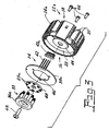
- Fig. 7 is a sectional view of an installed embodiment of the invention.
- Fig. 8 is an enlarged view of a light guide-LED interface
- Fig. 9 is a sectional view of an alternate embodiment of light guide.
- Fig. 10 is a sectional view of an additional embodiment of a light guide.
- FIGs. 1-3 first and second embodiments 10 (Fig. 2) and 10a (Fig. 3) of an LED light source comprising: a heat sink 12 having a body 14 with a front surface 16 and a rear surface 18, the rear surface 18 being provided with heat dissipaters 20 in the form of radial fins.
- the front surface 16 includes a pocket 22 for the receipt of components 24 including at least one LED 25, 25a and electrical circuitry therefor (not shown).
- Common to both embodiments is a housing 26 having a flange 28 and a tubular projection 30 as shown in Fig, 1.
- a sealing gasket 31 can also be provided for supplying an environmental seal when the LED light source 10 is mounted.
- the flange 28 is fitted into the pocket 22 to fix the components 24 in the heat sink 12 in a manner to be described hereinafter.
- the LEDs 25 are preferably of the type known as Advanced Power TOPLED®s (APT).
- the LEDs 25a are preferably of the type known as chip-on-board, such as OSTAR®. Both the APT and OSTAR® LEDs are available from OSRAM OPTO Semiconductors GmbH, Regensburg, Germany
- an optical light guide 32 of a suitable transparent material such as acrylic or polycarbonate has at least one light pipe 34 surrounding a core 35.
- the number of light pipes and LEDs is eight; however, other numbers of LEDs can commonly be supported on a central core 35 formed with a bore 39 for a threaded or similar attachment.
- the optical light guide 32 is positioned in the tubular projection 30 so that each of the at least one light pipes 34, each having a light input end 34a, is fixed in light gathering alignment with a corresponding one of the at least one LEDs 25 in a one-to-one relationship. The relationship is shown most clearly in Fig. 8.
- Slots 32a are formed between the light pipes 34 and supports 35a to allow flexing of the light pipes 34 relative to each other and to the central core 35 to accommodate tolerances in packaging of the LEDs 25.
- a protuberance 58 therein extends from the bottom of the optical light guide 32 and has bore 37a therein.
- Each of the at least one light pipes 34 has a light output end 36 opposite the light input ends 34a formed to direct light to a suitable location, such as to an optic 37.
- An optic 37 is partially shown in Figs. 4 and 5 and more completely shown in Figs. 6 and 7.
- the components 24 additionally include a printed circuit board 38 (PCB) that carries the electrical circuitry (not shown) and an adjustment washer 40 centrally positioned with the printed circuit board 38.
- the printed circuit board 38 has a central aperture 38a and a plurality of connectors 42 positioned thereon to extend beyond the printed circuit board for connection to a power source.
- the connectors 42 project through an electrically insulating washer 42a that is fitted into a compartment 42b in the heat sink 12.
- the electrically insulating washer 42a is fitted into compartment 42b in the heat sink 12 and the printed circuit board 38 is placed in pocket 22 with the connectors 42 penetrating the insulating washer 42a and extending therefrom for subsequent attachment to a power source.
- Washer 40 is positioned on the PCB and the light guide 32 is fitted thereon with the protuberance 58 extending through the adjustment washer 40, the aperture 38a and into a well 60 formed in the center of pocket 22.
- a bolt 62 is inserted through an aperture in the protuberance 58 and into engagement with a treaded portion in the well 60.
- the housing 26 is then applied with the flange 28 fitted into the pocket 22 and the tubular projection 30 surrounding the light guide 32.
- Fasteners 66 which can be in the form of threaded bolts, are inserted from the base of the heat sink 12 and engage threaded portions 68 formed on the underside of the flange 28, as seen most clearly in Figs. 4 and 5.
- a heat sink 12a includes a central boss 44 in the pocket 22 and a PCB 38a includes a central aperture 46 that surrounds the boss 44.
- a metal-clad printed circuit board 48 mounts at least one LEDs 25 and is positioned on the boss 44.
- the LEDs 25a are preferably of the type known as chip-on-board, such as the aforementioned OSTAR® and, therefore, a light guide 33 does not require the flexing slots and can be solid because it is not necessary to accommodate varying tolerances that may occur in die packages since those packages are not present. Also, the adjustment washer is eliminated.
- the LED light source 10 is ideally suited for use with an indicator 50 (Fig. 7) that comprises a reception area 52 having a first surface 52a and a second, opposite surface 52b formed in a body 54 and having a substantially centrally located light source receiving aperture 56 formed therein.
- the body 54 can be a portion of a vehicle, such as rear quarter panel, and the indicator 50 can be a taillight or stoplight.
- An input end of optic 37 is operatively mounted in the reception area 52 with respect to the first surface 52a.
- the optic 37 has a number N of optic input windows 37a to mate with the corresponding output windows of the LED light source 10.
- the LED light source 10 is replaceably mounted with respect to the second surface 52b, for example, by rotating the unit to engage the lugs 70 formed on the tubular projection 30, with suitable engaging slots formed with the second, opposite surface 52b. This arrangement is fairly standard in the automotive industry.
- the optic 37 has a plurality of outputs 37b extending away from a centerpoint; however, virtually any configuration can be provided so long as the input windows of the optic match the output windows of the light guide. Additionally, if desired, either or both sides of the ends of the legs can be provided with suitable lensing to increase or otherwise modify the light output.
- An added advantage of this system is the elimination of a reflectorized surface, allowing the reception area 52 to have the same color as the body 54 and vastly increasing design options.
- Fig. 8 Critical to the use of any system involving LEDs (or other light sources) and optics is the alignment of the light source and optic to maximize the useful light output.
- Fig. 8 Another approach is shown in Fig. 8 wherein an LED die 100 is provided with internal projections 102 surrounding the LED.
- Such internal projections can have a height that is very accurately controlled and thus allow accurate positioning of the abutted light input window 34a of a light pipe 34 in relation to the LED by allowing contact to be made between the input window 34a and the projections 102.
- FIG. 9 there is shown an alternate light guide 33a wherein output windows 36b are formed at an angle relative to the input windows 34a, such that light emanating therefrom is focused at a point P above the light guide.
- the light focused at point P can be directed into an optic or lens or any other suitable device.
- a light guide 32a similarly can be provided with angled output windows 36b to focus the emanated light upon a point P.
Abstract
Description
- This application claims priority from Provisional Patent Application No.
60/720,395, filed September 26, 2005 - This invention relates generally to light sources and more particularly to light sources employing light emitting diodes (LED or LEDs). Still more particularly, it relates to LED light sources for use with direct optics. Further, it relates to LED light sources having a specific application to indicator lights for vehicles.
- Competitive pressures in industry, particularly the automotive industry, dictate a necessity to make light sources as small and economical as possible. This saves material costs, and can improve optical imaging. In competition with these needs, large fields areas may need to be illuminated, and with vehicle illumination, a substantial visual image is need on the surface of the vehicle to mark the presence of the vehicle. These goals have been met in the past by the use of relatively large incandescent lamp and reflector systems. The advent of solid-state lighting, such as light emitting diodes, has pointed in the direction of improving these systems by drastically reducing the size of the light source while increasing their longevity; however, there is still a need to spread beam-forming illumination over a broad area to better illuminate the vehicle. It would be an advance in the art if such a system could be provided without the necessity of using a reflector. It would be a further advance in the art to provide a lighting system that can utilize replacement light sources. It would be a still further advance in the art to provide a combination solid-state light source with a direct view optic that can be customer designed in a variety of displays.
- It is, therefore, an object of the invention to obviate the disadvantages of the prior art.
- It is yet another object of the invention to enhance light sources.
- Still another object of the invention is the enhancement of automotive indicators.
- These objects are accomplished, in one aspect of the invention, by an LED light source comprising: a body with a front surface and a rear surface, the front surface including a pocket for the receipt of components, the components including at least one LEDs and electrical circuitry therefor; a housing fitted into the pocket in a manner to fix the components in the heat sink; and an optical light guide having at least one light pipes positioned in the tubular projection, each of the at least one light pipes having a light input end fixed in light gathering alignment with the at least one LEDs in a one-to-one relationship.
- The objects are accomplished in another aspect of the invention by an indicator comprising: a reception area having a first surface and a second, opposite surface formed in a body and having a substantially centrally located light source receiving aperture formed therein; an optic operatively mounted in the reception area with respect to the first surface, the optic having at least one optic input windows; and an LED light source replaceably mounted with respect to the second surface, the LED light source including an optical light guide having at least one light pipes with at least one output ends operatively connected to the at least one optic input windows.
- The light source of this invention is small and economical. It is structured to physically fit in locations designed for the standard S8 lamp socket and, when combined with the custom optic, eliminates the need for reflectorized coatings.
- Fig. 1 is an exploded, perspective view of a housing that can be used with an embodiment of the invention;
- Fig. 2 is an exploded, perspective view of a first embodiment of the invention;
- Fig. 3 is an exploded, perspective view of an alternate embodiment of the invention;
- Fig. 4 is an enlarged, sectional view of the embodiment of Fig. 2;
- Fig. 5 is an enlarged, sectional view of the embodiment of Fig. 3;
- Fig. 6 is a plan view of an optic that can be used with an embodiment of the invention;
- Fig. 7 is a sectional view of an installed embodiment of the invention;
- Fig. 8 is an enlarged view of a light guide-LED interface;
- Fig. 9 is a sectional view of an alternate embodiment of light guide; and
- Fig. 10 is a sectional view of an additional embodiment of a light guide.
- For a better understanding of the present invention, together with other and further objects, advantages and capabilities thereof, reference is made to the following disclosure and appended claims taken in conjunction with the above-described drawings.
- Referring now to the drawings with greater particularity, there is shown in Figs. 1-3 first and second embodiments 10 (Fig. 2) and 10a (Fig. 3) of an LED light source comprising: a
heat sink 12 having abody 14 with afront surface 16 and arear surface 18, therear surface 18 being provided withheat dissipaters 20 in the form of radial fins. Thefront surface 16 includes apocket 22 for the receipt ofcomponents 24 including at least oneLED housing 26 having aflange 28 and atubular projection 30 as shown in Fig, 1. Asealing gasket 31 can also be provided for supplying an environmental seal when theLED light source 10 is mounted. Theflange 28 is fitted into thepocket 22 to fix thecomponents 24 in theheat sink 12 in a manner to be described hereinafter. In the embodiment shown in Figs. 2 and 4 theLEDs 25 are preferably of the type known as Advanced Power TOPLED®s (APT). In the embodiment shown in Figs. 3 and 5 theLEDs 25a are preferably of the type known as chip-on-board, such as OSTAR®. Both the APT and OSTAR® LEDs are available from OSRAM OPTO Semiconductors GmbH, Regensburg, Germany - Referring now to the specific embodiment of Fig, 2, an
optical light guide 32 of a suitable transparent material such as acrylic or polycarbonate has at least onelight pipe 34 surrounding acore 35. In all of the preferred embodiments disclosed herein the number of light pipes and LEDs is eight; however, other numbers of LEDs can commonly be supported on acentral core 35 formed with abore 39 for a threaded or similar attachment. Theoptical light guide 32 is positioned in thetubular projection 30 so that each of the at least onelight pipes 34, each having alight input end 34a, is fixed in light gathering alignment with a corresponding one of the at least oneLEDs 25 in a one-to-one relationship. The relationship is shown most clearly in Fig. 8.Slots 32a are formed between thelight pipes 34 and supports 35a to allow flexing of thelight pipes 34 relative to each other and to thecentral core 35 to accommodate tolerances in packaging of theLEDs 25. Aprotuberance 58 therein extends from the bottom of theoptical light guide 32 and has bore 37a therein. - Each of the at least one
light pipes 34 has alight output end 36 opposite thelight input ends 34a formed to direct light to a suitable location, such as to an optic 37. Anoptic 37 is partially shown in Figs. 4 and 5 and more completely shown in Figs. 6 and 7. - The
components 24 additionally include a printed circuit board 38 (PCB) that carries the electrical circuitry (not shown) and an adjustment washer 40 centrally positioned with the printedcircuit board 38. The printedcircuit board 38 has acentral aperture 38a and a plurality ofconnectors 42 positioned thereon to extend beyond the printed circuit board for connection to a power source. Theconnectors 42 project through an electrically insulatingwasher 42a that is fitted into a compartment 42b in theheat sink 12. - For assembly of the
LED light source 10, the electrically insulatingwasher 42a is fitted into compartment 42b in theheat sink 12 and the printedcircuit board 38 is placed inpocket 22 with theconnectors 42 penetrating theinsulating washer 42a and extending therefrom for subsequent attachment to a power source.Washer 40 is positioned on the PCB and thelight guide 32 is fitted thereon with theprotuberance 58 extending through theadjustment washer 40, theaperture 38a and into a well 60 formed in the center ofpocket 22. Abolt 62 is inserted through an aperture in theprotuberance 58 and into engagement with a treaded portion in thewell 60. Controlling the amount of penetration of thebolt 62 into thewell 60, in combination with theflexing slots 32a formed between thepipes 34, assures that theinput windows 34a are closely abutted to a respective LED die without damage to the LED or light guide, thus insuring maximum light input into thelight guide 32. - The
housing 26 is then applied with theflange 28 fitted into thepocket 22 and thetubular projection 30 surrounding thelight guide 32.Fasteners 66, which can be in the form of threaded bolts, are inserted from the base of theheat sink 12 and engage threadedportions 68 formed on the underside of theflange 28, as seen most clearly in Figs. 4 and 5. - Referring now to Figs. 3 and 5, a
heat sink 12a includes acentral boss 44 in thepocket 22 and a PCB 38a includes a central aperture 46 that surrounds theboss 44. A metal-clad printedcircuit board 48 mounts at least oneLEDs 25 and is positioned on theboss 44. In this embodiment theLEDs 25a are preferably of the type known as chip-on-board, such as the aforementioned OSTAR® and, therefore, alight guide 33 does not require the flexing slots and can be solid because it is not necessary to accommodate varying tolerances that may occur in die packages since those packages are not present. Also, the adjustment washer is eliminated. - The
LED light source 10 is ideally suited for use with an indicator 50 (Fig. 7) that comprises areception area 52 having a first surface 52a and a second, opposite surface 52b formed in a body 54 and having a substantially centrally located lightsource receiving aperture 56 formed therein. The body 54 can be a portion of a vehicle, such as rear quarter panel, and theindicator 50 can be a taillight or stoplight. - An input end of
optic 37 is operatively mounted in thereception area 52 with respect to the first surface 52a. The optic 37 has a number N ofoptic input windows 37a to mate with the corresponding output windows of theLED light source 10. - The
LED light source 10 is replaceably mounted with respect to the second surface 52b, for example, by rotating the unit to engage thelugs 70 formed on thetubular projection 30, with suitable engaging slots formed with the second, opposite surface 52b. This arrangement is fairly standard in the automotive industry. - In the embodiment shown in Figs. 6 and 7 the optic 37 has a plurality of outputs 37b extending away from a centerpoint; however, virtually any configuration can be provided so long as the input windows of the optic match the output windows of the light guide. Additionally, if desired, either or both sides of the ends of the legs can be provided with suitable lensing to increase or otherwise modify the light output.
- An added advantage of this system is the elimination of a reflectorized surface, allowing the
reception area 52 to have the same color as the body 54 and vastly increasing design options. - Critical to the use of any system involving LEDs (or other light sources) and optics is the alignment of the light source and optic to maximize the useful light output. One way in which this can be accomplished is via the adjustment screw and adjustment washer described above. Another approach is shown in Fig. 8 wherein an LED die 100 is provided with
internal projections 102 surrounding the LED. Such internal projections can have a height that is very accurately controlled and thus allow accurate positioning of the abuttedlight input window 34a of alight pipe 34 in relation to the LED by allowing contact to be made between theinput window 34a and theprojections 102. - Referring now to Fig. 9, there is shown an alternate light guide 33a wherein
output windows 36b are formed at an angle relative to theinput windows 34a, such that light emanating therefrom is focused at a point P above the light guide. The light focused at point P can be directed into an optic or lens or any other suitable device. - Referring now to Fig. 10, a
light guide 32a similarly can be provided withangled output windows 36b to focus the emanated light upon a point P. - While there have been shown and described what are at present considered to be the preferred embodiments of the invention, it will be apparent to those skilled in the art that various changes and modifications can be made herein without departing from the scope of the invention as defined by the appended claims.
Claims (17)
- An LED light source comprising:a body with a front surface and a rear surface, said front surface including a pocket for the receipt of components said components including at least one LED and electrical circuitry therefor;a housing fitted into said pocket in a manner to fix said components in said body; andan optical light guide having at least one light pipe positioned in said tubular projection, each of said at least one light pipes having a light input end fixed in light gathering alignment with said at least one LED in a one-to-one relationship.
- The LED light source of Claim 1 wherein each of said at least one light pipes has a light output end opposite said light input ends formed to direct light to an optic.
- The LED light source of Claim 1 wherein said components additionally include a printed circuit board that carries said electrical circuitry and an adjustment washer centrally located on said printed circuit board and a plurality of connectors positioned on said printed circuit board to extend beyond said printed circuit board for connection to a power source.
- The LED light source of Claim 1 wherein said pocket includes a central boss, said printed circuit board includes a central aperture that surrounds said boss, and a metal-clad printed circuit board that mounts said at least one LEDs positioned on said boss.
- An indicator comprising:a reception area having a first surface and a second, opposite surface formed in a body and having a substantially centrally located light source receiving aperture formed therein;an optic operatively mounted in said reception area with respect to said first surface, said optic having at least one optic input window; andan LED light source mounted with respect to said second surface, said LED light source including an optical light guide having at least one light pipe having at least one output end operatively connected to said at least one optic input window.
- The indicator of Claim 5 wherein said body comprises a portion of a vehicle and said reception area comprises a depression.
- The indicator of Claim 6 wherein said body has a substantially non-reflective color and said reception area has the same non-reflective color.
- An optical light guide comprising:a central core;a plurality of light pipes;a plurality of light pipe supports extending from said central core, each of said plurality of light pipe supports supporting a respective light pipe, each light pipe being formed from a light transmissive material and having a light input window, a light output window, and an internally reflective wall extending from the input window to the output window.
- The optical light guide of Claim 8 wherein said central core includes a mounting bore.
- The optical light guide of Claim 8 wherein said input windows are substantially co-planar.
- The optical light guide of Claim 8 wherein said output windows are substantially co-planar.
- The optical light guide of Claim 8 wherein at least one of the light pipes is flexibly mounted with respect to a corresponding light pipe support.
- The optical light guide of Claim 8 wherein at least one of said light pipe supports is flexibly mounted with respect to said central core.
- The optical light guide of Claim 8 wherein said light pipes each have an axis extending from an input window to a respective output window and said axes are parallel.
- The optical light guide of Claim 8 wherein said light pipes each have an axis extending from said input window to said output window and the light from the output windows converges at a point P.
- The optical light guide of Claim 8 wherein the light pipes are radially arrayed about a common axis for the core.
- The optical light guide of Claim 8 wherein a plurality of the light pipes, a plurality of the corresponding light guide supports and the core are formed as a unitary piece.
Applications Claiming Priority (2)
| Application Number | Priority Date | Filing Date | Title |
|---|---|---|---|
| US72039505P | 2005-09-26 | 2005-09-26 | |
| US11/477,731 US7588359B2 (en) | 2005-09-26 | 2006-06-29 | LED lamp with direct optical coupling in axial arrangement |
Publications (3)
| Publication Number | Publication Date |
|---|---|
| EP1767967A2 true EP1767967A2 (en) | 2007-03-28 |
| EP1767967A3 EP1767967A3 (en) | 2007-05-30 |
| EP1767967B1 EP1767967B1 (en) | 2013-03-13 |
Family
ID=37517219
Family Applications (1)
| Application Number | Title | Priority Date | Filing Date |
|---|---|---|---|
| EP06017804A Expired - Fee Related EP1767967B1 (en) | 2005-09-26 | 2006-08-25 | Led lamp with direct optical coupling to an optical light guide having purality of light pipes in axial arrangement |
Country Status (8)
| Country | Link |
|---|---|
| US (1) | US7588359B2 (en) |
| EP (1) | EP1767967B1 (en) |
| JP (1) | JP5073999B2 (en) |
| KR (1) | KR101186440B1 (en) |
| CN (1) | CN1955774B (en) |
| AU (1) | AU2006203473B2 (en) |
| CA (1) | CA2553533C (en) |
| TW (1) | TWI387126B (en) |
Cited By (20)
| Publication number | Priority date | Publication date | Assignee | Title |
|---|---|---|---|---|
| DE102007018698A1 (en) * | 2007-04-18 | 2008-10-23 | Bayerische Motoren Werke Aktiengesellschaft | Vehicle headlight module, has set of LEDs carried by carrier device, and ventilator coupled with carrier device such that cooling air sucked by ventilator flows through cavity of carrier device |
| EP2020567A1 (en) * | 2007-08-01 | 2009-02-04 | Osram-Sylvania Inc. | Direct view LED lamp with snap fit housing |
| EP2177825A1 (en) * | 2008-08-28 | 2010-04-21 | Toshiba Lighting & Technology Corporation | Lighting apparatus having light emitting diodes for light source |
| ITMC20090208A1 (en) * | 2009-10-07 | 2011-04-08 | Micronasa Di Patarchi Alberto | LED SPOTLIGHT |
| US7993033B2 (en) | 2008-05-22 | 2011-08-09 | Toshiba Lighting & Technology Corporation | Reflector and lighting apparatus comprising reflector |
| EP2357395A1 (en) * | 2010-02-05 | 2011-08-17 | Odelo GmbH | Light unit with light guide |
| US8128263B2 (en) | 2008-09-16 | 2012-03-06 | Toshiba Lighting & Technology Corporation | Light source unit and lighting apparatus having light-emitting diodes for light source |
| WO2012039658A1 (en) * | 2010-09-22 | 2012-03-29 | Enercomp Ab | Led lamp |
| EP2578920A1 (en) * | 2010-05-26 | 2013-04-10 | S.K.G. Co., Ltd. | Illumination device |
| US8491163B2 (en) | 2009-09-25 | 2013-07-23 | Toshiba Lighting & Technology Corporation | Lighting apparatus |
| WO2013127632A1 (en) * | 2012-02-27 | 2013-09-06 | Osram Gmbh | Lighting device |
| CN103307573A (en) * | 2012-03-13 | 2013-09-18 | 欧司朗股份有限公司 | Radiator and illuminating device provided with same |
| US8545051B2 (en) | 2008-05-30 | 2013-10-01 | Toshiba Lighting & Technology Corporation | Lighting apparatus with heat conductive substrate |
| EP2886939A3 (en) * | 2013-12-20 | 2015-07-15 | Toshiba Lighting & Technology Corporation | Lighting device and lighting device set |
| FR3025863A1 (en) * | 2014-09-16 | 2016-03-18 | Valeo Vision | LUMINOUS MODULE COMPRISING A MULTI-SOURCE OPTICAL LENS |
| USRE46325E1 (en) | 2005-05-02 | 2017-02-28 | Kavo Dental Technologies, Llc | LED-based dental exam lamp with variable chromaticity |
| US10132484B2 (en) | 2005-05-02 | 2018-11-20 | Kavo Dental Technologies, Llc | LED-based dental exam lamp |
| US10754075B1 (en) | 2019-04-09 | 2020-08-25 | Signify Holding B.V. | Light assembly having a ring-shaped lightguide with a plurality of light incident portions |
| DE102009023645B4 (en) | 2009-05-25 | 2021-09-30 | Automotive Lighting Reutlingen Gmbh | LED module |
| EP4174367A1 (en) * | 2021-10-29 | 2023-05-03 | Valeo Vision | Optical module of a lighting device of a motor vehicle |
Families Citing this family (79)
| Publication number | Priority date | Publication date | Assignee | Title |
|---|---|---|---|---|
| US20070035951A1 (en) * | 2005-08-12 | 2007-02-15 | Yin-Hsiu Tseng | Lighting equipment for a kitchen ventilator |
| US20070253201A1 (en) * | 2006-04-27 | 2007-11-01 | Cooper Technologies Company | Lighting fixture and method |
| US7562995B1 (en) | 2006-08-25 | 2009-07-21 | Jonathan Levine | Adjustable lighting device |
| US7699492B2 (en) * | 2006-12-08 | 2010-04-20 | Levine Jonathan E | Lighting device with clip |
| EP1975710B1 (en) | 2007-03-30 | 2013-10-23 | FUJIFILM Corporation | Plate-making method of lithographic printing plate precursor |
| US7591572B1 (en) | 2007-04-11 | 2009-09-22 | Levine Jonathan E | Compact lighting device |
| US7717597B2 (en) * | 2007-04-16 | 2010-05-18 | Magna International Inc. | Semiconductor light engine using polymer light pipes and lighting systems constructed with the light engine |
| US20090016074A1 (en) * | 2007-07-09 | 2009-01-15 | Magna International Inc. | Semiconductor light engine using glass light pipes |
| CN100453896C (en) * | 2007-10-16 | 2009-01-21 | 东莞勤上光电股份有限公司 | LED fluorescent tube |
| TWM334272U (en) * | 2007-12-04 | 2008-06-11 | Cooler Master Co Ltd | An LED lighting device |
| US8356920B2 (en) * | 2007-12-12 | 2013-01-22 | Levine Jonathan E | Lighting device |
| US8018136B2 (en) * | 2008-02-28 | 2011-09-13 | Tyco Electronics Corporation | Integrated LED driver for LED socket |
| US7942563B2 (en) * | 2008-02-29 | 2011-05-17 | Tyco Electronics Corporation | LED with light pipe assembly |
| US20110096562A1 (en) * | 2008-03-26 | 2011-04-28 | Lambert Chad D | Fog Lamp and the Like Employing Semiconductor Light Sources |
| CA2664963A1 (en) * | 2008-05-01 | 2009-11-01 | Magna International Inc. | Hotspot cutoff d-optic |
| US7731386B2 (en) * | 2008-05-24 | 2010-06-08 | Levine Jonathan E | Lighting device |
| US20100033960A1 (en) * | 2008-08-06 | 2010-02-11 | Levine Jonathan E | Lighting device |
| US7952114B2 (en) | 2008-09-23 | 2011-05-31 | Tyco Electronics Corporation | LED interconnect assembly |
| US7922364B2 (en) | 2009-03-10 | 2011-04-12 | Osram Sylvania, Inc. | LED lamp assembly |
| DE102009014485A1 (en) * | 2009-03-23 | 2010-09-30 | Ledon Lighting Jennersdorf Gmbh | LED light |
| US20100283369A1 (en) * | 2009-05-05 | 2010-11-11 | Yi-jin Industrial Co., Ltd. | LED bulb and lamp holder thereof |
| JP5303358B2 (en) * | 2009-05-25 | 2013-10-02 | 株式会社小糸製作所 | Vehicle lighting |
| JP2010267600A (en) * | 2009-07-08 | 2010-11-25 | Yi-Jin Industrial Co Ltd | Led bulb and its lamp cover |
| US8596825B2 (en) * | 2009-08-04 | 2013-12-03 | 3M Innovative Properties Company | Solid state light with optical guide and integrated thermal guide |
| WO2011028805A2 (en) * | 2009-09-01 | 2011-03-10 | Savenergy Inc. | Cooled led lighting assemblies |
| CN102141209A (en) * | 2010-02-03 | 2011-08-03 | 富准精密工业(深圳)有限公司 | Light-emitting diode lamp |
| US10359151B2 (en) * | 2010-03-03 | 2019-07-23 | Ideal Industries Lighting Llc | Solid state lamp with thermal spreading elements and light directing optics |
| CA2740825C (en) | 2010-05-23 | 2014-03-18 | Rab Lighting, Inc. | Led housing with heat transfer sink |
| US8476837B2 (en) | 2010-07-02 | 2013-07-02 | 3M Innovative Properties Company | Transistor ladder network for driving a light emitting diode series string |
| KR101742678B1 (en) * | 2010-09-17 | 2017-06-01 | 엘지이노텍 주식회사 | Lamp apparatus |
| GB2483852A (en) * | 2010-09-21 | 2012-03-28 | Power Data Comm Co Ltd | Back light plate with juxtaposed light bars |
| US8487518B2 (en) * | 2010-12-06 | 2013-07-16 | 3M Innovative Properties Company | Solid state light with optical guide and integrated thermal guide |
| TWI406058B (en) | 2010-12-20 | 2013-08-21 | Au Optronics Corp | Backlight module |
| KR101812800B1 (en) | 2011-03-02 | 2017-12-27 | 엘지이노텍 주식회사 | Lighting device |
| TWM415245U (en) * | 2011-06-30 | 2011-11-01 | Chun Kuang Optics Corp | Optic element and lighting device comprising the optic element |
| US8657465B2 (en) | 2011-08-31 | 2014-02-25 | Osram Sylvania Inc. | Light emitting diode lamp assembly |
| WO2013054225A1 (en) * | 2011-10-10 | 2013-04-18 | Koninklijke Philips Electronics N.V. | Luminaire arrangement |
| US8926131B2 (en) | 2012-05-08 | 2015-01-06 | 3M Innovative Properties Company | Solid state light with aligned light guide and integrated vented thermal guide |
| KR102172743B1 (en) * | 2012-05-29 | 2020-11-02 | 이치코 고교가부시키가이샤 | Vehicular lighting instrument semiconductor light source light source unit and vehicular lighting instrument |
| US8807808B2 (en) | 2012-07-26 | 2014-08-19 | Ronald E. BOYD, JR. | LED retrofit vehicle tail lamp |
| US10563850B2 (en) | 2015-04-22 | 2020-02-18 | DMF, Inc. | Outer casing for a recessed lighting fixture |
| US9964266B2 (en) | 2013-07-05 | 2018-05-08 | DMF, Inc. | Unified driver and light source assembly for recessed lighting |
| US11060705B1 (en) | 2013-07-05 | 2021-07-13 | DMF, Inc. | Compact lighting apparatus with AC to DC converter and integrated electrical connector |
| US10139059B2 (en) | 2014-02-18 | 2018-11-27 | DMF, Inc. | Adjustable compact recessed lighting assembly with hangar bars |
| US11255497B2 (en) | 2013-07-05 | 2022-02-22 | DMF, Inc. | Adjustable electrical apparatus with hangar bars for installation in a building |
| US11435064B1 (en) | 2013-07-05 | 2022-09-06 | DMF, Inc. | Integrated lighting module |
| US10753558B2 (en) | 2013-07-05 | 2020-08-25 | DMF, Inc. | Lighting apparatus and methods |
| US10551044B2 (en) | 2015-11-16 | 2020-02-04 | DMF, Inc. | Recessed lighting assembly |
| US9215793B2 (en) | 2013-11-08 | 2015-12-15 | Abl Ip Holding Llc | System and method for connecting LED devices |
| US9103520B1 (en) | 2014-04-18 | 2015-08-11 | Osram Sylvania Inc. | Combination turn and tail multi-color LED lamp |
| TWI535972B (en) * | 2014-11-26 | 2016-06-01 | 中強光電股份有限公司 | Vehicle lighting device |
| US20160238205A1 (en) * | 2015-02-13 | 2016-08-18 | Concorde International | Collapsible Shelter Light |
| CN104791683A (en) * | 2015-04-07 | 2015-07-22 | 汪坚 | LED illumination lamp used for stroller |
| CA3102022C (en) | 2015-05-29 | 2023-04-25 | DMF, Inc. | Lighting module for recessed lighting systems |
| USD851046S1 (en) | 2015-10-05 | 2019-06-11 | DMF, Inc. | Electrical Junction Box |
| CN105674149A (en) * | 2016-01-27 | 2016-06-15 | 徐存然 | Lamp support of pond searchlight |
| CN105650567A (en) * | 2016-01-27 | 2016-06-08 | 苏州泓启业亿电子科技有限公司 | LED illumination indicating system of electric vehicle |
| US10488000B2 (en) | 2017-06-22 | 2019-11-26 | DMF, Inc. | Thin profile surface mount lighting apparatus |
| WO2018237294A2 (en) | 2017-06-22 | 2018-12-27 | DMF, Inc. | Thin profile surface mount lighting apparatus |
| USD905327S1 (en) | 2018-05-17 | 2020-12-15 | DMF, Inc. | Light fixture |
| US11067231B2 (en) | 2017-08-28 | 2021-07-20 | DMF, Inc. | Alternate junction box and arrangement for lighting apparatus |
| CN111670322B (en) | 2017-11-28 | 2022-04-26 | Dmf股份有限公司 | Adjustable hanger rod assembly |
| WO2019133669A1 (en) | 2017-12-27 | 2019-07-04 | DMF, Inc. | Methods and apparatus for adjusting a luminaire |
| US10914431B2 (en) * | 2017-12-31 | 2021-02-09 | Google Llc | Smart-home device light rings with tapered transmissive sections for uniform output |
| EP3531247B1 (en) * | 2018-02-27 | 2023-03-29 | HTC Corporation | Traceable optical device |
| USD877957S1 (en) | 2018-05-24 | 2020-03-10 | DMF Inc. | Light fixture |
| WO2019241198A1 (en) | 2018-06-11 | 2019-12-19 | DMF, Inc. | A polymer housing for a recessed lighting system and methods for using same |
| USD903605S1 (en) | 2018-06-12 | 2020-12-01 | DMF, Inc. | Plastic deep electrical junction box |
| WO2020072592A1 (en) | 2018-10-02 | 2020-04-09 | Ver Lighting Llc | A bar hanger assembly with mating telescoping bars |
| USD901398S1 (en) | 2019-01-29 | 2020-11-10 | DMF, Inc. | Plastic deep electrical junction box |
| US11041615B2 (en) * | 2019-01-29 | 2021-06-22 | Anthem One, Inc. | Light emitting diode (LED) lighting system |
| USD1012864S1 (en) | 2019-01-29 | 2024-01-30 | DMF, Inc. | Portion of a plastic deep electrical junction box |
| USD864877S1 (en) | 2019-01-29 | 2019-10-29 | DMF, Inc. | Plastic deep electrical junction box with a lighting module mounting yoke |
| USD966877S1 (en) | 2019-03-14 | 2022-10-18 | Ver Lighting Llc | Hanger bar for a hanger bar assembly |
| US11073259B2 (en) | 2019-08-30 | 2021-07-27 | Fluence Bioengineering, Inc. | Horticultural luminaire with a convex endcap |
| WO2021051101A1 (en) | 2019-09-12 | 2021-03-18 | DMF, Inc. | Miniature lighting module and lighting fixtures using same |
| CA3124976A1 (en) | 2020-07-17 | 2022-01-17 | DMF, Inc. | Polymer housing for a lighting system and methods for using same |
| USD990030S1 (en) | 2020-07-17 | 2023-06-20 | DMF, Inc. | Housing for a lighting system |
| US11585517B2 (en) | 2020-07-23 | 2023-02-21 | DMF, Inc. | Lighting module having field-replaceable optics, improved cooling, and tool-less mounting features |
Citations (1)
| Publication number | Priority date | Publication date | Assignee | Title |
|---|---|---|---|---|
| EP1031464A2 (en) | 1999-02-24 | 2000-08-30 | Diehl Luftfahrt Elektronik GmbH | Device for the illumination of a room, a body or a surface |
Family Cites Families (28)
| Publication number | Priority date | Publication date | Assignee | Title |
|---|---|---|---|---|
| GB1310790A (en) | 1971-11-25 | 1973-03-21 | Probert P | Light intensity indicator |
| DE2742031B2 (en) | 1977-09-19 | 1979-09-13 | Robert Bosch Gmbh, 7000 Stuttgart | Gear changing device for vehicle powershift transmissions |
| US4630177A (en) * | 1984-10-15 | 1986-12-16 | Kohorn H Von | Light-conductive device for illuminating centripetally viewed three-dimensional objects |
| US5039832A (en) * | 1989-07-05 | 1991-08-13 | Otis Elevator Company | Touch button light ring system |
| US5436805A (en) * | 1992-10-29 | 1995-07-25 | Hughes Aircraft Company | Thermally insulated distributed light network from a central light source |
| DE19547861A1 (en) * | 1995-12-21 | 1997-06-26 | Reitter & Schefenacker Gmbh | Rear light for vehicles, preferably motor vehicles |
| TW402856B (en) * | 1996-12-26 | 2000-08-21 | Palite Corp | LED illuminator |
| US20010002219A1 (en) * | 1997-06-30 | 2001-05-31 | Shin-Etsu Chemical Co., Ltd. | Multi-branching optical coupler |
| US6304693B1 (en) * | 1999-12-02 | 2001-10-16 | Fiberstars Incorporated | Efficient arrangement for coupling light between light source and light guide |
| US6527411B1 (en) | 2000-08-01 | 2003-03-04 | Visteon Corporation | Collimating lamp |
| EP1298384B1 (en) * | 2001-09-27 | 2004-03-03 | Seat, S.A. | Automobile optical group module |
| JP2004247312A (en) * | 2001-11-09 | 2004-09-02 | Ccs Inc | Light source device |
| JP2004047351A (en) | 2002-07-15 | 2004-02-12 | Koito Mfg Co Ltd | Vehicular lighting fixture |
| US7182597B2 (en) * | 2002-08-08 | 2007-02-27 | Kerr Corporation | Curing light instrument |
| US6942373B2 (en) * | 2003-03-14 | 2005-09-13 | Fiberstars Incorporated | Fiberoptic lighting system with shaped collector for efficiency |
| DE10312950A1 (en) | 2003-03-22 | 2004-10-14 | Lear Automotive Electronics Gmbh | Illumination module with at least one light source in lamp housing in car, with light source spatially separated from module, with light source light guided by optical fibre to light outlet in module in lamp housing |
| US20050201100A1 (en) * | 2003-09-08 | 2005-09-15 | Cassarly William J. | Led lighting assembly |
| US7387402B1 (en) * | 2003-11-13 | 2008-06-17 | Lui Phillip Chun Wai | Multiple light LED flashlight |
| JP2005158362A (en) * | 2003-11-21 | 2005-06-16 | Stanley Electric Co Ltd | Lighting fixture for vehicle |
| US7250611B2 (en) | 2003-12-02 | 2007-07-31 | 3M Innovative Properties Company | LED curing apparatus and method |
| DE10360896A1 (en) | 2003-12-19 | 2005-07-21 | Robert Bosch Gmbh | Function Display lighting device |
| JP2005227050A (en) | 2004-02-12 | 2005-08-25 | Calsonic Kansei Corp | Indicating instrument for vehicle |
| US7217022B2 (en) * | 2004-08-31 | 2007-05-15 | Opto Technology, Inc. | Optic fiber LED light source |
| US7261452B2 (en) | 2004-09-22 | 2007-08-28 | Osram Sylvania Inc. | LED headlight |
| TWI249257B (en) * | 2004-09-24 | 2006-02-11 | Epistar Corp | Illumination apparatus |
| US7618171B2 (en) | 2004-10-21 | 2009-11-17 | Osram Sylvania Inc. | Light emitting diode module for automotive headlamp |
| JP4731494B2 (en) * | 2004-11-30 | 2011-07-27 | シーシーエス株式会社 | Light irradiation device |
| US7375382B2 (en) * | 2005-06-23 | 2008-05-20 | Osram Sylvania, Inc. | Direct optical light guide |
-
2006
- 2006-06-29 US US11/477,731 patent/US7588359B2/en not_active Expired - Fee Related
- 2006-07-26 CA CA2553533A patent/CA2553533C/en not_active Expired - Fee Related
- 2006-08-14 AU AU2006203473A patent/AU2006203473B2/en not_active Ceased
- 2006-08-25 EP EP06017804A patent/EP1767967B1/en not_active Expired - Fee Related
- 2006-08-29 TW TW095131729A patent/TWI387126B/en not_active IP Right Cessation
- 2006-09-25 KR KR1020060092778A patent/KR101186440B1/en active IP Right Grant
- 2006-09-25 JP JP2006259077A patent/JP5073999B2/en not_active Expired - Fee Related
- 2006-09-26 CN CN2006101495384A patent/CN1955774B/en active Active
Patent Citations (1)
| Publication number | Priority date | Publication date | Assignee | Title |
|---|---|---|---|---|
| EP1031464A2 (en) | 1999-02-24 | 2000-08-30 | Diehl Luftfahrt Elektronik GmbH | Device for the illumination of a room, a body or a surface |
Cited By (33)
| Publication number | Priority date | Publication date | Assignee | Title |
|---|---|---|---|---|
| US10132484B2 (en) | 2005-05-02 | 2018-11-20 | Kavo Dental Technologies, Llc | LED-based dental exam lamp |
| USRE46325E1 (en) | 2005-05-02 | 2017-02-28 | Kavo Dental Technologies, Llc | LED-based dental exam lamp with variable chromaticity |
| DE102007018698A1 (en) * | 2007-04-18 | 2008-10-23 | Bayerische Motoren Werke Aktiengesellschaft | Vehicle headlight module, has set of LEDs carried by carrier device, and ventilator coupled with carrier device such that cooling air sucked by ventilator flows through cavity of carrier device |
| EP2020567A1 (en) * | 2007-08-01 | 2009-02-04 | Osram-Sylvania Inc. | Direct view LED lamp with snap fit housing |
| US7972038B2 (en) | 2007-08-01 | 2011-07-05 | Osram Sylvania Inc. | Direct view LED lamp with snap fit housing |
| US7993033B2 (en) | 2008-05-22 | 2011-08-09 | Toshiba Lighting & Technology Corporation | Reflector and lighting apparatus comprising reflector |
| US9410685B2 (en) | 2008-05-30 | 2016-08-09 | Toshiba Lighting & Technology Corporation | Light emitting module having heat conductive substrate |
| US9279575B2 (en) | 2008-05-30 | 2016-03-08 | Kabushiki Kaisha Toshiba | Light emitting module having heat conductive substrate |
| US9303855B2 (en) | 2008-05-30 | 2016-04-05 | Toshiba Lighting & Technology Corporation | Light emitting module having heat conductive substrate |
| US8545051B2 (en) | 2008-05-30 | 2013-10-01 | Toshiba Lighting & Technology Corporation | Lighting apparatus with heat conductive substrate |
| US8556460B2 (en) | 2008-05-30 | 2013-10-15 | Toshiba Lighting & Technology Corporation | Lighting apparatus and light-emitting element mounting substrate having stress absorbing means |
| US8668355B2 (en) | 2008-05-30 | 2014-03-11 | Toshiba Lightning & Technology Corporation | Light emitting module having heat conductive substrate |
| EP2177825A1 (en) * | 2008-08-28 | 2010-04-21 | Toshiba Lighting & Technology Corporation | Lighting apparatus having light emitting diodes for light source |
| CN101660677B (en) * | 2008-08-28 | 2011-05-18 | 东芝照明技术株式会社 | Lighting apparatus having light emitting diodes for light source |
| US8128263B2 (en) | 2008-09-16 | 2012-03-06 | Toshiba Lighting & Technology Corporation | Light source unit and lighting apparatus having light-emitting diodes for light source |
| DE102009023645B4 (en) | 2009-05-25 | 2021-09-30 | Automotive Lighting Reutlingen Gmbh | LED module |
| US8491163B2 (en) | 2009-09-25 | 2013-07-23 | Toshiba Lighting & Technology Corporation | Lighting apparatus |
| ITMC20090208A1 (en) * | 2009-10-07 | 2011-04-08 | Micronasa Di Patarchi Alberto | LED SPOTLIGHT |
| EP2357395A1 (en) * | 2010-02-05 | 2011-08-17 | Odelo GmbH | Light unit with light guide |
| EP2578920A4 (en) * | 2010-05-26 | 2014-10-29 | Skg Co Ltd | Illumination device |
| EP2578920A1 (en) * | 2010-05-26 | 2013-04-10 | S.K.G. Co., Ltd. | Illumination device |
| WO2012039658A1 (en) * | 2010-09-22 | 2012-03-29 | Enercomp Ab | Led lamp |
| US9297522B2 (en) | 2012-02-27 | 2016-03-29 | Osram Gmbh | Lighting device |
| WO2013127632A1 (en) * | 2012-02-27 | 2013-09-06 | Osram Gmbh | Lighting device |
| CN103307573A (en) * | 2012-03-13 | 2013-09-18 | 欧司朗股份有限公司 | Radiator and illuminating device provided with same |
| CN103307573B (en) * | 2012-03-13 | 2018-07-24 | 欧司朗股份有限公司 | Radiator and lighting device with the radiator |
| US9347652B2 (en) | 2013-12-20 | 2016-05-24 | Toshiba Lighting & Technology Corporation | Lighting device and lighting device set |
| EP2886939A3 (en) * | 2013-12-20 | 2015-07-15 | Toshiba Lighting & Technology Corporation | Lighting device and lighting device set |
| FR3025863A1 (en) * | 2014-09-16 | 2016-03-18 | Valeo Vision | LUMINOUS MODULE COMPRISING A MULTI-SOURCE OPTICAL LENS |
| US10754075B1 (en) | 2019-04-09 | 2020-08-25 | Signify Holding B.V. | Light assembly having a ring-shaped lightguide with a plurality of light incident portions |
| WO2020207994A1 (en) * | 2019-04-09 | 2020-10-15 | Signify Holding B.V. | Indicator light assembly and light fixture |
| EP4174367A1 (en) * | 2021-10-29 | 2023-05-03 | Valeo Vision | Optical module of a lighting device of a motor vehicle |
| FR3128765A1 (en) * | 2021-10-29 | 2023-05-05 | Valeo Vision | Optical module of a light device of a motor vehicle |
Also Published As
| Publication number | Publication date |
|---|---|
| JP5073999B2 (en) | 2012-11-14 |
| AU2006203473B2 (en) | 2011-06-23 |
| US7588359B2 (en) | 2009-09-15 |
| EP1767967A3 (en) | 2007-05-30 |
| TWI387126B (en) | 2013-02-21 |
| KR101186440B1 (en) | 2012-09-27 |
| EP1767967B1 (en) | 2013-03-13 |
| CA2553533C (en) | 2014-11-04 |
| KR20070034952A (en) | 2007-03-29 |
| CN1955774A (en) | 2007-05-02 |
| US20070070645A1 (en) | 2007-03-29 |
| CA2553533A1 (en) | 2007-03-26 |
| CN1955774B (en) | 2012-07-18 |
| TW200721544A (en) | 2007-06-01 |
| JP2007095684A (en) | 2007-04-12 |
| AU2006203473A1 (en) | 2007-04-19 |
Similar Documents
| Publication | Publication Date | Title |
|---|---|---|
| EP1767967B1 (en) | Led lamp with direct optical coupling to an optical light guide having purality of light pipes in axial arrangement | |
| JP4838580B2 (en) | LED bulb | |
| US6414801B1 (en) | Catadioptric light emitting diode assembly | |
| US6652122B2 (en) | Low-power high-intensity lighting apparatus | |
| EP1610054B1 (en) | LED lamp with central optical light guide | |
| US10344926B2 (en) | Modular LED retrofit lamp system | |
| JP2006294610A (en) | Virtual point-like light source | |
| CN105378373B (en) | Light source device and vehicle lamp | |
| JP2011014317A (en) | Lighting body and lighting system | |
| US9127828B2 (en) | Lamp with uniform illumination pattern | |
| US20060291214A1 (en) | Replaceable vehicle lamp with LED light sources | |
| EP1617135A2 (en) | Molded-in light emitting diode light source | |
| CN219995160U (en) | Optical assembly of lamp | |
| CN219550327U (en) | Car lamp combining LED and laser | |
| US20210025551A1 (en) | Laser light installed inside cavity of bulb lamp and method of assembling laser light inside cavity of bulb lamp | |
| JP2012226913A (en) | Illumination apparatus | |
| US20090147496A1 (en) | Rear mount shaftless motor and lighting system | |
| JP3186366U (en) | lighting equipment | |
| KR200181921Y1 (en) | Led type traffic signal lamp | |
| JP2016115673A (en) | Luminaire having reflection optical system | |
| KR20160053707A (en) | Lamp for vehicle | |
| EP2725288A2 (en) | Lamp with uniform illumination pattern on a surface |
Legal Events
| Date | Code | Title | Description |
|---|---|---|---|
| PUAI | Public reference made under article 153(3) epc to a published international application that has entered the european phase |
Free format text: ORIGINAL CODE: 0009012 |
|
| AK | Designated contracting states |
Kind code of ref document: A2 Designated state(s): AT BE BG CH CY CZ DE DK EE ES FI FR GB GR HU IE IS IT LI LT LU LV MC NL PL PT RO SE SI SK TR |
|
| AX | Request for extension of the european patent |
Extension state: AL BA HR MK YU |
|
| PUAL | Search report despatched |
Free format text: ORIGINAL CODE: 0009013 |
|
| AK | Designated contracting states |
Kind code of ref document: A3 Designated state(s): AT BE BG CH CY CZ DE DK EE ES FI FR GB GR HU IE IS IT LI LT LU LV MC NL PL PT RO SE SI SK TR |
|
| AX | Request for extension of the european patent |
Extension state: AL BA HR MK YU |
|
| 17P | Request for examination filed |
Effective date: 20070629 |
|
| 17Q | First examination report despatched |
Effective date: 20070824 |
|
| AKX | Designation fees paid |
Designated state(s): DE FR GB IT SE |
|
| RAP1 | Party data changed (applicant data changed or rights of an application transferred) |
Owner name: OSRAM SYLVANIA INC. |
|
| GRAP | Despatch of communication of intention to grant a patent |
Free format text: ORIGINAL CODE: EPIDOSNIGR1 |
|
| GRAS | Grant fee paid |
Free format text: ORIGINAL CODE: EPIDOSNIGR3 |
|
| GRAA | (expected) grant |
Free format text: ORIGINAL CODE: 0009210 |
|
| AK | Designated contracting states |
Kind code of ref document: B1 Designated state(s): DE FR GB IT SE |
|
| REG | Reference to a national code |
Ref country code: GB Ref legal event code: FG4D |
|
| REG | Reference to a national code |
Ref country code: DE Ref legal event code: R096 Ref document number: 602006034992 Country of ref document: DE Effective date: 20130508 |
|
| PG25 | Lapsed in a contracting state [announced via postgrant information from national office to epo] |
Ref country code: SE Free format text: LAPSE BECAUSE OF FAILURE TO SUBMIT A TRANSLATION OF THE DESCRIPTION OR TO PAY THE FEE WITHIN THE PRESCRIBED TIME-LIMIT Effective date: 20130313 |
|
| PLBE | No opposition filed within time limit |
Free format text: ORIGINAL CODE: 0009261 |
|
| STAA | Information on the status of an ep patent application or granted ep patent |
Free format text: STATUS: NO OPPOSITION FILED WITHIN TIME LIMIT |
|
| 26N | No opposition filed |
Effective date: 20131216 |
|
| REG | Reference to a national code |
Ref country code: DE Ref legal event code: R097 Ref document number: 602006034992 Country of ref document: DE Effective date: 20131216 |
|
| REG | Reference to a national code |
Ref country code: FR Ref legal event code: PLFP Year of fee payment: 11 |
|
| REG | Reference to a national code |
Ref country code: FR Ref legal event code: PLFP Year of fee payment: 12 |
|
| REG | Reference to a national code |
Ref country code: FR Ref legal event code: PLFP Year of fee payment: 13 |
|
| PGFP | Annual fee paid to national office [announced via postgrant information from national office to epo] |
Ref country code: IT Payment date: 20180830 Year of fee payment: 13 Ref country code: DE Payment date: 20180823 Year of fee payment: 13 Ref country code: FR Payment date: 20180827 Year of fee payment: 13 |
|
| PGFP | Annual fee paid to national office [announced via postgrant information from national office to epo] |
Ref country code: GB Payment date: 20180822 Year of fee payment: 13 |
|
| REG | Reference to a national code |
Ref country code: DE Ref legal event code: R119 Ref document number: 602006034992 Country of ref document: DE |
|
| GBPC | Gb: european patent ceased through non-payment of renewal fee |
Effective date: 20190825 |
|
| PG25 | Lapsed in a contracting state [announced via postgrant information from national office to epo] |
Ref country code: DE Free format text: LAPSE BECAUSE OF NON-PAYMENT OF DUE FEES Effective date: 20200303 Ref country code: FR Free format text: LAPSE BECAUSE OF NON-PAYMENT OF DUE FEES Effective date: 20190831 |
|
| PG25 | Lapsed in a contracting state [announced via postgrant information from national office to epo] |
Ref country code: GB Free format text: LAPSE BECAUSE OF NON-PAYMENT OF DUE FEES Effective date: 20190825 Ref country code: IT Free format text: LAPSE BECAUSE OF NON-PAYMENT OF DUE FEES Effective date: 20190825 |