EP1760227A1 - Opening and closing apparatus for vehicle door - Google Patents
Opening and closing apparatus for vehicle door Download PDFInfo
- Publication number
- EP1760227A1 EP1760227A1 EP05752983A EP05752983A EP1760227A1 EP 1760227 A1 EP1760227 A1 EP 1760227A1 EP 05752983 A EP05752983 A EP 05752983A EP 05752983 A EP05752983 A EP 05752983A EP 1760227 A1 EP1760227 A1 EP 1760227A1
- Authority
- EP
- European Patent Office
- Prior art keywords
- light
- vehicle
- vehicle door
- person
- door
- Prior art date
- Legal status (The legal status is an assumption and is not a legal conclusion. Google has not performed a legal analysis and makes no representation as to the accuracy of the status listed.)
- Granted
Links
Images


Classifications
-
- B—PERFORMING OPERATIONS; TRANSPORTING
- B60—VEHICLES IN GENERAL
- B60R—VEHICLES, VEHICLE FITTINGS, OR VEHICLE PARTS, NOT OTHERWISE PROVIDED FOR
- B60R25/00—Fittings or systems for preventing or indicating unauthorised use or theft of vehicles
- B60R25/20—Means to switch the anti-theft system on or off
- B60R25/24—Means to switch the anti-theft system on or off using electronic identifiers containing a code not memorised by the user
-
- E—FIXED CONSTRUCTIONS
- E05—LOCKS; KEYS; WINDOW OR DOOR FITTINGS; SAFES
- E05B—LOCKS; ACCESSORIES THEREFOR; HANDCUFFS
- E05B41/00—Locks with visible indication as to whether the lock is locked or unlocked
-
- E—FIXED CONSTRUCTIONS
- E05—LOCKS; KEYS; WINDOW OR DOOR FITTINGS; SAFES
- E05B—LOCKS; ACCESSORIES THEREFOR; HANDCUFFS
- E05B81/00—Power-actuated vehicle locks
- E05B81/54—Electrical circuits
- E05B81/64—Monitoring or sensing, e.g. by using switches or sensors
- E05B81/76—Detection of handle operation; Detection of a user approaching a handle; Electrical switching actions performed by door handles
- E05B81/78—Detection of handle operation; Detection of a user approaching a handle; Electrical switching actions performed by door handles as part of a hands-free locking or unlocking operation
-
- E—FIXED CONSTRUCTIONS
- E05—LOCKS; KEYS; WINDOW OR DOOR FITTINGS; SAFES
- E05B—LOCKS; ACCESSORIES THEREFOR; HANDCUFFS
- E05B17/00—Accessories in connection with locks
- E05B17/10—Illuminating devices on or for locks or keys; Transparent or translucent lock parts; Indicator lights
-
- Y—GENERAL TAGGING OF NEW TECHNOLOGICAL DEVELOPMENTS; GENERAL TAGGING OF CROSS-SECTIONAL TECHNOLOGIES SPANNING OVER SEVERAL SECTIONS OF THE IPC; TECHNICAL SUBJECTS COVERED BY FORMER USPC CROSS-REFERENCE ART COLLECTIONS [XRACs] AND DIGESTS
- Y10—TECHNICAL SUBJECTS COVERED BY FORMER USPC
- Y10S—TECHNICAL SUBJECTS COVERED BY FORMER USPC CROSS-REFERENCE ART COLLECTIONS [XRACs] AND DIGESTS
- Y10S292/00—Closure fasteners
- Y10S292/65—Emergency or safety
-
- Y—GENERAL TAGGING OF NEW TECHNOLOGICAL DEVELOPMENTS; GENERAL TAGGING OF CROSS-SECTIONAL TECHNOLOGIES SPANNING OVER SEVERAL SECTIONS OF THE IPC; TECHNICAL SUBJECTS COVERED BY FORMER USPC CROSS-REFERENCE ART COLLECTIONS [XRACs] AND DIGESTS
- Y10—TECHNICAL SUBJECTS COVERED BY FORMER USPC
- Y10T—TECHNICAL SUBJECTS COVERED BY FORMER US CLASSIFICATION
- Y10T292/00—Closure fasteners
- Y10T292/08—Bolts
- Y10T292/0908—Emergency operating means
-
- Y—GENERAL TAGGING OF NEW TECHNOLOGICAL DEVELOPMENTS; GENERAL TAGGING OF CROSS-SECTIONAL TECHNOLOGIES SPANNING OVER SEVERAL SECTIONS OF THE IPC; TECHNICAL SUBJECTS COVERED BY FORMER USPC CROSS-REFERENCE ART COLLECTIONS [XRACs] AND DIGESTS
- Y10—TECHNICAL SUBJECTS COVERED BY FORMER USPC
- Y10T—TECHNICAL SUBJECTS COVERED BY FORMER US CLASSIFICATION
- Y10T292/00—Closure fasteners
- Y10T292/08—Bolts
- Y10T292/1043—Swinging
- Y10T292/1075—Operating means
- Y10T292/1078—Closure
-
- Y—GENERAL TAGGING OF NEW TECHNOLOGICAL DEVELOPMENTS; GENERAL TAGGING OF CROSS-SECTIONAL TECHNOLOGIES SPANNING OVER SEVERAL SECTIONS OF THE IPC; TECHNICAL SUBJECTS COVERED BY FORMER USPC CROSS-REFERENCE ART COLLECTIONS [XRACs] AND DIGESTS
- Y10—TECHNICAL SUBJECTS COVERED BY FORMER USPC
- Y10T—TECHNICAL SUBJECTS COVERED BY FORMER US CLASSIFICATION
- Y10T292/00—Closure fasteners
- Y10T292/57—Operators with knobs or handles
Definitions
- the present invention relates to an apparatus for opening and closing a vehicle door, comprising control means for recognizing the intention of a person to lock or unlock the vehicle door and controlling the locking and unlocking of the vehicle door.
- locking systems smart-entry systems that detect when a person approaches or exits a vehicle, recognize the intention of the person to lock or unlock the vehicle door, and automatically control the locking and unlocking of the vehicle door.
- these systems lack convenience in that if the person has not been informed as to whether a vehicle door controlled by such a smart-entry system is locked or unlocked, ultimately the person must verify each time whether the vehicle door is locked or unlocked.
- Patent Document 1 discloses a technique for wirelessly locking and unlocking a vehicle door from outside the vehicle based on a method for indicating the state of the vehicle door in a so-called keyless entry. It is proposed in this patent document that, when the vehicle door is locked or unlocked, the quantity or type of emitted light by the interior illumination, headlights, taillights, or the like is determined in correspondence with the brightness of the surroundings of the vehicle, and a light control signal is outputted; or the volume or tone of a buzzer is determined in correspondence with the brightness of the surroundings of the vehicle, and a sound control signal is outputted.
- the state may not be readily recognized via emitted light alone; therefore, the emitted light is minimized and a sound is produced by a buzzer.
- the buzzer is minimized and light is emitted.
- Patent Document 2 discloses a system wherein the exterior part of a door handle grip part is composed of a light-permeable or transparent material, and the interior is provided with a light source. If applied to a smart-entry system, this configuration is able to indicate locking and unlocking in an easily visible location when a person enters or exits the vehicle.
- the intention to lock is often recognized by a sensor, switch, or other device provided to the exterior of the door handle.
- This sensor, switch, or other device has an effect on the appearance of the vehicle, and is therefore often installed in a small area generally a little larger than a postage stamp on the exterior of the door handle.
- the person may fail to visually locate the sensor or switch, or cover the location of the sensor or switch with their own finger, perhaps making it impossible for an intention to lock to be satisfactorily recognized. No method has yet been proposed to satisfactorily indicate the target location that the person should operate in order to resolve these drawbacks.
- the door handle part may be a member that the person operates regularly, and thus a concern is raised in that the area composed of transparent or light-permeable material may be damaged or fouled, resulting in diminished light intensity. Furthermore, the door handle part has a large hollow space and is provided with an internal light source; therefore, the configuration must ensure strength and durability.
- a detector for detecting the intention of the person to lock or unlock must be provided on the handle. However, this detector is not shown in the configuration shown in Patent Document 2. Furthermore, providing a detector would necessitate an electrical connection, and as the door handle part is always exposed to the outside, a configuration for protecting the electrically connecting part from wind, rain, and other inclement conditions would also be necessary.
- the apparatus for opening and closing a vehicle door comprises control means for recognizing an intention of the person to lock or unlock the vehicle door and controlling the locking or unlocking of the vehicle door.
- the characterizing configuration of the apparatus is described hereunder.
- the apparatus is characterized in comprising a door handle for opening and closing a vehicle door; an operation detector provided to the door handle in order to detect a state of the door handle as operated by the person; an ornamental light part that is provided so as to enclose the periphery of the operation detector and is visible from an exterior of the door handle during actuation of the operation sensor by the person; and a light-emitting part for illuminating the ornamental light part; wherein the light emitting part is energized by the control means according to a controlled state in which the vehicle door is locked or unlocked.
- the operation detector provided to the exterior of the door handle has an effect on the appearance of the vehicle and is therefore often installed in a small area. For this reason, in unlit locations at night the person may fail to visually locate the operation detector, or may cover the location of the operation detector with their own finger, which can make it impossible for the intention of the person to be satisfactorily recognized.
- the light-emitting part is energized to emit light in accordance with the controlled state in which the vehicle door is locked or unlocked, and the ornamental light part, which is visible from the exterior of the door handle and encloses the periphery of the operation detector actuated by the person, is illuminated. Therefore, this configuration is preferable in that the location to be operated can be clearly indicated to the person even at night and will not be covered by a finger.
- the configuration above is further characterized in having a plurality of operation detectors, and the ornamental light part that is visible from the exterior of the door handle being provided to at least one of the operation detectors.
- the ornamental light part visible from the exterior of the door handle can be provided to at least one of the detectors.
- the operation detectors may be configured so that when the door is unlocked, the detectors will detect hand contact when the handle is gripped, and when the door is locked, the detectors will detect a push switch, touch sensor, or other device provided to the exterior of the door handle being operated when touched by a finger. It is thus possible to obtain a preferred configuration in which an operation detector that is operable by a finger and is positioned in a small area on the exterior of the door handle can provide a satisfactory indication.
- the light-emitting part and the operation detector equipped with the ornamental light part are preferably formed integrally, made waterproof, and housed inside the door handle.
- the door handle is always exposed on the exterior of the vehicle and is subjected to wind, rain, and other elements.
- the operation detectors, light-emitting part, and other parts housed inside the door handle have electrical connections, making it necessary to prevent water seepage.
- a configuration such as a switch module wherein the light-emitting part and the operation detector equipped with the ornamental light part are formed integrally and made waterproof is preferable in improving durability and reliability.
- having an integrated configuration means that maintenance-related replacement tasks are straightforward, and that replacement does not reduce operation detection functionality, light emission functionality, indication functionality of the ornamental light part, or other functionalities.
- control means is equipped with recognition means for recognizing a portable device by means of telecommunication therebetween, and configured such that the control means recognizes the intention of a person to unlock the vehicle door based on detected information of the operation detector when it has been recognized that the portable device is approaching the vehicle; and the intention of the person to lock the vehicle door is recognized based on detected information of the operation detector when it is recognized that the portable device is moving from the vehicle interior to the vehicle exterior.
- the intention to lock or unlock can be recognized based on the recognized state of the portable device as the person carrying the portable device approaches the vehicle, moves from the vehicle interior to the vehicle exterior, or performs other similar actions. Therefore, the intention of the person can be more accurately recognized, and effective indication is possible.
- control means is configured so that the light emission of the light-emitting part is continuously energized in the case of one condition selected from a condition in which the portable device is recognized as approaching the vehicle, and a condition in which the vehicle door is unlocked; and the light emission of the light-emitting part is intermittently energized in the case of the other condition selected from the condition in which the portable device is recognized as approaching the vehicle and the condition in which the vehicle is unlocked.
- Light emission of the light-emitting part can thereby be energized continuously until the portable device approaches the vehicle, and the person operates the door handle, and light emission of the light-emitting part can be energized intermittently when the person operates and unlocks the door handle. Readiness to unlock is thereby indicated and the location to be operated for unlocking can be satisfactorily displayed until the door handle is operated by the person. Furthermore, when the door handle is operated and unlocked the completion of unlocking can be satisfactorily indicated.
- the control means is further configured to continuously energize the light emission of the light-emitting part upon one of either the movement of the portable device from the vehicle interior to the vehicle exterior being recognized, or the vehicle being locked; and to intermittently energize the light emission of the light-emitting part upon the other of either the movement of the portable device from the vehicle interior to the vehicle exterior being recognized, or the vehicle being locked.
- locking is the same as above in that, e.g., when the portable device moves to the vehicle exterior, light emission of the light-emitting part is energized intermittently until the person operates the door handle, or light emission of the light-emitting part can be energized continuously until the person operates and locks the door handle. Readiness to lock is thereby indicated and the location to be operated for locking can be satisfactorily displayed until the door handle is operated by the person. Furthermore, when the door handle is operated and locked, the completion of locking can be satisfactorily indicated.
- the operation detectors in the various configurations above have sensor electrodes for sensing contact with the body of the person, and can be configured to detect an operation state of the door handle via these sensor electrodes.
- a switch that can be operated by the person is provided and the operation state of the door handle is detected via the switch.
- a sensor electrode for sensing contact with a human body it is preferable for a sensor electrode for sensing contact with a human body to be provided to the door handle and the operation state of the door handle to be detected via this sensor electrode, since it will be possible to detect the operation state of the door handle while the person naturally performs the action of operating the door handle in order to open the vehicle door.
- This arrangement is also preferred because after the person has exited the vehicle and closed the vehicle door, the switch provided on the door handle will again be operated, which will indicate the intention to lock the door, and instances of forgetting to lock the door will be eliminated. It shall be apparent that the person may operate the switch when unlocking, or the intention to lock may be transmitted via a sensor for sensing contact with the person when locking, and that locking and unlocking may be detected by the same method.
- the light-emitting part may change the emitted light to a plurality of colors, and the control means preferably controls the color of emitted light.
- the light-emitting part is not limited to emitting a single color.
- the selection of the color of emitted light may be controlled by the control means. For example, if an LED (light-emitting diode) is used, a single element may change to emit two colors, red and green. Any light emission pattern for the light-emitting part is acceptable as long as the person can recognize the pattern. Therefore, the state of the vehicle door may be distinguished, e.g., not only by distinguishing between whether the light-emitting part is continuously or intermittently illuminated, but also by the color of emitted light.
- the person may mistakenly see only a portion of a blinking light pattern instead of a continuously illuminated light, or mistakenly see an extinguishing continuously illuminated light instead a blinking light, for example, but the frequency with which these kinds of mistakes are made can be reduced if the distinguishing is based on the color of emitted light.
- control means to control the light-emitting part so as to emit light in a plurality of patterns by combining the color of emitted light and a light illumination pattern according to which the light-emitting part is continuously or intermittently energized to emit light.
- combining the illumination pattern with the color of emitted light allows the person to be informed of several states in a readily identifiable manner.
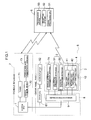
- FIG. 1 shows an example of a system configuration according to an embodiment of the present invention.
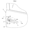
- FIG. 2 is an oblique view showing an example of a vehicle door according to an embodiment of the present invention.
- a smart-entry system configuration will be explained initially with reference to FIG. 1.
- This system recognizes when a person (driver) carrying a portable device 5, known as a remote control, approaches the vehicle or moves to the vehicle exterior. The system then automatically controls the locking and unlocking of a vehicle door 6. For example, when the person carrying the portable device 5 approaches the vehicle, the approaching will be recognized from the vehicle side.
- the system recognizes the intention of the person to unlock and automatically controls the unlocking of the vehicle door 6.
- the portable device 5 carried by the person has a reception system 52 composed of an antenna, tuner, or other device for receiving electromagnetic waves from the vehicle; a transmission system 53 composed of an antenna, modulation circuit, or other device for transmitting electromagnetic waves to the vehicle; and a signal processing CPU 51 for controlling sending and receiving, interpreting received signals, generating transmitted signals, and performing other types of signal processing.
- a reception system 52 composed of an antenna, tuner, or other device for receiving electromagnetic waves from the vehicle
- a transmission system 53 composed of an antenna, modulation circuit, or other device for transmitting electromagnetic waves to the vehicle
- a signal processing CPU 51 for controlling sending and receiving, interpreting received signals, generating transmitted signals, and performing other types of signal processing.
- the vehicle interior is provided with a system ECU (Electronic Control Unit) 1 acting as control means for executing overall control over the smart-entry system; a tuner 71 for receiving transmitted signals from the portable device 5; a vehicle interior transmission antenna 73 for transmitting signals to the portable device 5; and a vehicle interior driver 72 for modulating, amplifying, and performing other processes on the signals transmitted via the vehicle interior transmission antenna 73.
- the system ECU 1 also has recognition means for recognizing the communication device 5 approaching the vehicle or the movement of the communication device 5 to the vehicle exterior, by communication with the portable device 5 via the above communication means.
- the door panel part of the vehicle door 6 is equipped with a door handle 2 acting as an operating part for operating the opening and closing of the vehicle door 6.
- the door handle 2 is supported by a handle frame 8 provided to the interior of the door panel part of the vehicle door 6 (see FIG. 3).
- a vehicle exterior transmission antenna 74 for transmitting signals to the portable device 5 an operation detector 3 for detecting the operation of the door handle 2 by the person, and a light-emitting part 4 for indicating the locked or unlocked state of the vehicle door 6 are provided to the door handle 2 mounted on the vehicle door 6.
- a vehicle exterior driver 9 for transferring the signals of the components provided to the door handle 2 is provided to the interior of a handle frame 8 that supports the door handle 2 on the vehicle door 6.
- a door actuator 62 for operating the lock (key) mechanism of the vehicle door 6 and performing locking and unlocking, and a door ECU 61 for controlling the door actuator 62 are provided to the interior of the door panel part of the vehicle door 6.
- the door ECU 61 and the vehicle exterior driver 9 are controlled by the system ECU 1.
- the operation detector 3 provided to the door handle 2 has two members: an unlocking operation detector 31 for detecting the intention of the person to unlock, and a locking operation detector 32 for detecting the intention of the person to lock.
- the light-emitting part 4 has two parts, i.e., a first light-emitting part 41 and a second light-emitting part 42, so that light is emitted from the door handle 2 in different directions.
- the first light-emitting part 41 emits light into the space between the door handle 2 and the vehicle door 6, and the second light-emitting part 42 emits light to the exterior of the door handle 2.
- FIG. 3 is a cross-sectional view of the door handle part as seen from the direction III of FIG. 2.
- the door handle 2 is supported by the handle frame 8 across a door panel 60.
- a handle cap 21 is also supported by the handle frame 8.
- a key cylinder 22 used for manually locking and unlocking of the vehicle door 6 with a mechanical key operation is provided to the handle cap 21.
- the vehicle exterior driver 9 is provided within the handle frame 8 and connected to the parts within the door handle 2 and to the system ECU 1 in the vehicle interior by a wire harness 91.
- the vehicle exterior transmission antenna 74, the operation detector 3, and the light-emitting part 4 are provided to the interior of the door handle 2. As shown in FIG. 3, the vehicle exterior transmission antenna 74 is positioned in the central section of the door handle 2.
- the present embodiment is configured with a loop antenna employing ferrite, but it is also possible to use other configurations that correspond to the frequency band employed and can be positioned within the door handle.
- the locking operation detector 32 is provided to the side that does not face the door panel 60 (the vehicle door 6) of the door handle 2, i.e., the outer side.
- the unlocking operation detector 31 is provided to the side that faces the door panel 60 of the door handle 2, i.e., the inner side. When a person attempts to open the vehicle door 6, the door handle is pulled by a hand.
- the unlocking operation detector 31 is provided to the inner side of the door handle 2 so that hand contact on the door handle 2 will be detected at such times.
- the locking operation detector 32 is provided to the outer side of the door handle 2 so that the intention to lock will be recognized from the person pushing or touching the outer side of the door handle 2 with a finger or other body part after exiting the vehicle and closing the vehicle door 6.
- the first light-emitting part 41 is positioned on the inner side of the door handle 2 in the vicinity of the unlocking operation detector 31 as a component of the light-emitting part 4 in order to emit light into the space between the door handle 2 and the door panel 60 (the vehicle door 6).
- the second light-emitting part 42 which emits light outwardly, is positioned on the outer side of the door handle 2.
- the second light-emitting part 42 is disposed so as to surround the locking operation detector 32, as shown in FIG. 2, and is visible from the exterior of the door handle 2.
- the ornamental light part 40 is configured from a visible portion of the upper door handle 2.
- the ornamental light part 40 can be satisfactorily recognized from the exterior when the person touches the locking operation detector 32 with a finger, even if the finger covers a portion thereof.
- the configuration of the ornamental light part 40 may continue completely or partially around the circumference of the locking operation detector 32. As long as the arrangement allows the location of the locking operation detector 32 to be clearly displayed, the configuration need not be limited to the form shown in FIG. 2.
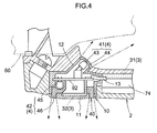
- FIG. 4 shows an example configuration of the operation detectors and the light-emitting parts according to an embodiment of the present invention.
- a human detection sensor based on the electrostatic capacitance principle is used as the locking operation detector 32.
- the first light-emitting part 41 has an LED (light-emitting diode) 43 and a diffusing member 44 composed of a diffusing resin, and is arranged so as to emit light into the space between the door handle 2 and the door panel 60.
- the second light-emitting part 42 has an LED 45 and a diffusing member 46 composed of a diffusing resin, and is arranged so as to emit light to the exterior of the vehicle.
- the diffusing member 46 of the second light-emitting part 42 is arranged so as to surround the periphery of the locking operation detector 32, as has already been explained, and constitutes the ornamental light part 40 visible from the exterior of the door handle 2.
- the LEDs and the diffusing members composed of diffusing resins are shown as being distinct, but the configuration is not limited thereto. Integrated LED modules or the like may be used.
- the LED 43 of the first light-emitting part 41 is mounted on one surface of a substrate 92, and the LED 45 of the second light-emitting part 42 is mounted on the other surface of the substrate 92.
- the human detection sensor of the locking operation detector 32 is also mounted on the substrate 92.
- the substrate 92 is mounted on a case 12 that is equipped with the diffusing member 44 for the LED 43.
- a cover part 11 equipped with the diffusing member 46 for the LED 45 covers and seals the case 12 in an airtight manner.
- a configuration may be employed wherein the locking operation detector 32 is arranged in advance on the reverse side of the cover part 11, and the locking operation detector 32 and substrate 92 are connected with a wire or other component.
- a cable 13 is provided to the substrate 92 via the case 12.
- the cable is designed to electrically connect the first light-emitting part 41, the second light-emitting part 42, the locking operation detector 32, and the vehicle exterior driver 9.
- This cable 13 is joined together with the wire harness 91.
- a configuration is provided whereby the section of the cable 13 that passes through the case 12 and the interface section between the case 12 and the cover part 11 are sealed, and the switch module 10 is hermetically sealed so as to be waterproof.
- the switch module 10 is thereby configured to be waterproof; therefore, the durability and reliability of the locking operation detector 32, the light-emitting part 4, and other components are increased.
- the components are preferably integrated into a single unit, which facilitates replacement tasks for maintenance purposes, and does not result in the operation detection functionality, light emission functionality, or ornamental light functionality being diminished as a result of replacement.
- the present embodiment has been described using a human detection sensor based on the electrostatic capacitance detection principle as the locking operation detector 32 that constitutes the switch module 10.
- the configuration is not limited thereto; e.g., a mechanical key switch (push switch) or other configuration may be employed.
- FIG. 5 is a block diagram showing an example of signal processing according to an embodiment of the present invention.
- a human detection sensor that uses electrostatic capacitance detection is used with the unlocking operation detector 31 and the locking operation detector 32.
- the vehicle exterior driver 9 has a sensor driver 93 for the human detection sensor that constitutes these operation detectors 3; a transmission amplifier 94 for transmitting wireless signals to the portable device 5; a first illumination driver 95 for controlling the light-emitting part 4; and a second illumination driver 96.
- Request signals are transmitted to the transmission amplifier 94 through the CLG terminal, modulated and amplified in the transmission amplifier 94, and then transmitted as electromagnetic waves from the vehicle exterior transmission antenna 74 within the door handle 2 to the vehicle exterior via the ANT1 terminal and the ANT2 terminal, all according to commands from the system ECU 1.
- the detection signal from the operation detector 3 is transmitted to the sensor driver 93 via the STG1 terminal and the STG2 terminal. If it is necessary for the system ECU 1 to recognize the intention of the person to unlock, the system ECU 1 controls the sensor driver 93 via the SEL terminal so that signals input via the terminal STG1 from the unlocking operation detector 31 are transmitted to the system ECU 1 via the sensor driver 93. If it is necessary for the system ECU 1 to recognize the intention of the person to lock, the system ECU 1 controls the sensor driver 93 via the SEL terminal so that signals input via the terminal STG2 from the locking operation detector 32 are transmitted to the system ECU 1 via the sensor driver 93. In this way, the selected operation detection signals are transmitted via the SENS terminal to the system ECU 1 by signals input from the SEL terminal.
- the system ECU 1 controls the light-emitting part 4 according to the locked or unlocked state of the vehicle door 6.
- the system ECU 1 controls the first illumination driver 95 and the second illumination driver 96, respectively, via the ILM1 terminal and the ILM3 terminal, causes a drive signal to be output by the light-emitting part 4, and causes light to be emitted by the first light-emitting part 41 and the second light-emitting part 42 via the ILM2 terminal and the ILM4 terminal.
- the first light-emitting part 41 and the second light-emitting part 42 have the LED 43 and LED 45.
- a resistance 47 and a resistance 48 provide resistance to limit the electrical current flowing into the LEDs.
- control of the light-emitting part 4" refers to control over illumination being enabled or disabled, and control or other action over continuous or intermittent (blinking) illumination. Additionally, when the LED 43 and the LED 45 are not monochrome LEDs but elements capable of emitting light in a plurality of colors, the selection of the color of emitted light may be controlled.
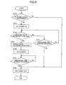
- FIG. 6 is a flow chart showing the unlocking operation according to an embodiment of the present invention.
- the system ECU 1 When the vehicle is in a parked and locked state, the system ECU 1 outputs a request signal to the vehicle exterior driver 9 positioned on the door panel 60 of the vehicle door 6 in order to recognize the portable device 5, which is an electronic key registered to the vehicle.
- the transmission amplifier 94 within the vehicle exterior driver 9 modulates and amplifies the request signal, and transmits electromagnetic waves to the vehicle exterior from the vehicle exterior transmission antenna 74 arranged on the door handle 2. If the portable device 5 approaches the vehicle at this point, the transmitted electromagnetic waves will be received by the reception system 52 of the portable device 5.
- the portable device 5 will then process the received signal in the signal processing CPU 51 and transmits the attributes, registration code, and other response information of the received signal via the transmission system 53.
- the attributes pertain to source-indicating information; e.g., that the received signal was transmitted via the vehicle exterior transmission antenna 74.
- electromagnetic waves transmitted from the portable device 5 are received by the tuner 71.
- the system ECU 1 verifies the attributes, registration code, and other response information, and recognizes that the portable device 5 serving as the electronic key registered for the vehicle has come close (step S100).
- the smart-entry system shifts to unlocking detection mode.
- the system ECU 1 energizes the first light-emitting part 41 to emit light.
- the LED 43 of the first light-emitting part 41 is turned on by the first illumination driver 95 of the vehicle exterior driver 9 (step S101).
- the system ECU 1 controls the sensor driver 93 of the vehicle exterior driver 9 via the SEL terminal, and monitors over a fixed time interval whether a detection signal is input from the unlocking operation detector 31 (step S102 and step S107). If a detection signal is not transmitted from the unlocking operation detector 31 to the system ECU 1 via the SENS terminal, even if the prescribed time interval is exceeded, the LED 43 is turned off (step S106) and the process ends.
- step S103 If a detection signal is input from the unlocking operation detector 31 within the prescribed time interval, the system ECU 1 issues an unlock control to the door ECU 61. The door actuator 62 is then driven and the vehicle door 6 is unlocked (step S103).
- the system ECU 1 causes the LED 43 to illuminate intermittently (blink) (step S104), informing the person that the vehicle door 6 is unlocked. After blinking over a prescribed time interval (step S105), the LED 43 is turned off (step S106), and the unlocking process performed by the smart-entry system ends.
- any blinking pattern can be used as long as the pattern can be recognized by the person.
- the state of the vehicle door 6 is indicated according to whether the LED 43 is continuously or intermittently illuminated. However, if the LED 43 is capable of changing the color of emitted light, the state of the vehicle door 6 may be expressed by controlling the changing of the color of emitted light. It shall be apparent that the indication operation of continuous illumination or blinking of the LED 43 may be reversed, and that indication may be performed via a combination of blinking or continuous illumination and changes in the color of emitted light.
- the vehicle door 6 can be satisfactorily unlocked when they place their hand on the door handle 2. It is additionally possible to indicate clearly that unlocking detection is in an enabled state (e.g., when the LED 43 is continuously illuminated) and that the door is unlocked (e.g., when the LED 43 is blinking). Therefore, the present system can offer exceptional convenience. Furthermore, when the surroundings are dark, such as at night, the person may have difficulty determining the location of the door handle 2. However, according to the present embodiment, the space between the opposing vehicle door 6 and door handle 2 is illuminated, allowing the person to place a hand on the door handle 2 without difficulty. As a result, the intention of the person to unlock can be satisfactorily detected by the unlocking operation detector 31 provided to the door handle 2, which increases the level of convenience provided to the person.
- FIG. 7 is a flow chart showing the locking operation according to an embodiment of the present invention.
- the locking operation occurring when the person exits the vehicle will be described with reference to FIG. 7.
- the portable device 5 (the electronic key) carried by the person is also in the vehicle interior.
- the portable device 5 receives a request signal that is modulated and amplified by the vehicle interior driver 72 positioned in the vehicle interior, and then transmitted from the vehicle interior transmission antenna 73 positioned in the vehicle interior.
- the portable device 5 processes the received signal in the signal processing CPU 51, and transmits the attributes, registration code, and other response information of the received signal via the transmission system 53.
- Electromagnetic waves transmitted from the portable device 5 are received by the tuner 71.
- the system ECU 1 verifies the response information and recognizes the presence of the portable device 5 within the vehicle.
- step S200 When the person carries the portable device 5, exits the vehicle, and closes the vehicle door 6 in this state, the aforedescribed communication is stopped, and the system ECU 1 recognizes that the portable device 5 has moved from the vehicle interior to the vehicle exterior (step S200). It is possible for verification to be performed in combination therewith in regard to the ability for communication to be established with the signals transmitted by the vehicle exterior transmission antenna 74, as described for the unlocking operation.
- the smart-entry system Upon verifying that the person has exited the vehicle and closed the vehicle door 6, the smart-entry system shifts to locking detection mode.
- the system ECU 1 energizes the second light-emitting part 42 to emit light.
- the LED 45 of the second light-emitting part 42 is caused to illuminate intermittently (blink) by the second illumination driver 96 of the vehicle exterior driver 9 (step S201).
- the LED 45 blinks, the blinking pattern will be visible from the exterior of the door handle 2 via the ornamental light part 40. Any blinking pattern may be used as long as the pattern can be recognized by the person.
- the system ECU 1 controls the sensor driver 93 of the vehicle exterior driver 9 via the SEL terminal and monitors over a prescribed time interval whether a detection signal is input from the locking operation detector 32 (step S202 and step S207). If a detection signal is not transmitted from the locking operation detector 32 to the system ECU 1 via the SENS terminal, even if the prescribed time interval is exceeded, the LED 45 will be turned off (step S206) and the process ends.
- the system ECU 1 issues a locking control command to the door ECU 61.
- the door actuator 62 is then driven and the vehicle door 6 is locked (step 5203).
- the system ECU 1 causes the LED 45 to be turned on (step S204), informing the person that the vehicle door has been locked.
- the LED 45 is turned off (step S206) and the locking process as performed by the smart-entry system ends.
- the ornamental light part 40 is illuminated in order to indicate the state of the vehicle door 6 according to blinking or continuous illumination, or, rather, according to the pattern of intermittent or continuous illumination, of the LED 45.
- the LED 45 is capable of changing the color of emitted light
- the state of the vehicle door 6 may be indicated by performing control to change the color of emitted light. It shall be apparent that the indication operation using continuous illumination or blinking of the LED 45 can be reversed, and indication may be performed via a combination of blinking, continuous illumination, and changes in the color of emitted light.
- the light-emitting part 42 may be configured to have an LED that can change between emitting two colors of light.
- the present system can offer exceptional convenience. Furthermore, when the surroundings are dark, such as at night, the person may have difficulty determining the location of the locking operation detector 32 provided to the outer side of the door handle 2.
- the ornamental light part 40 is provided to the periphery of the locking operation detector 32. Therefore, even if the locking operation detector 32 is operated with a finger, for example, the ornamental light part 40 will not be completely covered and the locking operation detector 32 may be operated satisfactorily. As a result, the intention of the person to unlock can be satisfactorily detected by the locking operation detector 32, which improves the level of convenience provided to the person.
- FIG. 8 shows a sample configuration of operation detectors and a light-emitting part according to a second embodiment of the present invention
- FIG. 9 shows a sample configuration of operation detectors and a light-emitting part according to a third embodiment of the present invention.
- FIGS. 8, 9 show configurations having only a light-emitting part 4 corresponding to the second light-emitting part 42 of the earlier embodiment.
- FIG. 8 is an example using the same electrostatically capacitive human detection sensor as in the earlier embodiment for the locking operation detector 32 that constitutes the switch module 10.
- the LED 45 of the light-emitting part 4 and the human detection sensor of the locking operation detector 32 are mounted on one surface of the substrate 92.
- the substrate 92 is mounted on the case 12, which is covered and hermetically sealed by the cover part 11 equipped with the diffusing member 46 for the LED 45 that functions as the ornamental light part 40.
- the locking operation detector 32 is positioned in advance on the reverse side of the cover part 11, and the locking operation detector 32 and the substrate 92 are connected using a wire or other component.
- a cable 13 is provided to the substrate 92 via the case 12 for electrically connecting the light-emitting part 4, the locking operation detector 32, and the vehicle exterior driver 9. This cable 13 is joined together with the wire harness 91.
- a configuration is provided whereby the section of the cable 13 that passes through the case 12 and the interface section between the case 12 and the cover part 11 are sealed, and the switch module 10 is hermetically sealed so as to be waterproof.
- FIG. 9 is an example showing a configuration wherein a mechanical key switch is used as the locking operation detector 32.
- the LED 45 of the light-emitting part 4 is mounted on one surface of the substrate 92.
- a switch 15 is mounted on a fixed case 12b.
- the substrate 92 is attached to the switch 15 so as to act as a cover.
- a through-hole is provided to the substrate 92 to accommodate a transmission member 16, which transmits operational force to the mechanical key of the switch 15.
- the transmission member 16 is provided to a sliding case 12a along with an operating part 11 that is operated by being pushed by a person, and with the diffusing member 46 that is composed of a diffusing resin and functions as the ornamental light part 40.
- the sliding case 12a covers the fixed case 12b with an O-ring 14 sandwiched therebetween, and constitutes the integrated switch module 10.
- the sliding case 12a is configured to slide in the direction of the fixed case 12b fixed to the door handle 2 when the person presses the switch module 10, so that the mechanical key of the switch 15 will be pushed.
- the O-ring 14 is held between the sliding case 12a and the fixed case 12b during this action, and maintains waterproofness.
- the cable 13 that electrically connects the light-emitting part 4, the locking operation detector 32, and the vehicle exterior driver 9 is provided through the fixed case 12b. As in the other sample configurations, the cable 13 is joined together with the wire harness 91.
- the section of the cable 13 that passes through the case 12b is sealed, and the switch module 10 is kept waterproof.
- the present invention can provide an apparatus for opening and closing a vehicle door that is exceptionally durable, and performs indications so that a person can reliably recognize the locked or unlocked state of a vehicle door.
- the present invention recognizes the intention of a person to lock or unlock a vehicle door, and can be used as an apparatus for opening and closing a vehicle door corresponding to a locking system (smart-entry system) that controls the locking and unlocking of the vehicle door.
- a locking system smart-entry system
Abstract
Description
- The present invention relates to an apparatus for opening and closing a vehicle door, comprising control means for recognizing the intention of a person to lock or unlock the vehicle door and controlling the locking and unlocking of the vehicle door.
- There are locking systems (smart-entry systems) that detect when a person approaches or exits a vehicle, recognize the intention of the person to lock or unlock the vehicle door, and automatically control the locking and unlocking of the vehicle door. However, these systems lack convenience in that if the person has not been informed as to whether a vehicle door controlled by such a smart-entry system is locked or unlocked, ultimately the person must verify each time whether the vehicle door is locked or unlocked.
-
Patent Document 1 discloses a technique for wirelessly locking and unlocking a vehicle door from outside the vehicle based on a method for indicating the state of the vehicle door in a so-called keyless entry. It is proposed in this patent document that, when the vehicle door is locked or unlocked, the quantity or type of emitted light by the interior illumination, headlights, taillights, or the like is determined in correspondence with the brightness of the surroundings of the vehicle, and a light control signal is outputted; or the volume or tone of a buzzer is determined in correspondence with the brightness of the surroundings of the vehicle, and a sound control signal is outputted. Specifically, when the surroundings are bright, such as during daytime, the state may not be readily recognized via emitted light alone; therefore, the emitted light is minimized and a sound is produced by a buzzer. When the surroundings are dark, such as in the evening or at night, the buzzer is minimized and light is emitted. -
Patent Document 2 discloses a system wherein the exterior part of a door handle grip part is composed of a light-permeable or transparent material, and the interior is provided with a light source. If applied to a smart-entry system, this configuration is able to indicate locking and unlocking in an easily visible location when a person enters or exits the vehicle. - Patent Document 1 :
Japanese Patent Application "kokai" No. 2000-45593 Pages 4 through 5, FIG. 2) - Patent Document 2 :
German Patent No. 10060780 Specification (FIG. 2) - However, according to the art described in
Patent Document 1, the interior illumination, headlights, taillights, and the like are positioned away from the handle that a person uses to open or close the vehicle door. Therefore, in the apparatus for opening and closing a vehicle door in a smart-entry system that automatically locks or unlocks when a person operates the door handle, the person cannot necessarily reliably recognize the state of the vehicle door. - With smart-entry systems, the person does not use a wireless key, and the intention to lock or unlock is recognized by the vehicle, whereupon locking or unlocking is then carried out. Therefore, this intention must be accurately transmitted to the vehicle. The intention is often transmitted based on an action of the person attempting to open or close the vehicle door, such as the action of placing a hand on the door handle. When the surroundings are dark, such as at night, people have difficulty in determining the location of the door handle to be operated and thus may not be able to accurately operate the door handle. In such circumstances, a smart-entry system does not smoothly lock and unlock the vehicle door, which should be performed automatically, and thus lacks convenience.
- When the vehicle door is locked using a smart-entry system after the person has exited the vehicle, the intention to lock is often recognized by a sensor, switch, or other device provided to the exterior of the door handle. This sensor, switch, or other device has an effect on the appearance of the vehicle, and is therefore often installed in a small area generally a little larger than a postage stamp on the exterior of the door handle. When parking at night in an unlit location, the person may fail to visually locate the sensor or switch, or cover the location of the sensor or switch with their own finger, perhaps making it impossible for an intention to lock to be satisfactorily recognized. No method has yet been proposed to satisfactorily indicate the target location that the person should operate in order to resolve these drawbacks.
- In the configuration described in
Patent Document 2, the door handle part may be a member that the person operates regularly, and thus a concern is raised in that the area composed of transparent or light-permeable material may be damaged or fouled, resulting in diminished light intensity. Furthermore, the door handle part has a large hollow space and is provided with an internal light source; therefore, the configuration must ensure strength and durability. In order to apply this configuration to a smart-entry system, a detector for detecting the intention of the person to lock or unlock must be provided on the handle. However, this detector is not shown in the configuration shown inPatent Document 2. Furthermore, providing a detector would necessitate an electrical connection, and as the door handle part is always exposed to the outside, a configuration for protecting the electrically connecting part from wind, rain, and other inclement conditions would also be necessary. - With the foregoing in view, it is an object of the present invention to provide an apparatus for opening and closing a vehicle door that is exceptionally durable and provides indication enabling a person to reliably recognize the locked or unlocked state of a vehicle door.
- In order to achieve the above object, the apparatus for opening and closing a vehicle door according to the present invention comprises control means for recognizing an intention of the person to lock or unlock the vehicle door and controlling the locking or unlocking of the vehicle door. The characterizing configuration of the apparatus is described hereunder.
Specifically, the apparatus is characterized in comprising
a door handle for opening and closing a vehicle door;
an operation detector provided to the door handle in order to detect a state of the door handle as operated by the person;
an ornamental light part that is provided so as to enclose the periphery of the operation detector and is visible from an exterior of the door handle during actuation of the operation sensor by the person; and
a light-emitting part for illuminating the ornamental light part; wherein
the light emitting part is energized by the control means according to a controlled state in which the vehicle door is locked or unlocked. - As an example, the operation detector provided to the exterior of the door handle has an effect on the appearance of the vehicle and is therefore often installed in a small area. For this reason, in unlit locations at night the person may fail to visually locate the operation detector, or may cover the location of the operation detector with their own finger, which can make it impossible for the intention of the person to be satisfactorily recognized. However, according to the above characterizing configuration, the light-emitting part is energized to emit light in accordance with the controlled state in which the vehicle door is locked or unlocked, and the ornamental light part, which is visible from the exterior of the door handle and encloses the periphery of the operation detector actuated by the person, is illuminated. Therefore, this configuration is preferable in that the location to be operated can be clearly indicated to the person even at night and will not be covered by a finger.
- The configuration above is further characterized in having a plurality of operation detectors, and the ornamental light part that is visible from the exterior of the door handle being provided to at least one of the operation detectors.
- According to the above characterizing configuration, different operation detectors are provided for locking and unlocking, and the ornamental light part visible from the exterior of the door handle can be provided to at least one of the detectors. For example, the operation detectors may be configured so that when the door is unlocked, the detectors will detect hand contact when the handle is gripped, and when the door is locked, the detectors will detect a push switch, touch sensor, or other device provided to the exterior of the door handle being operated when touched by a finger. It is thus possible to obtain a preferred configuration in which an operation detector that is operable by a finger and is positioned in a small area on the exterior of the door handle can provide a satisfactory indication.
- In this case, the light-emitting part and the operation detector equipped with the ornamental light part are preferably formed integrally, made waterproof, and housed inside the door handle. The door handle is always exposed on the exterior of the vehicle and is subjected to wind, rain, and other elements. However, the operation detectors, light-emitting part, and other parts housed inside the door handle have electrical connections, making it necessary to prevent water seepage. A configuration such as a switch module wherein the light-emitting part and the operation detector equipped with the ornamental light part are formed integrally and made waterproof is preferable in improving durability and reliability. Furthermore, having an integrated configuration means that maintenance-related replacement tasks are straightforward, and that replacement does not reduce operation detection functionality, light emission functionality, indication functionality of the ornamental light part, or other functionalities.
- In the configuration above, the control means is equipped with recognition means for recognizing a portable device by means of telecommunication therebetween, and configured such that the control means recognizes the intention of a person to unlock the vehicle door based on detected information of the operation detector when it has been recognized that the portable device is approaching the vehicle; and the intention of the person to lock the vehicle door is recognized based on detected information of the operation detector when it is recognized that the portable device is moving from the vehicle interior to the vehicle exterior.
- With this kind of configuration, the intention to lock or unlock can be recognized based on the recognized state of the portable device as the person carrying the portable device approaches the vehicle, moves from the vehicle interior to the vehicle exterior, or performs other similar actions. Therefore, the intention of the person can be more accurately recognized, and effective indication is possible.
- This configuration is further suitable in that the control means is configured so that the light emission of the light-emitting part is continuously energized in the case of one condition selected from a condition in which the portable device is recognized as approaching the vehicle, and a condition in which the vehicle door is unlocked; and the light emission of the light-emitting part is intermittently energized in the case of the other condition selected from the condition in which the portable device is recognized as approaching the vehicle and the condition in which the vehicle is unlocked.
- Light emission of the light-emitting part can thereby be energized continuously until the portable device approaches the vehicle, and the person operates the door handle, and light emission of the light-emitting part can be energized intermittently when the person operates and unlocks the door handle. Readiness to unlock is thereby indicated and the location to be operated for unlocking can be satisfactorily displayed until the door handle is operated by the person. Furthermore, when the door handle is operated and unlocked the completion of unlocking can be satisfactorily indicated.
- The control means is further configured to continuously energize the light emission of the light-emitting part upon one of either the movement of the portable device from the vehicle interior to the vehicle exterior being recognized, or the vehicle being locked; and to intermittently energize the light emission of the light-emitting part upon the other of either the movement of the portable device from the vehicle interior to the vehicle exterior being recognized, or the vehicle being locked.
- According to this configuration, locking is the same as above in that, e.g., when the portable device moves to the vehicle exterior, light emission of the light-emitting part is energized intermittently until the person operates the door handle, or light emission of the light-emitting part can be energized continuously until the person operates and locks the door handle. Readiness to lock is thereby indicated and the location to be operated for locking can be satisfactorily displayed until the door handle is operated by the person. Furthermore, when the door handle is operated and locked, the completion of locking can be satisfactorily indicated.
- The operation detectors in the various configurations above have sensor electrodes for sensing contact with the body of the person, and can be configured to detect an operation state of the door handle via these sensor electrodes. In an alternative configuration, a switch that can be operated by the person is provided and the operation state of the door handle is detected via the switch.
- It is preferable for a sensor electrode for sensing contact with a human body to be provided to the door handle and the operation state of the door handle to be detected via this sensor electrode, since it will be possible to detect the operation state of the door handle while the person naturally performs the action of operating the door handle in order to open the vehicle door. This arrangement is also preferred because after the person has exited the vehicle and closed the vehicle door, the switch provided on the door handle will again be operated, which will indicate the intention to lock the door, and instances of forgetting to lock the door will be eliminated. It shall be apparent that the person may operate the switch when unlocking, or the intention to lock may be transmitted via a sensor for sensing contact with the person when locking, and that locking and unlocking may be detected by the same method.
- In the configuration above, the light-emitting part may change the emitted light to a plurality of colors, and the control means preferably controls the color of emitted light.
- In this way, the light-emitting part is not limited to emitting a single color. When a plurality of colors can be emitted, the selection of the color of emitted light may be controlled by the control means. For example, if an LED (light-emitting diode) is used, a single element may change to emit two colors, red and green. Any light emission pattern for the light-emitting part is acceptable as long as the person can recognize the pattern. Therefore, the state of the vehicle door may be distinguished, e.g., not only by distinguishing between whether the light-emitting part is continuously or intermittently illuminated, but also by the color of emitted light. The person may mistakenly see only a portion of a blinking light pattern instead of a continuously illuminated light, or mistakenly see an extinguishing continuously illuminated light instead a blinking light, for example, but the frequency with which these kinds of mistakes are made can be reduced if the distinguishing is based on the color of emitted light.
- It is also preferable for the control means to control the light-emitting part so as to emit light in a plurality of patterns by combining the color of emitted light and a light illumination pattern according to which the light-emitting part is continuously or intermittently energized to emit light.
- For example, if the light-emitting part is configured to change between two colors, then combining the color of emitted light and the method of illumination (continuous or intermittent) will enable the light-emitting part to display at least four states (2 colors of emitted
light x 2 illumination methods = 4 states). It is accordingly possible to display, e.g., an unlockable state, completed unlocking, a lockable state, and completed locking. Thus, combining the illumination pattern with the color of emitted light allows the person to be informed of several states in a readily identifiable manner. - Embodiments for applying the present invention to a smart-entry system will be described below with reference to the accompanying drawings.
- FIG. 1 shows an example of a system configuration according to an embodiment of the present invention. FIG. 2 is an oblique view showing an example of a vehicle door according to an embodiment of the present invention. A smart-entry system configuration will be explained initially with reference to FIG. 1. This system recognizes when a person (driver) carrying a
portable device 5, known as a remote control, approaches the vehicle or moves to the vehicle exterior. The system then automatically controls the locking and unlocking of avehicle door 6. For example, when the person carrying theportable device 5 approaches the vehicle, the approaching will be recognized from the vehicle side. When the person places a hand on adoor handle 2 in order to attempt to open the vehicle door, the system recognizes the intention of the person to unlock and automatically controls the unlocking of thevehicle door 6. - As shown in FIG. 1, the
portable device 5 carried by the person has areception system 52 composed of an antenna, tuner, or other device for receiving electromagnetic waves from the vehicle; atransmission system 53 composed of an antenna, modulation circuit, or other device for transmitting electromagnetic waves to the vehicle; and asignal processing CPU 51 for controlling sending and receiving, interpreting received signals, generating transmitted signals, and performing other types of signal processing. - The vehicle interior is provided with a system ECU (Electronic Control Unit) 1 acting as control means for executing overall control over the smart-entry system; a
tuner 71 for receiving transmitted signals from theportable device 5; a vehicleinterior transmission antenna 73 for transmitting signals to theportable device 5; and a vehicleinterior driver 72 for modulating, amplifying, and performing other processes on the signals transmitted via the vehicleinterior transmission antenna 73. Thesystem ECU 1 also has recognition means for recognizing thecommunication device 5 approaching the vehicle or the movement of thecommunication device 5 to the vehicle exterior, by communication with theportable device 5 via the above communication means. - As shown in FIG. 2, the door panel part of the
vehicle door 6 is equipped with adoor handle 2 acting as an operating part for operating the opening and closing of thevehicle door 6. Thedoor handle 2 is supported by ahandle frame 8 provided to the interior of the door panel part of the vehicle door 6 (see FIG. 3). - As shown in FIG. 1, a vehicle
exterior transmission antenna 74 for transmitting signals to theportable device 5, anoperation detector 3 for detecting the operation of thedoor handle 2 by the person, and a light-emittingpart 4 for indicating the locked or unlocked state of thevehicle door 6 are provided to thedoor handle 2 mounted on thevehicle door 6. Furthermore, avehicle exterior driver 9 for transferring the signals of the components provided to thedoor handle 2 is provided to the interior of ahandle frame 8 that supports thedoor handle 2 on thevehicle door 6. Furthermore, adoor actuator 62 for operating the lock (key) mechanism of thevehicle door 6 and performing locking and unlocking, and adoor ECU 61 for controlling thedoor actuator 62 are provided to the interior of the door panel part of thevehicle door 6. Thedoor ECU 61 and thevehicle exterior driver 9 are controlled by thesystem ECU 1. - In the present embodiment, the
operation detector 3 provided to thedoor handle 2 has two members: an unlockingoperation detector 31 for detecting the intention of the person to unlock, and alocking operation detector 32 for detecting the intention of the person to lock. The light-emittingpart 4 has two parts, i.e., a first light-emittingpart 41 and a second light-emittingpart 42, so that light is emitted from thedoor handle 2 in different directions. For example, as shown in FIG. 2, the first light-emittingpart 41 emits light into the space between thedoor handle 2 and thevehicle door 6, and the second light-emittingpart 42 emits light to the exterior of thedoor handle 2. - FIG. 3 is a cross-sectional view of the door handle part as seen from the direction III of FIG. 2. As shown in FIG. 3, the
door handle 2 is supported by thehandle frame 8 across adoor panel 60. Ahandle cap 21 is also supported by thehandle frame 8. Akey cylinder 22 used for manually locking and unlocking of thevehicle door 6 with a mechanical key operation is provided to thehandle cap 21. Thevehicle exterior driver 9 is provided within thehandle frame 8 and connected to the parts within thedoor handle 2 and to thesystem ECU 1 in the vehicle interior by awire harness 91. - The vehicle
exterior transmission antenna 74, theoperation detector 3, and the light-emittingpart 4 are provided to the interior of thedoor handle 2. As shown in FIG. 3, the vehicleexterior transmission antenna 74 is positioned in the central section of thedoor handle 2. The present embodiment is configured with a loop antenna employing ferrite, but it is also possible to use other configurations that correspond to the frequency band employed and can be positioned within the door handle. - The locking
operation detector 32 is provided to the side that does not face the door panel 60 (the vehicle door 6) of thedoor handle 2, i.e., the outer side. The unlockingoperation detector 31 is provided to the side that faces thedoor panel 60 of thedoor handle 2, i.e., the inner side. When a person attempts to open thevehicle door 6, the door handle is pulled by a hand. The unlockingoperation detector 31 is provided to the inner side of thedoor handle 2 so that hand contact on thedoor handle 2 will be detected at such times. The lockingoperation detector 32 is provided to the outer side of thedoor handle 2 so that the intention to lock will be recognized from the person pushing or touching the outer side of thedoor handle 2 with a finger or other body part after exiting the vehicle and closing thevehicle door 6. - The first light-emitting
part 41 is positioned on the inner side of thedoor handle 2 in the vicinity of the unlockingoperation detector 31 as a component of the light-emittingpart 4 in order to emit light into the space between thedoor handle 2 and the door panel 60 (the vehicle door 6). The second light-emittingpart 42, which emits light outwardly, is positioned on the outer side of thedoor handle 2. The second light-emittingpart 42 is disposed so as to surround thelocking operation detector 32, as shown in FIG. 2, and is visible from the exterior of thedoor handle 2. The ornamentallight part 40 is configured from a visible portion of theupper door handle 2. In other words, being in a circumferential configuration, the ornamentallight part 40 can be satisfactorily recognized from the exterior when the person touches thelocking operation detector 32 with a finger, even if the finger covers a portion thereof. The configuration of the ornamentallight part 40 may continue completely or partially around the circumference of thelocking operation detector 32. As long as the arrangement allows the location of thelocking operation detector 32 to be clearly displayed, the configuration need not be limited to the form shown in FIG. 2. - In the present embodiment as shown in FIG. 3, the locking
operation detector 32, the first light-emittingpart 41, and the second light-emittingpart 42 are integrated and configured as aswitch module 10. FIG. 4 shows an example configuration of the operation detectors and the light-emitting parts according to an embodiment of the present invention. In the present example, a human detection sensor based on the electrostatic capacitance principle is used as the lockingoperation detector 32. The first light-emittingpart 41 has an LED (light-emitting diode) 43 and a diffusing member 44 composed of a diffusing resin, and is arranged so as to emit light into the space between thedoor handle 2 and thedoor panel 60. The second light-emittingpart 42 has anLED 45 and a diffusingmember 46 composed of a diffusing resin, and is arranged so as to emit light to the exterior of the vehicle. The diffusingmember 46 of the second light-emittingpart 42 is arranged so as to surround the periphery of thelocking operation detector 32, as has already been explained, and constitutes the ornamentallight part 40 visible from the exterior of thedoor handle 2. In the present example, the LEDs and the diffusing members composed of diffusing resins are shown as being distinct, but the configuration is not limited thereto. Integrated LED modules or the like may be used. - As shown in FIG. 4, the
LED 43 of the first light-emittingpart 41 is mounted on one surface of asubstrate 92, and theLED 45 of the second light-emittingpart 42 is mounted on the other surface of thesubstrate 92. The human detection sensor of thelocking operation detector 32 is also mounted on thesubstrate 92. Thesubstrate 92 is mounted on acase 12 that is equipped with the diffusing member 44 for theLED 43. Acover part 11 equipped with the diffusingmember 46 for theLED 45 covers and seals thecase 12 in an airtight manner. In this case, a configuration may be employed wherein thelocking operation detector 32 is arranged in advance on the reverse side of thecover part 11, and thelocking operation detector 32 andsubstrate 92 are connected with a wire or other component. Acable 13 is provided to thesubstrate 92 via thecase 12. The cable is designed to electrically connect the first light-emittingpart 41, the second light-emittingpart 42, the lockingoperation detector 32, and thevehicle exterior driver 9. Thiscable 13 is joined together with thewire harness 91. A configuration is provided whereby the section of thecable 13 that passes through thecase 12 and the interface section between thecase 12 and thecover part 11 are sealed, and theswitch module 10 is hermetically sealed so as to be waterproof. - The
switch module 10 is thereby configured to be waterproof; therefore, the durability and reliability of thelocking operation detector 32, the light-emittingpart 4, and other components are increased. The components are preferably integrated into a single unit, which facilitates replacement tasks for maintenance purposes, and does not result in the operation detection functionality, light emission functionality, or ornamental light functionality being diminished as a result of replacement. - The present embodiment has been described using a human detection sensor based on the electrostatic capacitance detection principle as the locking
operation detector 32 that constitutes theswitch module 10. However, the configuration is not limited thereto; e.g., a mechanical key switch (push switch) or other configuration may be employed. - Following is a description and summary of signal processing according to the above configuration, with reference made to FIG. 5. FIG. 5 is a block diagram showing an example of signal processing according to an embodiment of the present invention. In the present embodiment, a human detection sensor that uses electrostatic capacitance detection is used with the unlocking
operation detector 31 and thelocking operation detector 32. Thevehicle exterior driver 9 has asensor driver 93 for the human detection sensor that constitutes theseoperation detectors 3; atransmission amplifier 94 for transmitting wireless signals to theportable device 5; afirst illumination driver 95 for controlling the light-emittingpart 4; and asecond illumination driver 96. - Request signals are transmitted to the
transmission amplifier 94 through the CLG terminal, modulated and amplified in thetransmission amplifier 94, and then transmitted as electromagnetic waves from the vehicleexterior transmission antenna 74 within thedoor handle 2 to the vehicle exterior via the ANT1 terminal and the ANT2 terminal, all according to commands from thesystem ECU 1. - The detection signal from the
operation detector 3 is transmitted to thesensor driver 93 via the STG1 terminal and the STG2 terminal. If it is necessary for thesystem ECU 1 to recognize the intention of the person to unlock, thesystem ECU 1 controls thesensor driver 93 via the SEL terminal so that signals input via the terminal STG1 from the unlockingoperation detector 31 are transmitted to thesystem ECU 1 via thesensor driver 93. If it is necessary for thesystem ECU 1 to recognize the intention of the person to lock, thesystem ECU 1 controls thesensor driver 93 via the SEL terminal so that signals input via the terminal STG2 from the lockingoperation detector 32 are transmitted to thesystem ECU 1 via thesensor driver 93. In this way, the selected operation detection signals are transmitted via the SENS terminal to thesystem ECU 1 by signals input from the SEL terminal. - The
system ECU 1 controls the light-emittingpart 4 according to the locked or unlocked state of thevehicle door 6. Thesystem ECU 1 controls thefirst illumination driver 95 and thesecond illumination driver 96, respectively, via the ILM1 terminal and the ILM3 terminal, causes a drive signal to be output by the light-emittingpart 4, and causes light to be emitted by the first light-emittingpart 41 and the second light-emittingpart 42 via the ILM2 terminal and the ILM4 terminal. In the present embodiment, the first light-emittingpart 41 and the second light-emittingpart 42 have theLED 43 andLED 45. Aresistance 47 and aresistance 48 provide resistance to limit the electrical current flowing into the LEDs. As used herein, the term "control of the light-emittingpart 4" refers to control over illumination being enabled or disabled, and control or other action over continuous or intermittent (blinking) illumination. Additionally, when theLED 43 and theLED 45 are not monochrome LEDs but elements capable of emitting light in a plurality of colors, the selection of the color of emitted light may be controlled. - Following is a description of the operational flow for controlling locking and unlocking according to the above configuration. FIG. 6 is a flow chart showing the unlocking operation according to an embodiment of the present invention.
- When the vehicle is in a parked and locked state, the
system ECU 1 outputs a request signal to thevehicle exterior driver 9 positioned on thedoor panel 60 of thevehicle door 6 in order to recognize theportable device 5, which is an electronic key registered to the vehicle. Thetransmission amplifier 94 within thevehicle exterior driver 9 modulates and amplifies the request signal, and transmits electromagnetic waves to the vehicle exterior from the vehicleexterior transmission antenna 74 arranged on thedoor handle 2. If theportable device 5 approaches the vehicle at this point, the transmitted electromagnetic waves will be received by thereception system 52 of theportable device 5. Theportable device 5 will then process the received signal in thesignal processing CPU 51 and transmits the attributes, registration code, and other response information of the received signal via thetransmission system 53. In this case, the attributes pertain to source-indicating information; e.g., that the received signal was transmitted via the vehicleexterior transmission antenna 74. On the vehicle side, electromagnetic waves transmitted from theportable device 5 are received by thetuner 71. Thesystem ECU 1 verifies the attributes, registration code, and other response information, and recognizes that theportable device 5 serving as the electronic key registered for the vehicle has come close (step S100). - If the
portable device 5 is recognized, the smart-entry system shifts to unlocking detection mode. In order to inform the person that a shift to unlocking detection mode has been made, thesystem ECU 1 energizes the first light-emittingpart 41 to emit light. In other words, theLED 43 of the first light-emittingpart 41 is turned on by thefirst illumination driver 95 of the vehicle exterior driver 9 (step S101). Furthermore, thesystem ECU 1 controls thesensor driver 93 of thevehicle exterior driver 9 via the SEL terminal, and monitors over a fixed time interval whether a detection signal is input from the unlocking operation detector 31 (step S102 and step S107). If a detection signal is not transmitted from the unlockingoperation detector 31 to thesystem ECU 1 via the SENS terminal, even if the prescribed time interval is exceeded, theLED 43 is turned off (step S106) and the process ends. - If a detection signal is input from the unlocking
operation detector 31 within the prescribed time interval, thesystem ECU 1 issues an unlock control to thedoor ECU 61. Thedoor actuator 62 is then driven and thevehicle door 6 is unlocked (step S103). When thevehicle door 6 is unlocked, thesystem ECU 1 causes theLED 43 to illuminate intermittently (blink) (step S104), informing the person that thevehicle door 6 is unlocked. After blinking over a prescribed time interval (step S105), theLED 43 is turned off (step S106), and the unlocking process performed by the smart-entry system ends. - Any blinking pattern can be used as long as the pattern can be recognized by the person. Furthermore, in the present example, the state of the
vehicle door 6 is indicated according to whether theLED 43 is continuously or intermittently illuminated. However, if theLED 43 is capable of changing the color of emitted light, the state of thevehicle door 6 may be expressed by controlling the changing of the color of emitted light. It shall be apparent that the indication operation of continuous illumination or blinking of theLED 43 may be reversed, and that indication may be performed via a combination of blinking or continuous illumination and changes in the color of emitted light. - In this way, when the person carrying the
portable device 5 approaches the vehicle and attempts to open the door, thevehicle door 6 can be satisfactorily unlocked when they place their hand on thedoor handle 2. It is additionally possible to indicate clearly that unlocking detection is in an enabled state (e.g., when theLED 43 is continuously illuminated) and that the door is unlocked (e.g., when theLED 43 is blinking). Therefore, the present system can offer exceptional convenience. Furthermore, when the surroundings are dark, such as at night, the person may have difficulty determining the location of thedoor handle 2. However, according to the present embodiment, the space between the opposingvehicle door 6 anddoor handle 2 is illuminated, allowing the person to place a hand on thedoor handle 2 without difficulty. As a result, the intention of the person to unlock can be satisfactorily detected by the unlockingoperation detector 31 provided to thedoor handle 2, which increases the level of convenience provided to the person. - FIG. 7 is a flow chart showing the locking operation according to an embodiment of the present invention. The locking operation occurring when the person exits the vehicle will be described with reference to FIG. 7. When the person is in the vehicle interior, the portable device 5 (the electronic key) carried by the person is also in the vehicle interior. The
portable device 5 receives a request signal that is modulated and amplified by the vehicleinterior driver 72 positioned in the vehicle interior, and then transmitted from the vehicleinterior transmission antenna 73 positioned in the vehicle interior. Theportable device 5 processes the received signal in thesignal processing CPU 51, and transmits the attributes, registration code, and other response information of the received signal via thetransmission system 53. Electromagnetic waves transmitted from theportable device 5 are received by thetuner 71. Thesystem ECU 1 verifies the response information and recognizes the presence of theportable device 5 within the vehicle. - When the person carries the
portable device 5, exits the vehicle, and closes thevehicle door 6 in this state, the aforedescribed communication is stopped, and thesystem ECU 1 recognizes that theportable device 5 has moved from the vehicle interior to the vehicle exterior (step S200). It is possible for verification to be performed in combination therewith in regard to the ability for communication to be established with the signals transmitted by the vehicleexterior transmission antenna 74, as described for the unlocking operation. - Upon verifying that the person has exited the vehicle and closed the
vehicle door 6, the smart-entry system shifts to locking detection mode.
In order to inform the person that a shift to locking detection mode has been made, thesystem ECU 1 energizes the second light-emittingpart 42 to emit light. In other words, theLED 45 of the second light-emittingpart 42 is caused to illuminate intermittently (blink) by thesecond illumination driver 96 of the vehicle exterior driver 9 (step S201). When theLED 45 blinks, the blinking pattern will be visible from the exterior of thedoor handle 2 via the ornamentallight part 40. Any blinking pattern may be used as long as the pattern can be recognized by the person. Additionally, thesystem ECU 1 controls thesensor driver 93 of thevehicle exterior driver 9 via the SEL terminal and monitors over a prescribed time interval whether a detection signal is input from the locking operation detector 32 (step S202 and step S207). If a detection signal is not transmitted from the lockingoperation detector 32 to thesystem ECU 1 via the SENS terminal, even if the prescribed time interval is exceeded, theLED 45 will be turned off (step S206) and the process ends. - If a detection signal is input from the locking
operation detector 32 within the prescribed time interval, thesystem ECU 1 issues a locking control command to thedoor ECU 61. Thedoor actuator 62 is then driven and thevehicle door 6 is locked (step 5203). When thevehicle door 6 is locked, thesystem ECU 1 causes theLED 45 to be turned on (step S204), informing the person that the vehicle door has been locked. After being continuously illuminated over a prescribed time interval (step S205), theLED 45 is turned off (step S206) and the locking process as performed by the smart-entry system ends. - In the present example, the ornamental
light part 40 is illuminated in order to indicate the state of thevehicle door 6 according to blinking or continuous illumination, or, rather, according to the pattern of intermittent or continuous illumination, of theLED 45. However, if theLED 45 is capable of changing the color of emitted light, the state of thevehicle door 6 may be indicated by performing control to change the color of emitted light. It shall be apparent that the indication operation using continuous illumination or blinking of theLED 45 can be reversed, and indication may be performed via a combination of blinking, continuous illumination, and changes in the color of emitted light. - For example, the light-emitting
part 42 may be configured to have an LED that can change between emitting two colors of light. In this case, by combining the color of emitted light and the method of illumination (illumination pattern: continuous or intermittent), the ornamentallight part 40 can display at least four states (2 colors of emittedlight x 2 illumination methods = 4 states). In other words, it is possible to display four states: an unlockable state, completed unlocking, a lockable state, and completed locking. Control may also be simultaneously performed on the light-emittingpart 42 side during the unlocking operation described above as another possible embodiment, but a detailed description of the embodiment will be omitted. - It is thus possible to indicate clearly that locking detection is in an enabled state (e.g., when the
LED 45 is intermittently illuminated) and that the door is locked (e.g., when theLED 45 is turned on). Therefore, the present system can offer exceptional convenience. Furthermore, when the surroundings are dark, such as at night, the person may have difficulty determining the location of thelocking operation detector 32 provided to the outer side of thedoor handle 2. However, according to the present embodiment, the ornamentallight part 40 is provided to the periphery of thelocking operation detector 32. Therefore, even if thelocking operation detector 32 is operated with a finger, for example, the ornamentallight part 40 will not be completely covered and thelocking operation detector 32 may be operated satisfactorily. As a result, the intention of the person to unlock can be satisfactorily detected by the lockingoperation detector 32, which improves the level of convenience provided to the person. - An example configured such that light is emitted in different directions upon locking and unlocking was used in the description above, but it shall be apparent that the present invention may be used in a configuration wherein light is emitted in only one direction. FIG. 8 shows a sample configuration of operation detectors and a light-emitting part according to a second embodiment of the present invention, and FIG. 9 shows a sample configuration of operation detectors and a light-emitting part according to a third embodiment of the present invention. FIGS. 8, 9 show configurations having only a light-emitting
part 4 corresponding to the second light-emittingpart 42 of the earlier embodiment. FIG. 8 is an example using the same electrostatically capacitive human detection sensor as in the earlier embodiment for thelocking operation detector 32 that constitutes theswitch module 10. FIG. 9 is an example using a mechanical key switch or other type of push-button switch. The system configuration, signal processing, unlocking operation flow, locking operation flow, and other aspects should be made to accord with the embodiment explained above, and as such a detailed description of those aspects will be omitted. - Following is an explanation of the second embodiment. As shown in FIG. 8, the
LED 45 of the light-emittingpart 4 and the human detection sensor of thelocking operation detector 32 are mounted on one surface of thesubstrate 92. Thesubstrate 92 is mounted on thecase 12, which is covered and hermetically sealed by thecover part 11 equipped with the diffusingmember 46 for theLED 45 that functions as the ornamentallight part 40. In this case, it is possible to provide a configuration wherein thelocking operation detector 32 is positioned in advance on the reverse side of thecover part 11, and thelocking operation detector 32 and thesubstrate 92 are connected using a wire or other component. Acable 13 is provided to thesubstrate 92 via thecase 12 for electrically connecting the light-emittingpart 4, the lockingoperation detector 32, and thevehicle exterior driver 9. Thiscable 13 is joined together with thewire harness 91. A configuration is provided whereby the section of thecable 13 that passes through thecase 12 and the interface section between thecase 12 and thecover part 11 are sealed, and theswitch module 10 is hermetically sealed so as to be waterproof. - Following is a description of the third embodiment. FIG. 9 is an example showing a configuration wherein a mechanical key switch is used as the locking
operation detector 32. As shown in the drawing, theLED 45 of the light-emittingpart 4 is mounted on one surface of thesubstrate 92. Aswitch 15 is mounted on a fixedcase 12b. Thesubstrate 92 is attached to theswitch 15 so as to act as a cover. A through-hole is provided to thesubstrate 92 to accommodate atransmission member 16, which transmits operational force to the mechanical key of theswitch 15. Thetransmission member 16 is provided to a slidingcase 12a along with an operatingpart 11 that is operated by being pushed by a person, and with the diffusingmember 46 that is composed of a diffusing resin and functions as the ornamentallight part 40. The slidingcase 12a covers the fixedcase 12b with an O-ring 14 sandwiched therebetween, and constitutes theintegrated switch module 10. The slidingcase 12a is configured to slide in the direction of the fixedcase 12b fixed to thedoor handle 2 when the person presses theswitch module 10, so that the mechanical key of theswitch 15 will be pushed. The O-ring 14 is held between the slidingcase 12a and the fixedcase 12b during this action, and maintains waterproofness. Furthermore, thecable 13 that electrically connects the light-emittingpart 4, the lockingoperation detector 32, and thevehicle exterior driver 9 is provided through the fixedcase 12b. As in the other sample configurations, thecable 13 is joined together with thewire harness 91. The section of thecable 13 that passes through thecase 12b is sealed, and theswitch module 10 is kept waterproof. - As described above, the present invention can provide an apparatus for opening and closing a vehicle door that is exceptionally durable, and performs indications so that a person can reliably recognize the locked or unlocked state of a vehicle door.
- The present invention recognizes the intention of a person to lock or unlock a vehicle door, and can be used as an apparatus for opening and closing a vehicle door corresponding to a locking system (smart-entry system) that controls the locking and unlocking of the vehicle door.
-
- FIG. 1 shows an example of a system configuration according to an embodiment of the present invention;
- FIG. 2 is an oblique view showing an example of a vehicle door according to an embodiment of the present invention;
- FIG. 3 is a cross-sectional view of a door handle part as seen from direction III in FIG. 2;
- FIG. 4 shows a sample configuration of operation detectors and a light-emitting part according to an embodiment of the present invention;
- FIG. 5 is a block diagram showing an example of signal processing according to an embodiment of the present invention;
- FIG. 6 is a flow chart showing an unlocking operation according to an embodiment of the present invention;
- FIG. 7 is a flow chart showing a locking operation according to an embodiment of the present invention;
- FIG. 8 shows a sample configuration of operation detectors and light-emitting part according to a second embodiment of the present invention; and
- FIG. 9 shows a sample configuration of operation detectors and a light-emitting part according to a third embodiment of the present invention.
-
- 2
- DOOR HANDLE
- 3
- OPERATION DETECTOR
- 4
- LIGHT-EMITTING PART
- 6
- VEHICLE DOOR
- 40
- ORNAMENTAL LIGHT PART
Claims (9)
- An apparatus for opening and closing a vehicle door, comprising control means for recognizing an intention of a person to lock or unlock the vehicle door and controlling the locking or unlocking of the vehicle door, said apparatus for opening and closing a vehicle door further comprising:a door handle for performing an opening and closing operation of the vehicle door;an operation detector provided to the door handle in order to detect a state of the door handle as operated by the person;an ornamental light part that is provided so as to enclose a periphery of the operation detector and is visible from an exterior of the door handle during actuation of the operation detector by the person; anda light-emitting part for illuminating the ornamental light part; whereinthe light-emitting part is energized by the control means according to a controlled state in which the vehicle door is locked or unlocked.
- The apparatus for opening and closing a vehicle door according to claim 1, having:a plurality of operation detectors; andthe ornamental light part that is visible from the exterior of the door handle being provided to at least one of the operation detectors.
- The apparatus for opening and closing a vehicle door according to claim 1, wherein
the control means comprises recognition means for recognizing via telecommunication a portable device carried by the person;
the control means recognizes the intention of the person to unlock the vehicle door based on detected information of the operation detector when the portable device has been recognized to have come closer to the vehicle; and
the intention of the person to lock the vehicle door is recognized based on detected information of the operation detector when the portable device has been recognized to have moved from the vehicle interior to the vehicle exterior. - The apparatus for opening and closing a vehicle door according to claim 3, wherein
the control means continuously energizes the light-emitting part to emit light in the case of one condition selected from a condition in which the portable device is recognized as approaching the vehicle, and a condition in which the vehicle door is unlocked; and
intermittently energizes the light-emitting part to emit light in the case of the other condition selected from the condition in which the portable device is recognized as approaching the vehicle and the condition in which the vehicle is unlocked. - The apparatus for opening and closing a vehicle door according to claim 3, wherein
the control means continually energizes the light-emitting part to emit light in the case of one condition selected from a condition in which the portable device is recognized as moving from the vehicle interior to the vehicle exterior, and a condition in which the vehicle door is locked; and
intermittently energizes the light-emitting part to emit light in the case of the other condition selected from the condition in which the portable device is recognized as moving from the vehicle interior to the vehicle exterior, and the condition in which the vehicle door is locked. - The apparatus for opening and closing a vehicle door according to claim 1, wherein
the operation detector has a sensor electrode for detecting contact with the body of the person, and detects an operation state of the door handle via the sensor electrode. - The apparatus for opening and closing a vehicle door according to claim 1, wherein
the operation detector has a switch that can be operated by the person, and detects an operation state of the door handle via the switch. - The apparatus for opening and closing a vehicle door according to claim 1, wherein
the light-emitting part may change the color of emitted light to a plurality of colors; and
the control means controls the color of emitted light. - The apparatus for opening and closing a vehicle door according to claim 8, wherein
the control means performs control to cause the light-emitting part to emit light in a plurality of light emission patterns by combining the color of emitted light and a light illumination pattern according to which the light-emitting part is continuously or intermittently energized to emit light.
Applications Claiming Priority (2)
| Application Number | Priority Date | Filing Date | Title |
|---|---|---|---|
| JP2004184143A JP4240307B2 (en) | 2004-06-22 | 2004-06-22 | Vehicle door opening and closing device |
| PCT/JP2005/011314 WO2005124066A1 (en) | 2004-06-22 | 2005-06-21 | Opening and closing apparatus for vehicle door |
Publications (3)
| Publication Number | Publication Date |
|---|---|
| EP1760227A1 true EP1760227A1 (en) | 2007-03-07 |
| EP1760227A4 EP1760227A4 (en) | 2014-06-25 |
| EP1760227B1 EP1760227B1 (en) | 2016-03-16 |
Family
ID=35509722
Family Applications (1)
| Application Number | Title | Priority Date | Filing Date |
|---|---|---|---|
| EP05752983.6A Expired - Fee Related EP1760227B1 (en) | 2004-06-22 | 2005-06-21 | Opening and closing apparatus for vehicle door |
Country Status (5)
| Country | Link |
|---|---|
| US (1) | US7819442B2 (en) |
| EP (1) | EP1760227B1 (en) |
| JP (1) | JP4240307B2 (en) |
| CN (1) | CN1969104B (en) |
| WO (1) | WO2005124066A1 (en) |
Cited By (13)
| Publication number | Priority date | Publication date | Assignee | Title |
|---|---|---|---|---|
| US7333021B2 (en) | 2004-06-24 | 2008-02-19 | Aisin Seiki Kabushiki Kaisha | Opening/closing apparatus for vehicle door |
| EP1935717A3 (en) * | 2006-12-20 | 2009-12-30 | Huf Hülsbeck & Fürst GmbH & Co. KG | Actuating device for opening and closing a moveable component |
| WO2011061281A3 (en) * | 2009-11-20 | 2011-07-14 | Valeo Spa | Vehicle unlocking control device provided with an outer control member having an over-molded mounting |
| FR2993221A1 (en) * | 2012-07-13 | 2014-01-17 | Continental Automotive France | DEVICE AND METHOD FOR COMMUNICATION BETWEEN AN ELECTRONIC MODULE AND A DETECTION SENSOR COMPRISING A LIGHT SOURCE |
| FR2993222A1 (en) * | 2012-07-13 | 2014-01-17 | Continental Automotive France | DEVICE AND METHOD FOR COMMUNICATION BETWEEN AN ELECTRONIC MODULE AND A DETECTION SENSOR IN THE PRESENCE OF A LIGHT SOURCE |
| DE102012022877A1 (en) * | 2012-11-22 | 2014-03-06 | Audi Ag | Method for locking and unlocking a lock device for door of motor car, involves locking the lock device automatically at certain time period, after opening and subsequent closing of door |
| FR3015004A1 (en) * | 2013-12-18 | 2015-06-19 | Filec | ELECTRONIC DEVICE HOUSING TO BE PLACED INTO A MOTOR VEHICLE DOOR HANDLE, CORRESPONDING ELECTRONIC DEVICE AND CORRESPONDING DOOR HANDLE |
| WO2015148788A1 (en) * | 2014-03-26 | 2015-10-01 | Adac Plastics, Inc. | Handle assembly for a motor vehicle door |
| WO2015150157A1 (en) * | 2014-03-31 | 2015-10-08 | Huf Hülsbeck & Fürst Gmbh & Co. Kg | Electronic module with lighting means for a handle |
| FR3025824A1 (en) * | 2014-09-11 | 2016-03-18 | Continental Automotive France | METHOD FOR DETECTING ACTUATION OF A DOOR HANDLE OF A MOTOR VEHICLE |
| EP2632766A4 (en) * | 2010-10-28 | 2018-04-25 | Aisin Technical Center Of America, Inc. | Lit door handle for a vehicle |
| EP3194691A4 (en) * | 2014-09-17 | 2018-05-16 | Rollock OY | Indicating location of a lock |
| WO2019113056A1 (en) | 2017-12-05 | 2019-06-13 | Adac Plastics, Inc. | Door handle assembly for a motor vehicle |
Families Citing this family (78)
| Publication number | Priority date | Publication date | Assignee | Title |
|---|---|---|---|---|
| EP1795860B1 (en) * | 2004-09-28 | 2012-11-14 | Aisin Seiki Kabushiki Kaisha | Antenna assembly and door handle unit |
| JP4654945B2 (en) * | 2006-03-06 | 2011-03-23 | 豊田合成株式会社 | Door handle lighting system |
| DE102006013027B4 (en) * | 2006-03-20 | 2008-03-20 | SCHÜCO International KG | handle element |
| JP4934074B2 (en) * | 2007-03-07 | 2012-05-16 | 株式会社アルファ | Switch fixing structure |
| JP5078407B2 (en) * | 2007-03-29 | 2012-11-21 | 株式会社ホンダロック | VEHICLE OUT HANDLE DEVICE AND METHOD FOR MANUFACTURING VEHICLE OUT HANDLE DEVICE |
| JP4540004B2 (en) * | 2007-04-16 | 2010-09-08 | 庄吾 土田 | Blinker lamps that can change color |
| WO2008137634A1 (en) | 2007-05-03 | 2008-11-13 | Donnelly Corporation | Illumination module for a vehicle |
| JP4938580B2 (en) * | 2007-07-27 | 2012-05-23 | アイシン精機株式会社 | Door handle device |
| JP4751860B2 (en) * | 2007-07-27 | 2011-08-17 | アイシン精機株式会社 | Door handle device |
| JP4751861B2 (en) * | 2007-07-27 | 2011-08-17 | アイシン精機株式会社 | Door handle device |
| JP4990726B2 (en) * | 2007-09-06 | 2012-08-01 | サカエ理研工業株式会社 | Vehicle door handle device |
| JP4914816B2 (en) * | 2007-11-30 | 2012-04-11 | 株式会社アルファ | Automotive handle device |
| KR100896909B1 (en) * | 2007-12-14 | 2009-05-12 | 현대자동차주식회사 | Slide door control unit |
| DE102008010396B4 (en) * | 2008-02-21 | 2019-06-13 | GM Global Technology Operations LLC (n. d. Ges. d. Staates Delaware) | Status display Flexdoor, method for operating a status display, locking system with a status display and motor vehicle door with a status display |
| JP5324816B2 (en) * | 2008-05-08 | 2013-10-23 | アイシン精機株式会社 | Vehicle door handle |
| KR100974550B1 (en) * | 2008-07-15 | 2010-08-11 | 현대자동차주식회사 | A vehicle door locking apparatus control system |
| JP5086219B2 (en) * | 2008-09-30 | 2012-11-28 | 本田技研工業株式会社 | Trunk locking device for vehicle |
| JP5293087B2 (en) * | 2008-10-29 | 2013-09-18 | アイシン精機株式会社 | Vehicle door opening / closing operation device |
| KR20100053864A (en) * | 2008-11-13 | 2010-05-24 | 현대자동차주식회사 | Handle structure of door outside |
| JP2010216176A (en) * | 2009-03-18 | 2010-09-30 | Aisin Seiki Co Ltd | Door handle device for vehicle |
| JP5270421B2 (en) | 2009-03-30 | 2013-08-21 | 株式会社アルファ | Vehicle door handle device |
| JP5022483B2 (en) * | 2010-07-26 | 2012-09-12 | アイシン精機株式会社 | Vehicle door handle device |
| FR2964517B1 (en) * | 2010-09-06 | 2012-09-21 | Continental Automotive France | METHOD FOR DETERMINING PARASITE CONTACTS ON A DOOR HANDLE CONTACT DETECTION SENSOR OF A MOTOR VEHICLE |
| FR2965288B1 (en) * | 2010-09-28 | 2012-10-12 | Sicma Aero Seat | PALLET WITH DOUBLE LOCKING AND TRIPLE DETECTIONS |
| KR101230896B1 (en) * | 2010-11-23 | 2013-02-07 | 현대자동차주식회사 | Illuminator of the door outside handle for vehicle |
| JP5556620B2 (en) * | 2010-11-26 | 2014-07-23 | アイシン精機株式会社 | Door handle device |
| JP5513442B2 (en) * | 2011-05-27 | 2014-06-04 | 株式会社ホンダロック | Outdoor handle device for vehicle door |
| US9103143B2 (en) | 2011-09-26 | 2015-08-11 | Tesla Motors, Inc. | Door handle apparatus for vehicles |
| US9080352B2 (en) * | 2011-09-26 | 2015-07-14 | Tesla Motors, Inc. | Controller apparatus and sensors for a vehicle door handle |
| US8801245B2 (en) | 2011-11-14 | 2014-08-12 | Magna Mirrors Of America, Inc. | Illumination module for vehicle |
| DE102012100428A1 (en) * | 2012-01-19 | 2013-07-25 | Hella Kgaa Hueck & Co. | Door handle for motor car, has printed circuit board, antenna, and sensor activated when motor car is locked, and another sensor activated when motor car is unlocked, fastened outside at shell, and electrically directly connected with board |
| DE102012105117A1 (en) * | 2012-06-13 | 2013-12-19 | Huf Hülsbeck & Fürst Gmbh & Co. Kg | Approach detecting device |
| US9957737B2 (en) * | 2012-06-29 | 2018-05-01 | Ford Global Technologies, Llc | Flush-mounted door handle for vehicles |
| JP5974693B2 (en) * | 2012-07-10 | 2016-08-23 | アイシン精機株式会社 | Antenna drive device |
| TW201425096A (en) * | 2012-12-19 | 2014-07-01 | jian-liang Xie | Light warning method for vehicle door handle and light warning system thereof |
| US9227558B2 (en) * | 2013-01-14 | 2016-01-05 | GM Global Technology Operations LLC | Vehicle exterior door handle lighting |
| JP5940993B2 (en) * | 2013-02-07 | 2016-06-29 | 株式会社東海理化電機製作所 | Electronic key system |
| JP6148026B2 (en) * | 2013-02-07 | 2017-06-14 | 株式会社東海理化電機製作所 | Electronic key system |
| JP6148027B2 (en) * | 2013-02-07 | 2017-06-14 | 株式会社東海理化電機製作所 | Electronic key system |
| US9593514B2 (en) * | 2013-02-18 | 2017-03-14 | Ford Global Technologies, Llc | Seamless exterior handle for a vehicle door |
| JP6020251B2 (en) * | 2013-02-26 | 2016-11-02 | アイシン精機株式会社 | Operation input confirmation device and vehicle door handle device |
| US9080348B2 (en) * | 2013-04-19 | 2015-07-14 | GM Global Technology Operations LLC | Systems and methods for lock notification |
| DE102013105792A1 (en) * | 2013-06-05 | 2014-12-11 | Huf Hülsbeck & Fürst Gmbh & Co. Kg | Approach detecting device |
| JP6064806B2 (en) * | 2013-06-21 | 2017-01-25 | アイシン精機株式会社 | Vehicle door handle |
| FR3007876B1 (en) * | 2013-06-28 | 2016-09-16 | Continental Automotive France | METHOD FOR PROCESSING PRESENCE SIGNAL IN A FREE HAND ACCESS SYSTEM OF A CAPACITIVE SENSOR VEHICLE |
| JP5958939B2 (en) * | 2013-07-25 | 2016-08-02 | 株式会社ホンダロック | Vehicle door handle device |
| TWI464318B (en) * | 2013-07-29 | 2014-12-11 | Univ Nat Taipei Technology | Sensing device installed in a handle and vehicle door handle |
| JP2015085900A (en) * | 2013-11-01 | 2015-05-07 | トヨタ自動車九州株式会社 | Door knob light emitting device of automobile |
| JP5955302B2 (en) | 2013-11-19 | 2016-07-20 | 株式会社小糸製作所 | Door handle |
| JP5950468B2 (en) | 2013-11-19 | 2016-07-13 | 株式会社小糸製作所 | Door handle |
| JP5955303B2 (en) | 2013-11-19 | 2016-07-20 | 株式会社小糸製作所 | Door handle |
| CN105745121B (en) | 2013-11-19 | 2019-05-03 | 株式会社小糸制作所 | Lamps apparatus for vehicle |
| JP6195505B2 (en) | 2013-11-19 | 2017-09-13 | 株式会社小糸製作所 | Door handle |
| JP6576830B2 (en) | 2013-11-19 | 2019-09-18 | 株式会社小糸製作所 | Vehicle lamp |
| DE102014003505A1 (en) * | 2014-03-14 | 2015-09-17 | Kiekert Aktiengesellschaft | Motor vehicle door lock with child safety lock |
| JP2015229414A (en) * | 2014-06-05 | 2015-12-21 | アイシン精機株式会社 | Vehicle opening/closing body lighting device |
| CN106696894B (en) * | 2014-07-28 | 2018-12-21 | 保汇通(厦门)网络科技有限公司 | A kind of automotive keyless entering system based on smart phone |
| CN104442702B (en) * | 2014-07-28 | 2020-07-28 | 冯林 | Keyless entry system for automobile |
| EP3020895B1 (en) * | 2014-11-13 | 2017-11-15 | Huf Hülsbeck & Fürst GmbH & Co. KG | Handle for a vehicle with a pulling device |
| US20160138301A1 (en) * | 2014-11-14 | 2016-05-19 | The Boeing Company | Self-contained electronic stowage bin system |
| US9487140B2 (en) * | 2015-01-29 | 2016-11-08 | Ford Global Technologies, Llc | Closure lock status display system and related method |
| CN104796829B (en) * | 2015-03-30 | 2017-10-27 | 张家港市玉同电子科技有限公司 | Bimorph piezo electric potsherd and its application |
| US20170028795A1 (en) * | 2015-07-28 | 2017-02-02 | GM Global Technology Operations LLC | Indication of vehicle status using light |
| US10065556B2 (en) * | 2015-12-02 | 2018-09-04 | Ford Global Technologies Llc | Illuminated door-open warning for center-opening door |
| JP6392800B2 (en) * | 2016-02-26 | 2018-09-19 | 株式会社小糸製作所 | Door handle |
| JP6765070B2 (en) * | 2016-06-01 | 2020-10-07 | パナソニックIpマネジメント株式会社 | Electric lock system and electric lock device |
| DE102016110345A1 (en) * | 2016-06-03 | 2017-12-07 | Huf Hülsbeck & Fürst Gmbh & Co. Kg | Additional door handle module for a door handle unit |
| JP6853051B2 (en) * | 2017-01-24 | 2021-03-31 | 株式会社アルファ | Handle device |
| CN114135842A (en) * | 2017-03-16 | 2022-03-04 | 提爱思科技股份有限公司 | Lighting device |
| KR102390652B1 (en) * | 2017-05-18 | 2022-04-26 | 현대자동차주식회사 | Charging apparatus for vehicle |
| JP6674484B2 (en) * | 2018-01-18 | 2020-04-01 | 矢崎総業株式会社 | Lighting device for assist grip |
| US20190234121A1 (en) * | 2018-01-26 | 2019-08-01 | Novares Us Llc | Flush door handle assembly |
| JP6915559B2 (en) * | 2018-02-07 | 2021-08-04 | オムロン株式会社 | Door switch |
| EP3627457A1 (en) * | 2018-09-24 | 2020-03-25 | Hoppe Ag | Access system |
| JP7335577B2 (en) | 2018-11-19 | 2023-08-30 | 東京パーツ工業株式会社 | lighting equipment |
| CN113212129A (en) * | 2021-06-07 | 2021-08-06 | 中国第一汽车股份有限公司 | Vehicle door control method and device, vehicle and storage medium |
| CN114150967B (en) * | 2021-12-02 | 2022-11-25 | 深圳市兴嘉林电子科技有限公司 | Vehicle door control method and device and electronic equipment |
| KR20230156609A (en) * | 2022-05-06 | 2023-11-14 | 비플랫 유한회사 | Authentication System Using Light Emitting Unit of Transport Means and Authentication Information Processing Method by It |
Citations (9)
| Publication number | Priority date | Publication date | Assignee | Title |
|---|---|---|---|---|
| JPS62137972U (en) * | 1986-02-25 | 1987-08-31 | ||
| DE19843594A1 (en) * | 1998-09-23 | 2000-04-06 | Valeo Gmbh & Co Schliessyst Kg | Door handle for vehicle door which includes bearing bracket fixable at door and handle part swivelable at bracket with extension projecting inside of door |
| DE20020952U1 (en) * | 2000-10-19 | 2001-04-19 | Benkhardt Axel | Handle-type operating device for doors |
| DE10060780A1 (en) * | 2000-12-07 | 2002-06-13 | Bayerische Motoren Werke Ag | Door handle for use on road vehicle incorporates steady or blinking lamp underneath transparent layer on outside of handle |
| EP1253269A1 (en) * | 2001-04-28 | 2002-10-30 | Huf Hülsbeck & Fürst GmbH & Co. KG | Exterior control for vehicle locks of doors, flaps, or similar |
| US20030031025A1 (en) * | 2001-06-30 | 2003-02-13 | Huizenga David J. | Vehicle handle assembly |
| DE20317635U1 (en) * | 2003-11-14 | 2004-03-11 | Cherry Gmbh | Switch and lighting module for motor vehicles has a printed circuit board, strip conductors, transparent covers for light to pass through lighting elements and a rocker button |
| JP2004146260A (en) * | 2002-10-25 | 2004-05-20 | Yazaki Corp | Lightening type switch structure |
| EP1609674A1 (en) * | 2004-06-24 | 2005-12-28 | Aisin Seiki Kabushiki Kaisha | Opening/closing apparatus for vehicle door |
Family Cites Families (32)
| Publication number | Priority date | Publication date | Assignee | Title |
|---|---|---|---|---|
| US2273570A (en) * | 1940-09-11 | 1942-02-17 | Edward E Greenlees | Illuminating attachment for vehicle door locks |
| DE3136889C2 (en) | 1981-09-17 | 1985-09-26 | Daimler-Benz Ag, 7000 Stuttgart | Lighting device for operating elements such as switches or locks, in particular for motor vehicle locks |
| JPH01112261U (en) | 1988-01-21 | 1989-07-28 | ||
| JPH0633742Y2 (en) | 1988-03-08 | 1994-08-31 | 三菱自動車工業株式会社 | Vehicle remote control device |
| JPH01275239A (en) | 1988-04-28 | 1989-11-02 | Mazda Motor Corp | Door lock control device for vehicle |
| JPH0741643Y2 (en) | 1988-08-30 | 1995-09-27 | 株式会社アルファ | Electromagnetic wave detection display device for automobile |
| JPH0640297Y2 (en) | 1989-01-11 | 1994-10-19 | イオインダストリー株式会社 | Car door handle device |
| JP2760089B2 (en) | 1989-10-09 | 1998-05-28 | 日産自動車株式会社 | Door handle device |
| US5297010A (en) * | 1992-08-28 | 1994-03-22 | Itc Incorporated | Illuminated grab handle |
| JP3193587B2 (en) | 1995-05-26 | 2001-07-30 | 関東自動車工業株式会社 | Lighting device for automobile door handle |
| US6164805A (en) | 1998-04-20 | 2000-12-26 | Federal-Mogul World Wide, Inc. | Illuminated door handle for a vehicle |
| DE19757085A1 (en) | 1997-12-20 | 1999-06-24 | Hella Kg Hueck & Co | Device for illuminating an apron of a vehicle part |
| US6070998A (en) | 1998-01-23 | 2000-06-06 | General Motors Corporation | Fiber optic lighting system for vehicle door handle |
| DE19809716A1 (en) | 1998-03-06 | 1999-09-09 | Hella Kg Hueck & Co | Illumination device for area in front of automobile passenger door |
| DE19822733C2 (en) | 1998-05-20 | 2001-05-10 | Bayerische Motoren Werke Ag | Device for illuminating the apron on the side of a vehicle |
| JP2000045593A (en) | 1998-07-24 | 2000-02-15 | Toyota Motor Corp | Equipment-operation receiver for car |
| JP2001171452A (en) | 1999-12-14 | 2001-06-26 | Honda Access Corp | Warning device for vehicle |
| JP2001336321A (en) | 2000-05-31 | 2001-12-07 | Omron Corp | Control device |
| JP2002057564A (en) * | 2000-08-11 | 2002-02-22 | Aisin Seiki Co Ltd | Human body detector |
| JP4639476B2 (en) | 2001-01-19 | 2011-02-23 | マツダ株式会社 | Keyless entry system for vehicles |
| US6848818B2 (en) | 2001-10-24 | 2005-02-01 | Donnelly Corporation | Vehicle handle assembly with cup lighting |
| JP3619505B2 (en) * | 2001-11-20 | 2005-02-09 | 株式会社ホンダロック | Vehicle door handle device |
| JP3901034B2 (en) | 2002-06-24 | 2007-04-04 | アイシン精機株式会社 | Vehicle door opening and closing device |
| JP2004098844A (en) | 2002-09-09 | 2004-04-02 | Eimu:Kk | Vehicular door opening operation display device |
| JP4142378B2 (en) | 2002-09-19 | 2008-09-03 | 株式会社アルファ | Vehicle door locking / unlocking control system |
| JP2004175252A (en) * | 2002-11-28 | 2004-06-24 | Tokai Rika Co Ltd | Lighting control device for vehicle |
| JP2004244990A (en) | 2003-02-17 | 2004-09-02 | Kojima Press Co Ltd | Outside handle for car and outside handle device for car |
| JP2004257126A (en) * | 2003-02-26 | 2004-09-16 | Aisin Seiki Co Ltd | Vehicle door opening and closing device |
| US7057124B2 (en) * | 2003-04-22 | 2006-06-06 | Aisin Seiki Kabushiki Kaisha | Push switch apparatus |
| TWM246202U (en) | 2003-05-20 | 2004-10-11 | Exon Science Inc | Vehicular door handle module |
| CN1460614A (en) | 2003-05-20 | 2003-12-10 | 中华研升科技股份有限公司 | Door handle module |
| KR20050024648A (en) * | 2003-09-01 | 2005-03-11 | 현대자동차주식회사 | Emitting Apparatus Indicating Location of Door Outside Handle |
-
2004
- 2004-06-22 JP JP2004184143A patent/JP4240307B2/en not_active Expired - Fee Related
-
2005
- 2005-06-21 CN CN2005800193431A patent/CN1969104B/en not_active Expired - Fee Related
- 2005-06-21 WO PCT/JP2005/011314 patent/WO2005124066A1/en not_active Application Discontinuation
- 2005-06-21 EP EP05752983.6A patent/EP1760227B1/en not_active Expired - Fee Related
- 2005-06-21 US US11/630,369 patent/US7819442B2/en not_active Expired - Fee Related
Patent Citations (9)
| Publication number | Priority date | Publication date | Assignee | Title |
|---|---|---|---|---|
| JPS62137972U (en) * | 1986-02-25 | 1987-08-31 | ||
| DE19843594A1 (en) * | 1998-09-23 | 2000-04-06 | Valeo Gmbh & Co Schliessyst Kg | Door handle for vehicle door which includes bearing bracket fixable at door and handle part swivelable at bracket with extension projecting inside of door |
| DE20020952U1 (en) * | 2000-10-19 | 2001-04-19 | Benkhardt Axel | Handle-type operating device for doors |
| DE10060780A1 (en) * | 2000-12-07 | 2002-06-13 | Bayerische Motoren Werke Ag | Door handle for use on road vehicle incorporates steady or blinking lamp underneath transparent layer on outside of handle |
| EP1253269A1 (en) * | 2001-04-28 | 2002-10-30 | Huf Hülsbeck & Fürst GmbH & Co. KG | Exterior control for vehicle locks of doors, flaps, or similar |
| US20030031025A1 (en) * | 2001-06-30 | 2003-02-13 | Huizenga David J. | Vehicle handle assembly |
| JP2004146260A (en) * | 2002-10-25 | 2004-05-20 | Yazaki Corp | Lightening type switch structure |
| DE20317635U1 (en) * | 2003-11-14 | 2004-03-11 | Cherry Gmbh | Switch and lighting module for motor vehicles has a printed circuit board, strip conductors, transparent covers for light to pass through lighting elements and a rocker button |
| EP1609674A1 (en) * | 2004-06-24 | 2005-12-28 | Aisin Seiki Kabushiki Kaisha | Opening/closing apparatus for vehicle door |
Non-Patent Citations (1)
| Title |
|---|
| See also references of WO2005124066A1 * |
Cited By (24)
| Publication number | Priority date | Publication date | Assignee | Title |
|---|---|---|---|---|
| US7333021B2 (en) | 2004-06-24 | 2008-02-19 | Aisin Seiki Kabushiki Kaisha | Opening/closing apparatus for vehicle door |
| EP1935717A3 (en) * | 2006-12-20 | 2009-12-30 | Huf Hülsbeck & Fürst GmbH & Co. KG | Actuating device for opening and closing a moveable component |
| WO2011061281A3 (en) * | 2009-11-20 | 2011-07-14 | Valeo Spa | Vehicle unlocking control device provided with an outer control member having an over-molded mounting |
| US20120167642A1 (en) * | 2009-11-20 | 2012-07-05 | Valeo S.P.A. | Vehicle unlocking control device provided with an outer control member having an over-molded mounting |
| US10253530B2 (en) | 2009-11-20 | 2019-04-09 | U-Shin Italia S.P.A. | Vehicle unlocking control device provided with an outer control member having an over-molded mounting |
| EP2632766A4 (en) * | 2010-10-28 | 2018-04-25 | Aisin Technical Center Of America, Inc. | Lit door handle for a vehicle |
| FR2993221A1 (en) * | 2012-07-13 | 2014-01-17 | Continental Automotive France | DEVICE AND METHOD FOR COMMUNICATION BETWEEN AN ELECTRONIC MODULE AND A DETECTION SENSOR COMPRISING A LIGHT SOURCE |
| US9137870B2 (en) | 2012-07-13 | 2015-09-15 | Continental Automotive France | Device and method for communication between an electronic module and a detection sensor in the presence of a light source |
| US9295125B2 (en) | 2012-07-13 | 2016-03-22 | Continental Automotive France | Device and method for communication between an electronic module and a detection sensor comprising a light source |
| FR2993222A1 (en) * | 2012-07-13 | 2014-01-17 | Continental Automotive France | DEVICE AND METHOD FOR COMMUNICATION BETWEEN AN ELECTRONIC MODULE AND A DETECTION SENSOR IN THE PRESENCE OF A LIGHT SOURCE |
| DE102012022877A1 (en) * | 2012-11-22 | 2014-03-06 | Audi Ag | Method for locking and unlocking a lock device for door of motor car, involves locking the lock device automatically at certain time period, after opening and subsequent closing of door |
| DE102012022877B4 (en) | 2012-11-22 | 2023-12-07 | Audi Ag | Method for unlocking and locking a lock |
| FR3015004A1 (en) * | 2013-12-18 | 2015-06-19 | Filec | ELECTRONIC DEVICE HOUSING TO BE PLACED INTO A MOTOR VEHICLE DOOR HANDLE, CORRESPONDING ELECTRONIC DEVICE AND CORRESPONDING DOOR HANDLE |
| EP2886760A1 (en) * | 2013-12-18 | 2015-06-24 | Filec | Electronic device housing intended for being placed inside a motor vehicle door handle, corresponding electronic device and corresponding door handle |
| WO2015148788A1 (en) * | 2014-03-26 | 2015-10-01 | Adac Plastics, Inc. | Handle assembly for a motor vehicle door |
| WO2015150157A1 (en) * | 2014-03-31 | 2015-10-08 | Huf Hülsbeck & Fürst Gmbh & Co. Kg | Electronic module with lighting means for a handle |
| FR3025824A1 (en) * | 2014-09-11 | 2016-03-18 | Continental Automotive France | METHOD FOR DETECTING ACTUATION OF A DOOR HANDLE OF A MOTOR VEHICLE |
| US9640006B2 (en) | 2014-09-11 | 2017-05-02 | Continental Automotive France | Method for detecting the actuation of a motor vehicle door handle |
| EP3194691A4 (en) * | 2014-09-17 | 2018-05-16 | Rollock OY | Indicating location of a lock |
| WO2019113056A1 (en) | 2017-12-05 | 2019-06-13 | Adac Plastics, Inc. | Door handle assembly for a motor vehicle |
| EP3721034A1 (en) | 2017-12-05 | 2020-10-14 | Adac Plastics, Inc. | Door handle assembly for a motor vehicle |
| EP3721034A4 (en) * | 2017-12-05 | 2021-08-18 | Adac Plastics, Inc. | Door handle assembly for a motor vehicle |
| US11441341B2 (en) | 2017-12-05 | 2022-09-13 | Adac Plastics, Inc. | Door handle assembly for a motor vehicle |
| US11739573B2 (en) | 2017-12-05 | 2023-08-29 | Adac Plastics, Inc. | Door handle assembly for a motor vehicle |
Also Published As
| Publication number | Publication date |
|---|---|
| EP1760227A4 (en) | 2014-06-25 |
| US7819442B2 (en) | 2010-10-26 |
| JP2006009279A (en) | 2006-01-12 |
| CN1969104A (en) | 2007-05-23 |
| EP1760227B1 (en) | 2016-03-16 |
| US20080290668A1 (en) | 2008-11-27 |
| JP4240307B2 (en) | 2009-03-18 |
| CN1969104B (en) | 2011-08-03 |
| WO2005124066A1 (en) | 2005-12-29 |
Similar Documents
| Publication | Publication Date | Title |
|---|---|---|
| EP1760227B1 (en) | Opening and closing apparatus for vehicle door | |
| US7333021B2 (en) | Opening/closing apparatus for vehicle door | |
| US11427156B2 (en) | Vehicular function control using sensing device with backlit icons | |
| US9670702B2 (en) | Lock control device for vehicle | |
| US10246009B2 (en) | User notification of powered system activation during non-contact human activation | |
| JP3901034B2 (en) | Vehicle door opening and closing device | |
| US7260454B2 (en) | Vehicle equipped with a control system for operating one or more vehicle sub-system | |
| EP1452672A1 (en) | Door opening/closing device for vehicle | |
| CN105939897B (en) | Signage for a motor vehicle having a sensor system and related methods | |
| US20170050616A1 (en) | Vehicular keyless entry system | |
| CN104583027A (en) | Control method and control system for a vehicle closing element | |
| US20030031025A1 (en) | Vehicle handle assembly | |
| KR20050024648A (en) | Emitting Apparatus Indicating Location of Door Outside Handle | |
| US20190186177A1 (en) | Gesture access system for a motor vehicle | |
| US20170167180A1 (en) | Hands-free rear vechicle access system and improvements thereto | |
| US11313159B2 (en) | Gesture access system for a motor vehicle | |
| WO2019240794A1 (en) | Gesture access and object impact avoidance system for a motor vehicle | |
| JP4514603B2 (en) | Opening switch device for vehicle back door | |
| JP2006090032A (en) | Switch device and switch module of automatic door opening equipment | |
| EP3968290A1 (en) | Gesture access system for a motor vehicle | |
| JP2006090033A (en) | Automatic door opening equipment | |
| JP2006090031A (en) | Automatic door opening equipment |
Legal Events
| Date | Code | Title | Description |
|---|---|---|---|
| PUAI | Public reference made under article 153(3) epc to a published international application that has entered the european phase |
Free format text: ORIGINAL CODE: 0009012 |
|
| 17P | Request for examination filed |
Effective date: 20061108 |
|
| AK | Designated contracting states |
Kind code of ref document: A1 Designated state(s): DE FR GB TR |
|
| DAX | Request for extension of the european patent (deleted) | ||
| RBV | Designated contracting states (corrected) |
Designated state(s): DE FR GB TR |
|
| A4 | Supplementary search report drawn up and despatched |
Effective date: 20140526 |
|
| RIC1 | Information provided on ipc code assigned before grant |
Ipc: E05B 49/00 20060101ALI20140520BHEP Ipc: B60R 25/00 20130101ALI20140520BHEP Ipc: E05B 1/00 20060101AFI20140520BHEP Ipc: B60J 5/00 20060101ALI20140520BHEP |
|
| 17Q | First examination report despatched |
Effective date: 20141105 |
|
| GRAP | Despatch of communication of intention to grant a patent |
Free format text: ORIGINAL CODE: EPIDOSNIGR1 |
|
| INTG | Intention to grant announced |
Effective date: 20150915 |
|
| GRAS | Grant fee paid |
Free format text: ORIGINAL CODE: EPIDOSNIGR3 |
|
| GRAA | (expected) grant |
Free format text: ORIGINAL CODE: 0009210 |
|
| AK | Designated contracting states |
Kind code of ref document: B1 Designated state(s): DE FR GB TR |
|
| REG | Reference to a national code |
Ref country code: GB Ref legal event code: FG4D |
|
| REG | Reference to a national code |
Ref country code: DE Ref legal event code: R096 Ref document number: 602005048673 Country of ref document: DE |
|
| REG | Reference to a national code |
Ref country code: FR Ref legal event code: PLFP Year of fee payment: 12 |
|
| PGFP | Annual fee paid to national office [announced via postgrant information from national office to epo] |
Ref country code: DE Payment date: 20160614 Year of fee payment: 12 |
|
| PGFP | Annual fee paid to national office [announced via postgrant information from national office to epo] |
Ref country code: FR Payment date: 20160516 Year of fee payment: 12 |
|
| REG | Reference to a national code |
Ref country code: DE Ref legal event code: R097 Ref document number: 602005048673 Country of ref document: DE |
|
| PLBE | No opposition filed within time limit |
Free format text: ORIGINAL CODE: 0009261 |
|
| STAA | Information on the status of an ep patent application or granted ep patent |
Free format text: STATUS: NO OPPOSITION FILED WITHIN TIME LIMIT |
|
| 26N | No opposition filed |
Effective date: 20161219 |
|
| GBPC | Gb: european patent ceased through non-payment of renewal fee |
Effective date: 20160621 |
|
| PG25 | Lapsed in a contracting state [announced via postgrant information from national office to epo] |
Ref country code: GB Free format text: LAPSE BECAUSE OF NON-PAYMENT OF DUE FEES Effective date: 20160621 |
|
| REG | Reference to a national code |
Ref country code: DE Ref legal event code: R119 Ref document number: 602005048673 Country of ref document: DE |
|
| REG | Reference to a national code |
Ref country code: FR Ref legal event code: ST Effective date: 20180228 |
|
| PG25 | Lapsed in a contracting state [announced via postgrant information from national office to epo] |
Ref country code: DE Free format text: LAPSE BECAUSE OF NON-PAYMENT OF DUE FEES Effective date: 20180103 |
|
| PG25 | Lapsed in a contracting state [announced via postgrant information from national office to epo] |
Ref country code: FR Free format text: LAPSE BECAUSE OF NON-PAYMENT OF DUE FEES Effective date: 20170630 |
|
| PG25 | Lapsed in a contracting state [announced via postgrant information from national office to epo] |
Ref country code: TR Free format text: LAPSE BECAUSE OF FAILURE TO SUBMIT A TRANSLATION OF THE DESCRIPTION OR TO PAY THE FEE WITHIN THE PRESCRIBED TIME-LIMIT Effective date: 20160316 |