EP1759646B2 - Kraftschlüssige Schrauben-/Stabverbindung mit durch Verformung induziertem Formschlussanteil - Google Patents
Kraftschlüssige Schrauben-/Stabverbindung mit durch Verformung induziertem Formschlussanteil Download PDFInfo
- Publication number
- EP1759646B2 EP1759646B2 EP06018027A EP06018027A EP1759646B2 EP 1759646 B2 EP1759646 B2 EP 1759646B2 EP 06018027 A EP06018027 A EP 06018027A EP 06018027 A EP06018027 A EP 06018027A EP 1759646 B2 EP1759646 B2 EP 1759646B2
- Authority
- EP
- European Patent Office
- Prior art keywords
- connection element
- spinal column
- rod
- implant according
- contour
- Prior art date
- Legal status (The legal status is an assumption and is not a legal conclusion. Google has not performed a legal analysis and makes no representation as to the accuracy of the status listed.)
- Not-in-force
Links
Images

Classifications
-
- A—HUMAN NECESSITIES
- A61—MEDICAL OR VETERINARY SCIENCE; HYGIENE
- A61B—DIAGNOSIS; SURGERY; IDENTIFICATION
- A61B17/00—Surgical instruments, devices or methods, e.g. tourniquets
- A61B17/56—Surgical instruments or methods for treatment of bones or joints; Devices specially adapted therefor
- A61B17/58—Surgical instruments or methods for treatment of bones or joints; Devices specially adapted therefor for osteosynthesis, e.g. bone plates, screws, setting implements or the like
- A61B17/68—Internal fixation devices, including fasteners and spinal fixators, even if a part thereof projects from the skin
- A61B17/70—Spinal positioners or stabilisers ; Bone stabilisers comprising fluid filler in an implant
- A61B17/7001—Screws or hooks combined with longitudinal elements which do not contact vertebrae
- A61B17/7002—Longitudinal elements, e.g. rods
- A61B17/7019—Longitudinal elements having flexible parts, or parts connected together, such that after implantation the elements can move relative to each other
- A61B17/7031—Longitudinal elements having flexible parts, or parts connected together, such that after implantation the elements can move relative to each other made wholly or partly of flexible material
-
- A—HUMAN NECESSITIES
- A61—MEDICAL OR VETERINARY SCIENCE; HYGIENE
- A61F—FILTERS IMPLANTABLE INTO BLOOD VESSELS; PROSTHESES; DEVICES PROVIDING PATENCY TO, OR PREVENTING COLLAPSING OF, TUBULAR STRUCTURES OF THE BODY, e.g. STENTS; ORTHOPAEDIC, NURSING OR CONTRACEPTIVE DEVICES; FOMENTATION; TREATMENT OR PROTECTION OF EYES OR EARS; BANDAGES, DRESSINGS OR ABSORBENT PADS; FIRST-AID KITS
- A61F2/00—Filters implantable into blood vessels; Prostheses, i.e. artificial substitutes or replacements for parts of the body; Appliances for connecting them with the body; Devices providing patency to, or preventing collapsing of, tubular structures of the body, e.g. stents
- A61F2/02—Prostheses implantable into the body
- A61F2/30—Joints
- A61F2/44—Joints for the spine, e.g. vertebrae, spinal discs
-
- A—HUMAN NECESSITIES
- A61—MEDICAL OR VETERINARY SCIENCE; HYGIENE
- A61B—DIAGNOSIS; SURGERY; IDENTIFICATION
- A61B17/00—Surgical instruments, devices or methods, e.g. tourniquets
- A61B17/56—Surgical instruments or methods for treatment of bones or joints; Devices specially adapted therefor
- A61B17/58—Surgical instruments or methods for treatment of bones or joints; Devices specially adapted therefor for osteosynthesis, e.g. bone plates, screws, setting implements or the like
- A61B17/68—Internal fixation devices, including fasteners and spinal fixators, even if a part thereof projects from the skin
- A61B17/70—Spinal positioners or stabilisers ; Bone stabilisers comprising fluid filler in an implant
- A61B17/7001—Screws or hooks combined with longitudinal elements which do not contact vertebrae
- A61B17/7032—Screws or hooks with U-shaped head or back through which longitudinal rods pass
-
- A—HUMAN NECESSITIES
- A61—MEDICAL OR VETERINARY SCIENCE; HYGIENE
- A61B—DIAGNOSIS; SURGERY; IDENTIFICATION
- A61B17/00—Surgical instruments, devices or methods, e.g. tourniquets
- A61B17/56—Surgical instruments or methods for treatment of bones or joints; Devices specially adapted therefor
- A61B17/58—Surgical instruments or methods for treatment of bones or joints; Devices specially adapted therefor for osteosynthesis, e.g. bone plates, screws, setting implements or the like
- A61B17/68—Internal fixation devices, including fasteners and spinal fixators, even if a part thereof projects from the skin
- A61B17/74—Devices for the head or neck or trochanter of the femur
-
- A—HUMAN NECESSITIES
- A61—MEDICAL OR VETERINARY SCIENCE; HYGIENE
- A61B—DIAGNOSIS; SURGERY; IDENTIFICATION
- A61B17/00—Surgical instruments, devices or methods, e.g. tourniquets
- A61B17/56—Surgical instruments or methods for treatment of bones or joints; Devices specially adapted therefor
- A61B17/58—Surgical instruments or methods for treatment of bones or joints; Devices specially adapted therefor for osteosynthesis, e.g. bone plates, screws, setting implements or the like
- A61B17/68—Internal fixation devices, including fasteners and spinal fixators, even if a part thereof projects from the skin
- A61B17/84—Fasteners therefor or fasteners being internal fixation devices
- A61B17/86—Pins or screws or threaded wires; nuts therefor
Definitions
- the present invention relates to a dynamic stabilization system for spinal columns, which is able to stabilize the spine without stiffening.
- the elastic connecting elements are in this case connected according to claim 1 in a novel way with the bone or pedicle screws.
- rod / screw connections as they are suitable for metallic rods, not automatically suitable for elastic fasteners, for example, elastic plastic rods are subject to other laws than comparatively rigid rods made of metal. So elastic plastic rods can not simply be clamped with traction, because they can usually reduce the clamping force by flowing again. So connection concepts are sought, which in addition to a possible frictional clamping also have a proportion of form-fitting, which they are able to achieve, for example, by local elastic or plastic deformation.
- Patent US 6,117,137 (Halm et al. ) has grooves on the lower rod receptacle in the screw head, which serve only an additional hold against longitudinal displacements. Furthermore, the opposite side of these grooves on no specially matching complementary structure.
- Patent EP 0 689 798 B1 (Sebastian Bueno et al. ) has a non-congruent ("egg-shaped") to a round bar recording, which is able to increase the clamping force of a metal rod. Since this profile on the opposite side has no specially matching shape, it is not suitable because of flow and risk of voltage drop for an elastic plastic rod.
- Patent EP 1 364 622 B1 (Freudiger) and Patent Application EP 1 527 742 A1 (Freudiger ) have mutually geometrically fitting form-locking anchors and are thus suitable for the connection of an elastic plastic rod with a pedicle screw.
- the positioning of the grooved surfaces requires a very precise retraction to avoid tilting.
- groove surfaces do not allow stepless positioning.
- the invention according to Patent Application FR 2739548 (Huitema ) has a groove connection on a partial circumference of the metal rod. Since the sleeve with the groove sliding on the rod must be raised, this is not suitable for an elastic plastic rod, because of jamming danger.
- US 2004/01 38 660 A1 describes a cap assembly for blocking a spinal rod in a receiving part.
- a deformable ring is provided which contacts the rod and which is pressed when screwing the cap against the rod surface is deformed us. This causes a bond based on cold welding between the rod and the cap assembly.
- the present invention is therefore based on the objects to connect an elastic plastic rod with a continuous smooth surface stepless and secure with a bone, or pedicle screw and thereby transmit both tensile and compressive as well as shear and torsional forces between adjacent vertebral bodies.
- connection represents a combination of direct force and indirect positive connection.
- the indirect positive connection is achieved by local elastic, respectively plastic deformation (for example by flow) of the plastic.
- the expansion of the positive connection is greater than that Constriction of the elastic plastic rod under the expected tensile forces.
- the volumes of elevations and depressions are similar or the same size, so that after completion of the flow, the volume of the plastic rod in the connection zone again assumes approximately the original value.
- the contact surface of the screw connection with the rod is a cage, which is able to prevent an uncontrolled outflow of rod material and, associated therewith, an uncontrolled change in position of the rod.
- the invention therefore provides the defined in claim 1 non-positive screw / rod connection with indirect form-fit proportion.
- This is able to connect a smooth elastic plastic rod so with the head of a bone, or pedicle screw so that the expected forces, due to the application as a dynamic stabilization of the lumbar spine, can be transmitted permanently and safely.
- the advantage lies in the combination of a simple and infinitely positionable frictional connection with the reliability of a positive connection.
- the positive connection is created only when the connection by the flow behavior of an elastic plastic is utilized.
- the particular advantage of the present invention is therefore in the simple and safe handling of the system under operating conditions.
- Fig. 5 is a comparative example.
- FIGS. 7a and 7b Another variation of the filler is in the FIGS. 7a and 7b shown.
- the filler 30 differs from the above-described filler therein in that on the side facing the connecting element 2 a plurality of projecting ribs 31 are formed, each extending perpendicular to the longitudinal axis of the connecting element 2.
- three projecting ribs 31 are formed parallel to each other and evenly spaced. However, there may be more or less ribs. The distances can vary.
- a plurality of projecting ribs can also be provided in the receptacle of the screw 1, which extend perpendicular to the longitudinal axis of the connecting element 2.
- the formation of a plurality of such ribs leads to an improved load distribution on the surface of the connecting element 2.
- the number of ribs on the filler and in the recording of the screw may be different.
Description
- Die vorliegende Erfindung betrifft ein dynamisches Stabilisiersystem für Wirbelsäulen, welches die Wirbelsäule ohne Versteifung zu stabilisieren vermag. Die elastischen Verbindungselemente werden hierbei gemäß Patentanspruch 1 auf eine neuartige Weise mit den Knochen- respektive Pedikelschrauben verbunden.
- Gemäß des Standes der Technik gibt es für metallische Stäbe eine Vielzahl von Stab-/Schraubenverbindungen, welche vor allem für Fusionsoperationen (Versteifungen) zur Anwendung gelangen. Elastische Systeme, welche die Wirbelsäulensegmente lediglich stützen und stabilisieren, nicht aber versteifen, sind erst vereinzelt erschienen und dementsprechend sind auch Vorrichtungen für den Zusammenschluss der elastischen Verbindungselemente mit den Pedikelschrauben erst vereinzelt vorhanden.
- Grundsätzlich sind Stab-/Schraubenverbindungen, wie sie für metallische Stäbe geeignet sind, nicht automatisch auch für elastische Verbindungselemente geeignet, da zum Beispiel elastische Stäbe aus Kunststoff anderen Gesetzmäßigkeiten unterliegen als vergleichsweise steife Stäbe aus Metall. So können elastische Kunststoff-Stäbe nicht einfach mit Kraftschluss geklemmt werden, da sie in der Regel die Klemmkraft durch Fliessen wieder vermindern können. Es sind also Verbindungskonzepte gesucht, welche nebst einer allfälligen kraftschlüssigen Klemmung auch einen Anteil Formschluss aufweisen, welchen sie zum Beispiel durch lokale elastische oder plastische Deformation zu erzielen vermögen.
- Es werden im Folgenden bekannte Stab-/Schraubenverbindungen aufgeführt und ihre Nachteile in Bezug auf die vorliegende Erfindung erläutert.
- Die nachstehenden Erfindungen können zwar mit ihren jeweils aufgeführten besonderen Merkmalen in der Kontaktzone einen erhöhten Druck und damit ein elastisches oder gegebenenfalls plastisches Fliessen an der Staboberfläche lokal erzielen, was im Falle eines elastischen Kunststoff Stabes jedoch ungenügend wäre: Die Erfindung gemäß der
Patentanmeldung WO 95/01132 (Schläpfer et al.) Patentanmeldung DE 4234118 A1 (Harms et al.) mithilfe des Randes der hohlen Fixierschraube; die Erfindung gemäß derPatentschrift US 5,005,562 (Cotrel) mithilfe eines zirkulären Zackenprofils an der Klemmschraube; die Erfindung gemäß der PatentanmeldungWO 03/015648 A1 - Die Erfindung gemäß
Patentschrift US 6,117,137 (Halm et al. ) weist Rillen an der unteren Stabaufnahme im Schraubenkopf auf, welche jedoch nur einem zusätzlichen Halt gegen Längsverschiebungen dienen. Desweiteren weist die Gegenseite dieser Rillen keine speziell dazu passende Komplementär-Struktur auf. - Die Erfindung gemäß
Patentschrift EP 0 689 798 B1 (Sebastian Bueno et al. ) weist eine zu einem runden Stab nicht kongruente ("eierförmige") Aufnahme auf, was die Klemmkraft eines Metallstabes zu erhöhen vermag. Da dieses Profil auf der Gegenseite keine speziell dazu passende Form aufweist, ist es wegen Fliess- und Spannungsabfallgefahr für einen elastischen Kunststoff Stab nicht geeignet. - Die Erfindungen gemäß
Patentschrift EP 1 364 622 B1 (Freudiger) undPatentanmeldung EP 1 527 742 A1 (Freudiger ) weisen gegenseitig geometrisch passende Formschlussverankerungen auf und sind somit für die Verbindung eines elastischen Kunststoff-stabes mit einer Pedikelschraube geeignet. Hingegen verlangt die Positionierung der gerillten Oberflächen ein sehr präzises Einfahren, um ein Verkanten zu vermeiden. Desweiteren lassen Rillenoberflächen kein stufenloses Positionieren zu. - Die Erfindungen gemäß
Patentschrift US 6,478,797 B1 (Paul) und PatentanmeldungUS 2003/0125742 A1 (Yuan et al. ) weisen beide Füllstücke auf, welche von oben eingeschoben ein Rundum-Klemmen des Metall-Stabes erlauben. Keines der beiden Systeme weist jedoch Oberflächenstrukturen im Klemmbereich auf, welche durch einen ausreichenden Formschlussanteil für einen elastischen Kunststoff-Stab geeignet wären. - Die Erfindung gemäß
Patentanmeldung FR 2739548 (Huitema -
DE 44 25 357 A1 beschreibt ein Wirbelsäulenimplantat nach dem Oberbegriff des Patentanspruchs 1. -
US 2004/01 38 660 A1 beschreibt einen Verschlusskappenaufbau zum Blockieren eines Wirbelsäulenstabs in einem Aufnahmeteil. An dem inneren Verriegelungselement ist ein deformierbarer Ring vorgesehen, der den Stab kontaktiert und der beim Aufschrauben der Kappe gegen die Staboberfläche gedrückt wird uns sich dabei deformiert. Dies verursacht eine Verbindung auf der Basis eines Kaltverschweißens zwischen dem Stab und dem Verschlusskappenaufbau. - Der vorliegenden Erfindung liegen demnach die Aufgaben zugrunde, einen elastischen Kunststoff-Stab mit kontinuierlicher glatter Oberfläche stufenlos und sicher mit einer Knochen-, respektive Pedikelschraube zu verbinden und dabei sowohl Zug- und Druck- wie auch Scher- und Torsionskräfte zwischen benachbarten Wirbelkörpern zu übertragen.
- Die Lösung dieser Aufgabe zeichnet sich dadurch aus, dass die Verbindung eine Kombination aus direktem Kraft- und indirektem Formschluss darstellt. Der indirekte Formschluss wird dabei durch lokale elastische, respektive plastische Deformation (zum Beispiel durch Fliessen) des Kunststoffes erzielt. Idealerweise ist dabei die Ausdehnung des Formschlusses größer als die Einschnürung des elastischen Kunststoff-Stabes unter den zu erwartenden Zugkräften. Idealerweise sind die Volumina von Erhebungen und Vertiefungen ähnlich oder gleich groß, so dass nach Abschluss des Fliessvorganges das Volumen des Kunststoff-Stabes in der Verbindungszone wieder ungefähr den ursprünglichen Wert einnimmt. Idealerweise stellt die Kontaktoberfläche der Schraubenverbindung mit dem Stab einen Käfig dar, welcher ein unkontrolliertes Herausfliessen von Stabmaterial und damit verbunden eine unkontrollierte Lageänderung des Stabes zu vermeiden vermag.
- Gegenstand der Erfindung ist demzufolge die im Patentanspruch 1 definierte kraftschlüssige Schrauben-/Stabverbindung mit indirektem Formschlussanteil. Diese ist in der Lage, einen glatten elastischen Kunststoff-Stab derart mit dem Kopf einer Knochen-, respektive Pedikelschraube zu verbinden, dass die zu erwartenden Kräfte, aufgrund der Anwendung als dynamische Stabilisierung der Lendenwirbelsäule, dauerhaft und sicher übertragen werden können. Dabei liegt der Vorteil in der Kombination einer einfachen und stufenlos positionierbaren kraftschlüssigen Verbindung mit der Zuverlässigkeit einer formschlüssigen Verbindung. Der Formschluss wird aber erst bei der Verbindung geschaffen, indem das Fliessverhalten eines elastischen Kunststoffes ausgenutzt wird. Der besondere Vorteil der vorliegenden Erfindung Liegt demnach in der einfachen und sicheren Handhabung des Systems unter Operationsbedingungen.
- Im Folgenden wird die vorliegende Erfindung anhand der beiliegenden Zeichnungen, welche lediglich Ausführungsbeispiele darstellen, näher erläutert
Fig. 5 ist ein Vergleichsbeispiel. - Es zeigen schematisch:
-
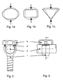
Fig. 1a einen unbelasteten runden und einen belasteten ovalen Querschnitt. -
Fig. 1b einen unbelasteten quadratischen und einen belasteten rechteckigen Querschnitt. -
Fig. 1c einen unbelasteten dreieckigen und einen belasteten dreieckigen Querschnitt mit verbreiteter Basis. -
Fig. 2 ein beispielsweise rundes Verbindungselement (2) in der Aufnahme einer Pedikelschraube (1) mit einem Füllstück (3) und einem Klemmelement (4). -
Fig. 3 eine Seitenansicht vonFig. 2 . -
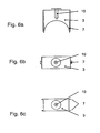
Fig. 4 einen Schnitt vonFig. 2 mit lokalen Abweichungen vom Querschnitt des Verbindungselementes entlang der Aufnahme (5a, 5b, 6a, 6b). -
Fig. 5 die nicht die Erfindung zeigt, zeigt einen Schnitt vonFig. 2 mit zapfenförmigen Abweichungen (8, 9) vom Querschnitt des Verbindungselementes (2) entlang der Aufnahme an der Schraube (1) und am Füllstück (3). -
Fig. 6a ein Füllstück (3) mit einer beispielsweisen Aufnahme (10) für ein Gegenhalteinstrument. -
Fig. 6b eine Draufsicht vonFig. 6a . -
Fig. 6c dieselbe Draufsicht wieFig. 6b , jedoch mit einer alternativen seitlichen Führung (7). -
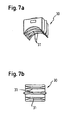
Fig. 7a eine perspektivische Ansicht eines Füllstücks gemäß einer Abwandlung. -
Fig. 7b eine Ansicht des Füllstücks ausFig. 7a von unten. -
Fig. 1 a stellt zum Beispiel einen runden Querschnitt dar, der durch zwei gegenüberliegende Kräfte in eine neue Form, nämlich einen ovalen Querschnitt übergeführt wird. -
Fig. 1b stellt zum Beispiel einen quadratischen Querschnitt dar, der durch zwei gegenüberliegende Kräfte in eine neue Form, nämlich einen rechteckigen Querschnitt übergeführt wird. -
Fig. 1c stellt zum Beispiel einen dreieckigen Querschnitt dar, der durch zwei gegenüberliegende Kräfte in eine neue Form, nämlich wiederum ein Dreieck mit spitzeren Basiswinkel übergeführt wird. -
Fig. 2 zeigt einen beispielsweisen runden Stab (2) in der Aufnahme einer Pedikelschraube (1), der über ein Füllstück (3) durch beispielsweise eine Mutter (4) als Klemmelement eingespannt wird. -
Fig. 3 zeigt dieselben Gegenstände wieFig. 2 , jedoch in einer Seitenansicht. -
Fig. 4 zeigt einen Schnitt vonFig. 2 in welchem der Kontaktbereich in einem oder mehreren Schnitte vom Ausgangsquerschnitt des beispielsweisen runden Stabes (2) als beispielsweises Verbindungselement gezielt abweicht, indem zum Beispiel eine erhöhte Rippe unten (5a) an der Schraube (1) und oben (5b) am Füllstück (3) angebracht werden. Hierbei wird das Verbindungselement durch die Mutter (4) als beispielsweises Klemmelement über das beispielsweise seitlich geführte (7) Füllstück (3) zusammengedrückt. Zur Aufnahme des derart verdrängten Materials werden entsprechende Vertiefungen links (6a) und rechts (6b) je an der Schraube (1) und Füllstück (3) angebracht, so dass das verdrängte Material in die Vertiefungen (6a, 6b) fließen kann und somit einen Anteil Formschluss bewirken kann. -
Fig. 5 zeigt einen Schnitt vonFig. 2 in welchem die Erhöhungen (5a, 5b) gemäßFig. 4 zu einem oder mehreren konischen Zapfen (8) an der Schraube (1) respektive einem oder mehreren konischen Zapfen (9) am seitlich geführten (7) Füllstück (3) reduziert werden. Hierbei dringen die konischen Zapfen (8, 9) derart in den elastischen Kunststoff ein, dass ein Anteil Formschluss entsteht. -
Fig. 6a zeigt eine Seitenansicht eines Füllstückes (3) mit einer beispielsweisen seitlichen Führung (7) und einer beispielsweisen Aufnahme für ein Gegenhalteinstrument (10). -
Fig. 6b zeigt eine Draufsicht vonFig. 6a . -
Fig. 6c zeigt in einer weiteren Draufsicht vonFig. 6a eine alternative seitliche Führung (7). - Eine weitere Abwandlung des Füllstücks ist in den
Figuren 7a und 7b dargestellt. Das Füllstück 30 unterscheidet sich von dem zuvor beschriebenen Füllstück darin, dass auf der dem Verbindungselement 2 zugewandten Seite mehrere vorspringende Rippen 31 ausgebildet sind, die jeweils senkrecht zur Längsachse des Verbindungselements 2 verlaufen. In dem dargestellten Beispiel sind drei vorspringende Rippen 31 parallel zueinander und gleichmäßig beabstandet ausgebildet. Es können jedoch auch mehr oder weniger Rippen vorhanden sein. Die Abstände können variieren. - Entsprechend zu den Rippen im Füllstück 30 können in der Aufnahme der Schraube 1 ebenfalls mehrere vorspringende Rippen vorgesehen sein, die senkrecht zur Längsachse des Verbindungselements 2 verlaufen. Die Ausbildung von mehreren solchen Rippen führt zu einer verbesserten Lastverteilung an der Oberfläche des Verbindungselements 2.
- Die Anzahl der Rippen am Füllstück und in der Aufnahme der Schraube können voneinander verschieden sein.
Claims (7)
- Wirbelsäulenimplantat, bestehend aus einem Verbindungselement (2), mehreren Knochenschranben (1) mit je einer Aufnahme für dieses Verbindungselement, je einem seitlich geführten Füllstück (3) und je einem Klemmelement (4) derart, dass das Verbindungselement (2) zwischen der Aufnahme im Schraubenkopf und dem Füllstück (3) durch das Klemmelement (4) kraftschlüssig geklemmt wird, wobei die Kontur im Bereich der unteren Aufnahme am Schraubenkopf (5a) und im Bereich der oberen Aufnahme am Füllstück (5b) von der Kontur des Verbindungselementes abweicht, wobei das Verbindungselement (2) als elastischer Kunststoffstab mit kontinuierlicher glatter Oberfläche ausgebildet ist,
dadurch gekennzeichnet, dass die Kontur auch im Bereich der seitlichen Aufnahmen am Schraubenkopf und Füllstück (6a, 6b) von derjenigen des Verbindungselementes abweicht und wobei die oberen und unteren Abweichungen vorstehend (5a 5b) und die seitlichen Abweichungen vertieft (6a, 6b) sind. - Wirbelsäulenimplantat nach Anspruch 1, dadurch gekennzeichnet, dass sich die Abweichungen der Kontur in einem oder mehreren Schnitten quer zur Längsache des Verbindungselementes, in derselben Ebene oder in verschiedenen Ebenen befinden.
- Wirbelsäulenimplantat nach einem der Anspruch 1 oder 2, dadurch gekennzeichnet, dass die Abweichungen von der Kontur rippenförmig (5a, 5b, 6a, 6b) oder zapfenförmig (8, 9) sind.
- Wirbelsäulenimplantat nach einem der Ansprüche 1 bis 3, dadurch gekennzeichnet, dass der Stab rund ist.
- Wirbelsäulenimplantat nach einem der Ansprüche 1 bis 4, dadurch gekennzeichnet, dass das Verbindungselement (2) aus PCU (polycarbonateurethane) gefertigt ist.
- Wirbelsäulenimplantat nach einem der Ansprüche 1 bis 5, dadurch gekennzeichnet, dass das Klemmelement (4) eine Mutter ist.
- Witbelsäutenimplantat nach einem der Ansprüche 1 bis 6, dadurch gekennzeichnet, dass das Füllstück (3) eine Aufnahme für ein Halteinstrument (10) aufweist.
Applications Claiming Priority (2)
| Application Number | Priority Date | Filing Date | Title |
|---|---|---|---|
| CH01409/05A CH705709B1 (de) | 2005-08-29 | 2005-08-29 | Wirbelsäulenimplantat. |
| US73869505P | 2005-11-21 | 2005-11-21 |
Publications (3)
| Publication Number | Publication Date |
|---|---|
| EP1759646A1 EP1759646A1 (de) | 2007-03-07 |
| EP1759646B1 EP1759646B1 (de) | 2008-07-30 |
| EP1759646B2 true EP1759646B2 (de) | 2011-03-16 |
Family
ID=36406026
Family Applications (1)
| Application Number | Title | Priority Date | Filing Date |
|---|---|---|---|
| EP06018027A Not-in-force EP1759646B2 (de) | 2005-08-29 | 2006-08-29 | Kraftschlüssige Schrauben-/Stabverbindung mit durch Verformung induziertem Formschlussanteil |
Country Status (8)
| Country | Link |
|---|---|
| US (2) | US8282672B2 (de) |
| EP (1) | EP1759646B2 (de) |
| JP (1) | JP4813293B2 (de) |
| KR (1) | KR101280008B1 (de) |
| CN (1) | CN101011289B (de) |
| CH (1) | CH705709B1 (de) |
| ES (1) | ES2312071T5 (de) |
| TW (1) | TWI436755B (de) |
Families Citing this family (52)
| Publication number | Priority date | Publication date | Assignee | Title |
|---|---|---|---|---|
| DE502006002049D1 (de) * | 2005-09-13 | 2008-12-24 | Bird Biedermann Ag | Dynamische Klemmvorrichtung für Wirbelsäulenimplantat |
| DE602005008752D1 (de) | 2005-11-17 | 2008-09-18 | Biedermann Motech Gmbh | Polyaxialschraube für flexiblen Stab |
| US7819899B2 (en) * | 2006-01-03 | 2010-10-26 | Zimmer Spine, Inc. | Instrument for pedicle screw adhesive materials |
| EP1815812B1 (de) * | 2006-02-03 | 2009-07-29 | Spinelab AG | Wirbelsäulenimplantat |
| US8043337B2 (en) | 2006-06-14 | 2011-10-25 | Spartek Medical, Inc. | Implant system and method to treat degenerative disorders of the spine |
| EP1891904B1 (de) * | 2006-08-24 | 2013-12-25 | Biedermann Technologies GmbH & Co. KG | Knochenverankerungsvorrichtung |
| ES2336815T5 (es) * | 2006-09-15 | 2013-05-16 | Biedermann Technologies Gmbh & Co. Kg | Dispositivo de anclaje óseo |
| US8636783B2 (en) * | 2006-12-29 | 2014-01-28 | Zimmer Spine, Inc. | Spinal stabilization systems and methods |
| EP2117451A1 (de) * | 2006-12-29 | 2009-11-18 | Zimmer Spine Austin, Inc. | Wirbelsäulenstabilisierungssysteme und -verfahren |
| ES2392351T3 (es) * | 2007-02-23 | 2012-12-07 | Biedermann Technologies Gmbh & Co. Kg | Dispositivo para estabilizar vértebras |
| US8048121B2 (en) | 2007-06-05 | 2011-11-01 | Spartek Medical, Inc. | Spine implant with a defelction rod system anchored to a bone anchor and method |
| US8092501B2 (en) | 2007-06-05 | 2012-01-10 | Spartek Medical, Inc. | Dynamic spinal rod and method for dynamic stabilization of the spine |
| US8021396B2 (en) | 2007-06-05 | 2011-09-20 | Spartek Medical, Inc. | Configurable dynamic spinal rod and method for dynamic stabilization of the spine |
| US8070776B2 (en) | 2007-06-05 | 2011-12-06 | Spartek Medical, Inc. | Deflection rod system for use with a vertebral fusion implant for dynamic stabilization and motion preservation spinal implantation system and method |
| US8114134B2 (en) | 2007-06-05 | 2012-02-14 | Spartek Medical, Inc. | Spinal prosthesis having a three bar linkage for motion preservation and dynamic stabilization of the spine |
| US8147520B2 (en) | 2007-06-05 | 2012-04-03 | Spartek Medical, Inc. | Horizontally loaded dynamic stabilization and motion preservation spinal implantation system and method |
| US8048115B2 (en) | 2007-06-05 | 2011-11-01 | Spartek Medical, Inc. | Surgical tool and method for implantation of a dynamic bone anchor |
| US8083772B2 (en) | 2007-06-05 | 2011-12-27 | Spartek Medical, Inc. | Dynamic spinal rod assembly and method for dynamic stabilization of the spine |
| US8105359B2 (en) | 2007-06-05 | 2012-01-31 | Spartek Medical, Inc. | Deflection rod system for a dynamic stabilization and motion preservation spinal implantation system and method |
| ES2375539T3 (es) * | 2007-07-20 | 2012-03-01 | Biedermann Motech Gmbh | Dispositivo de anclaje óseo. |
| US20090105756A1 (en) | 2007-10-23 | 2009-04-23 | Marc Richelsoph | Spinal implant |
| ES2359756T3 (es) | 2008-01-28 | 2011-05-26 | Spinelab Ag | Tornillo pedicular con dispositivo de cierre. |
| US8337536B2 (en) | 2008-02-26 | 2012-12-25 | Spartek Medical, Inc. | Load-sharing bone anchor having a deflectable post with a compliant ring and method for stabilization of the spine |
| US8016861B2 (en) | 2008-02-26 | 2011-09-13 | Spartek Medical, Inc. | Versatile polyaxial connector assembly and method for dynamic stabilization of the spine |
| US8083775B2 (en) | 2008-02-26 | 2011-12-27 | Spartek Medical, Inc. | Load-sharing bone anchor having a natural center of rotation and method for dynamic stabilization of the spine |
| US8097024B2 (en) | 2008-02-26 | 2012-01-17 | Spartek Medical, Inc. | Load-sharing bone anchor having a deflectable post and method for stabilization of the spine |
| US8267979B2 (en) | 2008-02-26 | 2012-09-18 | Spartek Medical, Inc. | Load-sharing bone anchor having a deflectable post and axial spring and method for dynamic stabilization of the spine |
| US8057515B2 (en) | 2008-02-26 | 2011-11-15 | Spartek Medical, Inc. | Load-sharing anchor having a deflectable post and centering spring and method for dynamic stabilization of the spine |
| US20100030224A1 (en) | 2008-02-26 | 2010-02-04 | Spartek Medical, Inc. | Surgical tool and method for connecting a dynamic bone anchor and dynamic vertical rod |
| US8333792B2 (en) | 2008-02-26 | 2012-12-18 | Spartek Medical, Inc. | Load-sharing bone anchor having a deflectable post and method for dynamic stabilization of the spine |
| US8211155B2 (en) | 2008-02-26 | 2012-07-03 | Spartek Medical, Inc. | Load-sharing bone anchor having a durable compliant member and method for dynamic stabilization of the spine |
| DE602008002815D1 (de) * | 2008-03-28 | 2010-11-11 | Biedermann Motech Gmbh | Knochenverankerungsvorrichtung |
| US20090326582A1 (en) * | 2008-04-10 | 2009-12-31 | Marcus Songer | Dynamic Rod |
| EP2113216B1 (de) * | 2008-04-28 | 2012-05-30 | Biedermann Technologies GmbH & Co. KG | Stabförmiges Element zur Wirbelsäulenstabilisierung und Verfahren zu dessen Herstellung |
| DE602008004213D1 (de) | 2008-05-06 | 2011-02-10 | Biedermann Motech Gmbh | Stangenförmiges Implantat, insbesondere zur dynamischen Stabilisierung der Wirbelsäule |
| EP2135574B1 (de) * | 2008-06-19 | 2011-10-12 | BIEDERMANN MOTECH GmbH | Knochenverankerungsanordnung |
| EP2160988B1 (de) | 2008-09-04 | 2012-12-26 | Biedermann Technologies GmbH & Co. KG | Stangenförmiges Implantat, insbesondere zur Stabilisierung der Wirbelsäule, und Stabilisierungsvorrichtung mit einem derartigen stangenförmigen Implantat |
| US9603629B2 (en) | 2008-09-09 | 2017-03-28 | Intelligent Implant Systems Llc | Polyaxial screw assembly |
| US8979905B2 (en) * | 2008-09-10 | 2015-03-17 | Life Spine, Inc. | Spinal rod |
| KR101697492B1 (ko) * | 2009-07-16 | 2017-01-18 | 스파인세이브 아게 | 척추의 안정화를 위한 연결 봉재용 고정 배열체 |
| CN102695465A (zh) | 2009-12-02 | 2012-09-26 | 斯帕泰克医疗股份有限公司 | 结合具有可偏转柱和复合脊柱杆的骨锚固件的小轮廓脊柱假体 |
| US20110307015A1 (en) | 2010-06-10 | 2011-12-15 | Spartek Medical, Inc. | Adaptive spinal rod and methods for stabilization of the spine |
| EP2670321B1 (de) * | 2011-02-04 | 2017-05-10 | Spinesave AG | Vorkehrung gegen verkanten an offenen knochenschrauben |
| ES2569854T3 (es) | 2011-09-28 | 2016-05-12 | Biedermann Technologies Gmbh & Co. Kg | Conjunto de anclaje de hueso |
| JP2014533136A (ja) | 2011-10-05 | 2014-12-11 | マーク・エイ・ドッドソン | モジュール開創器および関連する方法 |
| US8430916B1 (en) | 2012-02-07 | 2013-04-30 | Spartek Medical, Inc. | Spinal rod connectors, methods of use, and spinal prosthesis incorporating spinal rod connectors |
| EP2826429B1 (de) | 2013-07-19 | 2016-09-14 | Biedermann Technologies GmbH & Co. KG | Polyaxiale Knochenverankerungsvorrichtung |
| US9044273B2 (en) | 2013-10-07 | 2015-06-02 | Intelligent Implant Systems, Llc | Polyaxial plate rod system and surgical procedure |
| CN106137471B (zh) * | 2015-04-24 | 2020-02-18 | 施鲁孙 | 应力分散式人工椎间盘 |
| CN105455927B (zh) * | 2016-01-13 | 2017-06-20 | 李海明 | 一种脊柱植入物用双向预应力夹紧装置及其安装方法 |
| CN105496540B (zh) * | 2016-01-20 | 2019-04-26 | 北京大学深圳医院 | 具有骨诱导材料涂层的髂骨钉及脊椎固定装置 |
| CN107007341B (zh) * | 2017-05-22 | 2020-02-11 | 浙江德康医疗器械有限公司 | 一种钴铬钼胸腰后路钉棒系统 |
Citations (1)
| Publication number | Priority date | Publication date | Assignee | Title |
|---|---|---|---|---|
| US172025A (en) † | 1876-01-11 | Improvement in sulky-plows |
Family Cites Families (43)
| Publication number | Priority date | Publication date | Assignee | Title |
|---|---|---|---|---|
| US4743260A (en) * | 1985-06-10 | 1988-05-10 | Burton Charles V | Method for a flexible stabilization system for a vertebral column |
| FR2633177B1 (fr) * | 1988-06-24 | 1991-03-08 | Fabrication Materiel Orthopedi | Implant pour dispositif d'osteosynthese rachidienne, notamment en traumatologie |
| FR2658414B1 (fr) | 1990-02-19 | 1992-07-31 | Sofamor | Implant pour dispositif d'osteosynthese en particulier du rachis. |
| WO1991016020A1 (en) * | 1990-04-26 | 1991-10-31 | Danninger Medical Technology, Inc. | Transpedicular screw system and method of use |
| CH681853A5 (de) * | 1990-08-21 | 1993-06-15 | Synthes Ag | |
| US5257993A (en) * | 1991-10-04 | 1993-11-02 | Acromed Corporation | Top-entry rod retainer |
| DE59301618D1 (de) | 1992-06-04 | 1996-03-28 | Synthes Ag | Osteosynthetisches Befestigungselement |
| US5545165A (en) | 1992-10-09 | 1996-08-13 | Biedermann Motech Gmbh | Anchoring member |
| DE4234118C2 (de) | 1992-10-09 | 2002-09-19 | Biedermann Motech Gmbh | Verankerungselement |
| ZA937672B (en) * | 1992-10-22 | 1994-05-16 | Danek Medical Inc | Spinal rod transverse connector for supporting vertebral fixation elements |
| DE4307576C1 (de) | 1993-03-10 | 1994-04-21 | Biedermann Motech Gmbh | Knochenschraube |
| US6077262A (en) * | 1993-06-04 | 2000-06-20 | Synthes (U.S.A.) | Posterior spinal implant |
| DE59310397D1 (de) | 1993-07-02 | 2009-07-09 | Synthes Gmbh | Posteriores Wirbelsäulenimplantat |
| ES2133517T3 (es) | 1994-02-28 | 1999-09-16 | Sulzer Orthopadie Ag | Estabilizador para vertebras adyacentes. |
| EP0689798B1 (de) | 1994-06-30 | 2000-10-18 | Sulzer Orthopädie AG | Vorrichtung zum Verbinden von Wirbelknochen |
| DE4425357C2 (de) * | 1994-07-18 | 1996-07-04 | Harms Juergen | Verankerungselement |
| US5562663A (en) * | 1995-06-07 | 1996-10-08 | Danek Medical, Inc. | Implant interconnection mechanism |
| FR2739548A1 (fr) | 1995-10-05 | 1997-04-11 | Huitema Jean Pierre | Dispositif de serrage concernant les vis pediculaires et les crochets laminaires dans le cadre des operations du rachis |
| US5782833A (en) | 1996-12-20 | 1998-07-21 | Haider; Thomas T. | Pedicle screw system for osteosynthesis |
| US6749361B2 (en) * | 1997-10-06 | 2004-06-15 | Werner Hermann | Shackle element for clamping a fixation rod, a method for making a shackle element, a hook with a shackle element and a rode connector with a shackle element |
| DE19818765A1 (de) * | 1998-04-07 | 1999-10-14 | Schaefer Micomed Gmbh | Osteosynthesevorrichtung |
| US6565565B1 (en) * | 1998-06-17 | 2003-05-20 | Howmedica Osteonics Corp. | Device for securing spinal rods |
| IT1310423B1 (it) | 1999-07-29 | 2002-02-13 | Giovanni Zaccherotti | Mezzo di fissazione femorale dei tendini di semitendinoso e delgragile per la ricostruzione del legamento crociato anteriore. |
| AU1493301A (en) | 1999-09-27 | 2001-04-30 | Blackstone Medical, Inc. | A surgical screw system and related methods |
| US6554834B1 (en) | 1999-10-07 | 2003-04-29 | Stryker Spine | Slotted head pedicle screw assembly |
| US6302410B1 (en) | 1999-10-22 | 2001-10-16 | Earth Tool Company, L.L.C. | Rod gripping jaw |
| US6224598B1 (en) | 2000-02-16 | 2001-05-01 | Roger P. Jackson | Bone screw threaded plug closure with central set screw |
| US6478797B1 (en) * | 2001-05-16 | 2002-11-12 | Kamaljit S. Paul | Spinal fixation device |
| US6520963B1 (en) * | 2001-08-13 | 2003-02-18 | Mckinley Lawrence M. | Vertebral alignment and fixation assembly |
| DE60144067D1 (de) | 2001-08-13 | 2011-03-31 | Laurence M Mckinley | Wirbelausrichtungs- und fixierungsanordnung |
| US6652526B1 (en) | 2001-10-05 | 2003-11-25 | Ruben P. Arafiles | Spinal stabilization rod fastener |
| US6783527B2 (en) | 2001-10-30 | 2004-08-31 | Sdgi Holdings, Inc. | Flexible spinal stabilization system and method |
| DE10213855A1 (de) * | 2002-03-27 | 2003-10-16 | Biedermann Motech Gmbh | Knochenverankerungsvorrichtung zum Stabilisieren von Knochensegmenten und Aufnahmeteil einer Knochenverankerungsvorrichtung |
| DE50300788D1 (de) | 2002-05-21 | 2005-08-25 | Spinelab Gmbh Wabern | Elastisches Stabilisiersystem für Wirbelsäulen |
| US20030220643A1 (en) | 2002-05-24 | 2003-11-27 | Ferree Bret A. | Devices to prevent spinal extension |
| US6843791B2 (en) * | 2003-01-10 | 2005-01-18 | Depuy Acromed, Inc. | Locking cap assembly for spinal fixation instrumentation |
| ES2269957T3 (es) * | 2003-10-31 | 2007-04-01 | Spinelab Ag | Mecanismo de cierre de tornillos pediculares dpara la fijacion de varillas elasticas. |
| TW200518711A (en) | 2003-12-11 | 2005-06-16 | A Spine Holding Group Corp | Rotation buckling ball-head spine restoring equipment |
| DE102004010844A1 (de) * | 2004-03-05 | 2005-10-06 | Biedermann Motech Gmbh | Stabilisierungseinrichtung zur dynamischen Stabilisierung von Wirbeln oder Knochen und stabförmiges Element für eine derartige Stabilisierungseinrichtung |
| DE502006002049D1 (de) | 2005-09-13 | 2008-12-24 | Bird Biedermann Ag | Dynamische Klemmvorrichtung für Wirbelsäulenimplantat |
| DE602005008752D1 (de) | 2005-11-17 | 2008-09-18 | Biedermann Motech Gmbh | Polyaxialschraube für flexiblen Stab |
| ES2309646T3 (es) | 2005-12-23 | 2008-12-16 | Biedermann Motech Gmbh | Dispositivo estabilizador flexible para la estabilizacion dinamica de huesos o vertebras. |
| ES2336815T5 (es) | 2006-09-15 | 2013-05-16 | Biedermann Technologies Gmbh & Co. Kg | Dispositivo de anclaje óseo |
-
2005
- 2005-08-29 CH CH01409/05A patent/CH705709B1/de not_active IP Right Cessation
-
2006
- 2006-08-28 JP JP2006230330A patent/JP4813293B2/ja not_active Expired - Fee Related
- 2006-08-28 KR KR1020060081634A patent/KR101280008B1/ko not_active IP Right Cessation
- 2006-08-29 CN CN2006101495327A patent/CN101011289B/zh not_active Expired - Fee Related
- 2006-08-29 EP EP06018027A patent/EP1759646B2/de not_active Not-in-force
- 2006-08-29 US US11/512,461 patent/US8282672B2/en not_active Expired - Fee Related
- 2006-08-29 TW TW095131654A patent/TWI436755B/zh not_active IP Right Cessation
- 2006-08-29 ES ES06018027T patent/ES2312071T5/es active Active
-
2012
- 2012-08-28 US US13/596,888 patent/US20130079824A1/en not_active Abandoned
Patent Citations (1)
| Publication number | Priority date | Publication date | Assignee | Title |
|---|---|---|---|---|
| US172025A (en) † | 1876-01-11 | Improvement in sulky-plows |
Also Published As
| Publication number | Publication date |
|---|---|
| JP2007061615A (ja) | 2007-03-15 |
| KR20070026058A (ko) | 2007-03-08 |
| TW200718390A (en) | 2007-05-16 |
| KR101280008B1 (ko) | 2013-06-28 |
| US20070093820A1 (en) | 2007-04-26 |
| US8282672B2 (en) | 2012-10-09 |
| CN101011289A (zh) | 2007-08-08 |
| EP1759646A1 (de) | 2007-03-07 |
| ES2312071T5 (es) | 2011-07-20 |
| CN101011289B (zh) | 2010-05-19 |
| CH705709B1 (de) | 2013-05-15 |
| TWI436755B (zh) | 2014-05-11 |
| US20130079824A1 (en) | 2013-03-28 |
| EP1759646B1 (de) | 2008-07-30 |
| ES2312071T3 (es) | 2009-02-16 |
| JP4813293B2 (ja) | 2011-11-09 |
Similar Documents
| Publication | Publication Date | Title |
|---|---|---|
| EP1759646B2 (de) | Kraftschlüssige Schrauben-/Stabverbindung mit durch Verformung induziertem Formschlussanteil | |
| EP1667591B1 (de) | Vorrichtung zur elastischen stabilisierung von wirbelkörpern | |
| DE102007042953B4 (de) | Orthopädisches Haltesystem | |
| EP0535315B1 (de) | Wirbelkörperplatzhalter | |
| EP1815812B1 (de) | Wirbelsäulenimplantat | |
| DE69818001T2 (de) | Osteosynthesesystem für wirbelarthrodese | |
| EP1514522B1 (de) | Knochenschraube | |
| EP0616512A1 (de) | Verankerungselement. | |
| EP2612041A1 (de) | Käfigmutter | |
| DE102006000948A1 (de) | Knochenplatte | |
| WO2015079011A1 (de) | Wirbelkörperersatzimplantat mit schneckengetriebe | |
| WO2005030065A1 (de) | Vorrichtung zur verbindung eines längsträgers mit einem knochen | |
| EP1764060A1 (de) | Zahnimplantat | |
| EP0232483B1 (de) | Vorrichtung zur stufenweisen Höhenverstellung eines Befestigungs- oder Umlenkpunktes für einen Sicherheitsgurt o. dgl. | |
| EP0524441A1 (de) | Klemmverbindung zum Verbinden zweier Konstruktionselemente für eine, insbesondere osteosynthetische Fixationsvorrichtung | |
| EP1382315A1 (de) | Zwischenwirbelimplantat | |
| DE102015010741A1 (de) | Polyaxiale Pedikelschraube mit kugelsegmentförmigem Kopf | |
| EP1126114B1 (de) | Verstellbares Scharnier | |
| EP2130993B1 (de) | Abstützvorrichtung, insbesondere Unterstellbock | |
| EP3100691B1 (de) | Uniplanares knochenverankerungselement | |
| EP2142409B1 (de) | Befestigungseinrichtung zur ausbildung einer schnittstelle von einem rohbau zu einem innenausbau bei einem schienenfahrzeug | |
| DE1190740B (de) | Die Belastung von Schraubenbolzen anzeigende Unterlegplatte | |
| EP0338124B1 (de) | Fahrbahnübergang | |
| EP2446780A1 (de) | Stuhl, insbesondere Bürostuhl | |
| EP2476917A1 (de) | System zur Verbindung von zwei Bauteilen, Haltebock hierfür, sowie Spiegelanordnung für Kraftfahrzeuge hiermit |
Legal Events
| Date | Code | Title | Description |
|---|---|---|---|
| PUAI | Public reference made under article 153(3) epc to a published international application that has entered the european phase |
Free format text: ORIGINAL CODE: 0009012 |
|
| AK | Designated contracting states |
Kind code of ref document: A1 Designated state(s): AT BE BG CH CY CZ DE DK EE ES FI FR GB GR HU IE IS IT LI LT LU LV MC NL PL PT RO SE SI SK TR |
|
| AX | Request for extension of the european patent |
Extension state: AL BA HR MK YU |
|
| 17P | Request for examination filed |
Effective date: 20070810 |
|
| 17Q | First examination report despatched |
Effective date: 20070918 |
|
| AKX | Designation fees paid |
Designated state(s): CH DE ES FR GB IT LI |
|
| GRAP | Despatch of communication of intention to grant a patent |
Free format text: ORIGINAL CODE: EPIDOSNIGR1 |
|
| GRAS | Grant fee paid |
Free format text: ORIGINAL CODE: EPIDOSNIGR3 |
|
| GRAA | (expected) grant |
Free format text: ORIGINAL CODE: 0009210 |
|
| AK | Designated contracting states |
Kind code of ref document: B1 Designated state(s): CH DE ES FR GB IT LI |
|
| REG | Reference to a national code |
Ref country code: GB Ref legal event code: FG4D Free format text: NOT ENGLISH |
|
| REG | Reference to a national code |
Ref country code: CH Ref legal event code: EP |
|
| REF | Corresponds to: |
Ref document number: 502006001220 Country of ref document: DE Date of ref document: 20080911 Kind code of ref document: P |
|
| REG | Reference to a national code |
Ref country code: CH Ref legal event code: NV Representative=s name: NOVAGRAAF INTERNATIONAL SA |
|
| REG | Reference to a national code |
Ref country code: ES Ref legal event code: FG2A Ref document number: 2312071 Country of ref document: ES Kind code of ref document: T3 |
|
| PLBI | Opposition filed |
Free format text: ORIGINAL CODE: 0009260 |
|
| 26 | Opposition filed |
Opponent name: SPINELAB AG Effective date: 20090421 |
|
| PLAX | Notice of opposition and request to file observation + time limit sent |
Free format text: ORIGINAL CODE: EPIDOSNOBS2 |
|
| PLBB | Reply of patent proprietor to notice(s) of opposition received |
Free format text: ORIGINAL CODE: EPIDOSNOBS3 |
|
| PUAH | Patent maintained in amended form |
Free format text: ORIGINAL CODE: 0009272 |
|
| STAA | Information on the status of an ep patent application or granted ep patent |
Free format text: STATUS: PATENT MAINTAINED AS AMENDED |
|
| 27A | Patent maintained in amended form |
Effective date: 20110316 |
|
| AK | Designated contracting states |
Kind code of ref document: B2 Designated state(s): CH DE ES FR GB IT LI |
|
| REG | Reference to a national code |
Ref country code: CH Ref legal event code: AEN Free format text: AUFRECHTERHALTUNG DES PATENTES IN GEAENDERTER FORM |
|
| REG | Reference to a national code |
Ref country code: DE Ref legal event code: R102 Ref document number: 502006001220 Country of ref document: DE Effective date: 20110316 |
|
| REG | Reference to a national code |
Ref country code: CH Ref legal event code: PFA Owner name: BIRD BIEDERMANN AG Free format text: BIRD BIEDERMANN AG#BIRKENWEG 5#6072 SACHSELN (CH) -TRANSFER TO- BIRD BIEDERMANN AG#BIRKENWEG 5#6072 SACHSELN (CH) |
|
| REG | Reference to a national code |
Ref country code: ES Ref legal event code: DC2A Ref document number: 2312071 Country of ref document: ES Kind code of ref document: T5 Effective date: 20110720 |
|
| REG | Reference to a national code |
Ref country code: FR Ref legal event code: PLFP Year of fee payment: 10 |
|
| PGFP | Annual fee paid to national office [announced via postgrant information from national office to epo] |
Ref country code: GB Payment date: 20150824 Year of fee payment: 10 Ref country code: ES Payment date: 20150825 Year of fee payment: 10 Ref country code: CH Payment date: 20150824 Year of fee payment: 10 Ref country code: DE Payment date: 20150828 Year of fee payment: 10 |
|
| PGFP | Annual fee paid to national office [announced via postgrant information from national office to epo] |
Ref country code: FR Payment date: 20150824 Year of fee payment: 10 |
|
| PGFP | Annual fee paid to national office [announced via postgrant information from national office to epo] |
Ref country code: IT Payment date: 20150827 Year of fee payment: 10 |
|
| REG | Reference to a national code |
Ref country code: DE Ref legal event code: R119 Ref document number: 502006001220 Country of ref document: DE |
|
| REG | Reference to a national code |
Ref country code: CH Ref legal event code: PL |
|
| GBPC | Gb: european patent ceased through non-payment of renewal fee |
Effective date: 20160829 |
|
| PG25 | Lapsed in a contracting state [announced via postgrant information from national office to epo] |
Ref country code: LI Free format text: LAPSE BECAUSE OF NON-PAYMENT OF DUE FEES Effective date: 20160831 Ref country code: CH Free format text: LAPSE BECAUSE OF NON-PAYMENT OF DUE FEES Effective date: 20160831 |
|
| REG | Reference to a national code |
Ref country code: FR Ref legal event code: ST Effective date: 20170428 |
|
| PG25 | Lapsed in a contracting state [announced via postgrant information from national office to epo] |
Ref country code: GB Free format text: LAPSE BECAUSE OF NON-PAYMENT OF DUE FEES Effective date: 20160829 Ref country code: DE Free format text: LAPSE BECAUSE OF NON-PAYMENT OF DUE FEES Effective date: 20170301 Ref country code: FR Free format text: LAPSE BECAUSE OF NON-PAYMENT OF DUE FEES Effective date: 20160831 |
|
| PG25 | Lapsed in a contracting state [announced via postgrant information from national office to epo] |
Ref country code: IT Free format text: LAPSE BECAUSE OF NON-PAYMENT OF DUE FEES Effective date: 20160829 |
|
| PG25 | Lapsed in a contracting state [announced via postgrant information from national office to epo] |
Ref country code: ES Free format text: LAPSE BECAUSE OF NON-PAYMENT OF DUE FEES Effective date: 20160830 |
|
| REG | Reference to a national code |
Ref country code: ES Ref legal event code: FD2A Effective date: 20181203 |