EP1758320A1 - Forwarding table management in ethernet switch - Google Patents
Forwarding table management in ethernet switch Download PDFInfo
- Publication number
- EP1758320A1 EP1758320A1 EP06076558A EP06076558A EP1758320A1 EP 1758320 A1 EP1758320 A1 EP 1758320A1 EP 06076558 A EP06076558 A EP 06076558A EP 06076558 A EP06076558 A EP 06076558A EP 1758320 A1 EP1758320 A1 EP 1758320A1
- Authority
- EP
- European Patent Office
- Prior art keywords
- port
- switch
- ingress
- ethernet
- network connection
- Prior art date
- Legal status (The legal status is an assumption and is not a legal conclusion. Google has not performed a legal analysis and makes no representation as to the accuracy of the status listed.)
- Granted
Links
Images


Classifications
-
- H—ELECTRICITY
- H04—ELECTRIC COMMUNICATION TECHNIQUE
- H04L—TRANSMISSION OF DIGITAL INFORMATION, e.g. TELEGRAPHIC COMMUNICATION
- H04L49/00—Packet switching elements
- H04L49/30—Peripheral units, e.g. input or output ports
-
- H—ELECTRICITY
- H04—ELECTRIC COMMUNICATION TECHNIQUE
- H04L—TRANSMISSION OF DIGITAL INFORMATION, e.g. TELEGRAPHIC COMMUNICATION
- H04L45/00—Routing or path finding of packets in data switching networks
- H04L45/54—Organization of routing tables
-
- H—ELECTRICITY
- H04—ELECTRIC COMMUNICATION TECHNIQUE
- H04L—TRANSMISSION OF DIGITAL INFORMATION, e.g. TELEGRAPHIC COMMUNICATION
- H04L49/00—Packet switching elements
- H04L49/30—Peripheral units, e.g. input or output ports
- H04L49/3009—Header conversion, routing tables or routing tags
-
- H—ELECTRICITY
- H04—ELECTRIC COMMUNICATION TECHNIQUE
- H04L—TRANSMISSION OF DIGITAL INFORMATION, e.g. TELEGRAPHIC COMMUNICATION
- H04L49/00—Packet switching elements
- H04L49/30—Peripheral units, e.g. input or output ports
- H04L49/3018—Input queuing
-
- H—ELECTRICITY
- H04—ELECTRIC COMMUNICATION TECHNIQUE
- H04L—TRANSMISSION OF DIGITAL INFORMATION, e.g. TELEGRAPHIC COMMUNICATION
- H04L49/00—Packet switching elements
- H04L49/30—Peripheral units, e.g. input or output ports
- H04L49/3072—Packet splitting
-
- H—ELECTRICITY
- H04—ELECTRIC COMMUNICATION TECHNIQUE
- H04L—TRANSMISSION OF DIGITAL INFORMATION, e.g. TELEGRAPHIC COMMUNICATION
- H04L49/00—Packet switching elements
- H04L49/35—Switches specially adapted for specific applications
- H04L49/351—Switches specially adapted for specific applications for local area network [LAN], e.g. Ethernet switches
-
- H—ELECTRICITY
- H04—ELECTRIC COMMUNICATION TECHNIQUE
- H04L—TRANSMISSION OF DIGITAL INFORMATION, e.g. TELEGRAPHIC COMMUNICATION
- H04L49/00—Packet switching elements
- H04L49/35—Switches specially adapted for specific applications
- H04L49/354—Switches specially adapted for specific applications for supporting virtual local area networks [VLAN]
Definitions
- This invention relates to Ethernet switches and to a method of operating such a switch
- Packet-switched networks such as Internet Protocol (IP) or Ethernet networks are intrinsically connectionless in nature and, as a result, suffer from Quality of Service (QoS) problems.
- QoS Quality of Service
- Ethernet switches in carriers' networks.
- Use of Ethernet switches in carriers' networks would have the advantages of interoperability, since mappings between Ethernet and other frame/packet/cell data structures such as IP, Frame Relay are well known, and economy, since Ethernet switches are relatively inexpensive compared to IP routers, for example. It would also provide a distinct advantage of being the principal technology used by enterprises that require a wide area network service from a carrier and therefore able to work in a native mode.
- a conventional high-capacity Ethernet switch has a set of input ports and a set of output ports which are connected via a switch fabric.
- a conventional switched Ethernet network behaves like a 'classic' Ethernet Local Area Network (LAN) in that every Ethernet frame is broadcast across the entire network. Every switch, upon receiving an Ethernet frame on one port, broadcasts the frame out on every other port. The process repeats as the frame is received by other switches, thus broadcasting the frame across the entire network.
- LAN Local Area Network
- Every switch upon receiving an Ethernet frame on one port, broadcasts the frame out on every other port. The process repeats as the frame is received by other switches, thus broadcasting the frame across the entire network.
- MAC Medium Access Control
- Ethernet frames have source and destination MAC addresses corresponding to their source and destination Ethernet ports.
- the receiving switch When an Ethernet frame sent out by a source switch is received by an intermediate or destination Ethernet switch the receiving switch observes the port on which the frame was received and the source address of the frame. The switch then builds a forwarding table for use in future frame switching. Once a MAC address has been seen on a port, that information is made available to all ports to be used if any encounters that address.
- a central processor builds a single Forwarding Database (FDB) on the basis of MAC addresses seen on all ports. Over time, the network builds up forwarding state enabling efficient switching of Ethernet frames, without relying on broadcast any further.
- FDB Forwarding Database
- the FDB is typically replicated into a memory located at each input port, and the copy of the FDB associated with each port is the same. This allows each port to route a received frame without waiting to access a shared Forwarding Database. The overall memory requirement becomes significant in situations where the switch has a large number of input and output ports and a large FDB.
- Ethernet networks are connectionless, i.e. no path through the network is pre-established for a frame, or group of frames, corresponding to a traffic flow.
- Patent Application PCT/GB2005/001332, filed 6 April 2005 describes a way of providing connection-oriented behaviour in Ethernet networks. Connections are provided across an Ethernet network by configuring, via a control plane or management interface, Ethernet switches to map received data frames to particular output ports.
- An Ethernet switch for use in an Ethernet network comprises a set of ingress ports for receiving data frames and a set of egress ports.
- a memory is associated with each ingress port and stores forwarding information indicating one or more of the egress ports to which data frames received by that ingress port should be forwarded.
- a control or management interface receives information about a network connection established, or to be established, through the switch.
- a switch controller causes forwarding information to be stored in a memory associated with a first ingress port which the network connection will use, on the basis of the received information about a network connection. Forwarding information is not stored in a memory associated with a second of the set of ingress ports which the network connection will not use.
- the switch controller causes forwarding information to be stored only in a memory associated with the one or more ingress ports which the network connection will use and not to be stored in a memory associated with any of the other ingress ports.
- forwarding information will cause a data frame arriving at an ingress port to be forwarded to multiple egress ports.
- traffic routes converge at the Ethernet switch, forwarding information will be stored at each of the multiple ingress ports where data frames of those routes will arrive, and the forwarding information will cause the data frames to be forwarded to a common egress port.
- a consequence of using Ethernet switches in a connection-oriented mode of operation is that frames associated with a particular routing across the network will leave a switch by a known port and can only arrive at the switch through a known port (or set of ports).
- the Forwarding Database (FDB) associated with each ingress port may therefore be individually populated, and contain only those entries which the Network Management System knows could be validly received on that port.
- FDB Forwarding Database
- the network can be scaled for a given memory size. Investigation of typical carrier deployment scenarios shows that the reduction in memory size can easily be a factor of four.
- an Ethernet switch comprises a set of bi-directional interface ports, each bi-directional interface port comprising an ingress port and an egress port.
- the switch fabric selectively interconnects the ingress port of one bi-directional interface port with the egress port of another bi-directional interface port. Normally the ingress port and egress port of a bi-directional interface port will share a common MAC address.
- a further aspect of the invention provides a port card comprising an ingress port for receiving data frames and a memory for storing forwarding information indicating one or more egress ports of the switch to which data frames received by the ingress port should be forwarded.
- the forwarding information stored in the memory relates only to network connections which use that ingress port.
- the port card typically supports a bi-directional port having an ingress port function and an egress port function.
- the port card may house a single ingress port (or bi-directional port) or multiple ports (or bi-directional ports).
- the plurality of ingress ports may share the same memory.
- a further aspect of the invention provides a port controller comprising control logic which is operable to receive forwarding information from the switch controller for a network connection which is established, or will be established, via the ingress port and update the forwarding information in the memory for that ingress port. The forwarding information is received on the basis of whether the network connection will use that ingress port.
- a still further aspect of the invention provides a switch controller comprising control logic which is operable to receive information about a network connection established, or to be established, through the switch; and cause forwarding information to be stored in a memory associated with a first ingress port which the network connection will use, on the basis of the received information about a network connection, and not to be stored in a memory associated with a second ingress port which the network connection will not use.
- This functionality can be implemented in software, hardware or a combination of these.
- the invention can be implemented by means of hardware comprising several distinct elements, and by means of a suitably programmed computer. Accordingly, another aspect of the invention provides software for providing the functions of the switch controller and/or port controller.
- the software may be stored on an electronic memory device, hard disk, optical disk or other machine-readable storage medium.
- the software may be delivered as a computer program product on a machine-readable carrier or it may be downloaded directly to the switch via a network connection.
- FIGS 1 and 2 show an arrangement of Ethernet switches and communications links forming a carrier network.
- Carrier network cloud 20 comprises Ethernet switches 22a, 22b, 24a, 24b, 26 and 28.
- Ethernet switches 22a, 22b and 26 are located at the edges of carrier network 20, whereas Ethernet switches 24a, 24b, and 28 are located in the core network.
- Communications links (shown as straight lines) are provided between Ethernet switches 22a, 22b, 24a, 24b, 26 and 28.
- These communications links may be for example relatively long distance links over optical equipment such as SONET/SDH equipment with Ethernet interfaces using Generic Framing Procedure (GFP) (ITU-T Recommendation G.7041/Y.1303).
- GFP Generic Framing Procedure
- core network switches 24a, 24b, and 28 are shown with a fully-meshed configuration, i.e. there is a direct communications link connecting each core network switch 24a, 24b, and 28 to each other, this is not essential.
- the carrier Ethernet network 20 provides connectivity between customer sites. Three customers having respective pairs of geographically distant Ethernet switches (40a and 40b, 42a and 42b, 44a and 44b) are shown connected to carrier network 20 via edge Ethernet switches 22a and 22b respectively.
- the communications links between edge switches 22a and 22b and customer switches 40a, 40b, 42a, 42b, 44a, and 44b may be dedicated links such as T1, E1 leased lines or access links such as digital Subscriber Lines (DSLs).
- Carrier edge switches 22a, 22b, 26 may be logically separated into a single Provider Edge- (PE-) Core and one or more PE-Edge functions.
- the PE-Edge is the ingress/egress point at which customer traffic enters or leaves the carrier network 20.
- the PE-Core preferentially encapsulates incoming Ethernet traffic from the customer using Media Access Control (MAC) in MAC encapsulation (or, if desired, Pseudo-Wire over MAC encapsulation) and forwards the encapsulated traffic across the carrier network 20.
- MAC Media Access Control
- This embodiment is preferred as a mechanism to limit the number of table entries required because only the MAC address space of the carrier network need be recognised, and not the whole of the customer's MAC address space, which could be changed independently.
- the PE-Core decapsulates (strips) outgoing Ethernet traffic and forwards the stripped traffic on to the customer via the appropriate PE-Edge.
- VLAN tags are often used to provide customer separation at the logical PE-Core with each different customer site connected to each edge switch having a unique VLAN tag. Stacked VLAN (i.e. VLAN-in-VLAN encapsulation or Q-in-Q) may be used to protect any VLAN tags used by the customer traffic.
- customer switch 42a may send Ethernet traffic over communications link 46a to the logical PE-Edge of edge switch 22a.
- Logical PE-Core of edge switch 22a encapsulates each Ethernet frame in a further Ethernet frame using the MAC address of the ingress port on edge switch 22a as the source address and the MAC address of the appropriate egress point - in this case a port on edge switch 22b - as the destination address.
- the encapsulated traffic is forwarded across a connection established over communications links 48 of carrier network 20 to edge switch 22b. Connections may be typically trunked in the sense that traffic from multiple customers will be routed through the same connection. Alternatively, those skilled in the art will appreciate that separate connections 48 could be used for each customer.
- the original frames are stripped of their encapsulation and sent over communications link 46b via PE-Edge of edge switch 22b to customer switch 42b.
- the logical PE-Edge may also be physically separated from the logical PE-Core and may reside at customer premises whereas the PE-Core would preferentially reside at a central office or Point of Presence (PoP) of the carrier.
- PoP Point of Presence
- edge switches may also have connections to customer sites and that customers may have to be provided with connectivity between two or more geographically distant sites over carrier network 20.
- a connection may be defined as an entity configured in a network which provides transport of data from a source node to one or more sink nodes.
- carrier network 20 may be at least partially-meshed - i.e. there will usually be more than one possible path between at least some, and preferably all, nodes of the network.
- broadcast and Ethernet MAC address auto learning functionality should be at least partially deactivated to permit loops to be formed safely in the network.
- LANs Local Area Networks
- Ethernet frames have source and destination MAC addresses corresponding to their source and destination Ethernet ports.
- An Ethernet port here is signifying an end system which is therefore configured with at least one MAC address.
- the receiving switch observes the port on which the frame was received and the source address of the frame. It then builds up a forwarding table for use in future frame switching.
- the forwarding table maps destination address to output port and is built up using the source address of a received frame and the input port on which it was received. Over time, the network builds up forwarding state enabling efficient switching of Ethernet frames, without relying on broadcast any further.
- FIG. 2 shows elements 32a, 34, 34b, 32b of a control plane/transport plane architecture for controlling the Ethernet carrier network of Figure 1.
- the ITU-T Automatically Switched Transport Network (ASTN), sometimes known as the Automatically Switched Optical Network (ASON), may be used as the control plane.
- ASSN Automatically Switched Transport Network
- ASON Automatically Switched Optical Network
- Control plane 30 comprises a number of connection controllers 32a, 32b, 34a, 34b, 36 and 38 corresponding to each of Ethernet switches 22a, 22b, 24a, 24b, 26 and 28 of carrier network 20.
- Control Plane 30 may be conceptually thought of as lying 'above' transport plane 32 which comprises the Ethernet switches 22a, 22b, 24a, 24b, 26 and 28 of carrier network 20.
- Connection controllers (CCs) are logical agents each corresponding to a respective Ethernet switch (which represent cross connects in ASTN terminology) in transport plane 32.
- Each CC controls the switching of its respective switch using Connection Control Interface (CCI) signalling (shown as dotted lines in Figure 2).
- CCI signalling is used to directly configure the forwarding tables used by Ethernet switches 22a, 22b, 24a, 24b, 26 and 28 of carrier network 20.
- CCs may communicate between themselves using a Network to Network Interface (NNI).
- NNI Network to Network Interface
- CCs will exchange information regarding their operational state and the state, in particular the capacity, of their communications links using NNI signalling.
- Other control plane functions such as heartbeat, ping and circuit monitoring may be provided using the ITU-T standard-in-preparation currently referred to as Y.17ethOAM or the methods in IEEE standard 802.lag.
- CCs 32a, 32b, 34a and 34b are logically separate from Ethernet switches 22a, 22b, 24a and 24b the reader will understand that they may be implemented in the same physical nodes in a distributed control plane model. Additionally, one CC may control one or more Ethernet switches which is moving towards a more centralised control plane model. Furthermore, NNI signalling may take place over the same communications links used for transporting user traffic.
- Figure 2 shows how control plane 30 interacts with transport plane 32 to establish a point-to-point connection across carrier network 20.
- the connection will be bi-directional, although this can simply be considered as the combination of two unidirectional point to point connections.
- a request to establish a connection specifying a required bandwidth and an explicit route across carrier network 20 is generated for example by a supervisory network management node (not shown) or distributed network management system or function.
- the explicit route will have been determined in accordance with a conventional routing protocol taking into account the topology of the carrier network, the operational state of network resources and the bandwidth requirements of existing and possible future connections.
- the route to be taken by the exemplary connection shown in Figure 2 spans Ethernet switches 22a, 24a, 24b and 22b over communications links 48.
- the route may also be established by direct NNI signalling between CCs in an ad-hoc fashion.
- the request to establish a connection is first sent to CC 32a.
- CC 32a checks whether the communications link between switches 22a and 24a has sufficient capacity to support the required bandwidth. If so, it forwards a connection setup request message 50 to CC 34a specifying the required bandwidth and explicit route.
- CC 34a then checks whether the communications link between switches 24a and 24b has sufficient capacity to support the required bandwidth. The process continues until the connection setup message request 50 reaches CC 32b.
- CCs may optionally reserve bandwidth of their respective switches and communication links so as to avoid race conditions where competing connections are setup over the same resources.
- connection setup request message 50 reaches CC 32b, if there is sufficient bandwidth along the entire path to support the required connection, then CC 32b sends a connection setup response message 52 back to CC 34b, CC 34a and finally to CC 32a.
- each CC sends CCI signalling 54 to its respective switch to configure the forwarding tables of each switch, thereby to establish the forwarding state required to setup the connection.
- the mechanism for establishing connections across carrier network 20 described above is merely exemplary and other well-known mechanisms may be used.
- all the admission control may be performed in a centralised CC controlling several if not all the Ethernet switches in the extreme.
- the supervisory management function may be used to compute routes for connections and simultaneously perform the necessary admission control; this in turn would simplify the role performed by the CC.
- the supervisory management function or CC consults a specialised and either centralised or distributed Bandwidth Manager or Policy Decision Function to perform the admission control.
- each switch will typically have a large number of connections established through it at any point in time.
- each switch must be able to forward data traffic according to the explicit route requirements of the specific connection through which that traffic is being sent.
- the carrier network will need to establish multiple connections from the same source nodes, multiple connections to the same destination nodes and multiple connections both from the same source nodes and to the same destination nodes.
- the latter connections may need to be established through physically distinct routes across the network. Furthermore, these routes may need to converge and diverge again within the carrier network.
- each switch be able to differentiate between data traffic travelling in different connections and forward accordingly.
- a conventional switched Ethernet is incapable of differentiating between flows in this way since conventional Ethernet switches forward traffic based solely on a forwarding table (established through auto learning) mapping destination address to output port.
- a conventional Ethernet switch will not be able to differentiate between data traffic having the same destination address, although it may be associated with multiple different connections.
- an Ethernet switch can be configured to recognise traffic belonging to certain intended paths across the network.
- a preferred way described in unpublished Patent Application PCT/GB2005/001332, filed 6 April 2005 , the contents of which are incorporated herein, is to use a combination of the destination address and VLAN tag carried within a frame.
- VLAN tags are defined in IEEE 802.1Q and are usually intended to identify a LAN to which the traffic belongs.
- VLAN tags are used in a different manner, and traffic which is intended to follow a particular path across the Ethernet network 20 is allocated a unique combination of VLAN tag and destination address.
- Each Ethernet switch stores separate forwarding tables for each VLAN tag configured, the VLAN tag acting as a mapping (or indexing) to forwarding tables, and each forwarding table mapping destination address to output port.
- the group of forwarding tables at each switch provide a mapping from a combination of destination address and VLAN tag to output port.
- VLAN tags have meaning only within the context of a destination address.
- the allocation of VLAN tags is logically localised to the node owning the destination address, herein called the destination node.
- the destination node will allocate to that connection a VLAN tag to use in combination with a destination address corresponding to that node.
- This VLAN tag will be allocated such that no existing connection to the destination address whose route crosses with & subsequently diverges from the new connection shall share a VLAN tag. This is such that where differential forwarding is required (at the divergence point), the destination address/VLAN tag pair of the diverging connections are distinct. Additional constraints can be placed on the allocation as described elsewhere to improve pathological behaviour in case of inadvertent partial route removal in a network where broadcast-on-unknown is not fully disabled on all VLAN tags used for connections.
- Figure 3 shows a way in which this behaviour can be used to route traffic within a network.
- Connections 76 and 77 have both the same source address (edge Ethernet switch 71 - PE1) and destination address (edge Ethernet switch 73 - PE3).
- the routes that connections 76 and 77 traverse are different.
- core Ethernet switch 75 is able to differentiate frames belonging to connection 76 from frames belonging to connection 77 (and to forward them accordingly) on the basis of their different VLAN tags.
- data traffic in connection 76 has the VLAN tag 2
- data traffic in connection 77 has the VLAN tag 1.
- Differentiation between Ethernet frames belonging to different connections is achieved according to the combination of destination address and VLAN tag. A difference in either may be used to achieve differential forwarding required for connections.
- FIG. 4 schematically shows an Ethernet switch 100 according to an embodiment of the invention.
- the switch 100 has a set of ports 110-117 which are interconnected by a switch fabric 140.
- One such port 110 is shown in detail and each port has the same structure.
- Ethernet ports are bi-directional and comprise an ingress section 120 and an egress section 130 which share a common MAC address.
- the ingress section 120 has a line interface 124 which connects to a communication link 127.
- the line interface converts the incoming signal from a format used on the line 127 to a baseband electrical digital signal which can be used by the following stages. Typically, this involves receiving, and demodulating, an optical signal and decoding the demodulated signal from a line code used for transmission.
- stage 125 determines a destination port of the switch that the frame should be sent to by examining fields within the frame and a priority for that frame. In the preferred scheme just described, this requires stage 125 to inspect the destination address field and the VLAN tag field of the frame.
- a look-up table 123 is stored in a memory 122 local to the port.
- Stage 125 performs a look-up operation using the destination address and VLAN tag to identify the port that the frame should be sent to.
- Stage 125 sends the frame to the appropriate buffer 126 where the frame is queued before the switch fabric transfers the frame to the required destination port.
- a switch will transfer fixed sized blocks of data across the switch fabric (e.g.
- the blocks are reassembled in a buffer 131 before being sent to a line interface 134. Typically, this will involve encoding the data frame with a line code and modulating the electrical digital signal onto an optical carrier.
- Each port is associated with a port controller 121 which is responsible for maintaining the forwarding table 123 at that port.
- Port controller 121 communicates with a switch controller 102.
- Port controller 121 is essentially a 'housekeeping' processor which performs tasks locally at the port, in response to instructions received from switch controller 102.
- Switch controller 102 maintains a master forwarding table 104 in storage 103 local to the controller 102 and communicates via a signalling interface 105 to a connection controller. As connections across network 20 are set-up, changed (e.g. due to traffic management operations) or torn down, switch controller 102 receives instructions to add or remove entries in the forwarding table 104 from a network connection controller.
- the information received at switch controller 102 from a Network Management System will typically refer to a physical address and will set up a bi-directional path (i.e. forward and return paths) at the same time ⁇ i.e. forward frames with destination MAC_address1 and VLAN1 arriving at port X to port Y; forward return-path frames with destination MAC_address2 and VLAN2 arriving at port Y to port X ⁇ .
- the switch controller 102 may receive information in the form of a more symbolic address which is resolved to a physical address at switch 100 (e.g. to determine the exact ports involved in the connection). For each change to table 104, switch controller 102 determines which port is affected by the change and then instructs the port controller responsible for that port of the change.
- Port controller 121 then updates the forwarding table 123 held locally at the port. It can be seen that because each port only maintains a forwarding table of connections involving that port, the size of the local table is much smaller than would otherwise be needed. This allows the port to have a smaller memory, which reduces cost of each port.
- the association between a port controller 121/memory 122 and a port can be 1:1 (i.e. one port controller 121 and memory 122 for each bi-directional port, which allows highspeed access to forwarding table 123 held within memory 122) or it can be 1:N where N is the set of ports on a port card or a sub-set of the ports.
- the following represents part of the forwarding table 123 held at port 110: Destination Address VLAN tag Destination port Node 22b 1 Port 117 Node 22b 2 Port 114 Node 22c 1 Port 115 Node 22c 3 Port 116 where the 'Destination Address' field would include the Ethernet address corresponding to Node 22b or Node 22c.
- a connection controller controls a path across network 20, it is known which switches each traffic flow will pass through, and at which port the traffic flow will arrive and leave. Although each entry in the above forwarding table lists only one destination port, it is possible to forward data frames to multiple destination ports. Table 123 does not need to store forwarding information for any traffic flows which do not arrive at port 110. Traffic will often involve a reverse flow, which is shown as path 142 across switch fabric 140. Frames arriving at ingress section 150 of port 117 will be routed to the egress section 130 of port 110 using look-up table 153. In the case where traffic flows merge at switch, the same forwarding information will be stored in forwarding tables 123 associated with multiple of the ingress ports 120.
- each port has a port controller 121.
- a port controller is provided for each port.
- each card can have a port/card controller - essentially a 'housekeeping' processor - which talks to the hardware and communicates with the switch controller.
- the switch controller can specify exactly which port is to be updated by the port/card controller.
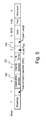
- Figure 5 shows the format of an Ethernet frame and the position of the destination address field 200 (6 bytes), source address field 202 (6 bytes) and VLAN tag field 204 (2 bytes).
Abstract
Description
- This invention relates to Ethernet switches and to a method of operating such a switch
- For many years now, telecommunications carriers have been deploying packet-switched networks in place of, or overlaid upon, circuit-switched networks for reasons of efficiency and economy. Packet-switched networks such as Internet Protocol (IP) or Ethernet networks are intrinsically connectionless in nature and, as a result, suffer from Quality of Service (QoS) problems. Customers value services which are guaranteed in terms of bandwidth and QoS.
- It is desired to use Ethernet switches in carriers' networks. Use of Ethernet switches in carriers' networks would have the advantages of interoperability, since mappings between Ethernet and other frame/packet/cell data structures such as IP, Frame Relay are well known, and economy, since Ethernet switches are relatively inexpensive compared to IP routers, for example. It would also provide a distinct advantage of being the principal technology used by enterprises that require a wide area network service from a carrier and therefore able to work in a native mode.
- A conventional high-capacity Ethernet switch has a set of input ports and a set of output ports which are connected via a switch fabric. On start-up, or on re-start, a conventional switched Ethernet network behaves like a 'classic' Ethernet Local Area Network (LAN) in that every Ethernet frame is broadcast across the entire network. Every switch, upon receiving an Ethernet frame on one port, broadcasts the frame out on every other port. The process repeats as the frame is received by other switches, thus broadcasting the frame across the entire network. In switched Ethernet networks Medium Access Control (MAC) address auto-learning functionality is provided to improve configuration efficiency. Ethernet frames have source and destination MAC addresses corresponding to their source and destination Ethernet ports. When an Ethernet frame sent out by a source switch is received by an intermediate or destination Ethernet switch the receiving switch observes the port on which the frame was received and the source address of the frame. The switch then builds a forwarding table for use in future frame switching. Once a MAC address has been seen on a port, that information is made available to all ports to be used if any encounters that address. A central processor builds a single Forwarding Database (FDB) on the basis of MAC addresses seen on all ports. Over time, the network builds up forwarding state enabling efficient switching of Ethernet frames, without relying on broadcast any further. On modem high-performance switches the FDB is typically replicated into a memory located at each input port, and the copy of the FDB associated with each port is the same. This allows each port to route a received frame without waiting to access a shared Forwarding Database. The overall memory requirement becomes significant in situations where the switch has a large number of input and output ports and a large FDB.
- Conventional Ethernet networks are connectionless, i.e. no path through the network is pre-established for a frame, or group of frames, corresponding to a traffic flow. Patent Application
PCT/GB2005/001332, filed 6 April 2005 - An Ethernet switch for use in an Ethernet network comprises a set of ingress ports for receiving data frames and a set of egress ports. A memory is associated with each ingress port and stores forwarding information indicating one or more of the egress ports to which data frames received by that ingress port should be forwarded. A control or management interface receives information about a network connection established, or to be established, through the switch. A switch controller causes forwarding information to be stored in a memory associated with a first ingress port which the network connection will use, on the basis of the received information about a network connection. Forwarding information is not stored in a memory associated with a second of the set of ingress ports which the network connection will not use. Preferably, the switch controller causes forwarding information to be stored only in a memory associated with the one or more ingress ports which the network connection will use and not to be stored in a memory associated with any of the other ingress ports. When traffic diverges (splits) at the Ethernet switch, forwarding information will cause a data frame arriving at an ingress port to be forwarded to multiple egress ports. When traffic routes converge at the Ethernet switch, forwarding information will be stored at each of the multiple ingress ports where data frames of those routes will arrive, and the forwarding information will cause the data frames to be forwarded to a common egress port.
- A consequence of using Ethernet switches in a connection-oriented mode of operation is that frames associated with a particular routing across the network will leave a switch by a known port and can only arrive at the switch through a known port (or set of ports). The Forwarding Database (FDB) associated with each ingress port may therefore be individually populated, and contain only those entries which the Network Management System knows could be validly received on that port. This allows a considerable reduction in FDB memory compared to replicating the FDB table to all ports in the manner of a conventional Ethernet switch, which allows a considerable cost saving. Alternatively, the network can be scaled for a given memory size. Investigation of typical carrier deployment scenarios shows that the reduction in memory size can easily be a factor of four.
- Although the ingress and egress ports have been separately referred to it will be understood that typically an Ethernet switch comprises a set of bi-directional interface ports, each bi-directional interface port comprising an ingress port and an egress port. The switch fabric selectively interconnects the ingress port of one bi-directional interface port with the egress port of another bi-directional interface port. Normally the ingress port and egress port of a bi-directional interface port will share a common MAC address.
- A further aspect of the invention provides a port card comprising an ingress port for receiving data frames and a memory for storing forwarding information indicating one or more egress ports of the switch to which data frames received by the ingress port should be forwarded. The forwarding information stored in the memory relates only to network connections which use that ingress port. The port card typically supports a bi-directional port having an ingress port function and an egress port function. The port card may house a single ingress port (or bi-directional port) or multiple ports (or bi-directional ports). The plurality of ingress ports may share the same memory.
- A further aspect of the invention provides a port controller comprising control logic which is operable to receive forwarding information from the switch controller for a network connection which is established, or will be established, via the ingress port and update the forwarding information in the memory for that ingress port. The forwarding information is received on the basis of whether the network connection will use that ingress port.
- A still further aspect of the invention provides a switch controller comprising control logic which is operable to receive information about a network connection established, or to be established, through the switch; and cause forwarding information to be stored in a memory associated with a first ingress port which the network connection will use, on the basis of the received information about a network connection, and not to be stored in a memory associated with a second ingress port which the network connection will not use.
- This functionality can be implemented in software, hardware or a combination of these. The invention can be implemented by means of hardware comprising several distinct elements, and by means of a suitably programmed computer. Accordingly, another aspect of the invention provides software for providing the functions of the switch controller and/or port controller. The software may be stored on an electronic memory device, hard disk, optical disk or other machine-readable storage medium. The software may be delivered as a computer program product on a machine-readable carrier or it may be downloaded directly to the switch via a network connection.
- Embodiments of the invention will be described, by way of example only, with reference to the accompanying drawings in which:
- Figure 1 shows an arrangement of Ethernet switches forming a carrier network and a connection across the carrier network;
- Figure 2 shows how nodes of the control plane interact with Ethernet switches of the transport plane to establish the connection shown in Figure 1;
- Figure 3 shows the use of differential forwarding for two traffic flows across a network;
- Figure 4 shows one of the Ethernet switches used in the network of Figures 1 and 2;
- Figure 5 shows the format of an Ethernet frame with VLAN tagging.
- Figures 1 and 2 show an arrangement of Ethernet switches and communications links forming a carrier network.
Carrier network cloud 20 comprisesEthernet switches Ethernet switches carrier network 20, whereas Ethernet switches 24a, 24b, and 28 are located in the core network. Communications links (shown as straight lines) are provided betweenEthernet switches core network switches core network switch - The
carrier Ethernet network 20 provides connectivity between customer sites. Three customers having respective pairs of geographically distant Ethernet switches (40a and 40b, 42a and 42b, 44a and 44b) are shown connected tocarrier network 20 viaedge Ethernet switches edge switches customer switches Carrier edge switches carrier network 20. The PE-Core preferentially encapsulates incoming Ethernet traffic from the customer using Media Access Control (MAC) in MAC encapsulation (or, if desired, Pseudo-Wire over MAC encapsulation) and forwards the encapsulated traffic across thecarrier network 20. This embodiment is preferred as a mechanism to limit the number of table entries required because only the MAC address space of the carrier network need be recognised, and not the whole of the customer's MAC address space, which could be changed independently. Similarly, the PE-Core decapsulates (strips) outgoing Ethernet traffic and forwards the stripped traffic on to the customer via the appropriate PE-Edge. VLAN tags are often used to provide customer separation at the logical PE-Core with each different customer site connected to each edge switch having a unique VLAN tag. Stacked VLAN (i.e. VLAN-in-VLAN encapsulation or Q-in-Q) may be used to protect any VLAN tags used by the customer traffic. For example,customer switch 42a may send Ethernet traffic over communications link 46a to the logical PE-Edge ofedge switch 22a. Logical PE-Core ofedge switch 22a encapsulates each Ethernet frame in a further Ethernet frame using the MAC address of the ingress port onedge switch 22a as the source address and the MAC address of the appropriate egress point - in this case a port onedge switch 22b - as the destination address. The encapsulated traffic is forwarded across a connection established overcommunications links 48 ofcarrier network 20 to edgeswitch 22b. Connections may be typically trunked in the sense that traffic from multiple customers will be routed through the same connection. Alternatively, those skilled in the art will appreciate thatseparate connections 48 could be used for each customer. At the PE-Core ofedge switch 22b, the original frames are stripped of their encapsulation and sent over communications link 46b via PE-Edge ofedge switch 22b to customer switch 42b. - The logical PE-Edge may also be physically separated from the logical PE-Core and may reside at customer premises whereas the PE-Core would preferentially reside at a central office or Point of Presence (PoP) of the carrier. The reader will also appreciate that other edge switches may also have connections to customer sites and that customers may have to be provided with connectivity between two or more geographically distant sites over
carrier network 20. - It will now be described how
carrier network 20 is arranged to establish connections through which to forward encapsulated Ethernet traffic. A connection may be defined as an entity configured in a network which provides transport of data from a source node to one or more sink nodes. As described above,carrier network 20 may be at least partially-meshed - i.e. there will usually be more than one possible path between at least some, and preferably all, nodes of the network. Thus, as will be explained below, broadcast and Ethernet MAC address auto learning functionality should be at least partially deactivated to permit loops to be formed safely in the network. On start-up (or on re-start), conventional switched Ethernet networks behave like a "classic" Ethernet Local Area Networks (LANs) in that every Ethernet frame is broadcast across the entire network. Thus, every switch, receiving an Ethernet frame on one port, broadcasts the frame out on every other port. The process repeats as the frame is received by other switches thus broadcasting the frame across the entire network. - MAC address auto-learning functionality is provided to improve configuration efficiency in switched Ethernet networks. Ethernet frames have source and destination MAC addresses corresponding to their source and destination Ethernet ports. (An Ethernet port here is signifying an end system which is therefore configured with at least one MAC address.) When an Ethernet frame sent out by a source switch is received by an intermediate or destination Ethernet switch, the receiving switch observes the port on which the frame was received and the source address of the frame. It then builds up a forwarding table for use in future frame switching. The forwarding table maps destination address to output port and is built up using the source address of a received frame and the input port on which it was received. Over time, the network builds up forwarding state enabling efficient switching of Ethernet frames, without relying on broadcast any further. It can thus be seen that conventional switched Ethernet networks using auto-learning must be simply-connected - i.e. there must be one and only one path between each and every node of the network. If there were multiple paths between any two nodes, the input port on which a frame is received from a source node would not be a reliable indicator of the correct output port to forward future traffic destined for that node. Inconsistencies in forwarding tables on Ethernet switches could result in looping of frames. Moreover, if there exists any loop in a part of the network then any broadcast packet will be continuously duplicated in that loop and the duplicates forwarded all over the whole network, limited only by the link capacities concerned. This inevitably results in catastrophic failure of the network.
- In a connection-oriented Ethernet network Ethernet switches do not use auto learning to independently configure their forwarding tables but, instead, forwarding tables are directly configured using an Ethernet control plane. In one possible embodiment this control plane may actually be a centralized Network Management system, with complete knowledge of the state of the entire network. In another embodiment, the control plane may be a distributed function. The configuration of such an Ethernet network will now be described with reference to the latter. Figure 2 shows
elements connection controllers Ethernet switches carrier network 20. Control Plane 30 may be conceptually thought of as lying 'above'transport plane 32 which comprises the Ethernet switches 22a, 22b, 24a, 24b, 26 and 28 ofcarrier network 20. Connection controllers (CCs) are logical agents each corresponding to a respective Ethernet switch (which represent cross connects in ASTN terminology) intransport plane 32. Each CC controls the switching of its respective switch using Connection Control Interface (CCI) signalling (shown as dotted lines in Figure 2). CCI signalling is used to directly configure the forwarding tables used byEthernet switches carrier network 20. CCs may communicate between themselves using a Network to Network Interface (NNI). Typically, CCs will exchange information regarding their operational state and the state, in particular the capacity, of their communications links using NNI signalling. Other control plane functions such as heartbeat, ping and circuit monitoring may be provided using the ITU-T standard-in-preparation currently referred to as Y.17ethOAM or the methods in IEEE standard 802.lag. - While
CCs Ethernet switches - Figure 2 shows how control plane 30 interacts with
transport plane 32 to establish a point-to-point connection acrosscarrier network 20. Typically, the connection will be bi-directional, although this can simply be considered as the combination of two unidirectional point to point connections. A request to establish a connection specifying a required bandwidth and an explicit route acrosscarrier network 20 is generated for example by a supervisory network management node (not shown) or distributed network management system or function. The explicit route will have been determined in accordance with a conventional routing protocol taking into account the topology of the carrier network, the operational state of network resources and the bandwidth requirements of existing and possible future connections. The route to be taken by the exemplary connection shown in Figure 2 spansEthernet switches CC 32a. On receipt of the request,CC 32a checks whether the communications link betweenswitches setup request message 50 to CC 34a specifying the required bandwidth and explicit route. CC 34a then checks whether the communications link betweenswitches setup message request 50reaches CC 32b. Along the route, CCs may optionally reserve bandwidth of their respective switches and communication links so as to avoid race conditions where competing connections are setup over the same resources. When connectionsetup request message 50reaches CC 32b, if there is sufficient bandwidth along the entire path to support the required connection, thenCC 32b sends a connectionsetup response message 52 back to CC 34b, CC 34a and finally toCC 32a. As the connectionsetup response message 52 traverses the CCs, each CC sends CCI signalling 54 to its respective switch to configure the forwarding tables of each switch, thereby to establish the forwarding state required to setup the connection. - It will be appreciated that the mechanism for establishing connections across
carrier network 20 described above is merely exemplary and other well-known mechanisms may be used. For example, all the admission control may be performed in a centralised CC controlling several if not all the Ethernet switches in the extreme. In another example arrangement, the supervisory management function may be used to compute routes for connections and simultaneously perform the necessary admission control; this in turn would simplify the role performed by the CC. Yet another example is where the supervisory management function or CC consults a specialised and either centralised or distributed Bandwidth Manager or Policy Decision Function to perform the admission control. - Typically, there will be many thousands or tens of thousands of connections established across a carrier network at any time. These connections will share the physical resources of the carrier network - i.e. the switches and communications links. Thus, each switch will typically have a large number of connections established through it at any point in time. However, each switch must be able to forward data traffic according to the explicit route requirements of the specific connection through which that traffic is being sent. A likely scenario is that the carrier network will need to establish multiple connections from the same source nodes, multiple connections to the same destination nodes and multiple connections both from the same source nodes and to the same destination nodes. However, for traffic engineering purposes, the latter connections may need to be established through physically distinct routes across the network. Furthermore, these routes may need to converge and diverge again within the carrier network. To support such route flexibility in connections, what is required is that each switch be able to differentiate between data traffic travelling in different connections and forward accordingly. A conventional switched Ethernet is incapable of differentiating between flows in this way since conventional Ethernet switches forward traffic based solely on a forwarding table (established through auto learning) mapping destination address to output port. As a result, a conventional Ethernet switch will not be able to differentiate between data traffic having the same destination address, although it may be associated with multiple different connections.
- There are various ways in which an Ethernet switch can be configured to recognise traffic belonging to certain intended paths across the network. A preferred way, described in unpublished Patent Application
PCT/GB2005/001332, filed 6 April 2005 Ethernet network 20 is allocated a unique combination of VLAN tag and destination address. Each Ethernet switch stores separate forwarding tables for each VLAN tag configured, the VLAN tag acting as a mapping (or indexing) to forwarding tables, and each forwarding table mapping destination address to output port. The group of forwarding tables at each switch provide a mapping from a combination of destination address and VLAN tag to output port. - According to the preferred embodiment, VLAN tags have meaning only within the context of a destination address. As such, the allocation of VLAN tags is logically localised to the node owning the destination address, herein called the destination node. Thus, at the point where a new connection is requested, its destination node will allocate to that connection a VLAN tag to use in combination with a destination address corresponding to that node. This VLAN tag will be allocated such that no existing connection to the destination address whose route crosses with & subsequently diverges from the new connection shall share a VLAN tag. This is such that where differential forwarding is required (at the divergence point), the destination address/VLAN tag pair of the diverging connections are distinct. Additional constraints can be placed on the allocation as described elsewhere to improve pathological behaviour in case of inadvertent partial route removal in a network where broadcast-on-unknown is not fully disabled on all VLAN tags used for connections.
- Figure 3 shows a way in which this behaviour can be used to route traffic within a network.
Connections 76 and 77 have both the same source address (edge Ethernet switch 71 - PE1) and destination address (edge Ethernet switch 73 - PE3). However, the routes thatconnections 76 and 77 traverse are different. In particular, it can be seen that atcore Ethernet switch 75,connections 76 and 77 converge and then immediately diverge. Despite the common destination address,core Ethernet switch 75 is able to differentiate frames belonging to connection 76 from frames belonging to connection 77 (and to forward them accordingly) on the basis of their different VLAN tags. Thus, data traffic in connection 76 has theVLAN tag 2, for example, whereas data traffic inconnection 77 has theVLAN tag 1. Differentiation between Ethernet frames belonging to different connections is achieved according to the combination of destination address and VLAN tag. A difference in either may be used to achieve differential forwarding required for connections. - Figure 4 schematically shows an Ethernet switch 100 according to an embodiment of the invention. The switch 100 has a set of ports 110-117 which are interconnected by a
switch fabric 140. Onesuch port 110 is shown in detail and each port has the same structure. Ethernet ports are bi-directional and comprise aningress section 120 and anegress section 130 which share a common MAC address. Theingress section 120 has aline interface 124 which connects to acommunication link 127. The line interface converts the incoming signal from a format used on theline 127 to a baseband electrical digital signal which can be used by the following stages. Typically, this involves receiving, and demodulating, an optical signal and decoding the demodulated signal from a line code used for transmission. For each frame,stage 125 determines a destination port of the switch that the frame should be sent to by examining fields within the frame and a priority for that frame. In the preferred scheme just described, this requiresstage 125 to inspect the destination address field and the VLAN tag field of the frame. A look-up table 123 is stored in amemory 122 local to the port.Stage 125 performs a look-up operation using the destination address and VLAN tag to identify the port that the frame should be sent to.Stage 125 sends the frame to theappropriate buffer 126 where the frame is queued before the switch fabric transfers the frame to the required destination port. Typically, a switch will transfer fixed sized blocks of data across the switch fabric (e.g. cells 80 bytes in length) to maximise efficiency of the switch and to minimise blocking between switch ports, but this is not important to the invention and the switch can use any technology for the switch fabric. At the egress section of the destination port the blocks are reassembled in abuffer 131 before being sent to aline interface 134. Typically, this will involve encoding the data frame with a line code and modulating the electrical digital signal onto an optical carrier. - Each port is associated with a
port controller 121 which is responsible for maintaining the forwarding table 123 at that port.Port controller 121 communicates with aswitch controller 102.Port controller 121 is essentially a 'housekeeping' processor which performs tasks locally at the port, in response to instructions received fromswitch controller 102.Switch controller 102 maintains a master forwarding table 104 instorage 103 local to thecontroller 102 and communicates via asignalling interface 105 to a connection controller. As connections acrossnetwork 20 are set-up, changed (e.g. due to traffic management operations) or torn down,switch controller 102 receives instructions to add or remove entries in the forwarding table 104 from a network connection controller. The information received atswitch controller 102 from a Network Management System will typically refer to a physical address and will set up a bi-directional path (i.e. forward and return paths) at the same time {i.e. forward frames with destination MAC_address1 and VLAN1 arriving at port X to port Y; forward return-path frames with destination MAC_address2 and VLAN2 arriving at port Y to port X}. Alternatively, theswitch controller 102 may receive information in the form of a more symbolic address which is resolved to a physical address at switch 100 (e.g. to determine the exact ports involved in the connection). For each change to table 104,switch controller 102 determines which port is affected by the change and then instructs the port controller responsible for that port of the change.Port controller 121 then updates the forwarding table 123 held locally at the port. It can be seen that because each port only maintains a forwarding table of connections involving that port, the size of the local table is much smaller than would otherwise be needed. This allows the port to have a smaller memory, which reduces cost of each port. The association between aport controller 121/memory 122 and a port can be 1:1 (i.e. oneport controller 121 andmemory 122 for each bi-directional port, which allows highspeed access to forwarding table 123 held within memory 122) or it can be 1:N where N is the set of ports on a port card or a sub-set of the ports. - As an example of the type of forwarding table held at each port, the following represents part of the forwarding table 123 held at port 110:
Destination Address VLAN tag Destination port Node 22b 1 Port 117Node 22b2 Port 114Node 22c 1 Port 115Node 22c 3 Port 116Node 22b or Node 22c. In this example, a frame arriving atport 110 with a destination address field set to 'Node 22b' and a VLAN tag =1 would be routed todestination port 117 of the switch, as shown bypath 141 of Figure 4. Because a connection controller controls a path acrossnetwork 20, it is known which switches each traffic flow will pass through, and at which port the traffic flow will arrive and leave. Although each entry in the above forwarding table lists only one destination port, it is possible to forward data frames to multiple destination ports. Table 123 does not need to store forwarding information for any traffic flows which do not arrive atport 110. Traffic will often involve a reverse flow, which is shown aspath 142 acrossswitch fabric 140. Frames arriving atingress section 150 ofport 117 will be routed to theegress section 130 ofport 110 using look-up table 153. In the case where traffic flows merge at switch, the same forwarding information will be stored in forwarding tables 123 associated with multiple of theingress ports 120. - In the embodiment described above each port has a
port controller 121. However, it is not essential that a port controller is provided for each port. Where a switch provides multiple physical ports per peripheral card, each card can have a port/card controller - essentially a 'housekeeping' processor - which talks to the hardware and communicates with the switch controller. The switch controller can specify exactly which port is to be updated by the port/card controller. - For completeness, Figure 5 shows the format of an Ethernet frame and the position of the destination address field 200 (6 bytes), source address field 202 (6 bytes) and VLAN tag field 204 (2 bytes).
- The invention is not limited to the embodiments described herein, which may be modified or varied without departing from the scope of the invention.
Claims (17)
- An Ethernet switch for use in an Ethernet network, the switch comprising:a set of ingress ports for receiving data frames;a set of egress ports;a switch fabric for selectively interconnecting the ingress and egress ports;a memory, associated with each ingress port, for storing forwarding information indicating one or more of the egress ports to which data frames received by that ingress port should be forwarded;a control or management interface for receiving information about a network connection established, or to be established, through the switch; anda switch controller which is arranged to cause forwarding information to be stored in a memory associated with a first ingress port which the network connection will use, on the basis of the received information about a network connection, and not to be stored in a memory associated with a second ingress port which the network connection will not use.
- An Ethernet switch according to claim 1 wherein the switch controller is arranged to cause forwarding information to be stored only in a memory associated with the first ingress port which the network connection will use, on the basis of the received information about a network connection.
- An Ethernet switch according to claim 1 wherein the forwarding information stored in a memory comprises a destination network address and a VLAN tag, or part thereof, of a data frame expected to be received at that ingress port and one or more egress ports to which the data frame should be forwarded.
- An Ethernet switch according to claim 1 wherein the information comprises a destination network address and at least one of: an IEEE 802.1Q field and an MPLS label, or part thereof, of a data frame expected to be received at that ingress port and one or more egress ports to which the data frame should be forwarded.
- An Ethernet switch according to claim 1 wherein each ingress port has a port controller and the port controller is arranged to receive the selected forwarding information and to update the forwarding information in the memory associated with that ingress port.
- An Ethernet network comprising a plurality of Ethernet switches according to claim 1.
- A port card for use in an Ethernet switch of an Ethernet network in which a network connection may be established through the switch, the switch comprising a set of port cards, each port card comprising:an ingress port for receiving data frames; anda memory for storing forwarding information indicating one or more egress ports of the switch to which data frames received by the ingress port should be forwarded;wherein the forwarding information stored in the memory relates only to network connections which use that ingress port.
- A port card according to claim 7 comprising a plurality of ingress ports.
- A port card according to claim 8 wherein the plurality of ingress ports share the same memory.
- A port controller for an ingress port of an Ethernet switch in an Ethernet network, the switch comprising a set of ingress ports for receiving data frames, a set of egress ports, a switch controller which is arranged to receive information about connections across the network, and wherein the ingress ports each have a memory for storing forwarding information indicating one or more of the egress ports to which data frames received by that port should be forwarded, the port controller comprising control logic which is operable to:receive forwarding information from the switch controller for a network connection which is established, or will be established, via the ingress port; andupdate the forwarding information in the memory for that ingress portwherein the forwarding information is received on the basis of whether the network connection will use that ingress port.
- An ingress port card comprising the port controller according to claim 10.
- A switch controller for an Ethernet switch in an Ethernet network, the switch comprising a set of ingress ports for receiving data frames and a set of egress ports, each ingress port having a memory associated with it for storing forwarding information indicating one or more of the egress ports to which data frames received by that ingress port should be forwarded, the switch controller comprising control logic which is operable to:receive information about a network connection established, or to be established, through the switch; andcause forwarding information to be stored in a memory associated with a first ingress port which the network connection will use, on the basis of the received information about a network connection, and not to be stored in a memory associated with a second ingress port which the network connection will not use.
- A switch according to claim 12 which is operable to cause forwarding information to only be stored in a memory associated with the first ingress port which the network connection will use on the basis of the received information about a network connection.
- A method of managing forwarding information at an ingress port of an Ethernet switch, the switch comprising a set of ingress ports for receiving data frames, a set of egress ports and a memory associated with each ingress port for storing forwarding information indicating one or more of the egress ports to which data frames received by that ingress port should be forwarded, the method comprising:receiving, via a control or management interface, information about a network connection established, or to be established, through the switch; andcausing forwarding information to be stored in a memory associated with a first ingress port which the network connection will use, on the basis of the received information about a network connection, and not to be stored in a memory associated with a second ingress port which the network connection will not use.
- A method according to claim 14 which is operable to cause forwarding information to be stored only in a memory associated with the first ingress port which the network connection will use on the basis of the received information about a network connection.
- Instructions for causing a processor at an Ethernet switch to perform the method according to claim 14.
- A machine-readable medium carrying the instructions of claim 16.
Applications Claiming Priority (1)
| Application Number | Priority Date | Filing Date | Title |
|---|---|---|---|
| US11/223,246 US8498297B2 (en) | 2005-08-26 | 2005-08-26 | Forwarding table minimisation in ethernet switches |
Publications (2)
| Publication Number | Publication Date |
|---|---|
| EP1758320A1 true EP1758320A1 (en) | 2007-02-28 |
| EP1758320B1 EP1758320B1 (en) | 2010-04-21 |
Family
ID=37036933
Family Applications (1)
| Application Number | Title | Priority Date | Filing Date |
|---|---|---|---|
| EP06076558A Not-in-force EP1758320B1 (en) | 2005-08-26 | 2006-08-10 | Forwarding table management in ethernet switch |
Country Status (5)
| Country | Link |
|---|---|
| US (2) | US8498297B2 (en) |
| EP (1) | EP1758320B1 (en) |
| CN (1) | CN101072162B (en) |
| AT (1) | ATE465578T1 (en) |
| DE (1) | DE602006013758D1 (en) |
Cited By (12)
| Publication number | Priority date | Publication date | Assignee | Title |
|---|---|---|---|---|
| EP2107733A1 (en) * | 2008-03-31 | 2009-10-07 | British Telecommunications Public Limited Company | Admission control and routing in a packet network |
| EP2107735A1 (en) * | 2008-03-31 | 2009-10-07 | British Telecmmunications public limited campany | Admission control in a packet network |
| GB2461955A (en) * | 2008-07-25 | 2010-01-27 | Gnodal Ltd | Ethernet bridge or router employing a distributed MAC address table |
| EP2211509A3 (en) * | 2009-01-27 | 2010-08-18 | Hitachi, Ltd. | Network communication node |
| EP2466826A1 (en) * | 2010-12-15 | 2012-06-20 | Juniper Networks, Inc. | Methods and apparatus for dynamic resource management within a distributed control plane of a switch |
| US8560660B2 (en) | 2010-12-15 | 2013-10-15 | Juniper Networks, Inc. | Methods and apparatus for managing next hop identifiers in a distributed switch fabric system |
| US8718063B2 (en) | 2010-07-26 | 2014-05-06 | Juniper Networks, Inc. | Methods and apparatus related to route selection within a network |
| US8798045B1 (en) | 2008-12-29 | 2014-08-05 | Juniper Networks, Inc. | Control plane architecture for switch fabrics |
| US9106527B1 (en) | 2010-12-22 | 2015-08-11 | Juniper Networks, Inc. | Hierarchical resource groups for providing segregated management access to a distributed switch |
| US9240923B2 (en) | 2010-03-23 | 2016-01-19 | Juniper Networks, Inc. | Methods and apparatus for automatically provisioning resources within a distributed control plane of a switch |
| US9391796B1 (en) | 2010-12-22 | 2016-07-12 | Juniper Networks, Inc. | Methods and apparatus for using border gateway protocol (BGP) for converged fibre channel (FC) control plane |
| US9531644B2 (en) | 2011-12-21 | 2016-12-27 | Juniper Networks, Inc. | Methods and apparatus for a distributed fibre channel control plane |
Families Citing this family (23)
| Publication number | Priority date | Publication date | Assignee | Title |
|---|---|---|---|---|
| US7929455B2 (en) * | 2006-12-20 | 2011-04-19 | Alcatel Lucent | Bridge and method for optimization of memory for Ethernet OAM multicast frames |
| JP4259581B2 (en) * | 2007-02-07 | 2009-04-30 | 日立電線株式会社 | Switching hub and LAN system |
| US8832755B2 (en) * | 2007-04-30 | 2014-09-09 | Ciena Corporation | Methods and systems for interactive video transport over Ethernet networks |
| JP5071200B2 (en) * | 2008-03-28 | 2012-11-14 | 富士通株式会社 | Signal transmission device |
| KR100994127B1 (en) | 2008-08-28 | 2010-11-15 | 한국전자통신연구원 | Packet processing method for improving Ethernet switch performance |
| KR101025674B1 (en) | 2010-02-03 | 2011-03-30 | 엘에스산전 주식회사 | Device for switching a dual port ethernet |
| JP2011249979A (en) * | 2010-05-25 | 2011-12-08 | Nec Corp | Communication system |
| US8897134B2 (en) * | 2010-06-25 | 2014-11-25 | Telefonaktiebolaget L M Ericsson (Publ) | Notifying a controller of a change to a packet forwarding configuration of a network element over a communication channel |
| US8787394B2 (en) | 2011-02-01 | 2014-07-22 | Ciena Corporation | Separate ethernet forwarding and control plane systems and methods with interior gateway route reflector for a link state routing system |
| US8717875B2 (en) * | 2011-04-15 | 2014-05-06 | Alcatel Lucent | Condensed core-energy-efficient architecture for WAN IP backbones |
| US9838319B2 (en) * | 2011-09-26 | 2017-12-05 | Wilmerding Communications Llc | Encapsulation system featuring an intelligent network component |
| US8891405B2 (en) * | 2012-07-18 | 2014-11-18 | International Business Machines Corporation | Integrated device management over Ethernet network |
| US9100216B2 (en) * | 2012-07-23 | 2015-08-04 | Cisco Technology, Inc. | System and method for scaling IPv6 on a three-tier network architecture at a large data center |
| CN102957591B (en) * | 2012-11-21 | 2015-05-27 | 烽火通信科技股份有限公司 | Implementation method of distributed VPLS (Virtual Private Lan Service) |
| CN102970621B (en) * | 2012-11-23 | 2015-09-16 | 中兴通讯股份有限公司 | Transmission resource management device and method in a kind of network element |
| CN104038425B (en) | 2013-03-06 | 2018-01-02 | 阿里巴巴集团控股有限公司 | The method and apparatus for forwarding ether network packet |
| US9660836B2 (en) * | 2014-05-06 | 2017-05-23 | Lattice Semiconductor Corporation | Network topology discovery |
| US9590825B2 (en) | 2014-05-09 | 2017-03-07 | Lattice Semiconductor Corporation | Stream creation with limited topology information |
| SG11201700004PA (en) * | 2014-07-03 | 2017-01-27 | Fiber Mountain Inc | Data center path switch with improved path interconnection architecture |
| US20190028409A1 (en) * | 2017-07-19 | 2019-01-24 | Alibaba Group Holding Limited | Virtual switch device and method |
| CN110401558B (en) * | 2019-04-28 | 2023-07-25 | 北京广利核系统工程有限公司 | Security level multi-point communication network equipment, system and security level network communication method |
| US11055254B2 (en) * | 2019-12-09 | 2021-07-06 | The Aerospace Corporation | Mixed media ethernet switch |
| CN111556102B (en) * | 2020-04-14 | 2023-02-28 | 深圳震有科技股份有限公司 | Data channel establishing method, ethernet switch and storage medium |
Citations (4)
| Publication number | Priority date | Publication date | Assignee | Title |
|---|---|---|---|---|
| EP0993156A2 (en) | 1998-10-05 | 2000-04-12 | Alcatel | Network switching device with forwarding database tables populated based on use |
| US20030152075A1 (en) | 2002-02-14 | 2003-08-14 | Hawthorne Austin J. | Virtual local area network identifier translation in a packet-based network |
| US20050141517A1 (en) | 2003-12-27 | 2005-06-30 | Choi Woo-Young | Packet forwarding apparatus of high speed routing system and routing lookup method using the same |
| WO2005099183A1 (en) | 2004-04-06 | 2005-10-20 | Nortel Networks Limited | Differential forwarding in address-based carrier networks |
Family Cites Families (28)
| Publication number | Priority date | Publication date | Assignee | Title |
|---|---|---|---|---|
| JP2856050B2 (en) * | 1993-11-30 | 1999-02-10 | 日本電気株式会社 | Routing control method |
| US5655140A (en) | 1994-07-22 | 1997-08-05 | Network Peripherals | Apparatus for translating frames of data transferred between heterogeneous local area networks |
| US5959990A (en) | 1996-03-12 | 1999-09-28 | Bay Networks, Inc. | VLAN frame format |
| US5764636A (en) * | 1996-03-28 | 1998-06-09 | Cisco Technology, Inc. | Color blocking logic mechanism for a high-performance network switch |
| US6108342A (en) | 1997-02-14 | 2000-08-22 | Advanced Micro Devices, Inc. | Management information base (MIB) accumulation processor |
| US6118760A (en) * | 1997-06-30 | 2000-09-12 | Sun Microsystems, Inc. | Management of entries in a network element forwarding memory |
| US6181699B1 (en) | 1998-07-01 | 2001-01-30 | National Semiconductor Corporation | Apparatus and method of assigning VLAN tags |
| US6563832B1 (en) | 1998-11-30 | 2003-05-13 | Cisco Technology, Inc. | Token ring bridge distributed in a switched fabric |
| US6515993B1 (en) | 1999-05-28 | 2003-02-04 | Advanced Micro Devices, Inc. | Method and apparatus for manipulating VLAN tags |
| US7075926B2 (en) | 2000-05-24 | 2006-07-11 | Alcatel Internetworking, Inc. (Pe) | Programmable packet processor with flow resolution logic |
| JP4168574B2 (en) * | 2000-06-02 | 2008-10-22 | 株式会社日立製作所 | Packet transfer apparatus, packet transfer control method, and packet transfer apparatus setting method |
| US7046680B1 (en) | 2000-11-28 | 2006-05-16 | Mci, Inc. | Network access system including a programmable access device having distributed service control |
| US6990106B2 (en) | 2001-03-19 | 2006-01-24 | Alcatel | Classification and tagging rules for switching nodes |
| JP4236398B2 (en) * | 2001-08-15 | 2009-03-11 | 富士通株式会社 | Communication method, communication system, and communication connection program |
| JP2003069570A (en) * | 2001-08-27 | 2003-03-07 | Allied Tereshisu Kk | Management system |
| WO2003027807A2 (en) | 2001-09-24 | 2003-04-03 | Rumi Sheryar Gonda | Method for supporting ethernet mac circuits |
| US7286533B2 (en) | 2001-12-27 | 2007-10-23 | Alcatel-Lucent Canada Inc. | Method and apparatus for routing data frames |
| US20030179755A1 (en) * | 2002-01-18 | 2003-09-25 | Fraser Alexander Gibson | System and method for handling prioritized data in a network |
| US7260097B2 (en) | 2002-01-30 | 2007-08-21 | Nortel Networks Limited | Label control method and apparatus for virtual private LAN segment networks |
| US7328284B2 (en) * | 2002-05-06 | 2008-02-05 | Qlogic, Corporation | Dynamic configuration of network data flow using a shared I/O subsystem |
| US20030214962A1 (en) | 2002-05-15 | 2003-11-20 | Mark Allaye-Chan | Method and apparatus for bandwidth optimization in network ring topology |
| US7180899B2 (en) * | 2002-10-29 | 2007-02-20 | Cisco Technology, Inc. | Multi-tiered Virtual Local area Network (VLAN) domain mapping mechanism |
| KR100480366B1 (en) | 2002-12-24 | 2005-03-31 | 한국전자통신연구원 | A system for VLAN configuration of E-PON and method thereof, its program stored recording medium |
| US7835367B2 (en) * | 2003-04-23 | 2010-11-16 | Fujitsu Limited | Network connection method, network connection system, and, layer 2 switch and management server forming the network connection system |
| US7301949B2 (en) * | 2003-07-15 | 2007-11-27 | Telefonaktiebolaget Lm Ericsson (Publ) | Arrangements for connection-oriented transport in a packet switched communications network |
| US7149214B2 (en) * | 2003-11-04 | 2006-12-12 | Cisco Technology, Inc. | Dynamic unknown L2 flooding control with MAC limits |
| US7672318B2 (en) * | 2003-11-06 | 2010-03-02 | Telefonaktiebolaget L M Ericsson (Publ) | Adaptable network bridge |
| BRPI0519612A2 (en) * | 2004-12-31 | 2009-02-25 | British Telecomm | switching apparatus in a communications network, methods of modifying switching apparatus positioned in a communications network, of switching packets via a communications network comprising a plurality of interconnected switching apparatus, of generating an end-to-end connection via a communications network comprising a plurality of switching apparatus preconfigured to support a connectionless communications protocol, to provide differentiated routing modes for packetized data, to configure switching apparatus to receive management and/or signaling information, network of communications, control plane processor, and, communication scheme to configure a network |
-
2005
- 2005-08-26 US US11/223,246 patent/US8498297B2/en not_active Expired - Fee Related
-
2006
- 2006-08-10 EP EP06076558A patent/EP1758320B1/en not_active Not-in-force
- 2006-08-10 AT AT06076558T patent/ATE465578T1/en not_active IP Right Cessation
- 2006-08-10 DE DE602006013758T patent/DE602006013758D1/en active Active
- 2006-08-25 CN CN2006101212718A patent/CN101072162B/en not_active Expired - Fee Related
-
2013
- 2013-06-24 US US13/925,196 patent/US20130287039A1/en not_active Abandoned
Patent Citations (4)
| Publication number | Priority date | Publication date | Assignee | Title |
|---|---|---|---|---|
| EP0993156A2 (en) | 1998-10-05 | 2000-04-12 | Alcatel | Network switching device with forwarding database tables populated based on use |
| US20030152075A1 (en) | 2002-02-14 | 2003-08-14 | Hawthorne Austin J. | Virtual local area network identifier translation in a packet-based network |
| US20050141517A1 (en) | 2003-12-27 | 2005-06-30 | Choi Woo-Young | Packet forwarding apparatus of high speed routing system and routing lookup method using the same |
| WO2005099183A1 (en) | 2004-04-06 | 2005-10-20 | Nortel Networks Limited | Differential forwarding in address-based carrier networks |
Cited By (24)
| Publication number | Priority date | Publication date | Assignee | Title |
|---|---|---|---|---|
| EP2107733A1 (en) * | 2008-03-31 | 2009-10-07 | British Telecommunications Public Limited Company | Admission control and routing in a packet network |
| EP2107735A1 (en) * | 2008-03-31 | 2009-10-07 | British Telecmmunications public limited campany | Admission control in a packet network |
| WO2009122150A1 (en) * | 2008-03-31 | 2009-10-08 | British Telecommunications Public Limited Company | Admission control in a packet network |
| WO2009122152A1 (en) * | 2008-03-31 | 2009-10-08 | British Telecommunications Public Limited Company | Admission control and routing in a packet network |
| US10355974B2 (en) | 2008-03-31 | 2019-07-16 | British Telecommunications Public Limited Company | Admission control in a packet network |
| GB2461955A (en) * | 2008-07-25 | 2010-01-27 | Gnodal Ltd | Ethernet bridge or router employing a distributed MAC address table |
| US8898431B2 (en) | 2008-07-25 | 2014-11-25 | Cray HK Limited | Multi-path network |
| US8798045B1 (en) | 2008-12-29 | 2014-08-05 | Juniper Networks, Inc. | Control plane architecture for switch fabrics |
| US8964733B1 (en) | 2008-12-29 | 2015-02-24 | Juniper Networks, Inc. | Control plane architecture for switch fabrics |
| EP2211509A3 (en) * | 2009-01-27 | 2010-08-18 | Hitachi, Ltd. | Network communication node |
| US9240923B2 (en) | 2010-03-23 | 2016-01-19 | Juniper Networks, Inc. | Methods and apparatus for automatically provisioning resources within a distributed control plane of a switch |
| US10645028B2 (en) | 2010-03-23 | 2020-05-05 | Juniper Networks, Inc. | Methods and apparatus for automatically provisioning resources within a distributed control plane of a switch |
| US8718063B2 (en) | 2010-07-26 | 2014-05-06 | Juniper Networks, Inc. | Methods and apparatus related to route selection within a network |
| EP2466826A1 (en) * | 2010-12-15 | 2012-06-20 | Juniper Networks, Inc. | Methods and apparatus for dynamic resource management within a distributed control plane of a switch |
| US8560660B2 (en) | 2010-12-15 | 2013-10-15 | Juniper Networks, Inc. | Methods and apparatus for managing next hop identifiers in a distributed switch fabric system |
| US9282060B2 (en) | 2010-12-15 | 2016-03-08 | Juniper Networks, Inc. | Methods and apparatus for dynamic resource management within a distributed control plane of a switch |
| US9106527B1 (en) | 2010-12-22 | 2015-08-11 | Juniper Networks, Inc. | Hierarchical resource groups for providing segregated management access to a distributed switch |
| US9954732B1 (en) | 2010-12-22 | 2018-04-24 | Juniper Networks, Inc. | Hierarchical resource groups for providing segregated management access to a distributed switch |
| US9391796B1 (en) | 2010-12-22 | 2016-07-12 | Juniper Networks, Inc. | Methods and apparatus for using border gateway protocol (BGP) for converged fibre channel (FC) control plane |
| US10868716B1 (en) | 2010-12-22 | 2020-12-15 | Juniper Networks, Inc. | Hierarchical resource groups for providing segregated management access to a distributed switch |
| US9565159B2 (en) | 2011-12-21 | 2017-02-07 | Juniper Networks, Inc. | Methods and apparatus for a distributed fibre channel control plane |
| US9819614B2 (en) | 2011-12-21 | 2017-11-14 | Juniper Networks, Inc. | Methods and apparatus for a distributed fibre channel control plane |
| US9992137B2 (en) | 2011-12-21 | 2018-06-05 | Juniper Networks, Inc. | Methods and apparatus for a distributed Fibre Channel control plane |
| US9531644B2 (en) | 2011-12-21 | 2016-12-27 | Juniper Networks, Inc. | Methods and apparatus for a distributed fibre channel control plane |
Also Published As
| Publication number | Publication date |
|---|---|
| ATE465578T1 (en) | 2010-05-15 |
| US8498297B2 (en) | 2013-07-30 |
| DE602006013758D1 (en) | 2010-06-02 |
| CN101072162B (en) | 2011-03-30 |
| US20130287039A1 (en) | 2013-10-31 |
| CN101072162A (en) | 2007-11-14 |
| US20070047540A1 (en) | 2007-03-01 |
| EP1758320B1 (en) | 2010-04-21 |
Similar Documents
| Publication | Publication Date | Title |
|---|---|---|
| EP1758320B1 (en) | Forwarding table management in ethernet switch | |
| US8855020B2 (en) | Automatically maximizing network link utilization using virtual networks | |
| JP5106100B2 (en) | Differential transfer in addressed carrier networks | |
| US6934292B1 (en) | Method and system for emulating a single router in a switch stack | |
| JP3714238B2 (en) | Network transfer system and transfer method | |
| US8923292B2 (en) | Differential forwarding in address-based carrier networks | |
| US9231890B2 (en) | Traffic management for virtual cluster switching | |
| US8797843B2 (en) | High availability distributed fabric protocol (DFP) switching network architecture | |
| US20110299551A1 (en) | Method and Apparatus for Transferring Data Packets Between a First Network and a Second Network | |
| US7881307B2 (en) | Multiple-instance meshing | |
| Iwata et al. | Global open Ethernet architecture for a cost-effective scalable VPN solution | |
| CA2573495C (en) | Automatically maximizing network link utilization using virtual networks | |
| GB2438767A (en) | Identifying packets for forwarding through connections |
Legal Events
| Date | Code | Title | Description |
|---|---|---|---|
| PUAI | Public reference made under article 153(3) epc to a published international application that has entered the european phase |
Free format text: ORIGINAL CODE: 0009012 |
|
| AK | Designated contracting states |
Kind code of ref document: A1 Designated state(s): AT BE BG CH CY CZ DE DK EE ES FI FR GB GR HU IE IS IT LI LT LU LV MC NL PL PT RO SE SI SK TR |
|
| AX | Request for extension of the european patent |
Extension state: AL BA HR MK YU |
|
| 17P | Request for examination filed |
Effective date: 20070828 |
|
| 17Q | First examination report despatched |
Effective date: 20070926 |
|
| AKX | Designation fees paid |
Designated state(s): AT BE BG CH CY CZ DE DK EE ES FI FR GB GR HU IE IS IT LI LT LU LV MC NL PL PT RO SE SI SK TR |
|
| GRAP | Despatch of communication of intention to grant a patent |
Free format text: ORIGINAL CODE: EPIDOSNIGR1 |
|
| GRAS | Grant fee paid |
Free format text: ORIGINAL CODE: EPIDOSNIGR3 |
|
| GRAA | (expected) grant |
Free format text: ORIGINAL CODE: 0009210 |
|
| AK | Designated contracting states |
Kind code of ref document: B1 Designated state(s): AT BE BG CH CY CZ DE DK EE ES FI FR GB GR HU IE IS IT LI LT LU LV MC NL PL PT RO SE SI SK TR |
|
| REG | Reference to a national code |
Ref country code: GB Ref legal event code: FG4D |
|
| REG | Reference to a national code |
Ref country code: CH Ref legal event code: EP |
|
| REG | Reference to a national code |
Ref country code: IE Ref legal event code: FG4D |
|
| REF | Corresponds to: |
Ref document number: 602006013758 Country of ref document: DE Date of ref document: 20100602 Kind code of ref document: P |
|
| REG | Reference to a national code |
Ref country code: NL Ref legal event code: VDEP Effective date: 20100421 |
|
| LTIE | Lt: invalidation of european patent or patent extension |
Effective date: 20100421 |
|
| PG25 | Lapsed in a contracting state [announced via postgrant information from national office to epo] |
Ref country code: LT Free format text: LAPSE BECAUSE OF FAILURE TO SUBMIT A TRANSLATION OF THE DESCRIPTION OR TO PAY THE FEE WITHIN THE PRESCRIBED TIME-LIMIT Effective date: 20100421 Ref country code: ES Free format text: LAPSE BECAUSE OF FAILURE TO SUBMIT A TRANSLATION OF THE DESCRIPTION OR TO PAY THE FEE WITHIN THE PRESCRIBED TIME-LIMIT Effective date: 20100801 Ref country code: SE Free format text: LAPSE BECAUSE OF FAILURE TO SUBMIT A TRANSLATION OF THE DESCRIPTION OR TO PAY THE FEE WITHIN THE PRESCRIBED TIME-LIMIT Effective date: 20100421 Ref country code: NL Free format text: LAPSE BECAUSE OF FAILURE TO SUBMIT A TRANSLATION OF THE DESCRIPTION OR TO PAY THE FEE WITHIN THE PRESCRIBED TIME-LIMIT Effective date: 20100421 |
|
| PG25 | Lapsed in a contracting state [announced via postgrant information from national office to epo] |
Ref country code: IS Free format text: LAPSE BECAUSE OF FAILURE TO SUBMIT A TRANSLATION OF THE DESCRIPTION OR TO PAY THE FEE WITHIN THE PRESCRIBED TIME-LIMIT Effective date: 20100821 Ref country code: LV Free format text: LAPSE BECAUSE OF FAILURE TO SUBMIT A TRANSLATION OF THE DESCRIPTION OR TO PAY THE FEE WITHIN THE PRESCRIBED TIME-LIMIT Effective date: 20100421 Ref country code: AT Free format text: LAPSE BECAUSE OF FAILURE TO SUBMIT A TRANSLATION OF THE DESCRIPTION OR TO PAY THE FEE WITHIN THE PRESCRIBED TIME-LIMIT Effective date: 20100421 Ref country code: FI Free format text: LAPSE BECAUSE OF FAILURE TO SUBMIT A TRANSLATION OF THE DESCRIPTION OR TO PAY THE FEE WITHIN THE PRESCRIBED TIME-LIMIT Effective date: 20100421 Ref country code: SI Free format text: LAPSE BECAUSE OF FAILURE TO SUBMIT A TRANSLATION OF THE DESCRIPTION OR TO PAY THE FEE WITHIN THE PRESCRIBED TIME-LIMIT Effective date: 20100421 |
|
| PG25 | Lapsed in a contracting state [announced via postgrant information from national office to epo] |
Ref country code: PL Free format text: LAPSE BECAUSE OF FAILURE TO SUBMIT A TRANSLATION OF THE DESCRIPTION OR TO PAY THE FEE WITHIN THE PRESCRIBED TIME-LIMIT Effective date: 20100421 Ref country code: GR Free format text: LAPSE BECAUSE OF FAILURE TO SUBMIT A TRANSLATION OF THE DESCRIPTION OR TO PAY THE FEE WITHIN THE PRESCRIBED TIME-LIMIT Effective date: 20100722 Ref country code: CY Free format text: LAPSE BECAUSE OF FAILURE TO SUBMIT A TRANSLATION OF THE DESCRIPTION OR TO PAY THE FEE WITHIN THE PRESCRIBED TIME-LIMIT Effective date: 20100505 |
|
| PG25 | Lapsed in a contracting state [announced via postgrant information from national office to epo] |
Ref country code: PT Free format text: LAPSE BECAUSE OF FAILURE TO SUBMIT A TRANSLATION OF THE DESCRIPTION OR TO PAY THE FEE WITHIN THE PRESCRIBED TIME-LIMIT Effective date: 20100823 Ref country code: EE Free format text: LAPSE BECAUSE OF FAILURE TO SUBMIT A TRANSLATION OF THE DESCRIPTION OR TO PAY THE FEE WITHIN THE PRESCRIBED TIME-LIMIT Effective date: 20100421 Ref country code: DK Free format text: LAPSE BECAUSE OF FAILURE TO SUBMIT A TRANSLATION OF THE DESCRIPTION OR TO PAY THE FEE WITHIN THE PRESCRIBED TIME-LIMIT Effective date: 20100421 |
|
| PLBE | No opposition filed within time limit |
Free format text: ORIGINAL CODE: 0009261 |
|
| STAA | Information on the status of an ep patent application or granted ep patent |
Free format text: STATUS: NO OPPOSITION FILED WITHIN TIME LIMIT |
|
| PG25 | Lapsed in a contracting state [announced via postgrant information from national office to epo] |
Ref country code: CZ Free format text: LAPSE BECAUSE OF FAILURE TO SUBMIT A TRANSLATION OF THE DESCRIPTION OR TO PAY THE FEE WITHIN THE PRESCRIBED TIME-LIMIT Effective date: 20100421 Ref country code: BE Free format text: LAPSE BECAUSE OF FAILURE TO SUBMIT A TRANSLATION OF THE DESCRIPTION OR TO PAY THE FEE WITHIN THE PRESCRIBED TIME-LIMIT Effective date: 20100421 Ref country code: SK Free format text: LAPSE BECAUSE OF FAILURE TO SUBMIT A TRANSLATION OF THE DESCRIPTION OR TO PAY THE FEE WITHIN THE PRESCRIBED TIME-LIMIT Effective date: 20100421 Ref country code: RO Free format text: LAPSE BECAUSE OF FAILURE TO SUBMIT A TRANSLATION OF THE DESCRIPTION OR TO PAY THE FEE WITHIN THE PRESCRIBED TIME-LIMIT Effective date: 20100421 |
|
| 26N | No opposition filed |
Effective date: 20110124 |
|
| PG25 | Lapsed in a contracting state [announced via postgrant information from national office to epo] |
Ref country code: MC Free format text: LAPSE BECAUSE OF NON-PAYMENT OF DUE FEES Effective date: 20100831 Ref country code: IT Free format text: LAPSE BECAUSE OF FAILURE TO SUBMIT A TRANSLATION OF THE DESCRIPTION OR TO PAY THE FEE WITHIN THE PRESCRIBED TIME-LIMIT Effective date: 20100421 |
|
| REG | Reference to a national code |
Ref country code: CH Ref legal event code: PL |
|
| PG25 | Lapsed in a contracting state [announced via postgrant information from national office to epo] |
Ref country code: LI Free format text: LAPSE BECAUSE OF NON-PAYMENT OF DUE FEES Effective date: 20100831 Ref country code: CH Free format text: LAPSE BECAUSE OF NON-PAYMENT OF DUE FEES Effective date: 20100831 |
|
| PG25 | Lapsed in a contracting state [announced via postgrant information from national office to epo] |
Ref country code: IE Free format text: LAPSE BECAUSE OF NON-PAYMENT OF DUE FEES Effective date: 20100810 |
|
| PG25 | Lapsed in a contracting state [announced via postgrant information from national office to epo] |
Ref country code: BG Free format text: LAPSE BECAUSE OF FAILURE TO SUBMIT A TRANSLATION OF THE DESCRIPTION OR TO PAY THE FEE WITHIN THE PRESCRIBED TIME-LIMIT Effective date: 20100421 Ref country code: HU Free format text: LAPSE BECAUSE OF FAILURE TO SUBMIT A TRANSLATION OF THE DESCRIPTION OR TO PAY THE FEE WITHIN THE PRESCRIBED TIME-LIMIT Effective date: 20101022 Ref country code: LU Free format text: LAPSE BECAUSE OF NON-PAYMENT OF DUE FEES Effective date: 20100810 |
|
| PG25 | Lapsed in a contracting state [announced via postgrant information from national office to epo] |
Ref country code: TR Free format text: LAPSE BECAUSE OF FAILURE TO SUBMIT A TRANSLATION OF THE DESCRIPTION OR TO PAY THE FEE WITHIN THE PRESCRIBED TIME-LIMIT Effective date: 20100421 |
|
| PG25 | Lapsed in a contracting state [announced via postgrant information from national office to epo] |
Ref country code: BG Free format text: LAPSE BECAUSE OF FAILURE TO SUBMIT A TRANSLATION OF THE DESCRIPTION OR TO PAY THE FEE WITHIN THE PRESCRIBED TIME-LIMIT Effective date: 20100721 |
|
| PGFP | Annual fee paid to national office [announced via postgrant information from national office to epo] |
Ref country code: DE Payment date: 20140901 Year of fee payment: 9 |
|
| PGFP | Annual fee paid to national office [announced via postgrant information from national office to epo] |
Ref country code: FR Payment date: 20140725 Year of fee payment: 9 Ref country code: GB Payment date: 20140725 Year of fee payment: 9 |
|
| REG | Reference to a national code |
Ref country code: DE Ref legal event code: R119 Ref document number: 602006013758 Country of ref document: DE |
|
| GBPC | Gb: european patent ceased through non-payment of renewal fee |
Effective date: 20150810 |
|
| REG | Reference to a national code |
Ref country code: FR Ref legal event code: ST Effective date: 20160429 |
|
| PG25 | Lapsed in a contracting state [announced via postgrant information from national office to epo] |
Ref country code: GB Free format text: LAPSE BECAUSE OF NON-PAYMENT OF DUE FEES Effective date: 20150810 Ref country code: DE Free format text: LAPSE BECAUSE OF NON-PAYMENT OF DUE FEES Effective date: 20160301 |
|
| PG25 | Lapsed in a contracting state [announced via postgrant information from national office to epo] |
Ref country code: FR Free format text: LAPSE BECAUSE OF NON-PAYMENT OF DUE FEES Effective date: 20150831 |