EP1757480A1 - In-wheel motor system-use transponder and wheel provided with it - Google Patents
In-wheel motor system-use transponder and wheel provided with it Download PDFInfo
- Publication number
- EP1757480A1 EP1757480A1 EP05728847A EP05728847A EP1757480A1 EP 1757480 A1 EP1757480 A1 EP 1757480A1 EP 05728847 A EP05728847 A EP 05728847A EP 05728847 A EP05728847 A EP 05728847A EP 1757480 A1 EP1757480 A1 EP 1757480A1
- Authority
- EP
- European Patent Office
- Prior art keywords
- transponder
- wheel
- coil
- information
- electric energy
- Prior art date
- Legal status (The legal status is an assumption and is not a legal conclusion. Google has not performed a legal analysis and makes no representation as to the accuracy of the status listed.)
- Granted
Links
Images


Classifications
-
- H—ELECTRICITY
- H02—GENERATION; CONVERSION OR DISTRIBUTION OF ELECTRIC POWER
- H02K—DYNAMO-ELECTRIC MACHINES
- H02K7/00—Arrangements for handling mechanical energy structurally associated with dynamo-electric machines, e.g. structural association with mechanical driving motors or auxiliary dynamo-electric machines
- H02K7/18—Structural association of electric generators with mechanical driving motors, e.g. with turbines
- H02K7/1807—Rotary generators
- H02K7/1846—Rotary generators structurally associated with wheels or associated parts
-
- B—PERFORMING OPERATIONS; TRANSPORTING
- B60—VEHICLES IN GENERAL
- B60C—VEHICLE TYRES; TYRE INFLATION; TYRE CHANGING; CONNECTING VALVES TO INFLATABLE ELASTIC BODIES IN GENERAL; DEVICES OR ARRANGEMENTS RELATED TO TYRES
- B60C23/00—Devices for measuring, signalling, controlling, or distributing tyre pressure or temperature, specially adapted for mounting on vehicles; Arrangement of tyre inflating devices on vehicles, e.g. of pumps or of tanks; Tyre cooling arrangements
- B60C23/02—Signalling devices actuated by tyre pressure
- B60C23/04—Signalling devices actuated by tyre pressure mounted on the wheel or tyre
- B60C23/0408—Signalling devices actuated by tyre pressure mounted on the wheel or tyre transmitting the signals by non-mechanical means from the wheel or tyre to a vehicle body mounted receiver
- B60C23/041—Means for supplying power to the signal- transmitting means on the wheel
- B60C23/0413—Wireless charging of active radio frequency circuits
-
- B—PERFORMING OPERATIONS; TRANSPORTING
- B60—VEHICLES IN GENERAL
- B60C—VEHICLE TYRES; TYRE INFLATION; TYRE CHANGING; CONNECTING VALVES TO INFLATABLE ELASTIC BODIES IN GENERAL; DEVICES OR ARRANGEMENTS RELATED TO TYRES
- B60C23/00—Devices for measuring, signalling, controlling, or distributing tyre pressure or temperature, specially adapted for mounting on vehicles; Arrangement of tyre inflating devices on vehicles, e.g. of pumps or of tanks; Tyre cooling arrangements
- B60C23/02—Signalling devices actuated by tyre pressure
- B60C23/04—Signalling devices actuated by tyre pressure mounted on the wheel or tyre
- B60C23/0408—Signalling devices actuated by tyre pressure mounted on the wheel or tyre transmitting the signals by non-mechanical means from the wheel or tyre to a vehicle body mounted receiver
- B60C23/0422—Signalling devices actuated by tyre pressure mounted on the wheel or tyre transmitting the signals by non-mechanical means from the wheel or tyre to a vehicle body mounted receiver characterised by the type of signal transmission means
- B60C23/0427—Near field transmission with inductive or capacitive coupling means
- B60C23/043—Near field transmission with inductive or capacitive coupling means using transformer type signal transducers, e.g. rotary transformers
-
- B—PERFORMING OPERATIONS; TRANSPORTING
- B60—VEHICLES IN GENERAL
- B60C—VEHICLE TYRES; TYRE INFLATION; TYRE CHANGING; CONNECTING VALVES TO INFLATABLE ELASTIC BODIES IN GENERAL; DEVICES OR ARRANGEMENTS RELATED TO TYRES
- B60C23/00—Devices for measuring, signalling, controlling, or distributing tyre pressure or temperature, specially adapted for mounting on vehicles; Arrangement of tyre inflating devices on vehicles, e.g. of pumps or of tanks; Tyre cooling arrangements
- B60C23/02—Signalling devices actuated by tyre pressure
- B60C23/04—Signalling devices actuated by tyre pressure mounted on the wheel or tyre
- B60C23/0408—Signalling devices actuated by tyre pressure mounted on the wheel or tyre transmitting the signals by non-mechanical means from the wheel or tyre to a vehicle body mounted receiver
- B60C23/0422—Signalling devices actuated by tyre pressure mounted on the wheel or tyre transmitting the signals by non-mechanical means from the wheel or tyre to a vehicle body mounted receiver characterised by the type of signal transmission means
- B60C23/0433—Radio signals
- B60C23/0435—Vehicle body mounted circuits, e.g. transceiver or antenna fixed to central console, door, roof, mirror or fender
- B60C23/0438—Vehicle body mounted circuits, e.g. transceiver or antenna fixed to central console, door, roof, mirror or fender comprising signal transmission means, e.g. for a bidirectional communication with a corresponding wheel mounted receiver
-
- B—PERFORMING OPERATIONS; TRANSPORTING
- B60—VEHICLES IN GENERAL
- B60K—ARRANGEMENT OR MOUNTING OF PROPULSION UNITS OR OF TRANSMISSIONS IN VEHICLES; ARRANGEMENT OR MOUNTING OF PLURAL DIVERSE PRIME-MOVERS IN VEHICLES; AUXILIARY DRIVES FOR VEHICLES; INSTRUMENTATION OR DASHBOARDS FOR VEHICLES; ARRANGEMENTS IN CONNECTION WITH COOLING, AIR INTAKE, GAS EXHAUST OR FUEL SUPPLY OF PROPULSION UNITS IN VEHICLES
- B60K7/00—Disposition of motor in, or adjacent to, traction wheel
- B60K7/0007—Disposition of motor in, or adjacent to, traction wheel the motor being electric
-
- B—PERFORMING OPERATIONS; TRANSPORTING
- B60—VEHICLES IN GENERAL
- B60L—PROPULSION OF ELECTRICALLY-PROPELLED VEHICLES; SUPPLYING ELECTRIC POWER FOR AUXILIARY EQUIPMENT OF ELECTRICALLY-PROPELLED VEHICLES; ELECTRODYNAMIC BRAKE SYSTEMS FOR VEHICLES IN GENERAL; MAGNETIC SUSPENSION OR LEVITATION FOR VEHICLES; MONITORING OPERATING VARIABLES OF ELECTRICALLY-PROPELLED VEHICLES; ELECTRIC SAFETY DEVICES FOR ELECTRICALLY-PROPELLED VEHICLES
- B60L1/00—Supplying electric power to auxiliary equipment of vehicles
-
- B—PERFORMING OPERATIONS; TRANSPORTING
- B60—VEHICLES IN GENERAL
- B60L—PROPULSION OF ELECTRICALLY-PROPELLED VEHICLES; SUPPLYING ELECTRIC POWER FOR AUXILIARY EQUIPMENT OF ELECTRICALLY-PROPELLED VEHICLES; ELECTRODYNAMIC BRAKE SYSTEMS FOR VEHICLES IN GENERAL; MAGNETIC SUSPENSION OR LEVITATION FOR VEHICLES; MONITORING OPERATING VARIABLES OF ELECTRICALLY-PROPELLED VEHICLES; ELECTRIC SAFETY DEVICES FOR ELECTRICALLY-PROPELLED VEHICLES
- B60L3/00—Electric devices on electrically-propelled vehicles for safety purposes; Monitoring operating variables, e.g. speed, deceleration or energy consumption
- B60L3/0023—Detecting, eliminating, remedying or compensating for drive train abnormalities, e.g. failures within the drive train
- B60L3/0038—Detecting, eliminating, remedying or compensating for drive train abnormalities, e.g. failures within the drive train relating to sensors
-
- G—PHYSICS
- G01—MEASURING; TESTING
- G01D—MEASURING NOT SPECIALLY ADAPTED FOR A SPECIFIC VARIABLE; ARRANGEMENTS FOR MEASURING TWO OR MORE VARIABLES NOT COVERED IN A SINGLE OTHER SUBCLASS; TARIFF METERING APPARATUS; MEASURING OR TESTING NOT OTHERWISE PROVIDED FOR
- G01D21/00—Measuring or testing not otherwise provided for
-
- B—PERFORMING OPERATIONS; TRANSPORTING
- B60—VEHICLES IN GENERAL
- B60K—ARRANGEMENT OR MOUNTING OF PROPULSION UNITS OR OF TRANSMISSIONS IN VEHICLES; ARRANGEMENT OR MOUNTING OF PLURAL DIVERSE PRIME-MOVERS IN VEHICLES; AUXILIARY DRIVES FOR VEHICLES; INSTRUMENTATION OR DASHBOARDS FOR VEHICLES; ARRANGEMENTS IN CONNECTION WITH COOLING, AIR INTAKE, GAS EXHAUST OR FUEL SUPPLY OF PROPULSION UNITS IN VEHICLES
- B60K7/00—Disposition of motor in, or adjacent to, traction wheel
- B60K2007/0038—Disposition of motor in, or adjacent to, traction wheel the motor moving together with the wheel axle
-
- B—PERFORMING OPERATIONS; TRANSPORTING
- B60—VEHICLES IN GENERAL
- B60K—ARRANGEMENT OR MOUNTING OF PROPULSION UNITS OR OF TRANSMISSIONS IN VEHICLES; ARRANGEMENT OR MOUNTING OF PLURAL DIVERSE PRIME-MOVERS IN VEHICLES; AUXILIARY DRIVES FOR VEHICLES; INSTRUMENTATION OR DASHBOARDS FOR VEHICLES; ARRANGEMENTS IN CONNECTION WITH COOLING, AIR INTAKE, GAS EXHAUST OR FUEL SUPPLY OF PROPULSION UNITS IN VEHICLES
- B60K7/00—Disposition of motor in, or adjacent to, traction wheel
- B60K2007/0092—Disposition of motor in, or adjacent to, traction wheel the motor axle being coaxial to the wheel axle
-
- B—PERFORMING OPERATIONS; TRANSPORTING
- B60—VEHICLES IN GENERAL
- B60L—PROPULSION OF ELECTRICALLY-PROPELLED VEHICLES; SUPPLYING ELECTRIC POWER FOR AUXILIARY EQUIPMENT OF ELECTRICALLY-PROPELLED VEHICLES; ELECTRODYNAMIC BRAKE SYSTEMS FOR VEHICLES IN GENERAL; MAGNETIC SUSPENSION OR LEVITATION FOR VEHICLES; MONITORING OPERATING VARIABLES OF ELECTRICALLY-PROPELLED VEHICLES; ELECTRIC SAFETY DEVICES FOR ELECTRICALLY-PROPELLED VEHICLES
- B60L2220/00—Electrical machine types; Structures or applications thereof
- B60L2220/40—Electrical machine applications
- B60L2220/44—Wheel Hub motors, i.e. integrated in the wheel hub
-
- Y—GENERAL TAGGING OF NEW TECHNOLOGICAL DEVELOPMENTS; GENERAL TAGGING OF CROSS-SECTIONAL TECHNOLOGIES SPANNING OVER SEVERAL SECTIONS OF THE IPC; TECHNICAL SUBJECTS COVERED BY FORMER USPC CROSS-REFERENCE ART COLLECTIONS [XRACs] AND DIGESTS
- Y02—TECHNOLOGIES OR APPLICATIONS FOR MITIGATION OR ADAPTATION AGAINST CLIMATE CHANGE
- Y02T—CLIMATE CHANGE MITIGATION TECHNOLOGIES RELATED TO TRANSPORTATION
- Y02T10/00—Road transport of goods or passengers
- Y02T10/60—Other road transportation technologies with climate change mitigation effect
- Y02T10/64—Electric machine technologies in electromobility
Definitions
- the present invention relates to a transponder which does not require a power source used in an in-wheel motor system and a wheel therewith.
- the transponder consists of an integrated circuit and a case for protecting the integrated circuit and the shape thereof is small coin-shaped or columnar or the like.
- the transponder in the foregoing technique is a foreign substance for a tire and, if embedded into the tire, has a concern of some failure in the transponder itself due to high temperature and pressure received by the transponder during a vulcanization process for tire manufacture, an external force received by the transponder during tire load rolling, and heat or the like generated.
- the pneumatic tire includes a pocket for transponder storage at a swelling section provided on an inner-periphery surface of a beads section of a toroidal tire.
- Patent Literature 1 Japanese Utility Model Laid-Open No. H2-123404
- Patent Literature 2 Japanese Utility Model Laid-Open No. H7-13505
- the present invention proposes a transponder, which is provided in an in-wheel motor system for rotating the wheel together with a rotor by a magnetic field formed by passing a predetermined current through a coil of a stator built in a wheel and having a magnetic substance and the coil and which transmits information by a predetermined signal, comprising: another coil having a predetermined number of turns; and energy conversion means of converting induced electromotive force produced as a result of a flux density penetrating through another coil being changed by the magnetic field into electric energy for a transponder, wherein the transponder operates on the electric energy produced by the energy conversion means.
- a magnetic field is formed by a coil supplied with current, and flux density penetrating through another coil changes to induced electromotive force.
- the energy conversion means converts the induced electromotive force into electric energy, and the electric energy drives the transponder.
- the present invention proposes a transponder, which is provided in an in-wheel motor system for rotating the wheel together with a rotor by a magnetic field formed by passing a fixed current through a coil of a stator built in a wheel and having a magnetic substance and the coil and which transmits information by a fixed signal, comprising: a main circuit including a central processing section for producing and outputting an electric signal indicating reply information and transmitting means for transmitting a reply signal based on the electric signal indicating the reply information outputted from the central processing section; a sensor section for detecting a predetermined physical value of the wheel and outputting the detected result with an electric signal; means of making the central processing section which captures the detected result by the sensor section and includes the detected result in the reply information; another coil having a predetermined number of turns; and energy conversion means of converting induced electromotive force produced as a result of a flux density penetrating through another coil being changed by the magnetic field into electric energy for a transponder, where
- an electric signal indicating reply information is produced by a central processing section.
- the sensor section detects the physical value of a wheel, and an electric signal of the detected result is outputted.
- the main circuit includes the detected result in the reply information, and the transmission means transmits a reply signal based on the reply information.
- a magnetic field is formed by a coil supplied with a current, and flux density passing through another coil changes to induce an induced electromotive force.
- the energy conversion means converts the induced electromotive force into electric energy, thus driving the transponder.
- the present invention proposes a transponder, which is provided in an in-wheel motor system for rotating the wheel together with a rotor by a magnetic field formed by passing a predetermined current through a coil of a stator built in a wheel and having a magnetic substance and the coil and which transmits information by a predetermined signal, comprising: a main circuit including a central processing section for producing and outputting an electric signal indicating reply information and transmitting means for transmitting a reply signal based on the electric signal indicating the reply information outputted from the central processing section; a sensor section for detecting a predetermined physical value of the wheel and outputting the detected result with an electric signal; means of making the central processing section which captures the detected result by the sensor section and includes the detected result in the reply information; another coil having a predetermined number of turns; energy conversion means of converting induced electromotive force produced as a result of a flux density penetrating through another coil being changed by the magnetic field into electric energy for a transponder;
- an electric signal indicating reply information is produced by a central processing section.
- the sensor section detects the physical value of a wheel, and an electric signal of the detected result is outputted.
- the main circuit includes the detected result in the reply information, and the transmission means transmits a reply signal based on the reply information.
- a magnetic field is formed by a coil supplied with a current, and flux density passing through another coil changes to induce an induced electromotive force.
- the electric energy produced by the energy conversion means is stored in the storage device and drives the transponder. If no electric energy is produced by the energy conversion means, the transponder is driven by the electric energy stored in the storage device.
- the present invention proposes a transponder having the above structure, further comprising: receiving means of receiving a predetermined electromagnetic wave and; second energy conversion means for converting the energy of the electromagnetic wave received by the receiving means into electric energy, wherein the transponder operates on concurrent use of the electric energy produced by the second energy conversion means and the electric energy produced by the energy conversion means.
- a transponder having the above structure, when a predetermined electromagnetic wave is received by the receiving means, the electromagnetic wave energy is converted into electric energy by the second energy conversion means. Concurrent use of the electric energy and the electric energy produced by the energy conversion means drives the transponder.
- the present invention proposes a transponder having the above structure, wherein the storage device consisting of a secondary battery.
- a secondary battery is used as the storage device.
- the present invention proposes a transponder having the above structure, wherein the storage device constituted of a large-capacity capacitor.
- a large-capacity capacitor is used as the storage device.
- the present invention proposes a transponder having the above structure, further comprising information storage means for storing unique identification information, wherein the central processing section having means of reading out identification information of the information storage means and including the information in the reply information.
- information storage means stores identification information unique to the transponder, and the identification information is included in the reply information for transmission.
- the transponder can be identified according to the identification information.
- the present invention proposes a transponder having the above structure, wherein the sensor section includes at least any one of an acceleration sensor, a temperature sensor and an air pressure sensor as the sensor section.
- the sensor section includes at least any one of an acceleration sensor, a temperature sensor and an air pressure sensor, and information of the wheel detected by the sensor is included in the reply information for transmission.
- the present invention proposes a transponder having the above structure, wherein another coil is disposed so as to penetrate through a magnetic field formed by the coil.
- another coil is disposed so as to penetrate through a magnetic field formed by the coil.
- flux density penetrating through another coil changes more significantly, so that induced electromotive force to be induced increases.
- the present invention proposes a transponder having the above structure, wherein another coil embedded in the rotor.
- another coil is embedded in the rotor.
- flux density penetrating through another coil changes more significantly, and induced electromotive force to be induced increases.
- the present invention proposes a wheel, which builds-in an in-wheel motor system equipped with a stator having a magnetic substance and a coil and a rotor and which rotates together with the rotor by a magnetic field formed by supplying a predetermined current to the coil of the stator, comprising: a transponder for transmitting information with a predetermined signal, wherein the transponder includes another coil having a predetermined number of turns and energy conversion means of converting induced electromotive force produced as a result of a flux density penetrating through another coil being changed by the magnetic field into electric energy for a transponder and operates on the electric energy produced by the energy conversion means.
- a magnetic field is formed by a coil supplied with current, and flux density penetrating through another coil changes to generate induced electromotive force.
- the induced electromotive force is converted into an electric energy for a transponder by energy conversion means, thus providing a transponder operating on the electric energy.
- the present invention proposes a wheel, which builds-in an in-wheel motor system equipped with a stator having a magnetic substance and a coil and a rotor and which rotates together with the rotor by a magnetic field formed by supplying a predetermined current to the coil of the stator, comprising a transponder for transmitting information with a predetermined signal, wherein the transponder includes a main circuit including a central processing section for producing and outputting an electric signal indicating reply information and transmitting means for transmitting a reply signal based on the electric signal indicating the reply information outputted from the central processing section, a sensor section for detecting a predetermined physical value of the wheel and outputting the detected result with an electric signal, means of making the central processing section which captures the detected result by the sensor section and includes the detected result in the reply information, another coil having a predetermined number of turns, and energy conversion means of converting induced electromotive force produced as a result of a flux density penetrating through another coil being
- an electric signal indicating reply information is produced by a central processing section.
- the sensor section detects the physical value of a wheel, and an electric signal of the detected result is outputted.
- the main circuit includes the detected result in the reply information, and the transmission means transmits a reply signal based on the reply information.
- a magnetic field is formed by a coil supplied with a current, and flux density passing through another coil changes to induce an induced electromotive force.
- the energy conversion means converts the induced electromotive force into electric energy for a transponder, thus driving the transponder.
- the present invention proposes a wheel, which builds-in an in-wheel motor system equipped with a stator having a magnetic substance and a coil and a rotor and which rotates together with the rotor by a magnetic field formed by supplying a predetermined current to the coil of the stator, comprising a transponder for transmitting information with a predetermined signal, wherein the transponder includes a main circuit including a central processing section for producing and outputting an electric signal indicating reply information and transmitting means for transmitting a reply signal based on the electric signal indicating the reply information outputted from the central processing section, a sensor section for detecting a predetermined physical value of the wheel and outputting the detected result with an electric signal, means of making the central processing section which captures the detected result by the sensor section and includes the detected result in the reply information, another coil having a predetermined number of turns, energy conversion means of converting induced electromotive force produced as a result of a flux density penetrating through another coil being changed
- an electric signal indicating reply information is produced by a central processing section.
- the sensor section detects the physical value of a wheel, and an electric signal of the detected result is outputted.
- the main circuit includes the detected result in the reply information, and the transmission means transmits a reply signal based on the reply information.
- a magnetic field is formed by a coil supplied with a current, and flux density passing through another coil changes to induce an induced electromotive force.
- the electric energy produced by the energy conversion means is stored in the storage device and drives the transponder. If no electric energy is produced by the energy conversion means, the transponder is driven by the electric energy stored in the storage device.
- the present invention proposes a wheel having the above structure, wherein the transponder includes receiving means of receiving a predetermined electromagnetic wave and second energy conversion means for converting the energy of the electromagnetic wave received by the receiving means into electric energy and operates on concurrent use of the electric energy produced by the second energy conversion means and the electric energy produced by the energy conversion means.
- the electromagnetic wave energy is converted into electric energy by the second energy conversion means. Concurrent use of the electric energy and the electric energy produced by the energy conversion means drives the transponder.
- the present invention proposes a wheel having the above structure, wherein: the transponder has information storage means of storing unique identification information; and the central processing section has means of reading out identification information of the information storage means and including the information in the reply information.
- information storage means stores identification information unique to the transponder, and the identification information is included in the reply information for transmission.
- the transponder can be identified according to the identification information.
- an electric current is supplied to a coil to form a magnetic field and to change flux density penetrating through another coil, and induced electric power generated at another coil is rectified, thus supplying electric energy to a sensor section more efficiently than a case where an electromagnetic wave is used as medium.
- a storage device is constituted of a large-capacity capacitor or a secondary battery for sufficient storage, thus yielding very excellent effects that a main circuit as well as the sensor section can be driven and a transponder can be semipermanently operated by a storage device without need for a power supply.
- rectification circuit energy conversion means
- 152 storage device, 153 and 154 ... diodes, 155 ... capacitor, 156 ... resistor, 157 ... charging coil, 157a ... lead wire, 200 ... monitor unit, 201 ... data transmit antenna, 202 ... data receive antenna, 210 ... data transmit section, 230 ... data receive section, 250 ... calculation section, 270 ... operation section, 301 ... multi-layer printed wiring circuit substrate, 303 ... chip-like electronic part, 304 ... IC chip, 310 ... resin portion, 401 ... cap tread, 402 ... under tread, 403A and 403B ... belt, 404 ... carcass
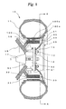
- Figure 1 is a cross-sectional view illustrating an outlined structure of a wheel used for an in-wheel motor system according to the first embodiment of the present invention
- Figure 2 is a cross-sectional view taken on line A-A of Figure 1.
- a wheel 10 is a wheel for an in-wheel motor system with an induction motor built therein and includes a tire 11 and a wheel 20 mounted with a tire 11.
- the wheel 20 has a rim section 21 for mounting the tire 11, and a disc section 22 for coupling the rim section 21 to a hub 12.
- stud bolts 13 vertically set on the hub 12 are passed through holes formed in the disc section 22 and secures the whole wheel 20 with hexagonal nuts 14 respectively.
- the hub 12 is rotatably supported on a wheel supporting section 15 through bearings or the like and rotates together with an axle 17.
- the axle 17 is included as driving force transmission means except the in-wheel motor system, and a disc brake 50 is assembled into as brake means.
- the disc brake 50 includes a brake disc 51 which is secured on the hub 12 and rotates together with the wheel 10, and a brake caliper 52 fixed on the wheel supporting section 15. By pressing a brake pad (not illustrated) in the brake caliper 52 against the brake disc 51, braking force is produced.
- the wheel supporting section 15 is fixed on a vehicle and supports the axle 10 through the hub 12.
- a stator supporting arm 16 extends toward an internal surface of a rim section 21, and the front end thereof is supported with a motor stator 30.
- the motor stator 30 has a stator magnetic substance 31 and a stator coil 32 wound therearound.
- the motor stator 30 has a partially cut shape, or has no total circumference, so as to bypass the brake caliper 52 as illustrated in Figure 2.
- a motor rotor 40 having a magnetic substance such as a permanent magnet is fixed all around so as to face the motor stator 30.
- the motor rotor 40 does not always need to be fitted all around. However, preferably, the motor rotor 40 should be fitted at all portions facing the motor stator 30 for higher efficiency.
- the motor rotor 40 may be fixed on an external surface of the rim section 21. Also, the rim section 21 or a disc section 22 may be constituted as the motor rotor 40.
- a drive source such as an engine
- an in-wheel motor system for a vehicle equipped with an axle 17 and a disc brake 50 is shown, however, it goes without saying that this embodiment is applicable to a vehicle equipped with only a drive source with a motor.
- the above configuration is just an example of an in-wheel motor system including an induction motor in a wheel and will not restrict types, configurations, or materials to be used.
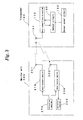
- FIG 3 is a view illustrating communication between a transponder and a monitor unit according to the first embodiment of the present invention
- Figure 4 is a view illustrating another communication between a transponder and a monitor unit according to the first embodiment of the present invention
- Figure 5 is an external perspective view of a transponder according to the first embodiment
- Figure 6 is a sectional side view of a transponder according to the first embodiment
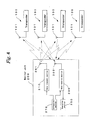
- Figure 7 is a block diagram illustrating a configuration of a transponder illustrated in Figures 5 and 6
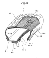
- Figure 8 is a view illustrating a mounting state of a transponder according to the first embodiment.
- the transponder 100 detects information of states of a wheel including a tire, such as acceleration, temperature, air pressure and rotational speed of a tire and transmits the information to a monitor unit 200 at a position distant from the tire.
- the transponder 100 is constituted of data transmit/receive antenna 101, a data transmit/receive section 110, a sensor circuit 130, and a sensor power circuit 150.
- a reference numeral 200 is a monitor unit consisting of a data transmit/receive antenna 201, a data transmit section 210, a data receive section 230, a calculation section 250, and an operation section 270.
- a transmit command of a question signal is inputted from the operation section 270, and the data transmit section 210 transmits the question signal through the transmit antenna 201.
- a reply signal is transmitted from the transponder 100 in response to the transmission, a receive command of the reply signal is inputted from the operation section 270, and the data receive section 230 receives the reply signal through a data receive antenna 102.
- the reply signal is outputted to the calculation section 250, and the calculation section 250 reads out tire information from the reply signal.
- the present invention is not limited to a case where one monitor unit 200 transmits and receives signals to/from one transponder 100 as illustrated in Figure 3, and communications with the plurality of transponders 100 may be made like a case where one monitor unit 200 reads out tire information from the respective transponders 100 mounted on the four wheels 10.
- a reply signal described later is transmitted including its own identification information, and the calculation section 250 stores identification information of the transponder 100 in advance, thus concurrently identifying the plurality of transponders 100.
- the signal transmission of the transponder 100 is not limited to the above embodiment, and for example, a reply signal maybe transmitted without need for receiving a question signal transmitted by the monitor unit 200.
- the transponder 100 consists of a transponder body 100a and a charging coil section 100b.
- the transponder body 100a is formed by molding an on-part disc-shaped multi-layer printed wiring circuit substrate 301 (hereinafter referred to as a "circuit substrate"), with resin 310, embedded with a circular loop-shaped data transmit/receive antenna 101 in an inter layer of the circuit substrate 301, and implemented with a storage device 152 and a plurality of chip-like electronic parts 303 and IC chips 304 on a surface of the circuit substrate 301.
- a columnar chip-like acceleration sensor 135 is implemented on a rear face of the circuit substrate 301.
- the on-part circuit substrate 301 is sealed with resin 310, and the resin 310 is formed into a flat and columnar shape.
- the charging coil section 100b is formed by molding a charging coil 157 with resin 310, and a charging coil 157 is connected with part of the chip-like electronic parts 303 of the transponder 100a through a lead wire 157a and sealed with the resin 310, and the resin 310 is formed into a flat and columnar shape.
- the charging coil 157 may use any coil and will not restrict types, configurations, or materials to be used.
- the present invention uses such a configuration that the charging coil section 100b has only the charging coil 157 as one embodiment, however, may use such all circuits to constitute a sensor power circuit 150 described later.
- a data transmit/receive section 110 is constituted of an antenna changing-over switch 111, a power circuit 112, an analog/digital (hereinafter referred to as "A/D") conversion circuit 113, a storage section 114, a central processing section 115 consisting of a CPU 115a and a digital/analog (hereinafter referred to as "D/A") conversion circuit 115b, and a transmit section 116 consisting of a modulation circuit 116a, an oscillation circuit 116b and a high-frequency amplification circuit 116c.
- A/D analog/digital
- D/A digital/analog
- the antenna changing-over switch 111 constituted of an electronic switch or the like, changes over the data transmit/receive antenna 101 to the power circuit 112 and either of the A/D conversion circuit 113 or the transmit section 116 for connection by a control signal from the CPU 115a.
- the antenna 101 is usually connected to the side of the power circuit 112.
- the power circuit 112 forms a known full-wave rectification circuit (second energy conversion means).
- the antenna 101 is connected to the input side of the power circuit 112 through the antenna changing-over switch 111.
- the power circuit 112 rectifies a high-frequency current induced in the antenna 101 to convert it into a DC current, which is outputted as a driving power source for other circuits such as the central processing section 115, the storage section 114 and the transmit section 116.
- the A/D conversion circuit 113 after detecting a received question signal, is converted into digital data and outputted to the CPU 115a.
- the central processing section 115 is constituted of the known CPU 115a and the D/A conversion circuit 115b.
- the CPU 115a when it is driven with power supplied and a question signal is inputted from the A/D conversion circuit 113, drives the sensor circuit 130, captures detected results of temperature and humidity, produces reply information including the detected results and its unique identification information, and transmits the information as a reply signal through the D/A conversion circuit 115b and the transmit section 116.
- the identification information are identification information unique to the respective transponders 100 stored in the storage section 114 consisting of a nonvolatile semiconductor memory capable of electric rewriting such as EEPROM (electrically Erasable Programmable Read-only Memory), and are previously stored in an area designated as being incapable of rewriting in the storage section 114 at the time of manufacturing the transponder 100.
- EEPROM electrically Erasable Programmable Read-only Memory
- the transmit section 116 consists of the modulation circuit 116a, the oscillation circuit 116b and the high-frequency amplification circuit 116c, and a carrier wave oscillated by the oscillation circuit 116b is modulated by the modulation circuit 116a based on an information signal inputted from the central processing section 115, which is then supplied to the antenna 101 through the high-frequency amplification circuit 116c and antenna changing-over switch 111.
- the sensor circuit 130 is constituted of the storage section 131, the CPU 132, the A/D conversion circuit 133, a power control section 134, and an acceleration sensor 135.
- the present invention uses, in this embodiment, the acceleration sensor 135 for detecting accelerations in three directions orthogonal to each other generated with the rotation of a wheel as a sensor for detecting information of an internal tire, however, may modify or add a temperature sensor, an air pressure sensor, or rotational speed sensor according to an object or application thereof.
- the CPU 132 makes communications with the CPU 115a of the transmit/receive section 110 and, upon receiving a request of acceleration information from the CPU 115a, acquires temperature information and pressure information detected by the acceleration sensor 135 through the A/D conversion circuit 133 and transmits the information to the CPU 115a.
- the power control section 134 constituted of, for example, an electronic switch and a boosting type power circuit and so on, turns on and off the electronic switch based on a control signal from the CPU 115a of the data transmit/receive section 110, converts the electric power outputted from the sensor power circuit 150 into the voltage required for circuit operation and supplies the voltage to the storage section 131, the CPU 132, the A/D conversion circuit 133 and the acceleration sensor 135. As described later, the power control section 134 can supply the electric power outputted from the sensor power circuit 150 in place of the power circuit 112.
- the sensor power circuit 150 is constituted of a rectification circuit 151 (energy conversion means), storage device 152, and a charging coil 157.
- the rectification circuit 151 is constituted of diodes 153, 154, a capacitor 155, and a resistor 156 to form a known full-wave rectification circuit.
- the input side of the rectification circuit 151 is connected to the charging coil 157, and the output side of the rectification circuit 151 is connected to the storage device 152 and to the power control section 134.
- the transponder body 100a is mounted on a surface of the motor rotor 40 provided so as to face the motor stator 30 on an internal surface of the rim section 21 in the tire, and the charging coil section 100b is embedded in the rotor 40 so that the axis of the charging coil 157 may be roughly perpendicular to a surface of the rotor 40.
- the charging coil section 100b is embedded in the rotor 40 for higher efficiency, however, may be mounted on a surface of the rotor 40.
- the tire 11 used in this embodiment is, for example, a known tubeless radial tire, and is constituted of a known cap tread 401, an under-tread 402, belts 403A, 403B and a carcass 404 and so on.
- the number of the transponders 100 mounted on the rotor 40 is not always to one and may be two or more.
- induced electromotive force described later increases by making the coil penetrate through a magnetic field produced by the motor stator 30.
- the in-wheel motor system when a predetermined three-phase AC current is supplied to the stator coil 32, a revolving magnetic field is produced around the motor stator 30.
- the revolving magnetic field causes the rim section 21 including the motor rotor 40 to receive rotational force and rotate along with the wheel 10.
- the electric current supplied at this time allows the motor stator 30 to produce a magnetic field, so that the magnetic flux penetrating through the charging coil 157 mounted in the transponder 100 changes to produce an induced electromotive force in the charging coil 157.
- the induced electromotive force will not cause energy loss by transmission and reception like an electromagnetic wave, therefore the sensor power circuit 150 can perform energy conversion with higher efficiency than the power circuit 112, and much larger electric energy can be achieved than the energy which the whole transponder 100 as well as the sensor circuit 130 requires.
- the transponder 100 consisting of the above configuration and the wheel 10 therewith, current is supplied to the stator coil 32 to produce a magnetic field, so that the magnetic flux penetrating through the charging coil 157 changes, the rectification circuit 151 rectifies the induced electromotive force produced by the charging coil 157 and converts it into DC current, thus the sensor power circuit 150 can supply electric energy to the sensor circuit 130 with higher efficiency than the power circuit 112 for driving the transmit/receive section 110 with an electromagnetic wave as medium.
- the current produced by rectifying an induced electromotive force generated at the charging coil 157 is much larger than the current the transponder 100 requires, therefore the storage device 152 is constituted of, for example, a large-capacity capacitor or a secondary battery for significant storage, thus the sensor power circuit 150 drives the sensor circuit 130 as well as the transmit/receive section 110 and, even under such a stopping state that the wheel is not running, the transponder 100 can be semi-permanently operated by the storage device 152 without need for a power supply.
- the mounting position of the transponder 100 is not limited to the rotor 40 and may be used if it has an effect of a magnetic field produced by the motor stator 30 in the wheel 10.
- the transponder 100 is not limited to what detects the information of the tire and may be used if it is applicable to the in-wheel motor system.
- the transponder 100 equipped with a temperature sensor fitted so as to be penetrated through a magnetic field produced by the motor stator 30, a temperature change in the brake disc 51 can be detected without need for a power supply.
- the transponder mounted on the wheel of the in-wheel motor system rectifies the induced electromagnetic force produced by the coil provided in the transponder for electricity storage, and thus can be used for applications where electric energy is supplied to an electric circuit provided on the wheel.
Abstract
Description
- The present invention relates to a transponder which does not require a power source used in an in-wheel motor system and a wheel therewith.
- To identify a tire or obtain information such as inner pressure, temperature and rotational speed of a tire, there is known a technique of such a type as to receive electric oscillating energy from a position distant from a specific tire and to transmit a signal from a transponder mounted on a wheel including the tire.
- The transponder consists of an integrated circuit and a case for protecting the integrated circuit and the shape thereof is small coin-shaped or columnar or the like.
- As this type of technique, there is conventionally proposed a transponder of which embedding position is set at the central portion of a front end level of carcass ply winding section or on a carcass ply outer surface of a pat-less section (for example, refer to Patent Literature 1).
- Furthermore, a pneumatic tire fitted with a transponder formed by improving a foregoing technique is proposed (for example, refer to patent Literature 2).
- That is, the transponder in the foregoing technique is a foreign substance for a tire and, if embedded into the tire, has a concern of some failure in the transponder itself due to high temperature and pressure received by the transponder during a vulcanization process for tire manufacture, an external force received by the transponder during tire load rolling, and heat or the like generated. To solve these problems, the pneumatic tire includes a pocket for transponder storage at a swelling section provided on an inner-periphery surface of a beads section of a toroidal tire.
- Since the swelling section having the pocket for transponder storage is provided at the beads section having little movement during running in the inner-periphery surface of the tire, there is no adverse effect on the tire and the transponder can freely advance and retreat from/into the pocket, therefore the stored transponder can be inspected or freely replaced as needed.
Patent Literature 1:Japanese Utility Model Laid-Open No. H2-123404
Patent Literature 2:Japanese Utility Model Laid-Open No. H7-13505 - However, most of conventional transponders use a battery to operate an internal electronic circuit respectively and, if the battery becomes exhausted, will not operate. Therefore, periodical replacement of the battery is required, which requires much time and trouble. In a structure having the transponder therein, battery replacement is not easy to perform.
- In view of the aforementioned problems, it is an object of the present invention to provide a transponder which does not require a power source used in an in-wheel motor system and a wheel therewith.
- To achieve the aforementioned object, the present invention proposes a transponder, which is provided in an in-wheel motor system for rotating the wheel together with a rotor by a magnetic field formed by passing a predetermined current through a coil of a stator built in a wheel and having a magnetic substance and the coil and which transmits information by a predetermined signal, comprising: another coil having a predetermined number of turns; and energy conversion means of converting induced electromotive force produced as a result of a flux density penetrating through another coil being changed by the magnetic field into electric energy for a transponder, wherein the transponder operates on the electric energy produced by the energy conversion means.
- According to a transponder consisting of the above structure, a magnetic field is formed by a coil supplied with current, and flux density penetrating through another coil changes to induced electromotive force. The energy conversion means converts the induced electromotive force into electric energy, and the electric energy drives the transponder.
- Furthermore, to achieve the aforementioned object, the present invention proposes a transponder, which is provided in an in-wheel motor system for rotating the wheel together with a rotor by a magnetic field formed by passing a fixed current through a coil of a stator built in a wheel and having a magnetic substance and the coil and which transmits information by a fixed signal, comprising: a main circuit including a central processing section for producing and outputting an electric signal indicating reply information and transmitting means for transmitting a reply signal based on the electric signal indicating the reply information outputted from the central processing section; a sensor section for detecting a predetermined physical value of the wheel and outputting the detected result with an electric signal; means of making the central processing section which captures the detected result by the sensor section and includes the detected result in the reply information; another coil having a predetermined number of turns; and energy conversion means of converting induced electromotive force produced as a result of a flux density penetrating through another coil being changed by the magnetic field into electric energy for a transponder, wherein the transponder operates on the electric energy produced by the energy conversion means.
- According to a transponder consisting of the above structure, an electric signal indicating reply information is produced by a central processing section. The sensor section detects the physical value of a wheel, and an electric signal of the detected result is outputted. Next, the main circuit includes the detected result in the reply information, and the transmission means transmits a reply signal based on the reply information. A magnetic field is formed by a coil supplied with a current, and flux density passing through another coil changes to induce an induced electromotive force. The energy conversion means converts the induced electromotive force into electric energy, thus driving the transponder.
- Furthermore, to achieve the aforementioned object, the present invention proposes a transponder, which is provided in an in-wheel motor system for rotating the wheel together with a rotor by a magnetic field formed by passing a predetermined current through a coil of a stator built in a wheel and having a magnetic substance and the coil and which transmits information by a predetermined signal, comprising: a main circuit including a central processing section for producing and outputting an electric signal indicating reply information and transmitting means for transmitting a reply signal based on the electric signal indicating the reply information outputted from the central processing section; a sensor section for detecting a predetermined physical value of the wheel and outputting the detected result with an electric signal; means of making the central processing section which captures the detected result by the sensor section and includes the detected result in the reply information; another coil having a predetermined number of turns; energy conversion means of converting induced electromotive force produced as a result of a flux density penetrating through another coil being changed by the magnetic field into electric energy for a transponder; and a storage device for storing electric energy produced by the energy conversion means, wherein the transponder operates on the electric energy stored in the storage device.
- According to a transponder consisting of the above structure, an electric signal indicating reply information is produced by a central processing section. The sensor section detects the physical value of a wheel, and an electric signal of the detected result is outputted. Next, the main circuit includes the detected result in the reply information, and the transmission means transmits a reply signal based on the reply information. A magnetic field is formed by a coil supplied with a current, and flux density passing through another coil changes to induce an induced electromotive force. The electric energy produced by the energy conversion means is stored in the storage device and drives the transponder. If no electric energy is produced by the energy conversion means, the transponder is driven by the electric energy stored in the storage device.
- Furthermore, the present invention proposes a transponder having the above structure, further comprising: receiving means of receiving a predetermined electromagnetic wave and; second energy conversion means for converting the energy of the electromagnetic wave received by the receiving means into electric energy, wherein the transponder operates on concurrent use of the electric energy produced by the second energy conversion means and the electric energy produced by the energy conversion means.
- According to a transponder having the above structure, when a predetermined electromagnetic wave is received by the receiving means, the electromagnetic wave energy is converted into electric energy by the second energy conversion means. Concurrent use of the electric energy and the electric energy produced by the energy conversion means drives the transponder.
- Furthermore, the present invention proposes a transponder having the above structure, wherein the storage device consisting of a secondary battery.
- According to a transponder having the above structure, a secondary battery is used as the storage device.
- Furthermore, the present invention proposes a transponder having the above structure, wherein the storage device constituted of a large-capacity capacitor.
- According to a transponder having the above structure, a large-capacity capacitor is used as the storage device.
- Furthermore, the present invention proposes a transponder having the above structure, further comprising information storage means for storing unique identification information, wherein the central processing section having means of reading out identification information of the information storage means and including the information in the reply information.
- According to a transponder having the above structure, information storage means stores identification information unique to the transponder, and the identification information is included in the reply information for transmission. Thus, even if a plurality of transponders concurrently transmit the reply signals, the transponder can be identified according to the identification information.
- Furthermore, the present invention proposes a transponder having the above structure, wherein the sensor section includes at least any one of an acceleration sensor, a temperature sensor and an air pressure sensor as the sensor section.
- According to a transponder having the above structure, the sensor section includes at least any one of an acceleration sensor, a temperature sensor and an air pressure sensor, and information of the wheel detected by the sensor is included in the reply information for transmission.
- Furthermore, the present invention proposes a transponder having the above structure, wherein another coil is disposed so as to penetrate through a magnetic field formed by the coil.
- According to a transponder having the above structure, another coil is disposed so as to penetrate through a magnetic field formed by the coil. Thus, flux density penetrating through another coil changes more significantly, so that induced electromotive force to be induced increases.
- Furthermore, the present invention proposes a transponder having the above structure, wherein another coil embedded in the rotor.
- According to a transponder having the above structure, another coil is embedded in the rotor. Thus, flux density penetrating through another coil changes more significantly, and induced electromotive force to be induced increases.
- Furthermore, to achieve the aforementioned object, the present invention proposes a wheel, which builds-in an in-wheel motor system equipped with a stator having a magnetic substance and a coil and a rotor and which rotates together with the rotor by a magnetic field formed by supplying a predetermined current to the coil of the stator, comprising: a transponder for transmitting information with a predetermined signal, wherein the transponder includes another coil having a predetermined number of turns and energy conversion means of converting induced electromotive force produced as a result of a flux density penetrating through another coil being changed by the magnetic field into electric energy for a transponder and operates on the electric energy produced by the energy conversion means.
- According to a wheel having the above structure, a magnetic field is formed by a coil supplied with current, and flux density penetrating through another coil changes to generate induced electromotive force. The induced electromotive force is converted into an electric energy for a transponder by energy conversion means, thus providing a transponder operating on the electric energy.
- Furthermore, to achieve the aforementioned object, the present invention proposes a wheel, which builds-in an in-wheel motor system equipped with a stator having a magnetic substance and a coil and a rotor and which rotates together with the rotor by a magnetic field formed by supplying a predetermined current to the coil of the stator, comprising a transponder for transmitting information with a predetermined signal, wherein the transponder includes a main circuit including a central processing section for producing and outputting an electric signal indicating reply information and transmitting means for transmitting a reply signal based on the electric signal indicating the reply information outputted from the central processing section, a sensor section for detecting a predetermined physical value of the wheel and outputting the detected result with an electric signal, means of making the central processing section which captures the detected result by the sensor section and includes the detected result in the reply information, another coil having a predetermined number of turns, and energy conversion means of converting induced electromotive force produced as a result of a flux density penetrating through another coil being changedby the magnetic field into electric energy for a transponder and operates on the electric energy produced by the energy conversion means.
- According to a wheel consisting of the above structure, an electric signal indicating reply information is produced by a central processing section. The sensor section detects the physical value of a wheel, and an electric signal of the detected result is outputted. Next, the main circuit includes the detected result in the reply information, and the transmission means transmits a reply signal based on the reply information. A magnetic field is formed by a coil supplied with a current, and flux density passing through another coil changes to induce an induced electromotive force. The energy conversion means converts the induced electromotive force into electric energy for a transponder, thus driving the transponder.
- Furthermore, to achieve the aforementioned object, the present invention proposes a wheel, which builds-in an in-wheel motor system equipped with a stator having a magnetic substance and a coil and a rotor and which rotates together with the rotor by a magnetic field formed by supplying a predetermined current to the coil of the stator, comprising a transponder for transmitting information with a predetermined signal, wherein the transponder includes a main circuit including a central processing section for producing and outputting an electric signal indicating reply information and transmitting means for transmitting a reply signal based on the electric signal indicating the reply information outputted from the central processing section, a sensor section for detecting a predetermined physical value of the wheel and outputting the detected result with an electric signal, means of making the central processing section which captures the detected result by the sensor section and includes the detected result in the reply information, another coil having a predetermined number of turns, energy conversion means of converting induced electromotive force produced as a result of a flux density penetrating through another coil being changed by the magnetic field into electric energy for a transponder, and a storage device for storing electric energy produced by the energy conversion means and operates on the electric energy stored in the storage device.
- According to a wheel consisting of the above structure, in a transponder, an electric signal indicating reply information is produced by a central processing section. The sensor section detects the physical value of a wheel, and an electric signal of the detected result is outputted. Next, the main circuit includes the detected result in the reply information, and the transmission means transmits a reply signal based on the reply information. A magnetic field is formed by a coil supplied with a current, and flux density passing through another coil changes to induce an induced electromotive force. The electric energy produced by the energy conversion means is stored in the storage device and drives the transponder. If no electric energy is produced by the energy conversion means, the transponder is driven by the electric energy stored in the storage device.
- Furthermore, the present invention proposes a wheel having the above structure, wherein the transponder includes receiving means of receiving a predetermined electromagnetic wave and second energy conversion means for converting the energy of the electromagnetic wave received by the receiving means into electric energy and operates on concurrent use of the electric energy produced by the second energy conversion means and the electric energy produced by the energy conversion means.
- According to a wheel having the above structure, when a predetermined electromagnetic wave is received by the receiving means, the electromagnetic wave energy is converted into electric energy by the second energy conversion means. Concurrent use of the electric energy and the electric energy produced by the energy conversion means drives the transponder.
- Furthermore, the present invention proposes a wheel having the above structure, wherein: the transponder has information storage means of storing unique identification information; and the central processing section has means of reading out identification information of the information storage means and including the information in the reply information.
- According to a wheel having the above structure, information storage means stores identification information unique to the transponder, and the identification information is included in the reply information for transmission. Thus, even if a plurality of transponders concurrently transmit the reply signals, the transponder can be identified according to the identification information.
- According to a transponder and a wheel therewith of the present invention, an electric current is supplied to a coil to form a magnetic field and to change flux density penetrating through another coil, and induced electric power generated at another coil is rectified, thus supplying electric energy to a sensor section more efficiently than a case where an electromagnetic wave is used as medium.
- Since the electric current obtained by rectifying induced electric power generated at another coil is significantly larger than electric current required by a transponder, a storage device is constituted of a large-capacity capacitor or a secondary battery for sufficient storage, thus yielding very excellent effects that a main circuit as well as the sensor section can be driven and a transponder can be semipermanently operated by a storage device without need for a power supply.
- The foregoing and/or further objects, features and advantages of the invention will become more apparent from the following description of preferred embodiments with reference to the accompanying drawings.
-
- Figure 1 is a cross-sectional view illustrating an outlined structure of a wheel used for an in-wheel motor system according to the first embodiment of the present invention;
- Figure 2 is a cross-sectional view taken on line A-A of Figure 1;
- Figure 3 is aview illustrating communication between a transponder and a monitor unit according to the first embodiment of the present invention;
- Figure 4 is a view illustrating another communication between a transponder and a monitor unit according to the first embodiment of the present invention;
- Figure 5 is an external perspective view of a transponder according to the first embodiment of the present invention;
- Figure 6 is a sectional side view of a transponder according to the first embodiment of the present invention;
- Figure 7 is a block diagram illustrating a configuration of a transponder illustrated in Figures 5 and 6; and
- Figure 8 is a view illustrating a mounting state of a transponder according to the first embodiment of the present invention.
- 10 ... wheel, 11 ... tire, 12 ... hub, 13 ... stud bolt, 14 ... hexagonal nut, 15 ... wheel supporting section, 16 ... stator supporting arm, 17 ... axle, 20 ... wheel, 21 ... rim section, 22 ... disc section, 30 ... motor stator, 31 ... stator magnetic substance, 32 ... stator coil, 40 ... motor rotor, 50 ... disc brake, 51 ... brake disc, 52 ... brake caliper, 100 ... transponder, 100a ... transponder body, 100b ... charging coil section, 101 ... data transmit/receive antenna, 110 ... data transmit/receive section, 130 ... sensor circuit, 150 ... sensor power circuit, 151... rectification circuit (energy conversion means), 152 ... storage device, 153 and 154 ... diodes, 155 ... capacitor, 156 ... resistor, 157 ... charging coil, 157a ... lead wire, 200 ... monitor unit, 201 ... data transmit antenna, 202 ... data receive antenna, 210 ... data transmit section, 230 ... data receive section, 250 ... calculation section, 270 ... operation section, 301 ... multi-layer printed wiring circuit substrate, 303 ... chip-like electronic part, 304 ... IC chip, 310 ... resin portion, 401 ... cap tread, 402 ... under tread, 403A and 403B ... belt, 404 ... carcass
- Reference will be made in detail to preferred embodiments of the invention, examples of which are illustrated in the accompanying drawings.
- Figure 1 is a cross-sectional view illustrating an outlined structure of a wheel used for an in-wheel motor system according to the first embodiment of the present invention, and Figure 2 is a cross-sectional view taken on line A-A of Figure 1.
- In figures, a
wheel 10 is a wheel for an in-wheel motor system with an induction motor built therein and includes atire 11 and awheel 20 mounted with atire 11. Thewheel 20 has arim section 21 for mounting thetire 11, and adisc section 22 for coupling therim section 21 to ahub 12. - Usually four to six
stud bolts 13 vertically set on thehub 12 are passed through holes formed in thedisc section 22 and secures thewhole wheel 20 withhexagonal nuts 14 respectively. Thehub 12 is rotatably supported on awheel supporting section 15 through bearings or the like and rotates together with anaxle 17. - In the case of a hybrid type vehicle equipped with a drive source such as an engine, the
axle 17 is included as driving force transmission means except the in-wheel motor system, and adisc brake 50 is assembled into as brake means. - The
disc brake 50 includes abrake disc 51 which is secured on thehub 12 and rotates together with thewheel 10, and abrake caliper 52 fixed on thewheel supporting section 15. By pressing a brake pad (not illustrated) in thebrake caliper 52 against thebrake disc 51, braking force is produced. - The
wheel supporting section 15 is fixed on a vehicle and supports theaxle 10 through thehub 12. In thewheel supporting section 15, a stator supporting arm 16 extends toward an internal surface of arim section 21, and the front end thereof is supported with amotor stator 30. Themotor stator 30 has a statormagnetic substance 31 and astator coil 32 wound therearound. In this embodiment, themotor stator 30 has a partially cut shape, or has no total circumference, so as to bypass thebrake caliper 52 as illustrated in Figure 2. However, it is preferable that the wheel not assembled with thedisc brake 50 should have the total circumference. - On the internal surface of the
rim section 21, amotor rotor 40 having a magnetic substance such as a permanent magnet is fixed all around so as to face themotor stator 30. Themotor rotor 40 does not always need to be fitted all around. However, preferably, themotor rotor 40 should be fitted at all portions facing themotor stator 30 for higher efficiency. Furthermore, themotor rotor 40 may be fixed on an external surface of therim section 21. Also, therim section 21 or adisc section 22 may be constituted as themotor rotor 40. - In this embodiment, a drive source such as an engine is included, and an in-wheel motor system for a vehicle equipped with an
axle 17 and adisc brake 50 is shown, however, it goes without saying that this embodiment is applicable to a vehicle equipped with only a drive source with a motor. Moreover, the above configuration is just an example of an in-wheel motor system including an induction motor in a wheel and will not restrict types, configurations, or materials to be used. - Next, a description will be made on a configuration of a
transponder 100. Figure 3 is a view illustrating communication between a transponder and a monitor unit according to the first embodiment of the present invention, Figure 4 is a view illustrating another communication between a transponder and a monitor unit according to the first embodiment of the present invention, Figure 5 is an external perspective view of a transponder according to the first embodiment, Figure 6 is a sectional side view of a transponder according to the first embodiment, Figure 7 is a block diagram illustrating a configuration of a transponder illustrated in Figures 5 and 6, and Figure 8 is a view illustrating a mounting state of a transponder according to the first embodiment. - The
transponder 100 detects information of states of a wheel including a tire, such as acceleration, temperature, air pressure and rotational speed of a tire and transmits the information to amonitor unit 200 at a position distant from the tire. - In Figure 3, the
transponder 100 is constituted of data transmit/receiveantenna 101, a data transmit/receivesection 110, asensor circuit 130, and asensor power circuit 150. Areference numeral 200 is a monitor unit consisting of a data transmit/receiveantenna 201, a data transmit section 210, a data receivesection 230, acalculation section 250, and anoperation section 270. - In reading out data of the acceleration of the
tire 11 from thetransponder 100, a transmit command of a question signal is inputted from theoperation section 270, and the data transmit section 210 transmits the question signal through the transmitantenna 201. When a reply signal is transmitted from thetransponder 100 in response to the transmission, a receive command of the reply signal is inputted from theoperation section 270, and the data receivesection 230 receives the reply signal through a data receive antenna 102. The reply signal is outputted to thecalculation section 250, and thecalculation section 250 reads out tire information from the reply signal. - The present invention is not limited to a case where one
monitor unit 200 transmits and receives signals to/from onetransponder 100 as illustrated in Figure 3, and communications with the plurality oftransponders 100 may be made like a case where onemonitor unit 200 reads out tire information from therespective transponders 100 mounted on the fourwheels 10. In this case, a reply signal described later is transmitted including its own identification information, and thecalculation section 250 stores identification information of thetransponder 100 in advance, thus concurrently identifying the plurality oftransponders 100. - The signal transmission of the
transponder 100 is not limited to the above embodiment, and for example, a reply signal maybe transmitted without need for receiving a question signal transmitted by themonitor unit 200. - In Figures 5 and 6, the
transponder 100 consists of a transponder body 100a and a charging coil section 100b. - The transponder body 100a is formed by molding an on-part disc-shaped multi-layer printed wiring circuit substrate 301 (hereinafter referred to as a "circuit substrate"), with
resin 310, embedded with a circular loop-shaped data transmit/receiveantenna 101 in an inter layer of thecircuit substrate 301, and implemented with astorage device 152 and a plurality of chip-likeelectronic parts 303 andIC chips 304 on a surface of thecircuit substrate 301. On a rear face of thecircuit substrate 301, a columnar chip-like acceleration sensor 135 is implemented. The on-part circuit substrate 301 is sealed withresin 310, and theresin 310 is formed into a flat and columnar shape. - The charging coil section 100b is formed by molding a charging
coil 157 withresin 310, and a chargingcoil 157 is connected with part of the chip-likeelectronic parts 303 of the transponder 100a through a lead wire 157a and sealed with theresin 310, and theresin 310 is formed into a flat and columnar shape. The chargingcoil 157 may use any coil and will not restrict types, configurations, or materials to be used. The present invention uses such a configuration that the charging coil section 100b has only the chargingcoil 157 as one embodiment, however, may use such all circuits to constitute asensor power circuit 150 described later. - In a block diagram of the
transponder 100 illustrated in Figure 7, a data transmit/receivesection 110 is constituted of an antenna changing-overswitch 111, apower circuit 112, an analog/digital (hereinafter referred to as "A/D")conversion circuit 113, a storage section 114, acentral processing section 115 consisting of aCPU 115a and a digital/analog (hereinafter referred to as "D/A")conversion circuit 115b, and a transmitsection 116 consisting of amodulation circuit 116a, anoscillation circuit 116b and a high-frequency amplification circuit 116c. - The antenna changing-over
switch 111, constituted of an electronic switch or the like, changes over the data transmit/receiveantenna 101 to thepower circuit 112 and either of the A/D conversion circuit 113 or the transmitsection 116 for connection by a control signal from theCPU 115a. Theantenna 101 is usually connected to the side of thepower circuit 112. - The
power circuit 112 forms a known full-wave rectification circuit (second energy conversion means). Theantenna 101 is connected to the input side of thepower circuit 112 through the antenna changing-overswitch 111. Thepower circuit 112 rectifies a high-frequency current induced in theantenna 101 to convert it into a DC current, which is outputted as a driving power source for other circuits such as thecentral processing section 115, the storage section 114 and the transmitsection 116. - The A/
D conversion circuit 113, after detecting a received question signal, is converted into digital data and outputted to theCPU 115a. - The
central processing section 115 is constituted of the knownCPU 115a and the D/A conversion circuit 115b. TheCPU 115a, when it is driven with power supplied and a question signal is inputted from the A/D conversion circuit 113, drives thesensor circuit 130, captures detected results of temperature and humidity, produces reply information including the detected results and its unique identification information, and transmits the information as a reply signal through the D/A conversion circuit 115b and the transmitsection 116. - The identification information are identification information unique to the
respective transponders 100 stored in the storage section 114 consisting of a nonvolatile semiconductor memory capable of electric rewriting such as EEPROM (electrically Erasable Programmable Read-only Memory), and are previously stored in an area designated as being incapable of rewriting in the storage section 114 at the time of manufacturing thetransponder 100. - The transmit
section 116 consists of themodulation circuit 116a, theoscillation circuit 116b and the high-frequency amplification circuit 116c, and a carrier wave oscillated by theoscillation circuit 116b is modulated by themodulation circuit 116a based on an information signal inputted from thecentral processing section 115, which is then supplied to theantenna 101 through the high-frequency amplification circuit 116c and antenna changing-overswitch 111. - The
sensor circuit 130 is constituted of thestorage section 131, theCPU 132, the A/D conversion circuit 133, apower control section 134, and anacceleration sensor 135. The present invention uses, in this embodiment, theacceleration sensor 135 for detecting accelerations in three directions orthogonal to each other generated with the rotation of a wheel as a sensor for detecting information of an internal tire, however, may modify or add a temperature sensor, an air pressure sensor, or rotational speed sensor according to an object or application thereof. - The
CPU 132 makes communications with theCPU 115a of the transmit/receivesection 110 and, upon receiving a request of acceleration information from theCPU 115a, acquires temperature information and pressure information detected by theacceleration sensor 135 through the A/D conversion circuit 133 and transmits the information to theCPU 115a. - The
power control section 134, constituted of, for example, an electronic switch and a boosting type power circuit and so on, turns on and off the electronic switch based on a control signal from theCPU 115a of the data transmit/receivesection 110, converts the electric power outputted from thesensor power circuit 150 into the voltage required for circuit operation and supplies the voltage to thestorage section 131, theCPU 132, the A/D conversion circuit 133 and theacceleration sensor 135. As described later, thepower control section 134 can supply the electric power outputted from thesensor power circuit 150 in place of thepower circuit 112. - The
sensor power circuit 150 is constituted of a rectification circuit 151 (energy conversion means),storage device 152, and a chargingcoil 157. Therectification circuit 151 is constituted ofdiodes capacitor 155, and aresistor 156 to form a known full-wave rectification circuit. The input side of therectification circuit 151 is connected to the chargingcoil 157, and the output side of therectification circuit 151 is connected to thestorage device 152 and to thepower control section 134. - As illustrated in Figure 8, the transponder body 100a is mounted on a surface of the
motor rotor 40 provided so as to face themotor stator 30 on an internal surface of therim section 21 in the tire, and the charging coil section 100b is embedded in therotor 40 so that the axis of the chargingcoil 157 may be roughly perpendicular to a surface of therotor 40. Preferably, the charging coil section 100b is embedded in therotor 40 for higher efficiency, however, may be mounted on a surface of therotor 40. - The
tire 11 used in this embodiment is, for example, a known tubeless radial tire, and is constituted of a knowncap tread 401, an under-tread 402,belts 403A, 403B and acarcass 404 and so on. The number of thetransponders 100 mounted on therotor 40 is not always to one and may be two or more. In the chargingcoil 157, induced electromotive force described later increases by making the coil penetrate through a magnetic field produced by themotor stator 30. - In the in-wheel motor system, when a predetermined three-phase AC current is supplied to the
stator coil 32, a revolving magnetic field is produced around themotor stator 30. The revolving magnetic field causes therim section 21 including themotor rotor 40 to receive rotational force and rotate along with thewheel 10. - The electric current supplied at this time allows the
motor stator 30 to produce a magnetic field, so that the magnetic flux penetrating through the chargingcoil 157 mounted in thetransponder 100 changes to produce an induced electromotive force in the chargingcoil 157. The induced electromotive force will not cause energy loss by transmission and reception like an electromagnetic wave, therefore thesensor power circuit 150 can perform energy conversion with higher efficiency than thepower circuit 112, and much larger electric energy can be achieved than the energy which thewhole transponder 100 as well as thesensor circuit 130 requires. - According to the
transponder 100 consisting of the above configuration and thewheel 10 therewith, current is supplied to thestator coil 32 to produce a magnetic field, so that the magnetic flux penetrating through the chargingcoil 157 changes, therectification circuit 151 rectifies the induced electromotive force produced by the chargingcoil 157 and converts it into DC current, thus thesensor power circuit 150 can supply electric energy to thesensor circuit 130 with higher efficiency than thepower circuit 112 for driving the transmit/receivesection 110 with an electromagnetic wave as medium. - The current produced by rectifying an induced electromotive force generated at the charging
coil 157 is much larger than the current thetransponder 100 requires, therefore thestorage device 152 is constituted of, for example, a large-capacity capacitor or a secondary battery for significant storage, thus thesensor power circuit 150 drives thesensor circuit 130 as well as the transmit/receivesection 110 and, even under such a stopping state that the wheel is not running, thetransponder 100 can be semi-permanently operated by thestorage device 152 without need for a power supply. - The mounting position of the
transponder 100 is not limited to therotor 40 and may be used if it has an effect of a magnetic field produced by themotor stator 30 in thewheel 10. Thetransponder 100 is not limited to what detects the information of the tire and may be used if it is applicable to the in-wheel motor system. - For example, by mounting in the
brake disc 51 thetransponder 100 equipped with a temperature sensor fitted so as to be penetrated through a magnetic field produced by themotor stator 30, a temperature change in thebrake disc 51 can be detected without need for a power supply. - It is further understood that the present invention is not limited to the details of configurations and arrangements of foregoing embodiments and that various changes and modifications may be made in the present invention without departing from the spirit and scope thereof.
- The transponder mounted on the wheel of the in-wheel motor system rectifies the induced electromagnetic force produced by the coil provided in the transponder for electricity storage, and thus can be used for applications where electric energy is supplied to an electric circuit provided on the wheel.
Claims (15)
- A transponder, which is provided in an in-wheel motor system for rotating the wheel together with a rotor by a magnetic field formed by passing a predetermined current through a coil of a stator built in a wheel and having a magnetic substance and the coil and which transmits information by a predetermined signal, comprising:another coil having a predetermined number of turns; andenergy conversion means of converting induced electromotive force produced as a result of a flux density penetrating through another coil being changed by the magnetic field into electric energy for a transponder, wherein the transponder operates on the electric energy produced by the energy conversion means.
- A transponder, which is provided in an in-wheel motor system for rotating the wheel together with a rotor by a magnetic field formed by passing a predetermined current through a coil of a stator built in a wheel and having a magnetic substance and the coil and which transmits information by a predetermined signal, comprising:amain circuit including a central processing section for producing and outputting an electric signal indicating reply information and transmitting means for transmitting a reply signal based on the electric signal indicating the reply information outputted from the central processing section;a sensor section for detecting a predetermined physical value of the wheel and outputting the detected result with an electric signal;means of making the central processing section which captures the detected result by the sensor section and includes the detected result in the reply information;another coil having a predetermined number of turns; andenergy conversion means which converts induced electromotive force produced as a result of a flux density penetrating through another coil being changedby the magnetic field into electric energy for a transponder, wherein the transponder operates on the electric energy produced by the energy conversion means.
- A transponder, which is provided in an in-wheel motor system for rotating the wheel together with a rotor by a magnetic field formed by passing a predetermined current through a coil of a stator built in a wheel and having a magnetic substance and the coil and which transmits information by a predetermined signal, comprising:amain circuit including a central processing section for producing and outputting an electric signal indicating reply information and transmitting means for transmitting a reply signal based on the electric signal indicating the reply information outputted from the central processing section;a sensor section for detecting a predetermined physical value of the wheel and outputting the detected result with an electric signal;means of making the central processing section which captures the detected result by the sensor section and includes the detected result in the reply information;another coil having a predetermined number of turns;energy conversion means of converting induced electromotive force produced as a result of a flux density penetrating through another coil being changed by the magnetic field into electric energy for a transponder; anda storage device for storing electric energy produced by the energy conversion means, wherein the transponder operates on the electric energy stored in the storage device.
- The transponder according to claim 2, further comprising:receiving means of receiving a predetermined electromagnetic wave and;second energy conversion means for converting the energy of the electromagnetic wave received by the receivingmeans into electric energy, wherein the transponder operates on concurrent use of the electric energy produced by the second energy conversion means and the electric energy produced by the energy conversion means.
- The transponder according to claim 3, wherein the storage device consists of a secondary battery.
- The transponder according to claim 3, wherein the storage device consists of a large-capacity capacitor.
- The transponder according to claim 2, further comprising information storage means for storing unique identification information, wherein the central processing section has means of reading out identification information of the information storage means and including the information in the reply information.
- The transponder according to claim 2, wherein the sensor section includes at least any one of an acceleration sensor, a temperature sensor and an air pressure sensor.
- The transponder according to claim 1, wherein another coil is disposed so as to penetrate through a magnetic field formed by the coil.
- The transponder according to claim 1, wherein another coil is embedded in the rotor.
- A wheel, which builds-in an in-wheel motor system equipped with a stator having a magnetic substance and a coil and a rotor and which rotates together with the rotor by a magnetic field formed by supplying a predetermined current to the coil of the stator, comprising a transponder for transmitting information with a predetermined signal, wherein the transponder includes another coil having a predetermined number of turns and energy conversion means of converting induced electromotive force produced as a result of a flux density penetrating through another coil being changed by the magnetic field into electric energy for a transponder and operates on the electric energy produced by the energy conversion means.
- A wheel, which builds-in an in-wheel motor system equipped with a stator having a magnetic substance and a coil and a rotor and which rotates together with the rotor by a magnetic field formed by supplying a predetermined current to the coil of the stator, comprising a transponder for transmitting information with a predetermined signal, wherein the transponder includes a main circuit including a central processing section for producing and outputting an electric signal indicating reply information and transmitting means for transmitting a reply signal based on the electric signal indicating the reply information outputted from the central processing section, a sensor section for detecting a predetermined physical value of the wheel and outputting the detected result with an electric signal, means of making the central processing section which captures the detected result by the sensor section and includes the detected result in the reply information, another coil having a predetermined number of turns, and energy conversion means of converting induced electromotive force produced as a result of a flux density penetrating through another coil being changed by the magnetic field into electric energy for a transponder and operates on the electric energy produced by the energy conversion means.
- A wheel, which builds-in an in-wheel motor system equipped with a stator having a magnetic substance and a coil and a rotor and which rotates together with the rotor by a magnetic field formed by supplying a predetermined current to the coil of the stator, comprising a transponder for transmitting information with a predetermined signal, wherein the transponder includes a main circuit including a central processing section for producing and outputting an electric signal indicating reply information and transmitting means for transmitting a reply signal based on the electric signal indicating the reply information outputted from the central processing section, a sensor section for detecting a predetermined physical value of the wheel and outputting the detected result with an electric signal, means of making the central processing section which captures the detected result by the sensor section and includes the detected result in the reply information, another coil having a predetermined number of turns, energy conversion means of converting induced electromotive force produced as a result of a flux density penetrating through another coil being changed by the magnetic field into electric energy for a transponder, and a storage device for storing electric energy produced by the energy conversionmeans and operates on the electric energy stored in the storage device.
- The wheel according to claim 12, wherein the transponder includes receiving means of receiving a predetermined electromagnetic wave and second energy conversion means for converting the energy of the electromagnetic wave received by the receiving means into electric energy and operates on concurrent use of the electric energy produced by the second energy conversion means and the electric energy produced by the energy conversion means.
- The wheel according to claim 12, wherein:the transponder includes information storage means of storing unique identification information; andthe central processing section has means of reading out identification information of the information storage means and including the information in the reply information.
Applications Claiming Priority (2)
| Application Number | Priority Date | Filing Date | Title |
|---|---|---|---|
| JP2004120258A JP4347121B2 (en) | 2004-04-15 | 2004-04-15 | Transponder used for in-wheel motor system and wheel equipped with the transponder |
| PCT/JP2005/006598 WO2005100074A1 (en) | 2004-04-15 | 2005-04-04 | In-wheel motor system-use transponder and wheel provided with it |
Publications (3)
| Publication Number | Publication Date |
|---|---|
| EP1757480A1 true EP1757480A1 (en) | 2007-02-28 |
| EP1757480A4 EP1757480A4 (en) | 2012-02-08 |
| EP1757480B1 EP1757480B1 (en) | 2013-02-27 |
Family
ID=35149868
Family Applications (1)
| Application Number | Title | Priority Date | Filing Date |
|---|---|---|---|
| EP05728847A Expired - Fee Related EP1757480B1 (en) | 2004-04-15 | 2005-04-04 | Transponder for in-wheel motor system and wheel therewith |
Country Status (4)
| Country | Link |
|---|---|
| US (1) | US7719412B2 (en) |
| EP (1) | EP1757480B1 (en) |
| JP (1) | JP4347121B2 (en) |
| WO (1) | WO2005100074A1 (en) |
Cited By (3)
| Publication number | Priority date | Publication date | Assignee | Title |
|---|---|---|---|---|
| WO2010003474A1 (en) | 2008-07-09 | 2010-01-14 | Sew-Eurodrive Gmbh & Co. Kg | Separately excited electrical synchronous machine and method for operating a synchronous machine |
| EP2728315A3 (en) * | 2012-10-30 | 2016-11-30 | Yokogawa Electric Corporation | Wireless device, sensor unit, wireless unit, and method for setting wireless device |
| US10218533B2 (en) | 2013-05-20 | 2019-02-26 | Yokogawa Electric Corporation | Wireless device and interface module |
Families Citing this family (14)
| Publication number | Priority date | Publication date | Assignee | Title |
|---|---|---|---|---|
| US7363806B2 (en) * | 2006-06-22 | 2008-04-29 | Silicon Valley Micro C Corp. | Tire parameter monitoring system with inductive power source |
| US8841785B2 (en) * | 2008-04-15 | 2014-09-23 | Infineon Technologies Ag | Energy harvester |
| JP5251223B2 (en) * | 2008-04-17 | 2013-07-31 | 横浜ゴム株式会社 | Electric vehicle control device |
| DE102010011124A1 (en) * | 2010-03-11 | 2011-12-15 | Andreas Stadlmeier | System for optimum tire pressure control in vehicles, has compact and functional design structure with compressed air generation mechanism and energy supply mechanism |
| KR101217846B1 (en) * | 2010-06-22 | 2013-01-03 | 덕산메카시스 주식회사 | Throw type compact reconnaissance |
| EP2423094B1 (en) | 2010-08-31 | 2014-04-02 | Chiu-Hsiang Lo | Electric wheel for electric vehicles |
| US20120075070A1 (en) * | 2010-09-27 | 2012-03-29 | General Electric Company | Real time measurement of rotor surface |
| US8348798B2 (en) * | 2010-10-01 | 2013-01-08 | Chiu-Hsiang Lo | Hub motor for electric vehicles |
| KR101238712B1 (en) | 2011-10-10 | 2013-03-04 | 소치재 | In-wheel motor for converting |
| ES2639312T3 (en) * | 2012-01-20 | 2017-10-26 | Chengdu Youyang Electromechanical Product Design Co. Ltd. | Wheel hub, wheel for motor vehicle with wheel hub, and electric vehicle |
| KR101552982B1 (en) * | 2012-07-12 | 2015-09-14 | 현대모비스 주식회사 | In-wheel motor and in-wheel working device |
| JP6286165B2 (en) * | 2013-09-24 | 2018-02-28 | Ntn株式会社 | In-wheel motor drive device |
| JP2018112971A (en) * | 2017-01-13 | 2018-07-19 | 株式会社荏原製作所 | Magnetic power generation type measuring device |
| US10555058B2 (en) * | 2018-06-27 | 2020-02-04 | Aktiebolaget Skf | Wireless condition monitoring sensor with near field communication commissioning hardware |
Citations (5)
| Publication number | Priority date | Publication date | Assignee | Title |
|---|---|---|---|---|
| EP0094978A1 (en) * | 1982-05-24 | 1983-11-30 | Magnet-Motor Gesellschaft für magnetmotorische Technik mbH | Rotatable electrical machine |
| EP0249808A1 (en) * | 1986-06-18 | 1987-12-23 | Magnet-Motor Gesellschaft für magnetmotorische Technik mbH | Drive unit for an electrically powered vehicle |
| US5513525A (en) * | 1991-01-09 | 1996-05-07 | Texas Instruments Incorporated | Arrangement for monitoring the operating state of vehicle pneumatic tires mounted on wheel rims |
| DE19816936A1 (en) * | 1998-04-16 | 1999-10-21 | Siemens Ag | Antenna transponder arrangement for power transmission and angle measurement |
| EP1227018A2 (en) * | 2001-01-29 | 2002-07-31 | The Goodyear Tire & Rubber Company | Monitoring pneumatic tire conditions |
Family Cites Families (7)
| Publication number | Priority date | Publication date | Assignee | Title |
|---|---|---|---|---|
| JPH02123404A (en) | 1988-11-02 | 1990-05-10 | Komatsu Ltd | Guiding system for unmanned traveling vehicle |
| US4911217A (en) | 1989-03-24 | 1990-03-27 | The Goodyear Tire & Rubber Company | Integrated circuit transponder in a pneumatic tire for tire identification |
| JP3148908B2 (en) | 1993-06-25 | 2001-03-26 | 松下電器産業株式会社 | Light emitting diode drive circuit |
| JP2600143Y2 (en) | 1993-08-18 | 1999-10-04 | 株式会社ブリヂストン | Pneumatic tire |
| US5889464A (en) * | 1998-03-13 | 1999-03-30 | Huang; Tien-Tsai | Tire pressure indicator including pressure gauges that have a self-generating power capability |
| JP4152595B2 (en) | 2001-01-11 | 2008-09-17 | 横浜ゴム株式会社 | Transponder and its system |
| JP4384885B2 (en) | 2003-09-04 | 2009-12-16 | 株式会社ブリヂストン | Tire with transponder |
-
2004
- 2004-04-15 JP JP2004120258A patent/JP4347121B2/en not_active Expired - Fee Related
-
2005
- 2005-04-04 WO PCT/JP2005/006598 patent/WO2005100074A1/en active Application Filing
- 2005-04-04 US US11/578,613 patent/US7719412B2/en not_active Expired - Fee Related
- 2005-04-04 EP EP05728847A patent/EP1757480B1/en not_active Expired - Fee Related
Patent Citations (5)
| Publication number | Priority date | Publication date | Assignee | Title |
|---|---|---|---|---|
| EP0094978A1 (en) * | 1982-05-24 | 1983-11-30 | Magnet-Motor Gesellschaft für magnetmotorische Technik mbH | Rotatable electrical machine |
| EP0249808A1 (en) * | 1986-06-18 | 1987-12-23 | Magnet-Motor Gesellschaft für magnetmotorische Technik mbH | Drive unit for an electrically powered vehicle |
| US5513525A (en) * | 1991-01-09 | 1996-05-07 | Texas Instruments Incorporated | Arrangement for monitoring the operating state of vehicle pneumatic tires mounted on wheel rims |
| DE19816936A1 (en) * | 1998-04-16 | 1999-10-21 | Siemens Ag | Antenna transponder arrangement for power transmission and angle measurement |
| EP1227018A2 (en) * | 2001-01-29 | 2002-07-31 | The Goodyear Tire & Rubber Company | Monitoring pneumatic tire conditions |
Non-Patent Citations (1)
| Title |
|---|
| See also references of WO2005100074A1 * |
Cited By (7)
| Publication number | Priority date | Publication date | Assignee | Title |
|---|---|---|---|---|
| WO2010003474A1 (en) | 2008-07-09 | 2010-01-14 | Sew-Eurodrive Gmbh & Co. Kg | Separately excited electrical synchronous machine and method for operating a synchronous machine |
| US8508179B2 (en) | 2008-07-09 | 2013-08-13 | Sew-Eurodrive Gmbh & Co. Kg | Separately excited electrical synchronous machine, and method for operating a synchronous machine |
| CN102089965B (en) * | 2008-07-09 | 2014-06-25 | 索尤若驱动有限及两合公司 | Separately excited electrical synchronous machine and method for operating a synchronous machine |
| DE102008032210B4 (en) * | 2008-07-09 | 2020-10-29 | Sew-Eurodrive Gmbh & Co Kg | Separately excited electrical synchronous machine and method for operating a synchronous machine |
| EP2728315A3 (en) * | 2012-10-30 | 2016-11-30 | Yokogawa Electric Corporation | Wireless device, sensor unit, wireless unit, and method for setting wireless device |
| US10212656B2 (en) | 2012-10-30 | 2019-02-19 | Yokogawa Electric Corporation | Wireless device, sensor unit, wireless unit, and method for setting wireless device |
| US10218533B2 (en) | 2013-05-20 | 2019-02-26 | Yokogawa Electric Corporation | Wireless device and interface module |
Also Published As
| Publication number | Publication date |
|---|---|
| EP1757480A4 (en) | 2012-02-08 |
| US7719412B2 (en) | 2010-05-18 |
| JP2005304251A (en) | 2005-10-27 |
| JP4347121B2 (en) | 2009-10-21 |
| US20070205880A1 (en) | 2007-09-06 |
| EP1757480B1 (en) | 2013-02-27 |
| WO2005100074A1 (en) | 2005-10-27 |
Similar Documents
| Publication | Publication Date | Title |
|---|---|---|
| US7719412B2 (en) | Transponder for in-wheel motor system and wheel therewith | |
| CN101164195B (en) | Rfid transmitter for tires and method of manufacture | |
| EP1897078B1 (en) | Inductive coupling of pulses from piezoelectric device | |
| US7781942B2 (en) | Tire with electric power generation device | |
| JP4512231B2 (en) | Dipole antenna for tire tags | |
| US7719406B2 (en) | Device for transmitting signals via induction between a transponder circuit and an interrogation circuit | |
| JP5164460B2 (en) | Tire power supply system | |
| US20020093422A1 (en) | Transponder for tire, tire with transponder and manufacturing method of tire with transponder | |
| US20150020585A1 (en) | Tire module with piezo-electric transducer and tire equipped therewith | |
| CN104755283A (en) | Storing of tire information in a tire sensor | |
| US20210276374A1 (en) | Tyre comprising a monitoring device | |
| CA2681896A1 (en) | Wireless information system for wind turbine components | |
| JP4032703B2 (en) | Bearing device with sensor | |
| JP2021531990A (en) | Polished articles including wear detection sensors | |
| JP2012088123A (en) | Sensor module | |
| US7205885B2 (en) | Tire sensor communication system | |
| JP2000278923A (en) | Generator for tire installation and tire sensor module | |
| KR102085006B1 (en) | Self generating device | |
| EP1807268B1 (en) | Pneumatic tyre for vehicle wheels provided with an antenna and method of manufacturing thereof | |
| JP2007008206A (en) | Tire pressure monitoring system | |
| JP2001151090A (en) | Antilock braking system | |
| JPH095178A (en) | Torque detection system | |
| JP2023015370A (en) | sensor module | |
| JP3960855B2 (en) | Tires with information acquisition function | |
| JP2002193083A (en) | Automobile having wheel bearing with wireless sensor |
Legal Events
| Date | Code | Title | Description |
|---|---|---|---|
| PUAI | Public reference made under article 153(3) epc to a published international application that has entered the european phase |
Free format text: ORIGINAL CODE: 0009012 |
|
| 17P | Request for examination filed |
Effective date: 20061113 |
|
| AK | Designated contracting states |
Kind code of ref document: A1 Designated state(s): DE FR IT |
|
| DAX | Request for extension of the european patent (deleted) | ||
| RBV | Designated contracting states (corrected) |
Designated state(s): DE FR IT |
|
| A4 | Supplementary search report drawn up and despatched |
Effective date: 20120111 |
|
| RIC1 | Information provided on ipc code assigned before grant |
Ipc: G01D 5/20 20060101ALI20120104BHEP Ipc: B60L 3/00 20060101AFI20120104BHEP Ipc: H04B 1/59 20060101ALI20120104BHEP Ipc: H02K 21/22 20060101ALI20120104BHEP Ipc: B60C 23/04 20060101ALI20120104BHEP Ipc: B60K 7/00 20060101ALI20120104BHEP |
|
| 17Q | First examination report despatched |
Effective date: 20120416 |
|
| GRAP | Despatch of communication of intention to grant a patent |
Free format text: ORIGINAL CODE: EPIDOSNIGR1 |
|
| GRAS | Grant fee paid |
Free format text: ORIGINAL CODE: EPIDOSNIGR3 |
|
| GRAA | (expected) grant |
Free format text: ORIGINAL CODE: 0009210 |
|
| AK | Designated contracting states |
Kind code of ref document: B1 Designated state(s): DE FR IT |
|
| REG | Reference to a national code |
Ref country code: DE Ref legal event code: R096 Ref document number: 602005038315 Country of ref document: DE Effective date: 20130425 |
|
| PLBE | No opposition filed within time limit |
Free format text: ORIGINAL CODE: 0009261 |
|
| STAA | Information on the status of an ep patent application or granted ep patent |
Free format text: STATUS: NO OPPOSITION FILED WITHIN TIME LIMIT |
|
| 26N | No opposition filed |
Effective date: 20131128 |
|
| REG | Reference to a national code |
Ref country code: DE Ref legal event code: R097 Ref document number: 602005038315 Country of ref document: DE Effective date: 20131128 |
|
| PGFP | Annual fee paid to national office [announced via postgrant information from national office to epo] |
Ref country code: DE Payment date: 20140430 Year of fee payment: 10 Ref country code: IT Payment date: 20140314 Year of fee payment: 10 Ref country code: FR Payment date: 20140409 Year of fee payment: 10 |
|
| REG | Reference to a national code |
Ref country code: DE Ref legal event code: R119 Ref document number: 602005038315 Country of ref document: DE |
|
| PG25 | Lapsed in a contracting state [announced via postgrant information from national office to epo] |
Ref country code: IT Free format text: LAPSE BECAUSE OF NON-PAYMENT OF DUE FEES Effective date: 20150404 Ref country code: DE Free format text: LAPSE BECAUSE OF NON-PAYMENT OF DUE FEES Effective date: 20151103 |
|
| REG | Reference to a national code |
Ref country code: FR Ref legal event code: ST Effective date: 20151231 |
|
| PG25 | Lapsed in a contracting state [announced via postgrant information from national office to epo] |
Ref country code: FR Free format text: LAPSE BECAUSE OF NON-PAYMENT OF DUE FEES Effective date: 20150430 |