EP1755472B1 - Spinal fixation device - Google Patents
Spinal fixation device Download PDFInfo
- Publication number
- EP1755472B1 EP1755472B1 EP05760406A EP05760406A EP1755472B1 EP 1755472 B1 EP1755472 B1 EP 1755472B1 EP 05760406 A EP05760406 A EP 05760406A EP 05760406 A EP05760406 A EP 05760406A EP 1755472 B1 EP1755472 B1 EP 1755472B1
- Authority
- EP
- European Patent Office
- Prior art keywords
- retainer
- receiving region
- connecting rod
- anchor
- arms
- Prior art date
- Legal status (The legal status is an assumption and is not a legal conclusion. Google has not performed a legal analysis and makes no representation as to the accuracy of the status listed.)
- Not-in-force
Links
Images


Classifications
-
- A—HUMAN NECESSITIES
- A61—MEDICAL OR VETERINARY SCIENCE; HYGIENE
- A61B—DIAGNOSIS; SURGERY; IDENTIFICATION
- A61B17/00—Surgical instruments, devices or methods, e.g. tourniquets
- A61B17/56—Surgical instruments or methods for treatment of bones or joints; Devices specially adapted therefor
- A61B17/58—Surgical instruments or methods for treatment of bones or joints; Devices specially adapted therefor for osteosynthesis, e.g. bone plates, screws, setting implements or the like
- A61B17/68—Internal fixation devices, including fasteners and spinal fixators, even if a part thereof projects from the skin
- A61B17/70—Spinal positioners or stabilisers ; Bone stabilisers comprising fluid filler in an implant
- A61B17/7001—Screws or hooks combined with longitudinal elements which do not contact vertebrae
- A61B17/7035—Screws or hooks, wherein a rod-clamping part and a bone-anchoring part can pivot relative to each other
- A61B17/7037—Screws or hooks, wherein a rod-clamping part and a bone-anchoring part can pivot relative to each other wherein pivoting is blocked when the rod is clamped
-
- A—HUMAN NECESSITIES
- A61—MEDICAL OR VETERINARY SCIENCE; HYGIENE
- A61B—DIAGNOSIS; SURGERY; IDENTIFICATION
- A61B17/00—Surgical instruments, devices or methods, e.g. tourniquets
- A61B17/56—Surgical instruments or methods for treatment of bones or joints; Devices specially adapted therefor
- A61B17/58—Surgical instruments or methods for treatment of bones or joints; Devices specially adapted therefor for osteosynthesis, e.g. bone plates, screws, setting implements or the like
- A61B17/68—Internal fixation devices, including fasteners and spinal fixators, even if a part thereof projects from the skin
- A61B17/70—Spinal positioners or stabilisers ; Bone stabilisers comprising fluid filler in an implant
- A61B17/7001—Screws or hooks combined with longitudinal elements which do not contact vertebrae
- A61B17/7032—Screws or hooks with U-shaped head or back through which longitudinal rods pass
Definitions
- This disclosure relates generally to devices, and associated methods, for stabilizing spinal alignment. More particularly, this disclosure relates to a medical implant, such as a bone screw device configured to receive a connecting rod, and associated methods.
- a medical implant such as a bone screw device configured to receive a connecting rod, and associated methods.
- spinal stabilization for example, by immobilization of the affected vertebral joint(s).
- spinal stabilization technique includes a surgical process wherein implants are attached to the spinal vertebrae and connected with spinal rods.
- implants are attached to the spinal vertebrae and connected with spinal rods.
- a combination of bone screw arrangements and connecting rods are used to provide a stabilizing construct secured to the spinal vertebrae for the purpose of stabilizing and/or adjusting spinal alignment.
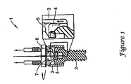
- FIG. 1 illustrates one conventional bone screw arrangement 1 for use with a connecting rod 7.
- the arrangement 1 includes an anchor 2, a yoke member 3, and an internal locking piece 4.
- the internal locking piece 4 has an outer tapered surface, and is positioned within a correspondingly tapered bore 5 of the yoke member 3.
- the connecting rod 7 is aligned with the yoke member 3 for placement of the connecting rod within the saddle of the yoke member 3. Because connecting rods are often times bent to correspond to the curvature of the patent's spinal structure, positioning the connecting rod within the saddle of the yoke member can be difficult.
- a lock nut 6 is tightened down onto the yoke member 3.
- the lock nut 6 forces the connecting rod 7 into the saddle of the yoke member 3 and against the top of the locking piece 4, while at the same time, drawing the yoke member 3 upwardly relative to the locking piece 4 (see relative motion represented by arrows in the enlarged detail view).
- the lock nut 6 draws the yoke member 3 upward, and forces the connecting rod 7 downward, the tapered arrangement of the yoke member 3 and the internal locking piece 4 causes the locking piece 4 to compress radially inward.
- Compression of the locking piece 4 causes the locking piece 4 to clamp on the head of the anchor 2 to fix the anchor 2 at a desired angular orientation relative to the yoke member 3. Concurrently, the rod 7 is clamped between the nut 6 and the top of the locking piece 4.
- the size of a bone screw arrangement is an important aspect in minimizing the invasiveness of a surgical stabilization procedure.
- US 5879350 discloses a retainer for use with a bone anchor and a connecting rod, the retainer comprising:
- the present invention provides a retainer in which the at least one flexible element is an integral construction of the body.
- a retainer having a main body and first and second arms extending from the main body.
- the first and second arms define a central axis there between; the central axis being generally perpendicular to a longitudinal axis of the main body.
- the main body also includes a first receiving region located at the first end of the main body, and a second receiving region located at the second end of the main body.
- the first and second arms are configured to permit placement of a connecting rod within the first receiving region at a number of angular orientations relative to the central axis defined by the first and second arms.
- a fixation device including a retainer, an anchor, and a securing member.
- the retainer includes a saddle region located at a first end and a socket located at a second end.
- a flexible intermediate structure is located between the saddle region and the socket.
- a retainer having a first receiving region configured to receive a connecting rod, and a second receiving region configured to receive a bone anchor.
- the first receiving region includes arms that define a central axis extending there between. The arms further defining a center dimension, a first lateral dimension, and a second lateral dimension. The center, first lateral, and second lateral dimensions are transverse to the central axis. The first and second lateral dimensions are greater than the center dimension.
- a bone fixation device including a yoke, a bone anchor, and a plurality of clamping member.
- the yoke has an upper pocket for receiving a connecting rod and a lower socket.
- the bone anchor has a head mounted in the lower socket of the yoke.
- the plurality of clamping members has upper surfaces that define a portion of the upper pocket and lower surfaces that define a portion of the lower socket.
- the clamping members are integrally connected with the yoke at flex locations, and are configured to clamp the head of the bone anchor within the lower socket when the connecting rod is secured within the upper pocket.
- the method includes providing a bone screw arrangement having an anchor and a retainer including an integral locking structure.
- the method further includes positioning the anchor within a socket of the retainer, pivoting the anchor to a selected axial orientation relative to a longitudinal axis of the retainer, and positioning a connecting rod within a saddle region of the retainer at a non-coaxial orientation relative to a central axis of the retainer.
- FIG. 1 is a partial cross-sectional side view of a prior art bone screw arrangement
- FIG. 2 is a perspective view of one embodiment of a bone screw arrangement, according to the principles of the present disclosure
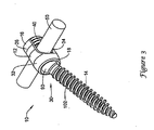
- FIG. 3 is another perspective view of the bone screw arrangement of FIG. 2 ;
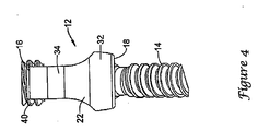
- FIG. 4 is a partial side view of the bone screw arrangement of FIG. 2 ;
- FIG. 5 is a top plan view of one embodiment of a retainer of the bone screw arrangement of FIG. 2 ;
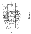
- FIG. 6 is a bottom perspective view of the retainer of FIG. 5 ;
- FIG. 7 is a side perspective view of the retainer of FIG. 5 ;
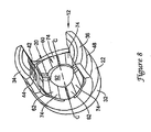
- FIG. 8 is a top perspective view of the retainer of FIG. 5 ;
- FIG. 9 is a top plan view of the retainer of FIG. 5 ;
- FIG. 10 is a top plan view of the retainer of FIG. 9 ;
- FIG. 11 is a side elevational view of the retainer of FIG. 7 ;
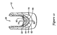
- FIG. 12 is another side perspective view of the retainer of FIG. 11 ;
- FIG. 13 is yet another side perspective view of the retainer of FIG. 12 ;
- FIG. 14 is a side view, shown in partial cross-section, of the bone screw arrangement of FIG. 2 .
- FIGS. 2-14 illustrate a bone screw arrangement 10 in accord with the principles of the present disclosure.
- the bone screw arrangement 10 is designed for use with a connecting rod 50 in spinal stabilization surgeries.
- the bone screw arrangement 10 generally includes a yoke or retainer 12 and a bone anchor 14 (also known as an anchor or pedicle screw).
- the bone screw arrangement 10 is configured to secure each of the retainer 12, the connecting rod 50, and the anchor 14 in a position relative to one another.
- the retainer 12 generally includes a retainer body 22 having a first receiving region 20 located adjacent to a first end 16 of the retainer body 22, and a second receiving region 30 located adjacent to a second end 18 of the retainer body 22.
- the first receiving region 20 also referred to as a saddle or pocket
- the second receiving region 30 is configured to receive a head 90 of the anchor 14.
- the retainer body 22 includes a main body portion 32 and first and second arms 34, 36 that extend outward from the main body portion 32.
- the arms 34, 36 of the retainer body 22 extend parallel with a longitudinal axis A-A ( FIG. 6 ) that runs from the first end 16 of the retainer body 22 to the second end 18 of the retainer body.
- the retainer body 22 also includes intermediate structure 60 ( FIG. 8 ).
- the top side of the intermediate structure 60 and the first and second arms 34, 36 define the first receiving region 20 within which the connecting rod 50 is placed.
- the bottom side of the intermediate structure 60 and the main body portion 32 define the second receiving region 30 within which the head 90 of the anchor 14 is positioned.
- the first and second arms 34, 36 include inner surfaces 44, 46 oriented in an opposed relationship to one another.
- a central axis C-C is defined between the first and second arms 34, 36, and bisects the first receiving region 20.
- the central axis C-C is generally perpendicular to the longitudinal axis A-A of the retainer body 22.
- the inner surfaces 44, 46 of the arms 34, 36 include angled faces 76 ( FIG. 5 ) that extend in a non-parallel direction relative to the central axis C-C of the retainer body 22.
- the angled faces 76 are located on opposite sides 78, 88 of each of the arms. Referring to FIG. 5 , the angled faces 76 have a generally convex construction in relation to the central axis C-C that defines a V-shaped profile.
- the faces 76 of each of the arms 34, 36 meet at an apex portion 81, which is located at a central plane P that bisects the retainer body 22.
- a minimum distance D1 between the inner surfaces 44, 46 of the arms 34, 36 is centrally located between the sides 78, 88 of each of the arms (i.e., the minimum distance D1 is located between the apex portions 81 of the convex constructions of the arms).
- the minimum distance D1 generally corresponds to a diameter of the connecting rod 50.
- a maximum distance D2 between the inner surfaces 44, 46 is defined between edges 79, 89 of the sides 78, 88 of each of the arms 34, 36.
- the maximum distance D2 (due to the angled faces 76) is configured to permit angled placement of the connecting rod 50 within the first region of the retainer body 22.
- the construction of the arms 34, 36 e.g. the minimum distance D1 and the maximum distance D2 can be modified to correspond to varying sizes of connecting rods 50.
- the minimum distance D1 defines a center dimension
- the maximum distance D2 between the edges of each of the arms defines first and second lateral dimensions.
- the center, first lateral and second lateral dimensions are generally perpendicular or transverse to the central axis C-C of the retainer 12.
- the first and second lateral dimensions D2 are greater than the center dimension D 1 to accommodate angled placement of a connecting rod, or to accommodate a connecting rod having a curved configuration.
- the angled faces 76 of the arms 34, 36, and the subsequent dimensional construction of the first receiving region 20 is preferably configured to permit placement of a connecting rod 50 within the first receiving region 20 at a number of angular orientations relative to the central axis C-C of the retainer body 22.
- This arrangement facilitates ease of use of the device during a surgical procedure.
- the connecting rod 50 is positioned within the first receiving region 20 such that the rod is generally coaxially aligned with the central axis C-C of the retainer body 22 (shown in solid line in FIG. 9 ).
- the connecting rod 50 may be angularly oriented such that the rod is angularly offset from, or non-coaxially aligned with the central axis C-C (shown in dashed lines in FIG. 9 ).
- the dimensional construction of the present retainer 12 opens up the area of the first receiving region 20 to permit a user to more easily locate or place a connecting rod 50 within the first receiving region.
- the disclosed arrangement permits a user to more easily place a connecting rod 50 having a curved or bent configuration within the first receiving region 20.
- a bent connecting rod 50 is illustrated in a non-coaxial position within the first receiving region 20.
- the minimum distance D1 of the first receiving region 20 corresponds to the outer diameter of the bent connecting rod, while the maximum distance D2 accommodates the curvature of the bent connecting rod.
- the arms 34, 36 are constructed to accommodate an angular offset A relative to the central axis C-C, in either direction.
- angular offset or “non-coaxially orientation” includes both an offset defined by a straight connecting rod oriented in a non-coaxial or non-parallel orientation relative to the central axis C-C, and an offset or non-coaxial configuration defined by the curvature of a bent connecting rod.
- the angular offset A is preferably between 0 and 20 degrees; more preferably between about 0 and 12 degrees, in either direction relative to the central axis C-C.
- the first receiving region 20 has a range of 0 to 40 degrees (20 degrees in either direction) at which the connecting rod 50 may be oriented when positioned within the first receiving region 20; or more preferably, the first receiving region 20 has a range of about 0 to 24 degrees (12 degrees in either direction) at which the connecting rod 50 may be oriented.
- the first and second arms 34, 36 each include threads 42 that engage a corresponding threaded member 40 ( FIG. 2 ).
- the threads 42 are internal threads formed on the inner surfaces 44, 46 of the arms 34, 36.
- the threaded member 40 is a corresponding set screw or plug that mates with the internal threads to secure the connecting rod 50 within the first receiving region 20 of the retainer 12.
- the threads 42 may be formed on outer surfaces 48 of the arms 34, 36, and the threaded member may include a corresponding threaded nut (not shown).
- the second receiving region 30 is defined within the main body portion 32 of the retainer body 22.
- the second receiving region 30 includes a socket or bore 52 formed at the second end 18 of the retainer body 22.
- the first and second receiving regions 20, 30 are separated by the intermediate structure 60 of the main body portion 32.
- the intermediate structure 60 preferably includes at least one flexible element or clamping member 62.
- the flexible elements 62 are an integral construction of the main body portion 32. This eliminates the assembly costs associated with arrangements having a separate locking piece, such as the arrangement shown in FIG. 1 .
- each of the flexible elements 62 has a free end 70 and a connected end 72.
- the connected end 72 of the element 62 is interconnected to the main body portion 32 of the retainer 12 at a flex location or connection region 66 (see also FIGS. 11 and 12 ).
- the element 62 has a perimeter that is free or non-connected about a majority of the perimeter. That is, the flexible element 62 is spaced apart from the main body portion 32 by a gap 68 along a majority of the perimeter of the element 62. The element is thereby cantilevered from the main body portion 32 of the retainer at the connection region 66. This arrangement permits the elements 62 to flex at the connection regions 66, as will be discussed in greater detail hereinafter.
- the construction of the flexible elements 62 can be manufactured by, for example, an EDM process or other processes capable of creating the flexible configuration of the elements.
- the flexible elements 62 of the intermediate structure 60 each include a top contoured surface 74 that partially defines the first receiving region 20 of the retainer body 22.
- the top contoured surfaces 74 of the elements 62 generally define an overall convex profile along the central axis C-C ( FIG. 13 ).
- the convex profile of the top contoured surfaces 74 aids in centering a connecting rod 50 positioned within the saddle or first receiving region 20 by providing a centered contacting region at which the rod 50 naturally rests.
- the flexible elements 62 include a sloped surface 64 that crests at an opening 92 ( FIGS. 12 and 8 ).
- the opening 92 is defined by a portion of the perimeter of the flexible elements 62.
- the top contoured surface 74 of each of the elements are also scooped. That is, as shown in FIGS. 12 and 13 , the receiving region 20 includes a convex contour that extends along the central axis C-C, and a concave contour that extends traverse to the convex contour (represented by arrows in FIG. 13 ).
- the sloped surfaces 64 and the scooped construction of the elements 62 aid in centering or aligning the connecting rod 50 in relation to the central axis C-C and the longitudinal axis A-A of the retainer 12.
- stops 80 are located within the second receiving region 30 of the retainer body 22.
- two stops 80 are opposingly located within the second receiving region 30.
- the stops 80 are formed on an inner wall 106 of the second receiving region 30 and project toward the center of the second receiving region 30.
- the stops 80 are sized and configured to contact the head 90 of the anchor 14.
- the stops each include at least a first tapered engagement surface 82.
- the tapered engagement surface 82 is configured to contact the head 90 of the anchor 14 to center the head 90 relative to the longitudinal axis A-A of the retainer 12.
- the stops 80 include a stepped construction 83 (seen only on one side in FIG. 6 ) having a second tapered engagement surface 85.
- the stepped construction 83 and second tapered engagement surface 85 similarly guide and center the anchor 14 relative to the longitudinal axis A-A of the retainer body 22.
- the stops 80 are configured to limit the axial location of the anchor 14 when positioned within the socket 52 of the retainer 12.
- the anchor head 90 is positioned within the socket 52 of the second receiving region 30.
- a retaining ring 96 ( FIG. 14 ) is then positioned with a groove 98 formed at the second end 18 of the retainer 12.
- the retaining ring 96 can be welded, bonded, or otherwise permanently or temporarily secured to the retainer 12 to capture the head 90 of the anchor 14 within the second receiving region 30.
- the head 90 of the anchor 14 is generally centered with the socket 52 of the second reviving region 30 by the stops 80 ( FIG. 6 ).
- drive structure 100 is formed within the head 90 of the anchor 14.
- the drive structure 100 may include a hex construction or other type of drive structure.
- a tool couples to the drive structure 100 (shown in FIG. 14 ), which is accessed through the opening 92 ( FIG. 8 ) of the retainer 12, to thread the anchor 14 into bone or other structure of the patient.
- the stops 80 aid in coaxially aligning the drive structure 100 of the anchor 14 in relation to the longitudinal axis A-A of the retainer so that the drive structure 100 of the anchor can be accessed through the opening 92.
- the retainer body 22 can be turned (e.g. swiveled, pivoted or rotated) relative to the anchor 14 to orient the first receiving region for receipt of a connecting rod 50 (see also FIG. 2 ).
- the angled faces 76 of the arms 34, 36 provide a more open, receiving region 20 that accommodates or accepts rods having a bent configuration, or permits a user to position a straight connecting rod at a non-parallel orientation relative to the first and second arms 34, 36.
- the second receiving region 30 is defined by the socket and the flexible elements 62 of the intermediate structure.
- the elements 62 include a bottom contoured surface 75 ( FIG. 6 ) that is generally concave in shape to at least partially define a spherically structured socket 52.
- the spherically structured socket 52 permits the retainer 12 and anchor 14 to freely rotate or swivel relative to one another.
- the retainer 12 can be turned such that a shank 102 of the anchor is positioned relative to the longitudinal axis A-A of the retainer 12 at a desired angular orientation.
- the retainer can be angled at an angle B ( FIG.
- the retainer 12 and the anchor 14 preferably have a universal-type range of motion from one angled position to an opposite angled position of between 0 and 100 degrees; more preferably between 0 and 60 degrees.
- the threaded member 40 is threaded between the arms 34, 36 of the retainer 12. As the threaded member 40 is driven downward along the threads 42 formed on the arms, the connecting rod 50 begins to seat within the first receiving region 20 of the retainer 12. The connecting rod 50 centers within the first receiving region because of the scooped construction and the top contoured surfaces 74 of the flexible elements 62.
- the user continues to assembly the bone screw arrangement by, for example, threading the threaded member 40 against the connecting rod 50 until the member 40 is tightened and fully seated.
- the connecting rod 50 is forced against the flexible elements 62. Because of the flexible configuration of the flexible elements 62, the elements 62 are in turn, biased or forced against the head 90 of the anchor 14. The head 90 of the anchor 14 is thereby captured between the flexible elements 62 and the retaining ring 96 of the retainer 12.
- Each of the retainer 12, the anchor 14, and the connecting rod 50 are now in a fixed position relative to one another.
- the intermediate structure 60 of the retainer eliminates the need for a separate locking piece and generally functions as an integral locking mechanism to secure all of the components in a fixed position relative to one another.
- the overall size and profile of the bone screw arrangement 10 is reduced to minimize the invasiveness of surgical stabilization procedures.
- eliminating the separate locking piece reduces assembly costs, as well as sterilization costs, due to the reduced number of components.
- one embodiment may include the configuration of the first receiving region 20, which permits placement of a connecting rod 50 at a number of non-coaxial orientations, without incorporation of the intermediate structure 60 disclosed.
- another embodiment may include the configuration of the flexible intermediate structure 60 without incorporation of the disclosed first receiving region 20 that permits non-coaxial orientations.
Abstract
Description
- This disclosure relates generally to devices, and associated methods, for stabilizing spinal alignment. More particularly, this disclosure relates to a medical implant, such as a bone screw device configured to receive a connecting rod, and associated methods.
- The human spinal column is prone to diseases or disorders that produce disruption of the normal alignment of the spine. Frequently, treatment of spinal disorders involves spinal stabilization, for example, by immobilization of the affected vertebral joint(s). One spinal stabilization technique includes a surgical process wherein implants are attached to the spinal vertebrae and connected with spinal rods. In particular, a combination of bone screw arrangements and connecting rods are used to provide a stabilizing construct secured to the spinal vertebrae for the purpose of stabilizing and/or adjusting spinal alignment.
-
FIG. 1 illustrates one conventional bone screw arrangement 1 for use with a connectingrod 7. The arrangement 1 includes ananchor 2, ayoke member 3, and an internal locking piece 4. The internal locking piece 4 has an outer tapered surface, and is positioned within a correspondingly tapered bore 5 of theyoke member 3. - In use, the connecting
rod 7 is aligned with theyoke member 3 for placement of the connecting rod within the saddle of theyoke member 3. Because connecting rods are often times bent to correspond to the curvature of the patent's spinal structure, positioning the connecting rod within the saddle of the yoke member can be difficult. - Once the connecting
rod 7 is properly positioned, a lock nut 6 is tightened down onto theyoke member 3. The lock nut 6 forces the connectingrod 7 into the saddle of theyoke member 3 and against the top of the locking piece 4, while at the same time, drawing theyoke member 3 upwardly relative to the locking piece 4 (see relative motion represented by arrows in the enlarged detail view). As the lock nut 6 draws theyoke member 3 upward, and forces the connectingrod 7 downward, the tapered arrangement of theyoke member 3 and the internal locking piece 4 causes the locking piece 4 to compress radially inward. Compression of the locking piece 4 causes the locking piece 4 to clamp on the head of theanchor 2 to fix theanchor 2 at a desired angular orientation relative to theyoke member 3. Concurrently, therod 7 is clamped between the nut 6 and the top of the locking piece 4. - As can be understood, the size of a bone screw arrangement is an important aspect in minimizing the invasiveness of a surgical stabilization procedure. In the arrangement of
FIG. 1 , at least three components: theanchor 2, theyoke member 3, and the locking piece 4, functionally dictate the size of the arrangement. - In general, improvement has been sought with respect to such devices and arrangements, generally to better accommodate: manufacture and assembly, ease of use, reduced invasiveness, and, adaptability for a variety of spinal surgery applications.
US 5879350 discloses a retainer for use with a bone anchor and a connecting rod, the retainer comprising: - a) a body having a longitudinal axis (A-A) defined between a first end and a second end, the body including:
- i) a first receiving region located adjacent to the first end, the first receiving region being configured to receive a connecting rod; and
- ii) a second receiving region located adjacent to the second end, the second receiving region being configured to receive a bone anchor; and
- iii) at least one flexible element positioned between the first receiving region and the second receiving region, the flexible element being configured to flex toward the second receiving region when a connecting rod is secure within the first receiving region.
- The present invention provides a retainer in which the at least one flexible element is an integral construction of the body.
- There is disclosed a retainer having a main body and first and second arms extending from the main body. The first and second arms define a central axis there between; the central axis being generally perpendicular to a longitudinal axis of the main body. The main body also includes a first receiving region located at the first end of the main body, and a second receiving region located at the second end of the main body. The first and second arms are configured to permit placement of a connecting rod within the first receiving region at a number of angular orientations relative to the central axis defined by the first and second arms.
- Also disclosed is a fixation device including a retainer, an anchor, and a securing member. The retainer includes a saddle region located at a first end and a socket located at a second end. A flexible intermediate structure is located between the saddle region and the socket. Each of the retainer, the anchor, and a connecting rod positioned with the saddle region of the retainer are secured in a fixed position relative to one another when the securing member seats the connecting rod within the saddle region.
- Also disclosed is a retainer having a first receiving region configured to receive a connecting rod, and a second receiving region configured to receive a bone anchor. The first receiving region includes arms that define a central axis extending there between. The arms further defining a center dimension, a first lateral dimension, and a second lateral dimension. The center, first lateral, and second lateral dimensions are transverse to the central axis. The first and second lateral dimensions are greater than the center dimension.
- Further disclosed is a bone fixation device including a yoke, a bone anchor, and a plurality of clamping member. The yoke has an upper pocket for receiving a connecting rod and a lower socket. The bone anchor has a head mounted in the lower socket of the yoke. The plurality of clamping members has upper surfaces that define a portion of the upper pocket and lower surfaces that define a portion of the lower socket. The clamping members are integrally connected with the yoke at flex locations, and are configured to clamp the head of the bone anchor within the lower socket when the connecting rod is secured within the upper pocket.
- Also disclosed is a method of using a bone screw arrangement. The method includes providing a bone screw arrangement having an anchor and a retainer including an integral locking structure. The method further includes positioning the anchor within a socket of the retainer, pivoting the anchor to a selected axial orientation relative to a longitudinal axis of the retainer, and positioning a connecting rod within a saddle region of the retainer at a non-coaxial orientation relative to a central axis of the retainer.
- A variety of examples of desirable product features or methods are set forth in part in the description that follows, and in part will be apparent from the description, or may be learned by practicing various aspects of the disclosure. The aspects of the disclosure may relate to individual features as well as combinations of features. It is to be understood that both the foregoing general description and the following detailed description are explanatory only, and are not restrictive of the claimed invention.
-
FIG. 1 is a partial cross-sectional side view of a prior art bone screw arrangement; -
FIG. 2 is a perspective view of one embodiment of a bone screw arrangement, according to the principles of the present disclosure; -
FIG. 3 is another perspective view of the bone screw arrangement ofFIG. 2 ; -
FIG. 4 is a partial side view of the bone screw arrangement ofFIG. 2 ; -
FIG. 5 is a top plan view of one embodiment of a retainer of the bone screw arrangement ofFIG. 2 ; -
FIG. 6 is a bottom perspective view of the retainer ofFIG. 5 ; -
FIG. 7 is a side perspective view of the retainer ofFIG. 5 ; -
FIG. 8 is a top perspective view of the retainer ofFIG. 5 ; -
FIG. 9 is a top plan view of the retainer ofFIG. 5 ; -
FIG. 10 is a top plan view of the retainer ofFIG. 9 ; -
FIG. 11 is a side elevational view of the retainer ofFIG. 7 ; -
FIG. 12 is another side perspective view of the retainer ofFIG. 11 ; -
FIG. 13 is yet another side perspective view of the retainer ofFIG. 12 ; and -
FIG. 14 is a side view, shown in partial cross-section, of the bone screw arrangement ofFIG. 2 . - Reference will now be made in detail to various features of the present disclosure that are illustrated in the accompanying drawings. Wherever possible, the same reference numbers will be used throughout the drawings to refer to the same or like parts.
-
FIGS. 2-14 illustrate abone screw arrangement 10 in accord with the principles of the present disclosure. Thebone screw arrangement 10 is designed for use with a connectingrod 50 in spinal stabilization surgeries. Thebone screw arrangement 10 generally includes a yoke orretainer 12 and a bone anchor 14 (also known as an anchor or pedicle screw). Thebone screw arrangement 10 is configured to secure each of theretainer 12, the connectingrod 50, and theanchor 14 in a position relative to one another. - Referring to
FIGS. 2-4 , theretainer 12 generally includes aretainer body 22 having a first receivingregion 20 located adjacent to afirst end 16 of theretainer body 22, and asecond receiving region 30 located adjacent to asecond end 18 of theretainer body 22. The first receiving region 20 (also referred to as a saddle or pocket) is configured to receive a connectingrod 50. Thesecond receiving region 30 is configured to receive ahead 90 of theanchor 14. In the illustrated embodiment, theretainer body 22 includes amain body portion 32 and first andsecond arms main body portion 32. - Referring now to
FIGS. 5-8 , thearms retainer body 22 extend parallel with a longitudinal axis A-A (FIG. 6 ) that runs from thefirst end 16 of theretainer body 22 to thesecond end 18 of the retainer body. Theretainer body 22 also includes intermediate structure 60 (FIG. 8 ). The top side of theintermediate structure 60 and the first andsecond arms region 20 within which the connectingrod 50 is placed. The bottom side of theintermediate structure 60 and themain body portion 32 define the second receivingregion 30 within which thehead 90 of theanchor 14 is positioned. - As shown in
FIGS. 5 and8 , the first andsecond arms inner surfaces second arms region 20. The central axis C-C is generally perpendicular to the longitudinal axis A-A of theretainer body 22. - The
inner surfaces arms FIG. 5 ) that extend in a non-parallel direction relative to the central axis C-C of theretainer body 22. The angled faces 76 are located onopposite sides FIG. 5 , the angled faces 76 have a generally convex construction in relation to the central axis C-C that defines a V-shaped profile. The faces 76 of each of thearms apex portion 81, which is located at a central plane P that bisects theretainer body 22. - Referring now to
FIG. 9 , a minimum distance D1 between theinner surfaces arms sides apex portions 81 of the convex constructions of the arms). The minimum distance D1 generally corresponds to a diameter of the connectingrod 50. A maximum distance D2 between theinner surfaces edges sides arms rod 50 within the first region of theretainer body 22. As can be understood, the construction of thearms 34, 36 (e.g. the minimum distance D1 and the maximum distance D2) can be modified to correspond to varying sizes of connectingrods 50. - In the illustrated embodiment, the minimum distance D1 defines a center dimension, and the maximum distance D2 between the edges of each of the arms defines first and second lateral dimensions. The center, first lateral and second lateral dimensions are generally perpendicular or transverse to the central axis C-C of the
retainer 12. Preferably, the first and second lateral dimensions D2 are greater than the center dimension D 1 to accommodate angled placement of a connecting rod, or to accommodate a connecting rod having a curved configuration. - In particular, the angled faces 76 of the
arms region 20, is preferably configured to permit placement of a connectingrod 50 within the first receivingregion 20 at a number of angular orientations relative to the central axis C-C of theretainer body 22. This arrangement facilitates ease of use of the device during a surgical procedure. For example, in some applications, the connectingrod 50 is positioned within the first receivingregion 20 such that the rod is generally coaxially aligned with the central axis C-C of the retainer body 22 (shown in solid line inFIG. 9 ). In an alternative application, the connectingrod 50 may be angularly oriented such that the rod is angularly offset from, or non-coaxially aligned with the central axis C-C (shown in dashed lines inFIG. 9 ). The dimensional construction of thepresent retainer 12 opens up the area of the first receivingregion 20 to permit a user to more easily locate or place a connectingrod 50 within the first receiving region. - In addition, the disclosed arrangement permits a user to more easily place a connecting
rod 50 having a curved or bent configuration within the first receivingregion 20. Referring toFIG. 10 , a bent connectingrod 50 is illustrated in a non-coaxial position within the first receivingregion 20. The minimum distance D1 of the first receivingregion 20 corresponds to the outer diameter of the bent connecting rod, while the maximum distance D2 accommodates the curvature of the bent connecting rod. - Referring back to
FIG. 9 , preferably, thearms region 20 has a range of 0 to 40 degrees (20 degrees in either direction) at which the connectingrod 50 may be oriented when positioned within the first receivingregion 20; or more preferably, the first receivingregion 20 has a range of about 0 to 24 degrees (12 degrees in either direction) at which the connectingrod 50 may be oriented. - Referring back now to
FIGS. 7 and8 , the first andsecond arms threads 42 that engage a corresponding threaded member 40 (FIG. 2 ). In the illustrated embodiment, thethreads 42 are internal threads formed on theinner surfaces arms member 40 is a corresponding set screw or plug that mates with the internal threads to secure the connectingrod 50 within the first receivingregion 20 of theretainer 12. In an alternative embodiment, thethreads 42 may be formed onouter surfaces 48 of thearms - Referring again to
FIGS. 6-7 , the second receivingregion 30 is defined within themain body portion 32 of theretainer body 22. Thesecond receiving region 30 includes a socket or bore 52 formed at thesecond end 18 of theretainer body 22. The first and second receivingregions intermediate structure 60 of themain body portion 32. - The
intermediate structure 60 preferably includes at least one flexible element or clampingmember 62. In the illustrated embodiment, four flexible elements are provided, although any number of elements can be provided in accord with the principles disclosed. According to the invention, theflexible elements 62 are an integral construction of themain body portion 32. This eliminates the assembly costs associated with arrangements having a separate locking piece, such as the arrangement shown inFIG. 1 . - Referring to
FIG. 5 , each of theflexible elements 62 has afree end 70 and a connected end 72. The connected end 72 of theelement 62 is interconnected to themain body portion 32 of theretainer 12 at a flex location or connection region 66 (see alsoFIGS. 11 and12 ). In the illustrated embodiment, theelement 62 has a perimeter that is free or non-connected about a majority of the perimeter. That is, theflexible element 62 is spaced apart from themain body portion 32 by agap 68 along a majority of the perimeter of theelement 62. The element is thereby cantilevered from themain body portion 32 of the retainer at theconnection region 66. This arrangement permits theelements 62 to flex at theconnection regions 66, as will be discussed in greater detail hereinafter. The construction of theflexible elements 62 can be manufactured by, for example, an EDM process or other processes capable of creating the flexible configuration of the elements. - Referring now to
FIGS. 8 and11-13 , theflexible elements 62 of theintermediate structure 60 each include a top contouredsurface 74 that partially defines the first receivingregion 20 of theretainer body 22. In the illustrated embodiment, the topcontoured surfaces 74 of theelements 62 generally define an overall convex profile along the central axis C-C (FIG. 13 ). The convex profile of the topcontoured surfaces 74 aids in centering a connectingrod 50 positioned within the saddle or first receivingregion 20 by providing a centered contacting region at which therod 50 naturally rests. - More specifically, the
flexible elements 62 include asloped surface 64 that crests at an opening 92 (FIGS. 12 and8 ). Theopening 92 is defined by a portion of the perimeter of theflexible elements 62. At the same time, the top contouredsurface 74 of each of the elements are also scooped. That is, as shown inFIGS. 12 and13 , the receivingregion 20 includes a convex contour that extends along the central axis C-C, and a concave contour that extends traverse to the convex contour (represented by arrows inFIG. 13 ). The sloped surfaces 64 and the scooped construction of theelements 62 aid in centering or aligning the connectingrod 50 in relation to the central axis C-C and the longitudinal axis A-A of theretainer 12. - Referring again to
FIG. 6 , stops 80 are located within the second receivingregion 30 of theretainer body 22. In the illustrated embodiment, twostops 80 are opposingly located within the second receivingregion 30. The stops 80 are formed on aninner wall 106 of the second receivingregion 30 and project toward the center of the second receivingregion 30. The stops 80 are sized and configured to contact thehead 90 of theanchor 14. The stops each include at least a firsttapered engagement surface 82. The taperedengagement surface 82 is configured to contact thehead 90 of theanchor 14 to center thehead 90 relative to the longitudinal axis A-A of theretainer 12. In the illustrated embodiment, thestops 80 include a stepped construction 83 (seen only on one side inFIG. 6 ) having a second tapered engagement surface 85. The steppedconstruction 83 and second tapered engagement surface 85 similarly guide and center theanchor 14 relative to the longitudinal axis A-A of theretainer body 22. - The stops 80 are configured to limit the axial location of the
anchor 14 when positioned within thesocket 52 of theretainer 12. During assembly of thebone screw arrangement 10, theanchor head 90 is positioned within thesocket 52 of the second receivingregion 30. A retaining ring 96 (FIG. 14 ) is then positioned with agroove 98 formed at thesecond end 18 of theretainer 12. The retainingring 96 can be welded, bonded, or otherwise permanently or temporarily secured to theretainer 12 to capture thehead 90 of theanchor 14 within the second receivingregion 30. - Referring now to
FIG. 14 , thehead 90 of theanchor 14 is generally centered with thesocket 52 of the second revivingregion 30 by the stops 80 (FIG. 6 ). In the illustrated embodiment,drive structure 100 is formed within thehead 90 of theanchor 14. Thedrive structure 100 may include a hex construction or other type of drive structure. In use, a tool (not shown) couples to the drive structure 100 (shown inFIG. 14 ), which is accessed through the opening 92 (FIG. 8 ) of theretainer 12, to thread theanchor 14 into bone or other structure of the patient. The stops 80 aid in coaxially aligning thedrive structure 100 of theanchor 14 in relation to the longitudinal axis A-A of the retainer so that thedrive structure 100 of the anchor can be accessed through theopening 92. Once theanchor 14 is positioned and secured as needed, the tool is removed from thedrive structure 100 of theanchor 14 and theretainer 12 can be turned to a desired orientation to receive a connectingrod 50. - In particular, the
retainer body 22 can be turned (e.g. swiveled, pivoted or rotated) relative to theanchor 14 to orient the first receiving region for receipt of a connecting rod 50 (see alsoFIG. 2 ). The angled faces 76 of thearms region 20 that accommodates or accepts rods having a bent configuration, or permits a user to position a straight connecting rod at a non-parallel orientation relative to the first andsecond arms - In the illustrated embodiment, the second receiving
region 30 is defined by the socket and theflexible elements 62 of the intermediate structure. Theelements 62 include a bottom contoured surface 75 (FIG. 6 ) that is generally concave in shape to at least partially define a spherically structuredsocket 52. The spherically structuredsocket 52 permits theretainer 12 andanchor 14 to freely rotate or swivel relative to one another. When theanchor 14 is secured to a structure of a patient, theretainer 12 can be turned such that ashank 102 of the anchor is positioned relative to the longitudinal axis A-A of theretainer 12 at a desired angular orientation. Preferably, the retainer can be angled at an angle B (FIG. 14 ) of between 0 and 50 degrees relative to the longitudinal axis A-A of theretainer 12, in any direction; more preferably between 0 and 30 degrees, in any direction. In other words, theretainer 12 and theanchor 14 preferably have a universal-type range of motion from one angled position to an opposite angled position of between 0 and 100 degrees; more preferably between 0 and 60 degrees. - After the connecting rod has been placed within the first receiving
region 20, the threadedmember 40 is threaded between thearms retainer 12. As the threadedmember 40 is driven downward along thethreads 42 formed on the arms, the connectingrod 50 begins to seat within the first receivingregion 20 of theretainer 12. The connectingrod 50 centers within the first receiving region because of the scooped construction and the topcontoured surfaces 74 of theflexible elements 62. - To lock all of the components (i.e. the
retainer 12, theanchor 14, and the connecting rod 50) relative to one another, the user continues to assembly the bone screw arrangement by, for example, threading the threadedmember 40 against the connectingrod 50 until themember 40 is tightened and fully seated. As the threadedmember 40 is being tightened, the connectingrod 50 is forced against theflexible elements 62. Because of the flexible configuration of theflexible elements 62, theelements 62 are in turn, biased or forced against thehead 90 of theanchor 14. Thehead 90 of theanchor 14 is thereby captured between theflexible elements 62 and the retainingring 96 of theretainer 12. Each of theretainer 12, theanchor 14, and the connectingrod 50 are now in a fixed position relative to one another. - The
intermediate structure 60 of the retainer eliminates the need for a separate locking piece and generally functions as an integral locking mechanism to secure all of the components in a fixed position relative to one another. By eliminating the need for a separate locking piece, the overall size and profile of thebone screw arrangement 10 is reduced to minimize the invasiveness of surgical stabilization procedures. Also, eliminating the separate locking piece reduces assembly costs, as well as sterilization costs, due to the reduced number of components. - It is to be understood that one embodiment may include the configuration of the first receiving
region 20, which permits placement of a connectingrod 50 at a number of non-coaxial orientations, without incorporation of theintermediate structure 60 disclosed. Likewise, another embodiment may include the configuration of the flexibleintermediate structure 60 without incorporation of the disclosed first receivingregion 20 that permits non-coaxial orientations.
Claims (20)
- A retainer (12) for use with a bone anchor (14) and a connecting rod (50), the retainer (12) comprising:a) a body (22) having a longitudinal axis (A-A) defined between a first end (16) and a second end (18), the body (22) including:i) a first receiving region (20) located adjacent to the first end (16), the first receiving region (20) being configured to receive a connecting rod (50); andii) a second receiving region (30) located adjacent to the second end (18), the second receiving region (30) being configured to receive a bone anchor (14); andiii) at least one flexible element (62) positioned between the first receiving region (20) and the second receiving region (30), the flexible element (62) being configured to flex toward the second receiving region (30) when a connecting rod (50) is secure within the first receiving region (20), characterized in that the at least one flexible element (62) is an integral construction of the body (22).
- The retainer of claim 1, wherein the first receiving region (20) is partially defined by arms (34, 36) extending outward from a main portion (32) of the body (22).
- The retainer of claim 2, wherein the arms (34, 36) include threads (42) for receipt of a mating threaded member (40) to secure a connecting rod (50) positioned within the first receiving region (20).
- The retainer of claim 3, wherein the threads (42) are internal threads.
- The retainer of either claim 3, wherein the mating threaded member (40) is a set screw.
- The retainer of claim 2, wherein the second receiving region (30) is defined within the main portion (32) of the body (22).
- The retainer of any preceding claim, wherein the body (22) further includes a plurality of flexible elements (62) positioned between the first and second receiving regions (20, 30) of the body (22).
- The retainer of claim 7, wherein the first receiving region (20) of the body (22) has a convex contour and a traverse concave contour defined by the plurality of flexible elements (62).
- The retainer of any preceding claim, wherein the flexible element (62) has a perimeter that is non-connected to a main portion (32) of the body (22) along a majority of the perimeter of the flexible element (62).
- The retainer of any preceding claim, wherein the flexible element (62) is interconnected to the body (22) such that the flexible element (62) is cantilevered.
- The retainer of any preceding claim, wherein the body (22) further includes structure (80) formed on an inner surface (106) of the second receiving region (30) that centers the bone anchor (14) relative to the longitudinal axis (A-A) of the body (22).
- A bone fixation device, comprising:a) the retainer (12) of claim 1;b) an anchor (14) positioned within the second receiving region (30) of the retainer (12); andc) a securing member (40) positionable within the first receiving region (20) of the retainer (12) to secure a connecting rod (50) positioned within the first receiving region (20);d) wherein each of the retainer (12), the anchor (14), and a connecting rod (50) positioned with the first receiving region (20) of the retainer (12) are secured in a fixed position relative to one another when the securing member (40) seats the connecting rod (50) within the first receiving region (20).
- The device of claim 12, wherein the at least one flexible element (62) defines an opening (92) to access drive structure (100) of the anchor (14).
- The device of either claim 12 or claim 13, wherein the first receiving region (20) is defined by arms (34, 36) extending from a main body portion (32) of the retainer (12).
- The device of claim 14, wherein the securing member (40) includes a set screw that forces a connecting rod (50) positioned within the first receiving region (20) against the at least one flexible element (62).
- The device of claim 14, wherein the first and second arms (34, 36) of the first receiving region (20) are configured to receive a connecting rod (50) in a number of angular orientations relative to the first and second arms (34, 36).
- The device of any one of claims 12 to 16, wherein the retainer (12) includes a plurality of flexible elements (62).
- The device of claim 17, wherein each of the flexible elements (62) is an integral construction of a main body portion (32) of the retainer (12).
- The device of claim 17, wherein each of the flexible elements (62) has a perimeter that is non-connected to a main body portion (32) of the retainer (12) along a majority of the perimeter of the flexible element (62).
- The device of any one of claims 12 to 19, further including a retaining ring (96) to retain the anchor (14) within the second receiving region (30) of the retainer (12).
Applications Claiming Priority (2)
| Application Number | Priority Date | Filing Date | Title |
|---|---|---|---|
| US10/865,672 US7935135B2 (en) | 2004-06-09 | 2004-06-09 | Spinal fixation device |
| PCT/US2005/020609 WO2005122928A2 (en) | 2004-06-09 | 2005-06-09 | Spinal fixation device |
Publications (2)
| Publication Number | Publication Date |
|---|---|
| EP1755472A2 EP1755472A2 (en) | 2007-02-28 |
| EP1755472B1 true EP1755472B1 (en) | 2011-10-05 |
Family
ID=35044783
Family Applications (1)
| Application Number | Title | Priority Date | Filing Date |
|---|---|---|---|
| EP05760406A Not-in-force EP1755472B1 (en) | 2004-06-09 | 2005-06-09 | Spinal fixation device |
Country Status (4)
| Country | Link |
|---|---|
| US (1) | US7935135B2 (en) |
| EP (1) | EP1755472B1 (en) |
| AT (1) | ATE526892T1 (en) |
| WO (1) | WO2005122928A2 (en) |
Families Citing this family (139)
| Publication number | Priority date | Publication date | Assignee | Title |
|---|---|---|---|---|
| US7833250B2 (en) | 2004-11-10 | 2010-11-16 | Jackson Roger P | Polyaxial bone screw with helically wound capture connection |
| US8377100B2 (en) | 2000-12-08 | 2013-02-19 | Roger P. Jackson | Closure for open-headed medical implant |
| US8353932B2 (en) | 2005-09-30 | 2013-01-15 | Jackson Roger P | Polyaxial bone anchor assembly with one-piece closure, pressure insert and plastic elongate member |
| US8292926B2 (en) | 2005-09-30 | 2012-10-23 | Jackson Roger P | Dynamic stabilization connecting member with elastic core and outer sleeve |
| US10729469B2 (en) | 2006-01-09 | 2020-08-04 | Roger P. Jackson | Flexible spinal stabilization assembly with spacer having off-axis core member |
| US10258382B2 (en) | 2007-01-18 | 2019-04-16 | Roger P. Jackson | Rod-cord dynamic connection assemblies with slidable bone anchor attachment members along the cord |
| US7862587B2 (en) | 2004-02-27 | 2011-01-04 | Jackson Roger P | Dynamic stabilization assemblies, tool set and method |
| US6740086B2 (en) * | 2002-04-18 | 2004-05-25 | Spinal Innovations, Llc | Screw and rod fixation assembly and device |
| US11224464B2 (en) | 2002-05-09 | 2022-01-18 | Roger P. Jackson | Threaded closure with inwardly-facing tool engaging concave radiused structures and axial through-aperture |
| US8876868B2 (en) | 2002-09-06 | 2014-11-04 | Roger P. Jackson | Helical guide and advancement flange with radially loaded lip |
| US8523913B2 (en) | 2002-09-06 | 2013-09-03 | Roger P. Jackson | Helical guide and advancement flange with break-off extensions |
| US6716214B1 (en) | 2003-06-18 | 2004-04-06 | Roger P. Jackson | Polyaxial bone screw with spline capture connection |
| US7621918B2 (en) | 2004-11-23 | 2009-11-24 | Jackson Roger P | Spinal fixation tool set and method |
| US7377923B2 (en) | 2003-05-22 | 2008-05-27 | Alphatec Spine, Inc. | Variable angle spinal screw assembly |
| US8814911B2 (en) | 2003-06-18 | 2014-08-26 | Roger P. Jackson | Polyaxial bone screw with cam connection and lock and release insert |
| US8257398B2 (en) | 2003-06-18 | 2012-09-04 | Jackson Roger P | Polyaxial bone screw with cam capture |
| US7967850B2 (en) | 2003-06-18 | 2011-06-28 | Jackson Roger P | Polyaxial bone anchor with helical capture connection, insert and dual locking assembly |
| US8398682B2 (en) | 2003-06-18 | 2013-03-19 | Roger P. Jackson | Polyaxial bone screw assembly |
| US7776067B2 (en) | 2005-05-27 | 2010-08-17 | Jackson Roger P | Polyaxial bone screw with shank articulation pressure insert and method |
| US8377102B2 (en) | 2003-06-18 | 2013-02-19 | Roger P. Jackson | Polyaxial bone anchor with spline capture connection and lower pressure insert |
| US8936623B2 (en) | 2003-06-18 | 2015-01-20 | Roger P. Jackson | Polyaxial bone screw assembly |
| US8137386B2 (en) | 2003-08-28 | 2012-03-20 | Jackson Roger P | Polyaxial bone screw apparatus |
| US7766915B2 (en) | 2004-02-27 | 2010-08-03 | Jackson Roger P | Dynamic fixation assemblies with inner core and outer coil-like member |
| US7967826B2 (en) * | 2003-10-21 | 2011-06-28 | Theken Spine, Llc | Connector transfer tool for internal structure stabilization systems |
| US7588575B2 (en) | 2003-10-21 | 2009-09-15 | Innovative Spinal Technologies | Extension for use with stabilization systems for internal structures |
| US11419642B2 (en) | 2003-12-16 | 2022-08-23 | Medos International Sarl | Percutaneous access devices and bone anchor assemblies |
| US7527638B2 (en) | 2003-12-16 | 2009-05-05 | Depuy Spine, Inc. | Methods and devices for minimally invasive spinal fixation element placement |
| US7179261B2 (en) | 2003-12-16 | 2007-02-20 | Depuy Spine, Inc. | Percutaneous access devices and bone anchor assemblies |
| US8152810B2 (en) | 2004-11-23 | 2012-04-10 | Jackson Roger P | Spinal fixation tool set and method |
| CA2555868C (en) | 2004-02-27 | 2011-09-06 | Roger P. Jackson | Orthopedic implant rod reduction tool set and method |
| US9050148B2 (en) | 2004-02-27 | 2015-06-09 | Roger P. Jackson | Spinal fixation tool attachment structure |
| US7160300B2 (en) | 2004-02-27 | 2007-01-09 | Jackson Roger P | Orthopedic implant rod reduction tool set and method |
| US11241261B2 (en) | 2005-09-30 | 2022-02-08 | Roger P Jackson | Apparatus and method for soft spinal stabilization using a tensionable cord and releasable end structure |
| US8475495B2 (en) | 2004-04-08 | 2013-07-02 | Globus Medical | Polyaxial screw |
| US7503924B2 (en) | 2004-04-08 | 2009-03-17 | Globus Medical, Inc. | Polyaxial screw |
| US7857834B2 (en) * | 2004-06-14 | 2010-12-28 | Zimmer Spine, Inc. | Spinal implant fixation assembly |
| US7651502B2 (en) | 2004-09-24 | 2010-01-26 | Jackson Roger P | Spinal fixation tool set and method for rod reduction and fastener insertion |
| US8926672B2 (en) | 2004-11-10 | 2015-01-06 | Roger P. Jackson | Splay control closure for open bone anchor |
| US8556938B2 (en) | 2009-06-15 | 2013-10-15 | Roger P. Jackson | Polyaxial bone anchor with non-pivotable retainer and pop-on shank, some with friction fit |
| US9168069B2 (en) | 2009-06-15 | 2015-10-27 | Roger P. Jackson | Polyaxial bone anchor with pop-on shank and winged insert with lower skirt for engaging a friction fit retainer |
| US8444681B2 (en) | 2009-06-15 | 2013-05-21 | Roger P. Jackson | Polyaxial bone anchor with pop-on shank, friction fit retainer and winged insert |
| US9980753B2 (en) | 2009-06-15 | 2018-05-29 | Roger P Jackson | pivotal anchor with snap-in-place insert having rotation blocking extensions |
| US9216041B2 (en) | 2009-06-15 | 2015-12-22 | Roger P. Jackson | Spinal connecting members with tensioned cords and rigid sleeves for engaging compression inserts |
| US7875065B2 (en) | 2004-11-23 | 2011-01-25 | Jackson Roger P | Polyaxial bone screw with multi-part shank retainer and pressure insert |
| US8308782B2 (en) | 2004-11-23 | 2012-11-13 | Jackson Roger P | Bone anchors with longitudinal connecting member engaging inserts and closures for fixation and optional angulation |
| ATE524121T1 (en) | 2004-11-24 | 2011-09-15 | Abdou Samy | DEVICES FOR PLACING AN ORTHOPEDIC INTERVERTEBRAL IMPLANT |
| US7901437B2 (en) | 2007-01-26 | 2011-03-08 | Jackson Roger P | Dynamic stabilization member with molded connection |
| US10076361B2 (en) | 2005-02-22 | 2018-09-18 | Roger P. Jackson | Polyaxial bone screw with spherical capture, compression and alignment and retention structures |
| US7951198B2 (en) * | 2005-05-10 | 2011-05-31 | Acumed Llc | Bone connector with pivotable joint |
| US8105368B2 (en) | 2005-09-30 | 2012-01-31 | Jackson Roger P | Dynamic stabilization connecting member with slitted core and outer sleeve |
| US8100946B2 (en) | 2005-11-21 | 2012-01-24 | Synthes Usa, Llc | Polyaxial bone anchors with increased angulation |
| US7704271B2 (en) | 2005-12-19 | 2010-04-27 | Abdou M Samy | Devices and methods for inter-vertebral orthopedic device placement |
| CA2647026A1 (en) | 2006-03-22 | 2008-08-28 | Pioneer Surgical Technology, Inc. | Low top bone fixation system and method for using the same |
| US8172882B2 (en) | 2006-06-14 | 2012-05-08 | Spartek Medical, Inc. | Implant system and method to treat degenerative disorders of the spine |
| US8062340B2 (en) * | 2006-08-16 | 2011-11-22 | Pioneer Surgical Technology, Inc. | Spinal rod anchor device and method |
| US7967821B2 (en) | 2006-11-20 | 2011-06-28 | Depuy Spine, Inc. | Break-off screw extension removal tools |
| CA2670988C (en) | 2006-12-08 | 2014-03-25 | Roger P. Jackson | Tool system for dynamic spinal implants |
| US8475498B2 (en) | 2007-01-18 | 2013-07-02 | Roger P. Jackson | Dynamic stabilization connecting member with cord connection |
| US8366745B2 (en) | 2007-05-01 | 2013-02-05 | Jackson Roger P | Dynamic stabilization assembly having pre-compressed spacers with differential displacements |
| US7959655B2 (en) * | 2007-03-06 | 2011-06-14 | Warsaw Orthopedic, Inc. | Self-aligning attachment devices and methods for attaching an elongated member to a vertebral member |
| US10383660B2 (en) | 2007-05-01 | 2019-08-20 | Roger P. Jackson | Soft stabilization assemblies with pretensioned cords |
| US7963978B2 (en) | 2007-06-05 | 2011-06-21 | Spartek Medical, Inc. | Method for implanting a deflection rod system and customizing the deflection rod system for a particular patient need for dynamic stabilization and motion preservation spinal implantation system |
| US8083772B2 (en) | 2007-06-05 | 2011-12-27 | Spartek Medical, Inc. | Dynamic spinal rod assembly and method for dynamic stabilization of the spine |
| US8048122B2 (en) | 2007-06-05 | 2011-11-01 | Spartek Medical, Inc. | Spine implant with a dual deflection rod system including a deflection limiting sheild associated with a bone screw and method |
| US8048115B2 (en) | 2007-06-05 | 2011-11-01 | Spartek Medical, Inc. | Surgical tool and method for implantation of a dynamic bone anchor |
| US8092501B2 (en) | 2007-06-05 | 2012-01-10 | Spartek Medical, Inc. | Dynamic spinal rod and method for dynamic stabilization of the spine |
| US8002800B2 (en) | 2007-06-05 | 2011-08-23 | Spartek Medical, Inc. | Horizontal rod with a mounting platform for a dynamic stabilization and motion preservation spinal implantation system and method |
| WO2008154194A1 (en) * | 2007-06-05 | 2008-12-18 | Spartek Medical, Inc. | Dynamic stabilization and motion preservation spinal implantation system and method |
| US8114134B2 (en) | 2007-06-05 | 2012-02-14 | Spartek Medical, Inc. | Spinal prosthesis having a three bar linkage for motion preservation and dynamic stabilization of the spine |
| WO2008151096A1 (en) | 2007-06-05 | 2008-12-11 | Spartek Medical, Inc. | A deflection rod system for a dynamic stabilization and motion preservation spinal implantation system and method |
| US8021396B2 (en) | 2007-06-05 | 2011-09-20 | Spartek Medical, Inc. | Configurable dynamic spinal rod and method for dynamic stabilization of the spine |
| US9439681B2 (en) | 2007-07-20 | 2016-09-13 | DePuy Synthes Products, Inc. | Polyaxial bone fixation element |
| PL2170192T3 (en) * | 2007-07-20 | 2011-07-29 | Synthes Gmbh | Polyaxial bone fixation element |
| WO2009014540A1 (en) * | 2007-07-26 | 2009-01-29 | Biotechni America Spine Group Inc. | Spinal fixation assembly |
| US8414588B2 (en) | 2007-10-04 | 2013-04-09 | Depuy Spine, Inc. | Methods and devices for minimally invasive spinal connection element delivery |
| US8398683B2 (en) * | 2007-10-23 | 2013-03-19 | Pioneer Surgical Technology, Inc. | Rod coupling assembly and methods for bone fixation |
| US8211155B2 (en) | 2008-02-26 | 2012-07-03 | Spartek Medical, Inc. | Load-sharing bone anchor having a durable compliant member and method for dynamic stabilization of the spine |
| US8057517B2 (en) | 2008-02-26 | 2011-11-15 | Spartek Medical, Inc. | Load-sharing component having a deflectable post and centering spring and method for dynamic stabilization of the spine |
| US20100030224A1 (en) | 2008-02-26 | 2010-02-04 | Spartek Medical, Inc. | Surgical tool and method for connecting a dynamic bone anchor and dynamic vertical rod |
| US8267979B2 (en) | 2008-02-26 | 2012-09-18 | Spartek Medical, Inc. | Load-sharing bone anchor having a deflectable post and axial spring and method for dynamic stabilization of the spine |
| US8097024B2 (en) | 2008-02-26 | 2012-01-17 | Spartek Medical, Inc. | Load-sharing bone anchor having a deflectable post and method for stabilization of the spine |
| US8048125B2 (en) | 2008-02-26 | 2011-11-01 | Spartek Medical, Inc. | Versatile offset polyaxial connector and method for dynamic stabilization of the spine |
| US8337536B2 (en) | 2008-02-26 | 2012-12-25 | Spartek Medical, Inc. | Load-sharing bone anchor having a deflectable post with a compliant ring and method for stabilization of the spine |
| US8083775B2 (en) | 2008-02-26 | 2011-12-27 | Spartek Medical, Inc. | Load-sharing bone anchor having a natural center of rotation and method for dynamic stabilization of the spine |
| US8333792B2 (en) | 2008-02-26 | 2012-12-18 | Spartek Medical, Inc. | Load-sharing bone anchor having a deflectable post and method for dynamic stabilization of the spine |
| US20090264933A1 (en) * | 2008-04-22 | 2009-10-22 | Warsaw Orthopedic, Inc. | Anchors for securing a rod to a vertebral member |
| WO2009155523A1 (en) * | 2008-06-19 | 2009-12-23 | Life Spine, Inc. | Spinal rod connectors configured to retain spinal rods of varying diameters |
| US8197512B1 (en) | 2008-07-16 | 2012-06-12 | Zimmer Spine, Inc. | System and method for spine stabilization using resilient inserts |
| GB0813659D0 (en) | 2008-07-25 | 2008-09-03 | Smith & Nephew | Fracture putty |
| CA2739997C (en) | 2008-08-01 | 2013-08-13 | Roger P. Jackson | Longitudinal connecting member with sleeved tensioned cords |
| US8870924B2 (en) | 2008-09-04 | 2014-10-28 | Zimmer Spine, Inc. | Dynamic vertebral fastener |
| WO2010028287A2 (en) | 2008-09-05 | 2010-03-11 | Synthes Usa, Llc | Bone fixation assembly |
| JP5815407B2 (en) | 2008-09-12 | 2015-11-17 | ジンテス ゲゼルシャフト ミット ベシュレンクテル ハフツング | Spinal stabilization and guided fixation system |
| EP2339975B1 (en) | 2008-09-29 | 2015-03-25 | Synthes GmbH | Polyaxial bottom-loading screw and rod assembly |
| US8506601B2 (en) * | 2008-10-14 | 2013-08-13 | Pioneer Surgical Technology, Inc. | Low profile dual locking fixation system and offset anchor member |
| US8628558B2 (en) | 2008-11-03 | 2014-01-14 | DePuy Synthes Products, LLC | Uni-planer bone fixation assembly |
| US8043338B2 (en) * | 2008-12-03 | 2011-10-25 | Zimmer Spine, Inc. | Adjustable assembly for correcting spinal abnormalities |
| US8636778B2 (en) * | 2009-02-11 | 2014-01-28 | Pioneer Surgical Technology, Inc. | Wide angulation coupling members for bone fixation system |
| CA2758590A1 (en) | 2009-04-15 | 2010-10-21 | Synthes Usa, Llc | Revision connector for spinal constructs |
| US8998959B2 (en) | 2009-06-15 | 2015-04-07 | Roger P Jackson | Polyaxial bone anchors with pop-on shank, fully constrained friction fit retainer and lock and release insert |
| US11229457B2 (en) | 2009-06-15 | 2022-01-25 | Roger P. Jackson | Pivotal bone anchor assembly with insert tool deployment |
| EP2757988A4 (en) | 2009-06-15 | 2015-08-19 | Jackson Roger P | Polyaxial bone anchor with pop-on shank and winged insert with friction fit compressive collet |
| US9668771B2 (en) | 2009-06-15 | 2017-06-06 | Roger P Jackson | Soft stabilization assemblies with off-set connector |
| CN103917181A (en) | 2009-06-15 | 2014-07-09 | 罗杰.P.杰克逊 | Polyaxial bone anchor with pop-on shank and friction fit retainer with low profile edge lock |
| WO2010148231A1 (en) | 2009-06-17 | 2010-12-23 | Synthes Usa, Llc | Revision connector for spinal constructs |
| USD746461S1 (en) | 2009-06-19 | 2015-12-29 | Life Spine, Inc. | Spinal rod connector |
| EP2506785A4 (en) | 2009-12-02 | 2014-10-15 | Spartek Medical Inc | Low profile spinal prosthesis incorporating a bone anchor having a deflectable post and a compound spinal rod |
| US8764806B2 (en) | 2009-12-07 | 2014-07-01 | Samy Abdou | Devices and methods for minimally invasive spinal stabilization and instrumentation |
| WO2011106339A1 (en) * | 2010-02-23 | 2011-09-01 | K2M, Inc. | Polyaxial bone screw assembly |
| US20110307018A1 (en) | 2010-06-10 | 2011-12-15 | Spartek Medical, Inc. | Adaptive spinal rod and methods for stabilization of the spine |
| BR112013005465A2 (en) | 2010-09-08 | 2019-09-24 | P Jackson Roger | connecting element in a medical implant assembly having at least two bone attachment structures cooperating with a dynamic longitudinal connecting element |
| GB2502449A (en) | 2010-11-02 | 2013-11-27 | Roger P Jackson | Polyaxial bone anchor with pop-on shank and pivotable retainer |
| EP2670321B1 (en) * | 2011-02-04 | 2017-05-10 | Spinesave AG | Precaution against jamming on open bone screws |
| WO2012128825A1 (en) | 2011-03-24 | 2012-09-27 | Jackson Roger P | Polyaxial bone anchor with compound articulation and pop-on shank |
| US9198694B2 (en) | 2011-07-15 | 2015-12-01 | Globus Medical, Inc. | Orthopedic fixation devices and methods of installation thereof |
| US9186187B2 (en) | 2011-07-15 | 2015-11-17 | Globus Medical, Inc. | Orthopedic fixation devices and methods of installation thereof |
| US9358047B2 (en) | 2011-07-15 | 2016-06-07 | Globus Medical, Inc. | Orthopedic fixation devices and methods of installation thereof |
| US9993269B2 (en) * | 2011-07-15 | 2018-06-12 | Globus Medical, Inc. | Orthopedic fixation devices and methods of installation thereof |
| US8888827B2 (en) | 2011-07-15 | 2014-11-18 | Globus Medical, Inc. | Orthopedic fixation devices and methods of installation thereof |
| US8845728B1 (en) | 2011-09-23 | 2014-09-30 | Samy Abdou | Spinal fixation devices and methods of use |
| EP2747670A4 (en) | 2011-10-05 | 2015-06-24 | Mark A Dodson | Modular retractor and related method |
| US8911479B2 (en) | 2012-01-10 | 2014-12-16 | Roger P. Jackson | Multi-start closures for open implants |
| US8430916B1 (en) | 2012-02-07 | 2013-04-30 | Spartek Medical, Inc. | Spinal rod connectors, methods of use, and spinal prosthesis incorporating spinal rod connectors |
| US20130226240A1 (en) | 2012-02-22 | 2013-08-29 | Samy Abdou | Spinous process fixation devices and methods of use |
| US9198767B2 (en) | 2012-08-28 | 2015-12-01 | Samy Abdou | Devices and methods for spinal stabilization and instrumentation |
| US9320617B2 (en) | 2012-10-22 | 2016-04-26 | Cogent Spine, LLC | Devices and methods for spinal stabilization and instrumentation |
| US8911478B2 (en) | 2012-11-21 | 2014-12-16 | Roger P. Jackson | Splay control closure for open bone anchor |
| US10058354B2 (en) | 2013-01-28 | 2018-08-28 | Roger P. Jackson | Pivotal bone anchor assembly with frictional shank head seating surfaces |
| US8852239B2 (en) | 2013-02-15 | 2014-10-07 | Roger P Jackson | Sagittal angle screw with integral shank and receiver |
| US9566092B2 (en) | 2013-10-29 | 2017-02-14 | Roger P. Jackson | Cervical bone anchor with collet retainer and outer locking sleeve |
| US9717533B2 (en) | 2013-12-12 | 2017-08-01 | Roger P. Jackson | Bone anchor closure pivot-splay control flange form guide and advancement structure |
| US9451993B2 (en) | 2014-01-09 | 2016-09-27 | Roger P. Jackson | Bi-radial pop-on cervical bone anchor |
| US10064658B2 (en) | 2014-06-04 | 2018-09-04 | Roger P. Jackson | Polyaxial bone anchor with insert guides |
| US9597119B2 (en) | 2014-06-04 | 2017-03-21 | Roger P. Jackson | Polyaxial bone anchor with polymer sleeve |
| JP2018500085A (en) * | 2014-12-17 | 2018-01-11 | キャスアールエックス リミテッドCathrx Ltd | Improved catheter and manufacturing method thereof |
| US10857003B1 (en) | 2015-10-14 | 2020-12-08 | Samy Abdou | Devices and methods for vertebral stabilization |
| US10973648B1 (en) | 2016-10-25 | 2021-04-13 | Samy Abdou | Devices and methods for vertebral bone realignment |
| US10744000B1 (en) | 2016-10-25 | 2020-08-18 | Samy Abdou | Devices and methods for vertebral bone realignment |
| US11179248B2 (en) | 2018-10-02 | 2021-11-23 | Samy Abdou | Devices and methods for spinal implantation |
Family Cites Families (32)
| Publication number | Priority date | Publication date | Assignee | Title |
|---|---|---|---|---|
| FR2642643B1 (en) * | 1989-02-09 | 1991-05-10 | Vignaud Jean Louis | SPINAL INSTRUMENTATION FOR UNIVERSAL PEDICULAR FIXATION WITH MICROMETRIC ADJUSTMENT DIAPASON SCREW |
| CA2035348C (en) * | 1990-02-08 | 2000-05-16 | Jean-Louis Vignaud | Adjustable fastening device with spinal osteosynthesis rods |
| US5171279A (en) * | 1992-03-17 | 1992-12-15 | Danek Medical | Method for subcutaneous suprafascial pedicular internal fixation |
| DE9302700U1 (en) * | 1993-02-25 | 1993-04-08 | Howmedica Gmbh, 2314 Schoenkirchen, De | |
| DE4307576C1 (en) * | 1993-03-10 | 1994-04-21 | Biedermann Motech Gmbh | Bone screw esp. for spinal column correction - has U=shaped holder section for receiving straight or bent rod |
| DE4330837A1 (en) | 1993-09-11 | 1995-03-16 | Michael Hahn | Pedicle screw and internal fixator |
| US5628740A (en) * | 1993-12-23 | 1997-05-13 | Mullane; Thomas S. | Articulating toggle bolt bone screw |
| ES2124988T3 (en) * | 1995-02-17 | 1999-02-16 | Sulzer Orthopadie Ag | CONNECTION SYSTEM FOR PEDICULAR SCREWS. |
| DE19509332C1 (en) * | 1995-03-15 | 1996-08-14 | Harms Juergen | Anchoring element |
| US5882350A (en) * | 1995-04-13 | 1999-03-16 | Fastenetix, Llc | Polyaxial pedicle screw having a threaded and tapered compression locking mechanism |
| US5879350A (en) * | 1996-09-24 | 1999-03-09 | Sdgi Holdings, Inc. | Multi-axial bone screw assembly |
| US5964760A (en) * | 1996-10-18 | 1999-10-12 | Spinal Innovations | Spinal implant fixation assembly |
| US6485494B1 (en) * | 1996-12-20 | 2002-11-26 | Thomas T. Haider | Pedicle screw system for osteosynthesis |
| WO1998032386A1 (en) * | 1997-01-22 | 1998-07-30 | Synthes Ag Chur | Device for connecting a longitudinal bar to a pedicle screw |
| US5733286A (en) * | 1997-02-12 | 1998-03-31 | Third Millennium Engineering, Llc | Rod securing polyaxial locking screw and coupling element assembly |
| US6248105B1 (en) * | 1997-05-17 | 2001-06-19 | Synthes (U.S.A.) | Device for connecting a longitudinal support with a pedicle screw |
| DE29710484U1 (en) * | 1997-06-16 | 1998-10-15 | Howmedica Gmbh | Receiving part for a holding component of a spinal implant |
| FR2768609B1 (en) * | 1997-09-23 | 2000-01-14 | Dimso Sa | SCREW AND PLATE SYSTEM FOR OSTEOSYNTHESIS OF THE RACHIS |
| US6010503A (en) * | 1998-04-03 | 2000-01-04 | Spinal Innovations, Llc | Locking mechanism |
| US6113601A (en) * | 1998-06-12 | 2000-09-05 | Bones Consulting, Llc | Polyaxial pedicle screw having a loosely coupled locking cap |
| US6565565B1 (en) * | 1998-06-17 | 2003-05-20 | Howmedica Osteonics Corp. | Device for securing spinal rods |
| US6050997A (en) * | 1999-01-25 | 2000-04-18 | Mullane; Thomas S. | Spinal fixation system |
| US6471703B1 (en) | 1999-04-21 | 2002-10-29 | Sdgi Holdings, Inc. | Variable angle connection assembly for a spinal implant system |
| JP3061617B1 (en) | 1999-05-19 | 2000-07-10 | 株式会社ロバート・リード商会 | Rod coupling device |
| US6273888B1 (en) * | 1999-05-28 | 2001-08-14 | Sdgi Holdings, Inc. | Device and method for selectively preventing the locking of a shape-memory alloy coupling system |
| US6280442B1 (en) * | 1999-09-01 | 2001-08-28 | Sdgi Holdings, Inc. | Multi-axial bone screw assembly |
| DE60127333T2 (en) | 2000-03-28 | 2007-07-05 | Showa IKA Kohgyo Co., Ltd., Nagoya | spinal implant |
| US6488681B2 (en) * | 2001-01-05 | 2002-12-03 | Stryker Spine S.A. | Pedicle screw assembly |
| US6802844B2 (en) | 2001-03-26 | 2004-10-12 | Nuvasive, Inc | Spinal alignment apparatus and methods |
| US7066937B2 (en) * | 2002-02-13 | 2006-06-27 | Endius Incorporated | Apparatus for connecting a longitudinal member to a bone portion |
| US6837889B2 (en) * | 2002-03-01 | 2005-01-04 | Endius Incorporated | Apparatus for connecting a longitudinal member to a bone portion |
| FR2845269B1 (en) | 2002-10-07 | 2005-06-24 | Spine Next Sa | PLATE FASTENING SYSTEM |
-
2004
- 2004-06-09 US US10/865,672 patent/US7935135B2/en not_active Expired - Fee Related
-
2005
- 2005-06-09 EP EP05760406A patent/EP1755472B1/en not_active Not-in-force
- 2005-06-09 AT AT05760406T patent/ATE526892T1/en not_active IP Right Cessation
- 2005-06-09 WO PCT/US2005/020609 patent/WO2005122928A2/en active Application Filing
Also Published As
| Publication number | Publication date |
|---|---|
| WO2005122928A2 (en) | 2005-12-29 |
| ATE526892T1 (en) | 2011-10-15 |
| WO2005122928A3 (en) | 2006-06-15 |
| EP1755472A2 (en) | 2007-02-28 |
| US20060089643A1 (en) | 2006-04-27 |
| US7935135B2 (en) | 2011-05-03 |
Similar Documents
| Publication | Publication Date | Title |
|---|---|---|
| EP1755472B1 (en) | Spinal fixation device | |
| US9827021B2 (en) | Transverse connector | |
| US9763699B2 (en) | Spinal osteosynthesis device and preparation method | |
| US7857834B2 (en) | Spinal implant fixation assembly | |
| JP3899026B2 (en) | Multi-plane adjustable coupler | |
| EP1903963B1 (en) | Device for interconnecting components in spinal instrumentation with rods | |
| US5910142A (en) | Polyaxial pedicle screw having a rod clamping split ferrule coupling element | |
| EP1853200B1 (en) | Constrained motion bone screw assembly | |
| EP2410934B1 (en) | Spine fixation system | |
| US20030105460A1 (en) | Multidirectional pivoting bone screw and fixation system | |
| US20030229345A1 (en) | Connector assembly with multidimensional accommodation and associated method | |
| AU2002213261A1 (en) | Connector for spinal rod and vertebral anchor | |
| US9480501B2 (en) | Modular pedicle screw | |
| KR101166614B1 (en) | Orthopedic plate system | |
| AU2002318541B2 (en) | Spinal osteosynthesis device and preparation method | |
| AU2002318541A1 (en) | Spinal osteosynthesis device and preparation method |
Legal Events
| Date | Code | Title | Description |
|---|---|---|---|
| PUAI | Public reference made under article 153(3) epc to a published international application that has entered the european phase |
Free format text: ORIGINAL CODE: 0009012 |
|
| 17P | Request for examination filed |
Effective date: 20061229 |
|
| AK | Designated contracting states |
Kind code of ref document: A2 Designated state(s): AT BE BG CH CY CZ DE DK EE ES FI FR GB GR HU IE IS IT LI LT LU MC NL PL PT RO SE SI SK TR |
|
| DAX | Request for extension of the european patent (deleted) | ||
| 17Q | First examination report despatched |
Effective date: 20090730 |
|
| GRAP | Despatch of communication of intention to grant a patent |
Free format text: ORIGINAL CODE: EPIDOSNIGR1 |
|
| GRAS | Grant fee paid |
Free format text: ORIGINAL CODE: EPIDOSNIGR3 |
|
| GRAA | (expected) grant |
Free format text: ORIGINAL CODE: 0009210 |
|
| AK | Designated contracting states |
Kind code of ref document: B1 Designated state(s): AT BE BG CH CY CZ DE DK EE ES FI FR GB GR HU IE IS IT LI LT LU MC NL PL PT RO SE SI SK TR |
|
| REG | Reference to a national code |
Ref country code: GB Ref legal event code: FG4D |
|
| REG | Reference to a national code |
Ref country code: CH Ref legal event code: EP Ref country code: CH Ref legal event code: NV Representative=s name: ZIMMER GMBH |
|
| REG | Reference to a national code |
Ref country code: IE Ref legal event code: FG4D |
|
| REG | Reference to a national code |
Ref country code: DE Ref legal event code: R096 Ref document number: 602005030415 Country of ref document: DE Effective date: 20111215 |
|
| REG | Reference to a national code |
Ref country code: NL Ref legal event code: VDEP Effective date: 20111005 |
|
| PG25 | Lapsed in a contracting state [announced via postgrant information from national office to epo] |
Ref country code: SI Free format text: LAPSE BECAUSE OF FAILURE TO SUBMIT A TRANSLATION OF THE DESCRIPTION OR TO PAY THE FEE WITHIN THE PRESCRIBED TIME-LIMIT Effective date: 20111005 |
|
| LTIE | Lt: invalidation of european patent or patent extension |
Effective date: 20111005 |
|
| REG | Reference to a national code |
Ref country code: AT Ref legal event code: MK05 Ref document number: 526892 Country of ref document: AT Kind code of ref document: T Effective date: 20111005 |
|
| PG25 | Lapsed in a contracting state [announced via postgrant information from national office to epo] |
Ref country code: BE Free format text: LAPSE BECAUSE OF FAILURE TO SUBMIT A TRANSLATION OF THE DESCRIPTION OR TO PAY THE FEE WITHIN THE PRESCRIBED TIME-LIMIT Effective date: 20111005 Ref country code: LT Free format text: LAPSE BECAUSE OF FAILURE TO SUBMIT A TRANSLATION OF THE DESCRIPTION OR TO PAY THE FEE WITHIN THE PRESCRIBED TIME-LIMIT Effective date: 20111005 Ref country code: IS Free format text: LAPSE BECAUSE OF FAILURE TO SUBMIT A TRANSLATION OF THE DESCRIPTION OR TO PAY THE FEE WITHIN THE PRESCRIBED TIME-LIMIT Effective date: 20120205 |
|
| PG25 | Lapsed in a contracting state [announced via postgrant information from national office to epo] |
Ref country code: PT Free format text: LAPSE BECAUSE OF FAILURE TO SUBMIT A TRANSLATION OF THE DESCRIPTION OR TO PAY THE FEE WITHIN THE PRESCRIBED TIME-LIMIT Effective date: 20120206 Ref country code: GR Free format text: LAPSE BECAUSE OF FAILURE TO SUBMIT A TRANSLATION OF THE DESCRIPTION OR TO PAY THE FEE WITHIN THE PRESCRIBED TIME-LIMIT Effective date: 20120106 Ref country code: NL Free format text: LAPSE BECAUSE OF FAILURE TO SUBMIT A TRANSLATION OF THE DESCRIPTION OR TO PAY THE FEE WITHIN THE PRESCRIBED TIME-LIMIT Effective date: 20111005 Ref country code: SE Free format text: LAPSE BECAUSE OF FAILURE TO SUBMIT A TRANSLATION OF THE DESCRIPTION OR TO PAY THE FEE WITHIN THE PRESCRIBED TIME-LIMIT Effective date: 20111005 |
|
| PG25 | Lapsed in a contracting state [announced via postgrant information from national office to epo] |
Ref country code: CY Free format text: LAPSE BECAUSE OF FAILURE TO SUBMIT A TRANSLATION OF THE DESCRIPTION OR TO PAY THE FEE WITHIN THE PRESCRIBED TIME-LIMIT Effective date: 20111005 |
|
| PG25 | Lapsed in a contracting state [announced via postgrant information from national office to epo] |
Ref country code: SK Free format text: LAPSE BECAUSE OF FAILURE TO SUBMIT A TRANSLATION OF THE DESCRIPTION OR TO PAY THE FEE WITHIN THE PRESCRIBED TIME-LIMIT Effective date: 20111005 Ref country code: DK Free format text: LAPSE BECAUSE OF FAILURE TO SUBMIT A TRANSLATION OF THE DESCRIPTION OR TO PAY THE FEE WITHIN THE PRESCRIBED TIME-LIMIT Effective date: 20111005 Ref country code: BG Free format text: LAPSE BECAUSE OF FAILURE TO SUBMIT A TRANSLATION OF THE DESCRIPTION OR TO PAY THE FEE WITHIN THE PRESCRIBED TIME-LIMIT Effective date: 20120105 Ref country code: EE Free format text: LAPSE BECAUSE OF FAILURE TO SUBMIT A TRANSLATION OF THE DESCRIPTION OR TO PAY THE FEE WITHIN THE PRESCRIBED TIME-LIMIT Effective date: 20111005 Ref country code: CZ Free format text: LAPSE BECAUSE OF FAILURE TO SUBMIT A TRANSLATION OF THE DESCRIPTION OR TO PAY THE FEE WITHIN THE PRESCRIBED TIME-LIMIT Effective date: 20111005 |
|
| PLBE | No opposition filed within time limit |
Free format text: ORIGINAL CODE: 0009261 |
|
| STAA | Information on the status of an ep patent application or granted ep patent |
Free format text: STATUS: NO OPPOSITION FILED WITHIN TIME LIMIT |
|
| PG25 | Lapsed in a contracting state [announced via postgrant information from national office to epo] |
Ref country code: RO Free format text: LAPSE BECAUSE OF FAILURE TO SUBMIT A TRANSLATION OF THE DESCRIPTION OR TO PAY THE FEE WITHIN THE PRESCRIBED TIME-LIMIT Effective date: 20111005 Ref country code: IT Free format text: LAPSE BECAUSE OF FAILURE TO SUBMIT A TRANSLATION OF THE DESCRIPTION OR TO PAY THE FEE WITHIN THE PRESCRIBED TIME-LIMIT Effective date: 20111005 Ref country code: PL Free format text: LAPSE BECAUSE OF FAILURE TO SUBMIT A TRANSLATION OF THE DESCRIPTION OR TO PAY THE FEE WITHIN THE PRESCRIBED TIME-LIMIT Effective date: 20111005 |
|
| 26N | No opposition filed |
Effective date: 20120706 |
|
| REG | Reference to a national code |
Ref country code: DE Ref legal event code: R097 Ref document number: 602005030415 Country of ref document: DE Effective date: 20120706 |
|
| PG25 | Lapsed in a contracting state [announced via postgrant information from national office to epo] |
Ref country code: AT Free format text: LAPSE BECAUSE OF FAILURE TO SUBMIT A TRANSLATION OF THE DESCRIPTION OR TO PAY THE FEE WITHIN THE PRESCRIBED TIME-LIMIT Effective date: 20111005 Ref country code: MC Free format text: LAPSE BECAUSE OF NON-PAYMENT OF DUE FEES Effective date: 20120630 |
|
| REG | Reference to a national code |
Ref country code: IE Ref legal event code: MM4A |
|
| PG25 | Lapsed in a contracting state [announced via postgrant information from national office to epo] |
Ref country code: IE Free format text: LAPSE BECAUSE OF NON-PAYMENT OF DUE FEES Effective date: 20120609 Ref country code: ES Free format text: LAPSE BECAUSE OF FAILURE TO SUBMIT A TRANSLATION OF THE DESCRIPTION OR TO PAY THE FEE WITHIN THE PRESCRIBED TIME-LIMIT Effective date: 20120116 |
|
| PG25 | Lapsed in a contracting state [announced via postgrant information from national office to epo] |
Ref country code: FI Free format text: LAPSE BECAUSE OF FAILURE TO SUBMIT A TRANSLATION OF THE DESCRIPTION OR TO PAY THE FEE WITHIN THE PRESCRIBED TIME-LIMIT Effective date: 20111005 |
|
| PGFP | Annual fee paid to national office [announced via postgrant information from national office to epo] |
Ref country code: CH Payment date: 20130612 Year of fee payment: 9 |
|
| PG25 | Lapsed in a contracting state [announced via postgrant information from national office to epo] |
Ref country code: TR Free format text: LAPSE BECAUSE OF FAILURE TO SUBMIT A TRANSLATION OF THE DESCRIPTION OR TO PAY THE FEE WITHIN THE PRESCRIBED TIME-LIMIT Effective date: 20111005 |
|
| PG25 | Lapsed in a contracting state [announced via postgrant information from national office to epo] |
Ref country code: LU Free format text: LAPSE BECAUSE OF NON-PAYMENT OF DUE FEES Effective date: 20120609 |
|
| PG25 | Lapsed in a contracting state [announced via postgrant information from national office to epo] |
Ref country code: HU Free format text: LAPSE BECAUSE OF FAILURE TO SUBMIT A TRANSLATION OF THE DESCRIPTION OR TO PAY THE FEE WITHIN THE PRESCRIBED TIME-LIMIT Effective date: 20050609 |
|
| REG | Reference to a national code |
Ref country code: CH Ref legal event code: PL |
|
| PG25 | Lapsed in a contracting state [announced via postgrant information from national office to epo] |
Ref country code: CH Free format text: LAPSE BECAUSE OF NON-PAYMENT OF DUE FEES Effective date: 20140630 Ref country code: LI Free format text: LAPSE BECAUSE OF NON-PAYMENT OF DUE FEES Effective date: 20140630 |
|
| REG | Reference to a national code |
Ref country code: FR Ref legal event code: PLFP Year of fee payment: 12 |
|
| REG | Reference to a national code |
Ref country code: FR Ref legal event code: PLFP Year of fee payment: 13 |
|
| REG | Reference to a national code |
Ref country code: FR Ref legal event code: PLFP Year of fee payment: 14 |
|
| PGFP | Annual fee paid to national office [announced via postgrant information from national office to epo] |
Ref country code: FR Payment date: 20180511 Year of fee payment: 14 |
|
| PGFP | Annual fee paid to national office [announced via postgrant information from national office to epo] |
Ref country code: GB Payment date: 20190522 Year of fee payment: 15 |
|
| PG25 | Lapsed in a contracting state [announced via postgrant information from national office to epo] |
Ref country code: FR Free format text: LAPSE BECAUSE OF NON-PAYMENT OF DUE FEES Effective date: 20190630 |
|
| PGFP | Annual fee paid to national office [announced via postgrant information from national office to epo] |
Ref country code: DE Payment date: 20200421 Year of fee payment: 16 |
|
| GBPC | Gb: european patent ceased through non-payment of renewal fee |
Effective date: 20200609 |
|
| PG25 | Lapsed in a contracting state [announced via postgrant information from national office to epo] |
Ref country code: GB Free format text: LAPSE BECAUSE OF NON-PAYMENT OF DUE FEES Effective date: 20200609 |
|
| REG | Reference to a national code |
Ref country code: DE Ref legal event code: R119 Ref document number: 602005030415 Country of ref document: DE |
|
| PG25 | Lapsed in a contracting state [announced via postgrant information from national office to epo] |
Ref country code: DE Free format text: LAPSE BECAUSE OF NON-PAYMENT OF DUE FEES Effective date: 20220101 |