EP1753376B1 - Artificial intervertebral disc for lateral insertion - Google Patents
Artificial intervertebral disc for lateral insertion Download PDFInfo
- Publication number
- EP1753376B1 EP1753376B1 EP05745282A EP05745282A EP1753376B1 EP 1753376 B1 EP1753376 B1 EP 1753376B1 EP 05745282 A EP05745282 A EP 05745282A EP 05745282 A EP05745282 A EP 05745282A EP 1753376 B1 EP1753376 B1 EP 1753376B1
- Authority
- EP
- European Patent Office
- Prior art keywords
- prosthetic device
- component
- vertebral body
- lateral
- flange
- Prior art date
- Legal status (The legal status is an assumption and is not a legal conclusion. Google has not performed a legal analysis and makes no representation as to the accuracy of the status listed.)
- Active
Links
- 238000003780 insertion Methods 0.000 title claims description 33
- 230000037431 insertion Effects 0.000 title claims description 33
- 238000013459 approach Methods 0.000 claims description 24
- 210000000988 bone and bone Anatomy 0.000 claims description 15
- 230000001737 promoting effect Effects 0.000 claims description 9
- 230000008468 bone growth Effects 0.000 claims description 8
- 239000000126 substance Substances 0.000 claims description 8
- 230000001054 cortical effect Effects 0.000 claims description 7
- 229910001092 metal group alloy Inorganic materials 0.000 claims description 2
- 239000011248 coating agent Substances 0.000 description 4
- 238000000576 coating method Methods 0.000 description 4
- 229910000389 calcium phosphate Inorganic materials 0.000 description 3
- 239000001506 calcium phosphate Substances 0.000 description 3
- 235000011010 calcium phosphates Nutrition 0.000 description 3
- 229910052588 hydroxylapatite Inorganic materials 0.000 description 3
- 239000000463 material Substances 0.000 description 3
- XYJRXVWERLGGKC-UHFFFAOYSA-D pentacalcium;hydroxide;triphosphate Chemical compound [OH-].[Ca+2].[Ca+2].[Ca+2].[Ca+2].[Ca+2].[O-]P([O-])([O-])=O.[O-]P([O-])([O-])=O.[O-]P([O-])([O-])=O XYJRXVWERLGGKC-UHFFFAOYSA-D 0.000 description 3
- 210000001519 tissue Anatomy 0.000 description 3
- QORWJWZARLRLPR-UHFFFAOYSA-H tricalcium bis(phosphate) Chemical compound [Ca+2].[Ca+2].[Ca+2].[O-]P([O-])([O-])=O.[O-]P([O-])([O-])=O QORWJWZARLRLPR-UHFFFAOYSA-H 0.000 description 3
- 238000012937 correction Methods 0.000 description 2
- 208000014674 injury Diseases 0.000 description 2
- 238000012986 modification Methods 0.000 description 2
- 230000004048 modification Effects 0.000 description 2
- 238000007788 roughening Methods 0.000 description 2
- 238000001356 surgical procedure Methods 0.000 description 2
- 229910001200 Ferrotitanium Inorganic materials 0.000 description 1
- 239000004698 Polyethylene Substances 0.000 description 1
- RTAQQCXQSZGOHL-UHFFFAOYSA-N Titanium Chemical compound [Ti] RTAQQCXQSZGOHL-UHFFFAOYSA-N 0.000 description 1
- 208000027418 Wounds and injury Diseases 0.000 description 1
- 239000002253 acid Substances 0.000 description 1
- 230000004075 alteration Effects 0.000 description 1
- 210000003484 anatomy Anatomy 0.000 description 1
- 239000011324 bead Substances 0.000 description 1
- 239000000560 biocompatible material Substances 0.000 description 1
- 230000015572 biosynthetic process Effects 0.000 description 1
- 230000006378 damage Effects 0.000 description 1
- 230000003247 decreasing effect Effects 0.000 description 1
- 230000001419 dependent effect Effects 0.000 description 1
- 238000013461 design Methods 0.000 description 1
- 201000010099 disease Diseases 0.000 description 1
- 208000037265 diseases, disorders, signs and symptoms Diseases 0.000 description 1
- 230000009977 dual effect Effects 0.000 description 1
- 238000005530 etching Methods 0.000 description 1
- 230000036244 malformation Effects 0.000 description 1
- 230000007246 mechanism Effects 0.000 description 1
- 238000000034 method Methods 0.000 description 1
- 210000005036 nerve Anatomy 0.000 description 1
- 230000000399 orthopedic effect Effects 0.000 description 1
- 239000013618 particulate matter Substances 0.000 description 1
- -1 polyethylene Polymers 0.000 description 1
- 229920000573 polyethylene Polymers 0.000 description 1
- 239000010935 stainless steel Substances 0.000 description 1
- 229910001220 stainless steel Inorganic materials 0.000 description 1
- 238000006467 substitution reaction Methods 0.000 description 1
- 239000010936 titanium Substances 0.000 description 1
- 230000008733 trauma Effects 0.000 description 1
Images


Classifications
-
- A—HUMAN NECESSITIES
- A61—MEDICAL OR VETERINARY SCIENCE; HYGIENE
- A61F—FILTERS IMPLANTABLE INTO BLOOD VESSELS; PROSTHESES; DEVICES PROVIDING PATENCY TO, OR PREVENTING COLLAPSING OF, TUBULAR STRUCTURES OF THE BODY, e.g. STENTS; ORTHOPAEDIC, NURSING OR CONTRACEPTIVE DEVICES; FOMENTATION; TREATMENT OR PROTECTION OF EYES OR EARS; BANDAGES, DRESSINGS OR ABSORBENT PADS; FIRST-AID KITS
- A61F2/00—Filters implantable into blood vessels; Prostheses, i.e. artificial substitutes or replacements for parts of the body; Appliances for connecting them with the body; Devices providing patency to, or preventing collapsing of, tubular structures of the body, e.g. stents
- A61F2/02—Prostheses implantable into the body
- A61F2/30—Joints
- A61F2/44—Joints for the spine, e.g. vertebrae, spinal discs
- A61F2/442—Intervertebral or spinal discs, e.g. resilient
- A61F2/4425—Intervertebral or spinal discs, e.g. resilient made of articulated components
-
- A—HUMAN NECESSITIES
- A61—MEDICAL OR VETERINARY SCIENCE; HYGIENE
- A61F—FILTERS IMPLANTABLE INTO BLOOD VESSELS; PROSTHESES; DEVICES PROVIDING PATENCY TO, OR PREVENTING COLLAPSING OF, TUBULAR STRUCTURES OF THE BODY, e.g. STENTS; ORTHOPAEDIC, NURSING OR CONTRACEPTIVE DEVICES; FOMENTATION; TREATMENT OR PROTECTION OF EYES OR EARS; BANDAGES, DRESSINGS OR ABSORBENT PADS; FIRST-AID KITS
- A61F2/00—Filters implantable into blood vessels; Prostheses, i.e. artificial substitutes or replacements for parts of the body; Appliances for connecting them with the body; Devices providing patency to, or preventing collapsing of, tubular structures of the body, e.g. stents
- A61F2/02—Prostheses implantable into the body
- A61F2/30—Joints
- A61F2/30767—Special external or bone-contacting surface, e.g. coating for improving bone ingrowth
- A61F2/30771—Special external or bone-contacting surface, e.g. coating for improving bone ingrowth applied in original prostheses, e.g. holes or grooves
-
- A—HUMAN NECESSITIES
- A61—MEDICAL OR VETERINARY SCIENCE; HYGIENE
- A61F—FILTERS IMPLANTABLE INTO BLOOD VESSELS; PROSTHESES; DEVICES PROVIDING PATENCY TO, OR PREVENTING COLLAPSING OF, TUBULAR STRUCTURES OF THE BODY, e.g. STENTS; ORTHOPAEDIC, NURSING OR CONTRACEPTIVE DEVICES; FOMENTATION; TREATMENT OR PROTECTION OF EYES OR EARS; BANDAGES, DRESSINGS OR ABSORBENT PADS; FIRST-AID KITS
- A61F2/00—Filters implantable into blood vessels; Prostheses, i.e. artificial substitutes or replacements for parts of the body; Appliances for connecting them with the body; Devices providing patency to, or preventing collapsing of, tubular structures of the body, e.g. stents
- A61F2/02—Prostheses implantable into the body
- A61F2/30—Joints
- A61F2/46—Special tools or methods for implanting or extracting artificial joints, accessories, bone grafts or substitutes, or particular adaptations therefor
- A61F2/4603—Special tools or methods for implanting or extracting artificial joints, accessories, bone grafts or substitutes, or particular adaptations therefor for insertion or extraction of endoprosthetic joints or of accessories thereof
- A61F2/4611—Special tools or methods for implanting or extracting artificial joints, accessories, bone grafts or substitutes, or particular adaptations therefor for insertion or extraction of endoprosthetic joints or of accessories thereof of spinal prostheses
-
- A—HUMAN NECESSITIES
- A61—MEDICAL OR VETERINARY SCIENCE; HYGIENE
- A61F—FILTERS IMPLANTABLE INTO BLOOD VESSELS; PROSTHESES; DEVICES PROVIDING PATENCY TO, OR PREVENTING COLLAPSING OF, TUBULAR STRUCTURES OF THE BODY, e.g. STENTS; ORTHOPAEDIC, NURSING OR CONTRACEPTIVE DEVICES; FOMENTATION; TREATMENT OR PROTECTION OF EYES OR EARS; BANDAGES, DRESSINGS OR ABSORBENT PADS; FIRST-AID KITS
- A61F2/00—Filters implantable into blood vessels; Prostheses, i.e. artificial substitutes or replacements for parts of the body; Appliances for connecting them with the body; Devices providing patency to, or preventing collapsing of, tubular structures of the body, e.g. stents
- A61F2/02—Prostheses implantable into the body
- A61F2/30—Joints
- A61F2002/30001—Additional features of subject-matter classified in A61F2/28, A61F2/30 and subgroups thereof
- A61F2002/30108—Shapes
- A61F2002/3011—Cross-sections or two-dimensional shapes
- A61F2002/30112—Rounded shapes, e.g. with rounded corners
- A61F2002/30125—Rounded shapes, e.g. with rounded corners elliptical or oval
-
- A—HUMAN NECESSITIES
- A61—MEDICAL OR VETERINARY SCIENCE; HYGIENE
- A61F—FILTERS IMPLANTABLE INTO BLOOD VESSELS; PROSTHESES; DEVICES PROVIDING PATENCY TO, OR PREVENTING COLLAPSING OF, TUBULAR STRUCTURES OF THE BODY, e.g. STENTS; ORTHOPAEDIC, NURSING OR CONTRACEPTIVE DEVICES; FOMENTATION; TREATMENT OR PROTECTION OF EYES OR EARS; BANDAGES, DRESSINGS OR ABSORBENT PADS; FIRST-AID KITS
- A61F2/00—Filters implantable into blood vessels; Prostheses, i.e. artificial substitutes or replacements for parts of the body; Appliances for connecting them with the body; Devices providing patency to, or preventing collapsing of, tubular structures of the body, e.g. stents
- A61F2/02—Prostheses implantable into the body
- A61F2/30—Joints
- A61F2002/30001—Additional features of subject-matter classified in A61F2/28, A61F2/30 and subgroups thereof
- A61F2002/30108—Shapes
- A61F2002/3011—Cross-sections or two-dimensional shapes
- A61F2002/30138—Convex polygonal shapes
- A61F2002/30153—Convex polygonal shapes rectangular
-
- A—HUMAN NECESSITIES
- A61—MEDICAL OR VETERINARY SCIENCE; HYGIENE
- A61F—FILTERS IMPLANTABLE INTO BLOOD VESSELS; PROSTHESES; DEVICES PROVIDING PATENCY TO, OR PREVENTING COLLAPSING OF, TUBULAR STRUCTURES OF THE BODY, e.g. STENTS; ORTHOPAEDIC, NURSING OR CONTRACEPTIVE DEVICES; FOMENTATION; TREATMENT OR PROTECTION OF EYES OR EARS; BANDAGES, DRESSINGS OR ABSORBENT PADS; FIRST-AID KITS
- A61F2/00—Filters implantable into blood vessels; Prostheses, i.e. artificial substitutes or replacements for parts of the body; Appliances for connecting them with the body; Devices providing patency to, or preventing collapsing of, tubular structures of the body, e.g. stents
- A61F2/02—Prostheses implantable into the body
- A61F2/30—Joints
- A61F2002/30001—Additional features of subject-matter classified in A61F2/28, A61F2/30 and subgroups thereof
- A61F2002/30108—Shapes
- A61F2002/3011—Cross-sections or two-dimensional shapes
- A61F2002/30138—Convex polygonal shapes
- A61F2002/30158—Convex polygonal shapes trapezoidal
-
- A—HUMAN NECESSITIES
- A61—MEDICAL OR VETERINARY SCIENCE; HYGIENE
- A61F—FILTERS IMPLANTABLE INTO BLOOD VESSELS; PROSTHESES; DEVICES PROVIDING PATENCY TO, OR PREVENTING COLLAPSING OF, TUBULAR STRUCTURES OF THE BODY, e.g. STENTS; ORTHOPAEDIC, NURSING OR CONTRACEPTIVE DEVICES; FOMENTATION; TREATMENT OR PROTECTION OF EYES OR EARS; BANDAGES, DRESSINGS OR ABSORBENT PADS; FIRST-AID KITS
- A61F2/00—Filters implantable into blood vessels; Prostheses, i.e. artificial substitutes or replacements for parts of the body; Appliances for connecting them with the body; Devices providing patency to, or preventing collapsing of, tubular structures of the body, e.g. stents
- A61F2/02—Prostheses implantable into the body
- A61F2/30—Joints
- A61F2002/30001—Additional features of subject-matter classified in A61F2/28, A61F2/30 and subgroups thereof
- A61F2002/30621—Features concerning the anatomical functioning or articulation of the prosthetic joint
- A61F2002/30649—Ball-and-socket joints
- A61F2002/3065—Details of the ball-shaped head
- A61F2002/30652—Special cut-outs, e.g. flat or grooved cut-outs
-
- A—HUMAN NECESSITIES
- A61—MEDICAL OR VETERINARY SCIENCE; HYGIENE
- A61F—FILTERS IMPLANTABLE INTO BLOOD VESSELS; PROSTHESES; DEVICES PROVIDING PATENCY TO, OR PREVENTING COLLAPSING OF, TUBULAR STRUCTURES OF THE BODY, e.g. STENTS; ORTHOPAEDIC, NURSING OR CONTRACEPTIVE DEVICES; FOMENTATION; TREATMENT OR PROTECTION OF EYES OR EARS; BANDAGES, DRESSINGS OR ABSORBENT PADS; FIRST-AID KITS
- A61F2/00—Filters implantable into blood vessels; Prostheses, i.e. artificial substitutes or replacements for parts of the body; Appliances for connecting them with the body; Devices providing patency to, or preventing collapsing of, tubular structures of the body, e.g. stents
- A61F2/02—Prostheses implantable into the body
- A61F2/30—Joints
- A61F2002/30001—Additional features of subject-matter classified in A61F2/28, A61F2/30 and subgroups thereof
- A61F2002/30667—Features concerning an interaction with the environment or a particular use of the prosthesis
- A61F2002/30682—Means for preventing migration of particles released by the joint, e.g. wear debris or cement particles
- A61F2002/30683—Means for collecting wear particles in a hollow cavity inside the prosthesis
-
- A—HUMAN NECESSITIES
- A61—MEDICAL OR VETERINARY SCIENCE; HYGIENE
- A61F—FILTERS IMPLANTABLE INTO BLOOD VESSELS; PROSTHESES; DEVICES PROVIDING PATENCY TO, OR PREVENTING COLLAPSING OF, TUBULAR STRUCTURES OF THE BODY, e.g. STENTS; ORTHOPAEDIC, NURSING OR CONTRACEPTIVE DEVICES; FOMENTATION; TREATMENT OR PROTECTION OF EYES OR EARS; BANDAGES, DRESSINGS OR ABSORBENT PADS; FIRST-AID KITS
- A61F2/00—Filters implantable into blood vessels; Prostheses, i.e. artificial substitutes or replacements for parts of the body; Appliances for connecting them with the body; Devices providing patency to, or preventing collapsing of, tubular structures of the body, e.g. stents
- A61F2/02—Prostheses implantable into the body
- A61F2/30—Joints
- A61F2/30767—Special external or bone-contacting surface, e.g. coating for improving bone ingrowth
- A61F2/30771—Special external or bone-contacting surface, e.g. coating for improving bone ingrowth applied in original prostheses, e.g. holes or grooves
- A61F2002/30878—Special external or bone-contacting surface, e.g. coating for improving bone ingrowth applied in original prostheses, e.g. holes or grooves with non-sharp protrusions, for instance contacting the bone for anchoring, e.g. keels, pegs, pins, posts, shanks, stems, struts
- A61F2002/30884—Fins or wings, e.g. longitudinal wings for preventing rotation within the bone cavity
-
- A—HUMAN NECESSITIES
- A61—MEDICAL OR VETERINARY SCIENCE; HYGIENE
- A61F—FILTERS IMPLANTABLE INTO BLOOD VESSELS; PROSTHESES; DEVICES PROVIDING PATENCY TO, OR PREVENTING COLLAPSING OF, TUBULAR STRUCTURES OF THE BODY, e.g. STENTS; ORTHOPAEDIC, NURSING OR CONTRACEPTIVE DEVICES; FOMENTATION; TREATMENT OR PROTECTION OF EYES OR EARS; BANDAGES, DRESSINGS OR ABSORBENT PADS; FIRST-AID KITS
- A61F2/00—Filters implantable into blood vessels; Prostheses, i.e. artificial substitutes or replacements for parts of the body; Appliances for connecting them with the body; Devices providing patency to, or preventing collapsing of, tubular structures of the body, e.g. stents
- A61F2/02—Prostheses implantable into the body
- A61F2/30—Joints
- A61F2/30767—Special external or bone-contacting surface, e.g. coating for improving bone ingrowth
- A61F2/30771—Special external or bone-contacting surface, e.g. coating for improving bone ingrowth applied in original prostheses, e.g. holes or grooves
- A61F2002/30878—Special external or bone-contacting surface, e.g. coating for improving bone ingrowth applied in original prostheses, e.g. holes or grooves with non-sharp protrusions, for instance contacting the bone for anchoring, e.g. keels, pegs, pins, posts, shanks, stems, struts
- A61F2002/30899—Protrusions pierced with apertures
- A61F2002/30902—Protrusions pierced with apertures laterally or radially
-
- A—HUMAN NECESSITIES
- A61—MEDICAL OR VETERINARY SCIENCE; HYGIENE
- A61F—FILTERS IMPLANTABLE INTO BLOOD VESSELS; PROSTHESES; DEVICES PROVIDING PATENCY TO, OR PREVENTING COLLAPSING OF, TUBULAR STRUCTURES OF THE BODY, e.g. STENTS; ORTHOPAEDIC, NURSING OR CONTRACEPTIVE DEVICES; FOMENTATION; TREATMENT OR PROTECTION OF EYES OR EARS; BANDAGES, DRESSINGS OR ABSORBENT PADS; FIRST-AID KITS
- A61F2/00—Filters implantable into blood vessels; Prostheses, i.e. artificial substitutes or replacements for parts of the body; Appliances for connecting them with the body; Devices providing patency to, or preventing collapsing of, tubular structures of the body, e.g. stents
- A61F2/02—Prostheses implantable into the body
- A61F2/30—Joints
- A61F2/30767—Special external or bone-contacting surface, e.g. coating for improving bone ingrowth
- A61F2002/30934—Special articulating surfaces
- A61F2002/30937—Special articulating surfaces with cut-outs
-
- A—HUMAN NECESSITIES
- A61—MEDICAL OR VETERINARY SCIENCE; HYGIENE
- A61F—FILTERS IMPLANTABLE INTO BLOOD VESSELS; PROSTHESES; DEVICES PROVIDING PATENCY TO, OR PREVENTING COLLAPSING OF, TUBULAR STRUCTURES OF THE BODY, e.g. STENTS; ORTHOPAEDIC, NURSING OR CONTRACEPTIVE DEVICES; FOMENTATION; TREATMENT OR PROTECTION OF EYES OR EARS; BANDAGES, DRESSINGS OR ABSORBENT PADS; FIRST-AID KITS
- A61F2/00—Filters implantable into blood vessels; Prostheses, i.e. artificial substitutes or replacements for parts of the body; Appliances for connecting them with the body; Devices providing patency to, or preventing collapsing of, tubular structures of the body, e.g. stents
- A61F2/02—Prostheses implantable into the body
- A61F2/30—Joints
- A61F2/44—Joints for the spine, e.g. vertebrae, spinal discs
- A61F2/442—Intervertebral or spinal discs, e.g. resilient
- A61F2/4425—Intervertebral or spinal discs, e.g. resilient made of articulated components
- A61F2002/443—Intervertebral or spinal discs, e.g. resilient made of articulated components having two transversal endplates and at least one intermediate component
-
- A—HUMAN NECESSITIES
- A61—MEDICAL OR VETERINARY SCIENCE; HYGIENE
- A61F—FILTERS IMPLANTABLE INTO BLOOD VESSELS; PROSTHESES; DEVICES PROVIDING PATENCY TO, OR PREVENTING COLLAPSING OF, TUBULAR STRUCTURES OF THE BODY, e.g. STENTS; ORTHOPAEDIC, NURSING OR CONTRACEPTIVE DEVICES; FOMENTATION; TREATMENT OR PROTECTION OF EYES OR EARS; BANDAGES, DRESSINGS OR ABSORBENT PADS; FIRST-AID KITS
- A61F2230/00—Geometry of prostheses classified in groups A61F2/00 - A61F2/26 or A61F2/82 or A61F9/00 or A61F11/00 or subgroups thereof
- A61F2230/0002—Two-dimensional shapes, e.g. cross-sections
- A61F2230/0004—Rounded shapes, e.g. with rounded corners
- A61F2230/0008—Rounded shapes, e.g. with rounded corners elliptical or oval
-
- A—HUMAN NECESSITIES
- A61—MEDICAL OR VETERINARY SCIENCE; HYGIENE
- A61F—FILTERS IMPLANTABLE INTO BLOOD VESSELS; PROSTHESES; DEVICES PROVIDING PATENCY TO, OR PREVENTING COLLAPSING OF, TUBULAR STRUCTURES OF THE BODY, e.g. STENTS; ORTHOPAEDIC, NURSING OR CONTRACEPTIVE DEVICES; FOMENTATION; TREATMENT OR PROTECTION OF EYES OR EARS; BANDAGES, DRESSINGS OR ABSORBENT PADS; FIRST-AID KITS
- A61F2230/00—Geometry of prostheses classified in groups A61F2/00 - A61F2/26 or A61F2/82 or A61F9/00 or A61F11/00 or subgroups thereof
- A61F2230/0002—Two-dimensional shapes, e.g. cross-sections
- A61F2230/0017—Angular shapes
- A61F2230/0019—Angular shapes rectangular
-
- A—HUMAN NECESSITIES
- A61—MEDICAL OR VETERINARY SCIENCE; HYGIENE
- A61F—FILTERS IMPLANTABLE INTO BLOOD VESSELS; PROSTHESES; DEVICES PROVIDING PATENCY TO, OR PREVENTING COLLAPSING OF, TUBULAR STRUCTURES OF THE BODY, e.g. STENTS; ORTHOPAEDIC, NURSING OR CONTRACEPTIVE DEVICES; FOMENTATION; TREATMENT OR PROTECTION OF EYES OR EARS; BANDAGES, DRESSINGS OR ABSORBENT PADS; FIRST-AID KITS
- A61F2230/00—Geometry of prostheses classified in groups A61F2/00 - A61F2/26 or A61F2/82 or A61F9/00 or A61F11/00 or subgroups thereof
- A61F2230/0002—Two-dimensional shapes, e.g. cross-sections
- A61F2230/0017—Angular shapes
- A61F2230/0026—Angular shapes trapezoidal
-
- A—HUMAN NECESSITIES
- A61—MEDICAL OR VETERINARY SCIENCE; HYGIENE
- A61F—FILTERS IMPLANTABLE INTO BLOOD VESSELS; PROSTHESES; DEVICES PROVIDING PATENCY TO, OR PREVENTING COLLAPSING OF, TUBULAR STRUCTURES OF THE BODY, e.g. STENTS; ORTHOPAEDIC, NURSING OR CONTRACEPTIVE DEVICES; FOMENTATION; TREATMENT OR PROTECTION OF EYES OR EARS; BANDAGES, DRESSINGS OR ABSORBENT PADS; FIRST-AID KITS
- A61F2310/00—Prostheses classified in A61F2/28 or A61F2/30 - A61F2/44 being constructed from or coated with a particular material
- A61F2310/00005—The prosthesis being constructed from a particular material
- A61F2310/00011—Metals or alloys
- A61F2310/00017—Iron- or Fe-based alloys, e.g. stainless steel
-
- A—HUMAN NECESSITIES
- A61—MEDICAL OR VETERINARY SCIENCE; HYGIENE
- A61F—FILTERS IMPLANTABLE INTO BLOOD VESSELS; PROSTHESES; DEVICES PROVIDING PATENCY TO, OR PREVENTING COLLAPSING OF, TUBULAR STRUCTURES OF THE BODY, e.g. STENTS; ORTHOPAEDIC, NURSING OR CONTRACEPTIVE DEVICES; FOMENTATION; TREATMENT OR PROTECTION OF EYES OR EARS; BANDAGES, DRESSINGS OR ABSORBENT PADS; FIRST-AID KITS
- A61F2310/00—Prostheses classified in A61F2/28 or A61F2/30 - A61F2/44 being constructed from or coated with a particular material
- A61F2310/00005—The prosthesis being constructed from a particular material
- A61F2310/00011—Metals or alloys
- A61F2310/00023—Titanium or titanium-based alloys, e.g. Ti-Ni alloys
-
- A—HUMAN NECESSITIES
- A61—MEDICAL OR VETERINARY SCIENCE; HYGIENE
- A61F—FILTERS IMPLANTABLE INTO BLOOD VESSELS; PROSTHESES; DEVICES PROVIDING PATENCY TO, OR PREVENTING COLLAPSING OF, TUBULAR STRUCTURES OF THE BODY, e.g. STENTS; ORTHOPAEDIC, NURSING OR CONTRACEPTIVE DEVICES; FOMENTATION; TREATMENT OR PROTECTION OF EYES OR EARS; BANDAGES, DRESSINGS OR ABSORBENT PADS; FIRST-AID KITS
- A61F2310/00—Prostheses classified in A61F2/28 or A61F2/30 - A61F2/44 being constructed from or coated with a particular material
- A61F2310/00005—The prosthesis being constructed from a particular material
- A61F2310/00011—Metals or alloys
- A61F2310/00029—Cobalt-based alloys, e.g. Co-Cr alloys or Vitallium
-
- A—HUMAN NECESSITIES
- A61—MEDICAL OR VETERINARY SCIENCE; HYGIENE
- A61F—FILTERS IMPLANTABLE INTO BLOOD VESSELS; PROSTHESES; DEVICES PROVIDING PATENCY TO, OR PREVENTING COLLAPSING OF, TUBULAR STRUCTURES OF THE BODY, e.g. STENTS; ORTHOPAEDIC, NURSING OR CONTRACEPTIVE DEVICES; FOMENTATION; TREATMENT OR PROTECTION OF EYES OR EARS; BANDAGES, DRESSINGS OR ABSORBENT PADS; FIRST-AID KITS
- A61F2310/00—Prostheses classified in A61F2/28 or A61F2/30 - A61F2/44 being constructed from or coated with a particular material
- A61F2310/00389—The prosthesis being coated or covered with a particular material
- A61F2310/00592—Coating or prosthesis-covering structure made of ceramics or of ceramic-like compounds
- A61F2310/00796—Coating or prosthesis-covering structure made of a phosphorus-containing compound, e.g. hydroxy(l)apatite
Description
- The present disclosure relates generally to the field of orthopedics and spinal surgery, and in some embodiments, the present disclosure relates to artificial intervertebral discs for lateral insertion.
- In the treatment of diseases, injuries or malformations affecting spinal motion segments, and especially those affecting disc tissue, it has long been known to remove some or all of a degenerated, ruptured or otherwise failing disc. In cases involving intervertebral disc tissue that has been removed or is otherwise absent from a spinal motion segment, corrective measures are taken to ensure the proper spacing of the vertebrae formerly separated by the removed disc tissue. In some instances, prosthetic devices are inserted into the disc space to maintain the structural integrity of the spinal column.
- Insertion of prosthetic devices has heretofore been accomplished from an anterior approach to the vertebrae. However, in some regions of the spine, correction from the anterior approach may present difficulties due to the presence of important anatomical structures such as vessels and nerves. For example, the straight anterior approach to the disc space between vertebra L4 and L5, as well as the superior disc levels, can present high surgical risks during the insertion of a prosthetic device because of the attachment of the major vessels to the anterior aspect of the spine. Alternatives to correction from an anterior approach are therefore desirable.
- Moreover, subsidence of prosthetic devices into adjacent vertebrae has often been a problem due to insufficient contact between the prosthetic device and the appropriate bearing surface provided by the adjacent vertebrae. For example, subsidence of the prosthetic device into the adjacent vertebrae may occur, which can result in a decreased amount of support offered by the prosthetic device.
- Therefore, what is needed is an artificial intervertebral prosthetic device, which can be inserted from the lateral approach. Furthermore, an artificial intervertebral prosthetic device is needed whereby the lateral window associated with the lateral insertion of the disc is minimized and the bearing contact between the device and the adjacent vertebrae is increased.
-
WO 2004/071359 A1 which falls under Art 54(3) EPC discloses a prosthetic device for lateral insertion into an intervertebral space, comprising a first component having a first flange for engaging a first vertebra from a lateral approach, the first component having a first articular surface, and a second component having a second flange for engaging a second vertebra from a lateral approach, the second component having a second articular surface for cooperating with the first articular surface to permit articulating motion between the first and second components. The subject matter of the present invention differs from this prior art at least in that the ratio of length to width for each of the first and second components is in the range of 1.3:1 to 1.7:1. -
FR 2 734 148 A1 - The present invention provides a prosthetic device according to independent claim 1. Further embodiments of the prosthetic device according to the present invention are described in the dependent claims.
-
-
Fig. 1 is a lateral view of a portion of a vertebral column. -
Fig. 2 is a lateral view of a pair of adjacent vertebral bodies defining an intervertebral space. -
Fig. 3 is a perspective view of an intervertebral prosthetic disc according to one embodiment of the present disclosure. -
Fig. 4 is a lateral view of the intervertebral prosthetic disc ofFig. 3 . -
Fig. 5 is a longitudinal view of the intervertebral prosthetic disc ofFig. 3 . -
Fig. 6 is a perspective view of a portion of the intervertebral prosthetic disc shown exploded from a vertebral body. -
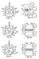
Fig. 7a is a plan view of a portion of the intervertebral prosthetic disc shown laterally disposed in an intervertebral space. -
Fig. 7b is a lateral view of the arrangement ofFig. 7a . -
Fig. 8a is a plan view of a portion of the intervertebral prosthetic disc shown laterally disposed in an offset manner in an intervertebral space. -
Fig. 8b is a lateral view of the arrangement ofFig. 8a . -
Fig. 9a is a plan view of a portion of the intervertebral prosthetic disc shown laterally disposed in an offset manner in an intervertebral space. -
Fig. 9b is a lateral view of the arrangement ofFig. 9a . -
Fig. 10 is a plan view of a portion of an alternative intervertebral disc prosthesis as such not disclosing an embodiment according to the present invention (the claimed length to width ratio not being explicity mentionned), but describing certain aspects of the invention. - This disclosure relates generally to intervertebral disc prostheses for lateral insertion and, in some instances, laterally offset insertion. For the purposes of promoting an understanding of the principles of the disclosure, reference will now be made to the embodiments, or examples, illustrated in the drawings and specific language will be used to describe the same. It will nevertheless be understood that no limitation of the scope of the disclosure is thereby intended. Any alterations and further modifications in the described embodiments, and any further applications of the principles of the disclosure as described herein are contemplated as would normally occur to one skilled in the art to which this disclosure relates. As such, individual features of separately described embodiments can be combined to form additional embodiments.
- Referring now to
Fig. 1 , shown therein is a lateral view of a portion of aspinal column 10, illustrating a group of adjacent upper and lower vertebrae V1, V2, V3, V4 separated by natural intervertebral discs D1, D2, D3. The illustration of four vertebrae is only intended as an example. Another example would be a sacrum and one vertebrae. - Referring now to
Fig. 2 , for the sake of further example, two of the vertebrae will be discussed, designated as aspinal segment 12 including a lower vertebrae VL and an upper vertebrae VU. In one embodiment, some or all of the natural disc that would have been positioned between the two vertebrae VL, VU is typically removed via a discectomy or a similar surgical procedure, the details of which would be known to one of ordinary skill in the art. Removal of the diseased or degenerated disc results in the formation of an intervertebral space S between the upper and lower vertebrae VU, VL. - Referring now to
Figs. 3-5 , shown therein is one embodiment of an intervertebralprosthetic disc 20 for lateral insertion into the intervertebral space S (Fig. 2 ). In one embodiment, theprosthetic disc 20 provides for articulating motion, thereby restoring motion to the spinal segment defined by the upper and lower vertebrae VU, VL. Theprosthetic disc 20 extends generally along a transverse axis T corresponding to the anterior-posterior aspect ofspinal segment 12 and along longitudinal axis L corresponding to the lateral aspect ofspinal segment 12. - The
prosthetic disc 20 includes a firstarticular component 22 and a secondarticular component 24. Thearticular components prosthetic disc 20 which is sized and configured for disposition within the intervertebral space S (Fig. 2 ) between adjacent vertebral bodies VU, VL (Fig. 2 ). Theprosthetic disc 20 provides relative pivotal and rotational movement between the adjacent vertebral bodies to maintain or restore motion substantially similar to the normal bio-mechanical motion provided by a natural intervertebral disc. More specifically, thearticular components articular components articular components prosthetic disc 20 has been illustrated and described as providing a specific combination of articulating motion, it should be understood that other combinations of articulating movement are also possible, such as, for example, relative translational or linear motion, and such movement is contemplated as falling within the scope of the present disclosure. - Although the
articular components prosthetic disc 20 may be formed from a wide variety of materials, in one embodiment of the disclosure, thearticular components articular components - The
articular components bearing surface bearing surfaces articular components -
Articular component 22 includes asupport plate 30 having anarticular surface 32 and theopposite bearing surface 26.Support plate 30 is sized and shaped to provide a technically feasible maximum amount of endplate support for the adjacent vertebra VU (Fig. 2 ) while minimizing the lateral window associated with insertion of theprosthetic disc 20. For example, thesupport plate 30 may be shaped such thatlongitudinal sides support plate 30 are substantially parallel and are separated by a distance D1, which corresponds to the lateral window for insertion as will be further described. Additionally, the lateral sides 38, 40 of thesupport plate 30 may take a curved configuration to correspond to the curvature of the endplate of the adjacent vertebra VU (Fig. 2 ). As can be appreciated, thelongitudinal sides prosthetic disc 20 into the disc space S (Fig. 2 ). In some embodiments, the ratio of the length of thelongitudinal sides - The
support plate 30 may include one ormore notches 42 or other types of indicia for receiving or engaging with a corresponding portion of a surgical instrument (not shown) to aid in the manipulation and insertion of theprosthetic disc 20 within the intervertebral space S (Fig. 2 ) between the adjacent vertebral bodies VU, VL (Fig. 2 ). - Referring to
Fig. 4 , in one embodiment of the disclosure, thearticular component 22 includes arecess 50. In one embodiment, therecess 50 has a concave shape, and is configured as a spherical-shaped socket. However, it should be understood that other configurations of therecess 50 are also contemplated, such as, for example, cylindrical, elliptical or other arcuate configurations or possibly non-arcuate configurations. The remaining portion of thearticular surface 32 can be angled or otherwise configured to facilitate the insertion and/or use of the prosthesis. - Although the
concave recess 50 is illustrated as having a generally smooth, uninterrupted articular surface, it should be understood that a surface depression or cavity may be defined along a portion of therecess 50 to provide a means for clearing out matter, such as particulate debris, that is disposed between the abuttingarticular components - A flange member or
keel 52 extends from the bearingsurface 26 and is configured for disposition within a preformed opening in the adjacent vertebral endplate. As with the bearingsurface 26, thekeel 52 may be coated with a bone-growth promoting substance, such as, for example, a hydroxyapatite coating formed of calcium phosphate. Additionally, thekeel 52 may be roughened prior to being coated with the bone-growth promoting substance to further enhance bone on-growth. In one embodiment, thekeel 52 extends along the axis L and is substantially centered along the bearingsurface 26. However, it should be understood that other positions and orientations of thekeel 52 are also contemplated. - In one embodiment, the
keel 52 longitudinally extends along a substantial portion of thearticular component 22. Such an embodiment would accommodate insertion of the prosthetic joint 20 using a lateral approach as opposed to, for example, an anterior approach. In a further embodiment, thekeel 52 may be angled, tapered, or configured in some other shape to facilitate the functional demands of the keel. In still another embodiment, thekeel 52 may be configured as a winged keel, including a lateral portion (not shown) extending across the main body portion ofkeel 52. - In one embodiment, the
keel 52 includes threeopenings 54 extending therethrough to facilitate bone through-growth to enhance fixation to the adjacent vertebral bodies VU, VL (Fig. 2 ). However, it should be understood that any number ofopenings 54 may be defined through thekeel 52, including a single opening or two or more openings. It should also be understood that theopenings 54 need not necessarily extend entirely through thekeel 52, but may alternatively extend partially therethrough. It should further be understood that thekeel 52 need not necessarily define anyopenings 54 extending either partially or entirely therethrough. Additionally, although theopenings 54 are illustrated as having a circular configuration, it should be understood that other sizes and configurations ofopenings 54 are also contemplated. -
Articular component 24 includes asupport plate 60 having anarticular surface 62 and theopposite bearing surface 28.Support plate 60 is sized and shaped to provide a technically feasible maximum amount of endplate support for the adjacent vertebra VL (Fig. 2 ) while minimizing the lateral window associated with insertion of theprosthetic disc 20. For example, thesupport plate 60 may be shaped such thatlongitudinal sides support plate 30 are substantially parallel and are separated by the distance D2, which corresponds to the lateral window for insertion as will be further described. Additionally, the lateral sides 68, 70 of thesupport plate 60 may take a curved configuration to correspond to the curvature of the endplate of the adjacent vertebra VL (Fig. 2 ). As can be appreciated, thelongitudinal sides prosthetic disc 20 into the disc space S (Fig. 2 ). In some embodiments, the ratio of the length of thelongitudinal sides - In some embodiments,
support plates plates
Thesupport plate 60 may include one ormore notches 72 or other types of indicia for receiving or engaging with a corresponding portion of a surgical instrument (not shown) to aid in the manipulation and insertion of the prosthetic joint 20 within the intervertebral space S (Fig. 2 ) between the adjacent vertebral bodies VU, VL (Fig. 2 ). In one embodiment, thenotches 72 are shaped in a manner similar to that of thenotches 42. - The
notches articular components prosthetic disc 20, and to release thearticular components - In one embodiment of the disclosure, the
articular component 22 includes aprojection 74 having a convex shape, which may be configured as a spherical-shaped ball (half of which is shown). It should be understood that other configurations of theprojection 74 are also contemplated, such as, for example, cylindrical, elliptical or other arcuate configurations or possibly non-arcuate configurations. It should also be understood that the remaining portion ofarticular component 22 may take on planar or non-planar configurations, such as, for example, an angular or conical configuration extending about theprojection 74. - A surface depression or
cavity 75 may be defined along a portion of theprojection 74 to provide a means for clearing out matter, such as particulate debris, that is disposed between the abuttingarticular components projection 74 may alternatively define a generally smooth, uninterrupted articular surface. In another embodiment, each of theconvex projection 74 and theconcave recess 50 may define a surface depression to facilitate removal of particulate matter disposed between the abuttingarticular components - A flange member or
keel 76 extends from the bearingsurface 28 and is configured for disposition within a preformed opening in the adjacent vertebral endplate. As with the bearingsurface 28, thekeel 76 may be coated with a bone-growth promoting substance, such as, for example, a hydroxyapatite coating formed of calcium phosphate. Additionally, thekeel 76 may be roughened prior to being coated with the bone-growth promoting substance to further enhance bone on-growth. In one embodiment, thekeel 76 extends along the axis L and is substantially centered along the bearingsurface 62. However, it should be understood that other positions and orientations of thekeel 76 are also contemplated. - In one embodiment, the
keel 76 longitudinally extends along a substantial portion of thearticular component 24. Such an embodiment would accommodate insertion of theprosthetic disc 20 using a lateral approach as opposed to, for example, an anterior approach. In a further embodiment, thekeel 76 may be angled, tapered, or configured in some other shape to facilitate the functional demands of the keel. In still another embodiment, thekeel 76 may be configured as a winged keel, including a lateral portion (not shown) extending across the main body portion ofkeel 76. - In one embodiment, the
keel 76 includes threeopenings 78 extending therethrough to facilitate bone through-growth to enhance fixation to the adjacent vertebral bodies VU, VL (Fig. 2 ). However, it should be understood that any number ofopenings 78 may be defined through thekeel 76, including a single opening or two or more openings. It should also be understood that theopenings 78 need not necessarily extend entirely through thekeel 76, but may alternatively extend partially therethrough. It should further be understood that thekeel 76 need not necessarily define anyopenings 78 extending either partially or entirely therethrough. Additionally, although theopenings 78 are illustrated as having a circular configuration, it should be understood that other sizes and configurations ofopenings 78 are also contemplated. - Referring now to
Fig. 6 ,articular component 24 is shown exploded from the lower vertebral body VL. In this example, the natural endplate associated with the lower vertebral body VL has been removed. However, it is understood that theprosthetic device 20 may be used in situations where the endplate remains intact with the adjacent vertebral body. The vertebral body VL includes an outer ring ofcortical bone 100, often referred to as the apophyseal ring. The inner portion of the vertebral body VL comprisescancellous bone 102, which is softer and weaker than the cortical bone of the apophyseal ring. The design of thearticular component 24, and therefore theprosthetic device 20, facilitates contact between the prosthetic device and thecortical bone 100 of the apophyseal ring, thereby providing an appropriate bearing surface which prevents subsidence of the prosthetic device into the cancellous bone portion of the lower vertebral body VL. - Referring also to
Figs. 7-9 , theprosthetic disc 20, as represented by thearticular component 24, can be inserted from several differentlateral approaches approach 104a (corresponding withFigs. 7a, 7b ) is a direct lateral insertion trajectory, parallel with the axis L (Fig. 3 ). Theapproach 104b (corresponding withFigs. 8a, 8b ) is an oblique insertion trajectory, 10-degree offset from the axis L. Theapproach 104c (corresponding withFigs. 9a, 9b ) is an oblique insertion trajectory, 20-degree offset from the axis L. The curved shape of the lateral sides 38, 40 and 68, 70 can be chosen to support thedifferent approaches articular components cortical bone 100 of the apophyseal ring. - For example, referring to
Fig. 7a , thearticular component 24 is shaped to span the length of the adjacent vertebral body VL such that the lateral edges 68, 70 of thearticular component 24 are nearly or substantially flush with the edges of the vertebral body VL. Accordingly, thearticular component 24 has sufficient length so that it bears against a technically feasible maximum amount of thecortical bone 100 for a given lateral window. As such, subsidence of thearticular component 24 into the vertebral body VL can be prevented. - Turning now to
Fig. 7b , the lateral window associated with insertion of theprosthetic device 20 into the intervertebral space S (Fig. 2 ) is generally shown. As can be appreciated, the size of the lateral window generally corresponds to the amount of trauma imparted to the vertebral region during lateral insertion of prosthetic devices. In some embodiments, the lateral window has a width that is substantially equal to the distances D1, D2 for each of thearticular components 22, 24 (Fig. 3 ). Accordingly, by minimizing the width of theprosthetic device 20, the lateral window associated with its insertion is in turn reduced. - Referring now to
Figs. 8a and 8b , theprosthetic device 20 can be inserted from anoblique approach 104b rather than adirect lateral approach 104a as shown inFigs. 6 ,7a and 7b . In such embodiments, the width of theprosthetic device 20 defined by the distances D1, D2 between thelongitudinal sides prosthetic device 20 essentially spans the length of the vertebral bodies VU, VL to bear against an optimal amount of cortical bone of the apophyseal ring. -
Figs. 9a and 9b are depicted by way of further example to illustrate that theprosthetic device 20 of the present disclosure can be inserted from the more pronouncedoblique angle 104c (Fig. 6 ) relative to the example ofFigs. 8a and 8b . - Referring to
Fig. 10 , a portion of an alternative prosthetic device is generally referred to byreference numeral 120. Theprosthetic disc 120 includes a firstarticular component 122 and a secondarticular component 124. Thearticular components prosthetic disc 120 which is sized and configured for disposition within the intervertebral space S (Fig. 2 ) between adjacent vertebral bodies VU, VL (Fig. 2 ). Theprosthetic disc 120 provides relative pivotal and rotational movement between the adjacent vertebral bodies to maintain or restore motion substantially similar to the normal bio-mechanical motion provided by a natural intervertebral disc. More specifically, thearticular components articular components articular components prosthetic disc 120 has been illustrated and described as providing a specific combination of articulating motion, it should be understood that other combinations of articulating movement are also possible, such as, for example, relative translational or linear motion, and such movement is contemplated as falling within the scope of the present disclosure. -
Articular component 122 includes asupport plate 130 shaped such thatlongitudinal sides support plate 130 are substantially parallel and are separated by the distance D1. Additionally, the lateral sides of thesupport plate 130 includecurved portions Fig. 2 ) andstraight portions straight portions side 134. As can be appreciated, thelongitudinal sides prosthetic disc 120 into the disc space S (Fig. 2 ). -
Articular component 124 includes asupport plate 160 such thatlongitudinal sides support plate 130 are substantially parallel and are separated by the distance D2. Additionally, the lateral sides of thesupport plate 160 includecurved portions Fig. 2 ) andstraight portions straight portions side 164. As can be appreciated, thelongitudinal sides prosthetic disc 120 into the disc space S (Fig. 2 ). - Accordingly, it is understood that several modifications, changes and substitutions are intended in the foregoing disclosure and, in some instances, some features of the disclosure will be employed without a corresponding use of other features. For example, features such as the
keels U.S. Publication Number 2002/0035400 . It is also understood that all spatial references, such as "inner," "outer," "proximal," and "distal" are for illustrative purposes only and can be varied within the scope of the disclosure. Accordingly, it is appropriate that the appended claims be construed broadly and in a manner consistent with the scope of the disclosure.
Claims (18)
- A prosthetic device (20, 120) for lateral insertion into an intervertebral space (S) between a first vertebral body (VL) and a second vertebral body (VU) forming a spinal segment (12), the prosthetic device (20, 120) - when being inserted into the intervertebral space (S) - extending along a transverse axis (T) corresponding to an anterior-posterior direction of the spinal segment (12) and along a longitudinal axis (L) corresponding to a lateral direction of the spinal segment (12), the prosthetic device (20, 120) comprising a first component (22, 122) for engaging the first vertebral body (VU), a second component (24, 124) for engaging the second vertebral body (VL), and an articulation member (50, 74) positioned between the first and second components (22, 24, 122, 124) to permit articulating motion between the first and second components (22, 24, 122, 124), wherein the first and second components (22, 24, 122, 124)
respectively comprise a support plate (30, 60, 130, 160) with relatively straight and parallel longitudinal sides (34, 36, 64, 66, 134, 136, 164, 166) extending parallel to the longitudinal axis (L) of the prosthetic device (20, 120),
each have a length that - when the prosthetic device (20, 120) is inserted into the intervertebral space (S) - extends upon cortical bone of opposing first and second sides of an apophyseal ring (100) of the corresponding vertebral body (VL, VU), the first and second sides being opposed in the lateral direction of the spinal segment (12), and
each have a width that is smaller than the length and such that it does not extend upon opposing third and fourth sides of the apophyseal ring (100) of the corresponding vertebral body (VL, VU), the third and fourth sides being opposed in the anterior-posterior direction of the spinal segment (12), wherein a ratio of length to width for each of the first and second components (22, 24, 122, 124) is in the range of 1.3:1 to 1.7:1. - The prosthetic device (20) of claim 1 wherein the respective support plate (30, 60) has curved lateral sides (38, 40, 68, 70).
- The prosthetic device (120) of claim 1 wherein the respective support plate (130, 160) has at least one lateral side having a curved portion (138, 140) and a straight portion (139, 141).
- The prosthetic device (20, 120) of claim 1 wherein the articulation member (50, 74) includes a convex portion (74) connected to the second component (24, 124) and a concave portion (50) connected to the first component (22, 122).
- The prosthetic device (20, 120) of claim 1 wherein a spherical shaped protrusion (74) extends from the support plate (60, 160) of the second component (24, 124), and wherein a recess is formed in the support plate (30, 130) of the first component (22, 122), such that the spherical shaped protrusion (74) and the recess (50) comprise the articulation member.
- The prosthetic device (20) of claim 1 wherein the first component (22) includes a first longitudinally-extending flange (52) for engaging the first vertebral body (VU) from a lateral approach, and wherein the second component (24) includes a second longitudinally-extending flange (76) for engaging the second vertebral body (VL) from the lateral approach.
- The prosthetic device (20) of claim 6 wherein the first flange (52) is offset relative to the second flange (76) to accommodate insertion into the first and second vertebral bodies (VL, VU) being in a spondylosed relationship.
- The prosthetic device (20) of claim 6 wherein the first flange (52) is aligned with the second flange (76) to accommodate insertion into the first and second vertebral bodies (VL, VU) being in an aligned relationship.
- The prosthetic device (20) of claim 1 wherein the first component (22) further comprises a first bearing surface (26) adapted to engage the apophyseal ring (100) of the first vertebral body (VU).
- The prosthetic device (20) of claim 9 wherein the first component (22) includes a first longitudinally-extending flange (52) for engaging the first vertebral body (VU) from a lateral approach and wherein the first flange (52) extends along a substantial portion of the first bearing surface (26).
- The prosthetic device (20) of claim 1 wherein the second component (24) further comprises a second bearing surface (28) adapted to engage the apophyseal ring (100) of the second vertebral body (VL).
- The prosthetic device (20) of claim 11 wherein the second component (24) includes a second longitudinally-extending flange (76) for engaging the second vertebral body (VL) from a lateral approach and wherein the second flange (76) extends along a substantial portion of the second bearing surface (28).
- The prosthetic device (20) of claim 6 wherein the first and second flanges (52, 76) each comprise at least one hole (54, 78) therethrough.
- The prosthetic device (20, 120) of claim 6 wherein the first and second flanges (52, 76) are each coated with a bone-growth promoting substance.
- The prosthetic device (20) of claim 1 wherein the first component (22) further comprises a first bearing surface (26) adapted to engage the apophyseal ring (100) of the first vertebral body (VU), and wherein the second component (24) further comprises a second bearing surface (28) adapted to engage the apophyseal ring (100) of the second vertebral body (VL), and wherein the first and second bearing surfaces (26, 28) are each coated with a bone-growth promoting substance.
- The prosthetic device (20, 120) of claim 1 wherein the first and second components (22, 24, 122, 124) and articulation member (50, 74) are formed of a cobalt-chrome-molybdenum metallic alloy.
- The prosthetic device (20) of claim 1 wherein the first and second components (22, 24) each comprise at least one notch (42, 72) formed laterally therein for receiving a surgical instrument.
- The prosthetic device (20, 120) of claim 1 wherein the ratio of length to width for each of the first and second components (22, 24, 122, 124) is in the range of about 1.5:1.
Applications Claiming Priority (2)
| Application Number | Priority Date | Filing Date | Title |
|---|---|---|---|
| US10/839,100 US20050251261A1 (en) | 2004-05-05 | 2004-05-05 | Artificial intervertebral disc for lateral insertion |
| PCT/US2005/015581 WO2005107656A1 (en) | 2004-05-05 | 2005-05-04 | Artificial intervertebral disc for lateral insertion |
Publications (2)
| Publication Number | Publication Date |
|---|---|
| EP1753376A1 EP1753376A1 (en) | 2007-02-21 |
| EP1753376B1 true EP1753376B1 (en) | 2013-01-02 |
Family
ID=34968712
Family Applications (1)
| Application Number | Title | Priority Date | Filing Date |
|---|---|---|---|
| EP05745282A Active EP1753376B1 (en) | 2004-05-05 | 2005-05-04 | Artificial intervertebral disc for lateral insertion |
Country Status (3)
| Country | Link |
|---|---|
| US (1) | US20050251261A1 (en) |
| EP (1) | EP1753376B1 (en) |
| WO (1) | WO2005107656A1 (en) |
Families Citing this family (48)
| Publication number | Priority date | Publication date | Assignee | Title |
|---|---|---|---|---|
| ZA200506026B (en) | 2003-01-31 | 2006-11-29 | Spinalmotion Inc | Intervertebral prosthesis placement instrument |
| WO2004066865A2 (en) | 2003-01-31 | 2004-08-12 | Spinalmotion, Inc. | Spinal midline indicator |
| US7575599B2 (en) | 2004-07-30 | 2009-08-18 | Spinalmotion, Inc. | Intervertebral prosthetic disc with metallic core |
| US10052211B2 (en) | 2003-05-27 | 2018-08-21 | Simplify Medical Pty Ltd. | Prosthetic disc for intervertebral insertion |
| EP2161008B1 (en) | 2003-05-27 | 2014-12-24 | Simplify Medical, Inc. | Method for assembling a prosthetic disc for intervertebral insertion |
| US7713304B2 (en) * | 2003-07-31 | 2010-05-11 | Globus Medical, Inc. | Transforaminal prosthetic spinal disc replacement |
| US7753958B2 (en) | 2003-08-05 | 2010-07-13 | Gordon Charles R | Expandable intervertebral implant |
| US7585326B2 (en) | 2004-08-06 | 2009-09-08 | Spinalmotion, Inc. | Methods and apparatus for intervertebral disc prosthesis insertion |
| US7883543B2 (en) * | 2004-10-01 | 2011-02-08 | Spinal Generations, Llc | Vertebral prosthesis and spinal fixation system |
| WO2006042486A1 (en) * | 2004-10-18 | 2006-04-27 | Buettner-Janz Karin | Intervertebral disk endoprosthesis having a motion-adapted edge for the lumbar and cervical spine |
| CH697330B1 (en) * | 2004-12-28 | 2008-08-29 | Synthes Gmbh | Intervertebral prosthesis. |
| US8083797B2 (en) | 2005-02-04 | 2011-12-27 | Spinalmotion, Inc. | Intervertebral prosthetic disc with shock absorption |
| US20070173941A1 (en) * | 2006-01-25 | 2007-07-26 | Sdgi Holdings, Inc. | Intervertebral prosthetic disc and method of installing same |
| US8252058B2 (en) * | 2006-02-16 | 2012-08-28 | Amedica Corporation | Spinal implant with elliptical articulatory interface |
| AU2007238092A1 (en) | 2006-04-12 | 2007-10-25 | Spinalmotion, Inc. | Posterior spinal device and method |
| US8747471B2 (en) * | 2006-04-13 | 2014-06-10 | Warsaw Orthopedic, Inc. | Vertebral implants including asymmetric endplate contours and methods of use |
| EP2081520B1 (en) | 2006-11-07 | 2017-07-12 | Biomedflex, LLC | Medical implants |
| US7905919B2 (en) * | 2006-11-07 | 2011-03-15 | Biomedflex Llc | Prosthetic joint |
| US7914580B2 (en) | 2006-11-07 | 2011-03-29 | Biomedflex Llc | Prosthetic ball-and-socket joint |
| US8070823B2 (en) | 2006-11-07 | 2011-12-06 | Biomedflex Llc | Prosthetic ball-and-socket joint |
| US8308812B2 (en) | 2006-11-07 | 2012-11-13 | Biomedflex, Llc | Prosthetic joint assembly and joint member therefor |
| US8029574B2 (en) | 2006-11-07 | 2011-10-04 | Biomedflex Llc | Prosthetic knee joint |
| US9005307B2 (en) | 2006-11-07 | 2015-04-14 | Biomedflex, Llc | Prosthetic ball-and-socket joint |
| US20110166671A1 (en) | 2006-11-07 | 2011-07-07 | Kellar Franz W | Prosthetic joint |
| US8512413B2 (en) | 2006-11-07 | 2013-08-20 | Biomedflex, Llc | Prosthetic knee joint |
| US20080114453A1 (en) * | 2006-11-13 | 2008-05-15 | Warsaw Orthopedic, Inc. | Intervertebral prosthetic devices and surgical methods |
| US20080133016A1 (en) * | 2006-11-30 | 2008-06-05 | Warsaw Orthopedic, Inc. | Spinal arthroplasty device compatible with neural integrity monitoring |
| US20080140204A1 (en) * | 2006-12-07 | 2008-06-12 | Warsaw Orthopedic, Inc. | Vertebral Implant Systems and Methods of Use |
| US8715352B2 (en) | 2006-12-14 | 2014-05-06 | Depuy Spine, Inc. | Buckling disc replacement |
| US20080161930A1 (en) * | 2007-01-03 | 2008-07-03 | Warsaw Orthopedic, Inc. | Spinal Prosthesis Systems |
| US7959677B2 (en) * | 2007-01-19 | 2011-06-14 | Flexuspine, Inc. | Artificial functional spinal unit system and method for use |
| US10821003B2 (en) | 2007-06-20 | 2020-11-03 | 3Spline Sezc | Spinal osteotomy |
| US20090043391A1 (en) | 2007-08-09 | 2009-02-12 | Spinalmotion, Inc. | Customized Intervertebral Prosthetic Disc with Shock Absorption |
| US8758441B2 (en) | 2007-10-22 | 2014-06-24 | Spinalmotion, Inc. | Vertebral body replacement and method for spanning a space formed upon removal of a vertebral body |
| US8118873B2 (en) * | 2008-01-16 | 2012-02-21 | Warsaw Orthopedic, Inc. | Total joint replacement |
| US8764833B2 (en) | 2008-03-11 | 2014-07-01 | Spinalmotion, Inc. | Artificial intervertebral disc with lower height |
| US9034038B2 (en) | 2008-04-11 | 2015-05-19 | Spinalmotion, Inc. | Motion limiting insert for an artificial intervertebral disc |
| US20090276051A1 (en) | 2008-05-05 | 2009-11-05 | Spinalmotion, Inc. | Polyaryletherketone Artificial Intervertebral Disc |
| US9220603B2 (en) | 2008-07-02 | 2015-12-29 | Simplify Medical, Inc. | Limited motion prosthetic intervertebral disc |
| WO2010009151A2 (en) | 2008-07-17 | 2010-01-21 | Spinalmotion, Inc. | Artificial intervertebral disc placement system |
| WO2010009153A1 (en) | 2008-07-18 | 2010-01-21 | Spinalmotion, Inc. | Posterior prosthetic intervertebral disc |
| US8998991B2 (en) * | 2011-02-23 | 2015-04-07 | Globus Medical, Inc. | Six degree spine stabilization devices and methods |
| US9017410B2 (en) | 2011-10-26 | 2015-04-28 | Globus Medical, Inc. | Artificial discs |
| US9526627B2 (en) | 2011-11-17 | 2016-12-27 | Exactech, Inc. | Expandable interbody device system and method |
| US9492288B2 (en) | 2013-02-20 | 2016-11-15 | Flexuspine, Inc. | Expandable fusion device for positioning between adjacent vertebral bodies |
| US9198770B2 (en) | 2013-07-31 | 2015-12-01 | Globus Medical, Inc. | Artificial disc devices and related methods of use |
| US10398565B2 (en) | 2014-04-24 | 2019-09-03 | Choice Spine, Llc | Limited profile intervertebral implant with incorporated fastening and locking mechanism |
| US9517144B2 (en) | 2014-04-24 | 2016-12-13 | Exactech, Inc. | Limited profile intervertebral implant with incorporated fastening mechanism |
Family Cites Families (97)
| Publication number | Priority date | Publication date | Assignee | Title |
|---|---|---|---|---|
| GB1030145A (en) * | 1964-04-21 | 1966-05-18 | Paul Wittebol | Improvements in or relating to femoral prostheses |
| US3510883A (en) * | 1967-10-30 | 1970-05-12 | Robert F Cathcart | Joint prosthesis |
| US3740769A (en) * | 1971-02-11 | 1973-06-26 | E Haboush | Prosthesis for hip joints |
| US3903549A (en) * | 1974-06-12 | 1975-09-09 | William Minor Deyerle | Acetabular cup prosthesis component for total or subtotal hip prosthesis system |
| US4039777A (en) * | 1976-06-23 | 1977-08-02 | General Electric Company | Heating apparatus for glass or ceramic cooking vessel |
| US4470158A (en) * | 1978-03-10 | 1984-09-11 | Biomedical Engineering Corp. | Joint endoprosthesis |
| US4681589A (en) * | 1984-06-01 | 1987-07-21 | Tronzo Raymond G | Adjustable acetabular cup prosthesis as part of a total cup replacement system |
| US4550450A (en) * | 1984-07-24 | 1985-11-05 | Kinnett James G | Total shoulder prosthesis system |
| EP0176728B1 (en) * | 1984-09-04 | 1989-07-26 | Humboldt-Universität zu Berlin | Intervertebral-disc prosthesis |
| US4622959A (en) * | 1985-03-05 | 1986-11-18 | Marcus Randall E | Multi-use femoral intramedullary nail |
| US4653487A (en) * | 1986-01-29 | 1987-03-31 | Maale Gerhard E | Intramedullary rod assembly for cement injection system |
| JPH01136655A (en) * | 1987-11-24 | 1989-05-29 | Asahi Optical Co Ltd | Movable type pyramid spacer |
| US4805607A (en) * | 1987-12-03 | 1989-02-21 | Boehringer Mannheim Corporation | Modular intramedullary nail system |
| US4874389A (en) * | 1987-12-07 | 1989-10-17 | Downey Ernest L | Replacement disc |
| US4875474A (en) * | 1988-01-29 | 1989-10-24 | Biomet, Inc. | Variable wall thickness interlocking intramedullary nail |
| DE3809793A1 (en) * | 1988-03-23 | 1989-10-05 | Link Waldemar Gmbh Co | SURGICAL INSTRUMENT SET |
| US4892545A (en) * | 1988-07-14 | 1990-01-09 | Ohio Medical Instrument Company, Inc. | Vertebral lock |
| US4936363A (en) * | 1988-08-15 | 1990-06-26 | The Goodyear Tire & Rubber Company | Tread for a pneumatic tire with circumferential slot to prevent the spread of river wear |
| US5037438A (en) * | 1989-07-25 | 1991-08-06 | Richards Medical Company | Zirconium oxide coated prosthesis for wear and corrosion resistance |
| US4932975A (en) * | 1989-10-16 | 1990-06-12 | Vanderbilt University | Vertebral prosthesis |
| US5004476A (en) * | 1989-10-31 | 1991-04-02 | Tulane University | Porous coated total hip replacement system |
| US5062850A (en) * | 1990-01-16 | 1991-11-05 | University Of Florida | Axially-fixed vertebral body prosthesis and method of fixation |
| FR2659226B1 (en) * | 1990-03-07 | 1992-05-29 | Jbs Sa | PROSTHESIS FOR INTERVERTEBRAL DISCS AND ITS IMPLEMENTATION INSTRUMENTS. |
| US5108442A (en) * | 1991-05-09 | 1992-04-28 | Boehringer Mannheim Corporation | Prosthetic implant locking assembly |
| US5282868A (en) * | 1991-06-17 | 1994-02-01 | Andre Bahler | Prosthetic arrangement for a complex joint, especially knee joint |
| US5290312A (en) * | 1991-09-03 | 1994-03-01 | Alphatec | Artificial vertebral body |
| GB9125798D0 (en) * | 1991-12-04 | 1992-02-05 | Customflex Limited | Improvements in or relating to spinal vertebrae implants |
| US5258031A (en) * | 1992-01-06 | 1993-11-02 | Danek Medical | Intervertebral disk arthroplasty |
| US5425773A (en) * | 1992-01-06 | 1995-06-20 | Danek Medical, Inc. | Intervertebral disk arthroplasty device |
| US5509934A (en) * | 1992-02-28 | 1996-04-23 | Osteonics Corp. | Prosthetic knee tibial component constructed of synthetic polymeric material |
| DE4208115A1 (en) * | 1992-03-13 | 1993-09-16 | Link Waldemar Gmbh Co | DISC ENDOPROTHESIS |
| DE4208116C2 (en) * | 1992-03-13 | 1995-08-03 | Link Waldemar Gmbh Co | Intervertebral disc prosthesis |
| US6102954A (en) * | 1992-05-18 | 2000-08-15 | Astra Aktiebolag | Joint prosthesis and apparatus for preparing the bone prior to fitting of the prosthesis |
| US5344458A (en) * | 1992-08-06 | 1994-09-06 | Bonutti Peter M | Arthroplasty component |
| US5246458A (en) * | 1992-10-07 | 1993-09-21 | Graham Donald V | Artificial disk |
| JPH06178787A (en) * | 1992-12-14 | 1994-06-28 | Shima Yumiko | Centrum spacer with joint, intervertebral cavity measuring device and centrum spacer pattern |
| US5676701A (en) * | 1993-01-14 | 1997-10-14 | Smith & Nephew, Inc. | Low wear artificial spinal disc |
| DE69428143T2 (en) * | 1993-02-09 | 2002-05-29 | Depuy Acromed Inc | disc |
| DE4328062A1 (en) * | 1993-08-20 | 1995-02-23 | Heinrich Ulrich | Implant to replace vertebral bodies and / or to stabilize and fix the spine |
| DE4328690B4 (en) * | 1993-08-26 | 2006-08-17 | SDGI Holdings, Inc., Wilmington | Intervertebral implant for vertebral body blocking and implantation instrument for positioning the intervertebral implant |
| FR2715293B1 (en) * | 1994-01-26 | 1996-03-22 | Biomat | Vertebral interbody fusion cage. |
| US5658347A (en) * | 1994-04-25 | 1997-08-19 | Sarkisian; James S. | Acetabular cup with keel |
| DE9413471U1 (en) * | 1994-08-20 | 1995-12-21 | Schaefer Micomed Gmbh | Ventral intervertebral implant |
| US5674296A (en) * | 1994-11-14 | 1997-10-07 | Spinal Dynamics Corporation | Human spinal disc prosthesis |
| US5609638A (en) * | 1994-11-29 | 1997-03-11 | Zimmer, Inc. | Reinforced polyethylene for articular surfaces |
| US5591235A (en) * | 1995-03-15 | 1997-01-07 | Kuslich; Stephen D. | Spinal fixation device |
| FR2734148A1 (en) * | 1995-05-15 | 1996-11-22 | Biomat | Spinal intervertebral disc replacement prosthesis |
| US6264655B1 (en) * | 1995-06-07 | 2001-07-24 | Madhavan Pisharodi | Cervical disk and spinal stabilizer |
| ATE217174T1 (en) * | 1995-08-25 | 2002-05-15 | Bristol Myers Squibb Co | PROSTHETIC IMPLANT WITH RIBS |
| US5683394A (en) * | 1995-09-29 | 1997-11-04 | Advanced Spine Fixation Systems, Inc. | Fusion mass constrainer |
| US5709683A (en) * | 1995-12-19 | 1998-01-20 | Spine-Tech, Inc. | Interbody bone implant having conjoining stabilization features for bony fusion |
| US5683465A (en) * | 1996-03-18 | 1997-11-04 | Shinn; Gary Lee | Artificial intervertebral disk prosthesis |
| US5755796A (en) * | 1996-06-06 | 1998-05-26 | Ibo; Ivo | Prosthesis of the cervical intervertebralis disk |
| US6159214A (en) * | 1996-07-31 | 2000-12-12 | Michelson; Gary K. | Milling instrumentation and method for preparing a space between adjacent vertebral bodies |
| US5782832A (en) * | 1996-10-01 | 1998-07-21 | Surgical Dynamics, Inc. | Spinal fusion implant and method of insertion thereof |
| US5895428A (en) * | 1996-11-01 | 1999-04-20 | Berry; Don | Load bearing spinal joint implant |
| US6641614B1 (en) * | 1997-05-01 | 2003-11-04 | Spinal Concepts, Inc. | Multi-variable-height fusion device |
| US6146421A (en) * | 1997-08-04 | 2000-11-14 | Gordon, Maya, Roberts And Thomas, Number 1, Llc | Multiple axis intervertebral prosthesis |
| US6228118B1 (en) * | 1997-08-04 | 2001-05-08 | Gordon, Maya, Roberts And Thomas, Number 1, Llc | Multiple axis intervertebral prosthesis |
| US5824094A (en) * | 1997-10-17 | 1998-10-20 | Acromed Corporation | Spinal disc |
| US5888226A (en) * | 1997-11-12 | 1999-03-30 | Rogozinski; Chaim | Intervertebral prosthetic disc |
| US5899941A (en) * | 1997-12-09 | 1999-05-04 | Chubu Bearing Kabushiki Kaisha | Artificial intervertebral disk |
| US6146420A (en) * | 1997-12-10 | 2000-11-14 | Sdgi Holdings, Inc. | Osteogenic fusion device |
| WO1999049818A1 (en) * | 1998-03-30 | 1999-10-07 | Marchosky J Alexander | Prosthetic system |
| CA2329363C (en) * | 1998-04-23 | 2007-12-11 | Cauthen Research Group, Inc. | Articulating spinal implant |
| US6019792A (en) * | 1998-04-23 | 2000-02-01 | Cauthen Research Group, Inc. | Articulating spinal implant |
| US6241769B1 (en) * | 1998-05-06 | 2001-06-05 | Cortek, Inc. | Implant for spinal fusion |
| WO1999060956A1 (en) * | 1998-05-27 | 1999-12-02 | Nuvasive, Inc. | Interlocking spinal inserts |
| EP1681021A3 (en) * | 1998-06-09 | 2009-04-15 | Warsaw Orthopedic, Inc. | Abrading element for preparing a space between adjacent vertebral bodies |
| GB2338652A (en) * | 1998-06-23 | 1999-12-29 | Biomet Merck Ltd | Vertebral body replacement |
| US6063121A (en) * | 1998-07-29 | 2000-05-16 | Xavier; Ravi | Vertebral body prosthesis |
| US6113637A (en) * | 1998-10-22 | 2000-09-05 | Sofamor Danek Holdings, Inc. | Artificial intervertebral joint permitting translational and rotational motion |
| ATE464847T1 (en) * | 1999-01-25 | 2010-05-15 | Warsaw Orthopedic Inc | INSTRUMENT FOR CREATION OF AN INTERVERBEL SPACE FOR ACCOMMODATION OF AN IMPLANT |
| US6368353B1 (en) * | 1999-02-24 | 2002-04-09 | Michel A. Arcand | Shoulder prosthesis apparatus and methods |
| US6113638A (en) * | 1999-02-26 | 2000-09-05 | Williams; Lytton A. | Method and apparatus for intervertebral implant anchorage |
| US6241770B1 (en) * | 1999-03-05 | 2001-06-05 | Gary K. Michelson | Interbody spinal fusion implant having an anatomically conformed trailing end |
| US6368350B1 (en) * | 1999-03-11 | 2002-04-09 | Sulzer Spine-Tech Inc. | Intervertebral disc prosthesis and method |
| JP2003501142A (en) * | 1999-06-04 | 2003-01-14 | エスディージーアイ・ホールディングス・インコーポレーテッド | Artificial implant for intervertebral disc |
| EP1795155B1 (en) * | 1999-07-02 | 2014-03-19 | Spine Solutions Inc. | Intervertebral implant |
| US6592624B1 (en) * | 1999-11-24 | 2003-07-15 | Depuy Acromed, Inc. | Prosthetic implant element |
| FR2805733B1 (en) * | 2000-03-03 | 2002-06-07 | Scient X | DISC PROSTHESIS FOR CERVICAL VERTEBRUS |
| CA2426932A1 (en) * | 2000-10-25 | 2002-06-20 | Sdgi Holdings, Inc. | Vertically expanding intervertebral body fusion device |
| US6692501B2 (en) * | 2000-12-14 | 2004-02-17 | Gary K. Michelson | Spinal interspace shaper |
| US6562045B2 (en) * | 2001-02-13 | 2003-05-13 | Sdgi Holdings, Inc. | Machining apparatus |
| US7169182B2 (en) * | 2001-07-16 | 2007-01-30 | Spinecore, Inc. | Implanting an artificial intervertebral disc |
| US6673113B2 (en) * | 2001-10-18 | 2004-01-06 | Spinecore, Inc. | Intervertebral spacer device having arch shaped spring elements |
| US6989032B2 (en) * | 2001-07-16 | 2006-01-24 | Spinecore, Inc. | Artificial intervertebral disc |
| US6595998B2 (en) * | 2001-03-08 | 2003-07-22 | Spinewave, Inc. | Tissue distraction device |
| US7160327B2 (en) * | 2001-07-16 | 2007-01-09 | Spinecore, Inc. | Axially compressible artificial intervertebral disc having limited rotation using a captured ball and socket joint with a solid ball and compression locking post |
| US7294131B2 (en) * | 2001-11-16 | 2007-11-13 | Warsaw Orthopedic, Inc. | Bone removal device |
| US6740118B2 (en) * | 2002-01-09 | 2004-05-25 | Sdgi Holdings, Inc. | Intervertebral prosthetic joint |
| RU2303422C2 (en) * | 2002-03-12 | 2007-07-27 | Сервитек Инк. | Intervertebral prosthesis and system of intervertebral prostheses, in peculiar case, for cervical department of vertebral column |
| US7066958B2 (en) * | 2002-05-10 | 2006-06-27 | Ferree Bret A | Prosthetic components with partially contained compressible resilient members |
| CA2502292C (en) * | 2002-10-31 | 2011-07-26 | Spinal Concepts, Inc. | Movable disc implant |
| US7364589B2 (en) * | 2003-02-12 | 2008-04-29 | Warsaw Orthopedic, Inc. | Mobile bearing articulating disc |
| US7250060B2 (en) * | 2004-01-27 | 2007-07-31 | Sdgi Holdings, Inc. | Hybrid intervertebral disc system |
| US7485146B1 (en) * | 2004-03-08 | 2009-02-03 | Nuvasive, Inc. | Total disc replacement system and related methods |
-
2004
- 2004-05-05 US US10/839,100 patent/US20050251261A1/en not_active Abandoned
-
2005
- 2005-05-04 EP EP05745282A patent/EP1753376B1/en active Active
- 2005-05-04 WO PCT/US2005/015581 patent/WO2005107656A1/en active Application Filing
Also Published As
| Publication number | Publication date |
|---|---|
| EP1753376A1 (en) | 2007-02-21 |
| US20050251261A1 (en) | 2005-11-10 |
| WO2005107656A1 (en) | 2005-11-17 |
Similar Documents
| Publication | Publication Date | Title |
|---|---|---|
| EP1753376B1 (en) | Artificial intervertebral disc for lateral insertion | |
| US7682397B2 (en) | Revisable prosthetic device | |
| US7594919B2 (en) | Artificial disc inserter | |
| US7179294B2 (en) | Articular disc prosthesis and method for implanting the same | |
| US6740118B2 (en) | Intervertebral prosthetic joint | |
| US20040230307A1 (en) | Device for fusing two bone segments | |
| US20080114453A1 (en) | Intervertebral prosthetic devices and surgical methods | |
| US20050203626A1 (en) | System and method for stabilizing a prosthetic device | |
| US20070179615A1 (en) | Intervertebral prosthetic disc | |
| US20080051902A1 (en) | Modular intervertebral disc prosthesis and method of replacing an intervertebral disc | |
| US20090326658A1 (en) | Intervertebral prosthetic disc and method of installing same | |
| CA2560803A1 (en) | Constrained artificial implant for orthopaedic applications | |
| US20070173942A1 (en) | Intervertebral prosthetic disc | |
| AU2004211984A1 (en) | Device for fusing two bone segments | |
| KR20040077868A (en) | Intervertebral prosthetic joint |
Legal Events
| Date | Code | Title | Description |
|---|---|---|---|
| PUAI | Public reference made under article 153(3) epc to a published international application that has entered the european phase |
Free format text: ORIGINAL CODE: 0009012 |
|
| 17P | Request for examination filed |
Effective date: 20061128 |
|
| AK | Designated contracting states |
Kind code of ref document: A1 Designated state(s): AT BE BG CH CY CZ DE DK EE ES FI FR GB GR HU IE IS IT LI LT LU MC NL PL PT RO SE SI SK TR |
|
| RIN1 | Information on inventor provided before grant (corrected) |
Inventor name: PETERMAN, MARC, M. |
|
| DAX | Request for extension of the european patent (deleted) | ||
| 17Q | First examination report despatched |
Effective date: 20090713 |
|
| GRAC | Information related to communication of intention to grant a patent modified |
Free format text: ORIGINAL CODE: EPIDOSCIGR1 |
|
| GRAP | Despatch of communication of intention to grant a patent |
Free format text: ORIGINAL CODE: EPIDOSNIGR1 |
|
| GRAS | Grant fee paid |
Free format text: ORIGINAL CODE: EPIDOSNIGR3 |
|
| GRAP | Despatch of communication of intention to grant a patent |
Free format text: ORIGINAL CODE: EPIDOSNIGR1 |
|
| GRAA | (expected) grant |
Free format text: ORIGINAL CODE: 0009210 |
|
| AK | Designated contracting states |
Kind code of ref document: B1 Designated state(s): AT BE BG CH CY CZ DE DK EE ES FI FR GB GR HU IE IS IT LI LT LU MC NL PL PT RO SE SI SK TR |
|
| REG | Reference to a national code |
Ref country code: GB Ref legal event code: FG4D |
|
| REG | Reference to a national code |
Ref country code: CH Ref legal event code: EP Ref country code: AT Ref legal event code: REF Ref document number: 591138 Country of ref document: AT Kind code of ref document: T Effective date: 20130115 |
|
| REG | Reference to a national code |
Ref country code: IE Ref legal event code: FG4D |
|
| REG | Reference to a national code |
Ref country code: DE Ref legal event code: R096 Ref document number: 602005037716 Country of ref document: DE Effective date: 20130228 |
|
| REG | Reference to a national code |
Ref country code: AT Ref legal event code: MK05 Ref document number: 591138 Country of ref document: AT Kind code of ref document: T Effective date: 20130102 |
|
| REG | Reference to a national code |
Ref country code: NL Ref legal event code: VDEP Effective date: 20130102 |
|
| PG25 | Lapsed in a contracting state [announced via postgrant information from national office to epo] |
Ref country code: SI Free format text: LAPSE BECAUSE OF FAILURE TO SUBMIT A TRANSLATION OF THE DESCRIPTION OR TO PAY THE FEE WITHIN THE PRESCRIBED TIME-LIMIT Effective date: 20130102 |
|
| REG | Reference to a national code |
Ref country code: LT Ref legal event code: MG4D |
|
| PG25 | Lapsed in a contracting state [announced via postgrant information from national office to epo] |
Ref country code: BG Free format text: LAPSE BECAUSE OF FAILURE TO SUBMIT A TRANSLATION OF THE DESCRIPTION OR TO PAY THE FEE WITHIN THE PRESCRIBED TIME-LIMIT Effective date: 20130402 Ref country code: AT Free format text: LAPSE BECAUSE OF FAILURE TO SUBMIT A TRANSLATION OF THE DESCRIPTION OR TO PAY THE FEE WITHIN THE PRESCRIBED TIME-LIMIT Effective date: 20130102 Ref country code: CZ Free format text: LAPSE BECAUSE OF FAILURE TO SUBMIT A TRANSLATION OF THE DESCRIPTION OR TO PAY THE FEE WITHIN THE PRESCRIBED TIME-LIMIT Effective date: 20130102 Ref country code: SE Free format text: LAPSE BECAUSE OF FAILURE TO SUBMIT A TRANSLATION OF THE DESCRIPTION OR TO PAY THE FEE WITHIN THE PRESCRIBED TIME-LIMIT Effective date: 20130102 Ref country code: BE Free format text: LAPSE BECAUSE OF FAILURE TO SUBMIT A TRANSLATION OF THE DESCRIPTION OR TO PAY THE FEE WITHIN THE PRESCRIBED TIME-LIMIT Effective date: 20130102 Ref country code: IS Free format text: LAPSE BECAUSE OF FAILURE TO SUBMIT A TRANSLATION OF THE DESCRIPTION OR TO PAY THE FEE WITHIN THE PRESCRIBED TIME-LIMIT Effective date: 20130502 Ref country code: LT Free format text: LAPSE BECAUSE OF FAILURE TO SUBMIT A TRANSLATION OF THE DESCRIPTION OR TO PAY THE FEE WITHIN THE PRESCRIBED TIME-LIMIT Effective date: 20130102 Ref country code: ES Free format text: LAPSE BECAUSE OF FAILURE TO SUBMIT A TRANSLATION OF THE DESCRIPTION OR TO PAY THE FEE WITHIN THE PRESCRIBED TIME-LIMIT Effective date: 20130413 |
|
| PG25 | Lapsed in a contracting state [announced via postgrant information from national office to epo] |
Ref country code: NL Free format text: LAPSE BECAUSE OF FAILURE TO SUBMIT A TRANSLATION OF THE DESCRIPTION OR TO PAY THE FEE WITHIN THE PRESCRIBED TIME-LIMIT Effective date: 20130102 Ref country code: FI Free format text: LAPSE BECAUSE OF FAILURE TO SUBMIT A TRANSLATION OF THE DESCRIPTION OR TO PAY THE FEE WITHIN THE PRESCRIBED TIME-LIMIT Effective date: 20130102 Ref country code: PL Free format text: LAPSE BECAUSE OF FAILURE TO SUBMIT A TRANSLATION OF THE DESCRIPTION OR TO PAY THE FEE WITHIN THE PRESCRIBED TIME-LIMIT Effective date: 20130102 Ref country code: GR Free format text: LAPSE BECAUSE OF FAILURE TO SUBMIT A TRANSLATION OF THE DESCRIPTION OR TO PAY THE FEE WITHIN THE PRESCRIBED TIME-LIMIT Effective date: 20130403 Ref country code: PT Free format text: LAPSE BECAUSE OF FAILURE TO SUBMIT A TRANSLATION OF THE DESCRIPTION OR TO PAY THE FEE WITHIN THE PRESCRIBED TIME-LIMIT Effective date: 20130502 |
|
| PG25 | Lapsed in a contracting state [announced via postgrant information from national office to epo] |
Ref country code: DK Free format text: LAPSE BECAUSE OF FAILURE TO SUBMIT A TRANSLATION OF THE DESCRIPTION OR TO PAY THE FEE WITHIN THE PRESCRIBED TIME-LIMIT Effective date: 20130102 Ref country code: RO Free format text: LAPSE BECAUSE OF FAILURE TO SUBMIT A TRANSLATION OF THE DESCRIPTION OR TO PAY THE FEE WITHIN THE PRESCRIBED TIME-LIMIT Effective date: 20130102 Ref country code: EE Free format text: LAPSE BECAUSE OF FAILURE TO SUBMIT A TRANSLATION OF THE DESCRIPTION OR TO PAY THE FEE WITHIN THE PRESCRIBED TIME-LIMIT Effective date: 20130102 Ref country code: SK Free format text: LAPSE BECAUSE OF FAILURE TO SUBMIT A TRANSLATION OF THE DESCRIPTION OR TO PAY THE FEE WITHIN THE PRESCRIBED TIME-LIMIT Effective date: 20130102 |
|
| PLBE | No opposition filed within time limit |
Free format text: ORIGINAL CODE: 0009261 |
|
| STAA | Information on the status of an ep patent application or granted ep patent |
Free format text: STATUS: NO OPPOSITION FILED WITHIN TIME LIMIT |
|
| PG25 | Lapsed in a contracting state [announced via postgrant information from national office to epo] |
Ref country code: CY Free format text: LAPSE BECAUSE OF FAILURE TO SUBMIT A TRANSLATION OF THE DESCRIPTION OR TO PAY THE FEE WITHIN THE PRESCRIBED TIME-LIMIT Effective date: 20130102 |
|
| 26N | No opposition filed |
Effective date: 20131003 |
|
| PG25 | Lapsed in a contracting state [announced via postgrant information from national office to epo] |
Ref country code: MC Free format text: LAPSE BECAUSE OF FAILURE TO SUBMIT A TRANSLATION OF THE DESCRIPTION OR TO PAY THE FEE WITHIN THE PRESCRIBED TIME-LIMIT Effective date: 20130102 Ref country code: IT Free format text: LAPSE BECAUSE OF FAILURE TO SUBMIT A TRANSLATION OF THE DESCRIPTION OR TO PAY THE FEE WITHIN THE PRESCRIBED TIME-LIMIT Effective date: 20130102 |
|
| REG | Reference to a national code |
Ref country code: CH Ref legal event code: PL |
|
| REG | Reference to a national code |
Ref country code: DE Ref legal event code: R097 Ref document number: 602005037716 Country of ref document: DE Effective date: 20131003 |
|
| GBPC | Gb: european patent ceased through non-payment of renewal fee |
Effective date: 20130504 |
|
| PG25 | Lapsed in a contracting state [announced via postgrant information from national office to epo] |
Ref country code: LI Free format text: LAPSE BECAUSE OF NON-PAYMENT OF DUE FEES Effective date: 20130531 Ref country code: CH Free format text: LAPSE BECAUSE OF NON-PAYMENT OF DUE FEES Effective date: 20130531 |
|
| REG | Reference to a national code |
Ref country code: IE Ref legal event code: MM4A |
|
| PG25 | Lapsed in a contracting state [announced via postgrant information from national office to epo] |
Ref country code: GB Free format text: LAPSE BECAUSE OF NON-PAYMENT OF DUE FEES Effective date: 20130504 Ref country code: IE Free format text: LAPSE BECAUSE OF NON-PAYMENT OF DUE FEES Effective date: 20130504 |
|
| PG25 | Lapsed in a contracting state [announced via postgrant information from national office to epo] |
Ref country code: TR Free format text: LAPSE BECAUSE OF FAILURE TO SUBMIT A TRANSLATION OF THE DESCRIPTION OR TO PAY THE FEE WITHIN THE PRESCRIBED TIME-LIMIT Effective date: 20130102 |
|
| PG25 | Lapsed in a contracting state [announced via postgrant information from national office to epo] |
Ref country code: LU Free format text: LAPSE BECAUSE OF NON-PAYMENT OF DUE FEES Effective date: 20130504 Ref country code: HU Free format text: LAPSE BECAUSE OF FAILURE TO SUBMIT A TRANSLATION OF THE DESCRIPTION OR TO PAY THE FEE WITHIN THE PRESCRIBED TIME-LIMIT; INVALID AB INITIO Effective date: 20050504 |
|
| REG | Reference to a national code |
Ref country code: FR Ref legal event code: PLFP Year of fee payment: 12 |
|
| REG | Reference to a national code |
Ref country code: FR Ref legal event code: PLFP Year of fee payment: 13 |
|
| REG | Reference to a national code |
Ref country code: FR Ref legal event code: PLFP Year of fee payment: 14 |
|
| PGFP | Annual fee paid to national office [announced via postgrant information from national office to epo] |
Ref country code: FR Payment date: 20220421 Year of fee payment: 18 Ref country code: DE Payment date: 20220420 Year of fee payment: 18 |
|
| REG | Reference to a national code |
Ref country code: DE Ref legal event code: R119 Ref document number: 602005037716 Country of ref document: DE |