EP1752116A1 - Intervertebral Implant - Google Patents
Intervertebral Implant Download PDFInfo
- Publication number
- EP1752116A1 EP1752116A1 EP05405472A EP05405472A EP1752116A1 EP 1752116 A1 EP1752116 A1 EP 1752116A1 EP 05405472 A EP05405472 A EP 05405472A EP 05405472 A EP05405472 A EP 05405472A EP 1752116 A1 EP1752116 A1 EP 1752116A1
- Authority
- EP
- European Patent Office
- Prior art keywords
- parts
- implant according
- implant
- disc space
- spring
- Prior art date
- Legal status (The legal status is an assumption and is not a legal conclusion. Google has not performed a legal analysis and makes no representation as to the accuracy of the status listed.)
- Withdrawn
Links
Images


Classifications
-
- A—HUMAN NECESSITIES
- A61—MEDICAL OR VETERINARY SCIENCE; HYGIENE
- A61F—FILTERS IMPLANTABLE INTO BLOOD VESSELS; PROSTHESES; DEVICES PROVIDING PATENCY TO, OR PREVENTING COLLAPSING OF, TUBULAR STRUCTURES OF THE BODY, e.g. STENTS; ORTHOPAEDIC, NURSING OR CONTRACEPTIVE DEVICES; FOMENTATION; TREATMENT OR PROTECTION OF EYES OR EARS; BANDAGES, DRESSINGS OR ABSORBENT PADS; FIRST-AID KITS
- A61F2/00—Filters implantable into blood vessels; Prostheses, i.e. artificial substitutes or replacements for parts of the body; Appliances for connecting them with the body; Devices providing patency to, or preventing collapsing of, tubular structures of the body, e.g. stents
- A61F2/02—Prostheses implantable into the body
- A61F2/30—Joints
- A61F2/44—Joints for the spine, e.g. vertebrae, spinal discs
- A61F2/4455—Joints for the spine, e.g. vertebrae, spinal discs for the fusion of spinal bodies, e.g. intervertebral fusion of adjacent spinal bodies, e.g. fusion cages
- A61F2/4465—Joints for the spine, e.g. vertebrae, spinal discs for the fusion of spinal bodies, e.g. intervertebral fusion of adjacent spinal bodies, e.g. fusion cages having a circular or kidney shaped cross-section substantially perpendicular to the axis of the spine
-
- A—HUMAN NECESSITIES
- A61—MEDICAL OR VETERINARY SCIENCE; HYGIENE
- A61F—FILTERS IMPLANTABLE INTO BLOOD VESSELS; PROSTHESES; DEVICES PROVIDING PATENCY TO, OR PREVENTING COLLAPSING OF, TUBULAR STRUCTURES OF THE BODY, e.g. STENTS; ORTHOPAEDIC, NURSING OR CONTRACEPTIVE DEVICES; FOMENTATION; TREATMENT OR PROTECTION OF EYES OR EARS; BANDAGES, DRESSINGS OR ABSORBENT PADS; FIRST-AID KITS
- A61F2/00—Filters implantable into blood vessels; Prostheses, i.e. artificial substitutes or replacements for parts of the body; Appliances for connecting them with the body; Devices providing patency to, or preventing collapsing of, tubular structures of the body, e.g. stents
- A61F2/02—Prostheses implantable into the body
- A61F2/30—Joints
- A61F2/44—Joints for the spine, e.g. vertebrae, spinal discs
- A61F2/4455—Joints for the spine, e.g. vertebrae, spinal discs for the fusion of spinal bodies, e.g. intervertebral fusion of adjacent spinal bodies, e.g. fusion cages
-
- A—HUMAN NECESSITIES
- A61—MEDICAL OR VETERINARY SCIENCE; HYGIENE
- A61F—FILTERS IMPLANTABLE INTO BLOOD VESSELS; PROSTHESES; DEVICES PROVIDING PATENCY TO, OR PREVENTING COLLAPSING OF, TUBULAR STRUCTURES OF THE BODY, e.g. STENTS; ORTHOPAEDIC, NURSING OR CONTRACEPTIVE DEVICES; FOMENTATION; TREATMENT OR PROTECTION OF EYES OR EARS; BANDAGES, DRESSINGS OR ABSORBENT PADS; FIRST-AID KITS
- A61F2/00—Filters implantable into blood vessels; Prostheses, i.e. artificial substitutes or replacements for parts of the body; Appliances for connecting them with the body; Devices providing patency to, or preventing collapsing of, tubular structures of the body, e.g. stents
- A61F2/02—Prostheses implantable into the body
- A61F2/30—Joints
- A61F2/3094—Designing or manufacturing processes
- A61F2/30965—Reinforcing the prosthesis by embedding particles or fibres during moulding or dipping
-
- A—HUMAN NECESSITIES
- A61—MEDICAL OR VETERINARY SCIENCE; HYGIENE
- A61F—FILTERS IMPLANTABLE INTO BLOOD VESSELS; PROSTHESES; DEVICES PROVIDING PATENCY TO, OR PREVENTING COLLAPSING OF, TUBULAR STRUCTURES OF THE BODY, e.g. STENTS; ORTHOPAEDIC, NURSING OR CONTRACEPTIVE DEVICES; FOMENTATION; TREATMENT OR PROTECTION OF EYES OR EARS; BANDAGES, DRESSINGS OR ABSORBENT PADS; FIRST-AID KITS
- A61F2/00—Filters implantable into blood vessels; Prostheses, i.e. artificial substitutes or replacements for parts of the body; Appliances for connecting them with the body; Devices providing patency to, or preventing collapsing of, tubular structures of the body, e.g. stents
- A61F2/02—Prostheses implantable into the body
- A61F2/28—Bones
- A61F2002/2835—Bone graft implants for filling a bony defect or an endoprosthesis cavity, e.g. by synthetic material or biological material
-
- A—HUMAN NECESSITIES
- A61—MEDICAL OR VETERINARY SCIENCE; HYGIENE
- A61F—FILTERS IMPLANTABLE INTO BLOOD VESSELS; PROSTHESES; DEVICES PROVIDING PATENCY TO, OR PREVENTING COLLAPSING OF, TUBULAR STRUCTURES OF THE BODY, e.g. STENTS; ORTHOPAEDIC, NURSING OR CONTRACEPTIVE DEVICES; FOMENTATION; TREATMENT OR PROTECTION OF EYES OR EARS; BANDAGES, DRESSINGS OR ABSORBENT PADS; FIRST-AID KITS
- A61F2/00—Filters implantable into blood vessels; Prostheses, i.e. artificial substitutes or replacements for parts of the body; Appliances for connecting them with the body; Devices providing patency to, or preventing collapsing of, tubular structures of the body, e.g. stents
- A61F2/02—Prostheses implantable into the body
- A61F2/30—Joints
- A61F2002/30001—Additional features of subject-matter classified in A61F2/28, A61F2/30 and subgroups thereof
- A61F2002/30108—Shapes
- A61F2002/30199—Three-dimensional shapes
- A61F2002/302—Three-dimensional shapes toroidal, e.g. rings
-
- A—HUMAN NECESSITIES
- A61—MEDICAL OR VETERINARY SCIENCE; HYGIENE
- A61F—FILTERS IMPLANTABLE INTO BLOOD VESSELS; PROSTHESES; DEVICES PROVIDING PATENCY TO, OR PREVENTING COLLAPSING OF, TUBULAR STRUCTURES OF THE BODY, e.g. STENTS; ORTHOPAEDIC, NURSING OR CONTRACEPTIVE DEVICES; FOMENTATION; TREATMENT OR PROTECTION OF EYES OR EARS; BANDAGES, DRESSINGS OR ABSORBENT PADS; FIRST-AID KITS
- A61F2/00—Filters implantable into blood vessels; Prostheses, i.e. artificial substitutes or replacements for parts of the body; Appliances for connecting them with the body; Devices providing patency to, or preventing collapsing of, tubular structures of the body, e.g. stents
- A61F2/02—Prostheses implantable into the body
- A61F2/30—Joints
- A61F2002/30001—Additional features of subject-matter classified in A61F2/28, A61F2/30 and subgroups thereof
- A61F2002/30108—Shapes
- A61F2002/30199—Three-dimensional shapes
- A61F2002/30224—Three-dimensional shapes cylindrical
- A61F2002/3023—Three-dimensional shapes cylindrical wedge-shaped cylinders
-
- A—HUMAN NECESSITIES
- A61—MEDICAL OR VETERINARY SCIENCE; HYGIENE
- A61F—FILTERS IMPLANTABLE INTO BLOOD VESSELS; PROSTHESES; DEVICES PROVIDING PATENCY TO, OR PREVENTING COLLAPSING OF, TUBULAR STRUCTURES OF THE BODY, e.g. STENTS; ORTHOPAEDIC, NURSING OR CONTRACEPTIVE DEVICES; FOMENTATION; TREATMENT OR PROTECTION OF EYES OR EARS; BANDAGES, DRESSINGS OR ABSORBENT PADS; FIRST-AID KITS
- A61F2/00—Filters implantable into blood vessels; Prostheses, i.e. artificial substitutes or replacements for parts of the body; Appliances for connecting them with the body; Devices providing patency to, or preventing collapsing of, tubular structures of the body, e.g. stents
- A61F2/02—Prostheses implantable into the body
- A61F2/30—Joints
- A61F2002/30001—Additional features of subject-matter classified in A61F2/28, A61F2/30 and subgroups thereof
- A61F2002/30316—The prosthesis having different structural features at different locations within the same prosthesis; Connections between prosthetic parts; Special structural features of bone or joint prostheses not otherwise provided for
- A61F2002/30329—Connections or couplings between prosthetic parts, e.g. between modular parts; Connecting elements
- A61F2002/30383—Connections or couplings between prosthetic parts, e.g. between modular parts; Connecting elements made by laterally inserting a protrusion, e.g. a rib into a complementarily-shaped groove
- A61F2002/30387—Dovetail connection
-
- A—HUMAN NECESSITIES
- A61—MEDICAL OR VETERINARY SCIENCE; HYGIENE
- A61F—FILTERS IMPLANTABLE INTO BLOOD VESSELS; PROSTHESES; DEVICES PROVIDING PATENCY TO, OR PREVENTING COLLAPSING OF, TUBULAR STRUCTURES OF THE BODY, e.g. STENTS; ORTHOPAEDIC, NURSING OR CONTRACEPTIVE DEVICES; FOMENTATION; TREATMENT OR PROTECTION OF EYES OR EARS; BANDAGES, DRESSINGS OR ABSORBENT PADS; FIRST-AID KITS
- A61F2/00—Filters implantable into blood vessels; Prostheses, i.e. artificial substitutes or replacements for parts of the body; Appliances for connecting them with the body; Devices providing patency to, or preventing collapsing of, tubular structures of the body, e.g. stents
- A61F2/02—Prostheses implantable into the body
- A61F2/30—Joints
- A61F2002/30001—Additional features of subject-matter classified in A61F2/28, A61F2/30 and subgroups thereof
- A61F2002/30316—The prosthesis having different structural features at different locations within the same prosthesis; Connections between prosthetic parts; Special structural features of bone or joint prostheses not otherwise provided for
- A61F2002/30329—Connections or couplings between prosthetic parts, e.g. between modular parts; Connecting elements
- A61F2002/30476—Connections or couplings between prosthetic parts, e.g. between modular parts; Connecting elements locked by an additional locking mechanism
- A61F2002/305—Snap connection
-
- A—HUMAN NECESSITIES
- A61—MEDICAL OR VETERINARY SCIENCE; HYGIENE
- A61F—FILTERS IMPLANTABLE INTO BLOOD VESSELS; PROSTHESES; DEVICES PROVIDING PATENCY TO, OR PREVENTING COLLAPSING OF, TUBULAR STRUCTURES OF THE BODY, e.g. STENTS; ORTHOPAEDIC, NURSING OR CONTRACEPTIVE DEVICES; FOMENTATION; TREATMENT OR PROTECTION OF EYES OR EARS; BANDAGES, DRESSINGS OR ABSORBENT PADS; FIRST-AID KITS
- A61F2/00—Filters implantable into blood vessels; Prostheses, i.e. artificial substitutes or replacements for parts of the body; Appliances for connecting them with the body; Devices providing patency to, or preventing collapsing of, tubular structures of the body, e.g. stents
- A61F2/02—Prostheses implantable into the body
- A61F2/30—Joints
- A61F2002/30001—Additional features of subject-matter classified in A61F2/28, A61F2/30 and subgroups thereof
- A61F2002/30316—The prosthesis having different structural features at different locations within the same prosthesis; Connections between prosthetic parts; Special structural features of bone or joint prostheses not otherwise provided for
- A61F2002/30535—Special structural features of bone or joint prostheses not otherwise provided for
- A61F2002/30593—Special structural features of bone or joint prostheses not otherwise provided for hollow
-
- A—HUMAN NECESSITIES
- A61—MEDICAL OR VETERINARY SCIENCE; HYGIENE
- A61F—FILTERS IMPLANTABLE INTO BLOOD VESSELS; PROSTHESES; DEVICES PROVIDING PATENCY TO, OR PREVENTING COLLAPSING OF, TUBULAR STRUCTURES OF THE BODY, e.g. STENTS; ORTHOPAEDIC, NURSING OR CONTRACEPTIVE DEVICES; FOMENTATION; TREATMENT OR PROTECTION OF EYES OR EARS; BANDAGES, DRESSINGS OR ABSORBENT PADS; FIRST-AID KITS
- A61F2/00—Filters implantable into blood vessels; Prostheses, i.e. artificial substitutes or replacements for parts of the body; Appliances for connecting them with the body; Devices providing patency to, or preventing collapsing of, tubular structures of the body, e.g. stents
- A61F2/02—Prostheses implantable into the body
- A61F2/30—Joints
- A61F2002/30001—Additional features of subject-matter classified in A61F2/28, A61F2/30 and subgroups thereof
- A61F2002/30316—The prosthesis having different structural features at different locations within the same prosthesis; Connections between prosthetic parts; Special structural features of bone or joint prostheses not otherwise provided for
- A61F2002/30535—Special structural features of bone or joint prostheses not otherwise provided for
- A61F2002/30599—Special structural features of bone or joint prostheses not otherwise provided for stackable
-
- A—HUMAN NECESSITIES
- A61—MEDICAL OR VETERINARY SCIENCE; HYGIENE
- A61F—FILTERS IMPLANTABLE INTO BLOOD VESSELS; PROSTHESES; DEVICES PROVIDING PATENCY TO, OR PREVENTING COLLAPSING OF, TUBULAR STRUCTURES OF THE BODY, e.g. STENTS; ORTHOPAEDIC, NURSING OR CONTRACEPTIVE DEVICES; FOMENTATION; TREATMENT OR PROTECTION OF EYES OR EARS; BANDAGES, DRESSINGS OR ABSORBENT PADS; FIRST-AID KITS
- A61F2/00—Filters implantable into blood vessels; Prostheses, i.e. artificial substitutes or replacements for parts of the body; Appliances for connecting them with the body; Devices providing patency to, or preventing collapsing of, tubular structures of the body, e.g. stents
- A61F2/02—Prostheses implantable into the body
- A61F2/30—Joints
- A61F2002/30001—Additional features of subject-matter classified in A61F2/28, A61F2/30 and subgroups thereof
- A61F2002/30316—The prosthesis having different structural features at different locations within the same prosthesis; Connections between prosthetic parts; Special structural features of bone or joint prostheses not otherwise provided for
- A61F2002/30535—Special structural features of bone or joint prostheses not otherwise provided for
- A61F2002/30604—Special structural features of bone or joint prostheses not otherwise provided for modular
-
- A—HUMAN NECESSITIES
- A61—MEDICAL OR VETERINARY SCIENCE; HYGIENE
- A61F—FILTERS IMPLANTABLE INTO BLOOD VESSELS; PROSTHESES; DEVICES PROVIDING PATENCY TO, OR PREVENTING COLLAPSING OF, TUBULAR STRUCTURES OF THE BODY, e.g. STENTS; ORTHOPAEDIC, NURSING OR CONTRACEPTIVE DEVICES; FOMENTATION; TREATMENT OR PROTECTION OF EYES OR EARS; BANDAGES, DRESSINGS OR ABSORBENT PADS; FIRST-AID KITS
- A61F2/00—Filters implantable into blood vessels; Prostheses, i.e. artificial substitutes or replacements for parts of the body; Appliances for connecting them with the body; Devices providing patency to, or preventing collapsing of, tubular structures of the body, e.g. stents
- A61F2/02—Prostheses implantable into the body
- A61F2/30—Joints
- A61F2/30767—Special external or bone-contacting surface, e.g. coating for improving bone ingrowth
- A61F2/30771—Special external or bone-contacting surface, e.g. coating for improving bone ingrowth applied in original prostheses, e.g. holes or grooves
- A61F2002/3082—Grooves
-
- A—HUMAN NECESSITIES
- A61—MEDICAL OR VETERINARY SCIENCE; HYGIENE
- A61F—FILTERS IMPLANTABLE INTO BLOOD VESSELS; PROSTHESES; DEVICES PROVIDING PATENCY TO, OR PREVENTING COLLAPSING OF, TUBULAR STRUCTURES OF THE BODY, e.g. STENTS; ORTHOPAEDIC, NURSING OR CONTRACEPTIVE DEVICES; FOMENTATION; TREATMENT OR PROTECTION OF EYES OR EARS; BANDAGES, DRESSINGS OR ABSORBENT PADS; FIRST-AID KITS
- A61F2/00—Filters implantable into blood vessels; Prostheses, i.e. artificial substitutes or replacements for parts of the body; Appliances for connecting them with the body; Devices providing patency to, or preventing collapsing of, tubular structures of the body, e.g. stents
- A61F2/02—Prostheses implantable into the body
- A61F2/30—Joints
- A61F2/30767—Special external or bone-contacting surface, e.g. coating for improving bone ingrowth
- A61F2/30771—Special external or bone-contacting surface, e.g. coating for improving bone ingrowth applied in original prostheses, e.g. holes or grooves
- A61F2002/30878—Special external or bone-contacting surface, e.g. coating for improving bone ingrowth applied in original prostheses, e.g. holes or grooves with non-sharp protrusions, for instance contacting the bone for anchoring, e.g. keels, pegs, pins, posts, shanks, stems, struts
- A61F2002/30879—Ribs
-
- A—HUMAN NECESSITIES
- A61—MEDICAL OR VETERINARY SCIENCE; HYGIENE
- A61F—FILTERS IMPLANTABLE INTO BLOOD VESSELS; PROSTHESES; DEVICES PROVIDING PATENCY TO, OR PREVENTING COLLAPSING OF, TUBULAR STRUCTURES OF THE BODY, e.g. STENTS; ORTHOPAEDIC, NURSING OR CONTRACEPTIVE DEVICES; FOMENTATION; TREATMENT OR PROTECTION OF EYES OR EARS; BANDAGES, DRESSINGS OR ABSORBENT PADS; FIRST-AID KITS
- A61F2/00—Filters implantable into blood vessels; Prostheses, i.e. artificial substitutes or replacements for parts of the body; Appliances for connecting them with the body; Devices providing patency to, or preventing collapsing of, tubular structures of the body, e.g. stents
- A61F2/02—Prostheses implantable into the body
- A61F2/30—Joints
- A61F2/44—Joints for the spine, e.g. vertebrae, spinal discs
- A61F2002/448—Joints for the spine, e.g. vertebrae, spinal discs comprising multiple adjacent spinal implants within the same intervertebral space or within the same vertebra, e.g. comprising two adjacent spinal implants
-
- A—HUMAN NECESSITIES
- A61—MEDICAL OR VETERINARY SCIENCE; HYGIENE
- A61F—FILTERS IMPLANTABLE INTO BLOOD VESSELS; PROSTHESES; DEVICES PROVIDING PATENCY TO, OR PREVENTING COLLAPSING OF, TUBULAR STRUCTURES OF THE BODY, e.g. STENTS; ORTHOPAEDIC, NURSING OR CONTRACEPTIVE DEVICES; FOMENTATION; TREATMENT OR PROTECTION OF EYES OR EARS; BANDAGES, DRESSINGS OR ABSORBENT PADS; FIRST-AID KITS
- A61F2/00—Filters implantable into blood vessels; Prostheses, i.e. artificial substitutes or replacements for parts of the body; Appliances for connecting them with the body; Devices providing patency to, or preventing collapsing of, tubular structures of the body, e.g. stents
- A61F2/02—Prostheses implantable into the body
- A61F2/30—Joints
- A61F2/46—Special tools or methods for implanting or extracting artificial joints, accessories, bone grafts or substitutes, or particular adaptations therefor
- A61F2/4603—Special tools or methods for implanting or extracting artificial joints, accessories, bone grafts or substitutes, or particular adaptations therefor for insertion or extraction of endoprosthetic joints or of accessories thereof
- A61F2002/4629—Special tools or methods for implanting or extracting artificial joints, accessories, bone grafts or substitutes, or particular adaptations therefor for insertion or extraction of endoprosthetic joints or of accessories thereof connected to the endoprosthesis or implant via a threaded connection
-
- A—HUMAN NECESSITIES
- A61—MEDICAL OR VETERINARY SCIENCE; HYGIENE
- A61F—FILTERS IMPLANTABLE INTO BLOOD VESSELS; PROSTHESES; DEVICES PROVIDING PATENCY TO, OR PREVENTING COLLAPSING OF, TUBULAR STRUCTURES OF THE BODY, e.g. STENTS; ORTHOPAEDIC, NURSING OR CONTRACEPTIVE DEVICES; FOMENTATION; TREATMENT OR PROTECTION OF EYES OR EARS; BANDAGES, DRESSINGS OR ABSORBENT PADS; FIRST-AID KITS
- A61F2220/00—Fixations or connections for prostheses classified in groups A61F2/00 - A61F2/26 or A61F2/82 or A61F9/00 or A61F11/00 or subgroups thereof
- A61F2220/0025—Connections or couplings between prosthetic parts, e.g. between modular parts; Connecting elements
-
- A—HUMAN NECESSITIES
- A61—MEDICAL OR VETERINARY SCIENCE; HYGIENE
- A61F—FILTERS IMPLANTABLE INTO BLOOD VESSELS; PROSTHESES; DEVICES PROVIDING PATENCY TO, OR PREVENTING COLLAPSING OF, TUBULAR STRUCTURES OF THE BODY, e.g. STENTS; ORTHOPAEDIC, NURSING OR CONTRACEPTIVE DEVICES; FOMENTATION; TREATMENT OR PROTECTION OF EYES OR EARS; BANDAGES, DRESSINGS OR ABSORBENT PADS; FIRST-AID KITS
- A61F2230/00—Geometry of prostheses classified in groups A61F2/00 - A61F2/26 or A61F2/82 or A61F9/00 or A61F11/00 or subgroups thereof
- A61F2230/0063—Three-dimensional shapes
- A61F2230/0065—Three-dimensional shapes toroidal, e.g. ring-shaped, doughnut-shaped
-
- A—HUMAN NECESSITIES
- A61—MEDICAL OR VETERINARY SCIENCE; HYGIENE
- A61F—FILTERS IMPLANTABLE INTO BLOOD VESSELS; PROSTHESES; DEVICES PROVIDING PATENCY TO, OR PREVENTING COLLAPSING OF, TUBULAR STRUCTURES OF THE BODY, e.g. STENTS; ORTHOPAEDIC, NURSING OR CONTRACEPTIVE DEVICES; FOMENTATION; TREATMENT OR PROTECTION OF EYES OR EARS; BANDAGES, DRESSINGS OR ABSORBENT PADS; FIRST-AID KITS
- A61F2230/00—Geometry of prostheses classified in groups A61F2/00 - A61F2/26 or A61F2/82 or A61F9/00 or A61F11/00 or subgroups thereof
- A61F2230/0063—Three-dimensional shapes
- A61F2230/0069—Three-dimensional shapes cylindrical
-
- A—HUMAN NECESSITIES
- A61—MEDICAL OR VETERINARY SCIENCE; HYGIENE
- A61F—FILTERS IMPLANTABLE INTO BLOOD VESSELS; PROSTHESES; DEVICES PROVIDING PATENCY TO, OR PREVENTING COLLAPSING OF, TUBULAR STRUCTURES OF THE BODY, e.g. STENTS; ORTHOPAEDIC, NURSING OR CONTRACEPTIVE DEVICES; FOMENTATION; TREATMENT OR PROTECTION OF EYES OR EARS; BANDAGES, DRESSINGS OR ABSORBENT PADS; FIRST-AID KITS
- A61F2250/00—Special features of prostheses classified in groups A61F2/00 - A61F2/26 or A61F2/82 or A61F9/00 or A61F11/00 or subgroups thereof
- A61F2250/0058—Additional features; Implant or prostheses properties not otherwise provided for
- A61F2250/006—Additional features; Implant or prostheses properties not otherwise provided for modular
- A61F2250/0063—Nested prosthetic parts
-
- A—HUMAN NECESSITIES
- A61—MEDICAL OR VETERINARY SCIENCE; HYGIENE
- A61F—FILTERS IMPLANTABLE INTO BLOOD VESSELS; PROSTHESES; DEVICES PROVIDING PATENCY TO, OR PREVENTING COLLAPSING OF, TUBULAR STRUCTURES OF THE BODY, e.g. STENTS; ORTHOPAEDIC, NURSING OR CONTRACEPTIVE DEVICES; FOMENTATION; TREATMENT OR PROTECTION OF EYES OR EARS; BANDAGES, DRESSINGS OR ABSORBENT PADS; FIRST-AID KITS
- A61F2310/00—Prostheses classified in A61F2/28 or A61F2/30 - A61F2/44 being constructed from or coated with a particular material
- A61F2310/00005—The prosthesis being constructed from a particular material
- A61F2310/00011—Metals or alloys
- A61F2310/00023—Titanium or titanium-based alloys, e.g. Ti-Ni alloys
Definitions
- the invention relates to an intervertebral implant for the connection of adjacent vertebral bodies, with a first part and a second part, which are insertable through an opening (uniportal) in a disc space and connectable to each other in this and each having a central cavity for receiving cancellous bone or bone substitute material ,
- Intervertebral implants have been known for a long time. Also known are intervertebral implants, which are composed of two segments or parts. With such a comparatively large implant, it is possible to support the vertebrae wider than would be possible with a smaller implant. With such a wider support, the vertebrae are less likely to tip over the implant. In addition, the surface pressure exerted by the implant on the end plates of the vertebral bodies, smaller than a narrower implant. Finally, such an implant is less dependent on the configuration of the vertebral end plates.
- An intervertebral implant of two in situ connectable parts is from the WO 03/071992 known. Both parts are designed as L-shaped cages and can each receive spongiosa or a bone substitute material in a recess.
- the two parts must be inserted with a special instrument through two openings (biportal) from behind (posterior) into the disc space. It must therefore left and right two approaches to the disc space and in the Which means a major destruction of the dorsal vertebral elements and traumatization of the spinal canal.
- an intervertebral implant which also consists of two parts or segments.
- the implant In the side view, the implant is wedge-shaped and approximately elliptical in plan view.
- the two parts are successively uniportal introduced into the disc space and lie behind each other in Sagittalcardi. So that the two parts can not separate from each other, they are screwed together after implantation.
- the two parts can be used uniportally via a rear access and finally lie transversely in the disc space. But they can also be used via a transforaminal access. However, they must then be turned in transverse position.
- the invention has for its object to provide an intervertebral implant of the type mentioned, which is even easier and safer uniportal from behind in the disc space can be used.
- an intervertebral implant according to the invention in that the two parts mentioned have connecting means which engage in one another during insertion of the second part into the disc space and connect the two parts with one another.
- a first part and a second part are provided which can be introduced into the intervertebral disc space uniportally transforaminally or extraforaminally.
- the second part connects in situ to the first part detachably or permanently.
- the two parts may be wedge-shaped so that the disc space can be widened with them, which promotes a stable clamping of the intervertebral implant and thus the stability of the spinal fusion.
- the final distraction preferably takes place through the two parts or the intervertebral implant itself.
- At least one part has a groove in which a spring of the other part is slidably inserted.
- the two parts can be assembled during implantation and thus aligned and stabilized against each other.
- the groove and the spring are arranged on inner to be applied to each other narrow sides of the two parts.
- the groove and the spring form a dovetail guide. This ensures that the two parts can not separate from each other in Sagittalcardi. This results in a particularly stable connection between the two parts.
- the two parts can still be made simple and robust.
- the two parts of the intervertebral implant are annular, in particular oval rings and can also be wedge-shaped in the transverse axis with respect to the lordosis to varying degrees. Both parts can be open or one part open and one closed. Preferably, the two parts are insertable into the disc space such that they are arranged one behind the other in the sagittal direction. When the two parts are inserted, they automatically rotate from the direction of insertion into the end position if, according to a development of the invention, they have guide means and in particular a guide notch, a structured surface and / or sharp edges.
- the two parts can be locked together. This prevents the two parts from sliding past each other.
- the lock is preferably designed so that the locking is done automatically in situ.
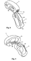
- the implant 1 shown in FIGS. 1, 2 and 3 consists of two parts 2 and 3, which are respectively in the view according to FIG. 3 bean-shaped or annular and which for receiving spondiosa or bone substitute material not shown here opens on two sides have continuous cavity 4 and 5 respectively.
- the two parts 2 and 3 are preferably each made in one piece from a suitable bio-compatible material, for example made of titanium or a reinforced plastic, for example carbon fiber reinforced PEEK.
- the part 2, which is the anterior part in the implanted state according to FIG. 15, has a narrow side 11, which rests at least in regions on a narrow side 10 of the part 3.
- the narrow side 11 is convex and the narrow side 10 is concave.
- Both parts 2 and 3 also have Surfaces 6 and 7 or 6 'and 7'; the surfaces 6 and 6 'as well as the side surfaces 7 and 7' lie substantially in the same area.
- the surfaces 6, 6 ', 7 and 7' each have at one end of the part 2 and the part 3, a distraction surface through which the corresponding end is formed wedge-shaped. These wedge-shaped bevels allow the vertebral bodies to be pushed apart to increase the intervertebral distance.
- 20 guide grooves 19 are arranged in the region of these distraction surfaces, which form recesses and which guide the two parts 2 and 3 respectively during insertion into the disc space. It is on the patent application PCT / EP 2004/002466 of the applicant.
- the part 2 has on the narrow side 11 on a spring 9, which extends substantially over the entire narrow side 11.
- the spring 9 has surfaces 24 which, except in the region of an insertion part 17, extend parallel to one another. In the insertion part 17, these surfaces 24 converge in a wedge shape.
- a shoulder 22 is disposed at the left end of the spring 9, which is wider than the spring 9. The shoulder 22 forms a stop for the part 3, as will be explained in more detail below.
- a locking part 18 is integrally formed on the spring 9, which is as shown plate-shaped or wing-shaped and projects beyond the surfaces 24 on both sides.
- the part 3 has on the surface 10 an insertion opening 25 to which, according to FIG. 6, a continuous slot 26 adjoins, which finally passes according to FIG. 4 into a groove 8.
- a shoulder 22 is formed, which cooperates with the above-mentioned shoulder 23.
- Laterally adjacent to the slot 26 extend webs 27, on each of which a step 21 is formed on the inside, which cooperate with the locking member 18 and form a locking member with this.
- the slot 26 and the opening 25 are formed so that in this the spring 9 is inserted.
- sliding surfaces 28 which are arranged according to Figure 7 next to the spring 9, contact surfaces on the narrow side 10 in the region of the two webs 27.
- the webs 27 are substantially the same width as the sliding surfaces 28.
- the curvature of the sliding surfaces 28 is formed corresponding to the curvature of the narrow side 10, so that there is a flat contact when pushed.
- the surfaces 24 are not necessarily parallel to each other, but may also be inclined so that the spring 9 is trapezoidal in cross-section. Accordingly, the slot 26 is formed. In this case, a dovetail-shaped design results.
- the parts 2 and 3 each have a screw hole 16, to which they are connectable for implantation with an insertion instrument, not shown here.
- introduction instruments are known to the person skilled in the art. It will turn here to the above PCT / EP 2004/002466 pointed.
- the two parts 2 and 3 can be brought together in situ in the disc space B with each other to the implant 1 shown in Figures 1 to 3 and firmly connected to each other.
- the part 2 or the front part and then the part 3 or the rear part is introduced, as shown in Figures 12 to 15.
- Part 3 is guided on the implanted part 2 and inevitably connects to it. The preparation of this connection will be explained in more detail below with reference to FIGS. 6 to 11.
- Figures 6 and 7 show the two parts 2 and 3 before implantation.
- the implantation of the parts 2 and 3 is carried out through an opening BF in the disc space B and thus uniportal and preferably laterally as shown in Figures 12 to 15.
- FIG. 3 shows the part 3 is inserted into the disc space B with an insertion instrument (not shown here). With the same instruments, the part 2 is also introduced into the disc space B through the same opening BF.
- FIG. 9 shows, the part 2 is now guided in such a way that the insertion part 17, which tapers in a wedge shape towards the front, passes through the opening 25 in FIG the slot 26 can be inserted.
- FIG. 10 shows the state in which this insertion part 17 is already in the slot 26.
- the part 2 is guided with the sliding surfaces 28 on Part 3.
- Further guide means are the spring 9 with the insertion part 17, which slide along the webs 27.
- the locking between the two parts 2 and 3 can also be done with other suitable locking means or the like. However, such locking or locking is not mandatory. Also conceivable is an embodiment in which the two parts 2 and 3 are not locked. In such an embodiment, the groove 8 and the slot 46 are preferably formed as a kind of dovetail groove, in which the springs 9 is inserted with a corresponding cross-section. This results in a connection which connects the two parts 2 and 3 in Sagittalraum firmly together.
- Figures 12 to 15 show schematically the insertion and connection of the two parts 2 and 3 through the opening BF to form the implant 1 in the disc space B.
- FIG. 12 shows the part 3, which is introduced with an insertion instrument E1 in the direction of arrow 29 into the cleared disc space B.
- the part 3 is performed in the disc space B as also explained above.
- the guide elements are in particular the guide channel 19 and sharp edges and surface structures according to the PCT / EP2004 / 002466 .
- the part 3 is as shown in Figure 13 between the two vertebrae W, (of which only one of the vertebrae is shown here) in the disc space B in the intended position.
- the part 3 with respect to the disc space B is aligned as shown and is located with its convex narrow side of the disc rings BR of the two adjacent vertebrae W on.
- part 2 is now inserted into the disc space B with an insertion instrument E1.
- the part 3 in this case remains in the position shown in FIG.
- the part 2 is performed as explained above on Part 3 and is further advanced in the direction of arrow 30. During this movement, the above-mentioned locking connection is formed.
- the implant 1 thus formed and shown in FIG. 15 thus forms a unit.
- the two parts 2 and 3 can also be connected in other ways, wherein a locking is not mandatory. Also conceivable is an embodiment in which the engagement takes place only via a groove and a spring.
- the groove may be a dovetail groove or a conventional groove with parallel sidewalls.
Abstract
Description
Die Erfindung betrifft ein Intervertebralimplantat für die Verbindung benachbarter Wirbelkörper, mit einem ersten Teil und einem zweiten Teil, die durch eine Öffnung (uniportal) in einen Bandscheibenraum einführbar und in diesem miteinander verbindbar sind und die jeweils einen zentralen Hohlraum zur Aufnahme von Spongiosa oder Knochenersatzmaterial aufweisen.The invention relates to an intervertebral implant for the connection of adjacent vertebral bodies, with a first part and a second part, which are insertable through an opening (uniportal) in a disc space and connectable to each other in this and each having a central cavity for receiving cancellous bone or bone substitute material ,
Intervertebralimplantate sind seit langem bekannt. Bekannt sind auch Intervertebralimplantate, die aus zwei Segmenten oder Teilen zusammengesetzt sind. Mit einem solchen vergleichsweise grossen Implantat ist es möglich, die Wirbel breiter abzustützen als dies mit einem kleineren Implantat möglich wäre. Bei einer solchen breiteren Abstützung kann der Wirbel weniger leicht über dem Implantat kippen. Zudem ist der Flächendruck, den das Implantat auf die Endplatten der Wirbelkörper ausübt, kleiner als bei einem schmaleren Implantat. Schliesslich ist ein solches Implantat weniger von der Konfiguration der Endplatten der Wirbelkörper abhängig.Intervertebral implants have been known for a long time. Also known are intervertebral implants, which are composed of two segments or parts. With such a comparatively large implant, it is possible to support the vertebrae wider than would be possible with a smaller implant. With such a wider support, the vertebrae are less likely to tip over the implant. In addition, the surface pressure exerted by the implant on the end plates of the vertebral bodies, smaller than a narrower implant. Finally, such an implant is less dependent on the configuration of the vertebral end plates.
Ein Intervertebralimplantat aus zwei in situ miteinander verbindbaren Teilen ist aus der
Durch die
Der Erfindung liegt die Aufgabe zugrunde, ein Intervertebralimplantat der genannten Art zu schaffen, das noch einfacher und sicherer uniportal von hinten in den Bandscheibenraum einsetzbar ist.The invention has for its object to provide an intervertebral implant of the type mentioned, which is even easier and safer uniportal from behind in the disc space can be used.
Die Aufgabe ist bei einem erfindungsgemässen Intervertebralimplantat dadurch gelöst, dass die beiden genannten Teile Verbindungsmittel aufweisen, die beim Einführen des zweiten Teils in den Bandscheibenraum ineinander greifen und die beiden Teile miteinander verbinden. Beim erfindungsgemässen Intervertebralimplantat sind somit ein erster Teil und ein zweiter Teil vorgesehen, die uniportal transforaminal oder extraforaminal in den Bandscheibenraum einführbar sind. Beim Einführen des zweiten Teils in den Bandscheibenraum verbindet sich der zweite Teil in situ mit dem ersten Teil lösbar oder unlösbar. Durch das Zusammenfügen bzw. Verbinden der beiden Teile in situ entsteht insgesamt ein breites Implantat mit den oben genannten Vorteilen. Die Spongiosa bzw. das Knochenersatzmaterial kann bereits in den genannten Teilen vor dem Einsetzen eingefüllt werden. Die beiden Teile können keilförmig ausgebildet sein, so dass mit diesen der Bandscheibenraum erweitert werden kann, was eine stabile Verklemmung des Intervertebralimplantats und damit die Stabilität der Spondylodese fördert. Vor dem Einsetzen der beiden Teile wird der Bandscheibenraum mit an sich bekannten Distraktoren aufgedehnt. Die endgültige Distraktion erfolgt vorzugsweise durch die beiden Teile bzw. das Intervertebralimplantat selbst.The object is achieved with an intervertebral implant according to the invention in that the two parts mentioned have connecting means which engage in one another during insertion of the second part into the disc space and connect the two parts with one another. Thus, in the intervertebral implant according to the invention, a first part and a second part are provided which can be introduced into the intervertebral disc space uniportally transforaminally or extraforaminally. When inserting the second part into the disc space, the second part connects in situ to the first part detachably or permanently. By assembling or joining the two parts in situ, a broad implant with the above-mentioned advantages is produced overall. The cancellous bone or the bone substitute material can already be filled in the mentioned parts before insertion. The two parts may be wedge-shaped so that the disc space can be widened with them, which promotes a stable clamping of the intervertebral implant and thus the stability of the spinal fusion. Before inserting the two parts of the disc space is known per se distractors dilated. The final distraction preferably takes place through the two parts or the intervertebral implant itself.
Nach einer Weiterbildung der Erfindung ist vorgesehen, dass wenigstens ein Teil eine Nut aufweist, in welcher eine Feder des anderen Teils gleitverschieblich einführbar ist. Dadurch können die beiden Teile beim Implantieren zusammengefügt und damit gegeneinander ausgerichtet sowie stabilisiert werden. Vorzugsweise sind die Nut und die Feder an inneren aneinander anzulegenden Schmalseiten der beiden Teile angeordnet. Beim Implantieren des zweiten Teils wird dieser am ersten bereits implantierte Teil geführt und kann damit besser als bisher in die gewünschte Position gebracht werden.According to a development of the invention it is provided that at least one part has a groove in which a spring of the other part is slidably inserted. As a result, the two parts can be assembled during implantation and thus aligned and stabilized against each other. Preferably, the groove and the spring are arranged on inner to be applied to each other narrow sides of the two parts. When implanting the second part of this is performed on the first part already implanted and can thus be brought better than before in the desired position.
Nach einer Weiterbildung der Erfindung ist vorgesehen, dass die Nut und die Feder eine Schwalbenschwanzführung bilden. Dadurch wird erreicht, dass sich die beiden Teile in Sagittalrichtung nicht voneinander lösen können. Dadurch ergibt sich eine besonders stabile Verbindung zwischen den beiden Teilen. Die beiden Teile können trotzdem einfach und robust hergestellt werden.According to a development of the invention it is provided that the groove and the spring form a dovetail guide. This ensures that the two parts can not separate from each other in Sagittalrichtung. This results in a particularly stable connection between the two parts. The two parts can still be made simple and robust.
Vorzugsweise sind die beiden Teile des Intervertebralimplantats ringförmig, insbesondere ovale Ringe und können zudem in der Querachse im Hinblick auf die Lordosierung in unterschiedlichem Ausmass keilförmig ausgebildet sein. Es können beide Teile offen oder auch ein Teil offen und einer geschlossen sein. Vorzugsweise sind die beiden Teile so in den Bandscheibenraum einführbar, dass sie in Sagittalrichtung hintereinander angeordnet sind. Beim Einführen der beiden Teile drehen sich diese von selbst von der Einführungsrichtung in die Endposition, wenn diese gemäss einer Weiterbildung der Erfindung Führungsmittel und insbesondere eine Führungskerbe, eine strukturierte Oberfläche und/oder scharfe Kanten aufweisen.Preferably, the two parts of the intervertebral implant are annular, in particular oval rings and can also be wedge-shaped in the transverse axis with respect to the lordosis to varying degrees. Both parts can be open or one part open and one closed. Preferably, the two parts are insertable into the disc space such that they are arranged one behind the other in the sagittal direction. When the two parts are inserted, they automatically rotate from the direction of insertion into the end position if, according to a development of the invention, they have guide means and in particular a guide notch, a structured surface and / or sharp edges.
Nach einer Weiterbildung der Erfindung ist vorgesehen, dass die beiden Teile miteinander verriegelbar sind. Dadurch wird verhindert, dass die beiden Teile aneinander vorbeigleiten können. Die Verriegelung ist vorzugsweise so ausgebildet, dass die Verriegelung selbsttätig in situ erfolgt.According to a development of the invention, it is provided that the two parts can be locked together. This prevents the two parts from sliding past each other. The lock is preferably designed so that the locking is done automatically in situ.
Weitere vorteilhafte Merkmale ergeben sich aus den abhängigen Patentansprüchen, der nachfolgenden Beschreibung sowie der Zeichnung.Further advantageous features emerge from the dependent claims, the following description and the drawings.
Ausführungsbeispiele der Erfindung werden nachfolgend anhand der Zeichnung näher erläutert. Es zeigen:
Figur 1- eine räumliche schematische Ansicht eines erfindungsgemässen Implantats,
Figur 2- eine weitere räumliche Ansicht des Implantats gemäss
Figur 1, Figur 3- eine Seitenansicht des Implantats,
Figur 4- eine weitere Ansicht des Implantats,
Figur 5- eine räumliche Ansicht des Implantats,
Figur 6- eine räumliche Ansicht des anderen Teils des Implantats,
Figur 7- eine Ansicht des einen Teils des Implantats,
- Fig.8-11
- schematisch einzelne Phasen beim Verbinden der beiden Teile des Implantats und
- Fig. 12-15
- schematisch einzelne Schritte beim Einführen und Verbinden der beiden Teile in den Bandscheibenraum.
- FIG. 1
- a spatial schematic view of an inventive implant,
- FIG. 2
- a further spatial view of the implant according to FIG. 1,
- FIG. 3
- a side view of the implant,
- FIG. 4
- another view of the implant,
- FIG. 5
- a spatial view of the implant,
- FIG. 6
- a spatial view of the other part of the implant,
- FIG. 7
- a view of the part of the implant,
- Fig.8-11
- schematically individual phases in connecting the two parts of the implant and
- Fig. 12-15
- schematically individual steps when inserting and connecting the two parts in the disc space.
Das in den Figuren 1, 2 und 3 gezeigte Implantat 1 besteht aus zwei Teilen 2 und 3, die jeweils in der Ansicht gemäss Figur 3 bohnenförmig bzw. ringförmig ausgebildet sind und die zur Aufnahme von hier nicht gezeigter Spondiosa oder Knochenersatzmaterial einen auf zwei Seiten offenen durchgehenden Hohlraum 4 bzw. 5 aufweisen. Die beiden Teile 2 und 3 sind vorzugsweise jeweils einstückig aus einem geeigneten bio-kompatiblem Material, beispielsweise aus Titan oder einem verstärkten Kunststoff, beispielsweise kohlenfasernverstärktem PEEK hergestellt. Der Teil 2, der im implantierten Zustand gemäss Figur 15 der anteriore Teil ist, besitzt eine Schmalseite 11, die wenigstens bereichsweise an einer Schmalseite 10 des Teils 3 anliegt. Die Schmalseite 11 ist konvex und die Schmalseite 10 konkav ausgebildet. Beide Teile 2 und 3 besitzen zudem Oberflächen 6 und 7 bzw. 6' und 7'; die Oberflächen 6 und 6' als auch die Seitenflächen 7 und 7' liegen im Wesentlichen in der gleichen Fläche. Die Flächen 6, 6', 7 und 7' besitzen jeweils an einem Ende des Teils 2 bzw. des Teils 3 eine Distraktionsfläche, durch welche das entsprechende Ende keilförmig gebildet ist. Diese keilförmigen Abschrägungen ermöglichen ein Auseinanderdrücken der Wirbelkörper zur Vergrösserung der intervertebralen Distanz. Zudem sind im Bereich dieser Distraktionsflächen 20 Führungsrinnen 19 angeordnet, die Vertiefungen bilden und welche die beiden Teile 2 und 3 jeweils beim Einführen in den Bandscheibenraum führen. Es wird hierzu auf die Patentanmeldung
Der Teil 2 weist an der Schmalseite 11 eine Feder 9 auf, die sich im Wesentlichen über die gesamte Schmalseite 11 erstreckt. Die Feder 9 besitzt Oberflächen 24, die mit Ausnahme im Bereich eines Einführungsteiles 17 parallel zueinander verlaufen. Im Einführungsteil 17 laufen diese Oberflächen 24 keilförmig zusammen. In der in Figur 7 gezeigten Stellung ist am linken Ende der Feder 9 eine Schulter 22 angeordnet, die breiter ist als die Feder 9. Die Schulter 22 bildet einen Anschlag für den Teil 3, wie weiter unten näher erläutert wird. Zwischen der Schulter 22 und dem Einführteil 17 ist an der Feder 9 ein Verriegelungsteil 18 angeformt, der wie ersichtlich platten- oder flügelförmig ausgebildet ist und der beidseitig die Oberflächen 24 überragt.The
Der Teil 3 besitzt an der Fläche 10 eine Einführöffnung 25, an die gemäss Figur 6 ein durchgehender Schlitz 26 angrenzt, die schliesslich gemäss Figur 4 in eine Nut 8 übergeht. Im Bereich der Öffnung 25 ist eine Schulter 22 angeformt, die mit der oben erwähnten Schulter 23 zusammenarbeitet. Seitlich neben dem Schlitz 26 verlaufen Stege 27, an denen innenseitig jeweils eine Stufe 21 angeformt ist, die mit dem Verriegelungsteil 18 zusammenarbeiten und mit diesem ein Verriegelungsorgan bilden. Der Schlitz 26 und die Öffnung 25 sind so ausgebildet, dass in diese die Feder 9 einführbar ist. Bei diesem Einführen bilden Gleitflächen 28, die gemäss Figur 7 neben der Feder 9 angeordnet sind, Anlageflächen an der Schmalseite 10 im Bereich der beiden Stege 27. Die Stege 27 sind im Wesentlichen etwa gleich breit wie die Gleitflächen 28. Die Krümmung der Gleitflächen 28 ist korrespondierend zur Krümmung der Schmalseite 10 ausgebildet, so dass sich ein flächiger Kontakt beim Aufschieben ergibt.The
Die Oberflächen 24 sind nicht zwingend parallel zu einander, sondern können auch so geneigt sein, dass die Feder 9 im Querschnitt trapezförmig ist. Entsprechend ist der Schlitz 26 ausgebildet. In diesem Fall ergibt sich eine schwalbenschwanzförmige Ausführung.The
Die Teile 2 und 3 besitzen jeweils eine Schraubenbohrung 16, an denen diese zum Implantieren mit einem hier nicht gezeigten Einführungsinstrument verbindbar sind. Solche Einführungsinstrumente sind dem Fachmann bekannt. Es wird hier wiederum auf die oben genannte
Die beiden Teile 2 und 3 können in situ im Bandscheibenraum B miteinander zu dem in den Figuren 1 bis 3 gezeigten Implantat 1 zusammengeführt und miteinander fest verbunden werden. Hierbei wird zuerst der Teil 2 bzw. der vordere Teil und anschliessend der Teil 3 bzw. der hintere Teil eingeführt, wie dies in den Figuren 12 bis 15 gezeigt ist. Der Teil 3 ist am implantierten Teil 2 geführt und verbindet sich zwangsläufig mit diesem. Nachfolgend wird die Herstellung dieser Verbindung anhand der Figuren 6 bis 11 näher erläutert.The two
Die Figuren 6 und 7 zeigen die beiden Teile 2 und 3 vor dem Implantieren. Das Implantieren der Teile 2 und 3 erfolgt durch eine Öffnung BF im Bandscheibenraum B und damit uniportal und vorzugsweise lateral wie in den Figuren 12 bis 15 gezeigt.Figures 6 and 7 show the two
Anhand der Figuren 8 bis 11 wird nachfolgend das Verbinden der beiden Teile 2 und 3 zum Implantat 1 näher erläutert. Dieses Zusammenfügen erfolgt wie oben erwähnt in situ im Bandscheibenraum B.The connection of the two
In der Anordnung gemäss Figur 3 wird davon ausgegangen, dass der Teil 3 mit einem hier nicht gezeigten Einführungsinstrumenten in den Bandscheibenraum B eingesetzt ist. Mit denselben Instrumenten wird der Teil 2 durch die gleiche Öffnung BF ebenfalls in den Bandscheibenraum B eingeführt. Wie die Figur 9 zeigt, wird der Teil 2 nun so geführt, dass der sich nach vorne keilförmig verjüngende Einführteil 17 durch die Öffnung 25 in den Schlitz 26 eingeführt werden kann. Die Figur 10 zeigt den Zustand, bei welchem sich dieser Einführteil 17 bereits in dem Schlitz 26 befindet. Wie ersichtlich, ist hierbei der Teil 2 mit den Gleitflächen 28 am Teil 3 geführt. Weitere Führungsmittel sind die Feder 9 mit dem Einführteil 17, welche den Stegen 27 entlang gleiten. Bei dem in Figur 10 gezeigten Zustand ist zudem der Verriegelungsteil 18 durch die Öffnung 25 in den Teil 3 eingeführt und liegt nun oberseitig auf den Stegen 27 auf. Der Teil 2 wird nun weiter in gleicher Richtung verschoben, wobei er wie erläutert am Teil gleitverschieblich geführt ist. Der Teil 2 gelangt nun über die in Figur 11 gezeigte Stellung in die in den Figuren 1 bis 3 gezeigte endgültige Stellung. Hierbei wird der Verriegelungsteil 18 über die rampenartig ansteigenden Stufen 21 geschoben und überspringt diese schliesslich. Dadurch wird der Teil 2 mit dem Teil 3 verrastet. Diese Verrastung kann lösbar oder auch unlösbar sein. Die Endposition wird durch einen Anschlag der Schultern 22 an den Schultern 23 bestimmt. Der Teil 2 ist damit mit dem Teil 3 verriegelt und diese Teile bilden damit das Implantat 1.In the arrangement according to FIG. 3, it is assumed that the
Die Verriegelung zwischen den beiden Teilen 2 und 3 kann auch mit anderen geeigneten Rastmitteln oder dergleichen erfolgen. Eine solche Verrastung bzw. Verriegelung ist jedoch nicht zwingend. Denkbar ist auch eine Ausführung, bei welcher die beiden Teile 2 und 3 nicht verriegelt werden. Bei einer solchen Ausführung sind die Nut 8 und der Schlitz 46 vorzugsweise als eine Art Schwalbenschwanznut ausgebildet, in welche die Federn 9 mit korrespondierendem Querschnitt eingesetzt ist. Dadurch ergibt sich eine Verbindung, welche die beiden Teile 2 und 3 in Sagittalrichtung fest miteinander verbindet.The locking between the two
Die Figuren 12 bis 15 zeigen schematisch das Einführen und Verbinden der beiden Teile 2 und 3 durch die Öffnung BF zur Bildung des Implantates 1 im Bandscheibenraum B.Figures 12 to 15 show schematically the insertion and connection of the two
Die Figur 12 zeigt den Teil 3, der mit einem Einführungsinstrument E1 in Richtung des Pfeiles 29 in den ausgeräumten Bandscheibenraum B eingeführt wird. Beim Einführen findet die oben erwähnte Distraktion statt. Zudem wird der Teil 3 wie ebenfalls oben erläutert im Bandscheibenraum B geführt. Die Führungselemente sind insbesondere die Führungsrinne 19 und scharfe Kanten und Oberflächenstrukturen gemäss der
Wie in Figur 14 gezeigt, wird nun der Teil 2 mit einem Einführungsinstrument E1 in den Bandscheibenraum B eingeführt. Der Teil 3 verbleibt hierbei in der in Figur 13 gezeigten Position. Der Teil 2 ist wie oben erläutert am Teil 3 geführt und wird weiter in Richtung des Pfeiles 30 vorgeschoben. Während dieser Bewegung wird die oben erwähnte Rastverbindung gebildet. Das damit gebildete und in Figur 15 gezeigte Implantat 1 bildet damit eine Einheit. Wie bereits erwähnt, können die beiden Teile 2 und 3 auch auf andere Weise verbunden sein, wobei eine Verrastung nicht zwingend ist. Denkbar ist auch eine Ausführung, bei welcher der Eingriff lediglich über eine Nut und eine Feder erfolgt. Die Nut kann eine Schwalbenschwanznut oder eine übliche Nut mit parallelen Seitenwänden sein.As shown in FIG. 14,
- 11
- Implantatimplant
- 22
- Teilpart
- 33
- Teilpart
- 44
- Hohlraumcavity
- 55
- Hohlraumcavity
- 66
- Oberflächesurface
- 77
- Oberflächesurface
- 88th
- Nutgroove
- 99
- Federfeather
- 1010
- Schmalseitenarrow side
- 1111
- Schmalseitenarrow side
- 1616
- Schraubenbohrungscrew hole
- 1717
- Einführteilinsertion
- 1818
- Verriegelungsteillocking member
- 1919
- Führungsrinneguide trough
- 2020
- DistraktionsflächeDistraktionsfläche
- 2121
- Stufestep
- 2222
- Schultershoulder
- 2323
- Schultershoulder
- 2424
- Oberflächesurface
- 2525
- Öffnungopening
- 2626
- Schlitzslot
- 2727
- StegeStege
- 2828
- Gleitflächensliding surfaces
- 2929
- Pfeilarrow
- 3030
- Pfeilarrow
- BB
- BandscheibenraumDisc space
- BFBF
- Bandscheibenöffnung (Fenster)Disc opening (window)
- BRBR
- BandscheibenringDisc ring
- E1E1
- Einführungsinstrumentintroducer
Claims (11)
Priority Applications (6)
| Application Number | Priority Date | Filing Date | Title |
|---|---|---|---|
| EP05405472A EP1752116A1 (en) | 2005-08-11 | 2005-08-11 | Intervertebral Implant |
| PCT/CH2006/000404 WO2007016801A1 (en) | 2005-08-11 | 2006-08-03 | Inter-vertebral implant |
| EP06761255A EP1909705A1 (en) | 2005-08-11 | 2006-08-03 | Inter-vertebral implant |
| CA002618395A CA2618395A1 (en) | 2005-08-11 | 2006-08-03 | Inter-vertebral implant |
| AU2006279224A AU2006279224A1 (en) | 2005-08-11 | 2006-08-03 | Inter-vertebral implant |
| US12/063,552 US20090157186A1 (en) | 2005-08-11 | 2006-08-03 | Inter-vertebral implant |
Applications Claiming Priority (1)
| Application Number | Priority Date | Filing Date | Title |
|---|---|---|---|
| EP05405472A EP1752116A1 (en) | 2005-08-11 | 2005-08-11 | Intervertebral Implant |
Publications (1)
| Publication Number | Publication Date |
|---|---|
| EP1752116A1 true EP1752116A1 (en) | 2007-02-14 |
Family
ID=35478295
Family Applications (2)
| Application Number | Title | Priority Date | Filing Date |
|---|---|---|---|
| EP05405472A Withdrawn EP1752116A1 (en) | 2005-08-11 | 2005-08-11 | Intervertebral Implant |
| EP06761255A Withdrawn EP1909705A1 (en) | 2005-08-11 | 2006-08-03 | Inter-vertebral implant |
Family Applications After (1)
| Application Number | Title | Priority Date | Filing Date |
|---|---|---|---|
| EP06761255A Withdrawn EP1909705A1 (en) | 2005-08-11 | 2006-08-03 | Inter-vertebral implant |
Country Status (5)
| Country | Link |
|---|---|
| US (1) | US20090157186A1 (en) |
| EP (2) | EP1752116A1 (en) |
| AU (1) | AU2006279224A1 (en) |
| CA (1) | CA2618395A1 (en) |
| WO (1) | WO2007016801A1 (en) |
Cited By (9)
| Publication number | Priority date | Publication date | Assignee | Title |
|---|---|---|---|---|
| WO2008102174A2 (en) * | 2007-02-21 | 2008-08-28 | Surgicraft Limited | Orthopaedic implants and prostheses |
| FR2923156A1 (en) * | 2007-11-05 | 2009-05-08 | Medicrea Internat Sa | INTERVERTEBRAL IMPLANT FOR IMMOBILIZING A VERTEBRA IN RELATION TO ANOTHER |
| EP2621412A2 (en) * | 2010-09-30 | 2013-08-07 | Stryker Spine | Surgical implant with guiding rail |
| US9060874B2 (en) | 2008-03-31 | 2015-06-23 | Stryker Spine | Spinal implant apparatus and methods |
| EP2825132A4 (en) * | 2012-03-16 | 2015-12-09 | Vertebral Technologies Inc | A modular segmented disc nucleus implant |
| FR3058316A1 (en) * | 2016-11-09 | 2018-05-11 | Lape Medical | ASSEMBLY COMPRISING TWO INTERSOMATIC IMPLANTS |
| US10195048B2 (en) | 2006-11-21 | 2019-02-05 | Vertebral Technologies, Inc. | Methods and apparatus for minimally invasive modular interbody fusion devices |
| CN109498221A (en) * | 2018-12-28 | 2019-03-22 | 宁波华科润生物科技有限公司 | A kind of assembly type vertebral fusion system through minimally invasive access approach |
| US10617530B2 (en) | 2011-07-14 | 2020-04-14 | Seaspine, Inc. | Laterally deflectable implant |
Families Citing this family (42)
| Publication number | Priority date | Publication date | Assignee | Title |
|---|---|---|---|---|
| ATE524121T1 (en) | 2004-11-24 | 2011-09-15 | Abdou Samy | DEVICES FOR PLACING AN ORTHOPEDIC INTERVERTEBRAL IMPLANT |
| US8672976B2 (en) | 2007-02-06 | 2014-03-18 | Pioneer Surgical Technology, Inc. | Intervertebral implant devices and methods for insertion thereof |
| US8900307B2 (en) * | 2007-06-26 | 2014-12-02 | DePuy Synthes Products, LLC | Highly lordosed fusion cage |
| US20090093882A1 (en) * | 2007-10-09 | 2009-04-09 | Oh Younghoon | Sliding interbody device |
| US7967866B2 (en) * | 2007-11-27 | 2011-06-28 | Warsaw Orthopedic, Inc. | Stackable intervertebral devices and methods of use |
| US8147554B2 (en) * | 2008-10-13 | 2012-04-03 | Globus Medical, Inc. | Intervertebral spacer |
| EP2451404B1 (en) | 2009-07-09 | 2015-12-16 | R Tree Innovations, LLC | Flexible inter-body implant |
| US9028553B2 (en) | 2009-11-05 | 2015-05-12 | DePuy Synthes Products, Inc. | Self-pivoting spinal implant and associated instrumentation |
| US8740983B1 (en) | 2009-11-11 | 2014-06-03 | Nuvasive, Inc. | Spinal fusion implants and related methods |
| US8840668B1 (en) | 2009-11-11 | 2014-09-23 | Nuvasive, Inc. | Spinal implants, instruments and related methods |
| US8764806B2 (en) | 2009-12-07 | 2014-07-01 | Samy Abdou | Devices and methods for minimally invasive spinal stabilization and instrumentation |
| US8425529B2 (en) | 2010-09-30 | 2013-04-23 | Stryker Spine | Instrument for inserting surgical implant with guiding rail |
| US8603175B2 (en) | 2010-09-30 | 2013-12-10 | Stryker Spine | Method of inserting surgical implant with guiding rail |
| US9220535B2 (en) * | 2010-10-26 | 2015-12-29 | Christian Röbling | Process for introducing a stabilizing element into a vertebral column |
| US8801793B2 (en) | 2011-01-18 | 2014-08-12 | Warsaw Orthopedic, Inc. | Interbody containment implant |
| US8845728B1 (en) | 2011-09-23 | 2014-09-30 | Samy Abdou | Spinal fixation devices and methods of use |
| PL218461B1 (en) | 2011-10-18 | 2014-12-31 | Lfc Spółka Z Ograniczoną Odpowiedzialnością | Spinal intervertebral implant |
| US9198765B1 (en) | 2011-10-31 | 2015-12-01 | Nuvasive, Inc. | Expandable spinal fusion implants and related methods |
| US9468536B1 (en) | 2011-11-02 | 2016-10-18 | Nuvasive, Inc. | Spinal fusion implants and related methods |
| US20130226240A1 (en) | 2012-02-22 | 2013-08-29 | Samy Abdou | Spinous process fixation devices and methods of use |
| US9198767B2 (en) | 2012-08-28 | 2015-12-01 | Samy Abdou | Devices and methods for spinal stabilization and instrumentation |
| US9320617B2 (en) | 2012-10-22 | 2016-04-26 | Cogent Spine, LLC | Devices and methods for spinal stabilization and instrumentation |
| US9445918B1 (en) | 2012-10-22 | 2016-09-20 | Nuvasive, Inc. | Expandable spinal fusion implants and related instruments and methods |
| US10022245B2 (en) | 2012-12-17 | 2018-07-17 | DePuy Synthes Products, Inc. | Polyaxial articulating instrument |
| US9149367B2 (en) * | 2013-03-15 | 2015-10-06 | Globus Medical Inc | Expandable intervertebral implant |
| US9937052B2 (en) | 2013-03-15 | 2018-04-10 | Cogent Spine Llc | Methods and apparatus for implanting an interbody device |
| US9034045B2 (en) * | 2013-03-15 | 2015-05-19 | Globus Medical, Inc | Expandable intervertebral implant |
| US10149770B2 (en) | 2013-07-09 | 2018-12-11 | Seaspine, Inc. | Orthopedic implant with adjustable angle between tissue contact surfaces |
| USD745159S1 (en) | 2013-10-10 | 2015-12-08 | Nuvasive, Inc. | Intervertebral implant |
| WO2015063721A1 (en) | 2013-10-31 | 2015-05-07 | Nlt Spine Ltd. | Adjustable implant |
| WO2015198335A1 (en) | 2014-06-25 | 2015-12-30 | Nlt Spine Ltd. | Expanding implant with hinged arms |
| USD858769S1 (en) | 2014-11-20 | 2019-09-03 | Nuvasive, Inc. | Intervertebral implant |
| US10857003B1 (en) | 2015-10-14 | 2020-12-08 | Samy Abdou | Devices and methods for vertebral stabilization |
| US10744000B1 (en) | 2016-10-25 | 2020-08-18 | Samy Abdou | Devices and methods for vertebral bone realignment |
| US10973648B1 (en) | 2016-10-25 | 2021-04-13 | Samy Abdou | Devices and methods for vertebral bone realignment |
| US10966843B2 (en) | 2017-07-18 | 2021-04-06 | DePuy Synthes Products, Inc. | Implant inserters and related methods |
| US11278422B2 (en) * | 2017-07-19 | 2022-03-22 | Vasudeva Rao Rajakumar Deshpande | Intervertebral spinal cage implant and method of assembling the same |
| US11045331B2 (en) | 2017-08-14 | 2021-06-29 | DePuy Synthes Products, Inc. | Intervertebral implant inserters and related methods |
| JP2020533070A (en) | 2017-09-08 | 2020-11-19 | パイオニア サージカル テクノロジー インコーポレイテッド | Intervertebral implants, instruments, and methods |
| USD907771S1 (en) | 2017-10-09 | 2021-01-12 | Pioneer Surgical Technology, Inc. | Intervertebral implant |
| US11179248B2 (en) | 2018-10-02 | 2021-11-23 | Samy Abdou | Devices and methods for spinal implantation |
| JP6700511B1 (en) * | 2019-08-30 | 2020-05-27 | リーガエース株式会社 | System for guiding interbody spacers between bodies |
Citations (5)
| Publication number | Priority date | Publication date | Assignee | Title |
|---|---|---|---|---|
| WO1998044877A1 (en) * | 1997-04-07 | 1998-10-15 | Sitiso, Arthit | Intervertebral disk prosthesis and method of making the same |
| WO1999029271A1 (en) * | 1997-12-10 | 1999-06-17 | Sdgi Holdings, Inc. | Osteogenic fusion device |
| WO2003071992A2 (en) | 2002-02-26 | 2003-09-04 | Sdgi Holdings, Inc. | Connectable interbody implant |
| DE10241948A1 (en) * | 2002-09-10 | 2004-04-08 | Sepitec Foundation | Spinal implant, to take up pressures between vertebrae, is of a pressure resistant material with a wedge shape for insertion and increase the gap between them |
| WO2005087143A1 (en) | 2004-03-10 | 2005-09-22 | Sepitec Foundation | Implant used in stabilising operations on the thoracic and lumbar vertebral column |
Family Cites Families (3)
| Publication number | Priority date | Publication date | Assignee | Title |
|---|---|---|---|---|
| BRPI0509185A (en) * | 2004-03-26 | 2007-09-18 | Synthes Usa | multipart implant, method of fabricating an intervertebral implant and intervertebral implant assembly |
| WO2006066228A2 (en) * | 2004-12-16 | 2006-06-22 | Innovative Spinal Technologies | Expandable implants for spinal disc replacement |
| US7690381B2 (en) * | 2005-02-10 | 2010-04-06 | Depuy Spine, Inc. | Intervertebral prosthetic disc and method for installing using a guidewire |
-
2005
- 2005-08-11 EP EP05405472A patent/EP1752116A1/en not_active Withdrawn
-
2006
- 2006-08-03 US US12/063,552 patent/US20090157186A1/en not_active Abandoned
- 2006-08-03 CA CA002618395A patent/CA2618395A1/en not_active Abandoned
- 2006-08-03 EP EP06761255A patent/EP1909705A1/en not_active Withdrawn
- 2006-08-03 AU AU2006279224A patent/AU2006279224A1/en not_active Abandoned
- 2006-08-03 WO PCT/CH2006/000404 patent/WO2007016801A1/en active Application Filing
Patent Citations (6)
| Publication number | Priority date | Publication date | Assignee | Title |
|---|---|---|---|---|
| WO1998044877A1 (en) * | 1997-04-07 | 1998-10-15 | Sitiso, Arthit | Intervertebral disk prosthesis and method of making the same |
| US5861041A (en) | 1997-04-07 | 1999-01-19 | Arthit Sitiso | Intervertebral disk prosthesis and method of making the same |
| WO1999029271A1 (en) * | 1997-12-10 | 1999-06-17 | Sdgi Holdings, Inc. | Osteogenic fusion device |
| WO2003071992A2 (en) | 2002-02-26 | 2003-09-04 | Sdgi Holdings, Inc. | Connectable interbody implant |
| DE10241948A1 (en) * | 2002-09-10 | 2004-04-08 | Sepitec Foundation | Spinal implant, to take up pressures between vertebrae, is of a pressure resistant material with a wedge shape for insertion and increase the gap between them |
| WO2005087143A1 (en) | 2004-03-10 | 2005-09-22 | Sepitec Foundation | Implant used in stabilising operations on the thoracic and lumbar vertebral column |
Cited By (21)
| Publication number | Priority date | Publication date | Assignee | Title |
|---|---|---|---|---|
| US10195048B2 (en) | 2006-11-21 | 2019-02-05 | Vertebral Technologies, Inc. | Methods and apparatus for minimally invasive modular interbody fusion devices |
| WO2008102174A3 (en) * | 2007-02-21 | 2009-01-22 | Surgicraft Ltd | Orthopaedic implants and prostheses |
| WO2008102174A2 (en) * | 2007-02-21 | 2008-08-28 | Surgicraft Limited | Orthopaedic implants and prostheses |
| FR2923156A1 (en) * | 2007-11-05 | 2009-05-08 | Medicrea Internat Sa | INTERVERTEBRAL IMPLANT FOR IMMOBILIZING A VERTEBRA IN RELATION TO ANOTHER |
| WO2009060387A1 (en) | 2007-11-05 | 2009-05-14 | Medicrea International | Intervertebral implant to immobilize one vertebra relative to another |
| US9060874B2 (en) | 2008-03-31 | 2015-06-23 | Stryker Spine | Spinal implant apparatus and methods |
| US9717604B2 (en) | 2008-03-31 | 2017-08-01 | Stryker European Holdings I, Llc | Spinal implant apparatus and methods |
| EP2621412A4 (en) * | 2010-09-30 | 2014-07-09 | Stryker Spine | Surgical implant with guiding rail |
| US10182919B2 (en) | 2010-09-30 | 2019-01-22 | Stryker European Holdings I, Llc | Surgical implant with guiding rail |
| US9445914B2 (en) | 2010-09-30 | 2016-09-20 | Stryker European Holdings I, Llc | Surgical implant with guiding rail |
| US11850159B2 (en) | 2010-09-30 | 2023-12-26 | Stryker European Operations Holdings Llc | Surgical implant with guiding rail |
| US8858637B2 (en) | 2010-09-30 | 2014-10-14 | Stryker Spine | Surgical implant with guiding rail |
| US9867713B2 (en) | 2010-09-30 | 2018-01-16 | Stryker European Holdings I, Llc | Surgical implant with guiding rail |
| US11076965B2 (en) | 2010-09-30 | 2021-08-03 | Stryker European Operations Holdings Llc | Surgical implant with guiding rail |
| EP2621412A2 (en) * | 2010-09-30 | 2013-08-07 | Stryker Spine | Surgical implant with guiding rail |
| US10617530B2 (en) | 2011-07-14 | 2020-04-14 | Seaspine, Inc. | Laterally deflectable implant |
| EP2825132A4 (en) * | 2012-03-16 | 2015-12-09 | Vertebral Technologies Inc | A modular segmented disc nucleus implant |
| US11246714B2 (en) | 2012-03-16 | 2022-02-15 | Sag, Llc | Surgical instrument for implanting a semi-rigid medical implant |
| US9510953B2 (en) | 2012-03-16 | 2016-12-06 | Vertebral Technologies, Inc. | Modular segmented disc nucleus implant |
| FR3058316A1 (en) * | 2016-11-09 | 2018-05-11 | Lape Medical | ASSEMBLY COMPRISING TWO INTERSOMATIC IMPLANTS |
| CN109498221A (en) * | 2018-12-28 | 2019-03-22 | 宁波华科润生物科技有限公司 | A kind of assembly type vertebral fusion system through minimally invasive access approach |
Also Published As
| Publication number | Publication date |
|---|---|
| AU2006279224A1 (en) | 2007-02-15 |
| CA2618395A1 (en) | 2007-02-15 |
| WO2007016801A1 (en) | 2007-02-15 |
| US20090157186A1 (en) | 2009-06-18 |
| EP1909705A1 (en) | 2008-04-16 |
Similar Documents
| Publication | Publication Date | Title |
|---|---|---|
| EP1752116A1 (en) | Intervertebral Implant | |
| DE60107818T2 (en) | BELT PANTHEES FOR HALSWIRBELSÄULE | |
| DE60018924T2 (en) | ARTIFICIAL INTERMEDIATE IMPLANT | |
| EP0913132B1 (en) | Knee prosthesis | |
| DE60212648T2 (en) | TRANSPLANT-CONTAINING IMPLANTS FOR LAMINOPLASTY | |
| DE60128689T2 (en) | EDDY CAGE IMPLANT | |
| DE69837883T2 (en) | Spinal implant and cutting tool preparation accessory for implant insertion | |
| DE602004006709T2 (en) | SPINE GRAFT | |
| DE60133370T2 (en) | SPINE IMPLANT AND INTRODUCTION DEVICE | |
| EP1572037B1 (en) | Intervertebral implant with tiltable joint parts | |
| EP1572039B1 (en) | Intervertebral implant | |
| DE60122027T2 (en) | Spinal fusion device | |
| DE69720803T2 (en) | RASP FOR PROCESSING A MARKING CHANNEL OF A BONE | |
| EP1415622A1 (en) | Spreading implant for positioning between two vertebral bodies of the spine | |
| EP0942692A1 (en) | Femur part of a knee joint prosthesis | |
| EP1795155A2 (en) | Intervertebral implant | |
| WO2004034935A1 (en) | System of intervertebral prostheses | |
| DE10392660T5 (en) | Femoral components for knee arthroplasty | |
| EP1575457A1 (en) | Intervertebral implant | |
| DE20321074U1 (en) | Cervical intervertebral prosthesis | |
| EP1736120A1 (en) | Intervertebral prosthesis with self-cutting fixation protrusions | |
| EP0927010A1 (en) | Shinbone element of knee joint prothesis | |
| DE3340767A1 (en) | KIT FOR A RESECTION PROSTHESIS | |
| DE102011002958A1 (en) | Modular proximal interphalangeal joint | |
| DE202009006906U1 (en) | Facet joint implant |
Legal Events
| Date | Code | Title | Description |
|---|---|---|---|
| PUAI | Public reference made under article 153(3) epc to a published international application that has entered the european phase |
Free format text: ORIGINAL CODE: 0009012 |
|
| AK | Designated contracting states |
Kind code of ref document: A1 Designated state(s): AT BE BG CH CY CZ DE DK EE ES FI FR GB GR HU IE IS IT LI LT LU LV MC NL PL PT RO SE SI SK TR |
|
| AX | Request for extension of the european patent |
Extension state: AL BA HR MK YU |
|
| AKX | Designation fees paid | ||
| REG | Reference to a national code |
Ref country code: DE Ref legal event code: 8566 |
|
| STAA | Information on the status of an ep patent application or granted ep patent |
Free format text: STATUS: THE APPLICATION IS DEEMED TO BE WITHDRAWN |
|
| 18D | Application deemed to be withdrawn |
Effective date: 20070815 |