EP1750480A1 - Hearing aid with damping element - Google Patents
Hearing aid with damping element Download PDFInfo
- Publication number
- EP1750480A1 EP1750480A1 EP06016347A EP06016347A EP1750480A1 EP 1750480 A1 EP1750480 A1 EP 1750480A1 EP 06016347 A EP06016347 A EP 06016347A EP 06016347 A EP06016347 A EP 06016347A EP 1750480 A1 EP1750480 A1 EP 1750480A1
- Authority
- EP
- European Patent Office
- Prior art keywords
- tube
- earmold
- housing part
- damping element
- hearing
- Prior art date
- Legal status (The legal status is an assumption and is not a legal conclusion. Google has not performed a legal analysis and makes no representation as to the accuracy of the status listed.)
- Withdrawn
Links
Images
Classifications
-
- H—ELECTRICITY
- H04—ELECTRIC COMMUNICATION TECHNIQUE
- H04R—LOUDSPEAKERS, MICROPHONES, GRAMOPHONE PICK-UPS OR LIKE ACOUSTIC ELECTROMECHANICAL TRANSDUCERS; DEAF-AID SETS; PUBLIC ADDRESS SYSTEMS
- H04R25/00—Deaf-aid sets, i.e. electro-acoustic or electro-mechanical hearing aids; Electric tinnitus maskers providing an auditory perception
- H04R25/45—Prevention of acoustic reaction, i.e. acoustic oscillatory feedback
- H04R25/456—Prevention of acoustic reaction, i.e. acoustic oscillatory feedback mechanically
-
- H—ELECTRICITY
- H04—ELECTRIC COMMUNICATION TECHNIQUE
- H04R—LOUDSPEAKERS, MICROPHONES, GRAMOPHONE PICK-UPS OR LIKE ACOUSTIC ELECTROMECHANICAL TRANSDUCERS; DEAF-AID SETS; PUBLIC ADDRESS SYSTEMS
- H04R2225/00—Details of deaf aids covered by H04R25/00, not provided for in any of its subgroups
- H04R2225/021—Behind the ear [BTE] hearing aids
- H04R2225/0213—Constructional details of earhooks, e.g. shape, material
-
- H—ELECTRICITY
- H04—ELECTRIC COMMUNICATION TECHNIQUE
- H04R—LOUDSPEAKERS, MICROPHONES, GRAMOPHONE PICK-UPS OR LIKE ACOUSTIC ELECTROMECHANICAL TRANSDUCERS; DEAF-AID SETS; PUBLIC ADDRESS SYSTEMS
- H04R2225/00—Details of deaf aids covered by H04R25/00, not provided for in any of its subgroups
- H04R2225/021—Behind the ear [BTE] hearing aids
- H04R2225/0216—BTE hearing aids having a receiver in the ear mould
-
- H—ELECTRICITY
- H04—ELECTRIC COMMUNICATION TECHNIQUE
- H04R—LOUDSPEAKERS, MICROPHONES, GRAMOPHONE PICK-UPS OR LIKE ACOUSTIC ELECTROMECHANICAL TRANSDUCERS; DEAF-AID SETS; PUBLIC ADDRESS SYSTEMS
- H04R25/00—Deaf-aid sets, i.e. electro-acoustic or electro-mechanical hearing aids; Electric tinnitus maskers providing an auditory perception
- H04R25/60—Mounting or interconnection of hearing aid parts, e.g. inside tips, housings or to ossicles
- H04R25/607—Mounting or interconnection of hearing aid parts, e.g. inside tips, housings or to ossicles of earhooks
Definitions
- the present invention relates to a hearing device with at least one behind the ear portable housing part, an earmold in the ear, a the housing part with the earmold connecting earphone tube, a microphone for receiving an acoustic input signal and output of an electrical input signal, a signal processing and amplifier unit for Processing and amplification of the electrical input signal and for outputting an electrical output signal and a receiver arranged in the earmold for converting the electrical output signal into an acoustic output signal.
- the invention relates to a receiver tube for a corresponding hearing device.
- a behind-the-ear hearing aid having a housing part that can be worn behind the ear and an earmold (earmold) that can be worn in the ear
- the sound is transported by the so-called receiver tube from the hearing device into the patient's ear.
- a behind-the-ear hearing device which is equipped with a (external) earphone arranged in the earmold
- the electrical line through which the earphone is coupled to the hearing device runs through the earphone tube.
- structure-borne noise can be transmitted from the hearing aid wearer to the hearing aid.
- the coupling of structure-borne noise is carried out either directly from the body of the hearing aid wearer to the hearing aid itself or via the handset or the listener tube to the hearing aid caused by vibrations of the listener or other events.
- the structure-borne noise can also spread to the hearing from the hearing aid via the tube and the earpiece or earmold. In any case, the coupled structure-borne noise falsifies the useful signal.
- RIC Receiveiver-in-Canal
- the wall thickness of the housing of the hearing aid is designed to be as thick as possible in order to achieve a damping effect.
- all internal suspension parts are designed so that they dampen or filter out natural vibrations and structure-borne noise.
- Known measures for suppressing feedback are, in particular, the vibration-damping mounting of the receiver or the microphone.
- a reduced gain or bandwidth can attenuate the feedback component to such an extent that an electronic feedback compensator can prevent a feedback whistling of the hearing aid. Larger hearing losses, however, can not be supplied with it.
- From the DE 31 41 921 A1 is a hearing aid known in which the listener emits no structure-borne sound or airborne sound to the microphone of the hearing aid.
- the housing of the listener is surrounded by a layer of foamable plastic with airtight outer skin.
- a behind-the-ear hearing aid described that has a one-piece, tubular structure as the outer housing part.
- a loudspeaker housing is supported swinging freely in rubber-elastic bearings.
- a hearing aid system in which the frequency response of the listener is influenced by the listener tube.
- the tube tip may be provided with an acoustic damper to attenuate peaks in the frequency response of the listener.
- the object of the present invention is to avoid feedback in a hearing device worn behind the ear with an earmold that can be worn in the ear.
- a dampened receiver tube that as far as possible no signal distortion of the sound is caused, which is transmitted from the hearing aid to the ear. Due to the invention, the transmission of mechanical vibrations from the earmold via the tube to the housing part is at least largely prevented. Thus, in comparison to a hearing device without the said vibration-damping measures, feedback occurs much less frequently.
- the invention is particularly advantageous if the receiver tube between the earmold and the housing part is integrally formed and relatively rigid and also used to hold and fix the hearing on the ear of a user.
- the invention is particularly advantageous when a so-called "closed supply” is effected by the hearing device.
- the auditory canal volume enclosed by the earmold is largely air-tight and soundproof separated from the outer environment of the ear, so that acoustic feedback between the listener and the microphone only play a minor role. Mechanical feedback is much more important in such an arrangement.
- damping elements that limit the transmission of sound from the earmold on the housing part.
- at least one damping element can be arranged on or in the receiver tube.
- the sound damping element for this purpose has a wire mesh. If the wire mesh is inserted during the production of the hose, it is possible to specifically dampen certain frequencies. Depending on the type of braid, a broadband damping can also take place. Through the wire mesh and signals can be transmitted without these themselves transmit the vibrations.
- the sound-damping element may at least partially consist of foamed material. This foamed material reduces the stiffness of the hearing tube in both the longitudinal and transverse directions so that both longitudinal and transverse waves of the tube are damped.
- the sound-damping element may also be accordion-like in the longitudinal direction of the listener tube. This shear forces along the Hörerschlauchs and thus longitudinal waves can be intercepted.
- the sound-damping element can also have an S-shaped hose piece. This also shear forces can be reduced along the Hörerschlauchs.
- the sound-damping elements described above can also be combined with each other in a suitable manner, so that the damping effect can be correspondingly increased.
- the receiver tube can be used in conjunction with a hearing aid.
- the use of a tube according to the invention in other hearing devices such as headsets, headphones and the like is also beneficial.
- the receiver tube is releasably secured both to the ear tip and to the housing part.
- Both a mechanical and an electrical connection between the receiver tube and the earmold or the housing part can be done in a simple manner via a plug connection.
- the ends of the listener tube may be formed as a plug or a socket.
- the invention is preferably a vibration-damping mounting of the plug or the Bushing at the respective end of the tube.
- a damping element is inserted in the region of the listener tube between the two ends.
- damping elements can also be attached to the earmold or the housing part.
- the earmold piece or the housing part in each case has a plug or a socket.
- the vibrations transmitted from the eartip to the housing part via the earphone tube are already appreciably attenuated if only at one location of the hearing device in question, e.g. in the region of a socket at one end of the housing part, vibration-damping measures are taken.
- a further reduction in the vibrations emanating from the earmold can be achieved by using corresponding attenuation measures in several places, e.g. Both in the area of a socket on the housing part and in the region of a socket on the earmold piece or both in the area of a socket and in the region of the plug which can be connected thereto.
- vibration damping elements according to the invention in the transition region between the listener tube and the housing part or between the listener tube and the earmold even with a solid, that is not detachable connection between the components may be present.
- a housing 1 of a behind-the-ear hearing device has molded-in structures 2 on the inside, which serve to fix a receiver 3. So that the earpiece 3 is not rigidly connected to these structures 2, one or more damping elements 4 are brought between the earpiece 3 and the structure 2 or the hearing aid housing 1. As a result, it can largely be avoided that structure-borne noise reaches the built-in microphone 5 practically unattenuated by the receiver 3 via the hearing device housing 1. In this way, it is thus possible to largely avoid feedback in a hearing device with a built-in receiver 3.
- vibrations of the earpiece 10 can be transmitted to the hearing aid housing 12 via a tube of hearing aid 11.
- the built-in the hearing aid housing 12 microphone 13 absorbs these transmitted vibrations as structure-borne noise, so that it may cause disturbing feedback.
- a damping element 14 is now mounted in and / or on the receiver tube 11. This damping element 14 has the effect that structure-borne noise is additionally attenuated on its transmission path from the receiver 10 to the microphone 13.
- the damping element 14 consists for example of an additional mass, which reduces the vibrations of the receiver tube 11.
- the damping element 14 is integrated as a foamed tube section in the tube 11. This foamed section then hardly transmits any more vibrations from one part of the receiver tube 11 to the other part.
- FIG. 15 A second embodiment of the receiver tube according to the invention is shown in FIG. Accordingly, the listener tube is formed in a central portion like an accordion 15. About this accordion-like section longitudinal waves, but also transversal waves are hardly transmitted.
- a very simple variant of a damping element according to the invention is that a central portion 16 is designed in accordance with Figure 4 S-shaped. Also, this S-shaped portion 16 dampens shear forces in the handset tube eleventh
- a wire mesh 17 is inserted into a part region of the receiver tube 11 in the interior of the receiver tube during production.
- the inventive Handset hose 11 filter and dampen the desired frequencies.
- the damped receiver tube 11 in which the electrical lines run to the handset 10, reduces the acoustic feedback from the handset 10 to the microphone 13.
- the need to attenuate transmitted via the listener tube structure-borne sound Even with such hearing aids it comes namely to signal distortions when the useful sound, which is passed from the handset 3 through the handset tube into the ear, is distorted by Störschallanmaschine which also enter the ear via the Hörerschlauchwand.
- the dampened tube according to the present invention can also be used profitably.
- the desired damping levels can be achieved for one or more frequencies.
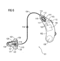
- FIG. 6 shows a behind-the-ear hearing device 101, which comprises a housing part 102 that can be worn behind the ear, an earmold piece 103 that can be worn in the ear, and a receiver tube 104 that connects the housing part 102 to the earmold piece 103.
- a microphone 105 is present. The electrical input signal output by the microphone 105 is supplied to a signal processing and amplifier unit 106 to compensate for the hearing loss of a user.
- the resulting electrical output signal is supplied via electrical lines 123, 124 and 125 to a receiver 107, which converts the electrical output signal into an acoustic output signal and emits via a sound channel 108 into the auditory canal of the user.
- a ventilation channel is used to ventilate the auditory canal volume enclosed by the earmold 103 (Vent) 109.
- the hearing device 101 comprises a user-operable control element 110 and a voltage source in the form of a battery 126 for supplying power to the electronic components of the hearing aid 101.
- the earphone tube 104 is made of a relatively rigid plastic material.
- the handset tube 104 may be e.g. be adapted under heat to the individual anatomical conditions of the user. Following such an adjustment, it is elastically deformable.
- the receiver tube 104 encloses the electrical lines 124 for the electrical connection of the receiver 107 with the signal processing and amplifier unit 106.
- the earphone tube 104 is detachably connected both to the earmold piece 103 and to the housing part 102.
- the releasable electrical and mechanical connection via contact pins 116 and 120, which are inserted into corresponding sockets 118 and 122 in the housing part 102 and the earmold 103.
- the plug member 115 is floatingly mounted in the vibration damping material consisting of damping element 112.
- the socket part 117 with the bushing 118 in a corresponding damping element 111 at the end of the housing part 102 is floatingly mounted.
- the transmission of mechanical vibrations from the receiver tube 104 to the housing part 102 is largely prevented.
- the second end of the receiver tube 104 is correspondingly decoupled from the earmold 103 in terms of vibration technology.
- the plug part 119 at the opposite end of the receiver tube 104 with the plug 120 directly, ie without vibration suppressing measures attached to the handset tube 104.
- the bushing part 121 is floatingly mounted with the sleeve 122 in the damping element 113 of vibration-damping material. As a result, the transmission of mechanical vibrations is suppressed by the earmold on the handset tube 104.
- a damping element 114 is present in the tube 104. This divides the listener tube 104 into two sections which are connected to each other in a vibration-damping manner.
- a user-friendly and easy-to-maintain hearing aid 101 with the three detachably interconnected components earmold 103, earphone tube 104 and housing part 102 is created by the measures shown, in which the transmission of mechanical vibrations of the earmold 103 to the housing part 102 is largely prevented.
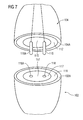
- FIG. 7 shows a detailed view of the plug connection between the receiver tube 104 and the housing part 102.
- the plug part 115 At the end of the receiver tube 104 is the plug part 115 with the two contact pins 116 and 116A.
- the plug part 115 is separated from the plastic material of the receiver tube 104 by means of the damping unit 112 made of vibration-damping material.
- the plug part 115 is floatingly mounted in the damping element 112. There is thus no direct connection between the plug part 115 and the plastic material of the outer shell 104A of the socket part 104.
- the socket part 117 with the two bushes 118 and 118A is separated by the damping element 111 from the housing of the housing part 102 and in particular in the Damping element 111 floating.
Abstract
Description
Die vorliegende Erfindung betrifft eine Hörvorrichtung mit wenigstens einem hinter dem Ohr tragbaren Gehäuseteil, einem in dem Ohr tragbaren Ohrpassstück, einem das Gehäuseteil mit dem Ohrpassstück verbindenden Hörerschlauch, einem Mikrofon zur Aufnahme eines akustischen Eingangssignals und Abgabe eines elektrischen Eingangssignals, einer Signalverarbeitungs- und Verstärkereinheit zur Verarbeitung und Verstärkung des elektrischen Eingangssignals und zur Abgabe eines elektrischen Ausgangssignals und einem in dem Ohrpassstück angeordneten Hörer zur Wandlung des elektrischen Ausgangssignals in ein akustisches Ausgangssignal. Darüber hinaus betrifft die Erfindung einen Hörerschlauch für eine entsprechende Hörvorrichtung.The present invention relates to a hearing device with at least one behind the ear portable housing part, an earmold in the ear, a the housing part with the earmold connecting earphone tube, a microphone for receiving an acoustic input signal and output of an electrical input signal, a signal processing and amplifier unit for Processing and amplification of the electrical input signal and for outputting an electrical output signal and a receiver arranged in the earmold for converting the electrical output signal into an acoustic output signal. Moreover, the invention relates to a receiver tube for a corresponding hearing device.
Bei einem Hinter-dem-Ohr-Hörgerät mit einem hinter dem Ohr tragbaren Gehäuseteil und einem in dem Ohr tragbaren Ohrpassstück (Otoplastik) wird der Schall durch den so genannten Hörerschlauch vom Hörgerät ins Ohr des Patienten transportiert. Bei einem Hinter-dem-Ohr-Hörgerät, welches mit einem in dem Ohrpassstück angeordneten (externen) Hörer ausgestattet ist, verläuft durch den Hörerschlauch die elektrische Leitung, mit der der Hörer an das Hörgerät angekoppelt ist.In a behind-the-ear hearing aid having a housing part that can be worn behind the ear and an earmold (earmold) that can be worn in the ear, the sound is transported by the so-called receiver tube from the hearing device into the patient's ear. In a behind-the-ear hearing device, which is equipped with a (external) earphone arranged in the earmold, the electrical line through which the earphone is coupled to the hearing device runs through the earphone tube.
Da das Hörgerät einschließlich Hörerschlauch und gegebenenfalls Hörer bzw. Otoplastik am Körper des Hörgeräteträgers anliegen, kann Körperschall vom Hörgeräteträger zum Hörgerät übertragen werden. Die Einkopplung des Körperschalls erfolgt entweder direkt vom Körper des Hörgeräteträgers zum Hörgerät selbst oder über den Hörer bzw. den Hörerschlauch zum Hörgerät verursacht durch Vibrationen des Hörers oder sonstige Ereignisse. Umgekehrt kann sich der Körperschall aber auch vom Hörgerät über den Hörerschlauch und den Hörer bzw. die Otoplastik zum Gehör ausbreiten. In jedem Fall verfälscht der eingekoppelte Körperschall das Nutzsignal.Since the hearing aid, including the receiver tube and possibly the earpiece or the earmold, rest on the body of the hearing device wearer, structure-borne noise can be transmitted from the hearing aid wearer to the hearing aid. The coupling of structure-borne noise is carried out either directly from the body of the hearing aid wearer to the hearing aid itself or via the handset or the listener tube to the hearing aid caused by vibrations of the listener or other events. Conversely, the structure-borne noise can also spread to the hearing from the hearing aid via the tube and the earpiece or earmold. In any case, the coupled structure-borne noise falsifies the useful signal.
Hinter dem Ohr tragbare Hörgeräte mit in das Ohrpassstück verlagertem Hörer, so genannte RIC-(Receiver-In-Canal) Geräte, sind trotz des verhältnismäßig großen Abstandes zwischen dem Hörer und dem Mikrofon rückkopplungsanfällig. Dies resultiert aus der häufig relativ starren Verbindung des Hörgerätegehäuses mit dem Ohrpassstück, über das die Vibrationen des Hörers über den Hörerschlauch mechanisch zurückgekoppelt werden.Behind the ear portable hearing aids with displaced in the earmold earpiece, so-called RIC (Receiver-in-Canal) devices are despite the relatively large distance between the handset and the microphone feedback-prone. This results from the often relatively rigid connection of the hearing aid housing with the earmold, over which the vibrations of the listener are mechanically fed back via the tube.
Darüber hinaus treten mechanische Rückkopplungen vermehrt auch bei Hinter-dem-Ohr-Hörgeräten mit einem Hörerschlauch zur Schallleitung zwischen dem Hörgerätegehäuse und dem Ohrpassstück auf, bei denen der Hörerschlauch zumindest teilweise auch die Funktion eines Tragbügels zum Tragen des Hörhilfegerätes hinter dem Ohr übernimmt. Hierfür werden gewöhnlich an die Anatomie des Ohres angepasste, vorgeformte Hörerschläuche verwendet, die für diesen Verwendungszweck eine bestimmte Steifigkeit aufweisen müssen und daher mechanische Schwingungen (Körperschall) verhältnismäßig gut übertragen.In addition, mechanical feedback increasingly occurs even in behind-the-ear hearing aids with a tube to the sound conductor between the hearing aid housing and the earmold on which the tube takes over at least partially the function of a support bracket for carrying the hearing aid behind the ear. For this purpose, usually adapted to the anatomy of the ear, preformed handset tubes are used, which must have a certain stiffness for this purpose and therefore transmit relatively well mechanical vibrations (structure-borne noise).
Zur Vermeidung von Rückkopplungen ist es bisher möglich, die Wirkung des Körperschalls auf das eigentliche Hörgerät zu reduzieren. Hierbei wird die Wandstärke des Gehäuses des Hörgeräts möglichst dick ausgelegt, um dämpfende Wirkung zu erzielen. Außerdem werden alle inneren Aufhängungsteile so ausgelegt, dass sie Eigenschwingungen und Körperschall dämpfen bzw. ausfiltern. Bekannte Maßnahmen zur Unterdrückung von Rückkopplungen sind insbesondere die schwingungsdämpfende Lagerung des Hörers oder des Mikrofons.To avoid feedback, it has hitherto been possible to reduce the effect of structure-borne noise on the actual hearing device. Here, the wall thickness of the housing of the hearing aid is designed to be as thick as possible in order to achieve a damping effect. In addition, all internal suspension parts are designed so that they dampen or filter out natural vibrations and structure-borne noise. Known measures for suppressing feedback are, in particular, the vibration-damping mounting of the receiver or the microphone.
Durch eine reduzierte Verstärkung bzw. Bandbreite kann man den Rückkopplungsanteil so weit dämpfen, dass ein elektronischer Feedback-Kompensator ein Rückkopplungspfeifen des Hörgerätes verhindern kann. Größere Hörverluste können damit allerdings nicht mehr versorgt werden.A reduced gain or bandwidth can attenuate the feedback component to such an extent that an electronic feedback compensator can prevent a feedback whistling of the hearing aid. Larger hearing losses, however, can not be supplied with it.
Aus der
Aus der
Aus der
Darüber hinaus ist in der Druckschrift
Ferner ist aus der Patentschrift
Aufgabe der vorliegenden Erfindung ist es, Rückkopplungen bei einer hinter dem Ohr tragbaren Hörvorrichtung mit einem in dem Ohr tragbaren Ohrpassstück zu vermeiden.The object of the present invention is to avoid feedback in a hearing device worn behind the ear with an earmold that can be worn in the ear.
Diese Aufgabe wird gelöst durch eine Hörvorrichtung mit den Merkmalen gemäß Patentanspruch 1 sowie durch einen Hörerschlauch mit den Merkmalen gemäß Patentanspruch 17.This object is achieved by a hearing device with the features according to claim 1 and by a receiver tube with the features according to
In vorteilhafter Weise wird durch einen gedämpften Hörerschlauch erreicht, dass soweit wie möglich keine Signalverfälschung des Schalls hervorgerufen wird, der vom Hörgerät ins Ohr übertragen wird. Durch die Erfindung wird auch die Übertragung mechanischer Schwingungen von dem Ohrpassstück über den Hörerschlauch zu dem Gehäuseteil zumindest weitgehend unterbunden. Damit treten Rückkopplungen im Vergleich zu einer Hörvorrichtung ohne die genannten schwingungsdämpfenden Maßnahmen wesentlich seltener auf. Die Erfindung ist insbesondere dann von Vorteil, wenn der Hörerschlauch zwischen dem Ohrpassstück und dem Gehäuseteil einstückig und verhältnismäßig starr ausgebildet ist und auch zur Halterung und Fixierung der Hörvorrichtung am Ohr eines Benutzers dient.Advantageously, it is achieved by a dampened receiver tube that as far as possible no signal distortion of the sound is caused, which is transmitted from the hearing aid to the ear. Due to the invention, the transmission of mechanical vibrations from the earmold via the tube to the housing part is at least largely prevented. Thus, in comparison to a hearing device without the said vibration-damping measures, feedback occurs much less frequently. The invention is particularly advantageous if the receiver tube between the earmold and the housing part is integrally formed and relatively rigid and also used to hold and fix the hearing on the ear of a user.
Weiterhin ist die Erfindung insbesondere dann von Vorteil, wenn durch die Hörvorrichtung eine so genannte "geschlossene Versorgung" bewirkt wird. Dabei ist das durch das Ohrpassstück eingeschlossene Gehörgangvolumen weitgehend luft- und schalldicht von der äußeren Umgebung des Ohrs abgetrennt, so dass akustische Rückkopplungen zwischen dem Hörer und dem Mikrofon lediglich eine untergeordnete Rolle spielen. Mechanische Rückkopplungen fallen bei einer derartigen Anordnung sehr viel stärker ins Gewicht.Furthermore, the invention is particularly advantageous when a so-called "closed supply" is effected by the hearing device. In this case, the auditory canal volume enclosed by the earmold is largely air-tight and soundproof separated from the outer environment of the ear, so that acoustic feedback between the listener and the microphone only play a minor role. Mechanical feedback is much more important in such an arrangement.
Es bestehen mehrere Möglichkeiten zur Anordnung von Dämpfungselementen, die die Schallübertragung von dem Ohrpassstück auf das Gehäuseteil einschränken. Einerseits kann wenigstens ein Dämpfungselement an oder in dem Hörerschlauch angeordnet werden. Vorzugsweise besitzt das Schalldämpfungselement hierfür ein Drahtgeflecht. Wird das Drahtgeflecht bei der Herstellung des Schlauchs mit eingelegt, so können dadurch gezielt bestimmte Frequenzen gedämpft werden. Je nach Art des Geflechts kann auch eine breitbandige Dämpfung erfolgen. Durch das Drahtgeflecht können auch Signale übertragen werden, ohne dass diese selbst die Schwingungen übertragen.There are several options for the arrangement of damping elements that limit the transmission of sound from the earmold on the housing part. On the one hand, at least one damping element can be arranged on or in the receiver tube. Preferably, the sound damping element for this purpose has a wire mesh. If the wire mesh is inserted during the production of the hose, it is possible to specifically dampen certain frequencies. Depending on the type of braid, a broadband damping can also take place. Through the wire mesh and signals can be transmitted without these themselves transmit the vibrations.
Darüber hinaus kann das Schalldämpfungselement zumindest teilweise aus geschäumtem Material bestehen. Dieses geschäumte Material reduziert die Steifigkeit des Hörschlauchs sowohl in Längs- als auch in Querrichtung, so dass sowohl Longitudinal- als auch Transversalwellen des Hörerschlauchs gedämpft werden.In addition, the sound-damping element may at least partially consist of foamed material. This foamed material reduces the stiffness of the hearing tube in both the longitudinal and transverse directions so that both longitudinal and transverse waves of the tube are damped.
Das Schalldämpfungselement kann ferner in Längsrichtung des Hörerschlauchs ziehharmonikaartig ausgebildet sein. Damit können Schubkräfte längs des Hörerschlauchs und somit Longitudinalwellen abgefangen werden.The sound-damping element may also be accordion-like in the longitudinal direction of the listener tube. This shear forces along the Hörerschlauchs and thus longitudinal waves can be intercepted.
Des Weiteren kann das Schalldämpfungselement auch ein S-förmiges Schlauchstück aufweisen. Auch dadurch können Schubkräfte längs des Hörerschlauchs reduziert werden.Furthermore, the sound-damping element can also have an S-shaped hose piece. This also shear forces can be reduced along the Hörerschlauchs.
Die oben beschriebenen Schalldämpfungselemente können in geeigneter Weise auch miteinander kombiniert werden, so dass sich der Dämpfungseffekt entsprechend erhöhen lässt.The sound-damping elements described above can also be combined with each other in a suitable manner, so that the damping effect can be correspondingly increased.
Es wurde bereits angedeutet, dass der Hörerschlauch im Zusammenhang mit einem Hörgerät verwendet werden kann. Der Einsatz eines erfindungsgemäßen Hörerschlauchs bei anderen Hörvorrichtungen wie Headsets, Kopfhörern und dergleichen ist jedoch ebenso nutzbringend.It has already been indicated that the receiver tube can be used in conjunction with a hearing aid. However, the use of a tube according to the invention in other hearing devices such as headsets, headphones and the like is also beneficial.
Vorzugsweise ist der Hörerschlauch sowohl an dem Ohrpassstück als auch an dem Gehäuseteil lösbar befestigt. Dies ermöglicht z.B. im Reparaturfall einen einfachen Austausch. Über eine Steckverbindung kann in einfacher Weise sowohl eine mechanische als auch eine elektrische Verbindung zwischen dem Hörerschlauch und dem Ohrpassstück bzw. dem Gehäuseteil erfolgen. Die Enden des Hörerschlauchs können als Stecker oder als Buchse ausgebildet sein. Erfindungsgemäß erfolgt vorzugsweise eine schwingungsdämpfende Lagerung des Steckers bzw. der Buchse an dem jeweiligen Ende des Hörerschlauchs. Darüber hinaus ist es jedoch auch möglich, dass ein Dämpfungselement in dem Bereich des Hörerschlauchs zwischen den beiden Enden eingefügt wird. Außer an dem Hörerschlauch können Dämpfungselemente auch am Ohrpassstück oder dem Gehäuseteil angebracht sein. Für eine bevorzugte lösbare Verbindung mit dem Hörerschlauch weist das Ohrpassstück bzw. das Gehäuseteil jeweils einen Stecker bzw. eine Buchse auf. Auch diese sind gemäß der Erfindung vorteilhaft schwingungsdämpfend gegenüber dem Ohrpassstück bzw. dem Gehäuseteil gelagert.Preferably, the receiver tube is releasably secured both to the ear tip and to the housing part. This allows, for example, in case of repair a simple exchange. Both a mechanical and an electrical connection between the receiver tube and the earmold or the housing part can be done in a simple manner via a plug connection. The ends of the listener tube may be formed as a plug or a socket. According to the invention is preferably a vibration-damping mounting of the plug or the Bushing at the respective end of the tube. In addition, however, it is also possible that a damping element is inserted in the region of the listener tube between the two ends. In addition to the receiver tube damping elements can also be attached to the earmold or the housing part. For a preferred releasable connection with the receiver tube, the earmold piece or the housing part in each case has a plug or a socket. These are also advantageous according to the invention vibration damping against the ear mold or the housing part stored.
Die von dem Ohrpassstück über den Hörerschlauch auf das Gehäuseteil übertragenen Schwingungen werden bereits merklich gedämpft, wenn lediglich an einer Stelle der betreffenden Hörvorrichtung, z.B. im Bereich einer Buchse an einem Ende des Gehäuseteils, schwingungsdämpfende Maßnahmen getroffen werden. Eine weitere Reduzierung der von dem Ohrpassstück ausgehenden Schwingungen kann dadurch erreicht werden, dass entsprechende Dämpfungsmaßnahmen an mehreren Stellen, z.B. sowohl im Bereich einer Buchse am Gehäuseteil als auch im Bereich einer Buchse am Ohrpassstück oder sowohl im Bereich einer Buchse als auch im Bereich des damit verbindbaren Steckers getroffen werden.The vibrations transmitted from the eartip to the housing part via the earphone tube are already appreciably attenuated if only at one location of the hearing device in question, e.g. in the region of a socket at one end of the housing part, vibration-damping measures are taken. A further reduction in the vibrations emanating from the earmold can be achieved by using corresponding attenuation measures in several places, e.g. Both in the area of a socket on the housing part and in the region of a socket on the earmold piece or both in the area of a socket and in the region of the plug which can be connected thereto.
Selbstverständlich können schwingungsdämpfende Elemente gemäß der Erfindung im Übergangsbereich zwischen dem Hörerschlauch und dem Gehäuseteil oder zwischen dem Hörerschlauch und dem Ohrpassstück auch bei einer festen, das heißt nicht lösbaren Verbindung zwischen den Bauteilen vorhanden sein.Of course, vibration damping elements according to the invention in the transition region between the listener tube and the housing part or between the listener tube and the earmold even with a solid, that is not detachable connection between the components may be present.
Die Erfindung wird nachfolgend durch Ausführungsbeispiele anhand der Zeichnungen näher erläutert. Es zeigen:
- Figur 1
- ein Hinter-dem-Ohr-Hörgerät gemäß dem Stand der Technik;
Figur 2- ein Hinter-dem-Ohr-Hörgerät mit externem Hörer und einem Hörerschlauch gemäß einer ersten Ausführungsform der vorliegenden Erfindung;
Figur 3- einen Hörerschlauch gemäß einer zweiten Ausführungsform;
Figur 4- einen Hörerschlauch gemäß einer dritten Ausführungsform; und
- Figur 5
- einen Hörerschlauch gemäß einer vierten Ausführungsform.
- Figur 6
- ein Hörvorrichtung mit einem hinter dem Ohr tragbaren Gehäuseteil, einem in dem Ohr tragbaren Ohrpassstück und einem das Gehäuseteil mit dem Ohrpassstück verbindenden Hörerschlauch und
- Figur 7
- eine Detail-Zeichnung für eine lösbare Verbindung zwischen dem Hörerschlauch und dem Gehäuseteil.
- FIG. 1
- a behind-the-ear hearing aid according to the prior art;
- FIG. 2
- a behind-the-ear hearing aid with an external handset and a listener tube according to a first embodiment of the present invention;
- FIG. 3
- a receiver tube according to a second embodiment;
- FIG. 4
- a receiver tube according to a third embodiment; and
- FIG. 5
- a receiver tube according to a fourth embodiment.
- FIG. 6
- a hearing device with a behind the ear portable housing part, a portable in the ear earmold and the housing part with the earmold connecting earphone tube and
- FIG. 7
- a detail drawing for a detachable connection between the listener tube and the housing part.
Die nachfolgend näher geschilderten Ausführungsbeispiele stellen bevorzugte Ausführungsformen der vorliegenden Erfindung dar.The embodiments described in more detail below represent preferred embodiments of the present invention.
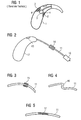
Zum besseren Verständnis der Erfindung wird zunächst anhand von Figur 1 ein bekanntes Dämpfungssystem kurz erläutert. Ein Gehäuse 1 eines Hinter-dem-Ohr-Hörgeräts besitzt im Inneren angespritzte Strukturen 2, die zur Fixierung eines Hörers 3 dienen. Damit der Hörer 3 nicht starr mit diesen Strukturen 2 in Verbindung steht, werden ein oder mehrere Dämpfungselemente 4 zwischen den Hörer 3 und die Struktur 2 bzw. das Hörgerätegehäuse 1 gebracht. Dadurch kann größtenteils vermieden werden, dass Körperschall praktisch ungedämpft vom Hörer 3 über das Hörgerätegehäuse 1 zu dem eingebauten Mikrofon 5 gelangt. Auf diese Weise lassen sich somit bei einem Hörgerät mit eingebautem Hörer 3 Rückkopplungen größtenteils vermeiden.For a better understanding of the invention, a known damping system will first be briefly explained with reference to FIG. A housing 1 of a behind-the-ear hearing device has molded-in
Bei einem Hörgerät mit externem Hörer 10 gemäß Figur 2 können Vibrationen des Hörers 10 über einen Hörerschlauch 11 zum Hörgerätegehäuse 12 übertragen werden. Das in das Hörgerätegehäuse 12 eingebaute Mikrofon 13 nimmt diese übertragenen Vibrationen als Körperschall auf, so dass es unter Umständen zu störenden Rückkopplungen kommt. Um dies zu vermeiden, wird nun erfindungsgemäß ein Dämpfungselement 14 in und/oder an dem Hörerschlauch 11 angebracht. Dieses Dämpfungselement 14 bewirkt, dass Körperschall auf seinem Übertragungsweg vom Hörer 10 zum Mikrofon 13 zusätzlich gedämpft wird.In a hearing aid with
Das Dämpfungselement 14 besteht beispielsweise aus einer zusätzlichen Masse, die die Schwingungen des Hörerschlauchs 11 reduziert. Entsprechend einer anderen Variante des gedämpften Hörerschlauchs 11 ist das Dämpfungselement 14 als geschäumter Schlauchabschnitt in den Hörerschlauch 11 integriert. Dieser geschäumte Abschnitt überträgt dann kaum mehr Schwingungen vom einen Teil des Hörerschlauchs 11 zum anderen Teil.The damping
Eine zweite Ausführungsform des erfindungsgemäßen Hörerschlauchs ist in Figur 3 wiedergegeben. Demnach ist der Hörerschlauch in einem Mittelabschnitt wie eine Ziehharmonika 15 ausgebildet. Über diesen ziehharmonikaartigen Abschnitt werden Longitudinalwellen, aber auch Transversalwellen kaum übertragen.A second embodiment of the receiver tube according to the invention is shown in FIG. Accordingly, the listener tube is formed in a central portion like an
Eine sehr einfache Variante eines erfindungsgemäßen Dämpfungselements besteht darin, dass ein Mittelabschnitt 16 entsprechend Figur 4 S-förmig gestaltet ist. Auch dieser S-förmige Abschnitt 16 dämpft Schubkräfte in dem Hörerschlauch 11.A very simple variant of a damping element according to the invention is that a
In dem vierten Ausführungsbeispiel gemäß Figur 5 ist in das Innere des Hörerschlauchs bei der Herstellung ein Drahtgeflecht 17 in einem Teilbereich des Hörerschlauchs 11 eingelegt. Je nach Härte und Struktur des Drahtgeflechts und auch des verwendeten Kunststoffs/Gummi wird der erfindungsgemäße Hörerschlauch 11 die gewünschten Frequenzen filtern und dämpfen.In the fourth exemplary embodiment according to FIG. 5, a
Bei dem im Zusammenhang mit Figur 2 erläuterten Hörgerät mit externem Hörer 10 reduziert der gedämpfte Hörerschlauch 11, in dem die elektrischen Leitungen zum Hörer 10 laufen, die akustischen Rückkopplungen vom Hörer 10 zum Mikrofon 13. Es besteht aber auch bei einem Hörgerät mit integriertem Hörer 3 entsprechend Figur 1 der Bedarf den über den Hörerschlauch übertragenen Körperschall zu dämpfen. Auch bei derartigen Hörgeräten kommt es nämlich zu Signalverfälschungen, wenn der Nutzschall, der vom Hörer 3 durch den Hörerschlauch ins Ohr geleitet wird, durch Störschallanteile, die über die Hörerschlauchwand ebenfalls ins Ohr gelangen, verfälscht wird. Hier lässt sich der gedämpfte Hörerschlauch entsprechend der vorliegenden Erfindung ebenfalls nutzbringend einsetzen.In the case of the hearing device with
Die oben im Detail dargestellten Ausführungsformen können einzeln oder in Kombination verwendet werden. Somit lassen sich für eine oder mehrere Frequenzen die gewünschten Dämpfungsgrade erzielen.The embodiments described in detail above may be used singly or in combination. Thus, the desired damping levels can be achieved for one or more frequencies.
Figur 6 zeigt ein Hinter-dem-Ohr-Hörgerät 101, das ein hinter dem Ohr tragbares Gehäuseteil 102, ein in dem Ohr tragbares Ohrpassstück 103 sowie einen das Gehäuseteil 102 mit dem Ohrpassstück 103 verbindenden Hörerschlauch 104 umfasst. Zur Aufnahme eines akustischen Eingangssignals und Wandlung des akustischen Eingangssignals in ein elektrisches Eingangssignal ist ein Mikrofon 105 vorhanden. Das von dem Mikrofon 105 abgegebene elektrische Eingangssignal wird zur Kompensation des Hörverlustes eines Benutzers einer Signalverarbeitungs- und Verstärkereinheit 106 zugeführt. Das daraus hervorgehende elektrische Ausgangssignal ist über elektrische Leitungen 123, 124 und 125 einem Hörer 107 zugeführt, der das elektrische Ausgangssignal in ein akustisches Ausgangssignal wandelt und über einen Schallkanal 108 in den Gehörgang des Benutzers abgibt. Zur Belüftung des von dem Ohrpassstück 103 eingeschlossenen Gehörgangvolumens dient ein Ventilationskanal (Vent) 109. Weiterhin umfasst das Hörgerät 101 ein von dem Benutzer betätigbares Bedienelement 110 sowie eine Spannungsquelle in Form einer Batterie 126 zur Spannungsversorgung der elektronischen Komponenten des Hörgerätes 101.FIG. 6 shows a behind-the-
Um einen guten Halt des Hörgerätes 101 am Ohr zu gewährleisten, ist der Hörerschlauch 104 aus einem verhältnismäßig steifen Kunststoffmaterial gefertigt. Der Hörerschlauch 104 kann z.B. unter Wärmeeinwirkung an die individuellen anatomischen Gegebenheiten des Benutzers angepasst werden. Im Anschluss an eine derartige Anpassung ist er elastisch verformbar. Der Hörerschlauch 104 umschließt die elektrischen Leitungen 124 zur elektrischen Verbindung des Hörers 107 mit der Signalverarbeitungs- und Verstärkereinheit 106.In order to ensure a good grip of the
Damit der an die anatomischen Gegebenheiten angepasste Hörerschlauch 104 seine Form beibehält, ist eine bestimmte Steifigkeit erforderlich. Dies hat jedoch den Nachteil, dass von dem Hörer 107 auf das Ohrpassstück 103 übertragene mechanische Schwingungen über den Hörerschlauch 104 zum Gehäuseteil 102 weitergeleitet werden, die dadurch auch zu dem Mikrofon 105 gelangen können. Dadurch entstehen unerwünschte mechanische Rückkopplungen.In order for the tube adapted to the
Bei dem Hörgerät 101 gemäß dem Ausführungsbeispiel ist der Hörerschlauch 104 sowohl mit dem Ohrpassstück 103 als auch mit dem Gehäuseteil 102 lösbar verbunden. Die lösbare elektrische und mechanische Verbindung erfolgt über Kontaktstifte 116 bzw. 120, die in entsprechende Buchsen 118 bzw. 122 in dem Gehäuseteil 102 bzw. dem Ohrpassstück 103 gesteckt werden. Zur Schwingungsdämpfung gemäß der Erfindung ist das Steckerteil 115 schwimmend in dem aus vibrationsdämpfendem Material bestehenden Dämpfungselement 112 gelagert. Ebenso ist auch das Buchsenteil 117 mit der Buchse 118 in einem entsprechenden Dämpfungselement 111 am Ende des Gehäuseteils 102 schwimmend gelagert. Durch die gezeigte Anordnung wird die Übertragung mechanischer Schwingungen von dem Hörerschlauch 104 auf das Gehäuseteil 102 weitestgehend unterbunden. Auch das zweite Ende des Hörerschlauchs 104 ist in entsprechender Weise schwingungstechnisch von dem Ohrpassstück 103 entkoppelt. Im Unterschied zu der Verbindung mit dem Gehäuseteil 102 ist bei dem gegenüberliegenden Ende des Hörerschlauchs 104 das Steckerteil 119 mit dem Stecker 120 jedoch direkt, d.h. ohne schwingungsunterdrückende Maßnahmen, an dem Hörerschlauch 104 befestigt. Bei dem Ohrpassstück 103 ist jedoch analog zum Gehäuseteil 102 das Buchsenteil 121 mit der Buchse 122 schwimmend in dem Dämpfungselement 113 aus schwingungsdämpfendem Material gelagert. Hierdurch wird die Übertragung mechanischer Schwingungen von dem Ohrpassstück auf den Hörerschlauch 104 unterbunden.In the
Als weitere schwingungsdämpfende Maßnahme ist in dem Hörerschlauch 104 ein Dämpfungselement 114 vorhanden. Dieses unterteilt den Hörerschlauch 104 in zwei Teilabschnitte, die schwingungsdämpfend miteinander verbunden sind.As a further vibration-damping measure, a damping element 114 is present in the
Insgesamt wird durch die gezeigten Maßnahmen ein bedien- und wartungsfreundliches Hörgerät 101 mit den drei lösbar miteinander verbundenen Komponenten Ohrpassstück 103, Hörerschlauch 104 und Gehäuseteil 102 geschaffen, bei dem die Übertragung mechanischer Schwingungen von dem Ohrpassstück 103 auf das Gehäuseteil 102 weitestgehend unterbunden ist.Overall, a user-friendly and easy-to-maintain
Figur 7 zeigt eine Detailansicht der Steckverbindung zwischen dem Hörerschlauch 104 und dem Gehäuseteil 102. Am Ende des Hörerschlauchs 104 befindet sich das Steckerteil 115 mit den beiden Kontaktstiften 116 und 116A. Das Steckerteil 115 ist mittels der Dämpfungseinheit 112 aus schwingungsdämpfendem Material von dem Kunststoffmaterial des Hörerschlauchs 104 getrennt. Insbesondere ist das Steckerteil 115 schwimmend in dem Dämpfungselement 112 gelagert. Es besteht somit keine direkte Verbindung zwischen dem Steckerteil 115 und dem Kunststoffmaterial der äußeren Hülle 104A des Buchsenteils 104. Entsprechend ist auch das Buchsenteil 117 mit den beiden Buchsen 118 und 118A durch das Dämpfungselement 111 von dem Gehäuse des Gehäuseteils 102 getrennt und insbesondere in dem Dämpfungselement 111 schwimmend gelagert. Beim Herstellen der elektrischen und mechanischen Verbindung zwischen dem Hörerschlauch 104 und dem Gehäuseteil 102 durch Einführen der Stifte 116 und 116A in die Buchsen 118 bzw. 18A entsteht keine direkte Verbindung zwischen der äußeren Hülle 104A des Buchsenteils 104 und dem Gehäuse 102A des Gehäuseteils 102. Die Übertragung mechanischer Schwingungen von dem Hörerschlauch 104 auf das Gehäuseteil 102 wird somit durch die Dämpfungselemente 111 und 112 weitgehend unterbunden.FIG. 7 shows a detailed view of the plug connection between the
Claims (17)
gekennzeichnet durch
wenigstens ein Dämpfungselement (14, 15, 16, 17, 111, 112, 113, 114), das in oder an dem Hörerschlauch (11, 104) angeordnet ist, zur Dämpfung mechanischer Schwingungen, die über den Hörerschlauch (11, 104) zwischen dem Ohrpassstück (103) und dem Gehäuseteil (102) übertragen werden.A receiver tube (11, 104) for connecting a housing part (102) that can be worn behind the ear to an earmold piece (103) of a hearing device (101) according to any one of claims 1 to 16 that is portable in the ear.
marked by
at least one damping element (14, 15, 16, 17, 111, 112, 113, 114) disposed in or on the tube (11, 104) for damping mechanical vibrations transmitted through the tube (11, 104) between the earmold (103) and the housing part (102) are transmitted.
Applications Claiming Priority (1)
| Application Number | Priority Date | Filing Date | Title |
|---|---|---|---|
| DE102005036849A DE102005036849A1 (en) | 2005-08-04 | 2005-08-04 | Receiver tube with damping element and corresponding hearing device |
Publications (1)
| Publication Number | Publication Date |
|---|---|
| EP1750480A1 true EP1750480A1 (en) | 2007-02-07 |
Family
ID=37156020
Family Applications (1)
| Application Number | Title | Priority Date | Filing Date |
|---|---|---|---|
| EP06016347A Withdrawn EP1750480A1 (en) | 2005-08-04 | 2006-08-04 | Hearing aid with damping element |
Country Status (3)
| Country | Link |
|---|---|
| US (1) | US7783068B2 (en) |
| EP (1) | EP1750480A1 (en) |
| DE (1) | DE102005036849A1 (en) |
Cited By (5)
| Publication number | Priority date | Publication date | Assignee | Title |
|---|---|---|---|---|
| WO2008015295A2 (en) | 2006-10-11 | 2008-02-07 | Phonak Ag | Hearing device |
| EP2015605A2 (en) | 2007-07-09 | 2009-01-14 | Siemens Audiologische Technik GmbH | Hearing aid |
| EP2456235A1 (en) * | 2010-11-17 | 2012-05-23 | Yamaichi Electronics Deutschland GmbH | Hearing aid, connector, use of a connector and system for connecting a hearing aid with a cable |
| DE102011006720A1 (en) | 2011-04-04 | 2012-10-04 | Siemens Medical Instruments Pte. Ltd. | Ear canal insert with a filter element |
| DE102019202651A1 (en) | 2019-02-27 | 2020-01-23 | Sivantos Pte. Ltd. | Sound tube and BTE hearing aid |
Families Citing this family (14)
| Publication number | Priority date | Publication date | Assignee | Title |
|---|---|---|---|---|
| US8333260B1 (en) * | 2005-04-25 | 2012-12-18 | Hall John A | Deep insertion vented earpiece system |
| DE102007033289A1 (en) * | 2007-07-17 | 2009-01-22 | Siemens Audiologische Technik Gmbh | Arrangement with carrying hook for hearing aids and associated method |
| DE102007052648A1 (en) * | 2007-11-05 | 2009-05-07 | Siemens Medical Instruments Pte. Ltd. | Hearing aid, in particular BTE hearing aid |
| DE102008007553A1 (en) * | 2008-02-05 | 2009-08-13 | Siemens Medical Instruments Pte. Ltd. | Hearing aid with acoustic damper |
| EP2117258A1 (en) | 2008-05-07 | 2009-11-11 | Cochlear Limited | Cable length adjustment in hearing aid devices |
| US9781514B2 (en) | 2010-03-25 | 2017-10-03 | K&E Holdings, LLC | Stereo audio headphone apparatus |
| US9161131B2 (en) * | 2010-03-25 | 2015-10-13 | K&E Holdings, LLC | Stereo audio headphone apparatus for a user having a hearing loss and related methods |
| US8406448B2 (en) * | 2010-10-19 | 2013-03-26 | Cheng Uei Precision Industry Co., Ltd. | Earphone with rotatable earphone cap |
| DK2512152T3 (en) | 2011-04-13 | 2014-02-03 | Oticon As | Hearing aid with two or more microphones |
| US20120288130A1 (en) * | 2011-05-11 | 2012-11-15 | Infineon Technologies Ag | Microphone Arrangement |
| CN104378708A (en) * | 2014-11-11 | 2015-02-25 | 苏州立人听力器材有限公司 | Hearing aid binaural receiver with damper |
| US10079009B2 (en) | 2015-03-13 | 2018-09-18 | Woojer Ltd. | System for providing vibrations remotely from a vibrating transducer |
| EP4117309A1 (en) * | 2017-12-28 | 2023-01-11 | Starkey Laboratories, Inc. | Cable for a receiver-in-canal hearing device |
| GB201907610D0 (en) | 2019-05-29 | 2019-07-10 | Pss Belgium Nv | Loudspeaker |
Citations (8)
| Publication number | Priority date | Publication date | Assignee | Title |
|---|---|---|---|---|
| GB2039191A (en) * | 1978-12-15 | 1980-07-30 | Danavox As | Hookshaped part of a behind-the ear hearing aid |
| DE3141921A1 (en) | 1981-10-22 | 1983-05-05 | Robert Bosch Gmbh, 7000 Stuttgart | Hearing aid |
| DE8905756U1 (en) * | 1989-05-08 | 1989-07-13 | Siemens Ag, 1000 Berlin Und 8000 Muenchen, De | |
| US5606621A (en) * | 1995-06-14 | 1997-02-25 | Siemens Hearing Instruments, Inc. | Hybrid behind-the-ear and completely-in-canal hearing aid |
| DE29801567U1 (en) | 1998-01-30 | 1998-04-16 | Siemens Audiologische Technik | Hearing aid portable behind the ear |
| US6275596B1 (en) | 1997-01-10 | 2001-08-14 | Gn Resound Corporation | Open ear canal hearing aid system |
| US6766030B1 (en) | 1999-04-19 | 2004-07-20 | Sunil Chojar Llc | Hearing aid receiver with external mechanical shock and vibration damper and hearing aid that uses it |
| EP1484943A2 (en) | 1999-06-16 | 2004-12-08 | Phonak Ag | Behind-the-ear hearing aid |
Family Cites Families (2)
| Publication number | Priority date | Publication date | Assignee | Title |
|---|---|---|---|---|
| US5046580A (en) * | 1990-08-17 | 1991-09-10 | Barton James I | Ear plug assembly for hearing aid |
| US5412736A (en) * | 1992-03-23 | 1995-05-02 | Keliiliki; Shawn P. | Personal audio system and earphone for same |
-
2005
- 2005-08-04 DE DE102005036849A patent/DE102005036849A1/en not_active Withdrawn
-
2006
- 2006-08-04 EP EP06016347A patent/EP1750480A1/en not_active Withdrawn
- 2006-08-04 US US11/499,487 patent/US7783068B2/en not_active Expired - Fee Related
Patent Citations (8)
| Publication number | Priority date | Publication date | Assignee | Title |
|---|---|---|---|---|
| GB2039191A (en) * | 1978-12-15 | 1980-07-30 | Danavox As | Hookshaped part of a behind-the ear hearing aid |
| DE3141921A1 (en) | 1981-10-22 | 1983-05-05 | Robert Bosch Gmbh, 7000 Stuttgart | Hearing aid |
| DE8905756U1 (en) * | 1989-05-08 | 1989-07-13 | Siemens Ag, 1000 Berlin Und 8000 Muenchen, De | |
| US5606621A (en) * | 1995-06-14 | 1997-02-25 | Siemens Hearing Instruments, Inc. | Hybrid behind-the-ear and completely-in-canal hearing aid |
| US6275596B1 (en) | 1997-01-10 | 2001-08-14 | Gn Resound Corporation | Open ear canal hearing aid system |
| DE29801567U1 (en) | 1998-01-30 | 1998-04-16 | Siemens Audiologische Technik | Hearing aid portable behind the ear |
| US6766030B1 (en) | 1999-04-19 | 2004-07-20 | Sunil Chojar Llc | Hearing aid receiver with external mechanical shock and vibration damper and hearing aid that uses it |
| EP1484943A2 (en) | 1999-06-16 | 2004-12-08 | Phonak Ag | Behind-the-ear hearing aid |
Cited By (10)
| Publication number | Priority date | Publication date | Assignee | Title |
|---|---|---|---|---|
| WO2008015295A2 (en) | 2006-10-11 | 2008-02-07 | Phonak Ag | Hearing device |
| WO2008015295A3 (en) * | 2006-10-11 | 2008-03-20 | Phonak Ag | Hearing device |
| US8311252B2 (en) | 2006-10-11 | 2012-11-13 | Phonak Ag | Hearing device |
| EP2015605A2 (en) | 2007-07-09 | 2009-01-14 | Siemens Audiologische Technik GmbH | Hearing aid |
| DE102007031872A1 (en) * | 2007-07-09 | 2009-01-15 | Siemens Audiologische Technik Gmbh | hearing Aid |
| DE102007031872B4 (en) * | 2007-07-09 | 2009-11-19 | Siemens Audiologische Technik Gmbh | hearing Aid |
| EP2456235A1 (en) * | 2010-11-17 | 2012-05-23 | Yamaichi Electronics Deutschland GmbH | Hearing aid, connector, use of a connector and system for connecting a hearing aid with a cable |
| DE102011006720A1 (en) | 2011-04-04 | 2012-10-04 | Siemens Medical Instruments Pte. Ltd. | Ear canal insert with a filter element |
| EP2509340A1 (en) | 2011-04-04 | 2012-10-10 | Siemens Medical Instruments Pte. Ltd. | Ear canal insert with a filter element |
| DE102019202651A1 (en) | 2019-02-27 | 2020-01-23 | Sivantos Pte. Ltd. | Sound tube and BTE hearing aid |
Also Published As
| Publication number | Publication date |
|---|---|
| US20070036381A1 (en) | 2007-02-15 |
| DE102005036849A1 (en) | 2007-02-22 |
| US7783068B2 (en) | 2010-08-24 |
Similar Documents
| Publication | Publication Date | Title |
|---|---|---|
| EP1750480A1 (en) | Hearing aid with damping element | |
| DE69912289T2 (en) | HEADPHONE | |
| DE10332119B3 (en) | Hearing aid worn in ear or with otoplastic worn in ear generates second acoustic earpiece signal region of ventilation channel to inhibit acoustic signal entering closed ear canal volume from outside | |
| EP2396972B1 (en) | Earpiece | |
| DE102012220096B4 (en) | Outside noise introductory earphone | |
| EP1993324B1 (en) | Ear piece with adapter seal | |
| EP2332342A1 (en) | In-ear earpiece and expansion adapter | |
| EP1874093A2 (en) | Hearing aid with a fastener for a hearing tube | |
| EP2219392B1 (en) | Microphone module for a hearing device | |
| EP2220873A2 (en) | Earpiece | |
| DE112007000845T5 (en) | Converter monitor system and manufacturing method for this | |
| DE10204894A1 (en) | Hearing aid portable in the ear or hearing aid with earmold portable in the ear | |
| EP1349425B1 (en) | Positioning of a miniature electroacoustic transducer in a hearing aid | |
| EP2645744B1 (en) | Hearing instrument with flexible earpiece tube connection | |
| DE102020124283A1 (en) | Hearing systems and methods for operating a hearing system | |
| EP2007172B1 (en) | Sound emitting pipes with 2 component design | |
| EP1377119B1 (en) | Acoustic module for a hearing aid | |
| EP2302953A2 (en) | Bone conduction hearing aid | |
| EP2982135A1 (en) | Ear canal earpiece and ear mold unit for an earpiece | |
| EP3614699B1 (en) | Hearing aid with a coupling unit for vibration-damped mounting of a hearing aid | |
| EP3614698B1 (en) | Damping device for an earpiece of a hearing aid and hearing aid comprising such a damping element | |
| EP3643077A1 (en) | In-ear receiver | |
| DE102010019633A1 (en) | Hearing module for use in hearing aid apparatus, has hearing module housing for surrounding hearer, and resilient holding element for partially enclosing hearer, where holding element is releasably fastened in housing | |
| EP3614697B1 (en) | Elastic damping element for a receiver of a hearing device and hearing device comprising such a damping element | |
| EP2552129B1 (en) | Hearing aid with special sound channel |
Legal Events
| Date | Code | Title | Description |
|---|---|---|---|
| PUAI | Public reference made under article 153(3) epc to a published international application that has entered the european phase |
Free format text: ORIGINAL CODE: 0009012 |
|
| AK | Designated contracting states |
Kind code of ref document: A1 Designated state(s): AT BE BG CH CY CZ DE DK EE ES FI FR GB GR HU IE IS IT LI LT LU LV MC NL PL PT RO SE SI SK TR |
|
| AX | Request for extension of the european patent |
Extension state: AL BA HR MK YU |
|
| 17P | Request for examination filed |
Effective date: 20070806 |
|
| AKX | Designation fees paid |
Designated state(s): AT BE BG CH CY CZ DE DK EE ES FI FR GB GR HU IE IS IT LI LT LU LV MC NL PL PT RO SE SI SK TR |
|
| STAA | Information on the status of an ep patent application or granted ep patent |
Free format text: STATUS: THE APPLICATION IS DEEMED TO BE WITHDRAWN |
|
| 18D | Application deemed to be withdrawn |
Effective date: 20140301 |