EP1746938B1 - Device and method for positioning a body part - Google Patents
Device and method for positioning a body part Download PDFInfo
- Publication number
- EP1746938B1 EP1746938B1 EP05761585.8A EP05761585A EP1746938B1 EP 1746938 B1 EP1746938 B1 EP 1746938B1 EP 05761585 A EP05761585 A EP 05761585A EP 1746938 B1 EP1746938 B1 EP 1746938B1
- Authority
- EP
- European Patent Office
- Prior art keywords
- housing
- compression element
- analytical instrument
- instrument according
- body part
- Prior art date
- Legal status (The legal status is an assumption and is not a legal conclusion. Google has not performed a legal analysis and makes no representation as to the accuracy of the status listed.)
- Not-in-force
Links
Images


Classifications
-
- A—HUMAN NECESSITIES
- A61—MEDICAL OR VETERINARY SCIENCE; HYGIENE
- A61B—DIAGNOSIS; SURGERY; IDENTIFICATION
- A61B5/00—Measuring for diagnostic purposes; Identification of persons
- A61B5/15—Devices for taking samples of blood
- A61B5/150007—Details
- A61B5/150053—Details for enhanced collection of blood or interstitial fluid at the sample site, e.g. by applying compression, heat, vibration, ultrasound, suction or vacuum to tissue; for reduction of pain or discomfort; Skin piercing elements, e.g. blades, needles, lancets or canulas, with adjustable piercing speed
- A61B5/150061—Means for enhancing collection
- A61B5/150068—Means for enhancing collection by tissue compression, e.g. with specially designed surface of device contacting the skin area to be pierced
-
- A—HUMAN NECESSITIES
- A61—MEDICAL OR VETERINARY SCIENCE; HYGIENE
- A61B—DIAGNOSIS; SURGERY; IDENTIFICATION
- A61B5/00—Measuring for diagnostic purposes; Identification of persons
- A61B5/14—Devices for taking samples of blood ; Measuring characteristics of blood in vivo, e.g. gas concentration within the blood, pH-value of blood
- A61B5/1405—Devices for taking blood samples
- A61B5/1411—Devices for taking blood samples by percutaneous method, e.g. by lancet
-
- A—HUMAN NECESSITIES
- A61—MEDICAL OR VETERINARY SCIENCE; HYGIENE
- A61B—DIAGNOSIS; SURGERY; IDENTIFICATION
- A61B5/00—Measuring for diagnostic purposes; Identification of persons
- A61B5/15—Devices for taking samples of blood
- A61B5/150007—Details
- A61B5/150015—Source of blood
- A61B5/150022—Source of blood for capillary blood or interstitial fluid
-
- A—HUMAN NECESSITIES
- A61—MEDICAL OR VETERINARY SCIENCE; HYGIENE
- A61B—DIAGNOSIS; SURGERY; IDENTIFICATION
- A61B5/00—Measuring for diagnostic purposes; Identification of persons
- A61B5/15—Devices for taking samples of blood
- A61B5/150007—Details
- A61B5/150358—Strips for collecting blood, e.g. absorbent
-
- A—HUMAN NECESSITIES
- A61—MEDICAL OR VETERINARY SCIENCE; HYGIENE
- A61B—DIAGNOSIS; SURGERY; IDENTIFICATION
- A61B5/00—Measuring for diagnostic purposes; Identification of persons
- A61B5/15—Devices for taking samples of blood
- A61B5/150007—Details
- A61B5/150374—Details of piercing elements or protective means for preventing accidental injuries by such piercing elements
- A61B5/150381—Design of piercing elements
- A61B5/150412—Pointed piercing elements, e.g. needles, lancets for piercing the skin
-
- A—HUMAN NECESSITIES
- A61—MEDICAL OR VETERINARY SCIENCE; HYGIENE
- A61B—DIAGNOSIS; SURGERY; IDENTIFICATION
- A61B5/00—Measuring for diagnostic purposes; Identification of persons
- A61B5/15—Devices for taking samples of blood
- A61B5/150007—Details
- A61B5/150748—Having means for aiding positioning of the piercing device at a location where the body is to be pierced
-
- A—HUMAN NECESSITIES
- A61—MEDICAL OR VETERINARY SCIENCE; HYGIENE
- A61B—DIAGNOSIS; SURGERY; IDENTIFICATION
- A61B5/00—Measuring for diagnostic purposes; Identification of persons
- A61B5/15—Devices for taking samples of blood
- A61B5/150007—Details
- A61B5/150755—Blood sample preparation for further analysis, e.g. by separating blood components or by mixing
-
- A—HUMAN NECESSITIES
- A61—MEDICAL OR VETERINARY SCIENCE; HYGIENE
- A61B—DIAGNOSIS; SURGERY; IDENTIFICATION
- A61B5/00—Measuring for diagnostic purposes; Identification of persons
- A61B5/15—Devices for taking samples of blood
- A61B5/151—Devices specially adapted for taking samples of capillary blood, e.g. by lancets, needles or blades
-
- A—HUMAN NECESSITIES
- A61—MEDICAL OR VETERINARY SCIENCE; HYGIENE
- A61B—DIAGNOSIS; SURGERY; IDENTIFICATION
- A61B5/00—Measuring for diagnostic purposes; Identification of persons
- A61B5/15—Devices for taking samples of blood
- A61B5/157—Devices characterised by integrated means for measuring characteristics of blood
-
- A—HUMAN NECESSITIES
- A61—MEDICAL OR VETERINARY SCIENCE; HYGIENE
- A61B—DIAGNOSIS; SURGERY; IDENTIFICATION
- A61B5/00—Measuring for diagnostic purposes; Identification of persons
- A61B5/145—Measuring characteristics of blood in vivo, e.g. gas concentration, pH value; Measuring characteristics of body fluids or tissues, e.g. interstitial fluid, cerebral tissue
- A61B5/14532—Measuring characteristics of blood in vivo, e.g. gas concentration, pH value; Measuring characteristics of body fluids or tissues, e.g. interstitial fluid, cerebral tissue for measuring glucose, e.g. by tissue impedance measurement
Definitions
- the invention relates to a device and a method for positioning a body part, in particular a fingertip, on an analysis device for body fluids and a corresponding analyzer according to the preamble of the independent claims.
- a body fluid extraction system in which a deformable double cone as a compression unit provides an increase in internal pressure in a region of the pressed body part.
- the pressure is partially converted into a movement in a secondary direction with proportion transversely to the primary direction until the upper and lower cone region abut each other.
- the constriction of the body part caring narrowing is above the plate-shaped support member, while the puncture or blood collection point is still within the folded double cone.
- This requires point access for blood collection, with the risk of excess blood contaminating the device.
- the body part may accidentally slip, if the friction coefficient between the compression unit and the skin, for example due to sweat or fat deposits falls below a lower limit. In this case, a malfunction may also occur if the compression unit completely folds into the interior of the device.
- the present invention seeks to avoid the disadvantages of the prior art and to improve a positioning device and a corresponding method to the effect that a reliable defined positioning of a body part free of interfering contours for a particular flat liquid removal is achieved by simple means.
- the invention is based on the idea of ensuring the greatest possible penetration depth for the body part into the interior of the device. Accordingly, the invention proposes that the compression element has a depressible into the housing engagement portion for the body part, so that a removal region of the body part is exposed in the interior of the housing relative to a flat test field for liquid removal. In this way, the space inside the device can be used for a liquid application to a flat substrate, without a liquid transport would be required, for example via a capillary structure.
- the removal below the edges of the housing allows a hygienic measuring process with small amounts of fluid (blood or tissue fluid), while the low-lying engagement part ensures a fixed positioning. At the same time, a high positional tolerance is given by the areal recording on the test field.
- the engagement part can be pressed in at least up to the level of a housing-side boundary of the carrier part, so that the protruding or constricted region of the body part is freely accessible.
- a particular aspect of the invention is that the annular compression element is widened at a free outer edge by an outwardly projecting stop bead. This is when Pressing reaches a stop situation in which a further slippage of the compression element is reliably prevented.
- the compression element has two partial regions conically converging toward one another in the direction of the pressure axis, wherein the distal partial region has an abutment bead on the outside against the proximal partial region when the body part is pressed against it.
- the stop bead tapers away from the free outer edge of the compression element preferably wedge-shaped.
- the support part has an opening for pressing the compression element, and that on the housing side on the support part projecting into the opening portion abutment for limiting the Eindrückianae the compression element is attached.
- the abutment is formed by a tapered into the opening of the support member stop ring.
- the compression element is fixedly connected to an opening edge of the support part, wherein the connecting surface extends over the entire height of the opening edge, so that the invagination occurs as deep as possible in the housing area during compression.
- connection surface between carrier part and compression element is facing away from a housing-side boundary surface of the carrier part as a slope, wherein the angle between the slope and the boundary surface in the range of 50 ° to 70 °, preferably at 60 ° should lie.
- the compression element has an inner surface which tapers on a housing-side peripheral edge of the carrier part.
- the engagement part is formed by the inner edge of a concavely curved annular surface of the compression element.
- the compression element is formed as a molded part, preferably as an injection molded part on the prefabricated support member.
- the compression element can be attached to the carrier part via an adhesive bond formed in particular by a primer.
- the carrier part is designed as a dimensionally stable annular disc, in particular made of metal.
- thermoplastic elastomer compression element and the plastic carrier part are formed as a two-component injection molded part.
- the total width of the carrier part perpendicular to the pressing direction is less than 25 mm, preferably less than 20 mm.
- a test tape is preferably disposed inside the housing, which has a plurality of test fields on a windable carrier tape. Furthermore, a piercing device for piercing into the removal region of the body part as well as an analysis device for detecting an analyte are arranged on a test field loaded with body fluid for an integrated system inside the housing.
- test fields arranged successively on the test tape are successively movable by a tape transport device into an active position with respect to the removal area of the body part, the lancing device and / or the analysis device.
- the lancing device has a distal pressing surface for pressing a test field against the removal region of the body part.
- the object mentioned in the introduction is achieved in that the body part penetrates into the housing when it is pressed, wherein a removal region of the body part in the interior of the housing is kept free from a flat test field for a liquid removal.
- test fields loaded with body fluid are applied to the exposed removal region of the body part on a test tape inside the housing.
- a lancing device is inserted into the removal area inside the housing, wherein body fluid accumulated under the increased internal pressure escapes from the puncture wound produced. In this case, it is favorable if, during a phase of the liquid outlet, the lancing device and the test strip are removed from the removal region of the body part.
- the preferably wound in a cassette test tape is pre-wound, so that an unconsumed test field comes into an active position with respect to the removal region of the body part.
- the compression element is held removably on the housing via a rigid carrier part as a replacement part.
- the positioning device 10 has a flexible compression element 24 for pressing the finger berry 16 and a dimensionally stable carrier part 26 for holding the compression element 24.
- the annular in cross-section compression element 24 has two in the direction of Andschreibachse 28 conically converging portions 30, 32. The kink between these portions 30, 32 forms an open engagement for the fingerstick 16 engaging portion 34, which in the Andschreibiolo their inside width in the Reduces opening area 36 and so squeezes the free finger tip with pressure increase to promote the blood accumulation.
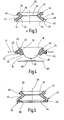
- Fig. 4 shows the final or stop position of the compression unit 24 when pressing the finger 16.
- the wedge-shaped stop bead 40 fills the outside gap between the sections 30, 32 gap-free, so that due to the incompressibility of the elastomer material even with a low coefficient of friction of the skin prevents complete folding becomes.
- the kink 54 is correspondingly in the pressing direction down relocated.
- the engagement part 34 thereby projects into the interior 18 of the housing 12 and in any case under the housing-side boundary surface 50 of the support member 26. Accordingly, a removal region 56 of the finger-berry 16 in the housing interior 18 is exposed. After the puncture, an escaping blood drop 58 can thus be removed freely through a two-dimensional test field 60 without the need for punctiform access.
- This type of automatic blood collection is particularly suitable in combination with a tape cassette system with which a plurality of test fields 60 stored on a carrier tape 62 can be successively transported into the engagement area of the body part 16.
- an abutment 64 is provided here, which is attached to the housing-side boundary surface 50 of the support member 26.
- the abutment 64 protrudes into the region of the opening 44 in order to limit the indentation depth of the compression element 24.
- the abutment 64 is chamfered downwards in the opening region to form a free peripheral edge, so that a stop surface 66, which is bevelled in the opposite direction to the inner surface 52 of the compression element 24, is created for a positive support.
- a stop surface 66 which is bevelled in the opposite direction to the inner surface 52 of the compression element 24, is created for a positive support.
Description
Die Erfindung betrifft eine Vorrichtung und ein Verfahren zur Positionierung eines Körperteils, insbesondere einer Fingerbeere, an einem Analysegerät für Körperflüssigkeiten sowie ein entsprechendes Analysegerät gemäß dem Oberbegriff der unabhängigen Patentansprüche.The invention relates to a device and a method for positioning a body part, in particular a fingertip, on an analysis device for body fluids and a corresponding analyzer according to the preamble of the independent claims.
Aus der
Ausgehend hiervon liegt der Erfindung die Aufgabe zugrunde, die im Stand der Technik aufgetretenen Nachteile zu vermeiden und eine Positioniervorrichtung und ein entsprechendes Verfahren dahingehend zu verbessern, dass eine zuverlässige definierte Positionierung eines Körperteils frei von Störkonturen für eine insbesondere flächige Flüssigkeitsabnahme mit einfachen Mitteln erreicht wird.Based on this, the present invention seeks to avoid the disadvantages of the prior art and to improve a positioning device and a corresponding method to the effect that a reliable defined positioning of a body part free of interfering contours for a particular flat liquid removal is achieved by simple means.
Zur Lösung dieser Aufgabe wird die in den unabhängigen Patentansprüchen angegebene Merkmalskombination vorgeschlagen. Vorteilhafte Ausgestaltungen und Weiterbildungen der Erfindung ergeben sich aus den abhängigen Ansprüchen.To solve this problem, the combination of features specified in the independent claims is proposed. Advantageous embodiments and modifications of the invention will become apparent from the dependent claims.
Die Erfindung geht von dem Gedanken aus, eine möglichst große Eindrücktiefe für das Körperteil in das Geräteinnere hinein sicher zu stellen. Dementsprechend wird erfindungsgemäß vorgeschlagen, dass das Kompressionselement eine in das Gehäuse eindrückbare Eingriffspartie für das Körperteil aufweist, so dass ein Entnahmebereich des Körperteils im Inneren des Gehäuses gegenüber einem flächigen Testfeld zur Flüssigkeitsentnahme exponiert ist. Auf diese Weise kann der Freiraum im Geräteinneren für einen Flüssigkeitsauftrag auf ein flächiges Substrat genutzt werden, ohne dass ein Flüssigkeitstransport beispielsweise über eine Kapillarstruktur erforderlich wäre. Die Entnahme unterhalb von Gehäusekanten erlaubt einen hygienischen Messablauf mit geringen Flüssigkeitsmengen (Blut oder Gewebeflüssigkeit), während die tief liegende Eingriffspartie für eine ortsfeste Positionierung sorgt. Zugleich ist durch die flächige Aufnahme auf dem Testfeld eine hohe Positionstoleranz gegeben.The invention is based on the idea of ensuring the greatest possible penetration depth for the body part into the interior of the device. Accordingly, the invention proposes that the compression element has a depressible into the housing engagement portion for the body part, so that a removal region of the body part is exposed in the interior of the housing relative to a flat test field for liquid removal. In this way, the space inside the device can be used for a liquid application to a flat substrate, without a liquid transport would be required, for example via a capillary structure. The removal below the edges of the housing allows a hygienic measuring process with small amounts of fluid (blood or tissue fluid), while the low-lying engagement part ensures a fixed positioning. At the same time, a high positional tolerance is given by the areal recording on the test field.
Vorteilhafterweise ist die Eingriffspartie zumindest bis zu der Ebene einer gehäuseseitigen Begrenzung des Trägerteils eindrückbar, so dass der überstehende bzw. abgeschnürte Bereich des Körperteils frei zugänglich liegt.Advantageously, the engagement part can be pressed in at least up to the level of a housing-side boundary of the carrier part, so that the protruding or constricted region of the body part is freely accessible.
Für eine weitere Verbesserung der Positioniergenauigkeit sind Anschlagmittel zur Begrenzung der Eindrücktiefe des Kompressionselements vorgesehen.For a further improvement of the positioning accuracy stop means for limiting the Eindrücktiefe the compression element are provided.
Ein besonderer Aspekt der Erfindung liegt darin, dass das im Querschnitt ringförmige Kompressionselement an einer freien Außenkante durch eine nach außen abstehende Anschlagwulst verbreitert ist. Dadurch wird beim Eindrücken eine Anschlagsituation erreicht, in der ein weiteres Durchstülpen des Kompressionselements zuverlässig verhindert wird.A particular aspect of the invention is that the annular compression element is widened at a free outer edge by an outwardly projecting stop bead. This is when Pressing reaches a stop situation in which a further slippage of the compression element is reliably prevented.
Eine vorteilhafte Ausgestaltung sieht vor, dass das Kompressionselement zwei in Richtung der Andrückachse konisch aufeinander zulaufende Teilbereiche aufweist, wobei der distale Teilbereich eine beim Andrücken des Körperteils außenseitig gegen den proximalen Teilbereich anschlagende Anschlagwulst aufweist. Um ein sicheres Abstoppen zu gewährleisten, ist es von Vorteil, wenn die Anschlagwulst sich von der freien Außenkante des Kompressionselements weg vorzugsweise keilförmig verjüngt.An advantageous embodiment provides that the compression element has two partial regions conically converging toward one another in the direction of the pressure axis, wherein the distal partial region has an abutment bead on the outside against the proximal partial region when the body part is pressed against it. In order to ensure a secure stopping, it is advantageous if the stop bead tapers away from the free outer edge of the compression element preferably wedge-shaped.
Alternativ oder ergänzend ist es auch möglich, dass das Trägerteil eine Öffnung zum Eindrücken des Kompressionselements aufweist, und dass gehäuseseitig an dem Trägerteil ein in den Öffnungsbereich ragendes Widerlager zur Begrenzung der Eindrücktiefe des Kompressionselements angebracht ist. Für eine sichere Abstützung ist es günstig, wenn das Widerlager durch einen in die Öffnung des Trägerteils hinein sich verjüngenden Anschlagring gebildet ist.Alternatively or additionally, it is also possible that the support part has an opening for pressing the compression element, and that on the housing side on the support part projecting into the opening portion abutment for limiting the Eindrücktiefe the compression element is attached. For a secure support, it is advantageous if the abutment is formed by a tapered into the opening of the support member stop ring.
Für einen möglichst tief reichenden Eingriff ist es von Vorteil, wenn das Kompressionselement mit einem Öffnungsrand des Trägerteils fest verbunden ist, wobei die Verbindungsfläche sich über die gesamte Höhe des Öffnungsrandes erstreckt, so dass das Einstülpen bei der Kompression möglichst tief im Gehäusebereich erfolgt.For a deepest possible engagement, it is advantageous if the compression element is fixedly connected to an opening edge of the support part, wherein the connecting surface extends over the entire height of the opening edge, so that the invagination occurs as deep as possible in the housing area during compression.
Um die Krafteinleitung zu optimieren, ist es vorteilhaft, wenn die Verbindungsfläche zwischen Trägerteil und Kompressionselement als Schräge von einer gehäuseseitigen Begrenzungsfläche des Trägerteils abgewandt ist, wobei der Winkel, zwischen der Schräge und der Begrenzungsfläche im Bereich von 50° bis 70°, vorzugsweise bei 60° liegen sollte.In order to optimize the introduction of force, it is advantageous if the connection surface between carrier part and compression element is facing away from a housing-side boundary surface of the carrier part as a slope, wherein the angle between the slope and the boundary surface in the range of 50 ° to 70 °, preferably at 60 ° should lie.
Für den Kompressionsvorgang ist es auch vorteilhaft, wenn das Kompressionselement im Ausgangszustand eine auf eine gehäuseseitigen Randkante des Trägerteils knickfrei zulaufende Innenfläche aufweist.For the compression process, it is also advantageous if, in the initial state, the compression element has an inner surface which tapers on a housing-side peripheral edge of the carrier part.
Zur verbesserten Anpassung an eine gewölbte Körperteilkontur und zur sicheren Haftung ist es vorteilhaft, wenn die Eingriffspartie durch die Innenkante einer konkav gewölbten Ringfläche des Kompressionselements gebildet ist.For improved adaptation to a curved body part contour and for secure adhesion, it is advantageous if the engagement part is formed by the inner edge of a concavely curved annular surface of the compression element.
Herstellungstechnisch ist es günstig, wenn das Kompressionselement als Formteil, vorzugsweise als Spritzgussteil an dem vorgefertigten Trägerteil angeformt ist. Dabei kann das Kompressionselement über eine insbesondere durch einen Primer gebildete Klebeverbindung an dem Trägerteil befestigt werden.Manufacturing technology, it is advantageous if the compression element is formed as a molded part, preferably as an injection molded part on the prefabricated support member. In this case, the compression element can be attached to the carrier part via an adhesive bond formed in particular by a primer.
Vorteilhafterweise besteht das Kompressionselement aus Silikon, Gummi oder Polyurethan. Aus hygienischen Gründen wird bevorzugt Silikon eingesetzt.Advantageously, the compression element made of silicone, rubber or polyurethane. For reasons of hygiene, silicone is preferably used.
In baulich vorteilhafter Ausführung ist das Trägerteil als formstabile Ringscheibe insbesondere aus Metall ausgebildet.In structurally advantageous embodiment, the carrier part is designed as a dimensionally stable annular disc, in particular made of metal.
Eine einstufige Herstellung lässt sich dadurch realisieren, dass das aus einem thermoplastischen Elastomer bestehende Kompressionselement und das aus Kunststoff bestehende Trägerteil als Zweikomponenten-Spritzgussteil ausgebildet sind.A one-step production can be realized in that the existing of a thermoplastic elastomer compression element and the plastic carrier part are formed as a two-component injection molded part.
Um einen Austausch beispielsweise zur Anpassung an die Körperteilgröße oder zur Reinigung zu erlauben, ist das Trägerteil lösbar in eine Gehäuseaufnahme einsetzbar.In order to allow an exchange, for example, to adapt to the body part size or for cleaning, the support member is releasably inserted into a housing receptacle.
Für eine kompakte Bauform eines Handgeräts ist es günstig, wenn die Gesamtbreite des Trägerteils senkrecht zur Andrückrichtung weniger als 25 mm, vorzugsweise weniger als 20 mm beträgt.For a compact design of a hand-held device, it is favorable if the total width of the carrier part perpendicular to the pressing direction is less than 25 mm, preferably less than 20 mm.
Ein weiterer Aspekt der Erfindung betrifft ein Analysegerät für Körperflüssigkeiten, insbesondere zur Blutzuckerbestimmung, mit einem Gehäuse und einer Vorrichtung zur Positionierung eines Körperteils, insbesondere einer Fingerbeere, umfassend ein vorzugsweise ringförmiges flexibles Kompressionselement zum Andrücken des Körperteils unter Druckerhöhung und ein starres Trägerteil zur Halterung des Kompressionselements an dem Gehäuse,. Hier wird erfindungsgemäß vorgeschlagen, dass das Kompressionselement eine in das Gehäuse eindrückbare Eingriffspartie für das Körperteil aufweist, so dass ein Entnahmebereich des Körperteils im Inneren des Gehäuses gegenüber einem flächigen Testfeld zur Flüssigkeitsentnahme exponiert ist. Damit können die bereits zuvor beschriebenen Vorteile in einem kompakten Handgerät realisiert werden.Another aspect of the invention relates to an analysis device for body fluids, in particular for blood sugar determination, comprising a housing and a device for positioning a body part, in particular a finger berry, comprising a preferably annular flexible compression element for pressing the body part under pressure increase and a rigid support member for holding the compression element on the housing ,. Here, the invention proposes that the compression element has a compressible into the housing engagement portion for the body part, so that a removal region of the body part is exposed in the interior of the housing against a flat test field for liquid removal. Thus, the advantages already described above can be realized in a compact handset.
Zur Magazinierung ist bevorzugt ein Testband im Gehäuseinneren angeordnet sein, welches auf einem aufwickelbaren Trägerband eine Vielzahl von Testfeldern aufweist. Weiterhin sind für ein integriertes System im Gehäuseinneren eine Stecheinrichtung zum Einstechen in den Entnahmebereich des Körperteils sowie eine Analyseeinrichtung zum Nachweis eines Analyten auf einem mit Körperflüssigkeit beaufschlagten Testfeld angeordnet.For storage, a test tape is preferably disposed inside the housing, which has a plurality of test fields on a windable carrier tape. Furthermore, a piercing device for piercing into the removal region of the body part as well as an analysis device for detecting an analyte are arranged on a test field loaded with body fluid for an integrated system inside the housing.
Vorteilhafterweise sind die aufeinanderfolgend auf dem vorzugsweise in einer Kassette befindlichen Testband angeordneten Testfelder durch eine Bandtransportvorrichtung sukzessive in eine aktive Position bezüglich des Entnahmebereichs des Körperteils, der Stecheinrichtung und/oder der Analyseeinrichtung bewegbar.Advantageously, the test fields arranged successively on the test tape, which is preferably located in a cassette, are successively movable by a tape transport device into an active position with respect to the removal area of the body part, the lancing device and / or the analysis device.
Eine weitere Vereinfachung wird dadurch erreicht, dass die Stechvorrichtung eine distale Andrückfläche zum Andrücken eines Testfelds gegen den Entnahmebereich des Körperteils aufweist.A further simplification is achieved in that the lancing device has a distal pressing surface for pressing a test field against the removal region of the body part.
Um die Flüssigkeitsaufnahme gerade auch bei kleinen Mengen möglichst positionstolerant zu gestalten, ist es von besonderem Vorteil, wenn die mit Körperflüssigkeit beaufschlagbare Aufnahmefläche des Testfelds mehr als 2x5 mm2, vorzugsweise etwa 5 x 20 mm2 beträgt.In order to make the liquid intake as positionally tolerant as possible, especially with small quantities, it is particularly advantageous if the receiving surface of the test field which can be acted upon by body fluid is more than 2 × 5 mm 2 , preferably approximately 5 × 20 mm 2 .
In verfahrensmäßiger Hinsicht wird die eingangs genannte Aufgabe dadurch gelöst, dass das Körperteil beim Andrücken in das Gehäuse hinein eindringt, wobei ein Entnahmebereich des Körperteils im Inneren des Gehäuses gegenüber einem flächigen Testfeld für eine Flüssigkeitsentnahme freigehalten wird.In procedural terms, the object mentioned in the introduction is achieved in that the body part penetrates into the housing when it is pressed, wherein a removal region of the body part in the interior of the housing is kept free from a flat test field for a liquid removal.
Um die Benutzerfreundlichkeit weiter zu verbessern, ist es vorteilhaft, wenn im Gehäuseinneren auf einem Testband magazinierte Testfelder mit Körperflüssigkeit an dem exponierten Entnahmebereich des Körperteils beaufschlagt werden.In order to further improve the user-friendliness, it is advantageous if test fields loaded with body fluid are applied to the exposed removal region of the body part on a test tape inside the housing.
Zur Integration der einzelnen Analyseschritte wird im Gehäuseinneren eine Stecheinrichtung in den Entnahmebereich eingestochen, wobei unter dem erhöhten Innendruck aufgestaute Körperflüssigkeit aus der erzeugten Stichwunde austritt. Hierbei ist es günstig, wenn während einer Phase des Flüssigkeitsaustritts die Stecheinrichtung und das Testband von dem Entnahmebereich des Körperteils entfernt sind.In order to integrate the individual analysis steps, a lancing device is inserted into the removal area inside the housing, wherein body fluid accumulated under the increased internal pressure escapes from the puncture wound produced. In this case, it is favorable if, during a phase of the liquid outlet, the lancing device and the test strip are removed from the removal region of the body part.
Vorteilhafterweise wird das vorzugsweise in einer Kassette aufgewickelte Testband vorgespult, so dass ein unverbrauchtes Testfeld in eine aktive Position bezüglich des Entnahmebereichs des Körperteils gelangt.Advantageously, the preferably wound in a cassette test tape is pre-wound, so that an unconsumed test field comes into an active position with respect to the removal region of the body part.
Eine weitere verfahrensmäßige Vereinfachung wird dadurch erreicht, dass ein Testfeld durch Querauslenkung des Testbands mit aus dem Entnahmebereich des Körperteils ausgetretener Körperflüssigkeit beaufschlagt wird.A further procedural simplification is achieved in that a test field is acted upon by transverse deflection of the test band with body fluid escaping from the removal region of the body part.
Bevorzugt wird die Eindrücktiefe des Kompressionselements durch Anschlagmittel begrenzt.Preferably, the indentation depth of the compression element is limited by stop means.
Besonders günstig ist es auch, wenn das Kompressionselement über ein starres Trägerteil als Austauschteil an dem Gehäuse entnehmbar gehalten wird.It is also particularly favorable if the compression element is held removably on the housing via a rigid carrier part as a replacement part.
Im Folgenden wird die Erfindung anhand der in der Zeichnung schematisch dargestellten Ausführungsbeispiele näher erläutert. Es zeigen:
- Fig. 1
- ein tragbares Analysegerät zur Blutzuckerbestimmung mit einer Vorrichtung zur Fingerpositionierung in perspektivischer Darstellung;
- Fig. 2 und 3
- die aus dem Gerät entnehmbare Positioniervorrichtung in perspektivischer Darstellung und im Axialschnitt;
- Fig. 4
- die Positioniervorrichtung mit angedrücktem Finger zur Beaufschlagung eines Testelements im Axialschnitt;
- Fig. 5
- eine weitere Ausführungsform in einer
Fig. 3 entsprechenden Darstellung; und - Fig. 6a bis e
- den Ablauf einer Blutentnahme/Analyse jeweils im Axialschnitt.
- Fig. 1
- a portable analyzer for blood sugar determination with a device for finger positioning in perspective view;
- FIGS. 2 and 3
- the removable from the device positioning device in a perspective view and in axial section;
- Fig. 4
- the positioning device with pressed finger for applying a test element in axial section;
- Fig. 5
- another embodiment in one
Fig. 3 corresponding representation; and - Fig. 6a to e
- the sequence of a blood collection / analysis in each case in axial section.
Die in der Zeichnung dargestellte Positioniervorrichtung 10 ist als leicht austauschbares Einsatzteil in das Gehäuse 12 eines tragbaren Blutzuckermessgeräts 14 einsetzbar, um eine Fingerbeere 16 eines Probanden im Geräteinneren 18 zur Blutentnahme und -analyse zu positionieren.The
Zu diesem Zweck weist das in
Wie am besten aus
Zur besseren Anpassung an die Fingerkontur weist der obere bzw. distale Teilbereich 30 eine konkav gewölbte innere Ringfläche 38 auf. Dadurch ergibt sich beim Andrücken des Fingers 16 zunächst ein kreisförmiger Kantenkontakt im Bereich der Eingriffspartie 34 mit hoher Flächenpressung für eine rutschsichere Positionierung.For better adaptation to the finger contour, the upper or
Um die Andrückbewegung zuverlässig zu stoppen, ist an der freien Außenkante des distalen Teilbereichs 30 eine Anschlagwulst 40 angeformt, die sich zu dem proximalen Teilbereich 32 hin keilförmig verjüngt. Die Anschlagwulst 40 stützt sich in der Anschlagstellung an der Außenseite 42 des Teilbereichs 32 ab und verhindert somit ein weiteres Umklappen des Kompressionselements 24 in Andrückrichtung.In order to stop the pressing movement reliably, a
Das Trägerteil 26 begrenzt als Ringscheibe eine Durchtrittsöffnung 44 für das Kompressionselement 24. An seinem Öffnungsrand 46 ist das Trägerteil 26 über seine gesamte Höhe bzw. Wandstärke mittels Klebeverbindung fest mit dem Kompressionselement 24 verbunden. Für eine günstige Krafteinleitung ist die Verbindungsfläche 48 als Schräge unter einem spitzen Winkel von etwa 60° gegenüber der gehäuseseitigen Begrenzungsfläche 50 des Trägerteils angeordnet. Um eine große Eindrücktiefe zu erreichen, läuft die Innenfläche 52 des proximalen Teilbereichs 32 mit glatter Kontur knickfrei auf die gehäuseseitige Randkante des Öffnungsrandes 46 zu.The
Die Kompressionseinheit 24 ist als flexibles Formteil aus Silikon gebildet, während das Trägerteil 26 aus Metall, vorzugsweise Aluminium besteht. Das Kompressionselement kann dabei im Spritzgussverfahren an das in ein Spritzgusswerkzeug eingelegte Trägerteil angeformt werden, wobei ein Primer an der Verbindungsfläche 48 die Festigkeit der Klebeverbindung erhöht. Alternativ ist auch eine Herstellung im Zweikomponenten-Spritzgussverfahren denkbar, wobei die Kompressionseinheit 24 aus einem thermoplastischen Elastomer und das Trägerteil 26 aus Kunststoff in einem Arbeitsgang als Verbundteil geformt werden.The
Durch die tiefe Anbindung des proximalen Teilbereichs 32 an dem Öffnungsrand 46 wird die Knickstelle 54 entsprechend in Andrückrichtung nach unten verlagert. Die Eingriffspartie 34 ragt dadurch bis in das Innere 18 des Gehäuses 12 und jedenfalls unter die gehäuseseitige Begrenzungsfläche 50 des Trägerteils 26. Entsprechend wird ein Entnahmebereich 56 der Fingerbeere 16 im Gehäuseinneren 18 exponiert. Nach dem Einstich kann somit ein austretender Blutstropfen 58 frei durch ein flächiges Testfeld 60 abgenommen werden, ohne dass ein punktförmiger Zugriff erforderlich wäre. Diese Art der automatischen Blutgewinnung eignet sich besonders in Kombination mit einem Bandkassettensystem, mit dem eine Vielzahl von auf einem Trägerband 62 magazinierten Testfeldern 60 sukzessive in den Eingriffsbereich des Körperteils 16 transportiert werden können.Due to the deep connection of the
Bei der in
In
Durch das Andrücken der Fingerkuppe 16 gegen das Kompressionselement 24 werden die Blutkapillaren in dem eingepressten Fingerbereich 76 abgeschnürt, während der Entnahmebereich 56 im Geräteinneren 18 für die Blutentnahme freigehalten wird (
Gemäß
Wie in
Claims (31)
- Analytical instrument for body fluids, in particular for determining blood sugar, comprising a housing (12) and a device for positioning a body part (16), in particular a finger pad, comprising a preferably circular flexible compression element (24) for pressing against the body part (16) while increasing the pressure and a rigid support part (26) to hold the compression element (24) on the housing (12), wherein an analytical device (13) for detecting an analyte on a test field (60) to which body fluid has been applied is arranged in the interior of the housing (18) and the compression element (24) has an engaging member (34) for the body part (16) which is pressed into the housing (12) during liquid withdrawal such that a withdrawal region (56) of the body part (16) is exposed in the interior (18) of the housing (12) opposite to a flat test field (60), wherein the compression element (24) has two subregions (30, 32) which converge in a conical manner to each other in direction of a pressure axis (28), characterized in that the distal subregion (30) has a stop bead (40) which abuts against the outside of the proximal subregion (30) in order to limit the impression depth when the body part (16) is pressed on.
- Analytical instrument according to claim 1, characterized in that the engaging member (34) can be pressed in at least up to the plane of a boundary (50) of the support part (26) on the side of the housing.
- Analytical instrument according to claim 1 or 2, characterized in that the compression element (24) with a circular cross-section has a free outer edge that is widened by an outwardly projecting stop bead (40).
- Analytical instrument according to one of the claims 1 to 3, characterized in that the stop bead (40) tapers preferably in a wedge-like manner away from the free outer edge of the compression element (24).
- Analytical instrument according to one of the claims 1 to 4, characterized in that the support part (26) has an opening (44) to press in the compression element (24) and that an abutment (64) extending into the area of the opening region is attached to the housing side of the support part (26) in order to limit the depth of impression of the compression element (24).
- Analytical instrument according to claim 5, characterized in that the abutment (64) is formed by a stop ring which tapers into the opening (44) of the support part (26).
- Analytical instrument according to one of the claims 1 to 6, characterized in that the compression element (24) is permanently connected to a rim of the opening (46) in the support part (26) wherein the connecting area (48) extends over the entire height of the rim of the opening (46).
- Analytical instrument according to one of the claims 1 to 7, characterized in that the area (48) connecting the support part (26) and compression element (24) is inclined away from a boundary surface (50) of the support part (26) on the housing where the angle between the incline and the boundary surface is in the range of 50° to 70°, preferably 60°.
- Analytical instrument according to one of the claims 1 to 8, characterized in that the compression element (24) in the initial position has an inner surface (52) which tapers in a kink-free manner towards a lateral edge of the support part (26) on side of the housing.
- Analytical instrument according to one of the claims 1 to 9, characterized in that the engaging member (34) is formed by the inner edge of a concavely curved ring surface (38) of the compression element (24).
- Analytical instrument according to one of the claims 1 to 10, characterized in that the compression element (24) is moulded as a moulded part, preferably as an injection moulded part onto the prefabricated support part (26).
- Analytical instrument according to one of the claims 1 to 11, characterized in that the compression element (24) consisting of a thermoplastic elastomer and the support part (26) consisting of plastic are formed as a two component injection moulded part.
- Analytical instrument according to one of the claims 1 to 12, characterized in that the compression element (24) can be attached to the support part (26) by an adhesive bond and in particular by an adhesive bond formed by a primer.
- Analytical instrument according to one of the claims 1 to 13, characterized in that the compression element (24) is composed of silicon, rubber or polyurethane.
- Analytical instrument according to one of the claims 1 to 14, characterized in that the support part (26) is constructed as a dimensionally stable ring washer and especially one made of metal.
- Analytical instrument according to one of the claims 1 to 15, characterized in that the support part (26) can be inserted into a housing receiving member (20) in a detachable manner.
- Analytical instrument according to one of the claims 1 to 16, characterized in that the total width of the support part (26) perpendicular to the pressing direction (28) is less than 25 mm, preferably less than 20 mm.
- Analytical instrument according to one of the claims 1 to 17, characterized in that a test tape is arranged in the interior of the housing (18) which has a plurality of test fields (60) on a windable support tape (62).
- Analytical instrument according to one of the claims 1 to 18, characterized in that a lancing device (11) for insertion into the withdrawal region (56) of the body part (16) is arranged in the interior of the housing (18).
- Analytical instrument according to one of the claims 1 to 19, characterized in that an analytical device (13) for detecting an analyte on a test field (60) to which body fluid has been applied is arranged in the interior of the housing (18).
- Analytical instrument according to one of the claims 1 to 20, characterized in that the test fields (60) arranged consecutively on the test tape that is preferably located in a cassette can be moved successively into an active position with regard to the withdrawal region (56) of the body part (16), and/or the lancing device (11) and/or the analytical device (13) by means of a tape transport device.
- Analytical instrument according to one of the claims 1 to 21, characterized in that the lancing device (11) has a distal pressing face to press a test field (60) against the withdrawal region (56) of the body part (16).
- Analytical instrument according to one of the claims 1 to 22, characterized in that the receiving area of the test field (60) to which body fluid can be applied is more than 2 x 5 mm2 and preferably 5 x 20 mm2.
- Method for analysing body fluids, in particular for determining blood sugar, in which a body part (16), in particular a finger pad, is positioned on an analyser (14), wherein the body part is pressed against a circular flexible compression element (24) in order to increase the internal pressure, wherein an analytical device (13) for detecting an analyte on a test field (60) to which body fluid has been applied is arranged in the interior of the housing (18) and wherein the compression element (24) has an engaging member (34) for the body part (16) which can be pressed into the housing (12) and the body part (16) penetrates into the housing (12) when it is pressed down, such that a withdrawal region (56) of the body part (16) is kept clear in the interior (18) of the housing (12) opposite to the flat test field (60) in order to remove liquid, wherein the compression element (24) has two subregions (30, 32) which converge in a conical manner towards each other, wherein the distal subregion (30) has a stop bead (40), and wherein the impression depth is limited by means of the stop bead (40) which abuts against the outside the proximal subregion (30) when the body part (16) is pressed on.
- Method according to claim 24, characterized in that body fluid on the exposed withdrawal region (56) of the body part (16) is applied to test fields (60) stored on a test tape in the interior of the housing (18).
- Method according to claim 24 or 25, characterized in that a lancing device (11) is inserted into the withdrawal region (56) in the interior of the housing (18) whereby body fluid dammed up under the increased inner pressure emerges from the generated puncture wound.
- Method according to one of the claims 24 to 26, characterized in that the lancing device (11) and the test tape are removed from the withdrawal region (56) of the body part (16) during a phase of liquid efflux.
- Method according to one of the claims 24 to 27, characterized in that a test tape preferably wound up in a cassette is advantageously wound on such that an unused test field (60) is moved to an active position relative to the withdrawal region (56) of the body part (16).
- Method according to one of the claims 24 to 28, characterized in that a body fluid that has escaped from the withdrawal region (56) of the body part (16) is applied to a test field (60) by a lateral excursion of the test tape.
- Method according to one of the claims 24 to 29, characterized in that the compression element (24) is held on the housing (12) as a replaceable part in a removable manner by means of a rigid support part (26).
- Method according to one of the claims 24 to 30 characterized in that the engaging member (34) can be pressed in at least up to the plane of a boundary (50) of the support part (26) on the side of the housing.
Applications Claiming Priority (2)
| Application Number | Priority Date | Filing Date | Title |
|---|---|---|---|
| DE102004024970A DE102004024970A1 (en) | 2004-05-21 | 2004-05-21 | Device and method for positioning a body part |
| PCT/EP2005/005301 WO2005112763A1 (en) | 2004-05-21 | 2005-05-14 | Device and method for positioning a body part |
Publications (2)
| Publication Number | Publication Date |
|---|---|
| EP1746938A1 EP1746938A1 (en) | 2007-01-31 |
| EP1746938B1 true EP1746938B1 (en) | 2015-03-25 |
Family
ID=34972601
Family Applications (1)
| Application Number | Title | Priority Date | Filing Date |
|---|---|---|---|
| EP05761585.8A Not-in-force EP1746938B1 (en) | 2004-05-21 | 2005-05-14 | Device and method for positioning a body part |
Country Status (8)
| Country | Link |
|---|---|
| US (2) | US8376959B2 (en) |
| EP (1) | EP1746938B1 (en) |
| JP (1) | JP4825201B2 (en) |
| CN (1) | CN101001571B (en) |
| CA (1) | CA2567204C (en) |
| DE (1) | DE102004024970A1 (en) |
| HK (1) | HK1109722A1 (en) |
| WO (1) | WO2005112763A1 (en) |
Families Citing this family (18)
| Publication number | Priority date | Publication date | Assignee | Title |
|---|---|---|---|---|
| US7004928B2 (en) | 2002-02-08 | 2006-02-28 | Rosedale Medical, Inc. | Autonomous, ambulatory analyte monitor or drug delivery device |
| US7052652B2 (en) | 2003-03-24 | 2006-05-30 | Rosedale Medical, Inc. | Analyte concentration detection devices and methods |
| DE102004024970A1 (en) * | 2004-05-21 | 2005-12-08 | Roche Diagnostics Gmbh | Device and method for positioning a body part |
| US20060281187A1 (en) | 2005-06-13 | 2006-12-14 | Rosedale Medical, Inc. | Analyte detection devices and methods with hematocrit/volume correction and feedback control |
| US8801631B2 (en) | 2005-09-30 | 2014-08-12 | Intuity Medical, Inc. | Devices and methods for facilitating fluid transport |
| CA2624059C (en) | 2005-09-30 | 2019-04-02 | Intuity Medical, Inc. | Multi-site body fluid sampling and analysis cartridge |
| ATE513511T1 (en) | 2005-10-08 | 2011-07-15 | Hoffmann La Roche | STICKING SYSTEM |
| ATE525647T1 (en) * | 2006-06-27 | 2011-10-15 | Hoffmann La Roche | DIAGNOSTIC TAPE CASSETTE |
| US20080065130A1 (en) * | 2006-08-22 | 2008-03-13 | Paul Patel | Elastomeric toroidal ring for blood expression |
| WO2009145920A1 (en) | 2008-05-30 | 2009-12-03 | Intuity Medical, Inc. | Body fluid sampling device -- sampling site interface |
| CA2726067C (en) | 2008-06-06 | 2020-10-20 | Intuity Medical, Inc. | Detection meter and mode of operation |
| US10383556B2 (en) | 2008-06-06 | 2019-08-20 | Intuity Medical, Inc. | Medical diagnostic devices and methods |
| EP2506768B1 (en) | 2009-11-30 | 2016-07-06 | Intuity Medical, Inc. | Calibration material delivery devices and methods |
| EP2584964B1 (en) | 2010-06-25 | 2021-08-04 | Intuity Medical, Inc. | Analyte monitoring devices |
| EP4339613A2 (en) | 2011-08-03 | 2024-03-20 | Intuity Medical, Inc. | Body fluid sampling arrangement |
| US10729386B2 (en) | 2013-06-21 | 2020-08-04 | Intuity Medical, Inc. | Analyte monitoring system with audible feedback |
| EP3503806B1 (en) | 2016-08-24 | 2020-09-30 | Becton, Dickinson and Company | A device for obtaining a blood sample |
| CN110891485A (en) * | 2017-08-02 | 2020-03-17 | 豪夫迈·罗氏有限公司 | Glucose testing device and method |
Citations (1)
| Publication number | Priority date | Publication date | Assignee | Title |
|---|---|---|---|---|
| US6093156A (en) * | 1996-12-06 | 2000-07-25 | Abbott Laboratories | Method and apparatus for obtaining blood for diagnostic tests |
Family Cites Families (15)
| Publication number | Priority date | Publication date | Assignee | Title |
|---|---|---|---|---|
| US4781680A (en) * | 1987-03-02 | 1988-11-01 | Vir Engineering | Resealable injection site |
| US5951493A (en) * | 1997-05-16 | 1999-09-14 | Mercury Diagnostics, Inc. | Methods and apparatus for expressing body fluid from an incision |
| US5962826A (en) * | 1997-07-03 | 1999-10-05 | Bassin; Gilbert | Bellows switch actuator |
| US6121559A (en) * | 1997-07-03 | 2000-09-19 | Bassin; Gilbert | Bellows |
| US5964718A (en) | 1997-11-21 | 1999-10-12 | Mercury Diagnostics, Inc. | Body fluid sampling device |
| US6197040B1 (en) * | 1999-02-23 | 2001-03-06 | Lifescan, Inc. | Lancing device having a releasable connector |
| JP4210782B2 (en) * | 1999-10-13 | 2009-01-21 | アークレイ株式会社 | Blood sampling position indicator |
| DE19955652A1 (en) * | 1999-11-19 | 2001-06-13 | Schott Glas | Closure for a prefillable disposable syringe |
| DE10026170A1 (en) * | 2000-05-26 | 2001-12-06 | Roche Diagnostics Gmbh | Body fluid withdrawal system |
| DE10026172A1 (en) | 2000-05-26 | 2001-11-29 | Roche Diagnostics Gmbh | Body fluid withdrawal system |
| ES2315961T3 (en) * | 2001-06-08 | 2009-04-01 | F. Hoffmann-La Roche Ag | BODY FLUID SAMPLE EXTRACTION DEVICE. |
| ATE343349T1 (en) * | 2001-06-08 | 2006-11-15 | Hoffmann La Roche | DEVICES FOR EXPRESSING BODY FLUID FROM AN INCISION |
| US20060184189A1 (en) * | 2002-11-15 | 2006-08-17 | Lorin Olson | Cap for a dermal tissue lancing device |
| DE10332488A1 (en) * | 2003-07-16 | 2005-02-24 | Roche Diagnostics Gmbh | Analyzer and analysis method for body fluids |
| DE102004024970A1 (en) * | 2004-05-21 | 2005-12-08 | Roche Diagnostics Gmbh | Device and method for positioning a body part |
-
2004
- 2004-05-21 DE DE102004024970A patent/DE102004024970A1/en not_active Ceased
-
2005
- 2005-05-14 WO PCT/EP2005/005301 patent/WO2005112763A1/en active Application Filing
- 2005-05-14 EP EP05761585.8A patent/EP1746938B1/en not_active Not-in-force
- 2005-05-14 CN CN2005800163347A patent/CN101001571B/en not_active Expired - Fee Related
- 2005-05-14 JP JP2007517060A patent/JP4825201B2/en not_active Expired - Fee Related
- 2005-05-14 CA CA2567204A patent/CA2567204C/en not_active Expired - Fee Related
-
2006
- 2006-11-21 US US11/562,242 patent/US8376959B2/en active Active
-
2008
- 2008-01-15 HK HK08100500.5A patent/HK1109722A1/en not_active IP Right Cessation
-
2013
- 2013-01-17 US US13/743,398 patent/US9226704B2/en not_active Expired - Fee Related
Patent Citations (1)
| Publication number | Priority date | Publication date | Assignee | Title |
|---|---|---|---|---|
| US6093156A (en) * | 1996-12-06 | 2000-07-25 | Abbott Laboratories | Method and apparatus for obtaining blood for diagnostic tests |
Also Published As
| Publication number | Publication date |
|---|---|
| US8376959B2 (en) | 2013-02-19 |
| CA2567204A1 (en) | 2005-12-01 |
| CN101001571A (en) | 2007-07-18 |
| CA2567204C (en) | 2012-04-17 |
| EP1746938A1 (en) | 2007-01-31 |
| JP4825201B2 (en) | 2011-11-30 |
| JP2007537804A (en) | 2007-12-27 |
| US9226704B2 (en) | 2016-01-05 |
| WO2005112763A1 (en) | 2005-12-01 |
| DE102004024970A1 (en) | 2005-12-08 |
| US20130197335A1 (en) | 2013-08-01 |
| US20070100365A1 (en) | 2007-05-03 |
| HK1109722A1 (en) | 2008-06-20 |
| CN101001571B (en) | 2011-11-09 |
Similar Documents
| Publication | Publication Date | Title |
|---|---|---|
| EP1746938B1 (en) | Device and method for positioning a body part | |
| DE60011973T2 (en) | Position indicator for blood sampling | |
| DE10394274B4 (en) | Puncturing device | |
| DE60214788T2 (en) | Split pressure ring for lancet and blood sampling device | |
| EP1289422B1 (en) | System for removing body fluid | |
| DE60116281T2 (en) | METHOD AND DEVICE FOR SAMPLING AND ANALYSIS OF INTERSTITICAL LIQUID AND WHOLE BLOOD | |
| DE60317197T2 (en) | PRECISE GUIDED LANZETTE | |
| DE69827465T2 (en) | DEVICE FOR REMOVING FROM THE INSIDE AND / OR INJECTION IN THE INSIDE OF A CORRUPTED SAMPLING VESSEL | |
| DE602004000825T2 (en) | Integrated lancet and test strips for analytical measurement | |
| EP2395921B1 (en) | Device for verifying analytes in bodily fluids | |
| WO2006100265A1 (en) | Analytical aid with a lancet and a testing element | |
| EP1785090A1 (en) | Lancet device and system for skin detection | |
| WO2008110287A2 (en) | Analytical system for determining an analyte in a body fluid and disposable integrated sample collection and analytical element | |
| EP1491143A1 (en) | Diagnostic or analytic device for single use with integrated lancet | |
| EP2173240B1 (en) | Disposable diagnostic article | |
| WO2001047636A2 (en) | Closure device for a vacuum sample collector | |
| EP2408370B1 (en) | Test device in particular for blood sugar tests | |
| DE69914841T2 (en) | Method and device for taking samples from a test tube | |
| DE4433198C1 (en) | Applicator | |
| DE202021100615U1 (en) | Device for sample collection and testing | |
| DE202016106328U1 (en) | Lid opening structure and physiological detection device | |
| DE202008017883U1 (en) | Device and arrangement for a test strip holder | |
| EP2263796B1 (en) | Container with reference solution | |
| EP1943948A1 (en) | Puncture instrument | |
| DE7915283U1 (en) |
Legal Events
| Date | Code | Title | Description |
|---|---|---|---|
| PUAI | Public reference made under article 153(3) epc to a published international application that has entered the european phase |
Free format text: ORIGINAL CODE: 0009012 |
|
| 17P | Request for examination filed |
Effective date: 20061214 |
|
| AK | Designated contracting states |
Kind code of ref document: A1 Designated state(s): AT BE BG CH CY CZ DE DK EE ES FI FR GB GR HU IE IS IT LI LT LU MC NL PL PT RO SE SI SK TR |
|
| DAX | Request for extension of the european patent (deleted) | ||
| 17Q | First examination report despatched |
Effective date: 20121005 |
|
| GRAP | Despatch of communication of intention to grant a patent |
Free format text: ORIGINAL CODE: EPIDOSNIGR1 |
|
| INTG | Intention to grant announced |
Effective date: 20140922 |
|
| GRAS | Grant fee paid |
Free format text: ORIGINAL CODE: EPIDOSNIGR3 |
|
| GRAA | (expected) grant |
Free format text: ORIGINAL CODE: 0009210 |
|
| RAP1 | Party data changed (applicant data changed or rights of an application transferred) |
Owner name: ROCHE DIAGNOSTICS GMBH Owner name: F.HOFFMANN-LA ROCHE AG |
|
| AK | Designated contracting states |
Kind code of ref document: B1 Designated state(s): AT BE BG CH CY CZ DE DK EE ES FI FR GB GR HU IE IS IT LI LT LU MC NL PL PT RO SE SI SK TR |
|
| REG | Reference to a national code |
Ref country code: GB Ref legal event code: FG4D Free format text: NOT ENGLISH Ref country code: DE Ref legal event code: R081 Ref document number: 502005014732 Country of ref document: DE Owner name: ROCHE DIABETES CARE GMBH, DE Free format text: FORMER OWNERS: ROCHE DIAGNOSTICS GMBH, 68305 MANNHEIM, DE; F. HOFFMANN-LA ROCHE AG, 4070 BASEL, CH |
|
| REG | Reference to a national code |
Ref country code: CH Ref legal event code: EP |
|
| REG | Reference to a national code |
Ref country code: IE Ref legal event code: FG4D Free format text: LANGUAGE OF EP DOCUMENT: GERMAN |
|
| REG | Reference to a national code |
Ref country code: DE Ref legal event code: R096 Ref document number: 502005014732 Country of ref document: DE Effective date: 20150430 |
|
| REG | Reference to a national code |
Ref country code: AT Ref legal event code: REF Ref document number: 717355 Country of ref document: AT Kind code of ref document: T Effective date: 20150515 |
|
| PG25 | Lapsed in a contracting state [announced via postgrant information from national office to epo] |
Ref country code: SE Free format text: LAPSE BECAUSE OF FAILURE TO SUBMIT A TRANSLATION OF THE DESCRIPTION OR TO PAY THE FEE WITHIN THE PRESCRIBED TIME-LIMIT Effective date: 20150325 Ref country code: LT Free format text: LAPSE BECAUSE OF FAILURE TO SUBMIT A TRANSLATION OF THE DESCRIPTION OR TO PAY THE FEE WITHIN THE PRESCRIBED TIME-LIMIT Effective date: 20150325 Ref country code: FI Free format text: LAPSE BECAUSE OF FAILURE TO SUBMIT A TRANSLATION OF THE DESCRIPTION OR TO PAY THE FEE WITHIN THE PRESCRIBED TIME-LIMIT Effective date: 20150325 |
|
| REG | Reference to a national code |
Ref country code: LT Ref legal event code: MG4D |
|
| PG25 | Lapsed in a contracting state [announced via postgrant information from national office to epo] |
Ref country code: GR Free format text: LAPSE BECAUSE OF FAILURE TO SUBMIT A TRANSLATION OF THE DESCRIPTION OR TO PAY THE FEE WITHIN THE PRESCRIBED TIME-LIMIT Effective date: 20150626 |
|
| PG25 | Lapsed in a contracting state [announced via postgrant information from national office to epo] |
Ref country code: NL Free format text: LAPSE BECAUSE OF FAILURE TO SUBMIT A TRANSLATION OF THE DESCRIPTION OR TO PAY THE FEE WITHIN THE PRESCRIBED TIME-LIMIT Effective date: 20150325 |
|
| PG25 | Lapsed in a contracting state [announced via postgrant information from national office to epo] |
Ref country code: RO Free format text: LAPSE BECAUSE OF FAILURE TO SUBMIT A TRANSLATION OF THE DESCRIPTION OR TO PAY THE FEE WITHIN THE PRESCRIBED TIME-LIMIT Effective date: 20150325 Ref country code: SK Free format text: LAPSE BECAUSE OF FAILURE TO SUBMIT A TRANSLATION OF THE DESCRIPTION OR TO PAY THE FEE WITHIN THE PRESCRIBED TIME-LIMIT Effective date: 20150325 Ref country code: CZ Free format text: LAPSE BECAUSE OF FAILURE TO SUBMIT A TRANSLATION OF THE DESCRIPTION OR TO PAY THE FEE WITHIN THE PRESCRIBED TIME-LIMIT Effective date: 20150325 Ref country code: PT Free format text: LAPSE BECAUSE OF FAILURE TO SUBMIT A TRANSLATION OF THE DESCRIPTION OR TO PAY THE FEE WITHIN THE PRESCRIBED TIME-LIMIT Effective date: 20150727 Ref country code: ES Free format text: LAPSE BECAUSE OF FAILURE TO SUBMIT A TRANSLATION OF THE DESCRIPTION OR TO PAY THE FEE WITHIN THE PRESCRIBED TIME-LIMIT Effective date: 20150325 Ref country code: EE Free format text: LAPSE BECAUSE OF FAILURE TO SUBMIT A TRANSLATION OF THE DESCRIPTION OR TO PAY THE FEE WITHIN THE PRESCRIBED TIME-LIMIT Effective date: 20150325 |
|
| PG25 | Lapsed in a contracting state [announced via postgrant information from national office to epo] |
Ref country code: IS Free format text: LAPSE BECAUSE OF FAILURE TO SUBMIT A TRANSLATION OF THE DESCRIPTION OR TO PAY THE FEE WITHIN THE PRESCRIBED TIME-LIMIT Effective date: 20150725 Ref country code: PL Free format text: LAPSE BECAUSE OF FAILURE TO SUBMIT A TRANSLATION OF THE DESCRIPTION OR TO PAY THE FEE WITHIN THE PRESCRIBED TIME-LIMIT Effective date: 20150325 |
|
| REG | Reference to a national code |
Ref country code: CH Ref legal event code: PL |
|
| REG | Reference to a national code |
Ref country code: DE Ref legal event code: R097 Ref document number: 502005014732 Country of ref document: DE |
|
| PG25 | Lapsed in a contracting state [announced via postgrant information from national office to epo] |
Ref country code: CH Free format text: LAPSE BECAUSE OF NON-PAYMENT OF DUE FEES Effective date: 20150531 Ref country code: MC Free format text: LAPSE BECAUSE OF FAILURE TO SUBMIT A TRANSLATION OF THE DESCRIPTION OR TO PAY THE FEE WITHIN THE PRESCRIBED TIME-LIMIT Effective date: 20150325 Ref country code: LI Free format text: LAPSE BECAUSE OF NON-PAYMENT OF DUE FEES Effective date: 20150531 Ref country code: IT Free format text: LAPSE BECAUSE OF FAILURE TO SUBMIT A TRANSLATION OF THE DESCRIPTION OR TO PAY THE FEE WITHIN THE PRESCRIBED TIME-LIMIT Effective date: 20150325 Ref country code: DK Free format text: LAPSE BECAUSE OF FAILURE TO SUBMIT A TRANSLATION OF THE DESCRIPTION OR TO PAY THE FEE WITHIN THE PRESCRIBED TIME-LIMIT Effective date: 20150325 Ref country code: LU Free format text: LAPSE BECAUSE OF FAILURE TO SUBMIT A TRANSLATION OF THE DESCRIPTION OR TO PAY THE FEE WITHIN THE PRESCRIBED TIME-LIMIT Effective date: 20150514 |
|
| PLBE | No opposition filed within time limit |
Free format text: ORIGINAL CODE: 0009261 |
|
| STAA | Information on the status of an ep patent application or granted ep patent |
Free format text: STATUS: NO OPPOSITION FILED WITHIN TIME LIMIT |
|
| GBPC | Gb: european patent ceased through non-payment of renewal fee |
Effective date: 20150625 |
|
| REG | Reference to a national code |
Ref country code: IE Ref legal event code: MM4A |
|
| REG | Reference to a national code |
Ref country code: FR Ref legal event code: ST Effective date: 20160129 |
|
| 26N | No opposition filed |
Effective date: 20160105 |
|
| REG | Reference to a national code |
Ref country code: DE Ref legal event code: R082 Ref document number: 502005014732 Country of ref document: DE Representative=s name: PFIZ/GAUSS PATENTANWAELTE PARTMBB, DE Ref country code: DE Ref legal event code: R082 Ref document number: 502005014732 Country of ref document: DE Representative=s name: WOLF, PFIZ & GAUSS PATENTANWAELTE PARTNERSCHAF, DE Ref country code: DE Ref legal event code: R081 Ref document number: 502005014732 Country of ref document: DE Owner name: ROCHE DIABETES CARE GMBH, DE Free format text: FORMER OWNER: ROCHE DIAGNOSTICS GMBH, 68305 MANNHEIM, DE |
|
| PG25 | Lapsed in a contracting state [announced via postgrant information from national office to epo] |
Ref country code: IE Free format text: LAPSE BECAUSE OF NON-PAYMENT OF DUE FEES Effective date: 20150514 Ref country code: GB Free format text: LAPSE BECAUSE OF NON-PAYMENT OF DUE FEES Effective date: 20150625 |
|
| PG25 | Lapsed in a contracting state [announced via postgrant information from national office to epo] |
Ref country code: SI Free format text: LAPSE BECAUSE OF FAILURE TO SUBMIT A TRANSLATION OF THE DESCRIPTION OR TO PAY THE FEE WITHIN THE PRESCRIBED TIME-LIMIT Effective date: 20150325 Ref country code: FR Free format text: LAPSE BECAUSE OF NON-PAYMENT OF DUE FEES Effective date: 20150601 |
|
| REG | Reference to a national code |
Ref country code: AT Ref legal event code: MM01 Ref document number: 717355 Country of ref document: AT Kind code of ref document: T Effective date: 20150514 |
|
| PG25 | Lapsed in a contracting state [announced via postgrant information from national office to epo] |
Ref country code: AT Free format text: LAPSE BECAUSE OF NON-PAYMENT OF DUE FEES Effective date: 20150514 |
|
| PG25 | Lapsed in a contracting state [announced via postgrant information from national office to epo] |
Ref country code: BG Free format text: LAPSE BECAUSE OF FAILURE TO SUBMIT A TRANSLATION OF THE DESCRIPTION OR TO PAY THE FEE WITHIN THE PRESCRIBED TIME-LIMIT Effective date: 20150325 Ref country code: HU Free format text: LAPSE BECAUSE OF FAILURE TO SUBMIT A TRANSLATION OF THE DESCRIPTION OR TO PAY THE FEE WITHIN THE PRESCRIBED TIME-LIMIT; INVALID AB INITIO Effective date: 20050514 |
|
| PG25 | Lapsed in a contracting state [announced via postgrant information from national office to epo] |
Ref country code: CY Free format text: LAPSE BECAUSE OF FAILURE TO SUBMIT A TRANSLATION OF THE DESCRIPTION OR TO PAY THE FEE WITHIN THE PRESCRIBED TIME-LIMIT Effective date: 20150325 |
|
| PG25 | Lapsed in a contracting state [announced via postgrant information from national office to epo] |
Ref country code: BE Free format text: LAPSE BECAUSE OF NON-PAYMENT OF DUE FEES Effective date: 20150531 |
|
| PG25 | Lapsed in a contracting state [announced via postgrant information from national office to epo] |
Ref country code: TR Free format text: LAPSE BECAUSE OF FAILURE TO SUBMIT A TRANSLATION OF THE DESCRIPTION OR TO PAY THE FEE WITHIN THE PRESCRIBED TIME-LIMIT Effective date: 20150325 |
|
| PGFP | Annual fee paid to national office [announced via postgrant information from national office to epo] |
Ref country code: DE Payment date: 20210413 Year of fee payment: 17 |
|
| REG | Reference to a national code |
Ref country code: DE Ref legal event code: R119 Ref document number: 502005014732 Country of ref document: DE |
|
| PG25 | Lapsed in a contracting state [announced via postgrant information from national office to epo] |
Ref country code: DE Free format text: LAPSE BECAUSE OF NON-PAYMENT OF DUE FEES Effective date: 20221201 |