EP1737366B1 - Spinal fixation element - Google Patents
Spinal fixation element Download PDFInfo
- Publication number
- EP1737366B1 EP1737366B1 EP05713266A EP05713266A EP1737366B1 EP 1737366 B1 EP1737366 B1 EP 1737366B1 EP 05713266 A EP05713266 A EP 05713266A EP 05713266 A EP05713266 A EP 05713266A EP 1737366 B1 EP1737366 B1 EP 1737366B1
- Authority
- EP
- European Patent Office
- Prior art keywords
- spinal
- access device
- fixation element
- spinal fixation
- feature
- Prior art date
- Legal status (The legal status is an assumption and is not a legal conclusion. Google has not performed a legal analysis and makes no representation as to the accuracy of the status listed.)
- Not-in-force
Links
- 239000007943 implant Substances 0.000 claims description 16
- 238000000034 method Methods 0.000 description 34
- 230000007246 mechanism Effects 0.000 description 9
- 238000001356 surgical procedure Methods 0.000 description 5
- 230000013011 mating Effects 0.000 description 4
- 238000004873 anchoring Methods 0.000 description 3
- 230000000717 retained effect Effects 0.000 description 3
- 210000000988 bone and bone Anatomy 0.000 description 2
- 230000004927 fusion Effects 0.000 description 2
- 210000003205 muscle Anatomy 0.000 description 2
- 210000001519 tissue Anatomy 0.000 description 2
- 230000007704 transition Effects 0.000 description 2
- 238000013459 approach Methods 0.000 description 1
- 230000000712 assembly Effects 0.000 description 1
- 238000000429 assembly Methods 0.000 description 1
- 230000001419 dependent effect Effects 0.000 description 1
- 230000035876 healing Effects 0.000 description 1
- 238000002513 implantation Methods 0.000 description 1
- 230000000399 orthopedic effect Effects 0.000 description 1
- 230000037361 pathway Effects 0.000 description 1
- 230000006641 stabilisation Effects 0.000 description 1
- 238000011105 stabilization Methods 0.000 description 1
- 230000000087 stabilizing effect Effects 0.000 description 1
Images


Classifications
-
- A—HUMAN NECESSITIES
- A61—MEDICAL OR VETERINARY SCIENCE; HYGIENE
- A61B—DIAGNOSIS; SURGERY; IDENTIFICATION
- A61B17/00—Surgical instruments, devices or methods, e.g. tourniquets
- A61B17/56—Surgical instruments or methods for treatment of bones or joints; Devices specially adapted therefor
- A61B17/58—Surgical instruments or methods for treatment of bones or joints; Devices specially adapted therefor for osteosynthesis, e.g. bone plates, screws, setting implements or the like
- A61B17/68—Internal fixation devices, including fasteners and spinal fixators, even if a part thereof projects from the skin
- A61B17/70—Spinal positioners or stabilisers ; Bone stabilisers comprising fluid filler in an implant
- A61B17/7001—Screws or hooks combined with longitudinal elements which do not contact vertebrae
- A61B17/7035—Screws or hooks, wherein a rod-clamping part and a bone-anchoring part can pivot relative to each other
- A61B17/7037—Screws or hooks, wherein a rod-clamping part and a bone-anchoring part can pivot relative to each other wherein pivoting is blocked when the rod is clamped
-
- A—HUMAN NECESSITIES
- A61—MEDICAL OR VETERINARY SCIENCE; HYGIENE
- A61B—DIAGNOSIS; SURGERY; IDENTIFICATION
- A61B17/00—Surgical instruments, devices or methods, e.g. tourniquets
- A61B17/56—Surgical instruments or methods for treatment of bones or joints; Devices specially adapted therefor
- A61B17/58—Surgical instruments or methods for treatment of bones or joints; Devices specially adapted therefor for osteosynthesis, e.g. bone plates, screws, setting implements or the like
- A61B17/68—Internal fixation devices, including fasteners and spinal fixators, even if a part thereof projects from the skin
- A61B17/70—Spinal positioners or stabilisers ; Bone stabilisers comprising fluid filler in an implant
- A61B17/7001—Screws or hooks combined with longitudinal elements which do not contact vertebrae
- A61B17/7002—Longitudinal elements, e.g. rods
- A61B17/7004—Longitudinal elements, e.g. rods with a cross-section which varies along its length
- A61B17/7005—Parts of the longitudinal elements, e.g. their ends, being specially adapted to fit in the screw or hook heads
-
- A—HUMAN NECESSITIES
- A61—MEDICAL OR VETERINARY SCIENCE; HYGIENE
- A61B—DIAGNOSIS; SURGERY; IDENTIFICATION
- A61B17/00—Surgical instruments, devices or methods, e.g. tourniquets
- A61B17/56—Surgical instruments or methods for treatment of bones or joints; Devices specially adapted therefor
- A61B17/58—Surgical instruments or methods for treatment of bones or joints; Devices specially adapted therefor for osteosynthesis, e.g. bone plates, screws, setting implements or the like
- A61B17/68—Internal fixation devices, including fasteners and spinal fixators, even if a part thereof projects from the skin
- A61B17/70—Spinal positioners or stabilisers ; Bone stabilisers comprising fluid filler in an implant
- A61B17/7074—Tools specially adapted for spinal fixation operations other than for bone removal or filler handling
- A61B17/7083—Tools for guidance or insertion of tethers, rod-to-anchor connectors, rod-to-rod connectors, or longitudinal elements
- A61B17/7085—Tools for guidance or insertion of tethers, rod-to-anchor connectors, rod-to-rod connectors, or longitudinal elements for insertion of a longitudinal element down one or more hollow screw or hook extensions, i.e. at least a part of the element within an extension has a component of movement parallel to the extension's axis
-
- A—HUMAN NECESSITIES
- A61—MEDICAL OR VETERINARY SCIENCE; HYGIENE
- A61B—DIAGNOSIS; SURGERY; IDENTIFICATION
- A61B17/00—Surgical instruments, devices or methods, e.g. tourniquets
- A61B17/56—Surgical instruments or methods for treatment of bones or joints; Devices specially adapted therefor
- A61B17/58—Surgical instruments or methods for treatment of bones or joints; Devices specially adapted therefor for osteosynthesis, e.g. bone plates, screws, setting implements or the like
- A61B17/68—Internal fixation devices, including fasteners and spinal fixators, even if a part thereof projects from the skin
- A61B17/70—Spinal positioners or stabilisers ; Bone stabilisers comprising fluid filler in an implant
- A61B17/7001—Screws or hooks combined with longitudinal elements which do not contact vertebrae
- A61B17/7002—Longitudinal elements, e.g. rods
- A61B17/7011—Longitudinal element being non-straight, e.g. curved, angled or branched
-
- A—HUMAN NECESSITIES
- A61—MEDICAL OR VETERINARY SCIENCE; HYGIENE
- A61B—DIAGNOSIS; SURGERY; IDENTIFICATION
- A61B17/00—Surgical instruments, devices or methods, e.g. tourniquets
- A61B17/56—Surgical instruments or methods for treatment of bones or joints; Devices specially adapted therefor
- A61B17/58—Surgical instruments or methods for treatment of bones or joints; Devices specially adapted therefor for osteosynthesis, e.g. bone plates, screws, setting implements or the like
- A61B17/68—Internal fixation devices, including fasteners and spinal fixators, even if a part thereof projects from the skin
- A61B17/70—Spinal positioners or stabilisers ; Bone stabilisers comprising fluid filler in an implant
- A61B17/7001—Screws or hooks combined with longitudinal elements which do not contact vertebrae
- A61B17/7032—Screws or hooks with U-shaped head or back through which longitudinal rods pass
-
- A—HUMAN NECESSITIES
- A61—MEDICAL OR VETERINARY SCIENCE; HYGIENE
- A61B—DIAGNOSIS; SURGERY; IDENTIFICATION
- A61B17/00—Surgical instruments, devices or methods, e.g. tourniquets
- A61B17/00234—Surgical instruments, devices or methods, e.g. tourniquets for minimally invasive surgery
- A61B2017/00238—Type of minimally invasive operation
Definitions
- any closure mechanism can be used to lock the spinal fixation element 10 within each receiver head 52, 52' including, for example, a threaded or twist-lock closure cap.
- the feature 10c on the fixation element 10 includes a flattened surface (not shown)
- the flattened surface should be positioned such that is faces the proximal end 12a of the access device 12, thus allowing the closure cap to rest against the flattened surface when it is applied to the receiver head 52 on the anchor 50.
Description
- This application relates to devices for use in spinal surgery, and in particular to a spinal implant kit having a spinal fixation element, and tools for use in minimally invasive spinal surgery.
- Spinal fusion is a procedure that involves joining two or more adjacent vertebrae with a bone fixation device so that they no longer are able to move relative to each other. For a number of known reasons, spinal fixation devices are used in orthopedic surgery to align and/or fix a desired relationship between adjacent vertebral bodies. Such devices typically include a spinal fixation element, such as a relatively rigid fixation rod, that is coupled to adjacent vertebrae by attaching the element to various anchoring devices, such as hooks, bolts, wires, or screws. The fixation elements can have a predetermined contour that has been designed according to the properties of the target implantation site, and once installed, the instrument holds the vertebrae in a desired spatial relationship, either until desired healing or spinal fusion has taken place, or for some longer period of time.
- Recently, the trend in spinal surgery has been moving toward providing minimally invasive devices and methods for implanting spinal fixation devices. However, generally elongate spinal fixation elements can be difficult to implant using minimally invasive techniques. One such method, for example, utilizes two access devices for introducing an anchoring device, such as a spinal screw, into adjacent vertebrae. A spinal rod is then introduced through a third incision a distance apart from the access sites, and the rod is transversely moved through tissue and muscle into the rod-engaging portion of each spinal screw. The access devices can then be used to apply closure mechanisms to the rod-engaging heads to lock the rod therein. While this procedure offers advantages over prior art invasive techniques, the transverse introduction of the rod can cause significant damage to surrounding tissue and muscle. Moreover, the use of three separate access sites can undesirably lengthen the surgical procedure.
-
US Patent publication no. 2004/0039384 to Boehm et al. discloses a minimally invasive method for stabilizing adjacent vertebrae to be fused. The method is accomplished with a device configured to interlink the pedicles of adjacent vertebrae and includes multiple pedicle screws. Each pedicle screw has a screw head configured to receive a connecting rod in a position in which the rod and the receiving pedicle screw are vertically aligned. The device includes a rod holder system having a sleeve which is slidingly guided through an outer dilator, and which includes a recess which coincides with a slit on the dilator. In this aligned position of the sleeve and the dilator, the rod can be displaced to a position interlinking adjacent screws, The rod includes pins which extend through and engage recesses in a head of the screw. The recesses and the pins are configured to provide rotational motion of the rod about its leading end for movement to the position interlinking the adjacent screws. - International Patent Publication no.
WO2005/041799 discloses a system and method for percutaneous placement of a spine stabilization brace, in which a brace is coupled to a pedicle screw in a single assembly. The brace-screw assembly is delivered along with an anchor extension through a cannula for anchoring in the vertebrae pedicle. The anchor extension becomes a cannula for working on the brace from the exterior of the patient, and has a slot opening along two sides. Once the screw portion of the brace-screw assembly is locked in place with respect to a first vertebra, the proximal end of the brace is below the skin line. The brace is then repositioned so that the proximal end leaves the cannula through one slot and is captured by a corresponding slot positioned in a second cannula coupled to a second anchor. Once captured, the proximal end of the brace is guided by the second cannula to a receptacle positioned in the second vertebra. The slot in the cannula is sized so that the brace can pass through it for positioning in the second cannula. - Accordingly, there remains a need for improved minimally invasive devices and methods for introducing a spinal fixation element into a patient's spine.
- Accordingly, the present invention provides a spinal implant kit as claimed in
claim 1. - Further features of the kit are defined in the dependent claims.
- The present invention generally provides a kit comprising a spinal fixation element, such as a spinal rod, having a feature formed thereon, adjacent to a terminal end thereof. The feature can be, for example, a spherical or bulbous protrusion that extends radially outward from the spinal fixation element. In use, the feature allows the spinal fixation element to be captured by an access device to facilitate placement of the spinal fixation element in relation to a spinal anchor coupled to the access device and implanted in a vertebra in a patient's spine, and optionally to facilitate placement of the spinal fixation element in relation to spinal anchors implanted in adjacent vertebrae.
- The spinal fixation element is provided as part of a spinal implant kit containing an access device having an inner lumen extending between proximal and distal ends, and opposed openings formed in a sidewall thereof adjacent to the distal end. The sidewall openings in the access device can vary in shape and size, but extend from the distal end of the access device and terminate distal to the proximal end of the access device, and preferably the openings have a length that is greater than a length of the spinal fixation element. In use, the feature on the spinal fixation element is sized to prevent passage thereof through any portion of the openings, and more preferably the feature has a width that is greater than a width of the openings in the sidewall of the access device to prevent passage of the feature therethrough, thus facilitating positioning of the spinal fixation element with respect to a spinal anchor coupled to the access device.
- The spinal implant kit can also optionally include a pusher member that is adapted to advance the spinal fixation element in a distal direction within the access device. In an exemplary embodiment, the pusher member is slidably disposable within one of the openings in the sidewall of the access device such that it is effective to cause at least a portion of the spinal fixation element to extend through said opening in the sidewall. An actuating member, such as a handle or lever, can be provided for moving the pusher member between a first, proximal position and a second, distal position.
- A method for implanting a spinal fixation element into at least one spinal anchor disposed within a vertebra in a patient's spinal column is also disclosed. The method does not fall within the scope of the present invention.. In general, the method includes the step of introducing a spinal fixation element having a feature formed thereon adjacent to a terminal end thereof through a lumen in an access device coupled to a spinal anchor. The access device has a slot formed in a sidewall adjacent to a distal end thereof that is adapted to prevent the feature from passing therethrough. The spinal fixation element is then manipulated using, for example, a pusher member, to cause the feature to sit within a receiving member of the spinal anchor coupled to the access device, and to cause a remaining portion of the spinal fixation element to extend through the slot. The remaining portion of the spinal fixation element is preferably positioned within a receiving member of a spinal anchor disposed within an adjacent vertebra in a patient's spinal column. The feature can then be locked with respect to the spinal anchor to fixedly secure the spinal fixation element to the spinal anchor.
- A method for implanting a spinal fixation element is also disclosed. The method does not fall within the scope of the present invention. The method uses at least two spinal anchors implanted in adjacent vertebrae of a patient's spine, and an access device having an inner lumen extending between proximal and distal ends. The distal end of the access device is adapted to couple to one of the spinal anchors, and a slot is formed in a sidewall of the access device adjacent to the distal end. The method includes the steps of providing a spinal fixation element having a fust end and a second end with a feature formed thereon and having a width that is greater than a width of the slot in the sidewall of the access device, inserting the spinal fixation element through the lumen in the access device, and manipulating the spinal fixation element to cause the feature to be positioned within the spinal anchor attached to the access device and the first end to extend through the slot such that the spinal fixation element extends between the spinal anchors implanted in adjacent vertebrae.
-
-
FIG. 1A is a perspective view of one embodiment of a spinal fixation element having a feature formed thereon in accordance with the present invention; -
FIG. 1B is a cross-sectional view of a portion of the spinal fixation element ofFIG. 1A extending through an opening formed in a sidewall of an access device such that the feature is captured within an inner lumen of the access device; -
FIG. 1C is a perspective view of another embodiment of a spinal fixation element having a feature formed thereon in accordance with the present invention; -
FIG. 2A is a side view of one embodiment of an access device for use with a spinal fixation element in accordance with the present invention; -
FIG. 2B is a perspective view of the access device shown inFIG. 2A mated to one embodiment of a spinal anchor in accordance with the present invention; -
FIG. 3A is a perspective view illustration of first and second access devices coupled to first and second spinal anchors implanted in adjacent vertebrae in a patient's spinal column, showing the spinal fixation element ofFIG. 1A being introduced through a proximal end of the first access device with the feature leading; -
FIG. 3B is a perspective view illustration of the spinal fixation element shown inFIG. 3A being manipulated to extend through the opening of the first access device; -
FIG. 3C is a perspective view illustration of the spinal fixation element shown inFIG. 3B being further manipulated to be positioned within the spinal anchor attached to the second access device and disposed within an adjacent vertebra; -
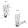
FIG. 4A is a cross-sectional view illustration of one embodiment of a pusher member in accordance with the present invention, showing the pusher member being used to manipulate a spinal fixation element to cause the feature on the spinal fixation element to sit within a spinal anchor attached to the access device, and to cause the remaining portion of the spinal fixation element to extend through the opening in an access device; -
FIG. 4B is a cross-sectional view illustration of the spinal fixation element shown inFIG. 4A being further manipulated to extend through the opening in the access device; -
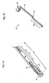
FIG. 5A is a side perspective view illustration of another embodiment of a pusher member in accordance with the present invention; -
FIG. 5B is a side perspective view illustration of an actuating member for use with the pusher member shown inFIG. 5A ; -
FIG. 5C is a side perspective view illustration of the pusher member ofFIG. 5A and the actuating member ofFIG. 5B , showing the actuating member being used to advance the pusher member from a proximal position to a distal position such that it is effective to cause a portion of a spinal fixation element to extend through the opening in the access device; -
FIG. 6A is a perspective view illustration of first and second access devices coupled to first and second spinal anchors implanted in adjacent vertebrae in a patient's spinal column, showing the spinal fixation element ofFIG. 1A being introduced through a proximal end of the first access device with the feature trailing; -
FIG. 6B is a perspective view illustration of the spinal fixation element shown inFIG. 6A being manipulated to extend through the opening of the first access device; and -
FIG. 6C is a perspective view illustration of the spinal fixation element shown inFIG. 6B being further manipulated to be positioned within the spinal anchor attached to the second access device and disposed within an adjacent vertebra. - The present invention provides a spinal fixation element, such as a spinal rod, having a feature formed thereon that facilitates placement of the spinal fixation element through an access device, thus allowing the spinal fixation element to be positioned in relation to a spinal anchor that is coupled to the access device and that is implanted in a vertebra in a patient's spine. The feature also optionally facilitates placement of the spinal fixation element in relation to one or more spinal anchors implanted in adjacent vertebrae. In particular, the spinal fixation element is adapted for use with an access device that has opposed openings formed therein and having a width that is less than a width of the feature, thus preventing the feature from passing therethrough. The spinal fixation element can therefore be inserted through the access device, and a portion of the fixation element can be passed through an opening in the access device while the feature is retained in the access device. As a result, the feature is seated within a spinal anchor that is coupled to the access device, and the remaining portion of the spinal fixation element can be positioned within a spinal anchor implanted in an adjacent vertebra.
-
FIG. 1A illustrates an exemplary embodiment of aspinal fixation element 10 in accordance with the present invention. As shown, thespinal fixation element 10 is in the form of an elongate spinal rod having opposed first and second terminal ends 10a, 10b. Thefixation element 10 can have any shape and size, and it can be substantially straight or it can have a curved profile, as shown, depending on the intended use. Thefixation element 10 also includes a feature that is preferably formed on or adjacent to aterminal end fixation element 10. While the feature can have any shape,FIG. 1A illustrates an exemplary embodiment of afeature 10c formed on thesecond end 10b of thefixation element 10 and having a generally spherical or bulbous shape, While not shown, thefeature 10c can optionally include a flattened portion that extends in a direction that is substantially perpendicular to a generally longitudinal axis Lr of thespinal fixation element 10. The use of a flattened portion is particularly advantageous in that it allows a closure mechanism to be applied to the receiver head of a spinal anchor containing thefeature 10c of thespinal fixation element 10, as will be discussed in more detail below. The size of thefeature 10c can also vary, but it should have a size that allows thefeature 10c to be captured within an access device, and that allows it to be disposed within a receiver head of a spinal anchor, which will also be discussed in more detail below. - A person skilled in the art will appreciate that the
feature 10c formed on thespinal fixation element 10 can have a variety of other configurations, and it can be formed anywhere on thespinal fixation element 10. By way of non-limiting example, thefeature 10c can be substantially square or rectangular, or it can have some other shape that protrudes outward from the spinal fixation element. By way of non-limiting example,FIG. 1C illustrates a spinal fixation element 10' having anannular protrusion 10c' formed therein. Regardless of the shape and size of the feature, the shape and size should be adapted to be captured by an access device used in connection with the spinal fixation element. - Virtually any access device can be used with a spinal fixation element in accordance with the present invention, and the configuration of the access device can vary depending on the configuration of the spinal fixation element, and in particular of the feature formed on the spinal fixation element. By way of non-limiting example,
FIG. 2A illustrates an exemplary embodiment of anaccess device 12 for use in connection with thespinal fixation element 10 shown inFIG. 1A . As shown, theaccess device 12 is in the form of a generally elongate, cylindrical tube having aninner lumen 12c formed therein and defining a longitudinal axis L that extends between proximal anddistal ends access device 12 can vary depending on the intended use, but it should have a length l that allows theproximal end 12a of theaccess device 12 to be positioned outside the patient's body, while thedistal end 12b of theaccess device 12 is coupled to, or positioned adjacent to, a spinal anchor that is implanted in a vertebra in a patient's spine. Theaccess device 12 is also preferably apercutaneous access device 12 such that it is adapted to provide a minimally invasive pathway for the delivery of a spinal fixation element therethrough. In particular, thepercutaneous access device 12 preferably has an outer diameter do that allows theaccess device 12 to be implanted through a minimally invasive percutaneous incision, which is a relatively small incision that typically has a length that is less than a diameter or width of the device being inserted therethrough. The inner diameter di of thedevice 12 can also vary, but it should be sufficient to allow thespinal fixation element 10 to be introduced therethrough, preferably in a lengthwise orientation. As will be discussed in more detail below, the inner diameter di can also be configured to allow a pusher member to be introduced therethrough for manipulating the spinal fixation element, and it can also be configured to allow a driver mechanism to be introduced therethrough for applying a closure mechanism to lock the spinal fixation element in relation to a spinal anchor. - As is further shown in
FIG. 2A , theaccess device 12 includes two opposed sidewall openings (only oneopening 14 is shown) formed therein and extending proximally from thedistal end 12b thereof. One or both openings can be configured for use withspinal fixation element 10, however only opening 14 is described herein. The shape and size of theopening 14 can vary depending on the shape and size of thefeature 10c on thespinal fixation element 10, but theopening 14 should be effective to capture thefeature 10c within theaccess device 12. More particularly, theopening 14 should have a width w that is less than a width wf of thefeature 10c on thespinal fixation element 10 to prevent passage of thefeature 10c therethrough, as shown inFIG. 1B . Theopening 14 can also extend over about half of the length l, or less than half of the length l, of theaccess device 12, but more preferably theopening 14 has a length lo that is greater than a length lr (FIG. 1A ) of thespinal fixation element 10. In use, thespinal fixation element 10 can be introduced through thedevice 12 in a first, lengthwise orientation, in which thespinal fixation element 10 is substantially parallel to the longitudinal axis L (FIG. 2B ) of theaccess device 12. Thefeature 10c will be retained within theaccess device 12, and the remainder of thespinal fixation element 10 can be manipulated to extend through theslot 14 in theaccess device 12 to position it in a second orientation at an angle with respect to the first orientation. Since the length L of thespinal fixation element 10 will necessarily be greater than the inner diameter di of theaccess device 12, theopening 14 allows thespinal fixation element 10 to pass therethrough while being transitioned from the first, lengthwise orientation to the second orientation. By capturing thefeature 10c within theaccess device 12, placement of the remainder of thespinal fixation element 10 within a spinal anchor implanted in an adjacent vertebra can be facilitated. - A person skilled in the art will appreciate that the
access device 12 can include more than two sidewall openings having any shape and size that is sufficient to allow a spinal fixation element in accordance with the present invention to be moved from the first orientation to the second orientation while preventing passage of the feature therethrough. - As indicated above, the
access device 12 is adapted to couple to aspinal anchor 50, as shown inFIG. 2B , to facilitate placement of thespinal fixation element 10 with respect to one or more spinal anchors implanted in adjacent vertebrae in a patient's spinal column. Accordingly, thedistal end 12c of theaccess device 12 can include one ormore mating elements 18 formed thereon or therein for engaging theanchor 50. Suitable mating elements include, for example, threads, a twist-lock engagement, a snap- on engagement, or any other technique known in the art, and in an exemplary embodiment the mating elements are formed on an inner surface of thedistal end 12b of theaccess device 12. Exemplary techniques for mating theaccess device 12 to an anchor are disclosed in U.S. Patent Publication No.US-2005/0131408 , entitled "Percutaneous Access Devices and Bone Anchor Assemblies," filed on December 16, 2003. A person skilled in the art will appreciate that a variety of other techniques can be used to removably mate the access device to an anchor. -
FIG. 2B further illustrates an exemplary spinal anchor, e.g.,spinal screw 50, for use with the devices of the present invention. Whilescrew 50 is shown, a variety of other anchors can be used with the devices of the present invention including, for example, spinal hooks, bolts, wires/cables, etc. As shown inFIG. 2B , thespinal screw 50 includes a distal, bone-engaging portion, e.g., a threadedshank 54, and a proximal, U-shaped,receiver head 52 that is adapted to seat thespinal fixation element 10, and more particularly that is adapted to seat thefeature 10c formed on thespinal fixation element 10. The threadedshank 54 can be fixedly attached to thereceiver head 52 to form a monoaxial screw, or alternatively theshank 54 can be configured as a polyaxial screw, as shown, that is rotatably disposed through an opening formed in the distal end of thereceiver head 52 to allow rotation of theshank 54 with respect to thereceiver head 52. A variety of techniques can be used to allow rotation of thehead 52 with respect to theshank 54. - Methods for implanting a spinal fixation element within one or more spinal anchors implanted in one or more adjacent vertebrae in a patient's spinal column are also disclosed. The methods do not fall within the scope of the present invention.. An exemplary method for implanting the spinal anchors and for attaching an access device to at least one of the anchors is described in more detail in U.S. Patent Publication No.
US-2005/0131421 , entitled "Methods and Devices for Minimally Invasive Spinal Fixation Element Placement," filed on December 16, 2003. A person skilled in the art will appreciate that, while the method is shown and described in connection withaccess device 12 andspinal screw 50 disclosed herein, the method is not limited to use with such devices, and a variety of other devices known in the art can be used. Moreover, while twoaccess devices 12, 12' and twoanchors 50, 50' are shown, the method can be performed using any number of access devices and anchors. The method can also be performed using only some of the method steps disclosed herein, and/or using other methods known in the art. -
FIG. 3A-3C illustrate one method for implanting a spinal fixation element having a feature formed thereon through an access device. As shown inFIG. 3A , thespinal fixation element 10 is inserted into thelumen 12c in theproximal end 12a of theaccess device 12 in a lengthwise orientation with thefeature 10c leading, and the opposed terminal end, e.g., thefirst end 10a, of thespinal fixation element 10 trailing. Thespinal fixation element 10 is then advanced toward thedistal end 12b of theaccess device 12 until thefeature 10c is positioned within thereceiver head 52 of thespinal anchor 50, as shown inFIG. 3B . The remainder of thefixation element 10 can then be manipulated to move it from the first, lengthwise orientation to a second orientation, in which thespinal fixation element 10 extends through theslot 14 formed in theaccess device 12. Since the feature has a width wf that is greater than a width w of theslot 14, the feature is retained within theaccess device 12, as is further shown inFIG. 3B . As a result, the remainder of thefixation element 10 can be positioned within a receiver head 52' of the spinal anchor 50' disposed within an adjacent vertebra, as shown inFIG. 3C . Thespinal fixation element 10 can then be locked to eachspinal anchor 50, 50', preferably by applying a closure mechanism (not shown) to thereceiver head 52, 52' of eachanchor 50, 50'. Virtually any closure mechanism can be used to lock thespinal fixation element 10 within eachreceiver head 52, 52' including, for example, a threaded or twist-lock closure cap. Where thefeature 10c on thefixation element 10 includes a flattened surface (not shown), the flattened surface should be positioned such that is faces theproximal end 12a of theaccess device 12, thus allowing the closure cap to rest against the flattened surface when it is applied to thereceiver head 52 on theanchor 50. - The present invention also provides a pusher member that can optionally be used to facilitate movement of the
fixation element 10 from the first to the second orientation. The pusher member can be an elongate member for advancing thespinal fixation element 10 in a distal direction, and/or it can include an engagement mechanism to engage and manipulate thespinal fixation element 10. By way of non-limiting example, U.S. Patent Publication No.US-2005/0131420 , entitled "Pivoting Implant Holder," filed on December 16, 2003, discloses various pusher members that can be used with the present invention. -
FIGS, 4A and 4B illustrate one exemplary embodiment of apusher member 60 for use with the present invention. As shown, thepusher member 60 is in the form of anelongate shaft 62 having adistal pusher portion 64 that is configured to be slidably disposed within thelumen 12c in theaccess device 12. Thedistal pusher portion 64 has a substantially wedge-like shape such that a distal-most surface of thedistal pusher portion 64 is disposed at an angle α with respect to a longitudinal axis Lp of thepusher member 60. This allows thepusher member 60 to direct thespinal fixation element 10 through theslot 14 in theaccess device 12, as shown inFIGS. 4A and 4B , thereby facilitating positioning of thespinal fixation element 10, preferably with respect to one or more spinal anchors implanted in adjacent vertebrae. -
FIGS. 5A-5C illustrate another embodiment of a pusher member for manipulating thespinal fixation element 10 to cause it to extend through theslot 14 formed in theaccess device 12. In this embodiment, the pusher member is in the form of apusher window 70 that is slidably disposed within a slot formed in theaccess device 12.FIG. 5A illustrates twoslots 14a, 14b formed in theaccess device 12, and thepusher window 70 is shown disposed withinslot 14a. Thepusher window 70 preferably only extends across a portion of theslot 14a, and in particular it preferably has a length lw that is less than a length ls of theslot 14a, only a portion of which is shown inFIG. 5A . In use, thepusher window 70 is movable along the longitudinal axis L of thedevice 12 between the first, proximal position, and a second, distal position. An actuating mechanism, such as a lever that is coupled to the slidingwindow 70, can be provided for controlling movement of the slidingwindow 70 between the first and second positions. While virtually any actuating member can be used,FIG. 5B illustrates an actuatingmember 72 having a proximal o-ring portion 74 that is adapted to be slidably disposed around theaccess device 12, and anelongate member 76 that extends distally from the proximal o-ring portion 74. Theelongate member 76 includes at least one bend 76a formed therein that allows a distal portion 76b of theelongate member 76 to extend into and be positioned within theslot 14a formed in theaccess device 12. In use, the o-ring 76 on the actuatingmember 72 is positioned around theaccess device 12 such that the distal portion 76b is seated within theslot 14a formed in theaccess device 12 at a position that is proximal to the position of thepusher window 70, as shown inFIG. 5C . The actuatingmember 72 can then be moved distally, thereby causing thepusher window 70 to move in a distal direction. When thespinal fixation element 10 is disposed within theaccess device 12, a trailing end, e.g.,first end 10a, will at least partially be positioned within theslot 14a. Thus, distal movement of thepusher window 70 will be effective to further guide thefixation device 10 through theslot 14a, preferably toward a spinal anchor that is implanted in an adjacent vertebra. Thepusher window 70 is particularly useful withspinal fixation elements 10 that have a curved configuration, as the curvature of thespinal fixation element 10 will cause a portion of thefixation element 10 to extend into theslot 14, thus allowing thepusher window 70 to engage thefixation element 10 and force it into the second orientation. -
FIG. 6A-6D illustrate another method for implanting a spinal fixation element having a feature formed thereon through an access device. The method does not fall within the scope of the present invention. In this embodiment, thespinal fixation element 10 is inserted into theaccess device 12 in a lengthwise orientation with thefeature 10c trailing, as shown inFIG. 6A . As thefixation element 10 approaches thedistal end 12b of theaccess device 12, as shown inFIG. 6B , thespinal fixation element 10 can be manipulated to cause thespinal fixation element 10 to transition to the second orientation. This is achieved by passing theleading end 10a of thespinal fixation element 10 through theslot 14 in theaccess device 12 as thefixation element 10 is moved distally. Further movement of thefixation element 10 will cause thefixation element 10 to be positioned in relation to one or more spinal anchors, and more preferably to extend between thespinal anchor 52 coupled to theaccess device 12 and a spinal anchor 52' implanted in an adjacent vertebra, as shown inFIG. 6C . As previously stated, a variety of pusher devices can be used to guide and/or manipulate thespinal fixation element 10 to extend through theslot 14. During transition of thespinal fixation element 10, thefeature 10c on thefixation element 10 will be captured by theaccess device 12 and thus it will be seated within thereceiver head 52 of thespinal anchor 50 that is coupled to theaccess device 12, as is also shown inFIG. 6C . A locking mechanism can then be applied to the spinal anchor(s) 50, 50' to lock thespinal fixation element 10 thereto. A person skilled in the art will appreciate that, depending on the type of spinal anchor used, thefixation element 10 can be positioned to be directly or indirectly mated to the spinal anchor(s) 50, 50'. - One skilled in the art will appreciate further features and advantages of the invention based on the above-described embodiments. Accordingly, the invention is not to be limited by what has been particularly shown and described, except as indicated by the appended claims.
Claims (10)
- A spinal implant kit, comprising:an access device (12) having an inner lumen (12c) extending between proximal (12a) and distal (12b) ends, and opposed openings (14a, 14b) formed in a sidewall thereof adjacent to the distal end, the sidewall openings extending from the distal end of the access device and terminating distal to the proximal end of the access device; anda spinal rod (10) having a feature (10c) formed thereon adjacent to a terminal end (10a, 10b) thereof, the feature being sized to prevent passage thereof through any portion of the openings in the access device.
- The spinal implant kit of claim 1, wherein the feature comprises a bulbous protrusion formed on the terminal end of the spinal rod.
- The spinal implant kit of claim 2, wherein the bulbous protrusion includes a substantially flattened portion.
- The spinal implant kit of claim 1, wherein the feature comprises a protrusion extending radially outward from the spinal rod.
- The spinal implant kit of claim 1, wherein the openings each have a length (lo) that is greater than a length (lr) of the spinal rod.
- The spinal implant kit of claim 1, further comprising a pusher member (60, 70) adapted to advance the spinal rod in a distal direction within the access device.
- The spinal implant kit of claim 6, wherein the pusher member (70) comprises an elongate shaft (76) having a proximal, handle portion and a distal portion (76b) that is slidably disposable within and extends into one of the openings (14a, 14b) in the sidewall of the access device.
- The spinal implant kit of claim 1, further comprising a pusher member (60, 70) that is slidably disposable within one of the openings in the sidewall of the access device such that it is effective to cause a portion of the spinal rod to extend through said opening.
- The spinal implant kit of claim 8, further comprising an actuating member (72) adapted to move the pusher member (70) between a first, proximal position and a second, distal position.
- The spinal implant kit of claim 2, wherein the bulbous protrusion has a diameter (Wf) that is greater than a width (W) of the openings in the access device.
Applications Claiming Priority (2)
| Application Number | Priority Date | Filing Date | Title |
|---|---|---|---|
| US10/708,721 US7547318B2 (en) | 2004-03-19 | 2004-03-19 | Spinal fixation element and methods |
| PCT/US2005/004208 WO2005094416A2 (en) | 2004-03-19 | 2005-02-10 | Spinal fixation element and methods |
Publications (3)
| Publication Number | Publication Date |
|---|---|
| EP1737366A2 EP1737366A2 (en) | 2007-01-03 |
| EP1737366A4 EP1737366A4 (en) | 2008-12-03 |
| EP1737366B1 true EP1737366B1 (en) | 2012-12-12 |
Family
ID=34991055
Family Applications (1)
| Application Number | Title | Priority Date | Filing Date |
|---|---|---|---|
| EP05713266A Not-in-force EP1737366B1 (en) | 2004-03-19 | 2005-02-10 | Spinal fixation element |
Country Status (6)
| Country | Link |
|---|---|
| US (2) | US7547318B2 (en) |
| EP (1) | EP1737366B1 (en) |
| JP (1) | JP4499152B2 (en) |
| AU (1) | AU2005227866B2 (en) |
| CA (1) | CA2559984C (en) |
| WO (1) | WO2005094416A2 (en) |
Cited By (2)
| Publication number | Priority date | Publication date | Assignee | Title |
|---|---|---|---|---|
| US9795422B2 (en) | 2016-01-06 | 2017-10-24 | Aesculap Implant Systems, Llc | Rod inserter, system and method |
| US9968387B2 (en) | 2016-01-06 | 2018-05-15 | Aesculap Implant Systems, Llc | Rod inserter, system and method |
Families Citing this family (166)
| Publication number | Priority date | Publication date | Assignee | Title |
|---|---|---|---|---|
| US6159179A (en) | 1999-03-12 | 2000-12-12 | Simonson; Robert E. | Cannula and sizing and insertion method |
| US7833250B2 (en) | 2004-11-10 | 2010-11-16 | Jackson Roger P | Polyaxial bone screw with helically wound capture connection |
| US7862587B2 (en) | 2004-02-27 | 2011-01-04 | Jackson Roger P | Dynamic stabilization assemblies, tool set and method |
| US7008431B2 (en) | 2001-10-30 | 2006-03-07 | Depuy Spine, Inc. | Configured and sized cannula |
| US7824410B2 (en) * | 2001-10-30 | 2010-11-02 | Depuy Spine, Inc. | Instruments and methods for minimally invasive spine surgery |
| US8876868B2 (en) | 2002-09-06 | 2014-11-04 | Roger P. Jackson | Helical guide and advancement flange with radially loaded lip |
| US7621918B2 (en) | 2004-11-23 | 2009-11-24 | Jackson Roger P | Spinal fixation tool set and method |
| US7377923B2 (en) | 2003-05-22 | 2008-05-27 | Alphatec Spine, Inc. | Variable angle spinal screw assembly |
| US7967850B2 (en) | 2003-06-18 | 2011-06-28 | Jackson Roger P | Polyaxial bone anchor with helical capture connection, insert and dual locking assembly |
| US7766915B2 (en) | 2004-02-27 | 2010-08-03 | Jackson Roger P | Dynamic fixation assemblies with inner core and outer coil-like member |
| US8926670B2 (en) | 2003-06-18 | 2015-01-06 | Roger P. Jackson | Polyaxial bone screw assembly |
| US8366753B2 (en) | 2003-06-18 | 2013-02-05 | Jackson Roger P | Polyaxial bone screw assembly with fixed retaining structure |
| US7776067B2 (en) | 2005-05-27 | 2010-08-17 | Jackson Roger P | Polyaxial bone screw with shank articulation pressure insert and method |
| US7955355B2 (en) | 2003-09-24 | 2011-06-07 | Stryker Spine | Methods and devices for improving percutaneous access in minimally invasive surgeries |
| US7875031B2 (en) * | 2003-09-24 | 2011-01-25 | Spinefrontier, LLS | System and method for implanting spinal stabilization devices |
| US8002798B2 (en) | 2003-09-24 | 2011-08-23 | Stryker Spine | System and method for spinal implant placement |
| US9055934B2 (en) | 2004-08-26 | 2015-06-16 | Zimmer Spine, Inc. | Methods and apparatus for access to and/or treatment of the spine |
| US7527638B2 (en) | 2003-12-16 | 2009-05-05 | Depuy Spine, Inc. | Methods and devices for minimally invasive spinal fixation element placement |
| US11419642B2 (en) | 2003-12-16 | 2022-08-23 | Medos International Sarl | Percutaneous access devices and bone anchor assemblies |
| US7179261B2 (en) | 2003-12-16 | 2007-02-20 | Depuy Spine, Inc. | Percutaneous access devices and bone anchor assemblies |
| US11241261B2 (en) | 2005-09-30 | 2022-02-08 | Roger P Jackson | Apparatus and method for soft spinal stabilization using a tensionable cord and releasable end structure |
| US8152810B2 (en) | 2004-11-23 | 2012-04-10 | Jackson Roger P | Spinal fixation tool set and method |
| US7160300B2 (en) | 2004-02-27 | 2007-01-09 | Jackson Roger P | Orthopedic implant rod reduction tool set and method |
| AU2004317551B2 (en) * | 2004-02-27 | 2008-12-04 | Roger P. Jackson | Orthopedic implant rod reduction tool set and method |
| US7547318B2 (en) * | 2004-03-19 | 2009-06-16 | Depuy Spine, Inc. | Spinal fixation element and methods |
| US7524323B2 (en) * | 2004-04-16 | 2009-04-28 | Kyphon Sarl | Subcutaneous support |
| US7618418B2 (en) * | 2004-04-16 | 2009-11-17 | Kyphon Sarl | Plate system for minimally invasive support of the spine |
| US7648520B2 (en) * | 2004-04-16 | 2010-01-19 | Kyphon Sarl | Pedicle screw assembly |
| US7811311B2 (en) * | 2004-12-30 | 2010-10-12 | Warsaw Orthopedic, Inc. | Screw with deployable interlaced dual rods |
| US7789899B2 (en) * | 2004-12-30 | 2010-09-07 | Warsaw Orthopedic, Inc. | Bone anchorage screw with built-in hinged plate |
| US7651496B2 (en) * | 2004-07-23 | 2010-01-26 | Zimmer Spine, Inc. | Methods and apparatuses for percutaneous implant delivery |
| US7641690B2 (en) * | 2004-08-23 | 2010-01-05 | Abdou M Samy | Bone fixation and fusion device |
| EP1814472B1 (en) * | 2004-09-08 | 2018-10-24 | NuVasive, Inc. | Systems for performing spinal fixation |
| US7651502B2 (en) | 2004-09-24 | 2010-01-26 | Jackson Roger P | Spinal fixation tool set and method for rod reduction and fastener insertion |
| US7666189B2 (en) * | 2004-09-29 | 2010-02-23 | Synthes Usa, Llc | Less invasive surgical system and methods |
| US7951153B2 (en) | 2004-10-05 | 2011-05-31 | Samy Abdou | Devices and methods for inter-vertebral orthopedic device placement |
| US7935134B2 (en) | 2004-10-20 | 2011-05-03 | Exactech, Inc. | Systems and methods for stabilization of bone structures |
| US8162985B2 (en) | 2004-10-20 | 2012-04-24 | The Board Of Trustees Of The Leland Stanford Junior University | Systems and methods for posterior dynamic stabilization of the spine |
| US8025680B2 (en) | 2004-10-20 | 2011-09-27 | Exactech, Inc. | Systems and methods for posterior dynamic stabilization of the spine |
| US8226690B2 (en) | 2005-07-22 | 2012-07-24 | The Board Of Trustees Of The Leland Stanford Junior University | Systems and methods for stabilization of bone structures |
| US8267969B2 (en) | 2004-10-20 | 2012-09-18 | Exactech, Inc. | Screw systems and methods for use in stabilization of bone structures |
| US7604655B2 (en) | 2004-10-25 | 2009-10-20 | X-Spine Systems, Inc. | Bone fixation system and method for using the same |
| EP1814473B1 (en) | 2004-10-25 | 2012-12-05 | X-spine Systems, Inc. | Pedicle screw systems |
| US8075591B2 (en) * | 2004-11-09 | 2011-12-13 | Depuy Spine, Inc. | Minimally invasive spinal fixation guide systems and methods |
| US8926672B2 (en) | 2004-11-10 | 2015-01-06 | Roger P. Jackson | Splay control closure for open bone anchor |
| US9168069B2 (en) | 2009-06-15 | 2015-10-27 | Roger P. Jackson | Polyaxial bone anchor with pop-on shank and winged insert with lower skirt for engaging a friction fit retainer |
| WO2006057837A1 (en) | 2004-11-23 | 2006-06-01 | Jackson Roger P | Spinal fixation tool attachment structure |
| US8444681B2 (en) | 2009-06-15 | 2013-05-21 | Roger P. Jackson | Polyaxial bone anchor with pop-on shank, friction fit retainer and winged insert |
| EP1814474B1 (en) | 2004-11-24 | 2011-09-14 | Samy Abdou | Devices for inter-vertebral orthopedic device placement |
| US8403962B2 (en) | 2005-02-22 | 2013-03-26 | Roger P. Jackson | Polyaxial bone screw assembly |
| US7901437B2 (en) | 2007-01-26 | 2011-03-08 | Jackson Roger P | Dynamic stabilization member with molded connection |
| WO2006091863A2 (en) * | 2005-02-23 | 2006-08-31 | Pioneer Laboratories, Inc. | Minimally invasive surgical system |
| WO2008024937A2 (en) | 2006-08-23 | 2008-02-28 | Pioneer Surgical Technology, Inc. | Minimally invasive surgical system |
| ES2318917B1 (en) * | 2005-03-30 | 2010-02-04 | Sdgi Holdings Inc. | SYSTEM FOR THE THREE-DIMENSIONAL CORRECTION OF THE CURVATURE OF THE VERTEBRAL COLUMN IN PROBLEMS OF SCHOLIOSIS BY COPLANAR ALIGNMENT OF THE PEDICULAR SCREWS. |
| US7758617B2 (en) * | 2005-04-27 | 2010-07-20 | Globus Medical, Inc. | Percutaneous vertebral stabilization system |
| US8177817B2 (en) * | 2005-05-18 | 2012-05-15 | Stryker Spine | System and method for orthopedic implant configuration |
| US8523865B2 (en) | 2005-07-22 | 2013-09-03 | Exactech, Inc. | Tissue splitter |
| US7717943B2 (en) | 2005-07-29 | 2010-05-18 | X-Spine Systems, Inc. | Capless multiaxial screw and spinal fixation assembly and method |
| US7909830B2 (en) | 2005-08-25 | 2011-03-22 | Synthes Usa, Llc | Methods of spinal fixation and instrumentation |
| US7686835B2 (en) | 2005-10-04 | 2010-03-30 | X-Spine Systems, Inc. | Pedicle screw system with provisional locking aspects |
| WO2007044705A2 (en) | 2005-10-07 | 2007-04-19 | Abdou Samy M | Devices and methods for inter-verterbral orthopedic device placement |
| US20070191841A1 (en) * | 2006-01-27 | 2007-08-16 | Sdgi Holdings, Inc. | Spinal rods having different flexural rigidities about different axes and methods of use |
| US7497869B2 (en) | 2006-01-27 | 2009-03-03 | Warsaw Orthopedic, Inc. | Methods and devices for a minimally invasive placement of a rod within a patient |
| US8894655B2 (en) | 2006-02-06 | 2014-11-25 | Stryker Spine | Rod contouring apparatus and method for percutaneous pedicle screw extension |
| AU2007238129A1 (en) | 2006-04-11 | 2007-10-25 | Synthes Gmbh | Minimally invasive fixation system |
| US7563274B2 (en) * | 2006-04-25 | 2009-07-21 | Warsaw Orthopedic, Inc. | Surgical instruments and techniques for controlling spinal motion segments with positioning of spinal stabilization elements |
| WO2008014015A2 (en) * | 2006-07-26 | 2008-01-31 | Jen-Lin Chen | Data-storing media case |
| US8303630B2 (en) | 2006-07-27 | 2012-11-06 | Samy Abdou | Devices and methods for the minimally invasive treatment of spinal stenosis |
| US8038699B2 (en) * | 2006-09-26 | 2011-10-18 | Ebi, Llc | Percutaneous instrument assembly |
| US8162952B2 (en) * | 2006-09-26 | 2012-04-24 | Ebi, Llc | Percutaneous instrument assembly |
| US8197488B2 (en) * | 2006-10-16 | 2012-06-12 | Depuy Spine, Inc. | Automatic locking casper distractor |
| US8096996B2 (en) | 2007-03-20 | 2012-01-17 | Exactech, Inc. | Rod reducer |
| US8052720B2 (en) * | 2006-11-09 | 2011-11-08 | Zimmer Spine, Inc. | Minimally invasive pedicle screw access system and associated method |
| US8262662B2 (en) | 2006-11-20 | 2012-09-11 | Depuy Spine, Inc. | Break-off screw extensions |
| US7931673B2 (en) * | 2006-12-06 | 2011-04-26 | Zimmer Spine, Inc. | Minimally invasive vertebral anchor access system and associated method |
| AU2007332794C1 (en) | 2006-12-08 | 2012-01-12 | Roger P. Jackson | Tool system for dynamic spinal implants |
| US20080234765A1 (en) * | 2007-03-13 | 2008-09-25 | Depuy Spine, Inc. | Rod reduction methods and devices |
| US7648521B2 (en) * | 2007-03-15 | 2010-01-19 | Zimmer Spine, Inc. | System and method for minimally invasive spinal surgery |
| EP2146654A4 (en) | 2007-03-27 | 2011-09-28 | X Spine Systems Inc | Pedicle screw system configured to receive a straight or a curved rod |
| US8460300B2 (en) * | 2007-06-12 | 2013-06-11 | Zimmer Spine, Inc. | Instrumentation and associated techniques for minimally invasive vertebral rod installation |
| US20080312704A1 (en) * | 2007-06-12 | 2008-12-18 | Zimmer Spine, Inc. | Instrumentation and associated techniques for minimally invasive spinal construct installation |
| US8361126B2 (en) | 2007-07-03 | 2013-01-29 | Pioneer Surgical Technology, Inc. | Bone plate system |
| WO2009006604A1 (en) | 2007-07-03 | 2009-01-08 | Pioneer Surgical Technology, Inc. | Bone plate system |
| US20090082811A1 (en) * | 2007-09-26 | 2009-03-26 | Depuy Spine, Inc. | Devices and methods for positioning a spinal fixation element |
| US8414588B2 (en) | 2007-10-04 | 2013-04-09 | Depuy Spine, Inc. | Methods and devices for minimally invasive spinal connection element delivery |
| US9232968B2 (en) | 2007-12-19 | 2016-01-12 | DePuy Synthes Products, Inc. | Polymeric pedicle rods and methods of manufacturing |
| US8439922B1 (en) | 2008-02-06 | 2013-05-14 | NiVasive, Inc. | Systems and methods for holding and implanting bone anchors |
| US8932210B2 (en) * | 2008-02-28 | 2015-01-13 | K2M, Inc. | Minimally invasive retraction device having detachable blades |
| US8747407B2 (en) | 2008-02-28 | 2014-06-10 | K2M, Inc. | Minimally invasive retractor and methods of use |
| US8097026B2 (en) | 2008-02-28 | 2012-01-17 | K2M, Inc. | Minimally invasive retraction device having removable blades |
| US8246538B2 (en) * | 2008-02-28 | 2012-08-21 | K2M, Inc. | Minimally invasive retractor with separable blades and methods of use |
| US20090222044A1 (en) * | 2008-02-28 | 2009-09-03 | K2M, Inc. | Minimally Invasive Retractor Screw and Methods of Use |
| US20090221879A1 (en) * | 2008-02-28 | 2009-09-03 | K2M, Inc. | Minimally Invasive Retractor Having Separable Blades |
| JP2012529969A (en) | 2008-08-01 | 2012-11-29 | ロジャー・ピー・ジャクソン | Longitudinal connecting member with tensioning cord with sleeve |
| US20100036432A1 (en) * | 2008-08-05 | 2010-02-11 | Abbott Spine Inc. | Twist off reduction screw |
| BRPI0920821B8 (en) | 2008-10-01 | 2021-06-22 | Hua Sherwin | bone stabilization system and screw for use in bone stabilization |
| US8882807B2 (en) * | 2008-10-03 | 2014-11-11 | Us Spine, Inc. | Minimally invasive surgery pedicle screw system |
| US8439923B2 (en) * | 2008-10-17 | 2013-05-14 | Omni Surgical LLC | Poly-axial pedicle screw assembly |
| US8641734B2 (en) | 2009-02-13 | 2014-02-04 | DePuy Synthes Products, LLC | Dual spring posterior dynamic stabilization device with elongation limiting elastomers |
| US9750545B2 (en) | 2009-03-27 | 2017-09-05 | Globus Medical, Inc. | Devices and methods for inserting a vertebral fixation member |
| US8900238B2 (en) * | 2009-03-27 | 2014-12-02 | Globus Medical, Inc. | Devices and methods for inserting a vertebral fixation member |
| US8206394B2 (en) | 2009-05-13 | 2012-06-26 | Depuy Spine, Inc. | Torque limited instrument for manipulating a spinal rod relative to a bone anchor |
| US9808281B2 (en) | 2009-05-20 | 2017-11-07 | DePuy Synthes Products, Inc. | Patient-mounted retraction |
| US11229457B2 (en) | 2009-06-15 | 2022-01-25 | Roger P. Jackson | Pivotal bone anchor assembly with insert tool deployment |
| EP2753252A1 (en) | 2009-06-15 | 2014-07-16 | Jackson, Roger P. | Polyaxial bone anchor with pop-on shank and friction fit retainer with low profile edge lock |
| US8998959B2 (en) | 2009-06-15 | 2015-04-07 | Roger P Jackson | Polyaxial bone anchors with pop-on shank, fully constrained friction fit retainer and lock and release insert |
| US9668771B2 (en) | 2009-06-15 | 2017-06-06 | Roger P Jackson | Soft stabilization assemblies with off-set connector |
| CN103826560A (en) | 2009-06-15 | 2014-05-28 | 罗杰.P.杰克逊 | Polyaxial bone anchor with pop-on shank and winged insert with friction fit compressive collet |
| US9320543B2 (en) | 2009-06-25 | 2016-04-26 | DePuy Synthes Products, Inc. | Posterior dynamic stabilization device having a mobile anchor |
| US9655658B2 (en) * | 2009-10-14 | 2017-05-23 | Ebi, Llc | Deformable device for minimally invasive fixation |
| US8236032B2 (en) * | 2009-10-20 | 2012-08-07 | Depuy Spine, Inc. | Spinal implant with a flexible extension element |
| WO2011057178A1 (en) | 2009-11-06 | 2011-05-12 | Dean Lin | System and method for stabilizing and fixating lumbar vertebrae |
| US8795335B1 (en) | 2009-11-06 | 2014-08-05 | Samy Abdou | Spinal fixation devices and methods of use |
| US8764806B2 (en) | 2009-12-07 | 2014-07-01 | Samy Abdou | Devices and methods for minimally invasive spinal stabilization and instrumentation |
| US8540719B2 (en) | 2010-02-09 | 2013-09-24 | Aesculap Implant Systems, Llc | Percutaneous rod insertion system and method |
| US9445844B2 (en) | 2010-03-24 | 2016-09-20 | DePuy Synthes Products, Inc. | Composite material posterior dynamic stabilization spring rod |
| AU2011232543B2 (en) | 2010-03-26 | 2015-11-19 | Echostar Technologies L.L.C. | Multiple input television receiver |
| KR101814838B1 (en) | 2010-03-30 | 2018-01-03 | 셔윈 화 | Systems and methods for pedicle screw stabilization of spinal vertebrae |
| US8956414B2 (en) | 2010-04-21 | 2015-02-17 | Spinecraft, LLC | Intervertebral body implant, instrument and method |
| US8535318B2 (en) | 2010-04-23 | 2013-09-17 | DePuy Synthes Products, LLC | Minimally invasive instrument set, devices and related methods |
| CN102293680B (en) | 2010-06-24 | 2014-04-16 | 华沙整形外科股份有限公司 | Coplanar straightening system |
| US20120016424A1 (en) * | 2010-07-19 | 2012-01-19 | Warsaw Orthopedic, Inc. | Extensions for spinal anchors |
| US8603094B2 (en) | 2010-07-26 | 2013-12-10 | Spinal Usa, Inc. | Minimally invasive surgical tower access devices and related methods |
| US9198698B1 (en) | 2011-02-10 | 2015-12-01 | Nuvasive, Inc. | Minimally invasive spinal fixation system and related methods |
| CN103717159B (en) | 2011-05-27 | 2016-08-17 | 新特斯有限责任公司 | Minimally invasive spine fixed system including vertebrae aligned feature |
| US8968319B2 (en) | 2011-06-20 | 2015-03-03 | Spinefrontier, Inc | Methods, tools and devices for spinal fixation |
| US8845728B1 (en) | 2011-09-23 | 2014-09-30 | Samy Abdou | Spinal fixation devices and methods of use |
| US9198769B2 (en) | 2011-12-23 | 2015-12-01 | Pioneer Surgical Technology, Inc. | Bone anchor assembly, bone plate system, and method |
| WO2013106217A1 (en) | 2012-01-10 | 2013-07-18 | Jackson, Roger, P. | Multi-start closures for open implants |
| US8936626B1 (en) | 2012-02-17 | 2015-01-20 | Nuvasive, Inc. | Bi-cortical screw fixation |
| US20130226240A1 (en) | 2012-02-22 | 2013-08-29 | Samy Abdou | Spinous process fixation devices and methods of use |
| US20130345757A1 (en) | 2012-06-22 | 2013-12-26 | Shawn D. Stad | Image Guided Intra-Operative Contouring Aid |
| US9198767B2 (en) | 2012-08-28 | 2015-12-01 | Samy Abdou | Devices and methods for spinal stabilization and instrumentation |
| US9320617B2 (en) | 2012-10-22 | 2016-04-26 | Cogent Spine, LLC | Devices and methods for spinal stabilization and instrumentation |
| US8911478B2 (en) | 2012-11-21 | 2014-12-16 | Roger P. Jackson | Splay control closure for open bone anchor |
| US10058354B2 (en) | 2013-01-28 | 2018-08-28 | Roger P. Jackson | Pivotal bone anchor assembly with frictional shank head seating surfaces |
| US8852239B2 (en) | 2013-02-15 | 2014-10-07 | Roger P Jackson | Sagittal angle screw with integral shank and receiver |
| US9827020B2 (en) | 2013-03-14 | 2017-11-28 | Stryker European Holdings I, Llc | Percutaneous spinal cross link system and method |
| US9510875B2 (en) | 2013-03-14 | 2016-12-06 | Stryker European Holdings I, Llc | Systems and methods for percutaneous spinal fusion |
| EP3054871B1 (en) | 2013-10-07 | 2022-05-18 | K2M, Inc. | Rod reducer |
| US9566092B2 (en) | 2013-10-29 | 2017-02-14 | Roger P. Jackson | Cervical bone anchor with collet retainer and outer locking sleeve |
| US10159579B1 (en) | 2013-12-06 | 2018-12-25 | Stryker European Holdings I, Llc | Tubular instruments for percutaneous posterior spinal fusion systems and methods |
| US9408716B1 (en) | 2013-12-06 | 2016-08-09 | Stryker European Holdings I, Llc | Percutaneous posterior spinal fusion implant construction and method |
| US9744050B1 (en) | 2013-12-06 | 2017-08-29 | Stryker European Holdings I, Llc | Compression and distraction system for percutaneous posterior spinal fusion |
| US9717533B2 (en) | 2013-12-12 | 2017-08-01 | Roger P. Jackson | Bone anchor closure pivot-splay control flange form guide and advancement structure |
| US9451993B2 (en) | 2014-01-09 | 2016-09-27 | Roger P. Jackson | Bi-radial pop-on cervical bone anchor |
| WO2015145343A1 (en) | 2014-03-26 | 2015-10-01 | Medacta International Sa | Device for implanting a surgical screw |
| US9597119B2 (en) | 2014-06-04 | 2017-03-21 | Roger P. Jackson | Polyaxial bone anchor with polymer sleeve |
| US10064658B2 (en) | 2014-06-04 | 2018-09-04 | Roger P. Jackson | Polyaxial bone anchor with insert guides |
| US10034690B2 (en) | 2014-12-09 | 2018-07-31 | John A. Heflin | Spine alignment system |
| US9943344B2 (en) | 2015-01-15 | 2018-04-17 | K2M, Inc. | Rod reducer |
| WO2016175885A1 (en) | 2015-04-30 | 2016-11-03 | K2M, Inc. | Rod reducer |
| US9974577B1 (en) | 2015-05-21 | 2018-05-22 | Nuvasive, Inc. | Methods and instruments for performing leveraged reduction during single position spine surgery |
| US9439692B1 (en) | 2015-10-09 | 2016-09-13 | Spine Wave, Inc. | Minimally invasive spinal fixation system and method therefor |
| US10857003B1 (en) | 2015-10-14 | 2020-12-08 | Samy Abdou | Devices and methods for vertebral stabilization |
| CN107019512B (en) * | 2016-01-28 | 2022-05-24 | 皇家飞利浦有限公司 | Fixing mechanism and MRI system |
| US10524843B2 (en) | 2016-05-06 | 2020-01-07 | K2M, Inc. | Rotation shaft for a rod reducer |
| US10398481B2 (en) | 2016-10-03 | 2019-09-03 | Nuvasive, Inc. | Spinal fixation system |
| US10744000B1 (en) | 2016-10-25 | 2020-08-18 | Samy Abdou | Devices and methods for vertebral bone realignment |
| US10973648B1 (en) | 2016-10-25 | 2021-04-13 | Samy Abdou | Devices and methods for vertebral bone realignment |
| US10779866B2 (en) | 2016-12-29 | 2020-09-22 | K2M, Inc. | Rod reducer assembly |
| US10485590B2 (en) | 2017-01-18 | 2019-11-26 | K2M, Inc. | Rod reducing device |
| US11051861B2 (en) | 2018-06-13 | 2021-07-06 | Nuvasive, Inc. | Rod reduction assemblies and related methods |
| US11179248B2 (en) | 2018-10-02 | 2021-11-23 | Samy Abdou | Devices and methods for spinal implantation |
| US11160580B2 (en) | 2019-04-24 | 2021-11-02 | Spine23 Inc. | Systems and methods for pedicle screw stabilization of spinal vertebrae |
| US11877779B2 (en) | 2020-03-26 | 2024-01-23 | Xtant Medical Holdings, Inc. | Bone plate system |
Family Cites Families (107)
| Publication number | Priority date | Publication date | Assignee | Title |
|---|---|---|---|---|
| US2320709A (en) | 1941-08-01 | 1943-06-01 | Nat Electric Instr Co Inc | Speculum |
| US3246646A (en) | 1962-10-31 | 1966-04-19 | Cordis Corp | Pivoted vaginal speculum having linear and angular blade adjusting means |
| US3552799A (en) | 1969-07-18 | 1971-01-05 | North American Car Corp | Sparger type unloading apparatus for railroad cars |
| US4156424A (en) | 1978-05-01 | 1979-05-29 | Burgin Kermit H | Locking adjustable speculum |
| US4545374A (en) * | 1982-09-03 | 1985-10-08 | Jacobson Robert E | Method and instruments for performing a percutaneous lumbar diskectomy |
| DE8418588U1 (en) | 1984-06-15 | 1984-10-04 | Mecron Medizinische Produkte Gmbh, 1000 Berlin | screw |
| US4887020A (en) | 1984-07-23 | 1989-12-12 | U.S. Philips Corporation | Self-compensating brushless alternator |
| DE8609189U1 (en) | 1986-02-24 | 1986-05-15 | Tsai, Joy Yih-Chiou, Tung Shih, Taichung | DUCKBILL SPECTRUM |
| SU1459658A1 (en) | 1986-04-24 | 1989-02-23 | Благовещенский государственный медицинский институт | Retractor |
| US4872451A (en) | 1987-02-02 | 1989-10-10 | Moore Robert R | Glenohumeral ligament repair |
| US4913134A (en) | 1987-07-24 | 1990-04-03 | Biotechnology, Inc. | Spinal fixation system |
| US5052372A (en) | 1988-04-05 | 1991-10-01 | Shapiro Jerome J | Vaginal speculum having a unique single control |
| US4961740B1 (en) | 1988-10-17 | 1997-01-14 | Surgical Dynamics Inc | V-thread fusion cage and method of fusing a bone joint |
| US5062845A (en) | 1989-05-10 | 1991-11-05 | Spine-Tech, Inc. | Method of making an intervertebral reamer |
| AT395940B (en) | 1989-10-25 | 1993-04-26 | Ender Hans Georg | BONE NAIL AND TOOL FOR THE SAME |
| US5231973A (en) | 1989-12-21 | 1993-08-03 | Advanced Medical Devices Incorporated | Vaginal speculum |
| US5024659A (en) | 1990-01-10 | 1991-06-18 | Smith & Nephew Dyonics Inc. | Breakable needle and hinged needle guide |
| WO1991016020A1 (en) * | 1990-04-26 | 1991-10-31 | Danninger Medical Technology, Inc. | Transpedicular screw system and method of use |
| FR2676911B1 (en) * | 1991-05-30 | 1998-03-06 | Psi Ste Civile Particuliere | INTERVERTEBRAL STABILIZATION DEVICE WITH SHOCK ABSORBERS. |
| US5520610A (en) | 1991-05-31 | 1996-05-28 | Giglio; Steven R. | Self retaining retractor |
| US5242443A (en) | 1991-08-15 | 1993-09-07 | Smith & Nephew Dyonics, Inc. | Percutaneous fixation of vertebrae |
| US5395317A (en) | 1991-10-30 | 1995-03-07 | Smith & Nephew Dyonics, Inc. | Unilateral biportal percutaneous surgical procedure |
| US5766221A (en) | 1991-12-03 | 1998-06-16 | Boston Scientific Technology, Inc. | Bone anchor implantation device |
| US5439467A (en) | 1991-12-03 | 1995-08-08 | Vesica Medical, Inc. | Suture passer |
| US5242446A (en) | 1992-01-02 | 1993-09-07 | Acromed Corporation | Connector for a spinal column corrective device |
| US5171279A (en) | 1992-03-17 | 1992-12-15 | Danek Medical | Method for subcutaneous suprafascial pedicular internal fixation |
| US5324290A (en) | 1992-09-24 | 1994-06-28 | Danek Medical, Inc. | Anterior thoracolumbar plate |
| US5484440A (en) * | 1992-11-03 | 1996-01-16 | Zimmer, Inc. | Bone screw and screwdriver |
| FR2729291B1 (en) | 1995-01-12 | 1997-09-19 | Euros Sa | RACHIDIAN IMPLANT |
| US5520690A (en) | 1995-04-13 | 1996-05-28 | Errico; Joseph P. | Anterior spinal polyaxial locking screw plate assembly |
| US5669911A (en) | 1995-04-13 | 1997-09-23 | Fastenetix, L.L.C. | Polyaxial pedicle screw |
| US5792044A (en) | 1996-03-22 | 1998-08-11 | Danek Medical, Inc. | Devices and methods for percutaneous surgery |
| FR2748386B1 (en) * | 1996-05-09 | 1998-11-20 | Breard Francis Henri | ANTI-TRIP SYSTEM FOR SPINE ARTHRODESIS BAR |
| IES77331B2 (en) * | 1997-06-03 | 1997-12-03 | Tecos Holdings Inc | Pluridirectional and modulable vertebral osteosynthesis device of small overall size |
| US6053921A (en) * | 1997-08-26 | 2000-04-25 | Spinal Concepts, Inc. | Surgical cable system and method |
| US6004326A (en) * | 1997-09-10 | 1999-12-21 | United States Surgical | Method and instrumentation for implant insertion |
| US6226548B1 (en) | 1997-09-24 | 2001-05-01 | Surgical Navigation Technologies, Inc. | Percutaneous registration apparatus and method for use in computer-assisted surgical navigation |
| US5931777A (en) | 1998-03-11 | 1999-08-03 | Sava; Gerard A. | Tissue retractor and method for use |
| DE29806563U1 (en) | 1998-04-09 | 1998-06-18 | Howmedica Gmbh | Pedicle screw and assembly aid for it |
| US5928139A (en) | 1998-04-24 | 1999-07-27 | Koros; Tibor B. | Retractor with adjustable length blades and light pipe guides |
| US6224548B1 (en) | 1998-05-26 | 2001-05-01 | Ineedmd.Com, Inc. | Tele-diagnostic device |
| DE29810798U1 (en) | 1998-06-17 | 1999-10-28 | Schaefer Micomed Gmbh | Osteosynthesis device |
| US6139493A (en) | 1998-07-08 | 2000-10-31 | Koros; Tibor B. | Retractor with adjustable length blades and light pipe guides |
| US6224545B1 (en) | 1998-07-24 | 2001-05-01 | Core Surgical, Inc. | Surgical retractor and method for use |
| US6187000B1 (en) | 1998-08-20 | 2001-02-13 | Endius Incorporated | Cannula for receiving surgical instruments |
| US6530926B1 (en) * | 2000-08-01 | 2003-03-11 | Endius Incorporated | Method of securing vertebrae |
| US6652527B2 (en) | 1998-10-20 | 2003-11-25 | St. Francis Medical Technologies, Inc. | Supplemental spine fixation device and method |
| DE29819914U1 (en) | 1998-11-07 | 1999-01-07 | Aesculap Ag & Co Kg | Endoscopic insertion instruments |
| US6250322B1 (en) | 1999-02-16 | 2001-06-26 | William H. Porter | Umbrella-shaped shelter |
| US6159179A (en) | 1999-03-12 | 2000-12-12 | Simonson; Robert E. | Cannula and sizing and insertion method |
| US6607530B1 (en) | 1999-05-10 | 2003-08-19 | Highgate Orthopedics, Inc. | Systems and methods for spinal fixation |
| US7122036B2 (en) | 1999-07-01 | 2006-10-17 | Spinevision, S.A. | Connector for an osteosynthesis system intended to provide a connection between two rods of a spinal osteosynthesis system, osteosynthesis system using such a connector, and method of implanting such an osteosynthesis system |
| FR2796545B1 (en) | 1999-07-22 | 2002-03-15 | Dimso Sa | POLY-AXIAL LINK FOR OSTEOSYNTHESIS SYSTEM, ESPECIALLY FOR THE RACHIS |
| US6200322B1 (en) * | 1999-08-13 | 2001-03-13 | Sdgi Holdings, Inc. | Minimal exposure posterior spinal interbody instrumentation and technique |
| WO2001022893A1 (en) | 1999-09-27 | 2001-04-05 | Blackstone Medical, Inc. | A surgical screw system and related methods |
| US6530929B1 (en) | 1999-10-20 | 2003-03-11 | Sdgi Holdings, Inc. | Instruments for stabilization of bony structures |
| US6331179B1 (en) | 2000-01-06 | 2001-12-18 | Spinal Concepts, Inc. | System and method for stabilizing the human spine with a bone plate |
| US6235028B1 (en) | 2000-02-14 | 2001-05-22 | Sdgi Holdings, Inc. | Surgical guide rod |
| DE10027988C2 (en) | 2000-06-06 | 2003-08-21 | Arkadiusz Kosmala | Device for stereotaxically guided percutaneous implantation of the longitudinal connection of the pedicle screws |
| JP2002083999A (en) | 2000-06-21 | 2002-03-22 | Sharp Corp | Light emitting semiconductor element |
| US6964667B2 (en) | 2000-06-23 | 2005-11-15 | Sdgi Holdings, Inc. | Formed in place fixation system with thermal acceleration |
| US6899713B2 (en) | 2000-06-23 | 2005-05-31 | Vertelink Corporation | Formable orthopedic fixation system |
| US6749614B2 (en) | 2000-06-23 | 2004-06-15 | Vertelink Corporation | Formable orthopedic fixation system with cross linking |
| US6821277B2 (en) | 2000-06-23 | 2004-11-23 | University Of Southern California Patent And Copyright Administration | Percutaneous vertebral fusion system |
| US6554831B1 (en) | 2000-09-01 | 2003-04-29 | Hopital Sainte-Justine | Mobile dynamic system for treating spinal disorder |
| US6485491B1 (en) | 2000-09-15 | 2002-11-26 | Sdgi Holdings, Inc. | Posterior fixation system |
| US6755829B1 (en) | 2000-09-22 | 2004-06-29 | Depuy Acromed, Inc. | Lock cap anchor assembly for orthopaedic fixation |
| US6692434B2 (en) | 2000-09-29 | 2004-02-17 | Stephen Ritland | Method and device for retractor for microsurgical intermuscular lumbar arthrodesis |
| US6743231B1 (en) | 2000-10-02 | 2004-06-01 | Sulzer Spine-Tech Inc. | Temporary spinal fixation apparatuses and methods |
| US6951538B2 (en) | 2001-01-29 | 2005-10-04 | Depuy Spine, Inc. | Retractor and method for spinal pedicle screw placement |
| DE10108965B4 (en) | 2001-02-17 | 2006-02-23 | DePuy Spine Sàrl | bone screw |
| US6929647B2 (en) | 2001-02-21 | 2005-08-16 | Howmedica Osteonics Corp. | Instrumentation and method for implant insertion |
| US6802844B2 (en) | 2001-03-26 | 2004-10-12 | Nuvasive, Inc | Spinal alignment apparatus and methods |
| US20030194371A1 (en) | 2001-07-10 | 2003-10-16 | Schering Ag | (Ethylene)-(propylene) - triaminepentaacetic acid derivatives, process for their production, and their use for the production of pharmaceutical agents |
| US6916330B2 (en) | 2001-10-30 | 2005-07-12 | Depuy Spine, Inc. | Non cannulated dilators |
| US7008431B2 (en) | 2001-10-30 | 2006-03-07 | Depuy Spine, Inc. | Configured and sized cannula |
| US6783527B2 (en) | 2001-10-30 | 2004-08-31 | Sdgi Holdings, Inc. | Flexible spinal stabilization system and method |
| US6740089B2 (en) | 2002-01-10 | 2004-05-25 | Thomas T. Haider | Orthopedic hook system |
| US7261688B2 (en) | 2002-04-05 | 2007-08-28 | Warsaw Orthopedic, Inc. | Devices and methods for percutaneous tissue retraction and surgery |
| US6740086B2 (en) | 2002-04-18 | 2004-05-25 | Spinal Innovations, Llc | Screw and rod fixation assembly and device |
| US7572276B2 (en) | 2002-05-06 | 2009-08-11 | Warsaw Orthopedic, Inc. | Minimally invasive instruments and methods for inserting implants |
| US6682529B2 (en) * | 2002-06-11 | 2004-01-27 | Stahurski Consulting, Inc. | Connector assembly with multidimensional accommodation and associated method |
| US7306603B2 (en) * | 2002-08-21 | 2007-12-11 | Innovative Spinal Technologies | Device and method for percutaneous placement of lumbar pedicle screws and connecting rods |
| US8876868B2 (en) | 2002-09-06 | 2014-11-04 | Roger P. Jackson | Helical guide and advancement flange with radially loaded lip |
| US6849064B2 (en) | 2002-10-25 | 2005-02-01 | James S. Hamada | Minimal access lumbar diskectomy instrumentation and method |
| CA2502571C (en) | 2002-10-30 | 2011-10-18 | Spinal Concepts, Inc. | Spinal stabilization system insertion and methods |
| US20040162560A1 (en) | 2003-02-19 | 2004-08-19 | Raynor Donald E. | Implant device including threaded locking mechanism |
| DE10322142A1 (en) * | 2003-05-16 | 2004-12-09 | Siemens Ag | Radioscopy instrument for medical diagnostic imaging, has laser distance meter for measuring distance between source and patient, and has computer for automatic exposure calculation |
| US20050001340A1 (en) * | 2003-05-30 | 2005-01-06 | Page John K. | Apparatus for the preparation of liquids for the dispense of beverages |
| US7819880B2 (en) | 2003-06-30 | 2010-10-26 | Depuy Products, Inc. | Implant delivery instrument |
| US7691120B2 (en) | 2003-08-26 | 2010-04-06 | Zimmer Spine, Inc. | Access systems and methods for minimally invasive surgery |
| US7955355B2 (en) | 2003-09-24 | 2011-06-07 | Stryker Spine | Methods and devices for improving percutaneous access in minimally invasive surgeries |
| US7588588B2 (en) * | 2003-10-21 | 2009-09-15 | Innovative Spinal Technologies | System and method for stabilizing of internal structures |
| US20050131406A1 (en) * | 2003-12-15 | 2005-06-16 | Archus Orthopedics, Inc. | Polyaxial adjustment of facet joint prostheses |
| US7179261B2 (en) | 2003-12-16 | 2007-02-20 | Depuy Spine, Inc. | Percutaneous access devices and bone anchor assemblies |
| US7527638B2 (en) | 2003-12-16 | 2009-05-05 | Depuy Spine, Inc. | Methods and devices for minimally invasive spinal fixation element placement |
| US20050131407A1 (en) | 2003-12-16 | 2005-06-16 | Sicvol Christopher W. | Flexible spinal fixation elements |
| US7648507B2 (en) | 2003-12-16 | 2010-01-19 | Depuy Acromed, Inc. | Pivoting implant holder |
| US7666188B2 (en) * | 2003-12-16 | 2010-02-23 | Depuy Spine, Inc. | Methods and devices for spinal fixation element placement |
| US7597694B2 (en) | 2004-01-30 | 2009-10-06 | Warsaw Orthopedic, Inc. | Instruments and methods for minimally invasive spinal stabilization |
| WO2005076868A2 (en) * | 2004-02-06 | 2005-08-25 | Depuy Spine, Inc. | Devices and methods for inserting a spinal fixation element |
| US7160300B2 (en) | 2004-02-27 | 2007-01-09 | Jackson Roger P | Orthopedic implant rod reduction tool set and method |
| US7470279B2 (en) | 2004-02-27 | 2008-12-30 | Jackson Roger P | Orthopedic implant rod reduction tool set and method |
| US7547318B2 (en) | 2004-03-19 | 2009-06-16 | Depuy Spine, Inc. | Spinal fixation element and methods |
| EP1814472B1 (en) * | 2004-09-08 | 2018-10-24 | NuVasive, Inc. | Systems for performing spinal fixation |
| US7727260B2 (en) * | 2005-03-24 | 2010-06-01 | Accelerated Innovation, Llc | Method and apparatus for bone stabilization |
| WO2007149426A2 (en) * | 2006-06-16 | 2007-12-27 | Alphatec Spine, Inc. | Systems and methods for manipulating and/or installing a pedicle screw |
-
2004
- 2004-03-19 US US10/708,721 patent/US7547318B2/en active Active
-
2005
- 2005-02-10 CA CA2559984A patent/CA2559984C/en not_active Expired - Fee Related
- 2005-02-10 AU AU2005227866A patent/AU2005227866B2/en not_active Ceased
- 2005-02-10 JP JP2007503904A patent/JP4499152B2/en not_active Expired - Fee Related
- 2005-02-10 EP EP05713266A patent/EP1737366B1/en not_active Not-in-force
- 2005-02-10 WO PCT/US2005/004208 patent/WO2005094416A2/en not_active Application Discontinuation
-
2009
- 2009-05-11 US US12/463,578 patent/US8828005B2/en active Active
Cited By (2)
| Publication number | Priority date | Publication date | Assignee | Title |
|---|---|---|---|---|
| US9795422B2 (en) | 2016-01-06 | 2017-10-24 | Aesculap Implant Systems, Llc | Rod inserter, system and method |
| US9968387B2 (en) | 2016-01-06 | 2018-05-15 | Aesculap Implant Systems, Llc | Rod inserter, system and method |
Also Published As
| Publication number | Publication date |
|---|---|
| CA2559984A1 (en) | 2005-10-13 |
| US20050215999A1 (en) | 2005-09-29 |
| AU2005227866A1 (en) | 2005-10-13 |
| JP4499152B2 (en) | 2010-07-07 |
| WO2005094416A2 (en) | 2005-10-13 |
| JP2007529268A (en) | 2007-10-25 |
| EP1737366A4 (en) | 2008-12-03 |
| AU2005227866B2 (en) | 2010-08-26 |
| EP1737366A2 (en) | 2007-01-03 |
| US7547318B2 (en) | 2009-06-16 |
| CA2559984C (en) | 2010-05-18 |
| US20090216328A1 (en) | 2009-08-27 |
| WO2005094416A3 (en) | 2006-12-07 |
| US8828005B2 (en) | 2014-09-09 |
Similar Documents
| Publication | Publication Date | Title |
|---|---|---|
| EP1737366B1 (en) | Spinal fixation element | |
| US11241262B2 (en) | Methods and devices for spinal fixation element placement | |
| US8262662B2 (en) | Break-off screw extensions | |
| US9750547B2 (en) | Methods and devices for minimally invasive spinal fixation element placement | |
| US9101416B2 (en) | Spinal rod approximator | |
| CA2548729C (en) | Methods and devices for minimally invasive spinal fixation element placement |
Legal Events
| Date | Code | Title | Description |
|---|---|---|---|
| PUAI | Public reference made under article 153(3) epc to a published international application that has entered the european phase |
Free format text: ORIGINAL CODE: 0009012 |
|
| PUAK | Availability of information related to the publication of the international search report |
Free format text: ORIGINAL CODE: 0009015 |
|
| 17P | Request for examination filed |
Effective date: 20060825 |
|
| AK | Designated contracting states |
Kind code of ref document: A2 Designated state(s): AT BE BG CH CY CZ DE DK EE ES FI FR GB GR HU IE IS IT LI LT LU MC NL PL PT RO SE SI SK TR |
|
| AX | Request for extension of the european patent |
Extension state: AL BA HR LV MK YU |
|
| RIC1 | Information provided on ipc code assigned before grant |
Ipc: A61B 17/56 20060101AFI20070115BHEP |
|
| DAX | Request for extension of the european patent (deleted) | ||
| A4 | Supplementary search report drawn up and despatched |
Effective date: 20081030 |
|
| 17Q | First examination report despatched |
Effective date: 20090519 |
|
| REG | Reference to a national code |
Ref country code: DE Ref legal event code: R079 Ref document number: 602005037388 Country of ref document: DE Free format text: PREVIOUS MAIN CLASS: A61B0017580000 Ipc: A61B0017700000 |
|
| GRAP | Despatch of communication of intention to grant a patent |
Free format text: ORIGINAL CODE: EPIDOSNIGR1 |
|
| RIC1 | Information provided on ipc code assigned before grant |
Ipc: A61B 17/70 20060101AFI20120601BHEP |
|
| GRAS | Grant fee paid |
Free format text: ORIGINAL CODE: EPIDOSNIGR3 |
|
| GRAA | (expected) grant |
Free format text: ORIGINAL CODE: 0009210 |
|
| AK | Designated contracting states |
Kind code of ref document: B1 Designated state(s): AT BE BG CH CY CZ DE DK EE ES FI FR GB GR HU IE IS IT LI LT LU MC NL PL PT RO SE SI SK TR |
|
| REG | Reference to a national code |
Ref country code: GB Ref legal event code: FG4D |
|
| REG | Reference to a national code |
Ref country code: CH Ref legal event code: EP |
|
| REG | Reference to a national code |
Ref country code: AT Ref legal event code: REF Ref document number: 587958 Country of ref document: AT Kind code of ref document: T Effective date: 20121215 |
|
| REG | Reference to a national code |
Ref country code: IE Ref legal event code: FG4D |
|
| REG | Reference to a national code |
Ref country code: DE Ref legal event code: R096 Ref document number: 602005037388 Country of ref document: DE Effective date: 20130207 |
|
| PG25 | Lapsed in a contracting state [announced via postgrant information from national office to epo] |
Ref country code: SE Free format text: LAPSE BECAUSE OF FAILURE TO SUBMIT A TRANSLATION OF THE DESCRIPTION OR TO PAY THE FEE WITHIN THE PRESCRIBED TIME-LIMIT Effective date: 20121212 Ref country code: FI Free format text: LAPSE BECAUSE OF FAILURE TO SUBMIT A TRANSLATION OF THE DESCRIPTION OR TO PAY THE FEE WITHIN THE PRESCRIBED TIME-LIMIT Effective date: 20121212 Ref country code: LT Free format text: LAPSE BECAUSE OF FAILURE TO SUBMIT A TRANSLATION OF THE DESCRIPTION OR TO PAY THE FEE WITHIN THE PRESCRIBED TIME-LIMIT Effective date: 20121212 Ref country code: ES Free format text: LAPSE BECAUSE OF FAILURE TO SUBMIT A TRANSLATION OF THE DESCRIPTION OR TO PAY THE FEE WITHIN THE PRESCRIBED TIME-LIMIT Effective date: 20130323 |
|
| PGFP | Annual fee paid to national office [announced via postgrant information from national office to epo] |
Ref country code: CH Payment date: 20130212 Year of fee payment: 9 Ref country code: FR Payment date: 20130301 Year of fee payment: 9 |
|
| REG | Reference to a national code |
Ref country code: NL Ref legal event code: VDEP Effective date: 20121212 |
|
| REG | Reference to a national code |
Ref country code: AT Ref legal event code: MK05 Ref document number: 587958 Country of ref document: AT Kind code of ref document: T Effective date: 20121212 |
|
| REG | Reference to a national code |
Ref country code: LT Ref legal event code: MG4D |
|
| PG25 | Lapsed in a contracting state [announced via postgrant information from national office to epo] |
Ref country code: GR Free format text: LAPSE BECAUSE OF FAILURE TO SUBMIT A TRANSLATION OF THE DESCRIPTION OR TO PAY THE FEE WITHIN THE PRESCRIBED TIME-LIMIT Effective date: 20130313 Ref country code: SI Free format text: LAPSE BECAUSE OF FAILURE TO SUBMIT A TRANSLATION OF THE DESCRIPTION OR TO PAY THE FEE WITHIN THE PRESCRIBED TIME-LIMIT Effective date: 20121212 |
|
| PGFP | Annual fee paid to national office [announced via postgrant information from national office to epo] |
Ref country code: NL Payment date: 20130209 Year of fee payment: 9 |
|
| PG25 | Lapsed in a contracting state [announced via postgrant information from national office to epo] |
Ref country code: CZ Free format text: LAPSE BECAUSE OF FAILURE TO SUBMIT A TRANSLATION OF THE DESCRIPTION OR TO PAY THE FEE WITHIN THE PRESCRIBED TIME-LIMIT Effective date: 20121212 Ref country code: AT Free format text: LAPSE BECAUSE OF FAILURE TO SUBMIT A TRANSLATION OF THE DESCRIPTION OR TO PAY THE FEE WITHIN THE PRESCRIBED TIME-LIMIT Effective date: 20121212 Ref country code: EE Free format text: LAPSE BECAUSE OF FAILURE TO SUBMIT A TRANSLATION OF THE DESCRIPTION OR TO PAY THE FEE WITHIN THE PRESCRIBED TIME-LIMIT Effective date: 20121212 Ref country code: IS Free format text: LAPSE BECAUSE OF FAILURE TO SUBMIT A TRANSLATION OF THE DESCRIPTION OR TO PAY THE FEE WITHIN THE PRESCRIBED TIME-LIMIT Effective date: 20130412 Ref country code: BE Free format text: LAPSE BECAUSE OF FAILURE TO SUBMIT A TRANSLATION OF THE DESCRIPTION OR TO PAY THE FEE WITHIN THE PRESCRIBED TIME-LIMIT Effective date: 20121212 Ref country code: BG Free format text: LAPSE BECAUSE OF FAILURE TO SUBMIT A TRANSLATION OF THE DESCRIPTION OR TO PAY THE FEE WITHIN THE PRESCRIBED TIME-LIMIT Effective date: 20130312 Ref country code: SK Free format text: LAPSE BECAUSE OF FAILURE TO SUBMIT A TRANSLATION OF THE DESCRIPTION OR TO PAY THE FEE WITHIN THE PRESCRIBED TIME-LIMIT Effective date: 20121212 |
|
| PG25 | Lapsed in a contracting state [announced via postgrant information from national office to epo] |
Ref country code: RO Free format text: LAPSE BECAUSE OF FAILURE TO SUBMIT A TRANSLATION OF THE DESCRIPTION OR TO PAY THE FEE WITHIN THE PRESCRIBED TIME-LIMIT Effective date: 20121212 Ref country code: PT Free format text: LAPSE BECAUSE OF FAILURE TO SUBMIT A TRANSLATION OF THE DESCRIPTION OR TO PAY THE FEE WITHIN THE PRESCRIBED TIME-LIMIT Effective date: 20130412 Ref country code: NL Free format text: LAPSE BECAUSE OF FAILURE TO SUBMIT A TRANSLATION OF THE DESCRIPTION OR TO PAY THE FEE WITHIN THE PRESCRIBED TIME-LIMIT Effective date: 20121212 Ref country code: PL Free format text: LAPSE BECAUSE OF FAILURE TO SUBMIT A TRANSLATION OF THE DESCRIPTION OR TO PAY THE FEE WITHIN THE PRESCRIBED TIME-LIMIT Effective date: 20121212 |
|
| PG25 | Lapsed in a contracting state [announced via postgrant information from national office to epo] |
Ref country code: MC Free format text: LAPSE BECAUSE OF NON-PAYMENT OF DUE FEES Effective date: 20130228 |
|
| PLBE | No opposition filed within time limit |
Free format text: ORIGINAL CODE: 0009261 |
|
| STAA | Information on the status of an ep patent application or granted ep patent |
Free format text: STATUS: NO OPPOSITION FILED WITHIN TIME LIMIT |
|
| PG25 | Lapsed in a contracting state [announced via postgrant information from national office to epo] |
Ref country code: DK Free format text: LAPSE BECAUSE OF FAILURE TO SUBMIT A TRANSLATION OF THE DESCRIPTION OR TO PAY THE FEE WITHIN THE PRESCRIBED TIME-LIMIT Effective date: 20121212 |
|
| 26N | No opposition filed |
Effective date: 20130913 |
|
| PG25 | Lapsed in a contracting state [announced via postgrant information from national office to epo] |
Ref country code: CY Free format text: LAPSE BECAUSE OF FAILURE TO SUBMIT A TRANSLATION OF THE DESCRIPTION OR TO PAY THE FEE WITHIN THE PRESCRIBED TIME-LIMIT Effective date: 20121212 |
|
| REG | Reference to a national code |
Ref country code: IE Ref legal event code: MM4A |
|
| PG25 | Lapsed in a contracting state [announced via postgrant information from national office to epo] |
Ref country code: IT Free format text: LAPSE BECAUSE OF FAILURE TO SUBMIT A TRANSLATION OF THE DESCRIPTION OR TO PAY THE FEE WITHIN THE PRESCRIBED TIME-LIMIT Effective date: 20121212 |
|
| REG | Reference to a national code |
Ref country code: DE Ref legal event code: R097 Ref document number: 602005037388 Country of ref document: DE Effective date: 20130913 |
|
| PG25 | Lapsed in a contracting state [announced via postgrant information from national office to epo] |
Ref country code: IE Free format text: LAPSE BECAUSE OF NON-PAYMENT OF DUE FEES Effective date: 20130210 |
|
| REG | Reference to a national code |
Ref country code: CH Ref legal event code: PL |
|
| PG25 | Lapsed in a contracting state [announced via postgrant information from national office to epo] |
Ref country code: CH Free format text: LAPSE BECAUSE OF NON-PAYMENT OF DUE FEES Effective date: 20140228 Ref country code: LI Free format text: LAPSE BECAUSE OF NON-PAYMENT OF DUE FEES Effective date: 20140228 |
|
| REG | Reference to a national code |
Ref country code: FR Ref legal event code: ST Effective date: 20141031 |
|
| PG25 | Lapsed in a contracting state [announced via postgrant information from national office to epo] |
Ref country code: FR Free format text: LAPSE BECAUSE OF NON-PAYMENT OF DUE FEES Effective date: 20140228 |
|
| PG25 | Lapsed in a contracting state [announced via postgrant information from national office to epo] |
Ref country code: TR Free format text: LAPSE BECAUSE OF FAILURE TO SUBMIT A TRANSLATION OF THE DESCRIPTION OR TO PAY THE FEE WITHIN THE PRESCRIBED TIME-LIMIT Effective date: 20121212 |
|
| PG25 | Lapsed in a contracting state [announced via postgrant information from national office to epo] |
Ref country code: HU Free format text: LAPSE BECAUSE OF FAILURE TO SUBMIT A TRANSLATION OF THE DESCRIPTION OR TO PAY THE FEE WITHIN THE PRESCRIBED TIME-LIMIT; INVALID AB INITIO Effective date: 20050210 Ref country code: LU Free format text: LAPSE BECAUSE OF NON-PAYMENT OF DUE FEES Effective date: 20130210 |
|
| PGFP | Annual fee paid to national office [announced via postgrant information from national office to epo] |
Ref country code: GB Payment date: 20211230 Year of fee payment: 18 |
|
| PGFP | Annual fee paid to national office [announced via postgrant information from national office to epo] |
Ref country code: DE Payment date: 20211230 Year of fee payment: 18 |
|
| REG | Reference to a national code |
Ref country code: DE Ref legal event code: R119 Ref document number: 602005037388 Country of ref document: DE |
|
| GBPC | Gb: european patent ceased through non-payment of renewal fee |
Effective date: 20230210 |
|
| PG25 | Lapsed in a contracting state [announced via postgrant information from national office to epo] |
Ref country code: GB Free format text: LAPSE BECAUSE OF NON-PAYMENT OF DUE FEES Effective date: 20230210 |
|
| PG25 | Lapsed in a contracting state [announced via postgrant information from national office to epo] |
Ref country code: GB Free format text: LAPSE BECAUSE OF NON-PAYMENT OF DUE FEES Effective date: 20230210 Ref country code: DE Free format text: LAPSE BECAUSE OF NON-PAYMENT OF DUE FEES Effective date: 20230901 |