EP1736204A1 - Phototherapy apparatus with the function of change-over to different wavelength - Google Patents
Phototherapy apparatus with the function of change-over to different wavelength Download PDFInfo
- Publication number
- EP1736204A1 EP1736204A1 EP05013576A EP05013576A EP1736204A1 EP 1736204 A1 EP1736204 A1 EP 1736204A1 EP 05013576 A EP05013576 A EP 05013576A EP 05013576 A EP05013576 A EP 05013576A EP 1736204 A1 EP1736204 A1 EP 1736204A1
- Authority
- EP
- European Patent Office
- Prior art keywords
- light
- emitting diodes
- circuit board
- different wavelength
- change
- Prior art date
- Legal status (The legal status is an assumption and is not a legal conclusion. Google has not performed a legal analysis and makes no representation as to the accuracy of the status listed.)
- Withdrawn
Links
- 238000001126 phototherapy Methods 0.000 title claims abstract description 38
- 230000005855 radiation Effects 0.000 claims abstract description 44
- 239000000084 colloidal system Substances 0.000 claims description 4
- 238000012544 monitoring process Methods 0.000 claims description 2
- 230000002500 effect on skin Effects 0.000 description 5
- 230000000694 effects Effects 0.000 description 5
- 210000004204 blood vessel Anatomy 0.000 description 3
- 239000000049 pigment Substances 0.000 description 3
- 230000000191 radiation effect Effects 0.000 description 3
- 230000015572 biosynthetic process Effects 0.000 description 2
- 238000001816 cooling Methods 0.000 description 2
- 238000000034 method Methods 0.000 description 2
- 238000001228 spectrum Methods 0.000 description 2
- 206010052140 Eye pruritus Diseases 0.000 description 1
- 206010023644 Lacrimation increased Diseases 0.000 description 1
- 206010028735 Nasal congestion Diseases 0.000 description 1
- 208000007684 Occupational Stress Diseases 0.000 description 1
- 208000036071 Rhinorrhea Diseases 0.000 description 1
- 206010039101 Rhinorrhoea Diseases 0.000 description 1
- 238000010521 absorption reaction Methods 0.000 description 1
- 238000001720 action spectrum Methods 0.000 description 1
- 238000013459 approach Methods 0.000 description 1
- 238000006243 chemical reaction Methods 0.000 description 1
- 238000013461 design Methods 0.000 description 1
- 238000010586 diagram Methods 0.000 description 1
- 235000005911 diet Nutrition 0.000 description 1
- 230000000378 dietary effect Effects 0.000 description 1
- 201000010099 disease Diseases 0.000 description 1
- 208000037265 diseases, disorders, signs and symptoms Diseases 0.000 description 1
- 239000006185 dispersion Substances 0.000 description 1
- 238000005530 etching Methods 0.000 description 1
- 239000004744 fabric Substances 0.000 description 1
- 230000001815 facial effect Effects 0.000 description 1
- 230000007803 itching Effects 0.000 description 1
- 238000012986 modification Methods 0.000 description 1
- 230000004048 modification Effects 0.000 description 1
- 238000012545 processing Methods 0.000 description 1
- 238000011160 research Methods 0.000 description 1
- 208000017520 skin disease Diseases 0.000 description 1
- 206010041232 sneezing Diseases 0.000 description 1
- 230000000638 stimulation Effects 0.000 description 1
- 230000008961 swelling Effects 0.000 description 1
Images


Classifications
-
- A—HUMAN NECESSITIES
- A61—MEDICAL OR VETERINARY SCIENCE; HYGIENE
- A61N—ELECTROTHERAPY; MAGNETOTHERAPY; RADIATION THERAPY; ULTRASOUND THERAPY
- A61N5/00—Radiation therapy
- A61N5/06—Radiation therapy using light
- A61N5/0613—Apparatus adapted for a specific treatment
- A61N5/0616—Skin treatment other than tanning
-
- A—HUMAN NECESSITIES
- A61—MEDICAL OR VETERINARY SCIENCE; HYGIENE
- A61B—DIAGNOSIS; SURGERY; IDENTIFICATION
- A61B18/00—Surgical instruments, devices or methods for transferring non-mechanical forms of energy to or from the body
- A61B18/18—Surgical instruments, devices or methods for transferring non-mechanical forms of energy to or from the body by applying electromagnetic radiation, e.g. microwaves
- A61B18/20—Surgical instruments, devices or methods for transferring non-mechanical forms of energy to or from the body by applying electromagnetic radiation, e.g. microwaves using laser
- A61B18/203—Surgical instruments, devices or methods for transferring non-mechanical forms of energy to or from the body by applying electromagnetic radiation, e.g. microwaves using laser applying laser energy to the outside of the body
-
- A—HUMAN NECESSITIES
- A61—MEDICAL OR VETERINARY SCIENCE; HYGIENE
- A61B—DIAGNOSIS; SURGERY; IDENTIFICATION
- A61B18/00—Surgical instruments, devices or methods for transferring non-mechanical forms of energy to or from the body
- A61B2018/00315—Surgical instruments, devices or methods for transferring non-mechanical forms of energy to or from the body for treatment of particular body parts
- A61B2018/00452—Skin
- A61B2018/00458—Deeper parts of the skin, e.g. treatment of vascular disorders or port wine stains
-
- A—HUMAN NECESSITIES
- A61—MEDICAL OR VETERINARY SCIENCE; HYGIENE
- A61N—ELECTROTHERAPY; MAGNETOTHERAPY; RADIATION THERAPY; ULTRASOUND THERAPY
- A61N5/00—Radiation therapy
- A61N5/06—Radiation therapy using light
- A61N2005/0635—Radiation therapy using light characterised by the body area to be irradiated
- A61N2005/0643—Applicators, probes irradiating specific body areas in close proximity
- A61N2005/0644—Handheld applicators
-
- A—HUMAN NECESSITIES
- A61—MEDICAL OR VETERINARY SCIENCE; HYGIENE
- A61N—ELECTROTHERAPY; MAGNETOTHERAPY; RADIATION THERAPY; ULTRASOUND THERAPY
- A61N5/00—Radiation therapy
- A61N5/06—Radiation therapy using light
- A61N2005/065—Light sources therefor
- A61N2005/0651—Diodes
- A61N2005/0652—Arrays of diodes
-
- A—HUMAN NECESSITIES
- A61—MEDICAL OR VETERINARY SCIENCE; HYGIENE
- A61N—ELECTROTHERAPY; MAGNETOTHERAPY; RADIATION THERAPY; ULTRASOUND THERAPY
- A61N5/00—Radiation therapy
- A61N5/06—Radiation therapy using light
- A61N2005/0658—Radiation therapy using light characterised by the wavelength of light used
- A61N2005/0659—Radiation therapy using light characterised by the wavelength of light used infrared
-
- A—HUMAN NECESSITIES
- A61—MEDICAL OR VETERINARY SCIENCE; HYGIENE
- A61N—ELECTROTHERAPY; MAGNETOTHERAPY; RADIATION THERAPY; ULTRASOUND THERAPY
- A61N5/00—Radiation therapy
- A61N5/06—Radiation therapy using light
- A61N2005/0658—Radiation therapy using light characterised by the wavelength of light used
- A61N2005/0662—Visible light
- A61N2005/0663—Coloured light
Definitions
- the invention relates to a phototherapy apparatus with the function of change-over to different wavelength, and more particularly to a phototherapy apparatus that can be changed over to different wavelength for treatment. Meanwhile, a well-distributed radiation is ensured to avoid the formation of shadow areas due to the absence of radiation.
- IPL Intense Pulsed Light
- Intense Pulsed Light began in the year of 1990.
- the action spectrum of the Intense Pulsed Light (IPL) is very wide und it is the light whose wavelength ranges from 550nm to 1200nm.
- the spectrum of visible light and the infrared light are also included in the spectrum of the Intense Pulsed Light.
- the Intense Pulsed Light Compared with the laser beam, the Intense Pulsed Light has the similar energy and wavelength, but the range of its wavelength is larger.
- the system of Intense Pulsed Light (IPL) can select the relevant light to cure the different dermal problems. For example, the light with color from yellow to orange can exert its effect on the red blood vessel in the skin and the red light can remove the pigment.
- the Intense Pulsed Light can select an arbitrary light with suitable wavelength to carry out the treatment for different dermal problem, such as the expansion of blood vessel (redness-removal), the pigment treatment (spot-removal) and the stimulation of the fabric root cell in the derma (younger treatment) etc.
- the treatment results of spots, the uneven pigment, the expansion of blood vessel, the reddish face, the rough skin without flexibility, etc. are also very satisfactory.
- IPL Intense Pulsed Light
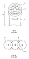
- a conventional phototherapy apparatus has a housing 11 on which a radiation head 12 is mounted.
- a plurality of light-emitting diodes 13 with a preset wavelength is installed in the radiation head 12.
- the conventional radiation head 12 has a circular contour. So, a plurality of shadow areas 14 due to the absence of radiation marked by dashed line will be created (see FIG. 2). To reduce the radiation shadow areas 14 as much as possible, will, however, result in intersection areas 15 that would make the local skin reddish and swelling.
- a phototherapy apparatus with the function of change-over to different wavelength comprises:
- the phototherapy apparatus in accordance with the invention further comprises a light cone that is attached with a mounting portion thereof onto the radiation head.
- the light cone is tapered from the mounting portion to a light exit that corresponds to the human nose in size.
- the phototherapy apparatus in accordance with the invention can be used as a BioNase.
- an embodiment of a phototherapy apparatus in accordance with the invention includes a housing 20 that permit an ergonomic holding of the apparatus, and a radiation head 30 that is disposed on a top side of the housing 20. It's preferable that the housing 20 and the radiation head 30 are integrally formed, but should not be restricted thereto. Alternatively, the radiation head 30 may be individually formed and then attached to the housing 20.
- the radiation head 30 includes a translucent cap 31 that is put onto the radiation head 30 from inside to outside, but should not be restricted thereto. Alternatively, the translucent cap 31 may be mounted on the radiation head 30 from outside to inside. Besides, the translucent cap 31 may be attached to the radiation head 30 by use of the high frequency processing. This belongs to the prior art so that no further descriptions thereto are given hereinafter.
- a plurality of light-emitting diodes 40 is electrically coupled to a circuit board 50 that is disposed within the radiation head 30.
- the circuit board 50 enables the light-emitting diodes 40 to emit light beams in direction to the translucent cap 31.
- the radiation head 30 and the translucent cap 31 in accordance with the invention are formed with a rectangular contour. Meanwhile, the four corners of thereof can be chamfered, but should not restricted thereto.
- the rectangular design of the invention can avoid the formation of the shadow areas 14 due to the absence of radiation (see FIG. 2) and ensure a well-distributed radiation effect with more light-emitting diodes 40 on the circuit board 50.
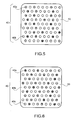
- the invention features that the light-emitting diodes 40 consists of light-emitting diodes 40a, 40b having different wavelength. Meanwhile, the light-emitting diodes 40a, 40b are arranged in a staggered manner on the circuit board 50.
- the light-emitting diodes 40 include the light-emitting diodes 40a with a first wavelength and the light-emitting diodes 40b with a second wavelength.
- the light-emitting diodes 40 include the light-emitting diodes 40a with a first wavelength, the light-emitting diodes 40b with a second wavelength and the light-emitting diodes 40c with a third wavelength.
- the third embodiment of the light-emitting diodes 40a, 40b, 40c with three kinds of wavelength is preferable, but should not be restricted thereto.
- the staggered arrangement of the light-emitting diodes with different wavelength can be done in such a way that each individual light-emitting diode or each row of the light-emitting diodes is offset from the other under the condition that the light-emitting diodes 40 of each kind of wavelength achieve a sufficient and well-distributed radiation effect.
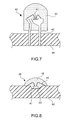
- the light-emitting diode 40 is made in such a way that LED die 41 is packaged by translucent colloid 42 and electrically coupled to the circuit board 50 via connecting feet 43.
- the light-emitting diodes 40 as shown in FIG. 8, the LED die 41 is stuck to a recess 52 formed on the surface of the circuit board 50. Then, the LED die 41 is wire-bonded to the circuit board 50 und packaged by the translucent colloid 42 in place.
- the recess 52 serves as a reflection surface with which the radiation beam can be reflected upwards.
- the circuit board 50 includes a plurality of cooing ribs 51 at a bottom surface thereof to enhance the cooling effect of the circuit board 50.
- the cooing ribs 51 may be replaced by other cooling apparatuses.
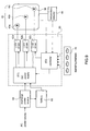
- an LED control circuit 60 is disposed within a receiving chamber 21 to supply power to the circuit board 50 and to enable the light-emitting action of one group of the light-emitting diodes 40a, 40b, 40c on the circuit board 50.
- the LED control circuit 60 includes a DC power supply 61, a plurality of LED driver 62a, 62b, 62c, and a controller 63.
- the DC power supply 61 is adapted to supply power to the light-emitting diodes 40 on the circuit board 50.
- the DC power is created by an exchange power source 64 that converts an alternating current into 1.5 V - 4.5V direct current.
- the DC power may be supplied by a battery 65 within the housing 20.
- the battery 65 can be replaced by a secondary battery that is recharged by the exchange power source 64 to supply the DC power.
- the LED driver 62a, 62b, 62c are interposed between the DC power supply 61 and the circuit board 50 to put the light-emitting diodes 40a, 40b, 40c in operation, respectively.
- the controller 63 is coupled to an operating interface 70 and adapted to control the LED driver 62a, 62b, 62c to activate the light-emitting diodes 40a, 40b, 40c, respectively.
- a temperature detector 66 is interposed between the controller 63 of the LED control circuit 60 and the circuit board 50 for monitoring the temperature of the light-emitting diodes 40 when they light up, thereby preventing the overtemperature from damaging the human skin.
- the controller 63 closes all of the light-emitting diodes 40 for ensuring a better safety in use.
- the operating interface 70 is mounted on the surface of the housing 20 and adapted to permit a free choice of one group of the light-emitting diodes 40a, 40b, 40c.
- the operating interface 70 includes a plurality of push buttons, but should not be restricted thereto.
- the operating interface 70 can be configured as a change-over type operating interface.
- At least three light-emitting diodes of different wavelength are available, thereby creating an application example of a multifunctional phototherapy apparatus as shown in FIG. 10.
- the operator holds the housing 20 with his hand and depresses one of the push buttons on the operating interface 70 to choose a radiation light beam with desired wavelength to apply to the skin.
- the first wavelength 300 - 330 nm for ultraviolet rays the second one is 630 - 660 um for infrared rays
- the third one is 860 um for invisible rays.
- a fourth wavelength of 470 nm for blue rays can be added to the invention. This won't be more described hereinafter.
- Each light wave has its own function, and a suitable one should be chosen by a professional physician. This doesn't belong to the object of the invention so that no further descriptions are given hereinafter.
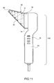
- a light cone 80 is added to the phototherapy apparatus.
- the light cone 80 includes a mounting portion 81 that is mounted on the radiation head 30.
- the light cone 80 is tapered from the mounting portion 81 to a light exit 82.
- the inner wall of the light cone 80 is preferably constructed as a reflector 83. In this way, a zigzag reflection of the light beams from the translucent cap 31 to the light exit 82 by means of the reflector 83 is ensured to allow for an enhanced radiation effect.
- the phototherapy apparatus in accordance with the embodiment, as shown in FIG. 12, can serve as a BioNase 100 that features continuous relief from nasal congestion, runny nose, sneezing, itching and teary eyes without any known side-effects.
- the invention is returned to be a multifunctional phototherapy apparatus 90 as shown in FIG. 10.
- the phototherapy apparatus in accordance with the invention provides a plurality of radiation light beams with different wavelength that can be freely chosen by operators.
- the phototherapy apparatus can be used as a BioNase 100 to achieve the multifunctional effect.
Abstract
A phototherapy apparatus with the function of change-over to different wavelength including a housing, a radiation head, and a plurality of light-emitting diodes. The radiation head and a translucent cap are formed in a non-circular contour, and the light-emitting diodes are divided into at least two groups having different wavelength, and two groups of the light-emitting diodes are arranged in a staggered manner on the circuit board. A light-emitting diode (LED) control circuit is disposed within the receiving chamber to supply power to the circuit board and to enable the light-emitting action of one group of the light-emitting diodes on the circuit board. An operating interface is mounted on the surface of the housing and permits a free choice of the groups of the light-emitting diodes for a phototherapy.
Description
- The invention relates to a phototherapy apparatus with the function of change-over to different wavelength, and more particularly to a phototherapy apparatus that can be changed over to different wavelength for treatment. Meanwhile, a well-distributed radiation is ensured to avoid the formation of shadow areas due to the absence of radiation.
- With the change of life style, dermal problems have recently focused on the skin disease caused by job stress, dietetic habit or other factors. Hence, it becomes gradually popular to employ Intense Pulsed Light (IPL) to cure the dermal diseases.
- The research of Intense Pulsed Light (IPL) began in the year of 1990. The action spectrum of the Intense Pulsed Light (IPL) is very wide und it is the light whose wavelength ranges from 550nm to 1200nm. The spectrum of visible light and the infrared light are also included in the spectrum of the Intense Pulsed Light. Compared with the laser beam, the Intense Pulsed Light has the similar energy and wavelength, but the range of its wavelength is larger. Because the skin tissue has different reaction to the absorption and dispersion of different light beams, the system of Intense Pulsed Light (IPL) can select the relevant light to cure the different dermal problems. For example, the light with color from yellow to orange can exert its effect on the red blood vessel in the skin and the red light can remove the pigment.
- For the above mentioned characteristics, aiming to the removal of the dermal problems, the Intense Pulsed Light (IPL) can select an arbitrary light with suitable wavelength to carry out the treatment for different dermal problem, such as the expansion of blood vessel (redness-removal), the pigment treatment (spot-removal) and the stimulation of the fabric root cell in the derma (younger treatment) etc. Besides, the treatment results of spots, the uneven pigment, the expansion of blood vessel, the reddish face, the rough skin without flexibility, etc. are also very satisfactory.
- Unfortunately, the instrument of the Intense Pulsed Light (IPL) is very expensive and the operation requirements of this instrument are also very high. Hence, a normal little clinic or family can not afford it. Therefore, a portable light-treating instrument in small size comes into being.
- As shown in FIG. 1, a conventional phototherapy apparatus has a
housing 11 on which aradiation head 12 is mounted. A plurality of light-emitting diodes 13 with a preset wavelength is installed in theradiation head 12. In use, hold thehousing 11 to approach to the skin for carrying out a phototherapy with the preset wavelength. However, the light-emittingdiodes 13 can only carry out a single function since they have only one wavelength. Thus, the treatment can't be adjusted to different skin quality and treatment regions. This is one of the drawbacks of the conventional phototherapy apparatus. Moreover, theconventional radiation head 12 has a circular contour. So, a plurality ofshadow areas 14 due to the absence of radiation marked by dashed line will be created (see FIG. 2). To reduce theradiation shadow areas 14 as much as possible, will, however, result inintersection areas 15 that would make the local skin reddish and swelling. - It is a primary object of the invention to eliminate the above-mentioned drawbacks and to provide a phototherapy apparatus that includes the function of change-over to different wavelength for a multifunctional application.
- It is another object of the invention to provide a multifunctional phototherapy apparatus whose radiation head has a rectangular, rather than a non-circular contour so that the radiation can be well-distributed on the skin so as to reduce
shadow areas 14 due to the absence of radiation and to avoid intersection areas during phototherapy. In this way, a better treatment effect of the phototherapy can be ensured. - In order to achieve the above-mentioned objects, a phototherapy apparatus with the function of change-over to different wavelength comprises:
- a) a housing adapted to permit an ergonomic holding of the apparatus, a receiving chamber being formed within the housing;
- b) a radiation head mounted on the housing, the radiation head having a translucent cap; and
- c) a plurality of light-emitting diodes electrically coupled to a circuit board, the circuit board being positioned within the radiation head to enable the radiation of the light-emitting diodes in direction to the translucent cap;
- The phototherapy apparatus in accordance with the invention further comprises a light cone that is attached with a mounting portion thereof onto the radiation head. The light cone is tapered from the mounting portion to a light exit that corresponds to the human nose in size. In this way, the phototherapy apparatus in accordance with the invention can be used as a BioNase.
- The accomplishment of this and other objects of the invention will become apparent from the following descriptions and its accompanying figures of which:
- FIG. 1 is a front view of a conventional phototherapy apparatus;
- FIG. 2 is a schematic drawing of the radiation of the conventional phototherapy apparatus in accordance with FIG. 1;
- FIG. 3 is a front view of a preferred embodiment of the invention;
- FIG. 4 is a side view of the preferred embodiment of the invention in accordance with FIG. 3;
- FIG. 5 is a schematic drawing of an arrangement of light-emitting diodes of the invention;
- FIG. 6 is a schematic drawing of another arrangement of the light-emitting diodes of the invention;
- FIG. 7 is a cutaway view of an assembly structure of a light-emitting diode of the invention;
- FIG. 8 is a cutaway view of another assembly structure of a light-emitting diode of the invention;
- FIG. 9 is a block diagram of a control circuit of the invention;
- FIG. 10 is a schematic drawing of the application of the preferred embodiment of the invention to a facial skin;
- FIG. 11 is a side view of a second embodiment of the invention; and
- FIG. 12 is a schematic drawing of the application of the second embodiment to a human nose.
- First of all, referring to FIGS. 3 and 4, an embodiment of a phototherapy apparatus in accordance with the invention includes a
housing 20 that permit an ergonomic holding of the apparatus, and aradiation head 30 that is disposed on a top side of thehousing 20. It's preferable that thehousing 20 and theradiation head 30 are integrally formed, but should not be restricted thereto. Alternatively, theradiation head 30 may be individually formed and then attached to thehousing 20. Theradiation head 30 includes atranslucent cap 31 that is put onto theradiation head 30 from inside to outside, but should not be restricted thereto. Alternatively, thetranslucent cap 31 may be mounted on theradiation head 30 from outside to inside. Besides, thetranslucent cap 31 may be attached to theradiation head 30 by use of the high frequency processing. This belongs to the prior art so that no further descriptions thereto are given hereinafter. - A plurality of light-
emitting diodes 40 is electrically coupled to acircuit board 50 that is disposed within theradiation head 30. Thecircuit board 50 enables the light-emittingdiodes 40 to emit light beams in direction to thetranslucent cap 31. - Unlike the conventional phototherapy apparatus that has a circular contour, the
radiation head 30 and thetranslucent cap 31 in accordance with the invention are formed with a rectangular contour. Meanwhile, the four corners of thereof can be chamfered, but should not restricted thereto. The rectangular design of the invention can avoid the formation of theshadow areas 14 due to the absence of radiation (see FIG. 2) and ensure a well-distributed radiation effect with more light-emittingdiodes 40 on thecircuit board 50. - Moreover, the invention features that the light-emitting
diodes 40 consists of light-emittingdiodes diodes circuit board 50. - As shown in FIG. 5, the light-
emitting diodes 40 include the light-emitting diodes 40a with a first wavelength and the light-emitting diodes 40b with a second wavelength. As shown in FIG. 6, the light-emittingdiodes 40 include the light-emittingdiodes 40a with a first wavelength, the light-emittingdiodes 40b with a second wavelength and the light-emittingdiodes 40c with a third wavelength. In taking account of the circuit board area and the circuit layout, the third embodiment of the light-emittingdiodes diodes 40 of each kind of wavelength achieve a sufficient and well-distributed radiation effect. - As shown in FIG. 7, the light-emitting
diode 40 is made in such a way that LED die 41 is packaged bytranslucent colloid 42 and electrically coupled to thecircuit board 50 via connectingfeet 43. Alternatively, the light-emittingdiodes 40, as shown in FIG. 8, the LED die 41 is stuck to arecess 52 formed on the surface of thecircuit board 50. Then, the LED die 41 is wire-bonded to thecircuit board 50 und packaged by thetranslucent colloid 42 in place. Therecess 52 serves as a reflection surface with which the radiation beam can be reflected upwards. - The two above-mentioned assembly ways of the light-emitting
diodes 40 and thecircuit board 50 are applicable. In order to light up most of the light-emittingdiodes 40 with certain wavelength, a plurality of lead is formed on the circuit board by use of the etching technique for the electrical connection. This belongs to the prior art in the field of printed circuit board so that no further description thereto are given hereinafter. In addition, thecircuit board 50 includes a plurality of cooingribs 51 at a bottom surface thereof to enhance the cooling effect of thecircuit board 50. Alternatively, the cooingribs 51 may be replaced by other cooling apparatuses. - As shown in FIG. 3 and 9, an
LED control circuit 60 is disposed within a receivingchamber 21 to supply power to thecircuit board 50 and to enable the light-emitting action of one group of the light-emittingdiodes circuit board 50. TheLED control circuit 60 includes aDC power supply 61, a plurality ofLED driver controller 63. - The
DC power supply 61 is adapted to supply power to the light-emittingdiodes 40 on thecircuit board 50. The DC power is created by anexchange power source 64 that converts an alternating current into 1.5 V - 4.5V direct current. The DC power may be supplied by abattery 65 within thehousing 20. Thebattery 65 can be replaced by a secondary battery that is recharged by theexchange power source 64 to supply the DC power. - The
LED driver DC power supply 61 and thecircuit board 50 to put the light-emittingdiodes - The
controller 63 is coupled to an operatinginterface 70 and adapted to control theLED driver diodes - Moreover, a
temperature detector 66 is interposed between thecontroller 63 of theLED control circuit 60 and thecircuit board 50 for monitoring the temperature of the light-emittingdiodes 40 when they light up, thereby preventing the overtemperature from damaging the human skin. When the temperature of the light-emittingdiodes 40 exceeds a predetermined temperature, thecontroller 63 closes all of the light-emittingdiodes 40 for ensuring a better safety in use. - As shown in FIG. 4, the operating
interface 70 is mounted on the surface of thehousing 20 and adapted to permit a free choice of one group of the light-emittingdiodes interface 70 includes a plurality of push buttons, but should not be restricted thereto. Alternatively, the operatinginterface 70 can be configured as a change-over type operating interface. - Based upon the above-mentioned technique of the invention, at least three light-emitting diodes of different wavelength are available, thereby creating an application example of a multifunctional phototherapy apparatus as shown in FIG. 10. In use, the operator holds the
housing 20 with his hand and depresses one of the push buttons on the operatinginterface 70 to choose a radiation light beam with desired wavelength to apply to the skin. For example, the first wavelength 300 - 330 nm for ultraviolet rays, the second one is 630 - 660 um for infrared rays, and the third one is 860 um for invisible rays. Of course, a fourth wavelength of 470 nm for blue rays can be added to the invention. This won't be more described hereinafter. Each light wave has its own function, and a suitable one should be chosen by a professional physician. This doesn't belong to the object of the invention so that no further descriptions are given hereinafter. - As shown in FIG. 11, a
light cone 80 is added to the phototherapy apparatus. Thelight cone 80 includes a mountingportion 81 that is mounted on theradiation head 30. Thelight cone 80 is tapered from the mountingportion 81 to alight exit 82. The inner wall of thelight cone 80 is preferably constructed as areflector 83. In this way, a zigzag reflection of the light beams from thetranslucent cap 31 to thelight exit 82 by means of thereflector 83 is ensured to allow for an enhanced radiation effect. Accordingly, the phototherapy apparatus in accordance with the embodiment, as shown in FIG. 12, can serve as aBioNase 100 that features continuous relief from nasal congestion, runny nose, sneezing, itching and teary eyes without any known side-effects. By removing thelight cone 80, the invention is returned to be amultifunctional phototherapy apparatus 90 as shown in FIG. 10. - Accordingly, the phototherapy apparatus in accordance with the invention provides a plurality of radiation light beams with different wavelength that can be freely chosen by operators. In addition, the phototherapy apparatus can be used as a
BioNase 100 to achieve the multifunctional effect. - Many changes and modifications in the above-described embodiments of the invention can, of course, be carried out without departing from the scope thereof. Accordingly, to promote the progress in science and the useful arts, the invention is disclosed and is intended to be limited only by the scope of the appended claims.
wherein an light-emitting diode (LED) control circuit is disposed within the receiving chamber to supply power to the circuit board and to enable the light-emitting action of one group of the light-emitting diodes on the circuit board; and
wherein an operating interface is mounted on the surface of the housing and permits a free choice of the groups of the light-emitting diodes for a phototherapy.
Claims (10)
- A phototherapy apparatus with the function of change-over to different wavelength, comprising:a) a housing adapted to permit an ergonomic holding of the apparatus, a receiving chamber being formed within the housing;b) a radiation head mounted on the housing, the radiation head having a translucent cap; andc) a plurality of light-emitting diodes electrically coupled to a circuit board, the circuit board being positioned within the radiation head to enable the radiation of the light-emitting diodes in direction to the translucent cap;wherein the radiation head and the translucent cap are formed in a non-circular contour, and the light-emitting diodes are divided into at least two groups having different wavelength, and two groups of the light-emitting diodes are arranged in a staggered manner on the circuit board;
wherein an light-emitting diode (LED) control circuit is disposed within the receiving chamber to supply power to the circuit board and to enable the light-emitting action of one group of the light-emitting diodes on the circuit board; and
wherein an operating interface is mounted on the surface of the housing and permits a free choice of the groups of the light-emitting diodes for a phototherapy. - The phototherapy apparatus with the function of change-over to different wavelength as recited in claim 1 wherein the light-emitting diode is packaged by translucent colloid and electrically coupled to the circuit board via connecting feet.
- The phototherapy apparatus with the function of change-over to different wavelength as recited in claim 1 wherein the light-emitting diode in the form of an LED die is stuck to a recess formed on the surface of the circuit board, and the LED die is then wire-bonded to the circuit board und packaged by translucent colloid in place.
- The phototherapy apparatus with the function of change-over to different wavelength as recited in claim 1 wherein a plurality of cooing ribs is formed at a bottom end of the circuit board.
- The phototherapy apparatus with the function of change-over to different wavelength as recited in claim 1 wherein the LED control circuit includes:a) a DC power supply adapted to supply DC power to the light-emitting diodes on the circuit board;b) a plurality of LED drivers interposed between the DC power supply and the circuit board to put one group of the light-emitting diodes in operation, respectively; andc) a controller coupled to an operating interface and adapted to control the LED drivers to activate the light-emitting diodes, respectively.
- The phototherapy apparatus with the function of change-over to different wavelength as recited in claim 5 wherein the DC power is created by an exchange power source that converts an alternating current into 1.5 V - 4.5V direct current.
- The phototherapy apparatus with the function of change-over to different wavelength as recited in claim 5 wherein the DC power may be supplied by a battery within the housing.
- The phototherapy apparatus with the function of change-over to different wavelength as recited in claim 5 wherein a temperature detector is interposed between the controller of the LED control circuit and the circuit board for monitoring the temperature of the light-emitting diodes when they light up.
- A phototherapy apparatus with the function of change-over to different wavelength, comprising:a) a housing adapted to permit an ergonomic holding of the apparatus, a receiving chamber being formed within the housing;b) a radiation head mounted on the housing, the radiation head having a translucent cap; andc) a plurality of light-emitting diodes electrically coupled to a circuit board, the circuit board being positioned within the radiation head to enable the radiation of the light-emitting diodes in direction to the translucent cap;wherein the radiation head and the translucent cap are formed in a non-circular contour, and the light-emitting diodes are divided into at least two groups having different wavelength, and two groups of the light-emitting diodes are arranged in a staggered manner on the circuit board;
wherein a light-emitting diode (LED) control circuit is disposed within the receiving chamber to supply power to the circuit board and to enable the light-emitting action of one group of the light-emitting diodes on the circuit board;
wherein an operating interface is mounted on the surface of the housing and permits a free choice of the groups of the light-emitting diodes for a phototherapy; and
wherein a light cone is attached with a mounting portion thereof onto the radiation head, and the light cone is tapered from the mounting portion to a light exit, and the light exit corresponds to the human nose in size. - The phototherapy apparatus with the function of change-over to different wavelength as recited in claim 8 wherein the inner wall of the light cone is constructed as a reflector.
Priority Applications (2)
| Application Number | Priority Date | Filing Date | Title |
|---|---|---|---|
| US11/116,238 US20060247741A1 (en) | 2005-04-28 | 2005-04-28 | Phototherapy apparatus with the function of change-over to different wavelength |
| EP05013576A EP1736204A1 (en) | 2005-04-28 | 2005-06-23 | Phototherapy apparatus with the function of change-over to different wavelength |
Applications Claiming Priority (2)
| Application Number | Priority Date | Filing Date | Title |
|---|---|---|---|
| US11/116,238 US20060247741A1 (en) | 2005-04-28 | 2005-04-28 | Phototherapy apparatus with the function of change-over to different wavelength |
| EP05013576A EP1736204A1 (en) | 2005-04-28 | 2005-06-23 | Phototherapy apparatus with the function of change-over to different wavelength |
Publications (1)
| Publication Number | Publication Date |
|---|---|
| EP1736204A1 true EP1736204A1 (en) | 2006-12-27 |
Family
ID=41168561
Family Applications (1)
| Application Number | Title | Priority Date | Filing Date |
|---|---|---|---|
| EP05013576A Withdrawn EP1736204A1 (en) | 2005-04-28 | 2005-06-23 | Phototherapy apparatus with the function of change-over to different wavelength |
Country Status (2)
| Country | Link |
|---|---|
| US (1) | US20060247741A1 (en) |
| EP (1) | EP1736204A1 (en) |
Cited By (4)
| Publication number | Priority date | Publication date | Assignee | Title |
|---|---|---|---|---|
| FR2929832A1 (en) * | 2008-04-10 | 2009-10-16 | Eurofeedback Soc Par Actions S | DEVICE AND TREATMENT BY LIGHT EMITTING FLASH |
| US8109981B2 (en) | 2005-01-25 | 2012-02-07 | Valam Corporation | Optical therapies and devices |
| WO2012062884A1 (en) * | 2010-11-10 | 2012-05-18 | Nath Guenther | Optical irradiation appliance for dermatology and beauty care |
| US8918118B2 (en) | 2010-08-02 | 2014-12-23 | Tridonic Gmbh & Co. Kg | Method, apparatus and system for addressing operating devices for luminaires |
Families Citing this family (44)
| Publication number | Priority date | Publication date | Assignee | Title |
|---|---|---|---|---|
| WO2006012752A1 (en) * | 2004-08-06 | 2006-02-09 | John Kennedy | Therapy device and related accessories, compositions, and treatment methods |
| CA2575133A1 (en) * | 2004-08-09 | 2006-02-23 | Lumiport, Llc | Skin treatment phototherapy device |
| US20060047281A1 (en) | 2004-09-01 | 2006-03-02 | Syneron Medical Ltd. | Method and system for invasive skin treatment |
| US20070032843A1 (en) * | 2005-08-03 | 2007-02-08 | Fu-Yu Hsu | Phototherapy apparatus |
| US20080033412A1 (en) * | 2006-08-01 | 2008-02-07 | Harry Thomas Whelan | System and method for convergent light therapy having controllable dosimetry |
| MX2010004948A (en) * | 2007-11-05 | 2010-11-12 | Fka Distributing Dba Homedics | Massage apparatus with heater. |
| KR101626167B1 (en) | 2008-01-17 | 2016-05-31 | 시네론 메디컬 리미티드 | A hair removal apparatus for personal use and the method of using same |
| JP2011509791A (en) | 2008-01-24 | 2011-03-31 | シネロン メディカル リミテッド | Apparatus, device and method for adipose tissue treatment |
| US20100017750A1 (en) | 2008-07-16 | 2010-01-21 | Avner Rosenberg | User interface |
| US9314293B2 (en) | 2008-07-16 | 2016-04-19 | Syneron Medical Ltd | RF electrode for aesthetic and body shaping devices and method of using same |
| KR101523807B1 (en) | 2008-09-21 | 2015-05-28 | 시네론 메디컬 리미티드 | A method and apparatus for personal skin treatment |
| US8606366B2 (en) | 2009-02-18 | 2013-12-10 | Syneron Medical Ltd. | Skin treatment apparatus for personal use and method for using same |
| US9278230B2 (en) | 2009-02-25 | 2016-03-08 | Syneron Medical Ltd | Electrical skin rejuvenation |
| EP2506773B1 (en) | 2009-12-06 | 2018-08-15 | Syneron Medical Ltd. | Apparatus for personal skin treatment |
| CN102716550A (en) * | 2011-03-29 | 2012-10-10 | 顾瑛 | LED neck phototherapy instrument |
| CN103055425A (en) * | 2011-10-18 | 2013-04-24 | 福华电子股份有限公司 | Phototherapy apparatus |
| CN102488960B (en) * | 2011-12-20 | 2013-04-24 | 南通久赋光电科技有限公司 | Multifunctional cosmetology instrument |
| US20130310903A1 (en) * | 2012-03-21 | 2013-11-21 | Catherine Y. LI | Anti-Depression Light-Wave Device and Usage Thereof |
| USD722383S1 (en) | 2012-05-01 | 2015-02-10 | Carol Cole Company | Skin clearing and toning device |
| US9364684B2 (en) * | 2012-06-22 | 2016-06-14 | S & Y Enterprises Llc | Aesthetic treatment device and method |
| US9480529B2 (en) | 2012-06-22 | 2016-11-01 | S & Y Enterprises Llc | Aesthetic treatment device and method |
| US9295855B2 (en) | 2013-03-15 | 2016-03-29 | Gary W. Jones | Ambient spectrum light conversion device |
| EP2967747A4 (en) | 2013-03-15 | 2016-11-30 | Gary Wayne Jones | Multispectral therapeutic light source |
| US20160089548A1 (en) * | 2013-05-17 | 2016-03-31 | Sr Light Aps | Apparatus and method for promoting d-vitamin production in a living organism |
| US10288233B2 (en) | 2013-12-10 | 2019-05-14 | Gary W. Jones | Inverse visible spectrum light and broad spectrum light source for enhanced vision |
| US9551468B2 (en) | 2013-12-10 | 2017-01-24 | Gary W. Jones | Inverse visible spectrum light and broad spectrum light source for enhanced vision |
| USD739541S1 (en) | 2014-05-12 | 2015-09-22 | Carol Cole Company | Skin clearing and toning device |
| USD752237S1 (en) | 2015-03-03 | 2016-03-22 | Carol Cole Company | Skin toning device |
| US10357582B1 (en) | 2015-07-30 | 2019-07-23 | Vital Vio, Inc. | Disinfecting lighting device |
| CN107921161B (en) | 2015-07-30 | 2020-08-28 | 维塔尔维奥公司 | Light emitting device for inactivating microorganisms |
| US10918747B2 (en) | 2015-07-30 | 2021-02-16 | Vital Vio, Inc. | Disinfecting lighting device |
| BR112019021502B1 (en) | 2017-04-13 | 2022-12-20 | Multi Radiance Medical | A LIGHT SOURCE DEVICE TO TREAT FIBROMYALGIA |
| US10835627B2 (en) | 2017-12-01 | 2020-11-17 | Vital Vio, Inc. | Devices using flexible light emitting layer for creating disinfecting illuminated surface, and related method |
| US10309614B1 (en) | 2017-12-05 | 2019-06-04 | Vital Vivo, Inc. | Light directing element |
| US10413626B1 (en) | 2018-03-29 | 2019-09-17 | Vital Vio, Inc. | Multiple light emitter for inactivating microorganisms |
| USD854699S1 (en) | 2018-05-15 | 2019-07-23 | Carol Cole Company | Elongated skin toning device |
| CN109646813A (en) * | 2019-01-31 | 2019-04-19 | 陈大为 | A kind of spectrum therapy lamp body and spectral therapeutic instrumnt |
| US11639897B2 (en) | 2019-03-29 | 2023-05-02 | Vyv, Inc. | Contamination load sensing device |
| US11541135B2 (en) | 2019-06-28 | 2023-01-03 | Vyv, Inc. | Multiple band visible light disinfection |
| WO2021030748A1 (en) | 2019-08-15 | 2021-02-18 | Vital Vio, Inc. | Devices configured to disinfect interiors |
| US11878084B2 (en) | 2019-09-20 | 2024-01-23 | Vyv, Inc. | Disinfecting light emitting subcomponent |
| USD953553S1 (en) | 2020-02-19 | 2022-05-31 | Carol Cole Company | Skin toning device |
| USD957664S1 (en) | 2020-07-29 | 2022-07-12 | Carol Cole Company | Skin toning device |
| CN114470529B (en) * | 2022-02-11 | 2022-11-04 | 中国人民解放军总医院第一医学中心 | Intelligent LED osteoporosis therapeutic apparatus |
Citations (8)
| Publication number | Priority date | Publication date | Assignee | Title |
|---|---|---|---|---|
| JPS61135171A (en) * | 1984-12-05 | 1986-06-23 | Mitsubishi Electric Corp | Head of light-emitting diode array |
| JPH0715046A (en) * | 1993-06-25 | 1995-01-17 | Matsushita Electric Works Ltd | Injection molded printed board |
| EP0674468A2 (en) * | 1994-03-24 | 1995-09-27 | SYNTON GmbH FORSCHUNG-ENTWICKLUNG-VERTRIEB | Medical care apparatus using colored light |
| US6019482A (en) * | 1998-10-15 | 2000-02-01 | Everett; Randall L. | Polychromatic body surface irradiator |
| EP1281370A2 (en) * | 2001-08-03 | 2003-02-05 | Susann Edel | Irradiation device |
| US6602275B1 (en) * | 2000-09-18 | 2003-08-05 | Jana Sullivan | Device and method for therapeutic treatment of living organisms |
| US20040000867A1 (en) * | 2002-06-27 | 2004-01-01 | Hsing Chen | Package structure of a composite LED |
| EP1518585A1 (en) * | 2003-09-24 | 2005-03-30 | Siegfried Kiontke | Medical therapeutical radiation treatment apparatus using a plurality of light sources |
Family Cites Families (9)
| Publication number | Priority date | Publication date | Assignee | Title |
|---|---|---|---|---|
| US4930504A (en) * | 1987-11-13 | 1990-06-05 | Diamantopoulos Costas A | Device for biostimulation of tissue and method for treatment of tissue |
| US6063108A (en) * | 1997-01-06 | 2000-05-16 | Salansky; Norman | Method and apparatus for localized low energy photon therapy (LEPT) |
| US5783909A (en) * | 1997-01-10 | 1998-07-21 | Relume Corporation | Maintaining LED luminous intensity |
| US6663659B2 (en) * | 2000-01-13 | 2003-12-16 | Mcdaniel David H. | Method and apparatus for the photomodulation of living cells |
| SE515991C2 (en) * | 1999-01-20 | 2001-11-05 | Biolight Patent Holding Ab | Medical treatment organs are externalized by light |
| US6290713B1 (en) * | 1999-08-24 | 2001-09-18 | Thomas A. Russell | Flexible illuminators for phototherapy |
| US6758845B1 (en) * | 1999-10-08 | 2004-07-06 | Lumenis Inc. | Automatic firing apparatus and methods for laser skin treatment over large areas |
| US6702837B2 (en) * | 2002-04-23 | 2004-03-09 | Phillip Gutwein | Therapeutic light device |
| US6872221B2 (en) * | 2002-08-05 | 2005-03-29 | Larry Robert Lytle | Therapeutic low level laser apparatus and method |
-
2005
- 2005-04-28 US US11/116,238 patent/US20060247741A1/en not_active Abandoned
- 2005-06-23 EP EP05013576A patent/EP1736204A1/en not_active Withdrawn
Patent Citations (8)
| Publication number | Priority date | Publication date | Assignee | Title |
|---|---|---|---|---|
| JPS61135171A (en) * | 1984-12-05 | 1986-06-23 | Mitsubishi Electric Corp | Head of light-emitting diode array |
| JPH0715046A (en) * | 1993-06-25 | 1995-01-17 | Matsushita Electric Works Ltd | Injection molded printed board |
| EP0674468A2 (en) * | 1994-03-24 | 1995-09-27 | SYNTON GmbH FORSCHUNG-ENTWICKLUNG-VERTRIEB | Medical care apparatus using colored light |
| US6019482A (en) * | 1998-10-15 | 2000-02-01 | Everett; Randall L. | Polychromatic body surface irradiator |
| US6602275B1 (en) * | 2000-09-18 | 2003-08-05 | Jana Sullivan | Device and method for therapeutic treatment of living organisms |
| EP1281370A2 (en) * | 2001-08-03 | 2003-02-05 | Susann Edel | Irradiation device |
| US20040000867A1 (en) * | 2002-06-27 | 2004-01-01 | Hsing Chen | Package structure of a composite LED |
| EP1518585A1 (en) * | 2003-09-24 | 2005-03-30 | Siegfried Kiontke | Medical therapeutical radiation treatment apparatus using a plurality of light sources |
Non-Patent Citations (2)
| Title |
|---|
| PATENT ABSTRACTS OF JAPAN vol. 010, no. 329 (E - 452) 8 November 1986 (1986-11-08) * |
| PATENT ABSTRACTS OF JAPAN vol. 1995, no. 04 31 May 1995 (1995-05-31) * |
Cited By (7)
| Publication number | Priority date | Publication date | Assignee | Title |
|---|---|---|---|---|
| US8109981B2 (en) | 2005-01-25 | 2012-02-07 | Valam Corporation | Optical therapies and devices |
| FR2929832A1 (en) * | 2008-04-10 | 2009-10-16 | Eurofeedback Soc Par Actions S | DEVICE AND TREATMENT BY LIGHT EMITTING FLASH |
| WO2009136104A2 (en) * | 2008-04-10 | 2009-11-12 | Eurofeedback | Device and treatment by flashing light emissions |
| WO2009136104A3 (en) * | 2008-04-10 | 2010-03-11 | Eurofeedback | Device and treatment by flashing light emissions |
| ES2424051A1 (en) * | 2008-04-10 | 2013-09-26 | Eurofeedback | Device and treatment by flashing light emissions |
| US8918118B2 (en) | 2010-08-02 | 2014-12-23 | Tridonic Gmbh & Co. Kg | Method, apparatus and system for addressing operating devices for luminaires |
| WO2012062884A1 (en) * | 2010-11-10 | 2012-05-18 | Nath Guenther | Optical irradiation appliance for dermatology and beauty care |
Also Published As
| Publication number | Publication date |
|---|---|
| US20060247741A1 (en) | 2006-11-02 |
Similar Documents
| Publication | Publication Date | Title |
|---|---|---|
| EP1736204A1 (en) | Phototherapy apparatus with the function of change-over to different wavelength | |
| US20070032843A1 (en) | Phototherapy apparatus | |
| US5698866A (en) | Uniform illuminator for phototherapy | |
| CN108601621A (en) | Hair removal device | |
| CN108601615B (en) | Skin treatment device | |
| US6953340B2 (en) | Light for use in activating light-activated materials, the light having a detachable light module containing a heat sink and a semiconductor chip | |
| JP4361081B2 (en) | Eye-safe dermatological treatment device | |
| US10173072B2 (en) | Device and method for cosmetic treatment by light | |
| US7108504B2 (en) | Light for use in activating light-activated materials, the light having insulators and an air jacket | |
| JP2015139700A (en) | Portable hair removal apparatus having replaceable beam cartridge and cooling cartridge | |
| EP3836862B1 (en) | A hand-held device for performing a treatment operation | |
| JP6014095B2 (en) | Epilator with improved operational safety | |
| WO2011056472A1 (en) | Phototherapy device thermal control apparatus | |
| US9302118B2 (en) | Phototherapy device thermal control apparatus and method | |
| KR20060134889A (en) | Laser irradiator hair treatment | |
| CN215136076U (en) | Laser beauty equipment | |
| KR20190119942A (en) | Light massage device | |
| KR20190048086A (en) | Scalp care apparatus | |
| JP2022068686A (en) | Light-emitting unit and light irradiation type cosmetic apparatus | |
| US20240100352A1 (en) | Phototherapy device | |
| CN214912754U (en) | Laser beauty equipment | |
| WO2016171639A1 (en) | A selective photothermolysis epilation device | |
| TWM286049U (en) | Phototherapeutical appliance | |
| KR20180136696A (en) | Multi-wavelength LED module for skin treatment | |
| TWI833370B (en) | Light therapy device |
Legal Events
| Date | Code | Title | Description |
|---|---|---|---|
| PUAI | Public reference made under article 153(3) epc to a published international application that has entered the european phase |
Free format text: ORIGINAL CODE: 0009012 |
|
| AK | Designated contracting states |
Kind code of ref document: A1 Designated state(s): AT BE BG CH CY CZ DE DK EE ES FI FR GB GR HU IE IS IT LI LT LU MC NL PL PT RO SE SI SK TR |
|
| AX | Request for extension of the european patent |
Extension state: AL BA HR LV MK YU |
|
| AKX | Designation fees paid | ||
| STAA | Information on the status of an ep patent application or granted ep patent |
Free format text: STATUS: THE APPLICATION IS DEEMED TO BE WITHDRAWN |
|
| 18D | Application deemed to be withdrawn |
Effective date: 20070628 |
|
| REG | Reference to a national code |
Ref country code: DE Ref legal event code: 8566 |