EP1733866A2 - Improved edge smoothness with low resolution projected images for use in 3D modeling - Google Patents
Improved edge smoothness with low resolution projected images for use in 3D modeling Download PDFInfo
- Publication number
- EP1733866A2 EP1733866A2 EP06251473A EP06251473A EP1733866A2 EP 1733866 A2 EP1733866 A2 EP 1733866A2 EP 06251473 A EP06251473 A EP 06251473A EP 06251473 A EP06251473 A EP 06251473A EP 1733866 A2 EP1733866 A2 EP 1733866A2
- Authority
- EP
- European Patent Office
- Prior art keywords
- cross
- image
- section
- pixel
- pixels
- Prior art date
- Legal status (The legal status is an assumption and is not a legal conclusion. Google has not performed a legal analysis and makes no representation as to the accuracy of the status listed.)
- Granted
Links
Images


Classifications
-
- B—PERFORMING OPERATIONS; TRANSPORTING
- B29—WORKING OF PLASTICS; WORKING OF SUBSTANCES IN A PLASTIC STATE IN GENERAL
- B29C—SHAPING OR JOINING OF PLASTICS; SHAPING OF MATERIAL IN A PLASTIC STATE, NOT OTHERWISE PROVIDED FOR; AFTER-TREATMENT OF THE SHAPED PRODUCTS, e.g. REPAIRING
- B29C64/00—Additive manufacturing, i.e. manufacturing of three-dimensional [3D] objects by additive deposition, additive agglomeration or additive layering, e.g. by 3D printing, stereolithography or selective laser sintering
- B29C64/10—Processes of additive manufacturing
- B29C64/106—Processes of additive manufacturing using only liquids or viscous materials, e.g. depositing a continuous bead of viscous material
-
- B—PERFORMING OPERATIONS; TRANSPORTING
- B33—ADDITIVE MANUFACTURING TECHNOLOGY
- B33Y—ADDITIVE MANUFACTURING, i.e. MANUFACTURING OF THREE-DIMENSIONAL [3-D] OBJECTS BY ADDITIVE DEPOSITION, ADDITIVE AGGLOMERATION OR ADDITIVE LAYERING, e.g. BY 3-D PRINTING, STEREOLITHOGRAPHY OR SELECTIVE LASER SINTERING
- B33Y10/00—Processes of additive manufacturing
-
- B—PERFORMING OPERATIONS; TRANSPORTING
- B33—ADDITIVE MANUFACTURING TECHNOLOGY
- B33Y—ADDITIVE MANUFACTURING, i.e. MANUFACTURING OF THREE-DIMENSIONAL [3-D] OBJECTS BY ADDITIVE DEPOSITION, ADDITIVE AGGLOMERATION OR ADDITIVE LAYERING, e.g. BY 3-D PRINTING, STEREOLITHOGRAPHY OR SELECTIVE LASER SINTERING
- B33Y50/00—Data acquisition or data processing for additive manufacturing
- B33Y50/02—Data acquisition or data processing for additive manufacturing for controlling or regulating additive manufacturing processes
Definitions
- the present invention is directed to a pixel shifting technique to achieve high resolution and preserve image details in an image projection system limited by the projected size of the pixels, such as occurs with light valve projectors using DMD or LCD based projectors, for use in an apparatus for forming three-dimensional objects on a layer-by-layer basis. More particularly, it is directed to an apparatus having the ability to shift a projected image a small amount to either project the image in the correct feature position or to permit multiple exposures in the same cross-sectional plane to obtain edge smoothness in the three-dimensional object being formed from a liquid medium solidifiable in response to exposure by UV or visible light.
- rapid prototyping and manufacturing techniques build three-dimensional objects layer-by-layer from a working medium utilizing a sliced data set representing cross-sections of the object to be formed.
- an object representation is initially provided by a Computer Aided Design (CAD) system.
- CAD Computer Aided Design
- Stereolithography presently the most common RP&M technique, was the first commercially successful solid imaging technique to create three-dimensional objects from CAD data.
- Stereolithography may be defined as a technique for the automated fabrication of three-dimensional objects from a fluid-like material utilizing selective exposure of layers of the material at a working surface to solidify and adhere successive layers of the object (i.e. laminae).
- data representing the three-dimensional object is input as, or converted into, two-dimensional layer data representing cross-sections of the object. Layers of material are successively formed and selectively transformed or solidified (i.e. cured) using a computer controlled laser beam of ultraviolet (UV) radiation into successive laminae according to the two-dimensional layer data.
- UV ultraviolet
- the successive laminae are bonded to previously formed laminae to allow integral formation of the three-dimensional object. This is an additive process. More recent designs have employed the use of visible light to initiate the polymerization reaction to cure the photopolymer build material that is commonly referred to as resin.
- Stereolithography represents an unprecedented way to quickly make complex or simple parts without tooling. Since this technology depends on using a computer to generate its cross-sectional patterns, there is a natural data link to CAD/CAM. Such systems have encountered and had to overcome difficulties relating to shrinkage, curl and other distortions, as well as resolution, accuracy, and difficulties in producing certain object shapes. While stereolithography has shown itself to be an effective technique for forming three-dimensional objects, other solid imaging technologies have been developed over time to address the difficulties inherent in stereolithography and to provide other RP&M advantages.
- the two-dimensional imaging industry evolved ways to displace the projected image on a screen or, in the case of the printing industry, on a receiving substrate.
- These approaches addressed the basic problem that digital light projectors produce images with coarse resolution.
- Digital light projectors typically project only 100 pixels per inch (about 40 pixels per cm) for an image size of 10.24 inches by 7.68 inches (about 26 x 195 cm).
- the photographic printing industry especially has employed techniques to shift a two-dimensional color image to improve resolution by a variety of techniques, including moving the light source or light valve.
- Other approaches have included moving or shifting the photographic paper, using polarizing and double refracting plates, and, in the case of image projection systems, using multiple spatial light modulators.
- an apparatus for forming a three dimensional object comprising:
- the apparatus can achieve high resolution imaging in three-dimensional objects built using UV or visible light and a photopolymer material.
- the projected pixel image can be aligned to the correct feature position of the three-dimensional object being built.
- an algorithm is used to control the image projected by the digital light projector onto the solidifiable medium in each cross-section of the three-dimensional object being built.
- the image projected onto the solidifiable medium can be moved by one of several techniques including rotating a transparent plane or two transparent planes about one or more axes placed between the projector and the target area of the cross-section, moving the digital light projector, rotating the mirrors that project the image or moving the cross-section being built.
- edge filling may be accomplished to provide smooth edges in each cross-section in a three-dimensional object being built layer by layer using a digital light projector.
- Flexible transport solid imaging of the type disclosed herein involves the layer-by-layer build-up of articles from a visible or UV liquid photopolymer material that is delivered by a flexible transport endless belt or reciprocatable sheet of film.
- Liquid photopolymer material is applied to the endless belt or reciprocatable sheet of film from a cartridge employing a gravure wheel that picks up the photopolymer and transfers it to the flexible transport device to provide fresh material to create new layers as the object is built.
- the photopolymer is imaged by radiation projected from either a digital UV projector or a digital visible light projector.
- the projector includes spatial light modulator, such as a digital micro-mirror device (“DMD”), that selectively illuminates pixels for imaging. Visible light projection is a preferred approach.
- DMD digital micro-mirror device
- Solid imaged parts are preferably built on an elevator platform that moves the build object or part up into contact with the liquid photopolymer and, after exposure, down and out of contact with the liquid photopolymer as successive layers or laminae are formed during the building process.
- the build object can be built on structures known as supports rather than directly on the elevator platform. Supports are used for more complex three-dimensional objects being built that have unsupported or partially unsupported surfaces.
- digital light projectors optionally modified to have a shorter focal length, may be employed, such as those available from InFocus Corporation of Wilsonville, Oregon and BenQ America Corp. of Irvine, CA.
- digital light projectors inherently have limited resolution. For example, if a 1024 by 768 pixel image is projected over a 10.24 inch by 7.68 inch (about 26 x 19.5 cm) area the effective resolution is 100 dpi (100 dots per inch or 40 dots per cm).
- the minimum feature size is 0.010 inch (about 0.25 mm)
- part features may be located as far off their correct position as 0.005 inch (about 0.13 mm)
- a wall drawn at 45° to the X or Y axis will have a peak to peak roughness of 0.007 inch (about 0.18 mm).
- walls along the X and Y axes will exhibit roughness.
- Sub-pixel image shifting is a way to improve accuracy and edge smoothness in three-dimensional objects crated by solid imaging. This approach is based on exposing a full sized image, and then shifting the image plane half a pixel or less, adjusting the projected image to match the new image position, and then exposing again. With this technique, and shifting half a pixel in the X and Y planes, the 10.24 inch by 7.68 inch (about 26 x 19.5 cm) area described above would look like it had an effective resolution of 200 dpi (about 80 dots per cm). If the image is shifted twice at one third of a pixel, and exposed three times, it has an effective resolution of 300 dpi (about 120 dots per cm), etc. In these cases the accuracy and the wall smoothness of the solid image or three-dimensional object built are improved.
- the photopolymer material is delivered to the imaging area via a transparent flexible transport film such as polypropylene or polycarbonate.
- a transparent flexible transport film such as polypropylene or polycarbonate.
- the photopolymer is applied in a thin layer to the flexible transport film in the embodiment shown in FIG. 1.
- a flexible transport imaging system indicated generally by the numeral 10, has a transparent transport means in the form of an endless belt 11 that is positioned about a driving roller 12 and a follower roller 14.
- a digital light projector is the light source 15 that projects an image with selected pixels for illumination onto a mirror (not shown) below the upper run of endless belt 11 in the exposure of a cross-section of a three-dimensional object 25 being formed on a support platform 16.
- Support platform 16 is raised and lowered to bring the cross-sectional layers being formed into contact with the layer of build material 24 that is deposited on endless belt 11 from the resin or solidifiable liquid medium cartridge indicated generally by the numeral 18.
- Cartridge 18 includes a resin reservoir of solidifiable liquid medium 20 and a gravure roller 19 that applies the solidifiable liquid medium to belt 11.
- a transparent backing plate 22 can be employed.
- a sub-pixel image placement device is placed between the light source 15 and the target area on the belt 11 that is coated with the solidifiable liquid medium 24. The exposure of the image cross-section by illuminating selected pixels creates a solidified portion of the cross-section of the three-dimensional object being formed.
- Device 21 alternatively can be a mirror with the pixel shifting device being located outside of the runs of the endless belt 21 or it could combine both the mirror and the pixel shifting device in a single element.
- FIG. 2 shows a diagrammatic illustration of one embodiment of a pixel image displacement device that can be employed in a solid imaging system to create solid objects by successively creating thin layers of a solidified material one on top of the other by use of a digital light projector light to selectively illuminate pixels on the surface of a solidifiable liquid medium.
- FIG. 2 shows a digital light projector 26 projecting an image through a transparent plate 28 rotatable about a fixed point 27 onto the image plane 29 on the surface of a solidifiable liquid medium to form a cross-section of a three-dimensional object.
- the plate 28 can be a glass plate that is mounted on a two axis mirror mount to displace by a fraction of a pixel the pixels in a projection of a full image of the cross-section of a three-dimensional object.
- the plate 28 is moved through a tilt angle ⁇ that determines the amount of pixel displacement.
- ⁇ tilt angle
- a tilt angle of 5° corresponds to a shift of 1 ⁇ 2 pixel for a 4 pixels per mm image.
- FIG. 4 shows the flow diagram of the process employed to create a three-dimensional object using the process and apparatus of the present invention.
- Data is sent to the solid imaging system from a CAD station (not shown) that converts the CAD data to a suitable digital layer data format and feeds it to a computer control system (also not shown) where the object data is manipulated to optimize the data via an algorithm to provide on/off instructions for the digital light projector.
- the solid imaging layer data is attained by the CAD data being processed by a slicing program to create cross-sectional data.
- the algorithm is then applied to the cross-sectional data by a suitable controller, such as a microprocessor or computer, to create the instructions for the digital light projector to illuminate selected pixels in the image within the boundary of the three-dimensional object in the cross-section being formed.
- the algorithm can select pixels for illumination that are only full pixels within the boundary of the image in the cross-section being exposed as seen in FIGS. 5A-C.
- FIG. 5A illustrates a first exposure of a cross-sectional layer.
- FIG. 5B illustrates a second exposure of the same cross-sectional layer with the pixels shifted in the X and y directions.
- FIG. 5C is the resultant exposure on the same cross-sectional layer of the two exposures illustrated in FIGS. 5A and 5B.
- the algorithm can select as pixels for illumination only those pixels having a desired percentage, ranging from about 1% to about 100%, of the full pixel within the boundary of the image in the cross-section being exposed depending upon the number of exposures and pixel shifts to be done within each cross-section.
- the algorithm may factor in the area of the pixel within the boundary of the image in the cross-section separately or in combination with a selected angle that the image boundary goes through the pixels within the image in the cross-section being exposed.
- the image will be larger than desired. In this instance some "line width correction" of the cross-section's boundary will be required.
- supports are used in the build process, either with two separate materials or one material that is the same for the build object and the supports, no pixel shifting or second exposure in each support cross-section is utilized in a second support generating algorithm and any pixel having any portion of a support within the boundary of the image is illuminated.
- the cross-sectional data including boundary and fill data for the object, is converted to pixel data and then processed to determine which selected pixels are to be illuminated as they fall within the boundary of the image in the cross-section be exposed.
- the cross-sectional data is displaced by the desired sub-pixel distance and the cross-section is again illuminated with selected pixels. If the cross-section is full imaged, the process then returns to receive cross-sectional data from the next cross-section and the process is continued until a three-dimensional object is completed.
- the cross-sectional data is displaced and selected pixels are illuminated in a process that continues until the cross-section is full imaged.
- either an ultraviolet (“UV') digital radiation projector or a visible digital light projector system may be used to cure the photocurable solidifiable liquid medium.
- UV' ultraviolet
- a visible digital light projector system an algorithm that selects out pixels in a cross-section that have previously been exposed can be employed to prevent overcuring of the resin in those areas. Such overcuring can cause part curl, shrinkage and part distortion. Additionally, it is possible to convert the image boundaries to a bit map and then shift only those pixels that contain the boundaries to obtain the required sub-pixel placement accuracy edge smoothness.
- Any suitable fluid medium capable of solidification in response to the application of an appropriate form of energy stimulation may be employed in the practice of the present invention.
- Many liquid state chemicals are known which can be induced to change to solid state polymer plastic by irradiation with UV radiation or visible light.
- a suitable visible light curable photopolymer that may be employed in the practice of the present invention is shown in Table I below. This formulation exhibited excellent resolution and photospeed when utilized with a BenQ PB7220 projector. The parts created displayed outstanding green strength with balanced stiffness and toughness.
- the image projected onto the solidifiable liquid medium for solid imaging an object can be shifted by rotating or otherwise moving the image shifting mirror or by physically moving the cross-section being built.
- the sub-pixel image displacement technique could equally well be employed in a modified stereolithography apparatus having a vat employing a UV or visible digital light projector in place of a laser.
- An example of such a stereolithography apparatus that could easily be modified is a Viper si2TM SLA® system available commercially from 3D Systems, Inc., the applicant of the present invention.
- the sub-pixel image displacement device employs at least one rotatable transparent plate as described herein, rotatable mirrors, shiftable digital light projectors or a shiftable support platform to displace the pixels in the image of a projected cross-section of a three-dimensional object being formed from a solidifiable liquid medium.
- the liquid medium forms a fresh layer to be solidified either by a deep dip technique or by use of a recoater that places a fresh layer of liquid material onto an already exposed and solidified cross-section of the three-dimensional object being formed, as described in U.S. Patent Nos. 5,902,537 and 6,048,487 both assigned to the applicant to the present invention. Accordingly, the scope of the appended claims are intended to embrace all such changes, modifications and variations that may occur to one of skill in the art upon a reading of the disclosure.
Abstract
Description
- The present invention is directed to a pixel shifting technique to achieve high resolution and preserve image details in an image projection system limited by the projected size of the pixels, such as occurs with light valve projectors using DMD or LCD based projectors, for use in an apparatus for forming three-dimensional objects on a layer-by-layer basis. More particularly, it is directed to an apparatus having the ability to shift a projected image a small amount to either project the image in the correct feature position or to permit multiple exposures in the same cross-sectional plane to obtain edge smoothness in the three-dimensional object being formed from a liquid medium solidifiable in response to exposure by UV or visible light.
- In recent years, many different techniques for the fast production of three-dimensional models have been developed for industrial use. These solid imaging techniques are sometimes referred to as rapid prototyping and manufacturing ("RP&M") techniques. In general, rapid prototyping and manufacturing techniques build three-dimensional objects layer-by-layer from a working medium utilizing a sliced data set representing cross-sections of the object to be formed. Typically, an object representation is initially provided by a Computer Aided Design (CAD) system.
- Stereolithography, presently the most common RP&M technique, was the first commercially successful solid imaging technique to create three-dimensional objects from CAD data. Stereolithography may be defined as a technique for the automated fabrication of three-dimensional objects from a fluid-like material utilizing selective exposure of layers of the material at a working surface to solidify and adhere successive layers of the object (i.e. laminae). In stereolithography, data representing the three-dimensional object is input as, or converted into, two-dimensional layer data representing cross-sections of the object. Layers of material are successively formed and selectively transformed or solidified (i.e. cured) using a computer controlled laser beam of ultraviolet (UV) radiation into successive laminae according to the two-dimensional layer data. During transformation, the successive laminae are bonded to previously formed laminae to allow integral formation of the three-dimensional object. This is an additive process. More recent designs have employed the use of visible light to initiate the polymerization reaction to cure the photopolymer build material that is commonly referred to as resin.
- Stereolithography represents an unprecedented way to quickly make complex or simple parts without tooling. Since this technology depends on using a computer to generate its cross-sectional patterns, there is a natural data link to CAD/CAM. Such systems have encountered and had to overcome difficulties relating to shrinkage, curl and other distortions, as well as resolution, accuracy, and difficulties in producing certain object shapes. While stereolithography has shown itself to be an effective technique for forming three-dimensional objects, other solid imaging technologies have been developed over time to address the difficulties inherent in stereolithography and to provide other RP&M advantages.
- These alternate technologies, along with stereolithography, have collectively been referred to as solid freeform fabrication or solid imaging techniques. They include laminated object manufacturing (LOM), laser sintering, fused deposition modeling (FDM), and various ink jet based systems to deliver either a liquid binder to a powder material or a build material that solidifies by temperature change or photocuring. Most recently a technology using digital light processing technology has employed visible light to initiate the photopolymerization reaction to cure a photopolymer build material, commonly referred to as a resin. Each of these additive technologies have brought various improvements in one or more of accuracy, building speed, material properties, reduced cost, and appearance of the build object.
- During the same time period that solid imaging or solid freeform fabrication has evolved, the two-dimensional imaging industry evolved ways to displace the projected image on a screen or, in the case of the printing industry, on a receiving substrate. These approaches addressed the basic problem that digital light projectors produce images with coarse resolution. Digital light projectors typically project only 100 pixels per inch (about 40 pixels per cm) for an image size of 10.24 inches by 7.68 inches (about 26 x 195 cm). The photographic printing industry especially has employed techniques to shift a two-dimensional color image to improve resolution by a variety of techniques, including moving the light source or light valve. Other approaches have included moving or shifting the photographic paper, using polarizing and double refracting plates, and, in the case of image projection systems, using multiple spatial light modulators. All of these systems have addressed the inherent limitation of image distortion when projecting resized digital images or the problem of light valve projectors, such as a liquid crystal display (LCD) or a digital micro-mirror device (DMD), having a fixed number of pixels. Attempting to utilize image displacement techniques with digital image projections in solid imaging applications presents unique problems because of the three-dimensional aspect of the object being created. The problems of two-dimensional digital image projection, when applied to three-dimensional solid imaging, cause inaccurate feature placement, potential loss of feature details, and smoothness of curves or edges on objects being built to be roughened or uneven and poorly defined.
- Additionally, none of the prior solid freeform fabrication approaches, while making substantial improvements, have yet to achieve a truly low cost system that produces highly accurate and visually appealing three-dimensional objects in a short build time.
- These problems are solved in the design of the present invention by combining a low cost solid imaging technique with the use of digital imaging projection in a manner that preserves object features and achieves object edge smoothness in three-dimensional object fabrication.
- According to the present invention, there is provided an apparatus for forming a three dimensional object, the apparatus comprising:
- a. a frame;
- b. transparent transport means (11) moveably mounted to the frame;
- c. a radiation source (15) mounted to the frame for projecting a full image one cross-section at a time of a three-dimensional object to be built through the transparent transport means (11);
- d. a source (20) of solidifiable liquid medium in fluid flow communication with the transparent transport means (11) effective to apply the solidifiable liquid medium to the transparent transport means (11);
- e. a support platform (16) moveably mounted to the frame to support the three-dimensional object as it is built layer-by-layer;
- f. control means mounted to the frame effective to control movement of the transparent transport means (11) and the support platform (16) and to control illumination of selected pixels by the radiation source in an image exposure of a cross-section of the three-dimensional object on the solidifiable liquid medium;
- g. processing means in data flow communication with the control means to receive CAD data and convert the CAD data into sliced data representative of cross-sections of the three-dimensional object; and
- h. a sub-pixel image placement device (21) connected to the frame effective to move a projected image of the three-dimensional object in at least one additional exposure of a previously exposed cross-section of the three-dimensional image to obtain a high resolution image and a three-dimensional object that has all features properly positioned and smooth edges.
- The apparatus can achieve high resolution imaging in three-dimensional objects built using UV or visible light and a photopolymer material.
- By projecting an entire image cross-section onto a solidifiable medium, the projected pixel image can be aligned to the correct feature position of the three-dimensional object being built.
- By projecting multiple different image exposures onto the solidifiable medium it is possible to form one of multiple cross-sections comprising the three-dimensional object being built from the same CAD and sub-pixel displaced sliced image data.
- Preferably an algorithm is used to control the image projected by the digital light projector onto the solidifiable medium in each cross-section of the three-dimensional object being built.
- By moving the projected pixel image a fraction of a pixel in the multiple different exposures of each cross-section of the three dimensional object being built to obtain correct feature position and edge smoothness.
- The image projected onto the solidifiable medium can be moved by one of several techniques including rotating a transparent plane or two transparent planes about one or more axes placed between the projector and the target area of the cross-section, moving the digital light projector, rotating the mirrors that project the image or moving the cross-section being built.
- It is an advantage of the present invention that a low cost solid imaging device is obtained that provides high resolution.
- It is another advantage of the present invention that accurate feature placement in each cross-section in a three-dimensional object being built layer-by-layer is obtained so that accurate feature placement is not lost due to the fixed number of pixels that can be projected in a single image projection by a digital light projector.
- It is still another advantage of the present invention that edge filling may be accomplished to provide smooth edges in each cross-section in a three-dimensional object being built layer by layer using a digital light projector.
- These and other aspects, features, and advantages are obtained by the present invention through the use of a solid imaging apparatus and method that employ a pixel shift in successive exposures of a cross-section and an algorithm that controls the exposure of multiple images projected onto a solidifiable liquid medium in each cross-section of a three-dimensional object being built to create an object with high resolution and no lost features or uneven or rough edges.
- The present invention will be described, by way of example, with reference to the accompanying drawings, in which:
- FIG. 1 is a diagrammatic illustration of a flexible transport solid imaging system utilizing the present invention;
- FIG. 2 is a diagrammatic illustration of a digital image displacement device rotatable about a fixed point useful to create three-dimensional objects;
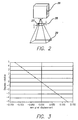
- FIG. 3 is a graphical illustration of the amount of pixel displacement obtainable from rotation of one embodiment of a sub-pixel image displacement device;
- FIG. 4 is a flow diagram of the processing of data and the pixel illumination process employed to create a three-dimensional object using a digital light projector; and
- FIGS. 5A-C are illustrating the illumination of full pixels in successive exposures within the boundary of a cross-section on a solidifiable liquid medium with no pixel shift and an additional exposure with a shift of ½ pixel in the X and Y directions.
- Flexible transport solid imaging of the type disclosed herein involves the layer-by-layer build-up of articles from a visible or UV liquid photopolymer material that is delivered by a flexible transport endless belt or reciprocatable sheet of film. Liquid photopolymer material is applied to the endless belt or reciprocatable sheet of film from a cartridge employing a gravure wheel that picks up the photopolymer and transfers it to the flexible transport device to provide fresh material to create new layers as the object is built. The photopolymer is imaged by radiation projected from either a digital UV projector or a digital visible light projector. The projector includes spatial light modulator, such as a digital micro-mirror device ("DMD"), that selectively illuminates pixels for imaging. Visible light projection is a preferred approach.
- Solid imaged parts are preferably built on an elevator platform that moves the build object or part up into contact with the liquid photopolymer and, after exposure, down and out of contact with the liquid photopolymer as successive layers or laminae are formed during the building process. The build object can be built on structures known as supports rather than directly on the elevator platform. Supports are used for more complex three-dimensional objects being built that have unsupported or partially unsupported surfaces.
- Commercially available digital light projectors, optionally modified to have a shorter focal length, may be employed, such as those available from InFocus Corporation of Wilsonville, Oregon and BenQ America Corp. of Irvine, CA. However, digital light projectors inherently have limited resolution. For example, if a 1024 by 768 pixel image is projected over a 10.24 inch by 7.68 inch (about 26 x 19.5 cm) area the effective resolution is 100 dpi (100 dots per inch or 40 dots per cm). In this case the minimum feature size is 0.010 inch (about 0.25 mm), part features may be located as far off their correct position as 0.005 inch (about 0.13 mm), and a wall drawn at 45° to the X or Y axis will have a peak to peak roughness of 0.007 inch (about 0.18 mm). Also, walls along the X and Y axes will exhibit roughness.
- Sub-pixel image shifting is a way to improve accuracy and edge smoothness in three-dimensional objects crated by solid imaging. This approach is based on exposing a full sized image, and then shifting the image plane half a pixel or less, adjusting the projected image to match the new image position, and then exposing again. With this technique, and shifting half a pixel in the X and Y planes, the 10.24 inch by 7.68 inch (about 26 x 19.5 cm) area described above would look like it had an effective resolution of 200 dpi (about 80 dots per cm). If the image is shifted twice at one third of a pixel, and exposed three times, it has an effective resolution of 300 dpi (about 120 dots per cm), etc. In these cases the accuracy and the wall smoothness of the solid image or three-dimensional object built are improved.
- In one application of the present invention, the photopolymer material is delivered to the imaging area via a transparent flexible transport film such as polypropylene or polycarbonate. The photopolymer is applied in a thin layer to the flexible transport film in the embodiment shown in FIG. 1.
- As seen in FIG. 1, a flexible transport imaging system indicated generally by the numeral 10, has a transparent transport means in the form of an
endless belt 11 that is positioned about a drivingroller 12 and afollower roller 14. A digital light projector is thelight source 15 that projects an image with selected pixels for illumination onto a mirror (not shown) below the upper run ofendless belt 11 in the exposure of a cross-section of a three-dimensional object 25 being formed on asupport platform 16.Support platform 16 is raised and lowered to bring the cross-sectional layers being formed into contact with the layer ofbuild material 24 that is deposited onendless belt 11 from the resin or solidifiable liquid medium cartridge indicated generally by the numeral 18.Cartridge 18 includes a resin reservoir of solidifiable liquid medium 20 and agravure roller 19 that applies the solidifiable liquid medium to belt 11. Atransparent backing plate 22 can be employed. A sub-pixel image placement device, indicated generally by the numeral 21, is placed between thelight source 15 and the target area on thebelt 11 that is coated with the solidifiableliquid medium 24. The exposure of the image cross-section by illuminating selected pixels creates a solidified portion of the cross-section of the three-dimensional object being formed.Device 21 alternatively can be a mirror with the pixel shifting device being located outside of the runs of theendless belt 21 or it could combine both the mirror and the pixel shifting device in a single element. - Looking now at FIG. 2, there is shown in a diagrammatic illustration of one embodiment of a pixel image displacement device that can be employed in a solid imaging system to create solid objects by successively creating thin layers of a solidified material one on top of the other by use of a digital light projector light to selectively illuminate pixels on the surface of a solidifiable liquid medium. FIG. 2 shows a digital
light projector 26 projecting an image through atransparent plate 28 rotatable about a fixedpoint 27 onto theimage plane 29 on the surface of a solidifiable liquid medium to form a cross-section of a three-dimensional object. Theplate 28 can be a glass plate that is mounted on a two axis mirror mount to displace by a fraction of a pixel the pixels in a projection of a full image of the cross-section of a three-dimensional object. Theplate 28 is moved through a tilt angle Θ that determines the amount of pixel displacement. In this embodiment, by way of example, the relationship between the tilt angle (Θ) of the glass plate and the displacement in the image plane (d) is given by the equation:
where I is the thickness of the glass and n is the index of refraction. - FIG. 3 gives a graphical illustration showing this displacement for the case of n = 1.5 and I = 4.35 mm. A tilt angle of 5° corresponds to a shift of ½ pixel for a 4 pixels per mm image.
- FIG. 4 shows the flow diagram of the process employed to create a three-dimensional object using the process and apparatus of the present invention.
- Data is sent to the solid imaging system from a CAD station (not shown) that converts the CAD data to a suitable digital layer data format and feeds it to a computer control system (also not shown) where the object data is manipulated to optimize the data via an algorithm to provide on/off instructions for the digital light projector. The solid imaging layer data is attained by the CAD data being processed by a slicing program to create cross-sectional data. The algorithm is then applied to the cross-sectional data by a suitable controller, such as a microprocessor or computer, to create the instructions for the digital light projector to illuminate selected pixels in the image within the boundary of the three-dimensional object in the cross-section being formed. The algorithm can select pixels for illumination that are only full pixels within the boundary of the image in the cross-section being exposed as seen in FIGS. 5A-C. FIG. 5A illustrates a first exposure of a cross-sectional layer. FIG. 5B illustrates a second exposure of the same cross-sectional layer with the pixels shifted in the X and y directions. FIG. 5C is the resultant exposure on the same cross-sectional layer of the two exposures illustrated in FIGS. 5A and 5B. Alternatively as desired, the algorithm can select as pixels for illumination only those pixels having a desired percentage, ranging from about 1% to about 100%, of the full pixel within the boundary of the image in the cross-section being exposed depending upon the number of exposures and pixel shifts to be done within each cross-section. For example, if only two exposures and hence only one pixel shift is to be done in each cross-section, it is desirable to illuminate only those pixels that have a lower percentage of the full pixel within the boundary of the image in the cross-section being exposed to increase the covered area, the resolution and edge smoothness of the image. Contrarily, if a higher number of exposures, such as 5 and hence 4 pixel shifts, is to be done in each cross-section, then illumination of only those pixels having a higher percentage of the full pixel within the boundary of the image would occur. Additionally, the algorithm may factor in the area of the pixel within the boundary of the image in the cross-section separately or in combination with a selected angle that the image boundary goes through the pixels within the image in the cross-section being exposed. At some desired percentage of pixels within the boundary of the cross-section being exposed, the image will be larger than desired. In this instance some "line width correction" of the cross-section's boundary will be required. Where supports are used in the build process, either with two separate materials or one material that is the same for the build object and the supports, no pixel shifting or second exposure in each support cross-section is utilized in a second support generating algorithm and any pixel having any portion of a support within the boundary of the image is illuminated.
- As seen in Figure 4, the cross-sectional data, including boundary and fill data for the object, is converted to pixel data and then processed to determine which selected pixels are to be illuminated as they fall within the boundary of the image in the cross-section be exposed. After the first exposure, the cross-sectional data is displaced by the desired sub-pixel distance and the cross-section is again illuminated with selected pixels. If the cross-section is full imaged, the process then returns to receive cross-sectional data from the next cross-section and the process is continued until a three-dimensional object is completed. Alternatively, if the cross-section is not full imaged, the cross-sectional data is displaced and selected pixels are illuminated in a process that continues until the cross-section is full imaged.
- As previously stated, either an ultraviolet ("UV') digital radiation projector or a visible digital light projector system may be used to cure the photocurable solidifiable liquid medium. With either type of a digital light projector, an algorithm that selects out pixels in a cross-section that have previously been exposed can be employed to prevent overcuring of the resin in those areas. Such overcuring can cause part curl, shrinkage and part distortion. Additionally, it is possible to convert the image boundaries to a bit map and then shift only those pixels that contain the boundaries to obtain the required sub-pixel placement accuracy edge smoothness.
- Any suitable fluid medium capable of solidification in response to the application of an appropriate form of energy stimulation may be employed in the practice of the present invention. Many liquid state chemicals are known which can be induced to change to solid state polymer plastic by irradiation with UV radiation or visible light. A suitable visible light curable photopolymer that may be employed in the practice of the present invention is shown in Table I below. This formulation exhibited excellent resolution and photospeed when utilized with a BenQ PB7220 projector. The parts created displayed outstanding green strength with balanced stiffness and toughness.
Table-1 Units of Weight Weight Percent Acrylate-24 (from Sartomer Company) % PRO 6817 (from Sartomer Company) 4.8 23.02 SR 833S (from Sartomer Company) 3.5 16.79 Ebecryl 83 (from UCB Chemicals Corp.) 2.4 11.51 PRO 6169 (from Sartomer Company) 5.2 24.94 SR 531 (from Sartomer Company) 3.6 17.27 lrgacure 1-907 (From Ciba Specialty Chemicals, Inc.) 0.75 3.60 Irgacure I-819 (From Ciba Specialty Chemicals, Inc.) 0.6 2.88 Total 20.85 100.00 - Alternatively, the image projected onto the solidifiable liquid medium for solid imaging an object can be shifted by rotating or otherwise moving the image shifting mirror or by physically moving the cross-section being built.
- While the invention has been described above with references to specific embodiments thereof, it is apparent that many changes, modifications and variations in the materials, arrangements of parts and steps can be made without departing from the inventive concept disclosed herein. For example, the sub-pixel image displacement technique could equally well be employed in a modified stereolithography apparatus having a vat employing a UV or visible digital light projector in place of a laser. An example of such a stereolithography apparatus that could easily be modified is a Viper si2™ SLA® system available commercially from 3D Systems, Inc., the applicant of the present invention. The sub-pixel image displacement device employs at least one rotatable transparent plate as described herein, rotatable mirrors, shiftable digital light projectors or a shiftable support platform to displace the pixels in the image of a projected cross-section of a three-dimensional object being formed from a solidifiable liquid medium. The liquid medium forms a fresh layer to be solidified either by a deep dip technique or by use of a recoater that places a fresh layer of liquid material onto an already exposed and solidified cross-section of the three-dimensional object being formed, as described in
U.S. Patent Nos. 5,902,537 and6,048,487 both assigned to the applicant to the present invention. Accordingly, the scope of the appended claims are intended to embrace all such changes, modifications and variations that may occur to one of skill in the art upon a reading of the disclosure.
Claims (19)
- An apparatus for forming a three-dimensional object layer-by-layer by solid imaging comprising:a. a frame;b. transparent transport means (11) moveably mounted to the frame;c. a radiation source (15) mounted to the frame for projecting a full image one cross-section at a time of a three-dimensional object to be built through the transparent transport means (11);d. a source (20) of solidifiable liquid medium in fluid flow communication with the transparent transport means (11) effective to apply the solidifiable liquid medium to the transparent transport means (11);e. a support platform (16) moveably mounted to the frame to support the three-dimensional object as it is built layer-by-layer;f. control means mounted to the frame effective to control movement of the transparent transport means (11) and the support platform (16) and to control illumination of selected pixels by the radiation source in an image exposure of a cross-section of the three-dimensional object on the solidifiable liquid medium;g. processing means in data flow communication with the control means to receive CAD data and convert the CAD data into sliced data representative of cross-sections of the three-dimensional object; andh. a sub-pixel image placement device (21) connected to the frame effective to move a projected image of the three-dimensional object in at least one additional exposure of a previously exposed cross-section of the three-dimensional image to obtain a high resolution image and a three-dimensional object that has all features properly positioned and smooth edges.
- The apparatus according to claim 1, in which the radiation source (15) comprises a UV radiation source or a visible light source.
- The apparatus according to claim 1 or claim 2, in which the radiation source (15) is a digital light projector.
- The apparatus according to any one of the preceding claims, in which the transparent transport means (11) is an endless belt, a flexible film or a plate.
- The apparatus according to any one of the preceding claims, in which the control means is a microprocessor that selects pixels to be illuminated in the exposure of a cross-section of the three-dimensional object on the solidifiable liquid by use of an algorithm.
- The apparatus according to claim 5, in which the microprocessor uses an algorithm to select pixels for illumination so that only those pixels are illuminated that have a full pixel within a boundary of the image in the cross-section being exposed.
- The apparatus according to claim 5, in which the microprocessor uses an algorithm to select pixels for illumination so that only those pixels are illuminated that have a desired percentage of the full pixel within a boundary of the image in the cross-section being exposed.
- The apparatus according to claim 7, in which the algorithm including a selected angle at which the boundary of the image passes through a pixel in a selection process of pixels to be illuminated in the cross-section being exposed.
- The apparatus according to claim 5, in which the microprocessor uses an algorithm to select pixels for illumination so that only those pixels are illuminated that have the boundary of the image pass therethrough at a selected angle in the cross-section being exposed.
- The apparatus according to claim 5, in which the microprocessor uses an algorithm to select out pixels for non-illumination so that only those pixels are illuminated in a subsequent illumination that have not previously been illuminated in the cross-section being exposed.
- The apparatus according to any one of the preceding claims, in which the sub-pixel image displacement device comprises a rotatable transparent plate positioned between the radiation source (15) and the transparent transport (11) means effective to displace the data representative of a cross-section through an angle in one of an X- or Y-plane to shift the cross-sectional image data equally.
- The apparatus according to claim 11, in which the transparent transport means (11) including a layer of the solidifiable liquid medium so that the rotatable transparent plate positioned between the radiation source (15) and the layer of solidifiable liquid medium is effective to displace the data representative of a cross-section through an angle in one of an X- or Y-plane to shift the cross-sectional image data equally on the layer of solidifiable liquid medium.
- The apparatus according to any one of claims 1 to 10, in which the sub-pixel image displacement device comprises a rotatable transparent plate positioned between the radiation source (15) and the transparent transport means (11) effective to move independently through an angle in the X-plane and the Y-plane to shift cross-sectional image data equally.
- The apparatus according to claim 13, in which the transparent transport means (11) including a layer of the solidifiable liquid medium so that the rotatable transparent plate positioned between the radiation source and the layer of solidifiable liquid medium is effective to move independently through an angle in the X-plane and the Y-plane to shift cross-sectional image data equally.
- The apparatus according to any one of claims 1 to 10, in which the sub-pixel image displacement device comprises a first transparent plate rotatable in the X-plane and a second transparent plate rotatable in the Y-plane positioned between the radiation source and the transparent transport means.
- The apparatus according to any one of claims 1 to 10, in which the sub-pixel image displacement device comprises means to move the radiation source (15) a fraction of a pixel.
- The apparatus according to any one of claims 1 to 10, in which the sub-pixel image displacement device comprises means to move the support platform (16) on which the three-dimensional object is being built a fraction of a pixel.
- The apparatus according to any one of claims 1 to 10, in which the sub-pixel image displacement device comprises mirrors positioned between the radiation source (15) and the transparent transport means (1) to move the image a fraction of a pixel.
- The apparatus according to any one of the preceding claims, further comprising a recoater (19) moveable mounted to the frame to recoat an exposed layer of the liquid medium with a fresh layer of the solidifiable liquid medium.
Applications Claiming Priority (1)
| Application Number | Priority Date | Filing Date | Title |
|---|---|---|---|
| US11/096,748 US7758799B2 (en) | 2005-04-01 | 2005-04-01 | Edge smoothness with low resolution projected images for use in solid imaging |
Publications (3)
| Publication Number | Publication Date |
|---|---|
| EP1733866A2 true EP1733866A2 (en) | 2006-12-20 |
| EP1733866A3 EP1733866A3 (en) | 2008-03-05 |
| EP1733866B1 EP1733866B1 (en) | 2010-01-20 |
Family
ID=36917381
Family Applications (3)
| Application Number | Title | Priority Date | Filing Date |
|---|---|---|---|
| EP06251473A Active EP1733866B1 (en) | 2005-04-01 | 2006-03-20 | Improved edge smoothness with low resolution projected images for use in 3D modeling |
| EP06251474A Active EP1710625B1 (en) | 2005-04-01 | 2006-03-20 | Improved edge smoothness with low resolution projected images for use in solid imaging |
| EP09174454.0A Active EP2148244B2 (en) | 2005-04-01 | 2006-03-20 | Improved Edge Smoothness with low resolution projected images for use in Solid Imaging |
Family Applications After (2)
| Application Number | Title | Priority Date | Filing Date |
|---|---|---|---|
| EP06251474A Active EP1710625B1 (en) | 2005-04-01 | 2006-03-20 | Improved edge smoothness with low resolution projected images for use in solid imaging |
| EP09174454.0A Active EP2148244B2 (en) | 2005-04-01 | 2006-03-20 | Improved Edge Smoothness with low resolution projected images for use in Solid Imaging |
Country Status (5)
| Country | Link |
|---|---|
| US (2) | US7758799B2 (en) |
| EP (3) | EP1733866B1 (en) |
| JP (2) | JP2006285262A (en) |
| AT (3) | ATE456074T1 (en) |
| DE (2) | DE602006011802D1 (en) |
Families Citing this family (55)
| Publication number | Priority date | Publication date | Assignee | Title |
|---|---|---|---|---|
| US20020014533A1 (en) * | 1995-12-18 | 2002-02-07 | Xiaxun Zhu | Automated object dimensioning system employing contour tracing, vertice detection, and forner point detection and reduction methods on 2-d range data maps |
| US6712856B1 (en) * | 2000-03-17 | 2004-03-30 | Kinamed, Inc. | Custom replacement device for resurfacing a femur and method of making the same |
| DE102004022606A1 (en) * | 2004-05-07 | 2005-12-15 | Envisiontec Gmbh | Method for producing a three-dimensional object with improved separation of hardened material layers from a building level |
| DE102004022961B4 (en) * | 2004-05-10 | 2008-11-20 | Envisiontec Gmbh | Method for producing a three-dimensional object with resolution improvement by means of pixel shift |
| DE502005004008D1 (en) | 2004-05-10 | 2008-06-19 | Envisiontec Gmbh | METHOD FOR PRODUCING A THREE-DIMENSIONAL OBJECT WITH RESOLUTION OF IMPROVEMENT BY PIXEL SHIFT |
| US7758799B2 (en) | 2005-04-01 | 2010-07-20 | 3D Systems, Inc. | Edge smoothness with low resolution projected images for use in solid imaging |
| DE102006019963B4 (en) | 2006-04-28 | 2023-12-07 | Envisiontec Gmbh | Device and method for producing a three-dimensional object by layer-by-layer solidifying a material that can be solidified under the influence of electromagnetic radiation using mask exposure |
| DE102006019964C5 (en) | 2006-04-28 | 2021-08-26 | Envisiontec Gmbh | Device and method for producing a three-dimensional object by means of mask exposure |
| US7467939B2 (en) * | 2006-05-03 | 2008-12-23 | 3D Systems, Inc. | Material delivery tension and tracking system for use in solid imaging |
| US7636610B2 (en) * | 2006-07-19 | 2009-12-22 | Envisiontec Gmbh | Method and device for producing a three-dimensional object, and computer and data carrier useful therefor |
| US9415544B2 (en) * | 2006-08-29 | 2016-08-16 | 3D Systems, Inc. | Wall smoothness, feature accuracy and resolution in projected images via exposure levels in solid imaging |
| JP2008085503A (en) * | 2006-09-26 | 2008-04-10 | Toshiba Corp | Three-dimensional image processing apparatus, method and program, and three-dimensional image display device |
| US7892474B2 (en) | 2006-11-15 | 2011-02-22 | Envisiontec Gmbh | Continuous generative process for producing a three-dimensional object |
| US8003039B2 (en) | 2007-01-17 | 2011-08-23 | 3D Systems, Inc. | Method for tilting solid image build platform for reducing air entrainment and for build release |
| US20080226346A1 (en) * | 2007-01-17 | 2008-09-18 | 3D Systems, Inc. | Inkjet Solid Imaging System and Method for Solid Imaging |
| US7771183B2 (en) * | 2007-01-17 | 2010-08-10 | 3D Systems, Inc. | Solid imaging system with removal of excess uncured build material |
| US20080181977A1 (en) * | 2007-01-17 | 2008-07-31 | Sperry Charles R | Brush assembly for removal of excess uncured build material |
| US7731887B2 (en) * | 2007-01-17 | 2010-06-08 | 3D Systems, Inc. | Method for removing excess uncured build material in solid imaging |
| US7614866B2 (en) | 2007-01-17 | 2009-11-10 | 3D Systems, Inc. | Solid imaging apparatus and method |
| US20080170112A1 (en) * | 2007-01-17 | 2008-07-17 | Hull Charles W | Build pad, solid image build, and method for building build supports |
| US8221671B2 (en) * | 2007-01-17 | 2012-07-17 | 3D Systems, Inc. | Imager and method for consistent repeatable alignment in a solid imaging apparatus |
| US7706910B2 (en) * | 2007-01-17 | 2010-04-27 | 3D Systems, Inc. | Imager assembly and method for solid imaging |
| US8105066B2 (en) | 2007-01-17 | 2012-01-31 | 3D Systems, Inc. | Cartridge for solid imaging apparatus and method |
| KR100817101B1 (en) * | 2007-04-04 | 2008-03-26 | 한국과학기술원 | Polymer or resist pattern, and mold, metal film pattern, metal pattern using thereof, and methods of forming the sames |
| DK2011631T3 (en) | 2007-07-04 | 2012-06-25 | Envisiontec Gmbh | Method and apparatus for making a three-dimensional object |
| EP2052693B2 (en) | 2007-10-26 | 2021-02-17 | Envisiontec GmbH | Process and freeform fabrication system for producing a three-dimensional object |
| US8048359B2 (en) | 2008-10-20 | 2011-11-01 | 3D Systems, Inc. | Compensation of actinic radiation intensity profiles for three-dimensional modelers |
| US8666142B2 (en) * | 2008-11-18 | 2014-03-04 | Global Filtration Systems | System and method for manufacturing |
| US8777602B2 (en) | 2008-12-22 | 2014-07-15 | Nederlandse Organisatie Voor Tobgepast-Natuurwetenschappelijk Onderzoek TNO | Method and apparatus for layerwise production of a 3D object |
| US8678805B2 (en) | 2008-12-22 | 2014-03-25 | Dsm Ip Assets Bv | System and method for layerwise production of a tangible object |
| BRPI0923627A2 (en) | 2008-12-22 | 2016-01-19 | Nl Organisate Voor Toegepast Natuurwetenchappelijk Onderzoek Tno | method and system for layered production of a tangible object |
| US8372330B2 (en) * | 2009-10-19 | 2013-02-12 | Global Filtration Systems | Resin solidification substrate and assembly |
| KR101995185B1 (en) | 2009-12-17 | 2019-07-01 | 디에스엠 아이피 어셋츠 비.브이. | Liquid radiation curable resins for additive fabrication comprising a triaryl sulfonium borate cationic photoinitiator |
| JP5617603B2 (en) | 2010-12-21 | 2014-11-05 | ソニー株式会社 | Display control apparatus, display control method, and program |
| JP5652652B2 (en) * | 2010-12-27 | 2015-01-14 | ソニー株式会社 | Display control apparatus and method |
| US9862146B2 (en) | 2011-06-15 | 2018-01-09 | Dsm Ip Assets B.V. | Substrate-based additive fabrication process and apparatus |
| US8691476B2 (en) | 2011-12-16 | 2014-04-08 | Taiwan Semiconductor Manufacturing Company, Ltd. | EUV mask and method for forming the same |
| US9034237B2 (en) | 2012-09-25 | 2015-05-19 | 3D Systems, Inc. | Solid imaging systems, components thereof, and methods of solid imaging |
| CN105209972B (en) * | 2013-03-14 | 2017-06-27 | 斯特塔西有限公司 | Enhancing resolution ratio DLP projector equipment and its application method |
| TWI618640B (en) * | 2013-09-13 | 2018-03-21 | Silicon Touch Technology Inc. | Three dimensional printing system, and method for three dimensional printing |
| US9527244B2 (en) | 2014-02-10 | 2016-12-27 | Global Filtration Systems | Apparatus and method for forming three-dimensional objects from solidifiable paste |
| CN104015363B (en) * | 2014-06-20 | 2016-08-24 | 大族激光科技产业集团股份有限公司 | The DLP rapid prototyping system of a kind of large scale object and method |
| FR3027554B1 (en) * | 2014-10-27 | 2020-02-07 | Centre National De La Recherche Scientifique | THREE-DIMENSIONAL PRINTING PROCESS |
| TWI628208B (en) * | 2015-01-12 | 2018-07-01 | 國立台灣科技大學 | Method of stereolithography fabrication and photo-curing photosensitive resin |
| CN104820345B (en) * | 2015-05-23 | 2017-03-22 | 南昌航空大学 | Method for improving digital photoetching resolution on basis of sub-pixel modulation |
| CN108025503B (en) * | 2015-10-30 | 2021-10-26 | 惠普发展公司,有限责任合伙企业 | Generating parametric descriptions of three-dimensional objects |
| CN105666885A (en) * | 2016-04-18 | 2016-06-15 | 周宏志 | Partitioned photocuring 3D printing forming method, system and device based on DLP |
| CN105904727A (en) * | 2016-04-19 | 2016-08-31 | 周宏志 | DLP-based photocuring 3D printing forming method, system and device |
| US10821717B2 (en) | 2016-07-22 | 2020-11-03 | General Electric Company | Layer orientation control for pixel-based additive manufacturing |
| US10737479B2 (en) | 2017-01-12 | 2020-08-11 | Global Filtration Systems | Method of making three-dimensional objects using both continuous and discontinuous solidification |
| US20190129308A1 (en) | 2017-11-02 | 2019-05-02 | Taiwan Green Point Enterprises Co., Ltd. | Digital masking system, pattern imaging apparatus and digital masking method |
| US11872760B2 (en) * | 2020-10-29 | 2024-01-16 | Seurat Technologies, Inc. | Distributed flux array |
| US11731367B2 (en) | 2021-06-23 | 2023-08-22 | General Electric Company | Drive system for additive manufacturing |
| US11826950B2 (en) | 2021-07-09 | 2023-11-28 | General Electric Company | Resin management system for additive manufacturing |
| US11813799B2 (en) | 2021-09-01 | 2023-11-14 | General Electric Company | Control systems and methods for additive manufacturing |
Citations (2)
| Publication number | Priority date | Publication date | Assignee | Title |
|---|---|---|---|---|
| US5902537A (en) | 1995-02-01 | 1999-05-11 | 3D Systems, Inc. | Rapid recoating of three-dimensional objects formed on a cross-sectional basis |
| US6048487A (en) | 1988-09-26 | 2000-04-11 | 3D Systems, Inc. | Recoating stereolithographic layers |
Family Cites Families (62)
| Publication number | Priority date | Publication date | Assignee | Title |
|---|---|---|---|---|
| GB1301277A (en) | 1969-02-21 | 1972-12-29 | ||
| US4752498A (en) * | 1987-03-02 | 1988-06-21 | Fudim Efrem V | Method and apparatus for production of three-dimensional objects by photosolidification |
| JPH0698685B2 (en) * | 1987-06-12 | 1994-12-07 | 松下電器産業株式会社 | Optical modeling device |
| US4851656A (en) † | 1988-01-11 | 1989-07-25 | The Gerber Scientific Instrument Company | Method and apparatus for enhancing optical photoplotter accuracy |
| US5130064A (en) * | 1988-04-18 | 1992-07-14 | 3D Systems, Inc. | Method of making a three dimensional object by stereolithography |
| US5184307A (en) * | 1988-04-18 | 1993-02-02 | 3D Systems, Inc. | Method and apparatus for production of high resolution three-dimensional objects by stereolithography |
| US5523193A (en) * | 1988-05-31 | 1996-06-04 | Texas Instruments Incorporated | Method and apparatus for patterning and imaging member |
| US5009585A (en) * | 1989-12-18 | 1991-04-23 | Mitsui Engineering & Shipbuilding Co., Ltd. | Optical molding apparatus and movable base device therefor |
| US5693144A (en) † | 1990-03-19 | 1997-12-02 | 3D Systems, Inc. | Vibrationally enhanced stereolithographic recoating |
| US5049901A (en) * | 1990-07-02 | 1991-09-17 | Creo Products Inc. | Light modulator using large area light sources |
| US5506607A (en) * | 1991-01-25 | 1996-04-09 | Sanders Prototypes Inc. | 3-D model maker |
| US5278949A (en) † | 1991-03-12 | 1994-01-11 | Hewlett-Packard Company | Polygon renderer which determines the coordinates of polygon edges to sub-pixel resolution in the X,Y and Z coordinates directions |
| NL9102165A (en) | 1991-12-23 | 1993-07-16 | Oce Nederland Bv | Apparatus for rasterizing image data in contour form. |
| US5247180A (en) | 1991-12-30 | 1993-09-21 | Texas Instruments Incorporated | Stereolithographic apparatus and method of use |
| JPH0784033B2 (en) * | 1992-02-20 | 1995-09-13 | 帝人製機株式会社 | Stereolithography apparatus and stereolithography method |
| FR2692053A1 (en) | 1992-06-05 | 1993-12-10 | Goreta Lucas | Model prodn. by selective photopolymerisation of liq. or powder - using active liq. crystal mask or active light source controlled by computer instead of controlled movement focused laser |
| US5510066A (en) * | 1992-08-14 | 1996-04-23 | Guild Associates, Inc. | Method for free-formation of a free-standing, three-dimensional body |
| US5454069A (en) * | 1992-08-25 | 1995-09-26 | University Of Kentucky Research Foundation | Process for converting serial image to the sterolithography apparatus (SLA) slice file with automatic base and support generation |
| JP2706611B2 (en) * | 1993-10-14 | 1998-01-28 | 帝人製機株式会社 | Stereolithography method and stereolithography device |
| JP3353980B2 (en) * | 1993-12-14 | 2002-12-09 | 帝人製機株式会社 | Stereolithography method and stereolithography device |
| JPH07236086A (en) † | 1994-02-23 | 1995-09-05 | Konica Corp | Picture input device |
| BE1008372A3 (en) * | 1994-04-19 | 1996-04-02 | Materialise Nv | METHOD FOR MANUFACTURING A perfected MEDICAL MODEL BASED ON DIGITAL IMAGE INFORMATION OF A BODY. |
| JPH08222510A (en) * | 1995-02-08 | 1996-08-30 | Sony Corp | Focusing mechanism of projection aligner |
| US6270335B2 (en) * | 1995-09-27 | 2001-08-07 | 3D Systems, Inc. | Selective deposition modeling method and apparatus for forming three-dimensional objects and supports |
| JP3617657B2 (en) * | 1995-11-13 | 2005-02-09 | 株式会社ニコン | Misalignment correction method |
| US5738817A (en) * | 1996-02-08 | 1998-04-14 | Rutgers, The State University | Solid freeform fabrication methods |
| US6312134B1 (en) | 1996-07-25 | 2001-11-06 | Anvik Corporation | Seamless, maskless lithography system using spatial light modulator |
| EP0914626A4 (en) | 1996-07-25 | 2002-02-20 | Anvik Corp | Seamless, maskless lithography system using spatial light modulator |
| US6051179A (en) * | 1997-03-19 | 2000-04-18 | Replicator Systems, Inc. | Apparatus and method for production of three-dimensional models by spatial light modulator |
| US6001297A (en) * | 1997-04-28 | 1999-12-14 | 3D Systems, Inc. | Method for controlling exposure of a solidfiable medium using a pulsed radiation source in building a three-dimensional object using stereolithography |
| US5945058A (en) * | 1997-05-13 | 1999-08-31 | 3D Systems, Inc. | Method and apparatus for identifying surface features associated with selected lamina of a three-dimensional object being stereolithographically formed |
| US5894036A (en) * | 1997-06-10 | 1999-04-13 | Tylko; Marek K. | Three-dimensional plotter |
| WO1999063385A1 (en) | 1998-06-04 | 1999-12-09 | Board Of Regents, The University Of Texas System | Digital optical chemistry micromirror imager |
| JP3068072B2 (en) * | 1998-11-25 | 2000-07-24 | 株式会社アフィット | Stereolithography method and stereolithography device |
| US6399010B1 (en) * | 1999-02-08 | 2002-06-04 | 3D Systems, Inc. | Method and apparatus for stereolithographically forming three dimensional objects with reduced distortion |
| US7068825B2 (en) * | 1999-03-08 | 2006-06-27 | Orametrix, Inc. | Scanning system and calibration method for capturing precise three-dimensional information of objects |
| DE19929199A1 (en) | 1999-06-25 | 2001-01-18 | Hap Handhabungs Automatisierun | Method and device for producing a three-dimensional object |
| DE19957370C2 (en) | 1999-11-29 | 2002-03-07 | Carl Johannes Fruth | Method and device for coating a substrate |
| US6547552B1 (en) † | 2000-02-08 | 2003-04-15 | Efrem V. Fudim | Fabrication of three-dimensional objects by irradiation of radiation-curable materials |
| US7318718B2 (en) * | 2000-06-06 | 2008-01-15 | Teijin Seiki Co., Ltd. | Stereolithographic apparatus and method for manufacturing three-dimensional object |
| JP3722204B2 (en) * | 2000-06-16 | 2005-11-30 | シャープ株式会社 | Projection-type image display device |
| JP2002021834A (en) | 2000-07-07 | 2002-01-23 | Sankyu Inc | Fastener |
| US6500378B1 (en) * | 2000-07-13 | 2002-12-31 | Eom Technologies, L.L.C. | Method and apparatus for creating three-dimensional objects by cross-sectional lithography |
| US6833234B1 (en) * | 2000-08-04 | 2004-12-21 | Massachusetts Institute Of Technology | Stereolithographic patterning with variable size exposure areas |
| US7088432B2 (en) * | 2000-09-27 | 2006-08-08 | The Regents Of The University Of California | Dynamic mask projection stereo micro lithography |
| DE10053742C5 (en) | 2000-10-30 | 2006-06-08 | Concept Laser Gmbh | Device for sintering, ablating and / or inscribing by means of electromagnetic radiation and method for operating the device |
| JP4552337B2 (en) * | 2000-12-28 | 2010-09-29 | 株式会社ニコン | Projection optical system manufacturing method and exposure apparatus manufacturing method |
| JP4828028B2 (en) † | 2001-01-23 | 2011-11-30 | ナブテスコ株式会社 | 3D modeling apparatus and 3D modeling method |
| US7154515B2 (en) | 2001-06-15 | 2006-12-26 | Perkinelmer, Inc. | Method and apparatus for reducing printing artifacts of stitched images |
| US6665048B2 (en) * | 2002-01-22 | 2003-12-16 | Creo Inc. | Method for imaging a continuously moving object |
| US6855482B2 (en) * | 2002-04-09 | 2005-02-15 | Day International, Inc. | Liquid transfer articles and method for producing the same using digital imaging photopolymerization |
| US6833231B2 (en) * | 2002-07-31 | 2004-12-21 | 3D Systems, Inc. | Toughened stereolithographic resin compositions |
| EP1573366B1 (en) * | 2002-08-24 | 2016-11-09 | Chime Ball Technology Co., Ltd. | Continuous direct-write optical lithography |
| JP2004200430A (en) * | 2002-12-19 | 2004-07-15 | Nikon Corp | Aligner, method of adjusting the same, and method of exposure |
| JP4417911B2 (en) | 2003-09-11 | 2010-02-17 | ナブテスコ株式会社 | Optical three-dimensional modeling method and apparatus |
| DE102004022606A1 (en) * | 2004-05-07 | 2005-12-15 | Envisiontec Gmbh | Method for producing a three-dimensional object with improved separation of hardened material layers from a building level |
| DE102004022961B4 (en) † | 2004-05-10 | 2008-11-20 | Envisiontec Gmbh | Method for producing a three-dimensional object with resolution improvement by means of pixel shift |
| DE502005004008D1 (en) | 2004-05-10 | 2008-06-19 | Envisiontec Gmbh | METHOD FOR PRODUCING A THREE-DIMENSIONAL OBJECT WITH RESOLUTION OF IMPROVEMENT BY PIXEL SHIFT |
| JP4525424B2 (en) | 2005-03-30 | 2010-08-18 | Jsr株式会社 | Stereolithography method |
| US7758799B2 (en) | 2005-04-01 | 2010-07-20 | 3D Systems, Inc. | Edge smoothness with low resolution projected images for use in solid imaging |
| DE102006019963B4 (en) | 2006-04-28 | 2023-12-07 | Envisiontec Gmbh | Device and method for producing a three-dimensional object by layer-by-layer solidifying a material that can be solidified under the influence of electromagnetic radiation using mask exposure |
| US7636610B2 (en) * | 2006-07-19 | 2009-12-22 | Envisiontec Gmbh | Method and device for producing a three-dimensional object, and computer and data carrier useful therefor |
-
2005
- 2005-04-01 US US11/096,748 patent/US7758799B2/en active Active
-
2006
- 2006-03-20 DE DE602006011802T patent/DE602006011802D1/en active Active
- 2006-03-20 AT AT06251474T patent/ATE456074T1/en not_active IP Right Cessation
- 2006-03-20 EP EP06251473A patent/EP1733866B1/en active Active
- 2006-03-20 AT AT06251473T patent/ATE456075T1/en not_active IP Right Cessation
- 2006-03-20 EP EP06251474A patent/EP1710625B1/en active Active
- 2006-03-20 EP EP09174454.0A patent/EP2148244B2/en active Active
- 2006-03-20 AT AT09174454T patent/ATE540334T1/en active
- 2006-03-20 DE DE602006011819T patent/DE602006011819D1/en active Active
- 2006-04-03 JP JP2006101789A patent/JP2006285262A/en not_active Withdrawn
- 2006-04-03 JP JP2006101783A patent/JP2006285261A/en active Pending
-
2010
- 2010-06-09 US US12/797,198 patent/US8703037B2/en active Active
Patent Citations (2)
| Publication number | Priority date | Publication date | Assignee | Title |
|---|---|---|---|---|
| US6048487A (en) | 1988-09-26 | 2000-04-11 | 3D Systems, Inc. | Recoating stereolithographic layers |
| US5902537A (en) | 1995-02-01 | 1999-05-11 | 3D Systems, Inc. | Rapid recoating of three-dimensional objects formed on a cross-sectional basis |
Also Published As
| Publication number | Publication date |
|---|---|
| EP2148244B1 (en) | 2012-01-04 |
| EP1733866A3 (en) | 2008-03-05 |
| EP1710625A3 (en) | 2008-03-05 |
| ATE540334T1 (en) | 2012-01-15 |
| US8703037B2 (en) | 2014-04-22 |
| ATE456075T1 (en) | 2010-02-15 |
| DE602006011802D1 (en) | 2010-03-11 |
| ATE456074T1 (en) | 2010-02-15 |
| US20060239588A1 (en) | 2006-10-26 |
| US7758799B2 (en) | 2010-07-20 |
| EP1710625B1 (en) | 2010-01-20 |
| JP2006285261A (en) | 2006-10-19 |
| EP1710625A2 (en) | 2006-10-11 |
| EP2148244B2 (en) | 2017-11-15 |
| JP2006285262A (en) | 2006-10-19 |
| EP2148244A1 (en) | 2010-01-27 |
| US20110207057A1 (en) | 2011-08-25 |
| DE602006011819D1 (en) | 2010-03-11 |
| EP1733866B1 (en) | 2010-01-20 |
Similar Documents
| Publication | Publication Date | Title |
|---|---|---|
| EP1733866B1 (en) | Improved edge smoothness with low resolution projected images for use in 3D modeling | |
| US20160332368A1 (en) | Wall Smoothness, Feature Accuracy and Resolution in Projected Images via Exposure Levels in Solid Imaging | |
| US7906061B2 (en) | Bubble-free cross-sections for use in solid imaging | |
| EP2186625B1 (en) | Method for manufacturing a three-dimensional object | |
| JP4787204B2 (en) | Material supply tension and tracking device for use in solid-state imaging | |
| US8326024B2 (en) | Method of reducing the force required to separate a solidified object from a substrate | |
| US20180029299A1 (en) | Additive manufacturing with offset stitching | |
| KR101798533B1 (en) | Molding apparatus and method by the 3d printer | |
| CN107303728A (en) | Use the 3 D-printing of the optimization of the supporter made |
Legal Events
| Date | Code | Title | Description |
|---|---|---|---|
| PUAI | Public reference made under article 153(3) epc to a published international application that has entered the european phase |
Free format text: ORIGINAL CODE: 0009012 |
|
| AK | Designated contracting states |
Kind code of ref document: A2 Designated state(s): AT BE BG CH CY CZ DE DK EE ES FI FR GB GR HU IE IS IT LI LT LU LV MC NL PL PT RO SE SI SK TR |
|
| AX | Request for extension of the european patent |
Extension state: AL BA HR MK YU |
|
| PUAL | Search report despatched |
Free format text: ORIGINAL CODE: 0009013 |
|
| AK | Designated contracting states |
Kind code of ref document: A3 Designated state(s): AT BE BG CH CY CZ DE DK EE ES FI FR GB GR HU IE IS IT LI LT LU LV MC NL PL PT RO SE SI SK TR |
|
| AX | Request for extension of the european patent |
Extension state: AL BA HR MK YU |
|
| RIC1 | Information provided on ipc code assigned before grant |
Ipc: B29C 67/00 20060101ALI20080125BHEP Ipc: G03F 7/20 20060101ALI20080125BHEP Ipc: G03F 7/00 20060101AFI20080125BHEP |
|
| RAP1 | Party data changed (applicant data changed or rights of an application transferred) |
Owner name: 3D SYSTEMS, INC. |
|
| 17P | Request for examination filed |
Effective date: 20080905 |
|
| AKX | Designation fees paid |
Designated state(s): AT BE BG CH CY CZ DE DK EE ES FI FR GB GR HU IE IS IT LI LT LU LV MC NL PL PT RO SE SI SK TR |
|
| GRAP | Despatch of communication of intention to grant a patent |
Free format text: ORIGINAL CODE: EPIDOSNIGR1 |
|
| GRAS | Grant fee paid |
Free format text: ORIGINAL CODE: EPIDOSNIGR3 |
|
| GRAA | (expected) grant |
Free format text: ORIGINAL CODE: 0009210 |
|
| AK | Designated contracting states |
Kind code of ref document: B1 Designated state(s): AT BE BG CH CY CZ DE DK EE ES FI FR GB GR HU IE IS IT LI LT LU LV MC NL PL PT RO SE SI SK TR |
|
| REG | Reference to a national code |
Ref country code: GB Ref legal event code: FG4D |
|
| REG | Reference to a national code |
Ref country code: CH Ref legal event code: EP |
|
| REG | Reference to a national code |
Ref country code: IE Ref legal event code: FG4D |
|
| REF | Corresponds to: |
Ref document number: 602006011819 Country of ref document: DE Date of ref document: 20100311 Kind code of ref document: P |
|
| REG | Reference to a national code |
Ref country code: NL Ref legal event code: VDEP Effective date: 20100120 |
|
| LTIE | Lt: invalidation of european patent or patent extension |
Effective date: 20100120 |
|
| PG25 | Lapsed in a contracting state [announced via postgrant information from national office to epo] |
Ref country code: AT Free format text: LAPSE BECAUSE OF FAILURE TO SUBMIT A TRANSLATION OF THE DESCRIPTION OR TO PAY THE FEE WITHIN THE PRESCRIBED TIME-LIMIT Effective date: 20100120 |
|
| PG25 | Lapsed in a contracting state [announced via postgrant information from national office to epo] |
Ref country code: LT Free format text: LAPSE BECAUSE OF FAILURE TO SUBMIT A TRANSLATION OF THE DESCRIPTION OR TO PAY THE FEE WITHIN THE PRESCRIBED TIME-LIMIT Effective date: 20100120 Ref country code: ES Free format text: LAPSE BECAUSE OF FAILURE TO SUBMIT A TRANSLATION OF THE DESCRIPTION OR TO PAY THE FEE WITHIN THE PRESCRIBED TIME-LIMIT Effective date: 20100501 Ref country code: NL Free format text: LAPSE BECAUSE OF FAILURE TO SUBMIT A TRANSLATION OF THE DESCRIPTION OR TO PAY THE FEE WITHIN THE PRESCRIBED TIME-LIMIT Effective date: 20100120 Ref country code: PT Free format text: LAPSE BECAUSE OF FAILURE TO SUBMIT A TRANSLATION OF THE DESCRIPTION OR TO PAY THE FEE WITHIN THE PRESCRIBED TIME-LIMIT Effective date: 20100520 Ref country code: IS Free format text: LAPSE BECAUSE OF FAILURE TO SUBMIT A TRANSLATION OF THE DESCRIPTION OR TO PAY THE FEE WITHIN THE PRESCRIBED TIME-LIMIT Effective date: 20100520 |
|
| PG25 | Lapsed in a contracting state [announced via postgrant information from national office to epo] |
Ref country code: LV Free format text: LAPSE BECAUSE OF FAILURE TO SUBMIT A TRANSLATION OF THE DESCRIPTION OR TO PAY THE FEE WITHIN THE PRESCRIBED TIME-LIMIT Effective date: 20100120 Ref country code: PL Free format text: LAPSE BECAUSE OF FAILURE TO SUBMIT A TRANSLATION OF THE DESCRIPTION OR TO PAY THE FEE WITHIN THE PRESCRIBED TIME-LIMIT Effective date: 20100120 Ref country code: SI Free format text: LAPSE BECAUSE OF FAILURE TO SUBMIT A TRANSLATION OF THE DESCRIPTION OR TO PAY THE FEE WITHIN THE PRESCRIBED TIME-LIMIT Effective date: 20100120 Ref country code: FI Free format text: LAPSE BECAUSE OF FAILURE TO SUBMIT A TRANSLATION OF THE DESCRIPTION OR TO PAY THE FEE WITHIN THE PRESCRIBED TIME-LIMIT Effective date: 20100120 |
|
| PG25 | Lapsed in a contracting state [announced via postgrant information from national office to epo] |
Ref country code: RO Free format text: LAPSE BECAUSE OF FAILURE TO SUBMIT A TRANSLATION OF THE DESCRIPTION OR TO PAY THE FEE WITHIN THE PRESCRIBED TIME-LIMIT Effective date: 20100120 Ref country code: MC Free format text: LAPSE BECAUSE OF NON-PAYMENT OF DUE FEES Effective date: 20100331 Ref country code: GR Free format text: LAPSE BECAUSE OF FAILURE TO SUBMIT A TRANSLATION OF THE DESCRIPTION OR TO PAY THE FEE WITHIN THE PRESCRIBED TIME-LIMIT Effective date: 20100421 Ref country code: EE Free format text: LAPSE BECAUSE OF FAILURE TO SUBMIT A TRANSLATION OF THE DESCRIPTION OR TO PAY THE FEE WITHIN THE PRESCRIBED TIME-LIMIT Effective date: 20100120 Ref country code: CY Free format text: LAPSE BECAUSE OF FAILURE TO SUBMIT A TRANSLATION OF THE DESCRIPTION OR TO PAY THE FEE WITHIN THE PRESCRIBED TIME-LIMIT Effective date: 20100120 Ref country code: BE Free format text: LAPSE BECAUSE OF FAILURE TO SUBMIT A TRANSLATION OF THE DESCRIPTION OR TO PAY THE FEE WITHIN THE PRESCRIBED TIME-LIMIT Effective date: 20100120 Ref country code: SE Free format text: LAPSE BECAUSE OF FAILURE TO SUBMIT A TRANSLATION OF THE DESCRIPTION OR TO PAY THE FEE WITHIN THE PRESCRIBED TIME-LIMIT Effective date: 20100120 |
|
| REG | Reference to a national code |
Ref country code: CH Ref legal event code: PL |
|
| PLBE | No opposition filed within time limit |
Free format text: ORIGINAL CODE: 0009261 |
|
| STAA | Information on the status of an ep patent application or granted ep patent |
Free format text: STATUS: NO OPPOSITION FILED WITHIN TIME LIMIT |
|
| PG25 | Lapsed in a contracting state [announced via postgrant information from national office to epo] |
Ref country code: CZ Free format text: LAPSE BECAUSE OF FAILURE TO SUBMIT A TRANSLATION OF THE DESCRIPTION OR TO PAY THE FEE WITHIN THE PRESCRIBED TIME-LIMIT Effective date: 20100120 Ref country code: SK Free format text: LAPSE BECAUSE OF FAILURE TO SUBMIT A TRANSLATION OF THE DESCRIPTION OR TO PAY THE FEE WITHIN THE PRESCRIBED TIME-LIMIT Effective date: 20100120 Ref country code: BG Free format text: LAPSE BECAUSE OF FAILURE TO SUBMIT A TRANSLATION OF THE DESCRIPTION OR TO PAY THE FEE WITHIN THE PRESCRIBED TIME-LIMIT Effective date: 20100420 |
|
| 26N | No opposition filed |
Effective date: 20101021 |
|
| PG25 | Lapsed in a contracting state [announced via postgrant information from national office to epo] |
Ref country code: IE Free format text: LAPSE BECAUSE OF NON-PAYMENT OF DUE FEES Effective date: 20100320 Ref country code: DK Free format text: LAPSE BECAUSE OF FAILURE TO SUBMIT A TRANSLATION OF THE DESCRIPTION OR TO PAY THE FEE WITHIN THE PRESCRIBED TIME-LIMIT Effective date: 20100120 |
|
| PG25 | Lapsed in a contracting state [announced via postgrant information from national office to epo] |
Ref country code: LI Free format text: LAPSE BECAUSE OF NON-PAYMENT OF DUE FEES Effective date: 20100331 Ref country code: CH Free format text: LAPSE BECAUSE OF NON-PAYMENT OF DUE FEES Effective date: 20100331 |
|
| PG25 | Lapsed in a contracting state [announced via postgrant information from national office to epo] |
Ref country code: LU Free format text: LAPSE BECAUSE OF NON-PAYMENT OF DUE FEES Effective date: 20100320 Ref country code: HU Free format text: LAPSE BECAUSE OF FAILURE TO SUBMIT A TRANSLATION OF THE DESCRIPTION OR TO PAY THE FEE WITHIN THE PRESCRIBED TIME-LIMIT Effective date: 20100721 |
|
| PG25 | Lapsed in a contracting state [announced via postgrant information from national office to epo] |
Ref country code: TR Free format text: LAPSE BECAUSE OF FAILURE TO SUBMIT A TRANSLATION OF THE DESCRIPTION OR TO PAY THE FEE WITHIN THE PRESCRIBED TIME-LIMIT Effective date: 20100120 |
|
| REG | Reference to a national code |
Ref country code: FR Ref legal event code: PLFP Year of fee payment: 11 |
|
| REG | Reference to a national code |
Ref country code: DE Ref legal event code: R079 Ref document number: 602006011819 Country of ref document: DE Free format text: PREVIOUS MAIN CLASS: B29C0067000000 Ipc: B29C0064106000 |
|
| REG | Reference to a national code |
Ref country code: FR Ref legal event code: PLFP Year of fee payment: 12 |
|
| REG | Reference to a national code |
Ref country code: FR Ref legal event code: PLFP Year of fee payment: 13 |
|
| PGFP | Annual fee paid to national office [announced via postgrant information from national office to epo] |
Ref country code: FR Payment date: 20230327 Year of fee payment: 18 |
|
| PGFP | Annual fee paid to national office [announced via postgrant information from national office to epo] |
Ref country code: IT Payment date: 20230321 Year of fee payment: 18 Ref country code: GB Payment date: 20230327 Year of fee payment: 18 Ref country code: DE Payment date: 20230329 Year of fee payment: 18 |