EP1728526B1 - System for monitoring the pressure in a blood line and a device to be used with such a system - Google Patents
System for monitoring the pressure in a blood line and a device to be used with such a system Download PDFInfo
- Publication number
- EP1728526B1 EP1728526B1 EP05011997A EP05011997A EP1728526B1 EP 1728526 B1 EP1728526 B1 EP 1728526B1 EP 05011997 A EP05011997 A EP 05011997A EP 05011997 A EP05011997 A EP 05011997A EP 1728526 B1 EP1728526 B1 EP 1728526B1
- Authority
- EP
- European Patent Office
- Prior art keywords
- pressure transducer
- blood
- sensor
- section
- line
- Prior art date
- Legal status (The legal status is an assumption and is not a legal conclusion. Google has not performed a legal analysis and makes no representation as to the accuracy of the status listed.)
- Not-in-force
Links
Images

Classifications
-
- A—HUMAN NECESSITIES
- A61—MEDICAL OR VETERINARY SCIENCE; HYGIENE
- A61M—DEVICES FOR INTRODUCING MEDIA INTO, OR ONTO, THE BODY; DEVICES FOR TRANSDUCING BODY MEDIA OR FOR TAKING MEDIA FROM THE BODY; DEVICES FOR PRODUCING OR ENDING SLEEP OR STUPOR
- A61M1/00—Suction or pumping devices for medical purposes; Devices for carrying-off, for treatment of, or for carrying-over, body-liquids; Drainage systems
- A61M1/36—Other treatment of blood in a by-pass of the natural circulatory system, e.g. temperature adaptation, irradiation ; Extra-corporeal blood circuits
- A61M1/3621—Extra-corporeal blood circuits
- A61M1/3639—Blood pressure control, pressure transducers specially adapted therefor
- A61M1/3641—Pressure isolators
-
- A—HUMAN NECESSITIES
- A61—MEDICAL OR VETERINARY SCIENCE; HYGIENE
- A61M—DEVICES FOR INTRODUCING MEDIA INTO, OR ONTO, THE BODY; DEVICES FOR TRANSDUCING BODY MEDIA OR FOR TAKING MEDIA FROM THE BODY; DEVICES FOR PRODUCING OR ENDING SLEEP OR STUPOR
- A61M2205/00—General characteristics of the apparatus
- A61M2205/15—Detection of leaks
-
- A—HUMAN NECESSITIES
- A61—MEDICAL OR VETERINARY SCIENCE; HYGIENE
- A61M—DEVICES FOR INTRODUCING MEDIA INTO, OR ONTO, THE BODY; DEVICES FOR TRANSDUCING BODY MEDIA OR FOR TAKING MEDIA FROM THE BODY; DEVICES FOR PRODUCING OR ENDING SLEEP OR STUPOR
- A61M2205/00—General characteristics of the apparatus
- A61M2205/16—General characteristics of the apparatus with back-up system in case of failure
-
- A—HUMAN NECESSITIES
- A61—MEDICAL OR VETERINARY SCIENCE; HYGIENE
- A61M—DEVICES FOR INTRODUCING MEDIA INTO, OR ONTO, THE BODY; DEVICES FOR TRANSDUCING BODY MEDIA OR FOR TAKING MEDIA FROM THE BODY; DEVICES FOR PRODUCING OR ENDING SLEEP OR STUPOR
- A61M2205/00—General characteristics of the apparatus
- A61M2205/33—Controlling, regulating or measuring
- A61M2205/3306—Optical measuring means
- A61M2205/3313—Optical measuring means used specific wavelengths
Definitions
- the invention relates to the area of pressure monitoring devices for blood lines, eg. see EP 1547630 .
- blood is extracted from a patient, circulated in an extra-corporeal blood circuit that comprises a blood treatment unit, and infused back to the patient.
- blood treatments are procedures to be used in case of kidney failure like hemodialysis, hemofiltration or hemodiafiltration.
- examples for blood treatments comprise blood oxygenation, blood component separation by centrifuge or filter techniques, or the removal of blood components by adsorption.
- blood is continuously or quasi-continuously circulated in the blood lines of the extra-corporeal blood circuit.
- the pressure in the arterial blood line leading from the patient to the blood treatment unit and in the venous blood line leading from the blood treatment unit to the patient are continuously measured. In contemporary devices this is accomplished by pressure transducer lines branching off the arterial and the venous lines, respectively, and leading to pressure transducers that are part of the blood treatment device.
- a first pressure transducer protector filter is used that is dividing the pressure transducer line into a blood line section between the blood line and the filter and a pressure transducer section between the filter and the pressure transducer.
- a contamination is not desirable in view of a possible cross-contamination of the blood of a patient that is treated later with the same device.
- the spilled blood may damage the pressure sensor itself and the corresponding electronic circuits.
- the pressure transducer protector filter is permeable by a gas like air but not by a liquid like blood.
- a gas like air preferably hydrophobic filter materials are used.
- the membrane element in the filter has pores small enough to block the transfer of matter like bacteria and germs that may compromise the sterile hygienic conditions in either side of the filter whenever air passes the filter.
- the pressure transducer section is usually separable by connector means comprising a connector and a mating connector. It is thus possible to exchange and dispose the blood lines of the extra-corporeal circuit and the part of the pressure transducer line comprising the blood line section, the first pressure transducer protector filter and the pressure transducer section extending from the filter to the connector means after a blood treatment. These parts may be manufactured as a single piece blood line set. The remaining part of the pressure transducer line and the pressure transducer itself are part of the blood treatment device and are re-used for the next patient. As the first pressure transducer protector filter protects these parts from any blood contact there is no need to exchange them after proper use.
- a new blood line set is mounted on the blood treatment device and the pressure transducer lines of the blood line set are connected with the help of the connector means to the blood treatment device.
- the extra-corporeal blood circuit is primed with a priming solution before a patient is connected, a certain amount of air is trapped in the pressure transducer lines. The air nevertheless transmits the pressure from the corresponding blood line to the pressure transducer.
- the pressure transducer protector filter When the pressure rises the air volume will be compressed, but the geometry of the lines is designed so that under normal conditions the blood level will not reach the first pressure transducer protector filter as otherwise the danger arises that the filter is blocked by the blood and that the pressure can no longer be properly transmitted though the filter.
- the integrity of the first filter is not damaged the blood cannot enter the pressure transducer section of the pressure transducer line and any contamination is avoided.
- the first pressure transducer protector filter have a rupture. In this case blood can leak through the ruptured filter into the pressure transducer section.
- Contemporary hemodialysis devices therefore have a second pressure transducer protector filter in the pressure transducer section.
- the second filter is arranged inside the housing of the hemodialysis device and divides the pressure transducer section in a first part between the two filters and a second part between the second filter and the pressure transducer.
- This second filter is not part of the disposable blood line set and serves for redundancy purposes only. Should a blood leak occur in the first pressure transducer protector filter, the second pressure transducer protector filter still avoids any contamination and/or damage of the parts behind the second filter, in particular of the pressure transducer.
- This prior art arrangement has the disadvantage that a rupture of the first filter is not necessarily noticed by the user of the blood treatment device. Any blood that passed the first filter may have contaminated any part of the first part of the pressure transducer section. In addition the membrane element of the second pressure transducer protector filter may have been at least partially blocked by the leaked blood. Though the pressure transducer is still protected by the second filter, this filter may no longer properly transmit the air pressure. Last not least, if not noticed by a user, the blood remaining in the first part of the pressure transducer section is not removed by exchanging the disposable blood line set, thus giving rise to a possible hygienic problem.
- the invention provides a system for monitoring the pressure in a blood line, the system comprising a blood line, a pressure transducer line branching off the blood line and leading to a pressure transducer for measuring the pressure in the pressure transducer line, a first pressure transducer protector filter in the pressure transducer line dividing the pressure transducer line into a blood line section between the blood line and the filter and a pressure transducer section between the filter and the pressure transducer, the first pressure transducer protector filter being permeable by a gas but not by a liquid, wherein the system further comprises a sensor for detecting the presence of a liquid in the pressure transducer section of the pressure transducer line.
- the leaking liquid to be detected is blood or saline.
- Saline may be used as priming fluid for the blood line and as a kind of buffer between the blood in the blood line and the trapped air in the pressure transducer line to avoid any direct blood-air contact.
- saline will primarily leak through the ruptured filter instead of blood.
- Any other liquid serving the same purpose may also be used.
- the sensor has then to be selected dependent on what leaking liquid should be detected by the sensor.
- the senor is an optical sensor probing optical properties in the pressure transducer section, preferably the transparency of the pressure transducer section selectively at two light wavelengths.
- the senor is an electrical sensor probing electrical properties in the pressure transducer section, in particular at least one of conductivity, capacity or inductance.
- the senor is an ultrasonic sensor comprising an ultrasonic transmitter and an ultrasonic transducer. With the aid of the ultrasonic sensor the transit times of ultrasonic signals through the pressure transducer section may be exploited to detect the presence of any liquid in this line.
- the senor is a first sensor for detecting a first liquid wherein the system further comprises a second sensor for detecting the presence of a second liquid in the pressure transducer section of the pressure transducer line.
- the first sensor may be used to detect a first leaking liquid like blood, the second sensor to detect a second leaking fluid like priming fluid, depending on the sensitivities of the sensors relative to the liquids to be detected.
- an optical sensor may be utilised for detecting the first fluid like blood, an ultrasonic sensor for detecting the second fluid like priming fluid. Two optical sensors using different optical wavelengths are a further example.
- system further comprises a second pressure transducer filter dividing the pressure transducer section into a first part between the filters and a second part between the second filter and the pressure transducer, wherein the second pressure transducer protector filter is also permeable by the gas but not by the liquid, and wherein the sensor detects the presence of the liquid in the first part of the pressure transducer section.
- the pressure transducer and the second pressure transducer protector filter may be fastened to a housing.
- the first part of the pressure transducer section may be separable by connector means comprising a connector and a mating connector, dividing the pressure transducer section into a housing section leading to the second pressure transducer protector filter and into a disposable section leading to the first pressure transducer protector filter, wherein the sensor detects the presence of the liquid in the housing section of the first part of the pressure transducer section.
- This problem is solved by a device according to claim 15. Preferred embodiments are the subject of the dependent claims.
- the device according to the invention comprises the housing part of the embodiment of the system according to the invention where the system consists of a disposable and a housing part.
- the housing part comprises the mating connector, the second pressure transducer protector filter, the sensor for detecting the presence of the liquid in the pressure transducer section, the housing section of the first part of the pressure transducer section between the mating connector and the second pressure transducer protector filter, the second part of the pressure transducer section and the pressure transducer.
- the device is a blood treatment device with a control unit for controlling and monitoring a blood treatment of blood that is circulated in an extra-corporeal blood circuit.
- the extra-corporeal blood circuit further comprises one or more blood lines having pressure transducer lines branching off the blood lines by which the pressure in the blood lines is determined by the control unit of the blood treatment device with the aid of the pressure transducers.
- the extra-corporeal blood is circulated through a blood treatment unit. Examples of such devices are hemodialysis, hemofiltration or hemodiafiltration devices where the blood treatment unit is a hemodialyser and/or hemofilter.
- the senor for detecting the presence of a liquid is connected with the control unit of the blood treatment device wherein the sensor emits a first signal to the control unit if no fluid is detected and a second signal to the control unit if the fluid is detected.
- the control unit may emit an alarm signal in case the second signal is received from the sensor.
- Fig. 1 an example embodiment of a system 40 according to the invention is shown. It consists of a disposable part 10 being part of a disposable blood line set that can be exchanged after each use, and a re-usable device 20 whose parts are not exchanged after each use.
- the disposable part 10 comprises a blood line 11 from which the blood line section 12A of a pressure transducer line 12 branches off.
- the lines may be designed as a conventional tubing set. As an alternative the lines may also be made as any kind of fluid guiding channels, in particular as a part of a cartridge having rigid and/or flexible components.
- the pressure transducer line may branch off a blood tube directly or be accomplished as a part of a component like an air trap that is passed by the blood. In fact it is only necessary that the pressure transducer line 12 is in fluid contact with the blood line 10 so that the pressure can be transmitted though the pressure transducer line 12.
- the pressure transducer line 12 is divided by a first pressure transducer protector filter 13 into a blood line section 12A between the blood line 11 and the first filter 13 and a pressure transducer section 12B between the first filter 13 and a pressure transducer 21. With the aid of the pressure transducer 21 the pressure in the pressure transducer line 12 and thus the blood line 11 is measured.
- the transducer may contain a piezoelectric element that converts the force and thus the pressure applied to it into an electrical signal as is well known in the art.
- the pressure transducer section 12B is further divided by a second pressure transducer protector filter 22 into a first part 12C between the two filters and a second part 12D between the second filter 22 and the pressure transducer 21 as shown in Fig. 1 .
- the first part 12C is divided by connector means 14 into a disposable section 12E and a housing section 12F.
- the connector means 14 comprises a disposable connector 14A mating with a housing connector 14B.
- Such connectors may be standard Luer lock connectors.
- the first and second pressure transducer protector filters 13 and 22 comprise hydrophobic filter membrane elements 13A and 22A that are permeable by a gas like air but not by a liquid like blood are saline.
- the disposable section 12E extends from the first pressure transducer protector filter 13 to the disposable connector 14A.
- the housing section 12F extends from the housing connector 14B to the second pressure transducer protector filter 22.
- the re-usable device 20 of the system 40 comprises a housing 23 to which the housing section 12F, the second part 12D of the pressure transducer section 12B, the second pressure transducer protector filter 22 and the pressure transducer 21 with wire connections 21a are fastened. For this purpose it is not necessary to fix all such components individually to the housing 23 as long as the ensemble is sufficiently secured to it.
- a sensor 24 with wire connections 24a is positioned in the pressure transducer section 12B .
- This sensor is an optical sensor element measuring the transparency of the pressure transducer section 12B at two suitable optical wavelengths or at least two distinct light colours.
- the first wavelength is chosen as a reference, the second as a wavelength being specific for the presence of the liquid to be detected, i.e. blood.
- Such two-colour sensors are already used for sensing the presence of blood in other parts of a blood treatment device and are known to the person skilled in the art.
- a sensor may use a red and a green LED as colour selective light sources.
- the lights sources are preferably powered at a selected frequency so that their signal components in the detector signals can easily be filtered from any disturbing scattered light signals by conventional techniques.
- any light sensitive devices like photo diodes or transistors may be employed.
- Electrodes may be attached from the exterior to the pressure transducer section 12B and an alternating current source be applied to the electrodes to probe the conductivity or capacity of the arrangement. Depending on the liquid to be detected measurements utilising inductance may also be possible.
- the sensor 24 In case no blood is detected by the sensor 24 the sensor emits a first signal via the wire connections 24a to a control unit not shown in Fig. 1 . Should blood enter the pressure transducer section 12B in case of a leak in the first pressure transducer protector filter 13, the optical properties of the pressure transducer section 12B will specifically change and the sensor 24 will emit a second signal to the control unit that is different to the first signal. The sensor 24 thus enables the system 40 to notify any user of the failure of the first pressure transducer protector filter 13.
- the sensor 24 is positioned between the housing 23 and the second pressure transducer protector filter 22, i.e. not on the side that is directly accessible by a user that usually has direct access to the connector means 14 to replace the disposable part 10.
- Fig. 1 an alternative arrangement is also shown where the sensor 24" is positioned between the housing 23 and the housing connector 14B. Depending on the individual device 20 one of the two alternatives may be preferable.
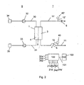
- Fig. 2 shows a hemodialysis device with an extra-corporeal blood circuit comprising a first system 40 and a second identical system 40' as depicted in Fig. 1 .
- blood of a patient (not shown) is circulated in an extra-corporeal blood circuit 7 from an arterial blood line 11 to a hemodialyser 1.
- the hemodialyser 1 is separated by a semipermeable membrane 2 that is usually embodied by a bundle of hollow fibres in a first compartment 3 (blood compartment), that is part of the extra-corporeal blood circuit 7, and a second compartment 4 (dialysate compartment), that is part of a dialysate circuit 8.
- Substances to be removed by the blood treatment pass the membrane 2 from the blood compartment 3 to the dialysate compartment 4 and are removed by the dialysate that circulates though the dialysate compartment 4. At the same time excess fluid in the blood can be removed from the blood by applying an appropriate pressure gradient across the membrane 2.
- a diffusion gradient can be used to transfer substances present in the fresh dialysate like electrolytes into or remove them from the blood to achieve a certain concentration level of these substances in the blood.
- the blood is circulated by a blood pump 5 that may be a conventional roller pump.
- the blood enters the blood compartment 3 of the dialyser 1 via the arterial blood line 11 and leaves it via the venous blood line 11' by which the blood is re-infused into the patient (not shown).
- a venous clamp 6 is mounted on the venous blood line 11'. The venous clamp 6 can be closed whenever the re-infusion of the blood should be interrupted because of safety reasons. An example for such a safety reason is the detection of a certain amount of air in the venous blood 11' by an air sensor (not shown).
- the second compartment 4 of the hemodialyser 1 is connected with a dialysate inlet line 30 by which dialysate fluid is guided from a dialysate preparation unit 34 to the second compartment 4. It is also connected with a dialysate outlet line 31 by which the dialysate is guided from the second compartment 4 to a drain 35.
- the dialysate is circulated by pumping and balancing means 32 and 33 by which the fluid rates in the dialysate inlet and outlet lines 30 and 31 and thus also the ultrafiltration rate by which fluid is extracted from the blood can be accurately controlled.
- Embodiments for such pumping and balancing means 32 and 33 are well known in the art.
- the same applies for the dialysate preparation unit 34 An example embodiment for the pumping and balancing means 32 and 33 and the dialysate preparation unit 34 is described in US 4,267,040 .
- the hemodialysis device is controlled and monitored by a control unit 100.
- the control unit 100 is connected with the various sensors and actuators of the device by signal connections. This may be wire or wireless connections.
- signal connections This may be wire or wireless connections.
- Fig. 2 these connections are depicted schematically by using the same reference numbers for the connections and the connected sensors/actuators wherein the suffix 'a' is added for the connections. For clarity only those ends of the connections are shown in Fig. 2 that terminate at the control unit 100.
- the control unit 100 is further connected with an input and output unit 102 by a data link 101.
- the input and output unit 102 may comprise a touchscreen 103 that can be used to display selected information that is provided by the control unit 100. At the same time a user may enter further data and/or instructions into the control unit 100 by using the touchscreen 103.
- the hemodialysis device as shown in Fig. 2 also comprises a system 40 according to the invention as shown in detail in Fig. 1 .
- a pressure transducer line 12 branches off that leads to an arterial pressure transducer.
- the system 40 is only depicted symbolically. The same applies for an identical system 40' that comprises a pressure transducer line 12' branching off the venous blood line 11' and leading to a venous pressure transducer.
- the wire connections 21a and 24a as shown in Fig. 1 are connected with the control unit 100 as shown in Fig. 2 . This applies to the connections 21 a' and 24a' of the second system 40' also. Using these connections the control unit 100 receives signals from the sensor 24 of the system 40 and the corresponding sensor 24' of the system 40'. The sensors emit a first signal to the control unit 100 if no blood is detected by the sensor, and a second signal if blood is detected.
- This terminology is not limited to a system and device where the sensor processes the measurement signal itself and as a result transmits only two kinds of signals in the sense of 'yes' or 'no'.
- the sensor may transmit signals that are partly pre-processed by the sensor electronic circuits, or not pre-processed at all.
- the first signal only has to be distinct from the second signal.
- the first signal may hence comprise a first range of signal values and the second signal a second range of signal values, both ranges being separated by a threshold value.
- the signals are not pre-processed and the sensor produces pairs or multiples of signals as in the case of an optical sensor that probes the transparency at two wavelengths, such a pair or multiple of signals will be directly processed by the control unit 100.
- the transmission of such pair or multiple signals to enable the derivation of a final result is considered to be encompassed by the wording that the sensor emits first and second signals dependent on the presence of the liquid in the pressure transducer section 12B.
- the control unit 100 will send a corresponding signal to the input and output unit 102 so that an alarm signal will be displayed on the touchscreen 103 to make a user aware of a pressure transducer protector filter integrity problem in either of the pressure transducer lines.
- the user will be notified in which of the two pressure transducer lines the alarm condition was detected.
- Other alarm signals like audible alarms and/or transmitting alarm signal to remote locations by a communication network may also be initiated by the control unit 100.
- the control unit 100 may advice the venous clamp 6 to close the venous blood line 11' and the other pumps to stop or to switch into a special pause mode if required.
- the corresponding blood line set comprises only the disposable blood set part 10 of the systems 40 and 40', respectively.
- the hemodialysis device itself without the blood lines, only requires to contain the components of the re-usable device 20 of the systems 40 and 40' as outlined above in the context with the description of Fig. 1 .
- the housing 23 is preferably the housing of the hemodialysis device.
- the housing connector 14B is mounted by which a user can connect the disposable connector 14A of the blood line set.
- the other components of the re-usable device 20 are preferably contained inside the housing 23 or at least as shown in Fig. 1 .
- the user only has to access these components in case of a faulty part as in the case when blood has been sensed by the sensor 24. It may then be necessary to replace the housing section 12F of the pressure transducer line 12 and the second pressure transducer protector filter 22.
- the housing 23 of the hemodialysis device may then be opened as for technical maintenance or some other suitable way to allow access to the components.
- control unit 100 may check the integrity of the system at any time before, during or after a blood treatment.
- a check of the integrity by probing the presence of the priming fluid can avoid any otherwise necessary trouble shooting during the blood treatment in case the checks are only taking place during the blood treatment.
- Regular checks should be performed to ensure that the sensor is correctly working wherein conventional fail safe techniques may be applied. Should a problem be detected just after a blood treatment this is also helpful as an early exchange of the necessary parts is enabled.
- the system and the device according to the invention provide an easy and efficient way to avoid blood contamination problems and the non-detection of faulty pressure transducer protector filters particularly in blood treatment devices where the pressure in blood lines has to be routinely monitored at one or more locations.
- a higher hygienic standard can thus be achieved.
- the device according to the invention may be integrated in a blood treatment device during the manufacturing process. As the number of additional components is low it is also easily possible to use the device according to the invention in older blood treatment devices by installing appropriate retrofit kits. Such kits only require a software update for the control unit of the blood treatment device and the additional sensor for detecting the presence of the liquid in the pressure transducer section of the pressure transducer line.
- the invention may be used for any line carrying blood or any components of blood to be processed by a blood treatment device. It is not limited to the processing of whole blood.
Description
- The invention relates to the area of pressure monitoring devices for blood lines, eg. see
EP 1547630 . - In an extra-corporeal blood treatment blood is extracted from a patient, circulated in an extra-corporeal blood circuit that comprises a blood treatment unit, and infused back to the patient. Examples for such blood treatments are procedures to be used in case of kidney failure like hemodialysis, hemofiltration or hemodiafiltration. For other organ failures or diseases examples for blood treatments comprise blood oxygenation, blood component separation by centrifuge or filter techniques, or the removal of blood components by adsorption.
- During the blood treatment blood is continuously or quasi-continuously circulated in the blood lines of the extra-corporeal blood circuit. In order to monitor the conditions in the extra-corporeal blood circuit the pressure in the arterial blood line leading from the patient to the blood treatment unit and in the venous blood line leading from the blood treatment unit to the patient are continuously measured. In contemporary devices this is accomplished by pressure transducer lines branching off the arterial and the venous lines, respectively, and leading to pressure transducers that are part of the blood treatment device.
- To avoid any contamination of the pressure transducers and thus the blood treatment device a first pressure transducer protector filter is used that is dividing the pressure transducer line into a blood line section between the blood line and the filter and a pressure transducer section between the filter and the pressure transducer. Such a contamination is not desirable in view of a possible cross-contamination of the blood of a patient that is treated later with the same device. In addition, the spilled blood may damage the pressure sensor itself and the corresponding electronic circuits.
- The pressure transducer protector filter is permeable by a gas like air but not by a liquid like blood. For this purpose preferably hydrophobic filter materials are used. Furthermore, the membrane element in the filter has pores small enough to block the transfer of matter like bacteria and germs that may compromise the sterile hygienic conditions in either side of the filter whenever air passes the filter.
- The pressure transducer section is usually separable by connector means comprising a connector and a mating connector. It is thus possible to exchange and dispose the blood lines of the extra-corporeal circuit and the part of the pressure transducer line comprising the blood line section, the first pressure transducer protector filter and the pressure transducer section extending from the filter to the connector means after a blood treatment. These parts may be manufactured as a single piece blood line set. The remaining part of the pressure transducer line and the pressure transducer itself are part of the blood treatment device and are re-used for the next patient. As the first pressure transducer protector filter protects these parts from any blood contact there is no need to exchange them after proper use.
- At the start of a treatment a new blood line set is mounted on the blood treatment device and the pressure transducer lines of the blood line set are connected with the help of the connector means to the blood treatment device. When the extra-corporeal blood circuit is primed with a priming solution before a patient is connected, a certain amount of air is trapped in the pressure transducer lines. The air nevertheless transmits the pressure from the corresponding blood line to the pressure transducer. When the pressure rises the air volume will be compressed, but the geometry of the lines is designed so that under normal conditions the blood level will not reach the first pressure transducer protector filter as otherwise the danger arises that the filter is blocked by the blood and that the pressure can no longer be properly transmitted though the filter.
- As long as the integrity of the first filter is not damaged the blood cannot enter the pressure transducer section of the pressure transducer line and any contamination is avoided. As all parts of the blood line set that get into contact with the blood are replaced with new and sterile ones before the next patient is treated, cross-contamination cannot occur. The situation is however different should the first pressure transducer protector filter have a rupture. In this case blood can leak through the ruptured filter into the pressure transducer section. Contemporary hemodialysis devices therefore have a second pressure transducer protector filter in the pressure transducer section. The second filter is arranged inside the housing of the hemodialysis device and divides the pressure transducer section in a first part between the two filters and a second part between the second filter and the pressure transducer. This second filter is not part of the disposable blood line set and serves for redundancy purposes only. Should a blood leak occur in the first pressure transducer protector filter, the second pressure transducer protector filter still avoids any contamination and/or damage of the parts behind the second filter, in particular of the pressure transducer.
- This prior art arrangement has the disadvantage that a rupture of the first filter is not necessarily noticed by the user of the blood treatment device. Any blood that passed the first filter may have contaminated any part of the first part of the pressure transducer section. In addition the membrane element of the second pressure transducer protector filter may have been at least partially blocked by the leaked blood. Though the pressure transducer is still protected by the second filter, this filter may no longer properly transmit the air pressure. Last not least, if not noticed by a user, the blood remaining in the first part of the pressure transducer section is not removed by exchanging the disposable blood line set, thus giving rise to a possible hygienic problem.
- It is therefore an object of the present invention to provide a system by which an unnoticed failure of the first pressure transducer protector filter in a pressure transducer line is avoided. This problem is solved by a system according to
claim 1. Preferred embodiments are the subject of the dependent claims. - The invention provides a system for monitoring the pressure in a blood line, the system comprising a blood line, a pressure transducer line branching off the blood line and leading to a pressure transducer for measuring the pressure in the pressure transducer line, a first pressure transducer protector filter in the pressure transducer line dividing the pressure transducer line into a blood line section between the blood line and the filter and a pressure transducer section between the filter and the pressure transducer, the first pressure transducer protector filter being permeable by a gas but not by a liquid, wherein the system further comprises a sensor for detecting the presence of a liquid in the pressure transducer section of the pressure transducer line.
- Should the first pressure transducer protector filter have a rupture, leaking liquid will enter the pressure transducer section where the leaking liquid will be detected by the sensor that is arranged in this region of the pressure transducer line. In a preferred embodiment of the invention the leaking liquid to be detected is blood or saline. Saline may be used as priming fluid for the blood line and as a kind of buffer between the blood in the blood line and the trapped air in the pressure transducer line to avoid any direct blood-air contact. In this case saline will primarily leak through the ruptured filter instead of blood. Any other liquid serving the same purpose may also be used. The sensor has then to be selected dependent on what leaking liquid should be detected by the sensor.
- In a specific embodiment of the invention the sensor is an optical sensor probing optical properties in the pressure transducer section, preferably the transparency of the pressure transducer section selectively at two light wavelengths.
- In another embodiment of the invention the sensor is an electrical sensor probing electrical properties in the pressure transducer section, in particular at least one of conductivity, capacity or inductance.
- In a still further embodiment of the invention the sensor is an ultrasonic sensor comprising an ultrasonic transmitter and an ultrasonic transducer. With the aid of the ultrasonic sensor the transit times of ultrasonic signals through the pressure transducer section may be exploited to detect the presence of any liquid in this line.
- In another embodiment of the invention the sensor is a first sensor for detecting a first liquid wherein the system further comprises a second sensor for detecting the presence of a second liquid in the pressure transducer section of the pressure transducer line. The first sensor may be used to detect a first leaking liquid like blood, the second sensor to detect a second leaking fluid like priming fluid, depending on the sensitivities of the sensors relative to the liquids to be detected. As an example an optical sensor may be utilised for detecting the first fluid like blood, an ultrasonic sensor for detecting the second fluid like priming fluid. Two optical sensors using different optical wavelengths are a further example.
- Depending on the coupling of the sensor or the sensors to the pressure transducer section either conventional tubing systems or particularly shaped probe chambers like cuvettes may be used.
- In a still further embodiment of the invention the system further comprises a second pressure transducer filter dividing the pressure transducer section into a first part between the filters and a second part between the second filter and the pressure transducer, wherein the second pressure transducer protector filter is also permeable by the gas but not by the liquid, and wherein the sensor detects the presence of the liquid in the first part of the pressure transducer section.
- The pressure transducer and the second pressure transducer protector filter may be fastened to a housing. The first part of the pressure transducer section may be separable by connector means comprising a connector and a mating connector, dividing the pressure transducer section into a housing section leading to the second pressure transducer protector filter and into a disposable section leading to the first pressure transducer protector filter, wherein the sensor detects the presence of the liquid in the housing section of the first part of the pressure transducer section.
- It is also an object of the invention to provide a device to be used in a system as described above by which an unnoticed failure of the first pressure transducer protector filter in the pressure transducer line is avoided and wherein the device itself can easily be re-used. This problem is solved by a device according to claim 15. Preferred embodiments are the subject of the dependent claims.
- The device according to the invention comprises the housing part of the embodiment of the system according to the invention where the system consists of a disposable and a housing part. The housing part comprises the mating connector, the second pressure transducer protector filter, the sensor for detecting the presence of the liquid in the pressure transducer section, the housing section of the first part of the pressure transducer section between the mating connector and the second pressure transducer protector filter, the second part of the pressure transducer section and the pressure transducer. By joining the connector of the corresponding disposable part of the system according to the invention with the mating connector of such a device it is possible to detect any liquid leaking through a rupture in the first pressure transducer protector filter. In addition, the device can easily be re-used by disconnecting the disposable part with the help of the connector means from the device. The disposable part can safely be discarded after use and be replaced by a new disposable part, e.g. blood line set, before the next treatment.
- In a particular advantageous embodiment of the invention the device is a blood treatment device with a control unit for controlling and monitoring a blood treatment of blood that is circulated in an extra-corporeal blood circuit. In this case the extra-corporeal blood circuit further comprises one or more blood lines having pressure transducer lines branching off the blood lines by which the pressure in the blood lines is determined by the control unit of the blood treatment device with the aid of the pressure transducers. For the treatment itself the extra-corporeal blood is circulated through a blood treatment unit. Examples of such devices are hemodialysis, hemofiltration or hemodiafiltration devices where the blood treatment unit is a hemodialyser and/or hemofilter.
- In a further embodiment of the invention the sensor for detecting the presence of a liquid is connected with the control unit of the blood treatment device wherein the sensor emits a first signal to the control unit if no fluid is detected and a second signal to the control unit if the fluid is detected. The control unit may emit an alarm signal in case the second signal is received from the sensor.
- The advantages of the concept of the invention will become more apparent from an embodiment of the invention that is described as an example with the aid of the figures. The figures show schematically in
- Fig. 1
- an embodiment of a system according to the invention consisting of a re-usable device according to the invention and a disposable part, and
- Fig. 2
- a hemodialysis device with an extra-corporeal blood circuit comprising two systems as depicted in
Fig. 1 . - In
Fig. 1 an example embodiment of asystem 40 according to the invention is shown. It consists of adisposable part 10 being part of a disposable blood line set that can be exchanged after each use, and are-usable device 20 whose parts are not exchanged after each use. Thedisposable part 10 comprises ablood line 11 from which theblood line section 12A of apressure transducer line 12 branches off. The lines may be designed as a conventional tubing set. As an alternative the lines may also be made as any kind of fluid guiding channels, in particular as a part of a cartridge having rigid and/or flexible components. The pressure transducer line may branch off a blood tube directly or be accomplished as a part of a component like an air trap that is passed by the blood. In fact it is only necessary that thepressure transducer line 12 is in fluid contact with theblood line 10 so that the pressure can be transmitted though thepressure transducer line 12. - The
pressure transducer line 12 is divided by a first pressuretransducer protector filter 13 into ablood line section 12A between theblood line 11 and thefirst filter 13 and apressure transducer section 12B between thefirst filter 13 and apressure transducer 21. With the aid of thepressure transducer 21 the pressure in thepressure transducer line 12 and thus theblood line 11 is measured. As an example the transducer may contain a piezoelectric element that converts the force and thus the pressure applied to it into an electrical signal as is well known in the art. - The
pressure transducer section 12B is further divided by a second pressuretransducer protector filter 22 into afirst part 12C between the two filters and asecond part 12D between thesecond filter 22 and thepressure transducer 21 as shown inFig. 1 . Thefirst part 12C is divided by connector means 14 into adisposable section 12E and ahousing section 12F. The connector means 14 comprises adisposable connector 14A mating with ahousing connector 14B. Such connectors may be standard Luer lock connectors. The first and second pressure transducer protector filters 13 and 22 comprise hydrophobicfilter membrane elements - The
disposable section 12E extends from the first pressuretransducer protector filter 13 to thedisposable connector 14A. Thehousing section 12F extends from thehousing connector 14B to the second pressuretransducer protector filter 22. Such an arrangement allows an easy exchange of thedisposable part 10 in this embodiment of the system according to the invention by disconnecting thedisposable connector 14A from thehousing connector 14B and replacing a useddisposable part 10 by a new and sterile one. - The
re-usable device 20 of thesystem 40 comprises a housing 23 to which thehousing section 12F, thesecond part 12D of thepressure transducer section 12B, the second pressuretransducer protector filter 22 and thepressure transducer 21 withwire connections 21a are fastened. For this purpose it is not necessary to fix all such components individually to the housing 23 as long as the ensemble is sufficiently secured to it. - In the
pressure transducer section 12B asensor 24 withwire connections 24a is positioned. This sensor is an optical sensor element measuring the transparency of thepressure transducer section 12B at two suitable optical wavelengths or at least two distinct light colours. The first wavelength is chosen as a reference, the second as a wavelength being specific for the presence of the liquid to be detected, i.e. blood. Such two-colour sensors are already used for sensing the presence of blood in other parts of a blood treatment device and are known to the person skilled in the art. As a common example such a sensor may use a red and a green LED as colour selective light sources. The lights sources are preferably powered at a selected frequency so that their signal components in the detector signals can easily be filtered from any disturbing scattered light signals by conventional techniques. As light detectors any light sensitive devices like photo diodes or transistors may be employed. - Alternative sensor embodiments may probe other properties, in particular electrical properties, of the
pressure transducer section 12B in order to detect the presence of the liquid. Electrodes may be attached from the exterior to thepressure transducer section 12B and an alternating current source be applied to the electrodes to probe the conductivity or capacity of the arrangement. Depending on the liquid to be detected measurements utilising inductance may also be possible. - In case no blood is detected by the
sensor 24 the sensor emits a first signal via thewire connections 24a to a control unit not shown inFig. 1 . Should blood enter thepressure transducer section 12B in case of a leak in the first pressuretransducer protector filter 13, the optical properties of thepressure transducer section 12B will specifically change and thesensor 24 will emit a second signal to the control unit that is different to the first signal. Thesensor 24 thus enables thesystem 40 to notify any user of the failure of the first pressuretransducer protector filter 13. - In the embodiment as shown in
Fig. 1 thesensor 24 is positioned between the housing 23 and the second pressuretransducer protector filter 22, i.e. not on the side that is directly accessible by a user that usually has direct access to the connector means 14 to replace thedisposable part 10. InFig. 1 an alternative arrangement is also shown where thesensor 24" is positioned between the housing 23 and thehousing connector 14B. Depending on theindividual device 20 one of the two alternatives may be preferable. -
Fig. 2 shows a hemodialysis device with an extra-corporeal blood circuit comprising afirst system 40 and a second identical system 40' as depicted inFig. 1 . In hemodialysis blood of a patient (not shown) is circulated in anextra-corporeal blood circuit 7 from anarterial blood line 11 to ahemodialyser 1. Thehemodialyser 1 is separated by asemipermeable membrane 2 that is usually embodied by a bundle of hollow fibres in a first compartment 3 (blood compartment), that is part of theextra-corporeal blood circuit 7, and a second compartment 4 (dialysate compartment), that is part of adialysate circuit 8. Substances to be removed by the blood treatment pass themembrane 2 from theblood compartment 3 to thedialysate compartment 4 and are removed by the dialysate that circulates though thedialysate compartment 4. At the same time excess fluid in the blood can be removed from the blood by applying an appropriate pressure gradient across themembrane 2. A diffusion gradient can be used to transfer substances present in the fresh dialysate like electrolytes into or remove them from the blood to achieve a certain concentration level of these substances in the blood. - The blood is circulated by a
blood pump 5 that may be a conventional roller pump. The blood enters theblood compartment 3 of thedialyser 1 via thearterial blood line 11 and leaves it via the venous blood line 11' by which the blood is re-infused into the patient (not shown). Avenous clamp 6 is mounted on the venous blood line 11'. Thevenous clamp 6 can be closed whenever the re-infusion of the blood should be interrupted because of safety reasons. An example for such a safety reason is the detection of a certain amount of air in the venous blood 11' by an air sensor (not shown). - The
second compartment 4 of thehemodialyser 1 is connected with adialysate inlet line 30 by which dialysate fluid is guided from adialysate preparation unit 34 to thesecond compartment 4. It is also connected with adialysate outlet line 31 by which the dialysate is guided from thesecond compartment 4 to adrain 35. The dialysate is circulated by pumping and balancing means 32 and 33 by which the fluid rates in the dialysate inlet andoutlet lines dialysate preparation unit 34. An example embodiment for the pumping and balancing means 32 and 33 and thedialysate preparation unit 34 is described inUS 4,267,040 . - Conventional hemodialysis devices contain many further components as is also well known in the art. For the purpose of simplicity the description of
Fig. 2 is limited to those components that appear to be sufficient for the understanding of the concept of the present invention. - The hemodialysis device is controlled and monitored by a
control unit 100. For this reason thecontrol unit 100 is connected with the various sensors and actuators of the device by signal connections. This may be wire or wireless connections. InFig. 2 these connections are depicted schematically by using the same reference numbers for the connections and the connected sensors/actuators wherein the suffix 'a' is added for the connections. For clarity only those ends of the connections are shown inFig. 2 that terminate at thecontrol unit 100. - The
control unit 100 is further connected with an input andoutput unit 102 by adata link 101. The input andoutput unit 102 may comprise atouchscreen 103 that can be used to display selected information that is provided by thecontrol unit 100. At the same time a user may enter further data and/or instructions into thecontrol unit 100 by using thetouchscreen 103. - The hemodialysis device as shown in
Fig. 2 also comprises asystem 40 according to the invention as shown in detail inFig. 1 . From thearterial blood line 11 of the extra-corporeal blood circuit 7 apressure transducer line 12 branches off that leads to an arterial pressure transducer. InFig. 2 thesystem 40 is only depicted symbolically. The same applies for an identical system 40' that comprises a pressure transducer line 12' branching off the venous blood line 11' and leading to a venous pressure transducer. - The
wire connections Fig. 1 are connected with thecontrol unit 100 as shown inFig. 2 . This applies to theconnections 21 a' and 24a' of the second system 40' also. Using these connections thecontrol unit 100 receives signals from thesensor 24 of thesystem 40 and the corresponding sensor 24' of the system 40'. The sensors emit a first signal to thecontrol unit 100 if no blood is detected by the sensor, and a second signal if blood is detected. This terminology is not limited to a system and device where the sensor processes the measurement signal itself and as a result transmits only two kinds of signals in the sense of 'yes' or 'no'. The sensor may transmit signals that are partly pre-processed by the sensor electronic circuits, or not pre-processed at all. The first signal only has to be distinct from the second signal. The first signal may hence comprise a first range of signal values and the second signal a second range of signal values, both ranges being separated by a threshold value. In case the signals are not pre-processed and the sensor produces pairs or multiples of signals as in the case of an optical sensor that probes the transparency at two wavelengths, such a pair or multiple of signals will be directly processed by thecontrol unit 100. Though the final transparency result is then calculated by the control unit, the transmission of such pair or multiple signals to enable the derivation of a final result is considered to be encompassed by the wording that the sensor emits first and second signals dependent on the presence of the liquid in thepressure transducer section 12B. - In case at least one of the
sensors 24 or 24' emits the second signal to thecontrol unit 100 this unit will sent a corresponding signal to the input andoutput unit 102 so that an alarm signal will be displayed on thetouchscreen 103 to make a user aware of a pressure transducer protector filter integrity problem in either of the pressure transducer lines. Preferably the user will be notified in which of the two pressure transducer lines the alarm condition was detected. Other alarm signals like audible alarms and/or transmitting alarm signal to remote locations by a communication network may also be initiated by thecontrol unit 100. As an optional further feedback thecontrol unit 100 may advice thevenous clamp 6 to close the venous blood line 11' and the other pumps to stop or to switch into a special pause mode if required. - As the blood lines of the
extra-corporeal blood circuit 7 are usually disposed after a blood treatment the corresponding blood line set comprises only the disposable blood setpart 10 of thesystems 40 and 40', respectively. The hemodialysis device itself, without the blood lines, only requires to contain the components of there-usable device 20 of thesystems 40 and 40' as outlined above in the context with the description ofFig. 1 . In this case the housing 23 is preferably the housing of the hemodialysis device. On the outside of the housing thehousing connector 14B is mounted by which a user can connect thedisposable connector 14A of the blood line set. The other components of there-usable device 20 are preferably contained inside the housing 23 or at least as shown inFig. 1 . The user only has to access these components in case of a faulty part as in the case when blood has been sensed by thesensor 24. It may then be necessary to replace thehousing section 12F of thepressure transducer line 12 and the second pressuretransducer protector filter 22. The housing 23 of the hemodialysis device may then be opened as for technical maintenance or some other suitable way to allow access to the components. - With the aid of the
sensor 24 thecontrol unit 100 may check the integrity of the system at any time before, during or after a blood treatment. In particular during the priming process a check of the integrity by probing the presence of the priming fluid can avoid any otherwise necessary trouble shooting during the blood treatment in case the checks are only taking place during the blood treatment. Regular checks should be performed to ensure that the sensor is correctly working wherein conventional fail safe techniques may be applied. Should a problem be detected just after a blood treatment this is also helpful as an early exchange of the necessary parts is enabled. - The system and the device according to the invention provide an easy and efficient way to avoid blood contamination problems and the non-detection of faulty pressure transducer protector filters particularly in blood treatment devices where the pressure in blood lines has to be routinely monitored at one or more locations. A higher hygienic standard can thus be achieved. The device according to the invention may be integrated in a blood treatment device during the manufacturing process. As the number of additional components is low it is also easily possible to use the device according to the invention in older blood treatment devices by installing appropriate retrofit kits. Such kits only require a software update for the control unit of the blood treatment device and the additional sensor for detecting the presence of the liquid in the pressure transducer section of the pressure transducer line.
- The invention may be used for any line carrying blood or any components of blood to be processed by a blood treatment device. It is not limited to the processing of whole blood.
Claims (14)
- System (40; 40') for monitoring the pressure in a blood line (11; 11') comprising
a blood line (11; 11'),
a pressure transducer line (12; 12') branching off the blood line (11; 11'),
a pressure transducer (21), the pressure transducer line (12; 12') leading to the pressure transducer (21) for measuring the pressure in the pressure transducer line (12, 12'),
a first pressure transducer protector filter (13) in the pressure transducer line (12; 12') dividing the pressure transducer line into a blood line section (12A) between the blood line (11; 11') and the first filter (13) and a pressure transducer section (12B) between the first filter (13) and the pressure transducer (21), the first pressure transducer protector filter (13) being permeable by a gas, in particular air, but not by a liquid
wherein the system further comprises a sensor (24; 24") for detecting the presence of the liquid in the pressure transducer section (12B) of the pressure transducer line (12; 12'),
wherein the sensor is one of
an optical sensor probing optical properties in the pressure transducer section (12B), the sensor measuring the transparency of the pressure transducer section (12B) selectively at two light wavelengths or at least selectively for two light colours,
an electrical sensor probing electrical properties, in particular the conductivity, capacity or inductance, in the pressure transducer section (12B) and
an ultrasonic sensor comprising an ultrasonic transmitter and an ultrasonic transducer. - System according to claim 1 characterised in that the liquid is blood or saline.
- System according to any of the preceding claims characterised in that the sensor (24; 24") is a first sensor for detecting a first liquid wherein the system further comprises a second sensor for detecting the presence of a second liquid in the pressure transducer section (12B) of the pressure transducer line (12; 12').
- System according to any of the preceding claims characterised in that the system (40) further comprises a second pressure transducer protector filter (22) dividing the pressure transducer section (12B) in a first part (12C) between the two filters (13, 22) and a second part (12D) between the second filter (22) and the pressure transducer (21), wherein the second pressure transducer protector filter (22) is also permeable by the gas but not by the liquid, and wherein the sensor (24; 24") detects the presence of the liquid in the first part (12C) of the pressure transducer section (12B).
- System according to claim 4 characterised in that the first part (12C) can be separated and joined by connector means (14) comprising a connector (14A) and a mating connector (14B).
- System according to claim 5 characterised in that the system (40) is divided by the connector means (14) into a disposable part (10) and a housing part (20), the disposable part comprising the blood line (11), the blood line section (12A)" the first pressure transducer protector filter (13), the connector (14A) and a disposable section (12E) of the first part (12C) of the pressure transducer section (12B) between the first pressure transducer protector filter (13) and the connector (14A), and the housing part comprising the mating connector (14B), the second pressure transducer protector filter (22), the sensor (24; 24"), a housing section (12F) of the first part (12C) of the pressure transducer section (12B) between the mating connector (14B) and the second pressure transducer protector filter (22), the second part (12D) of the pressure transducer section (12B) and the pressure transducer (21).
- System according to claim 6 characterised that the housing part (20) further comprises a housing (23) to which the other components of the housing part are fastened.
- System according to claim 7 characterised in that the sensor (24) is positioned between the housing (23) and the second pressure transducer protector filter (22).
- System according to claim 8 characterised in that the sensor (24") is positioned between the housing (23) and the housing connector (14B).
- Device to be used in a system according to any of the claims 6 to 9 characterised in that it comprises the housing part (20) of the system (40), comprising the mating connector (14B), the second pressure transducer protector filter (22), the sensor (24; 24"), the housing section (12F) of the first part (12C) of the pressure transducer section (12B) between the mating connector (14B) and the second pressure transducer protector filter (22), the second part (12D) of the pressure transducer section (12B) and the pressure transducer (21).
- Device according to claim 10 characterised in that the device is a blood treatment device, the device further comprising a control unit (100) for controlling and monitoring a blood treatment of blood circulating in an extra-corporeal blood circuit (7) wherein the blood line (11; 11') is a part of the extra-corporeal blood circuit (7).
- Device according to claim 11 characterised in that the device is a hemodialysis, hemofiltration of hemodiafiltration device.
- Device according to claims 11 or 12 characterised in that the sensor (24; 24") is connected with the control unit (100) and that the sensor (24; 24") emits a first signal to the control unit (100) if no fluid is detected and a second signal to the control unit (100) if the fluid is detected.
- Device according to claim 13 characterised in that the control unit (100) is emitting an alarm signal in case it receives the second signal.
Priority Applications (6)
| Application Number | Priority Date | Filing Date | Title |
|---|---|---|---|
| ES05011997T ES2398526T3 (en) | 2005-06-03 | 2005-06-03 | System for monitoring the pressure in a bloodstream and device for use with such a system |
| EP05011997A EP1728526B1 (en) | 2005-06-03 | 2005-06-03 | System for monitoring the pressure in a blood line and a device to be used with such a system |
| PL05011997T PL1728526T3 (en) | 2005-06-03 | 2005-06-03 | System for monitoring the pressure in a blood line and a device to be used with such a system |
| JP2006154860A JP4959229B2 (en) | 2005-06-03 | 2006-06-02 | System for monitoring pressure in blood line and device used therefor |
| CN2006100887186A CN1872358B (en) | 2005-06-03 | 2006-06-02 | System for monitoring the pressure in a blood line and a device to be used with such a system |
| US11/446,499 US8241237B2 (en) | 2005-06-03 | 2006-06-05 | System for monitoring the pressure in a blood line and a device to be used in such a system |
Applications Claiming Priority (1)
| Application Number | Priority Date | Filing Date | Title |
|---|---|---|---|
| EP05011997A EP1728526B1 (en) | 2005-06-03 | 2005-06-03 | System for monitoring the pressure in a blood line and a device to be used with such a system |
Publications (2)
| Publication Number | Publication Date |
|---|---|
| EP1728526A1 EP1728526A1 (en) | 2006-12-06 |
| EP1728526B1 true EP1728526B1 (en) | 2012-12-26 |
Family
ID=35517365
Family Applications (1)
| Application Number | Title | Priority Date | Filing Date |
|---|---|---|---|
| EP05011997A Not-in-force EP1728526B1 (en) | 2005-06-03 | 2005-06-03 | System for monitoring the pressure in a blood line and a device to be used with such a system |
Country Status (6)
| Country | Link |
|---|---|
| US (1) | US8241237B2 (en) |
| EP (1) | EP1728526B1 (en) |
| JP (1) | JP4959229B2 (en) |
| CN (1) | CN1872358B (en) |
| ES (1) | ES2398526T3 (en) |
| PL (1) | PL1728526T3 (en) |
Cited By (6)
| Publication number | Priority date | Publication date | Assignee | Title |
|---|---|---|---|---|
| US8500994B2 (en) | 2010-01-07 | 2013-08-06 | Fresenius Medical Care Holdings, Inc. | Dialysis systems and methods |
| US8506684B2 (en) | 2010-12-15 | 2013-08-13 | Fresenius Medical Care Holdings, Inc. | Gas release devices for extracorporeal fluid circuits and related methods |
| US8663463B2 (en) | 2009-02-18 | 2014-03-04 | Fresenius Medical Care Holdings, Inc. | Extracorporeal fluid circuit and related components |
| US8974405B2 (en) | 2005-10-21 | 2015-03-10 | Fresenius Medical Care Holdings, Inc. | Extracorporeal fluid circuit |
| US9220832B2 (en) | 2010-01-07 | 2015-12-29 | Fresenius Medical Care Holdings, Inc. | Dialysis systems and methods |
| US9375526B2 (en) | 2013-06-25 | 2016-06-28 | Fresenius Medical Care Holdings, Inc. | Vial spiking assemblies and related methods |
Families Citing this family (22)
| Publication number | Priority date | Publication date | Assignee | Title |
|---|---|---|---|---|
| CN101868262B (en) | 2007-09-19 | 2013-11-06 | 弗雷塞尼斯医疗保健控股公司 | Safety vent structure for extracorporeal circuit |
| EP3150238B1 (en) | 2007-09-19 | 2018-03-14 | Fresenius Medical Care Holdings, Inc. | Dialysis systems and related components |
| EP2229966A1 (en) | 2009-03-18 | 2010-09-22 | Fresenius Medical Care Deutschland GmbH | Safety insert for extra-corporeal circuits |
| EP2253343A1 (en) * | 2009-05-19 | 2010-11-24 | Fresenius Medical Care Deutschland GmbH | Safety insert for extra-corporeal circuits |
| ES2613944T3 (en) | 2009-12-17 | 2017-05-29 | Gambro Lundia Ab | Apparatus for the treatment of extracorporeal blood and method of operation |
| US9375524B2 (en) | 2011-06-03 | 2016-06-28 | Fresenius Medical Care Holdings, Inc. | Method and arrangement for venting gases from a container having a powdered concentrate for use in hemodialysis |
| CN102698328B (en) * | 2012-06-08 | 2014-12-03 | 李广成 | Double-container balanced lavaging device for hematoma remover |
| CN102698329B (en) * | 2012-06-08 | 2015-01-21 | 李广成 | Balance lavage device for hematoma remover |
| EP2737918B1 (en) | 2012-11-29 | 2016-06-01 | Gambro Lundia AB | Hemodialysis on-line port leak detection |
| US9808567B2 (en) | 2012-12-14 | 2017-11-07 | Gambro Lundia Ab | Diaphragm repositioning for pressure pod using position sensing |
| CN103110411A (en) * | 2013-01-21 | 2013-05-22 | 北京大德海纳医疗科技有限公司 | Arteriovenous pressure monitoring device under condition of rocking vibration wild battlefield |
| DE102013006562A1 (en) * | 2013-04-16 | 2014-10-16 | Fresenius Medical Care Deutschland Gmbh | Method for determining the pressure in an extracorporeal circuit |
| DE102013106582A1 (en) * | 2013-06-24 | 2014-12-24 | Ulrich Gmbh & Co. Kg | Pressure measuring cell for use in an infusion or injection system |
| US10220132B2 (en) | 2014-12-19 | 2019-03-05 | Fenwal, Inc. | Biological fluid flow control apparatus and method |
| US9974942B2 (en) | 2015-06-19 | 2018-05-22 | Fresenius Medical Care Holdings, Inc. | Non-vented vial drug delivery |
| US9945838B2 (en) | 2015-12-17 | 2018-04-17 | Fresenius Medical Care Holdings, Inc. | Extracorporeal circuit blood chamber having an integrated deaeration device |
| DE102015016842A1 (en) | 2015-12-23 | 2017-06-29 | Fresenius Medical Care Deutschland Gmbh | Method and device for checking a dialyzer for the presence of a leak |
| CN106289630B (en) * | 2016-09-30 | 2019-07-19 | 四川南格尔生物科技有限公司 | A kind of loine pressure acquisition device and acquisition method |
| JP6483874B1 (en) * | 2018-01-18 | 2019-03-13 | 日機装株式会社 | Pressure detector adjustment device |
| JP6637108B2 (en) * | 2018-05-16 | 2020-01-29 | 日機装株式会社 | Pressure detector |
| CN110339414B (en) * | 2019-06-27 | 2022-02-11 | 健帆生物科技集团股份有限公司 | Pressure detection device for blood purification system and medical equipment |
| USD979050S1 (en) | 2019-10-29 | 2023-02-21 | Fresenius Medical Care Holdings, Inc. | Blood flow line |
Family Cites Families (18)
| Publication number | Priority date | Publication date | Assignee | Title |
|---|---|---|---|---|
| US3770020A (en) * | 1971-05-13 | 1973-11-06 | Tokyo Keiki Kk | Interface detector |
| DE2838414C2 (en) | 1978-09-02 | 1984-10-31 | Fresenius AG, 6380 Bad Homburg | Device for hemodialysis and for withdrawing ultrafiltrate |
| US4493693A (en) * | 1982-07-30 | 1985-01-15 | Baxter Travenol Laboratories, Inc. | Trans-membrane pressure monitoring system |
| US4834108A (en) * | 1986-06-09 | 1989-05-30 | Manresa, Inc. | Blocking filter to prevent air flow into a fluid conduit to a transducer |
| JPH0710338B2 (en) * | 1987-12-28 | 1995-02-08 | 有限会社野々川商事 | Oil-in-water emulsion composition and polyhydric alcohol-in-oil emulsion composition |
| US5311769A (en) * | 1992-03-04 | 1994-05-17 | Hetzel Henry T | Method and apparatus for automatic measurement of evapotranspiration |
| IT1272042B (en) * | 1993-11-09 | 1997-06-11 | Borla Ind | TRANSDUCER-PROTECTOR DEVICE FOR BIOMEDICAL HEMODIALYSIS LINES |
| SE9402720D0 (en) | 1994-08-15 | 1994-08-15 | Gambro Ab | Insert for pressure transducer |
| IT1293856B1 (en) * | 1997-06-27 | 1999-03-10 | Borla Ind | TRANSDUCER-PROTECTOR DEVICE FOR BIOMEDICAL HEMODIALYSIS LINES |
| US6718190B2 (en) * | 1997-10-14 | 2004-04-06 | Transonic Systems, Inc. | Sensor calibration and blood volume determination |
| EP1141671A1 (en) * | 1999-01-11 | 2001-10-10 | Becton, Dickinson and Company | Isolated calibration adapter for sterile pressure transducer |
| EP1188415A3 (en) * | 2000-09-08 | 2002-05-08 | Pall Corporation | Cannula assembly |
| US6733676B2 (en) * | 2001-02-19 | 2004-05-11 | Nipro Corporation | Dialyzing system and method of operating the same |
| DE10200779B4 (en) * | 2002-01-10 | 2009-03-12 | Endress + Hauser Gmbh + Co. Kg | Diaphragm seal with membrane breakage detection module and pressure gauge for membrane breakage detection |
| DE10224750A1 (en) * | 2002-06-04 | 2003-12-24 | Fresenius Medical Care De Gmbh | Device for the treatment of a medical fluid |
| US7175697B2 (en) * | 2003-03-21 | 2007-02-13 | Gambro Lundia Ab | Device for protecting medical apparatus |
| US7194919B2 (en) * | 2003-05-29 | 2007-03-27 | Transonic Systems, Inc. | Acoustically coupled ultrasonic transit time flow sensors |
| US7069788B2 (en) * | 2003-12-23 | 2006-07-04 | Jms North America Corp. | Double membrane transducer protector |
-
2005
- 2005-06-03 EP EP05011997A patent/EP1728526B1/en not_active Not-in-force
- 2005-06-03 ES ES05011997T patent/ES2398526T3/en active Active
- 2005-06-03 PL PL05011997T patent/PL1728526T3/en unknown
-
2006
- 2006-06-02 CN CN2006100887186A patent/CN1872358B/en not_active Expired - Fee Related
- 2006-06-02 JP JP2006154860A patent/JP4959229B2/en active Active
- 2006-06-05 US US11/446,499 patent/US8241237B2/en active Active
Cited By (7)
| Publication number | Priority date | Publication date | Assignee | Title |
|---|---|---|---|---|
| US8974405B2 (en) | 2005-10-21 | 2015-03-10 | Fresenius Medical Care Holdings, Inc. | Extracorporeal fluid circuit |
| US8663463B2 (en) | 2009-02-18 | 2014-03-04 | Fresenius Medical Care Holdings, Inc. | Extracorporeal fluid circuit and related components |
| US8500994B2 (en) | 2010-01-07 | 2013-08-06 | Fresenius Medical Care Holdings, Inc. | Dialysis systems and methods |
| US9220832B2 (en) | 2010-01-07 | 2015-12-29 | Fresenius Medical Care Holdings, Inc. | Dialysis systems and methods |
| US8506684B2 (en) | 2010-12-15 | 2013-08-13 | Fresenius Medical Care Holdings, Inc. | Gas release devices for extracorporeal fluid circuits and related methods |
| US9375526B2 (en) | 2013-06-25 | 2016-06-28 | Fresenius Medical Care Holdings, Inc. | Vial spiking assemblies and related methods |
| US9433721B2 (en) | 2013-06-25 | 2016-09-06 | Fresenius Medical Care Holdings, Inc. | Vial spiking assemblies and related methods |
Also Published As
| Publication number | Publication date |
|---|---|
| US8241237B2 (en) | 2012-08-14 |
| JP4959229B2 (en) | 2012-06-20 |
| EP1728526A1 (en) | 2006-12-06 |
| ES2398526T3 (en) | 2013-03-19 |
| JP2006337372A (en) | 2006-12-14 |
| PL1728526T3 (en) | 2013-05-31 |
| US20060282036A1 (en) | 2006-12-14 |
| CN1872358A (en) | 2006-12-06 |
| CN1872358B (en) | 2010-06-09 |
Similar Documents
| Publication | Publication Date | Title |
|---|---|---|
| EP1728526B1 (en) | System for monitoring the pressure in a blood line and a device to be used with such a system | |
| EP3243537B1 (en) | Autonomous vehicle comprising extracorporeal blood treatment machine | |
| KR100857291B1 (en) | Method and apparatus for a hemodiafiltration delivery module | |
| EP2512549B1 (en) | Apparatus for extracorporeal blood treatment and method of operation | |
| JPH11253550A (en) | Method for monitoring functional property of individual device of blood treatment device, and blood treatment device equipment with device for monitoring functional property of individual device of blood treatment device | |
| US10940253B2 (en) | Blood purification apparatus | |
| US10940252B2 (en) | Blood purification apparatus | |
| JP4854374B2 (en) | Extracorporeal circulation device, extracorporeal circulation circuit, method for confirming connection state of pressure measurement line and pressure measurement means | |
| JP2007282928A5 (en) | ||
| CN104941019A (en) | Blood purification device | |
| WO2019146196A1 (en) | Dialysis base unit and dialysis system | |
| US20230158217A1 (en) | Extracorporeal blood treatment device | |
| US20220040388A1 (en) | Extracorporeal blood treatment device | |
| JP5237007B2 (en) | Blood purification equipment |
Legal Events
| Date | Code | Title | Description |
|---|---|---|---|
| PUAI | Public reference made under article 153(3) epc to a published international application that has entered the european phase |
Free format text: ORIGINAL CODE: 0009012 |
|
| AK | Designated contracting states |
Kind code of ref document: A1 Designated state(s): AT BE BG CH CY CZ DE DK EE ES FI FR GB GR HU IE IS IT LI LT LU MC NL PL PT RO SE SI SK TR |
|
| AX | Request for extension of the european patent |
Extension state: AL BA HR LV MK YU |
|
| 17P | Request for examination filed |
Effective date: 20070606 |
|
| AKX | Designation fees paid |
Designated state(s): AT BE BG CH CY CZ DE DK EE ES FI FR GB GR HU IE IS IT LI LT LU MC NL PL PT RO SE SI SK TR |
|
| 17Q | First examination report despatched |
Effective date: 20071029 |
|
| R17C | First examination report despatched (corrected) |
Effective date: 20071108 |
|
| GRAP | Despatch of communication of intention to grant a patent |
Free format text: ORIGINAL CODE: EPIDOSNIGR1 |
|
| GRAS | Grant fee paid |
Free format text: ORIGINAL CODE: EPIDOSNIGR3 |
|
| GRAA | (expected) grant |
Free format text: ORIGINAL CODE: 0009210 |
|
| AK | Designated contracting states |
Kind code of ref document: B1 Designated state(s): AT BE BG CH CY CZ DE DK EE ES FI FR GB GR HU IE IS IT LI LT LU MC NL PL PT RO SE SI SK TR |
|
| REG | Reference to a national code |
Ref country code: GB Ref legal event code: FG4D |
|
| REG | Reference to a national code |
Ref country code: CH Ref legal event code: EP |
|
| REG | Reference to a national code |
Ref country code: AT Ref legal event code: REF Ref document number: 590103 Country of ref document: AT Kind code of ref document: T Effective date: 20130115 |
|
| REG | Reference to a national code |
Ref country code: SE Ref legal event code: TRGR |
|
| REG | Reference to a national code |
Ref country code: DE Ref legal event code: R096 Ref document number: 602005037561 Country of ref document: DE Effective date: 20130228 |
|
| REG | Reference to a national code |
Ref country code: ES Ref legal event code: FG2A Ref document number: 2398526 Country of ref document: ES Kind code of ref document: T3 Effective date: 20130319 |
|
| PG25 | Lapsed in a contracting state [announced via postgrant information from national office to epo] |
Ref country code: LT Free format text: LAPSE BECAUSE OF FAILURE TO SUBMIT A TRANSLATION OF THE DESCRIPTION OR TO PAY THE FEE WITHIN THE PRESCRIBED TIME-LIMIT Effective date: 20121226 Ref country code: FI Free format text: LAPSE BECAUSE OF FAILURE TO SUBMIT A TRANSLATION OF THE DESCRIPTION OR TO PAY THE FEE WITHIN THE PRESCRIBED TIME-LIMIT Effective date: 20121226 |
|
| REG | Reference to a national code |
Ref country code: AT Ref legal event code: MK05 Ref document number: 590103 Country of ref document: AT Kind code of ref document: T Effective date: 20121226 |
|
| REG | Reference to a national code |
Ref country code: LT Ref legal event code: MG4D |
|
| REG | Reference to a national code |
Ref country code: NL Ref legal event code: VDEP Effective date: 20121226 |
|
| PG25 | Lapsed in a contracting state [announced via postgrant information from national office to epo] |
Ref country code: GR Free format text: LAPSE BECAUSE OF FAILURE TO SUBMIT A TRANSLATION OF THE DESCRIPTION OR TO PAY THE FEE WITHIN THE PRESCRIBED TIME-LIMIT Effective date: 20130327 Ref country code: SI Free format text: LAPSE BECAUSE OF FAILURE TO SUBMIT A TRANSLATION OF THE DESCRIPTION OR TO PAY THE FEE WITHIN THE PRESCRIBED TIME-LIMIT Effective date: 20121226 |
|
| REG | Reference to a national code |
Ref country code: PL Ref legal event code: T3 |
|
| PG25 | Lapsed in a contracting state [announced via postgrant information from national office to epo] |
Ref country code: BG Free format text: LAPSE BECAUSE OF FAILURE TO SUBMIT A TRANSLATION OF THE DESCRIPTION OR TO PAY THE FEE WITHIN THE PRESCRIBED TIME-LIMIT Effective date: 20130326 Ref country code: IS Free format text: LAPSE BECAUSE OF FAILURE TO SUBMIT A TRANSLATION OF THE DESCRIPTION OR TO PAY THE FEE WITHIN THE PRESCRIBED TIME-LIMIT Effective date: 20130426 Ref country code: EE Free format text: LAPSE BECAUSE OF FAILURE TO SUBMIT A TRANSLATION OF THE DESCRIPTION OR TO PAY THE FEE WITHIN THE PRESCRIBED TIME-LIMIT Effective date: 20121226 Ref country code: BE Free format text: LAPSE BECAUSE OF FAILURE TO SUBMIT A TRANSLATION OF THE DESCRIPTION OR TO PAY THE FEE WITHIN THE PRESCRIBED TIME-LIMIT Effective date: 20121226 Ref country code: SK Free format text: LAPSE BECAUSE OF FAILURE TO SUBMIT A TRANSLATION OF THE DESCRIPTION OR TO PAY THE FEE WITHIN THE PRESCRIBED TIME-LIMIT Effective date: 20121226 Ref country code: AT Free format text: LAPSE BECAUSE OF FAILURE TO SUBMIT A TRANSLATION OF THE DESCRIPTION OR TO PAY THE FEE WITHIN THE PRESCRIBED TIME-LIMIT Effective date: 20121226 |
|
| PG25 | Lapsed in a contracting state [announced via postgrant information from national office to epo] |
Ref country code: NL Free format text: LAPSE BECAUSE OF FAILURE TO SUBMIT A TRANSLATION OF THE DESCRIPTION OR TO PAY THE FEE WITHIN THE PRESCRIBED TIME-LIMIT Effective date: 20121226 Ref country code: RO Free format text: LAPSE BECAUSE OF FAILURE TO SUBMIT A TRANSLATION OF THE DESCRIPTION OR TO PAY THE FEE WITHIN THE PRESCRIBED TIME-LIMIT Effective date: 20121226 Ref country code: PT Free format text: LAPSE BECAUSE OF FAILURE TO SUBMIT A TRANSLATION OF THE DESCRIPTION OR TO PAY THE FEE WITHIN THE PRESCRIBED TIME-LIMIT Effective date: 20130426 |
|
| PG25 | Lapsed in a contracting state [announced via postgrant information from national office to epo] |
Ref country code: DK Free format text: LAPSE BECAUSE OF FAILURE TO SUBMIT A TRANSLATION OF THE DESCRIPTION OR TO PAY THE FEE WITHIN THE PRESCRIBED TIME-LIMIT Effective date: 20121226 |
|
| PLBE | No opposition filed within time limit |
Free format text: ORIGINAL CODE: 0009261 |
|
| STAA | Information on the status of an ep patent application or granted ep patent |
Free format text: STATUS: NO OPPOSITION FILED WITHIN TIME LIMIT |
|
| PG25 | Lapsed in a contracting state [announced via postgrant information from national office to epo] |
Ref country code: CY Free format text: LAPSE BECAUSE OF FAILURE TO SUBMIT A TRANSLATION OF THE DESCRIPTION OR TO PAY THE FEE WITHIN THE PRESCRIBED TIME-LIMIT Effective date: 20121226 |
|
| 26N | No opposition filed |
Effective date: 20130927 |
|
| REG | Reference to a national code |
Ref country code: DE Ref legal event code: R097 Ref document number: 602005037561 Country of ref document: DE Effective date: 20130927 |
|
| PG25 | Lapsed in a contracting state [announced via postgrant information from national office to epo] |
Ref country code: MC Free format text: LAPSE BECAUSE OF FAILURE TO SUBMIT A TRANSLATION OF THE DESCRIPTION OR TO PAY THE FEE WITHIN THE PRESCRIBED TIME-LIMIT Effective date: 20121226 |
|
| REG | Reference to a national code |
Ref country code: CH Ref legal event code: PL |
|
| REG | Reference to a national code |
Ref country code: IE Ref legal event code: MM4A |
|
| PG25 | Lapsed in a contracting state [announced via postgrant information from national office to epo] |
Ref country code: LI Free format text: LAPSE BECAUSE OF NON-PAYMENT OF DUE FEES Effective date: 20130630 Ref country code: CH Free format text: LAPSE BECAUSE OF NON-PAYMENT OF DUE FEES Effective date: 20130630 Ref country code: IE Free format text: LAPSE BECAUSE OF NON-PAYMENT OF DUE FEES Effective date: 20130603 |
|
| PG25 | Lapsed in a contracting state [announced via postgrant information from national office to epo] |
Ref country code: LU Free format text: LAPSE BECAUSE OF NON-PAYMENT OF DUE FEES Effective date: 20130603 Ref country code: HU Free format text: LAPSE BECAUSE OF FAILURE TO SUBMIT A TRANSLATION OF THE DESCRIPTION OR TO PAY THE FEE WITHIN THE PRESCRIBED TIME-LIMIT; INVALID AB INITIO Effective date: 20050603 |
|
| REG | Reference to a national code |
Ref country code: FR Ref legal event code: PLFP Year of fee payment: 12 |
|
| REG | Reference to a national code |
Ref country code: FR Ref legal event code: PLFP Year of fee payment: 13 |
|
| REG | Reference to a national code |
Ref country code: FR Ref legal event code: PLFP Year of fee payment: 14 |
|
| PGFP | Annual fee paid to national office [announced via postgrant information from national office to epo] |
Ref country code: PL Payment date: 20190522 Year of fee payment: 15 Ref country code: IT Payment date: 20190521 Year of fee payment: 15 Ref country code: CZ Payment date: 20190523 Year of fee payment: 15 |
|
| PGFP | Annual fee paid to national office [announced via postgrant information from national office to epo] |
Ref country code: SE Payment date: 20190527 Year of fee payment: 15 Ref country code: FR Payment date: 20190522 Year of fee payment: 15 Ref country code: TR Payment date: 20190527 Year of fee payment: 15 |
|
| PGFP | Annual fee paid to national office [announced via postgrant information from national office to epo] |
Ref country code: GB Payment date: 20190522 Year of fee payment: 15 Ref country code: DE Payment date: 20190630 Year of fee payment: 15 Ref country code: ES Payment date: 20190701 Year of fee payment: 15 |
|
| REG | Reference to a national code |
Ref country code: DE Ref legal event code: R119 Ref document number: 602005037561 Country of ref document: DE |
|
| PG25 | Lapsed in a contracting state [announced via postgrant information from national office to epo] |
Ref country code: CZ Free format text: LAPSE BECAUSE OF NON-PAYMENT OF DUE FEES Effective date: 20200603 |
|
| GBPC | Gb: european patent ceased through non-payment of renewal fee |
Effective date: 20200603 |
|
| PG25 | Lapsed in a contracting state [announced via postgrant information from national office to epo] |
Ref country code: FR Free format text: LAPSE BECAUSE OF NON-PAYMENT OF DUE FEES Effective date: 20200630 Ref country code: GB Free format text: LAPSE BECAUSE OF NON-PAYMENT OF DUE FEES Effective date: 20200603 |
|
| PG25 | Lapsed in a contracting state [announced via postgrant information from national office to epo] |
Ref country code: DE Free format text: LAPSE BECAUSE OF NON-PAYMENT OF DUE FEES Effective date: 20210101 Ref country code: SE Free format text: LAPSE BECAUSE OF NON-PAYMENT OF DUE FEES Effective date: 20200604 |
|
| REG | Reference to a national code |
Ref country code: SE Ref legal event code: EUG |
|
| REG | Reference to a national code |
Ref country code: ES Ref legal event code: FD2A Effective date: 20211026 |
|
| PG25 | Lapsed in a contracting state [announced via postgrant information from national office to epo] |
Ref country code: IT Free format text: LAPSE BECAUSE OF NON-PAYMENT OF DUE FEES Effective date: 20200603 |
|
| PG25 | Lapsed in a contracting state [announced via postgrant information from national office to epo] |
Ref country code: ES Free format text: LAPSE BECAUSE OF NON-PAYMENT OF DUE FEES Effective date: 20200604 |
|
| PG25 | Lapsed in a contracting state [announced via postgrant information from national office to epo] |
Ref country code: TR Free format text: LAPSE BECAUSE OF NON-PAYMENT OF DUE FEES Effective date: 20200603 |
|
| PG25 | Lapsed in a contracting state [announced via postgrant information from national office to epo] |
Ref country code: PL Free format text: LAPSE BECAUSE OF NON-PAYMENT OF DUE FEES Effective date: 20200603 |