EP1723937A1 - Device and method for delivering an object into a blood vessel or into the heart - Google Patents
Device and method for delivering an object into a blood vessel or into the heart Download PDFInfo
- Publication number
- EP1723937A1 EP1723937A1 EP06009296A EP06009296A EP1723937A1 EP 1723937 A1 EP1723937 A1 EP 1723937A1 EP 06009296 A EP06009296 A EP 06009296A EP 06009296 A EP06009296 A EP 06009296A EP 1723937 A1 EP1723937 A1 EP 1723937A1
- Authority
- EP
- European Patent Office
- Prior art keywords
- catheter
- receptacle
- tube
- distal end
- sleeve
- Prior art date
- Legal status (The legal status is an assumption and is not a legal conclusion. Google has not performed a legal analysis and makes no representation as to the accuracy of the status listed.)
- Granted
Links
Images


Classifications
-
- A—HUMAN NECESSITIES
- A61—MEDICAL OR VETERINARY SCIENCE; HYGIENE
- A61B—DIAGNOSIS; SURGERY; IDENTIFICATION
- A61B17/00—Surgical instruments, devices or methods, e.g. tourniquets
- A61B17/0057—Implements for plugging an opening in the wall of a hollow or tubular organ, e.g. for sealing a vessel puncture or closing a cardiac septal defect
- A61B2017/00575—Implements for plugging an opening in the wall of a hollow or tubular organ, e.g. for sealing a vessel puncture or closing a cardiac septal defect for closure at remote site, e.g. closing atrial septum defects
- A61B2017/00592—Elastic or resilient implements
-
- A—HUMAN NECESSITIES
- A61—MEDICAL OR VETERINARY SCIENCE; HYGIENE
- A61B—DIAGNOSIS; SURGERY; IDENTIFICATION
- A61B17/00—Surgical instruments, devices or methods, e.g. tourniquets
- A61B17/0057—Implements for plugging an opening in the wall of a hollow or tubular organ, e.g. for sealing a vessel puncture or closing a cardiac septal defect
- A61B2017/00575—Implements for plugging an opening in the wall of a hollow or tubular organ, e.g. for sealing a vessel puncture or closing a cardiac septal defect for closure at remote site, e.g. closing atrial septum defects
- A61B2017/00606—Implements H-shaped in cross-section, i.e. with occluders on both sides of the opening
Definitions
- the invention relates to a device for introducing and placing or applying an article inside a blood vessel or the heart, for example for supplying a stent or a mechanical blood filter or cage or a closure for an unwanted opening between the left and the right atrial chamber of the heart, with a delivery catheter, which is formed substantially as a tube and whose distal end opens in the position of use at the point where the object is to be placed, and with an insertion device, with which the catheter is inserted from the outside into a blood vessel.
- Such devices are known in practice and have proven particularly in those cases in which an existing example of a Nitinolgeflecht ASD closure must be inserted into the heart and placed there. It is common that the delivery catheter consists of a flexible plastic tube through which the ASD closure is displaced and brought to its destination.
- the initially defined device is characterized in that a receptacle for the object is provided in the catheter, which is displaceable in the interior of the catheter or tube to its distal end, that the receptacle for embracing the article or sleeve-shaped and its inner longitudinal cavity serves to accommodate the article during its transport to the distal end of the catheter, and the receptacle has at its distal end an opening or exit for pushing out or dispensing the article from that receptacle.
- the object to be introduced has contact during its transport through the supply catheter with its inner side, so that it can not detach particles from it and even by itself no particles can be abraded.
- the receptacle can be moved as a transport vessel through the delivery catheter or through the catheter tube and come into contact with the inside, but does not enter the body, so that even if this release of the recording within the catheter particles should be solved, this not into the body, into the bloodstream or even into the heart.
- a sleeve-shaped and thus a closed wall having receptacle is favorable, because the separation of the object to be introduced from the inside of the catheter tube is thereby particularly well ensured.
- the catheter tube may be made of metal and flexibly flexible. As a result, it is even easier to prevent parts or particles from detaching themselves from the inside of the catheter, because metal has a high resistance to abrasion, so that the receptacle serving as a transport vessel does not change any more during the movement through this metallic catheter tube or the flexible metal tube Particles can replace it.
- the catheter tube has circumferentially extending and mutually spaced slots, which are in particular arranged parallel to each other, wherein they can be connected to an approximately helically extending slot or formed as individual slots.
- Such a designed catheter can be particularly good at a variety of Bends or bends of blood vessels can be adjusted.
- a sufficient or improved strength of the catheter can be achieved in that the slotted tube or metal tube has at least one extending along its extension stabilizing strips, in particular of metal, which is connected to the hose, in particular welded.
- An arrangement of this stabilizing strip on the outside of the catheter tube is preferred. This stabilizing strip can prevent the catheter tube, in particular in the case of slits, from being deformed or lengthened in the longitudinal direction and can be deformed in an unintentional manner by the receptacle or transport container moving therethrough.
- a radially inwardly extending stop for the recording for the recording. This ensures that the receptacle or the transport vessel forming it for the object to be applied can not be accidentally pushed out of the catheter tube.
- the stop may be formed as a projection or ring encircling the front or on the inner circumference of the tube or catheter.
- the stop may be flush with the mouth of the tube or catheter or form this mouth. Thus reaches the distal end of the recording as far as possible to the distal end of the catheter tube.
- this slide or stylet can preferably also serve to push out the object from the receptacle after reaching the stop.
- the stylet can be releasably connected or screwed to the object.
- the shifting operation during transport can be carried out by advancing the stylet detachably connected to the object within the tube, whereby at the same time the receptacle containing the object is displaced until it reaches the stop.
- Another sliding movement then causes the expulsion of the object from the receptacle or from the transport vessel and thus also from the catheter tube. It is favorable that the friction between the article and its recording is greater than between this recording and the catheter tube.
- the recording can also follow bends and bends well, serving as a receptacle sleeve can have a flexible wall.
- the tube of the catheter, in particular of metal, and / or the in particular sleeve-shaped receptacle have a wall thickness of about 1/10 mm or less or somewhat more. This results in a reduced outer dimension of the catheter tube relative to a plastic tube or allows a larger inner cross-section to transport a correspondingly larger object can.
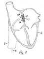
- a device as a whole designated 1 is used for introducing and placing or applying an object 2, in the embodiment of a closure for a non-intentional opening 3 between the left and right atrial chamber of the heart 4, but could also be used to place or apply another object in the Inside a blood vessel, for example, for supplying a vascular support or a mechanical blood filter or cage or the like are used.
- An essential part of the device 1 is a supply catheter 5, which is formed substantially as a tube or optionally as a tube and whose distal end 5a opens according to Figure 2 in the use position at the point where the object 2 is to be placed and applied.
- the device 1 includes an insertion device, not shown in the figures, with which the supply catheter 5 from the outside into a leading to the heart 4 blood vessel 6 is inserted.
- Figure 1 can be seen hinted a point 7 on a human body 8, where the entry of the catheter 5 takes place in a corresponding blood vessel 6.
- a corresponding insertion device can be provided at this point.
- a receptacle 9 is provided for the object 2, which receives this object 2 completely in and encloses the long sides, as shown in Figures 4 and 7.
- this receptacle 9 in the interior of the catheter or tube 5 is displaced to its distal end 5a, that is, this receptacle 9 serves as a means of transport or transport vessel for the object 2, for example an ASD closure, as in Fig.2 is shown.
- the receptacle 9 has an opening or exit for pushing out or ejecting the object 2, as shown in FIG.
- the article 2 can be displaced within the receptacle 9 through the supply catheter 5 to its distal end 5a, without even with the inside of the delivery catheter 5 in contact get.
- no particles from this inside of the tube or catheter 5 can be abraded by the article 2 and brought into the bloodstream.
- the receptacle 9 is designed to include the object 2 as a sleeve with a closed wall, so that a compressed object 2 completely separated from the inside of the guide catheter 5 remains. This serving as a receptacle 9 sleeve and its inner longitudinal cavity thus serve to accommodate the article 2 during its transport to the distal end 5a of the catheter 5 out.
- the catheter tube 5 may be made of metal and flexibly flexible.
- the catheter tube 5 has slots 10 which extend in the circumferential direction and are spaced apart from one another and which in both exemplary embodiments (FIGS. 8 to 10 on the one hand and FIGS. It can be seen in Figures 8 and 9, that these slots 10 may be connected to an approximately helically extending slot, while they are formed according to Figure 11 to 13 as individual slots. In any case, this results in a greater flexibility of the catheter or tube 5 in particular if it consists of metal.
- this slotted catheter 5 can not be stretched by the sleeve-shaped receptacle 9 and its displacement in the longitudinal direction, this slotted tube 5 in the embodiments along its extension a stabilizing strip 11 in particular of metal, which is connected to the tube 5, for example, welded.
- the stop 13 is designed as a circumferential ring on the end face of the tube or catheter 5, whose inner opening coincides with the inner cross section of the sleeve-shaped receptacle 2, so that the object 2 can be moved through this annular stop 13 smoothly and unhindered. In this case, this stop 13 forms virtually the mouth of the tube or catheter 5 and is attached to the front side of the catheter 5.
- this indirectly attacking slide or stylet 14 which projects beyond the proximal end of the catheter 5 and thus allows a corresponding handling and sliding movement relative to the catheter 5.
- this slide or stylet 14 or pusher also serves to push out the object 2 from the receptacle 9, after it has reached the stop 13, as illustrated especially Fig.5.
- the object 2 according to Figure 7 and according to the Fig.4 and 5 initially releasably connected to the stylet 14, for example via a threaded connection 15.
- the threaded connection 15 can be solved between stylet 14 and object 2, namely, if this has its desired exact position, so that then the stylet or pusher 14 can be withdrawn.
- serving as a receptacle 9 sleeve in turn has a flexible wall and the example of the existing metal hose or catheter 5 and this sleeve-shaped receptacle 9 each have a wall thickness of a little less or a little more or even exactly 1/10 mm, which results in a space-saving arrangement.
- the stylet or pusher 14 can act indirectly on the receptacle 9, namely by acting on the object 9 located in the receptacle 9, whereby nevertheless first the receptacle 9 is displaced until it reaches the abutment 13, because the friction between the sleeve-shaped receptacle 9 and the catheter tube 5 is less than the friction between the object 2 and this receptacle 9, in which the object 2 is usually housed under a certain pressure.
- the device 1 is used for applying an object 2 inside the body, for example for inserting a closure into an unwanted opening 3 between the left and the right atrial chamber of a heart 4.
- it has a supply catheter 5, the distal end 5a at the location opens, so is moved to the point at which the object 2 is to be placed or applied.
- an insertion device serves to introduce the catheter 5 from the outside into a blood vessel 6. So that when moving the article 2 or closure on the inside of the catheter 5 no particles can be dissolved and introduced into the bloodstream, the device 1 comprises a receptacle 9 or sleeve for grasping or receiving the article 2, wherein the article 2 through the catheter 5 can be transported and pushed without coming into contact with the inside of the catheter or tube 5.
Abstract
Description
Die Erfindung betrifft eine Vorrichtung zum Einbringen und Platzieren oder Applizieren eines Gegenstandes im Inneren eines Blutgefäßes oder des Herzens, beispielsweise zum Zuführen einer Gefäßstütze (stent) oder eines mechanischen Blutfilters oder Käfigs oder eines Verschlusses für eine nicht gewollte Öffnung zwischen der linken und der rechten Vorhofkammer des Herzens, mit einem Zuführkatheter, der im wesentlichen als Schlauch ausgebildet ist und dessen distales Ende in Gebrauchsstellung an der Stelle mündet, wo der Gegenstand platziert werden soll, und mit einer Einführvorrichtung, mit welcher der Katheter von Außen in ein Blutgefäß einführbar ist.The invention relates to a device for introducing and placing or applying an article inside a blood vessel or the heart, for example for supplying a stent or a mechanical blood filter or cage or a closure for an unwanted opening between the left and the right atrial chamber of the heart, with a delivery catheter, which is formed substantially as a tube and whose distal end opens in the position of use at the point where the object is to be placed, and with an insertion device, with which the catheter is inserted from the outside into a blood vessel.
Derartige Vorrichtungen sind aus der Praxis bekannt und haben sich vor allem in den Fällen bewährt, in denen ein beispielsweise aus einem Nitinolgeflecht bestehender ASD-Verschluss in das Herz eingeführt und dort platziert werden muss. Dabei ist es üblich, dass der Zuführkatheter aus einem biegsamen Kunststoffrohr besteht, durch welches der ASD-Verschluss verschoben und an seinen Bestimmungsort gebracht wird.Such devices are known in practice and have proven particularly in those cases in which an existing example of a Nitinolgeflecht ASD closure must be inserted into the heart and placed there. It is common that the delivery catheter consists of a flexible plastic tube through which the ASD closure is displaced and brought to its destination.
Dabei hat sich gezeigt, dass die Gefahr besteht, dass der Gegenstand, insbesondere wenn er aus einem Metallgeflecht besteht, bei dieser Verschiebung an der Innenseite des Kunststoffrohres Partikel ablöst oder abreibt, die in die Blutbahn und in das Herz eingetragen werden könnten.It has been found that there is a risk that the object, in particular if it consists of a metal mesh, in this displacement on the inside of the plastic tube peels off or rubs particles that could be entered into the bloodstream and into the heart.
Aus
Es besteht deshalb die Aufgabe, eine Vorrichtung der eingangs genannten Art zu schaffen, mit welcher vermieden werden kann, dass ein Gegenstand, beispielsweise ein ASD-Verschluss, bei seiner Beförderung durch den Zuführkatheter von dessen Innenseite Partikel abreibt und/oder mitnimmt.It is therefore an object to provide a device of the type mentioned above, with which it can be avoided that an article, for example an ASD closure, abrades and / or entrains particles when it is transported through the delivery catheter from its inside.
Zur Lösung dieser Aufgabe ist die eingangs definierte Vorrichtung dadurch gekennzeichnet, dass in dem Katheter eine Aufnahme für den Gegenstand vorgesehen ist, die im Inneren des Katheters oder Schlauches bis zu dessen distalem Ende verschiebbar ist, dass die Aufnahme zum Umfassen des Gegenstandes oder hülsenförmig ausgebildet ist und ihre Innenlängshöhlung zur Unterbringung des Gegenstandes während seines Transports zu dem distalen Ende des Katheters dient und dass die Aufnahme an ihrem distalen Ende eine Öffnung oder einen Ausgang zum Ausschieben oder Ausgeben des Gegenstands aus dieser Aufnahme aufweist.To solve this problem, the initially defined device is characterized in that a receptacle for the object is provided in the catheter, which is displaceable in the interior of the catheter or tube to its distal end, that the receptacle for embracing the article or sleeve-shaped and its inner longitudinal cavity serves to accommodate the article during its transport to the distal end of the catheter, and the receptacle has at its distal end an opening or exit for pushing out or dispensing the article from that receptacle.
Auf diese Weise kann vermieden werden, dass der einzubringende Gegenstand während seines Transports durch den Zuführkatheter mit dessen Innenseite Berührung hat, so dass er keine Partikel davon ablösen kann und auch von ihm selbst keine Partikel abgerieben werden können. Die Aufnahme kann als Transportgefäß durch den Zuführkatheter beziehungsweise durch den Katheterschlauch verschoben werden und mit dessen Innenseite in Berührung treten, gelangt aber nicht in den Körper, so dass selbst dann, wenn durch diese Verschiebung der Aufnahme innerhalb des Katheters Partikel gelöst werden sollten, diese nicht in den Körper, in die Blutbahn oder gar in das Herz geraten können.In this way it can be avoided that the object to be introduced has contact during its transport through the supply catheter with its inner side, so that it can not detach particles from it and even by itself no particles can be abraded. The receptacle can be moved as a transport vessel through the delivery catheter or through the catheter tube and come into contact with the inside, but does not enter the body, so that even if this release of the recording within the catheter particles should be solved, this not into the body, into the bloodstream or even into the heart.
Vor allem eine hülsenförmige und somit eine geschlossene Wandung aufweisende Aufnahme ist günstig, weil die Trennung des einzuführenden Gegenstands von der Innenseite des Katheterschlauches dadurch besonders gut sichergestellt ist.Above all, a sleeve-shaped and thus a closed wall having receptacle is favorable, because the separation of the object to be introduced from the inside of the catheter tube is thereby particularly well ensured.
Der Katheterschlauch kann aus Metall bestehen und flexibel biegsam ausgebildet sein. Dadurch kann noch besser vermieden werden, dass sich von der Innenseite des Katheters Teile oder Partikel lösen, denn Metall hat eine hohe Festigkeit auch gegen Abrieb, so dass die als Transportgefäß dienende Aufnahme erst recht bei der Bewegung durch diesen metallischen Katheterschlauch beziehungsweise das flexible Metallrohr keine Partikel davon ablösen kann.The catheter tube may be made of metal and flexibly flexible. As a result, it is even easier to prevent parts or particles from detaching themselves from the inside of the catheter, because metal has a high resistance to abrasion, so that the receptacle serving as a transport vessel does not change any more during the movement through this metallic catheter tube or the flexible metal tube Particles can replace it.
Für eine gute Flexibilität des Katheters ist es zweckmäßig, wenn der Katheterschlauch in Umfangsrichtung verlaufende und zueinander beabstandete Schlitze aufweist, die insbesondere parallel zueinander angeordnet sind, wobei sie zu einem etwa schraubenlinienförmig verlaufenden Schlitz verbunden oder als Einzelschlitze ausgebildet sein können. Ein derartig gestalteter Katheter kann besonders gut an unterschiedlichste Biegungen oder Krümmungen von Blutgefäßen angepasst werden.
Dabei kann eine ausreichende oder verbesserte Festigkeit des Katheters dadurch erzielt werden, dass der geschlitzte Schlauch oder Metallschlauch wenigstens einen entlang seiner Erstreckung verlaufenden Stabilisierungsstreifen, insbesondere aus Metall, aufweist, der mit dem Schlauch verbunden, insbesondere verschweißt ist. Bevorzugt ist dabei eine Anordnung dieses Stabilisierungsstreifens an der Außenseite des Katheterschlauches. Dieser Stabilisierungsstreifen kann verhindern, dass der Katheterschlauch insbesondere im Falle von Schlitzungen eventuell in Längsrichtung verformt oder gelängt wird und durch die durch ihn hindurch bewegte Aufnahme beziehungsweise das Transportgefäß in ungewollter Weise verformt werden kann.For a good flexibility of the catheter, it is expedient if the catheter tube has circumferentially extending and mutually spaced slots, which are in particular arranged parallel to each other, wherein they can be connected to an approximately helically extending slot or formed as individual slots. Such a designed catheter can be particularly good at a variety of Bends or bends of blood vessels can be adjusted.
In this case, a sufficient or improved strength of the catheter can be achieved in that the slotted tube or metal tube has at least one extending along its extension stabilizing strips, in particular of metal, which is connected to the hose, in particular welded. An arrangement of this stabilizing strip on the outside of the catheter tube is preferred. This stabilizing strip can prevent the catheter tube, in particular in the case of slits, from being deformed or lengthened in the longitudinal direction and can be deformed in an unintentional manner by the receptacle or transport container moving therethrough.
Für eine möglichst einfache Abgabe des transportierten Gegenstands kann am distalen Ende des Katheterschlauches ein sich radial nach Innen erstreckender Anschlag für die Aufnahme vorgesehen sein. Somit wird sichergestellt, dass die Aufnahme oder das sie bildende Transportgefäß für den zu applizierenden Gegenstand nicht versehentlich aus dem Katheterschlauch herausgeschoben werden kann.For the simplest possible delivery of the transported object can be provided at the distal end of the catheter tube, a radially inwardly extending stop for the recording. This ensures that the receptacle or the transport vessel forming it for the object to be applied can not be accidentally pushed out of the catheter tube.
Dabei kann der Anschlag als an der Stirnseite oder am Innenumfang des Schlauches oder Katheters umlaufender Vorsprung oder Ring ausgebildet sein. Somit wird die Aufnahme zuverlässig an diesem Anschlag angehalten, so dass danach der zu implantierende oder zu applizierende Gegenstand aus ihr herausgeschoben werden kann, wodurch er gleichzeitig auch den Katheterschlauch verlässt.In this case, the stop may be formed as a projection or ring encircling the front or on the inner circumference of the tube or catheter. Thus, the recording is reliably stopped at this stop, so that afterwards the object to be implanted or applied can be pushed out of it, whereby he leaves the catheter tube at the same time.
Der Anschlag kann mit der Mündung des Schlauches oder Katheters bündig sein oder diese Mündung bilden. Somit gelangt das distale Ende der Aufnahme soweit wie möglich an das distale Ende des Katheterschlauches.The stop may be flush with the mouth of the tube or catheter or form this mouth. Thus reaches the distal end of the recording as far as possible to the distal end of the catheter tube.
Für eine möglichst einfache Abgabe des transportierten Gegenstandes kann zur Verschiebung der Aufnahme ein an dieser direkt oder indirekt angreifender Schieber oder Mandrin vorgesehen sein und dieser Schieber oder Mandrin kann vorzugsweise auch zum Ausschieben des Gegenstands aus der Aufnahme nach Erreichen des Anschlages dienen.For the simplest possible delivery of the transported object can be provided for shifting the recording on this directly or indirectly attacking slider or stylet and this slide or stylet can preferably also serve to push out the object from the receptacle after reaching the stop.
Dabei kann der Mandrin mit dem Gegenstand lösbar verbunden oder verschraubt sein. Somit kann der Verschiebevorgang während des Transports dadurch erfolgen, dass der mit dem Gegenstand lösbar verbundene Mandrin innerhalb des Schlauches vorgeschoben wird, wodurch gleichzeitig die den Gegenstand enthaltende Aufnahme verschoben wird, bis sie den Anschlag erreicht. Eine weitere Schiebebewegung verursacht dann das Ausschieben des Gegenstands aus der Aufnahme beziehungsweise aus dem Transportgefäß und damit auch aus dem Katheterschlauch. Dabei ist günstig, dass die Reibung zwischen dem Gegenstand und seiner Aufnahme größer als zwischen dieser Aufnahme und dem Katheterschlauch ist.In this case, the stylet can be releasably connected or screwed to the object. Thus, the shifting operation during transport can be carried out by advancing the stylet detachably connected to the object within the tube, whereby at the same time the receptacle containing the object is displaced until it reaches the stop. Another sliding movement then causes the expulsion of the object from the receptacle or from the transport vessel and thus also from the catheter tube. It is favorable that the friction between the article and its recording is greater than between this recording and the catheter tube.
Damit die Aufnahme auch Krümmungen und Biegungen gut folgen kann, kann die als Aufnahme dienende Hülse eine flexible Wandung haben.Thus, the recording can also follow bends and bends well, serving as a receptacle sleeve can have a flexible wall.
Versuche haben gezeigt, dass es günstig ist, wenn der insbesondere aus Metall bestehende Schlauch des Katheters und/oder die insbesondere hülsenförmige Aufnahme eine Wandstärke von etwa 1/10 mm oder weniger oder etwas mehr haben. Dies ergibt eine verringerte Außenabmessung des Katheterschlauches gegenüber einem Kunststoffschlauch oder erlaubt einen größeren Innenquerschnitt, um einen entsprechend größeren Gegenstand transportieren zu können.Experiments have shown that it is favorable if the tube of the catheter, in particular of metal, and / or the in particular sleeve-shaped receptacle have a wall thickness of about 1/10 mm or less or somewhat more. This results in a reduced outer dimension of the catheter tube relative to a plastic tube or allows a larger inner cross-section to transport a correspondingly larger object can.
Falls erforderlich, können noch besondere Maßnahmen getroffen sein, um die Reibung zwischen der insbesondere hülsenförmigen Aufnahme und dem Katheterschlauch geringer als zwischen dem Gegenstand und der Aufnahme zu machen. Da jedoch der Gegenstand in der Aufnahme in der Regel zusammengedrückt ist, ergibt sich schon dadurch ein größerer Widerstand dieses Gegenstands gegen sein Herausschieben aus der Aufnahme gegenüber dem Widerstand, den die Aufnahme beim Verschieben innerhalb des Katheterschlauches leistet. Somit bedarf es in der Regel keiner besonderen Maßnahmen, um den Gegenstand in der hülsenförmigen Aufnahme genügend festzulegen, bis diese das distale Ende des Katheterschlauches erreicht hat.If necessary, special measures can be taken to make the friction between the particular sleeve-shaped receptacle and the catheter tube less than between the object and the recording. However, since the object is usually compressed in the recording, this results in a greater resistance of this object against his pushing out of the receptacle against the resistance, which makes the recording when moving within the catheter tube. Thus, as a rule, no special measures are required to adequately fix the article in the sleeve-shaped receptacle until it has reached the distal end of the catheter tube.
Nachstehend sind Ausführungsbeispiele der Erfindung anhand der Zeichnung näher beschrieben. Es zeigt in zum Teil schematisierter Darstellung:
- Fig. 1
- einen in ein Blutgefäß eingeführten und bis in den Bereich der Vorhofkammern des Herzens vorgeschobenen Zuführkatheter, mit welchem ein Gegenstand zum Verschließen einer ungewollten Öffnung zwischen der linken und der rechten Vorhofkammer des Herzens einführbar ist,
- Fig. 2
- in vergrößertem Maßstab einen Längsschnitt des Herzens mit einer ungewollten Öffnung im Septum zwischen der linken und der rechten Vorhofkammer, nachdem in diese Öffnung ein ASD-Verschluss eingefügt ist, der durch den Katheterschlauch zugeführt wurde und noch mit einem zum Ausschieben aus dem Schlauch dienenden Mandrin oder Pusher verbunden ist,
- Fig. 3
- eine Seitenansicht des Katheters, an dessen proximalen Ende der Mandrin vorsteht,
- Fig. 4
- in vergrößertem Maßstab das in Fig.3 durch einen Kreis markierte distale Ende des Katheterschlauches im Längsschnitt, wobei im Inneren des Katheterschlauches eine verschiebbare Aufnahme als Transportgefäß erkennbar ist, die den zu platzierenden Gegenstand in zusammengedrückter Form enthält,
- Fig. 5
- eine der Fig.4 entsprechende Darstellung, wobei die Aufnahme einen am distalen Ende des Zuführkatheters befindlichen Anschlag erreicht hat, der ringförmig ausgebildet ist und eine Innenöffnung aufweist, die etwa bündig mit der Innenöffnung der Aufnahme ist, so dass der Gegenstand mit Hilfe des Mandrins - wie dargestellt - durch weitere Vorwärtsbewegung des Mandrins ausschiebbar ist, bis der Gegenstand die in Fig.2 dargestellte Position erreicht hat und sich dort beispielsweise aufgrund seiner Fertigung aus Memory-Material zu einem ASD-Verschluss formt,
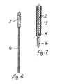
- Fig. 6
- den Mandrin oder Pusher mit dem zu transportierenden Gegenstand sowie
- Fig. 7
- in vergrößertem Maßstab den Mandrin, den zu transportierenden Gegenstand und deren gegenseitige lösbare Verbindung mit Hilfe eines Gewindes, wobei der Gegenstand in der Aufnahme angeordnet ist, die innerhalb des Führungskatheters oder Zuführkatheters verschiebbar ist,
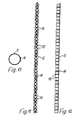
- Fig. 8
- eine erste Seitenansicht und
- Fig. 9
- eine zweite Seitenansicht eines Zuführkatheters, der zur Vergrößerung seiner Flexibilität mit parallelen, zweckmäßigerweise schraubenlinienförmig verlaufenden Schlitzen versehen und außenseitig durch einen in Längserstreckungsrichtung verlaufenden Streifen stabilisiert ist,
- Fig. 10
- im vergrößertem Maßstab einen Querschnitt des Zuführkatheters gemäß Fig.8 und 9,
- Fig. 11
- eine erste Seitenansicht und
- Fig. 12
- eine zweite Seitenansicht einer abgewandelten Ausführungsform des Zuführkatheters, welcher mit etwa in Umfangsrichtung verlaufenden parallelen Schlitzen quer zu seiner Längsmittelachse versehen ist, wobei die durch diese Schlitze voneinander getrennten Abschnitte des Zuführkatheters durch wenigstens einen in Längserstreckungsrichtung verlaufenden, mit ihnen verbundenen oder verschweißten Stabilisierungsstreifen verbunden sind, sowie
- Fig. 13
- in vergrößertem Maßstab einen Querschnitt des Zuführkatheters gemäß den Fig.11 und 12.
- Fig. 1
- a delivery catheter inserted into a blood vessel and advanced into the region of the atrial chambers of the heart, with which an article for closing an unwanted opening between the left and right atrial chambers of the heart is insertable,
- Fig. 2
- on an enlarged scale, a longitudinal section of the heart with an unwanted opening in the septum between the left and right atrial chamber, after in this opening an ASD-closure is inserted, which was supplied through the catheter tube and still serving with a pushing out of the tube stylet or Pusher is connected,
- Fig. 3
- a side view of the catheter, protruding at the proximal end of the stylet,
- Fig. 4
- in an enlarged scale, the marked in Figure 3 by a circle distal end of the catheter tube in longitudinal section, wherein in the interior of the catheter tube a displaceable receptacle is visible as a transport vessel containing the object to be placed in compressed form,
- Fig. 5
- 4 corresponding representation, wherein the receptacle has reached a located at the distal end of the delivery catheter stop which is annular and has an inner opening which is approximately flush with the inner opening of the receptacle, so that the object by means of the stylet - as shown - can be pushed out by further forward movement of the stylet until the object has reached the position shown in Figure 2 and forms there, for example, due to its production of memory material to form an ASD closure,
- Fig. 6
- the stylet or pusher with the object to be transported as well
- Fig. 7
- on an enlarged scale the stylet, the object to be transported and their mutual detachable connection by means of a thread, wherein the object is arranged in the receptacle, which is displaceable within the guide catheter or delivery catheter,
- Fig. 8
- a first side view and
- Fig. 9
- a second side view of a delivery catheter, which is provided to increase its flexibility with parallel, suitably helically extending slots and the outside is stabilized by a running in the longitudinal direction strip,
- Fig. 10
- on an enlarged scale, a cross-section of the delivery catheter according to Figures 8 and 9,
- Fig. 11
- a first side view and
- Fig. 12
- a second side view of a modified embodiment of the delivery catheter, which is provided with approximately circumferentially extending parallel slots transverse to its longitudinal central axis, wherein the separated by these slots portions of the delivery catheter by at least one extending in the longitudinal direction, connected to them or welded stabilization strips, such as
- Fig. 13
- on an enlarged scale, a cross section of the delivery catheter according to the Figures 11 and 12th
Eine im Ganzen mit 1 bezeichnete Vorrichtung dient zum Einbringen und Platzieren oder Applizieren eines Gegenstands 2, im Ausführungsbeispiel eines Verschlusses für eine nicht gewollte Öffnung 3 zwischen der linken und der rechten Vorhofkammer des Herzens 4, könnte aber auch zum Platzieren oder Applizieren eines anderen Gegenstandes im Inneren eines Blutgefäßes, zum Beispiel zum Zuführen einer Gefäßstütze oder eines mechanischen Blutfilters oder Käfigs oder dergleichen dienen.A device as a whole designated 1 is used for introducing and placing or applying an
Ein wesentlicher Teil der Vorrichtung 1 ist ein Zuführkatheter 5, der im wesentlichen als Schlauch oder gegebenenfalls als Rohr ausgebildet ist und dessen distales Ende 5a gemäß Fig.2 in Gebrauchsstellung an der Stelle mündet, wo der Gegenstand 2 platziert und appliziert werden soll. Ferner gehört zu der Vorrichtung 1 eine in den Figuren nicht dargestellte Einführvorrichtung, mit welcher der Zuführkatheter 5 von außen in ein zu dem Herzen 4 führendes Blutgefäß 6 einführbar ist. In Fig.1 erkennt man andeutungsweise eine Stelle 7 an einem menschlichen Körper 8, wo der Eintritt des Katheters 5 in ein entsprechendes Blutgefäß 6 erfolgt. In bekannter Weise kann an dieser Stelle eine entsprechende Einführvorrichtung vorgesehen werden.An essential part of the
In den Fig.4 und 5 ist dargestellt, dass in dem Katheter 5, im Folgenden auch als "Schlauch 5" bezeichnet, eine Aufnahme 9 für den Gegenstand 2 vorgesehen ist, die diesen Gegenstand 2 vollständig in sich aufnimmt und an den Längsseiten umschließt, wie es die Fig.4 und 7 zeigen.4 and 5 it is shown that in the
Gemäß den Fig.4 und 5 ist diese Aufnahme 9 im Inneren des Katheters oder Schlauches 5 bis zu dessen distalem Ende 5a verschiebbar, dass heißt diese Aufnahme 9 dient als Transportmittel oder Transportgefäß für den Gegenstand 2, beispielsweise einen ASD-Verschluss, wie er in Fig.2 dargestellt ist.According to Figures 4 and 5, this
An ihrem distalen Ende hat die Aufnahme 9 eine Öffnung oder einen Ausgang zum Ausschieben oder Ausgeben des Gegenstands 2, wie es in Fig.5 dargestellt ist. Somit kann also der Gegenstand 2 innerhalb der Aufnahme 9 durch den Zuführkatheter 5 bis zu dessen distalen Ende 5a hin verschoben werden, ohne selbst mit der Innenseite des Zuführkatheters 5 in Berührung zu kommen. Somit können keine Partikel von dieser Innenseite des Schlauches oder Katheters 5 durch den Gegenstand 2 abgerieben und in die Blutbahn gebracht werden.At its distal end, the
Die Aufnahme 9 ist dabei zum Umfassen des Gegenstands 2 als Hülse mit geschlossener Wandung ausgebildet, damit auch ein zusammengedrückter Gegenstand 2 vollständig von der Innenseite des Führungskatheters 5 getrennt bleibt. Diese als Aufnahme 9 dienende Hülse und ihre Innenlängshöhlung dienen also zur Unterbringung des Gegenstands 2 während seines Transports zu dem distalen Ende 5a des Katheters 5 hin.The
Der Katheterschlauch 5 kann aus Metall bestehen und flexibel biegsam ausgebildet sein.The
In den Ausführungsbeispielen gemäß Fig.8 bis 13 weist der Katheterschlauch 5 in Umfangsrichtung verlaufende und zueinander beabstandete Schlitze 10 auf, die in beiden Ausführungsbeispielen (Fig.8 bis 10 einerseits und Fig.11 bis 13 andererseits) parallel zueinander angeordnet sind beziehungsweise verlaufen. Dabei erkennt man in Fig.8 und 9, dass diese Schlitze 10 zu einem etwa schraubenlinienförmig verlaufenden Schlitz verbunden sein können, während sie gemäß Fig.11 bis 13 als Einzelschlitze ausgebildet sind. In jedem Falle ergibt sich dadurch eine größere Flexibilität des Katheters oder Schlauches 5 insbesondere, wenn er aus Metall besteht.In the exemplary embodiments according to FIGS. 8 to 13, the
Damit dieser geschlitzte Katheter 5 nicht durch die hülsenförmige Aufnahme 9 und deren Verschiebung in Längsrichtung gedehnt werden kann, weist dieser geschlitzte Schlauch 5 in den Ausführungsbeispielen entlang seiner Erstreckung einen Stabilisierungsstreifen 11 insbesondere aus Metall auf, der mit dem Schlauch 5 verbunden, beispielsweise verschweißt ist.So that this slotted
Dabei erkennt man in Fig.8 über die gesamte Länge drei Schweißpunkte 12, während gemäß Fig.11 jeder einzelne Abschnitt des Schlauches 5 mit dem Stabilisierungsstreifen 11 über einen solchen Schweißpunkt 12 verbunden ist, weil die Schlitze 10 über den Gesamtumfang des Katheters 5 verlaufen.It can be seen in Figure 8 over the entire length of three
In den Fig.4 und 5 erkennt man, dass am distalen Ende 5a des Katheterschlauches 5 ein sich radial nach innen erstreckender Anschlag 13 für die Aufnahme 9 vorgesehen ist, die gemäß Fig. 5 mit ihrem distalen Ende an dem Anschlag 13 gegen ein Ausschieben aus dem distalen Ende 5a des Katheters 5 gehindert wird, so dass bei einem weiteren Schiebevorgang dann der Gegenstand 2 sowohl aus der Aufnahme 9 als auch aus dem Katheter 5 ausgeschoben werden kann.4 and 5 it can be seen that at the
Der Anschlag 13 ist dabei als an der Stirnseite des Schlauches oder Katheters 5 umlaufender Ring ausgebildet, dessen Innenöffnung mit dem Innenquerschnitt der hülsenförmigen Aufnahme 2 übereinstimmt, so dass der Gegenstand 2 glatt und ungehindert durch diesen ringförmigen Anschlag 13 hindurch bewegt werden kann. Dabei bildet dieser Anschlag 13 praktisch die Mündung des Schlauches oder Katheters 5 und ist an der Stirnseite des Katheters 5 befestigt.The
Zum Verschieben der Aufnahme 9 ist ein an dieser indirekt angreifender Schieber oder Mandrin 14 vorgesehen, der das proximale Ende des Katheters 5 überragt und so eine entsprechende Handhabung und Schiebebewegung relativ zum Katheter 5 ermöglicht. Dabei dient dieser Schieber oder Mandrin 14 oder Pusher auch zum Ausschieben des Gegenstandes 2 aus der Aufnahme 9, nachdem diese den Anschlag 13 erreicht hat, wie es vor allem Fig.5 verdeutlicht.To move the
Dabei ist der Gegenstand 2 gemäß Fig.7 sowie gemäß den Fig.4 und 5 zunächst mit dem Mandrin 14 lösbar verbunden, beispielsweise über eine Gewindeverbindung 15. Dadurch ist es möglich, den Gegenstand 2 gemäß Fig.5 auszuschieben und bis an die Stelle zu bewegen, wo er platziert werden soll, also beispielsweise in eine nicht gewollte Öffnung 3 zwischen der linken und der rechten Vorhofkammer des Herzens 4, wo sich der Gegenstand 2 aus seiner zunächst zusammengedrückten und von der Aufnahme oder Hülse 9 begrenzten Form in seine endgültige gewollte Form als Verschluss entfalten kann, der dann die Öffnung 3 verschließt. Danach kann die Gewindeverbindung 15 zwischen Mandrin 14 und Gegenstand 2 gelöst werden, wenn dieser nämlich seine gewünschte genaue Position hat, so dass dann der Mandrin oder Pusher 14 zurückgezogen werden kann.In this case, the
Es sei noch erwähnt, dass die als Aufnahme 9 dienende Hülse ihrerseits eine flexible Wandung hat und das beispielsweise der aus Metall bestehende Schlauch oder Katheter 5 und auch diese hülsenförmige Aufnahme 9 jeweils eine Wandstärke von etwas weniger oder etwas mehr oder auch genau von 1/10 mm haben können, was eine platzsparende Anordnung ergibt.It should be mentioned that serving as a
Es wurde schon erwähnt, dass der Mandrin oder Pusher 14 indirekt an der Aufnahme 9 angreifen kann, indem er nämlich an dem in der Aufnahme 9 befindlichen Gegenstand 2 angreift, wobei dennoch zunächst auch die Aufnahme 9 verschoben wird, bis sie den Anschlag 13 erreicht, weil die Reibung zwischen der hülsenförmigen Aufnahme 9 und dem Katheterschlauch 5 geringer ist als die Reibung zwischen dem Gegenstand 2 und dieser Aufnahme 9, in welcher der Gegenstand 2 in der Regel auch unter einem gewissen Druck untergebracht ist.It has already been mentioned that the stylet or
Denkbar wäre eventuell aber auch, dass unmittelbar an der Aufnahme 9 ein entsprechend gestalteter schlauchförmiger Pusher angreift, in dessen Inneren ein weiterer Pusher oder Mandrin zum Ausschieben des Gegenstands 2 verlaufen könnte.It would also be conceivable, however, that directly on the receptacle 9 a suitably shaped tubular pusher attacks, in the interior of another pusher or Mandrin to push out the
Die Vorrichtung 1 dient zum Applizieren eines Gegenstandes 2 im Inneren des Körpers, beispielsweise zum Einsetzen eines Verschlusses in eine ungewollte Öffnung 3 zwischen der linken und der rechten Vorhofkammer eines Herzens 4. Dazu weist sie einen Zuführkatheter 5 auf, dessen distales Ende 5a an der Stelle mündet, also zu der Stelle hin verschoben wird, an welcher der Gegenstand 2 platziert oder appliziert werden soll. In üblicher Weise dient eine Einführvorrichtung dazu, den Katheter 5 von außen in ein Blutgefäß 6 einzuführen. Damit beim Verschieben des Gegenstands 2 oder Verschlusses an der Innenseite des Katheters 5 keine Partikel gelöst und in den Blutkreislauf eingetragen werden können, weist die Vorrichtung 1 eine Aufnahme 9 oder Hülse zum Umfassen oder Aufnehmen des Gegenstands 2 auf, worin der Gegenstand 2 durch den Katheter 5 transportiert und geschoben werden kann, ohne mit der Innenseite des Katheters oder Schlauches 5 in Berührung zu gelangen.The
Claims (12)
Applications Claiming Priority (1)
| Application Number | Priority Date | Filing Date | Title |
|---|---|---|---|
| DE102005022423A DE102005022423B3 (en) | 2005-05-14 | 2005-05-14 | Device for introducing an article inside a blood vessel or the heart |
Publications (2)
| Publication Number | Publication Date |
|---|---|
| EP1723937A1 true EP1723937A1 (en) | 2006-11-22 |
| EP1723937B1 EP1723937B1 (en) | 2009-01-14 |
Family
ID=36658815
Family Applications (1)
| Application Number | Title | Priority Date | Filing Date |
|---|---|---|---|
| EP06009296A Not-in-force EP1723937B1 (en) | 2005-05-14 | 2006-05-05 | Device for delivering an object into a blood vessel or into the heart |
Country Status (4)
| Country | Link |
|---|---|
| US (1) | US20060259121A1 (en) |
| EP (1) | EP1723937B1 (en) |
| AT (1) | ATE420613T1 (en) |
| DE (2) | DE102005022423B3 (en) |
Cited By (1)
| Publication number | Priority date | Publication date | Assignee | Title |
|---|---|---|---|---|
| EP3549557A1 (en) | 2018-04-04 | 2019-10-09 | Biotronik AG | Structure for a catheter sleeve and catheter sleeve |
Families Citing this family (13)
| Publication number | Priority date | Publication date | Assignee | Title |
|---|---|---|---|---|
| DE102006035191B4 (en) * | 2006-07-29 | 2009-05-14 | Osypka, Peter, Dr. Ing. | Medical device |
| WO2008055301A1 (en) | 2006-11-07 | 2008-05-15 | Univ Sydney | Devices and methods for the treatment of heart failure |
| US20110257723A1 (en) | 2006-11-07 | 2011-10-20 | Dc Devices, Inc. | Devices and methods for coronary sinus pressure relief |
| US9232997B2 (en) | 2006-11-07 | 2016-01-12 | Corvia Medical, Inc. | Devices and methods for retrievable intra-atrial implants |
| US10413284B2 (en) | 2006-11-07 | 2019-09-17 | Corvia Medical, Inc. | Atrial pressure regulation with control, sensing, monitoring and therapy delivery |
| WO2010065488A2 (en) * | 2008-12-01 | 2010-06-10 | Tengiz Tkebuchava | Multifunctional cardiac pacemaker system |
| US9757107B2 (en) | 2009-09-04 | 2017-09-12 | Corvia Medical, Inc. | Methods and devices for intra-atrial shunts having adjustable sizes |
| CN102905626A (en) | 2010-01-29 | 2013-01-30 | Dc设备公司 | Devices and systems for treating heart failure |
| US9277995B2 (en) | 2010-01-29 | 2016-03-08 | Corvia Medical, Inc. | Devices and methods for reducing venous pressure |
| CN107334512B (en) | 2011-02-10 | 2021-04-13 | 可维亚媒体公司 | Device for creating and maintaining an intra-atrial pressure relief opening |
| US9205236B2 (en) | 2011-12-22 | 2015-12-08 | Corvia Medical, Inc. | Methods, systems, and devices for resizable intra-atrial shunts |
| US10675450B2 (en) | 2014-03-12 | 2020-06-09 | Corvia Medical, Inc. | Devices and methods for treating heart failure |
| JP6799526B2 (en) | 2014-07-23 | 2020-12-16 | コルヴィア メディカル インコーポレイテッド | Equipment and methods for the treatment of heart failure |
Citations (4)
| Publication number | Priority date | Publication date | Assignee | Title |
|---|---|---|---|---|
| WO1993011823A1 (en) * | 1991-12-12 | 1993-06-24 | Target Therapeutics, Inc. | Detachable pusher-vasoocclusion coil assembly with threaded coupling |
| EP0696447A2 (en) * | 1994-08-12 | 1996-02-14 | Cardiovascular Concepts, Inc. | Apparatus and methods for deployment release of intraluminal prostheses |
| WO1996038193A1 (en) * | 1995-05-31 | 1996-12-05 | Cardia Catheter Co. | Flexible tubular device for use in medical applications |
| US6506196B1 (en) * | 1999-06-22 | 2003-01-14 | Ndo Surgical, Inc. | Device and method for correction of a painful body defect |
Family Cites Families (5)
| Publication number | Priority date | Publication date | Assignee | Title |
|---|---|---|---|---|
| US6077295A (en) * | 1996-07-15 | 2000-06-20 | Advanced Cardiovascular Systems, Inc. | Self-expanding stent delivery system |
| US5749890A (en) * | 1996-12-03 | 1998-05-12 | Shaknovich; Alexander | Method and system for stent placement in ostial lesions |
| US6887235B2 (en) * | 1999-03-24 | 2005-05-03 | Micrus Corporation | Variable stiffness heating catheter |
| DE10012852A1 (en) * | 2000-03-16 | 2001-09-20 | Angiomed Ag | Percutaneous transluminal stent delivery system, has distal tip zone which is contiguous with distal end of tube, in which tip zone both luminal surface and abluminal surface taper radially inwardly nearer to distal end of tube |
| US6706055B2 (en) * | 2001-04-03 | 2004-03-16 | Medtronic Ave Inc. | Guidewire apparatus for temporary distal embolic protection |
-
2005
- 2005-05-14 DE DE102005022423A patent/DE102005022423B3/en not_active Expired - Fee Related
-
2006
- 2006-05-05 AT AT06009296T patent/ATE420613T1/en not_active IP Right Cessation
- 2006-05-05 DE DE502006002627T patent/DE502006002627D1/en active Active
- 2006-05-05 EP EP06009296A patent/EP1723937B1/en not_active Not-in-force
- 2006-05-12 US US11/433,492 patent/US20060259121A1/en not_active Abandoned
Patent Citations (4)
| Publication number | Priority date | Publication date | Assignee | Title |
|---|---|---|---|---|
| WO1993011823A1 (en) * | 1991-12-12 | 1993-06-24 | Target Therapeutics, Inc. | Detachable pusher-vasoocclusion coil assembly with threaded coupling |
| EP0696447A2 (en) * | 1994-08-12 | 1996-02-14 | Cardiovascular Concepts, Inc. | Apparatus and methods for deployment release of intraluminal prostheses |
| WO1996038193A1 (en) * | 1995-05-31 | 1996-12-05 | Cardia Catheter Co. | Flexible tubular device for use in medical applications |
| US6506196B1 (en) * | 1999-06-22 | 2003-01-14 | Ndo Surgical, Inc. | Device and method for correction of a painful body defect |
Cited By (1)
| Publication number | Priority date | Publication date | Assignee | Title |
|---|---|---|---|---|
| EP3549557A1 (en) | 2018-04-04 | 2019-10-09 | Biotronik AG | Structure for a catheter sleeve and catheter sleeve |
Also Published As
| Publication number | Publication date |
|---|---|
| EP1723937B1 (en) | 2009-01-14 |
| ATE420613T1 (en) | 2009-01-15 |
| DE502006002627D1 (en) | 2009-03-05 |
| DE102005022423B3 (en) | 2007-01-18 |
| US20060259121A1 (en) | 2006-11-16 |
Similar Documents
| Publication | Publication Date | Title |
|---|---|---|
| EP1723937B1 (en) | Device for delivering an object into a blood vessel or into the heart | |
| DE69724150T2 (en) | INTRODUCTION CATHETER FOR A FINAL PROSTHESIS WITH STEP-BY-STEP CONTROL | |
| DE69534167T2 (en) | DEVICE FOR TREATING BLOOD VESSELS | |
| DE69533356T2 (en) | DEVICE FOR INSERTING AND UNFOLDING INTRALUMINAL DEVICES | |
| DE69816172T2 (en) | Fluid controlled stent delivery system | |
| DE69734672T2 (en) | GALLEN CATHETER FOR REPLACEMENT BY A SINGLE OPERATOR | |
| DE69912718T2 (en) | Rheolytic thrombectomy catheter | |
| DE60119142T2 (en) | ENDOLUMINAL APPLIED VASCULAR TRANSPLANT | |
| EP0348692B1 (en) | Device for entering a vein or artery by means of a guide wire | |
| DE4406077B4 (en) | Balloon Catheter and Guidewire Arrangement | |
| DE69725324T2 (en) | Seal for a catheter device with dilatation and occlusion balloon | |
| DE60035936T2 (en) | TOOLS FOR (RE) INSERTING A GUIDE WIRE AND USE METHOD | |
| DE60213300T2 (en) | Wire with defined breaking point | |
| DE2804058B2 (en) | Medical device for removing foreign objects from a body cavity | |
| DE3623698C2 (en) | Guide wire system for guiding a catheter | |
| EP2067498A1 (en) | Catheter with catheter receptacle lumen | |
| EP0461474A1 (en) | Balloon catheter with sleeve | |
| EP1157677A2 (en) | Device for applying bone cement and cannula for such a device | |
| EP1042996A2 (en) | Stent apparatus | |
| DE4128530A1 (en) | ANESTHESIA CUTLERY | |
| EP1205209B1 (en) | Cardioplegia balloon catheter | |
| EP3383317A1 (en) | Intraocular lens cartridge comprising a lubricant feed duct, and injector comprising a cartridge | |
| DE202011101205U1 (en) | Anastomosegerät | |
| DE102006050221B3 (en) | Device for applying active substances on surfaces of medical implants, has retaining bracket at cartridge, where two cylindrical housing parts are provided, which are pluggable into each other and are sterilely sealed against each other | |
| EP0872257A2 (en) | Catheter |
Legal Events
| Date | Code | Title | Description |
|---|---|---|---|
| PUAI | Public reference made under article 153(3) epc to a published international application that has entered the european phase |
Free format text: ORIGINAL CODE: 0009012 |
|
| 17P | Request for examination filed |
Effective date: 20060902 |
|
| AK | Designated contracting states |
Kind code of ref document: A1 Designated state(s): AT BE BG CH CY CZ DE DK EE ES FI FR GB GR HU IE IS IT LI LT LU LV MC NL PL PT RO SE SI SK TR |
|
| AX | Request for extension of the european patent |
Extension state: AL BA HR MK YU |
|
| AKX | Designation fees paid |
Designated state(s): AT BE BG CH CY CZ DE DK EE ES FI FR GB GR HU IE IS IT LI LT LU LV MC NL PL PT RO SE SI SK TR |
|
| 17Q | First examination report despatched |
Effective date: 20070829 |
|
| GRAP | Despatch of communication of intention to grant a patent |
Free format text: ORIGINAL CODE: EPIDOSNIGR1 |
|
| RTI1 | Title (correction) |
Free format text: DEVICE FOR DELIVERING AN OBJECT INTO A BLOOD VESSEL OR INTO THE HEART |
|
| GRAS | Grant fee paid |
Free format text: ORIGINAL CODE: EPIDOSNIGR3 |
|
| GRAA | (expected) grant |
Free format text: ORIGINAL CODE: 0009210 |
|
| AK | Designated contracting states |
Kind code of ref document: B1 Designated state(s): AT BE BG CH CY CZ DE DK EE ES FI FR GB GR HU IE IS IT LI LT LU LV MC NL PL PT RO SE SI SK TR |
|
| REG | Reference to a national code |
Ref country code: GB Ref legal event code: FG4D Free format text: NOT ENGLISH |
|
| REG | Reference to a national code |
Ref country code: CH Ref legal event code: EP |
|
| REG | Reference to a national code |
Ref country code: CH Ref legal event code: NV Representative=s name: HANS RUDOLF GACHNANG PATENTANWALT |
|
| REG | Reference to a national code |
Ref country code: IE Ref legal event code: FG4D Free format text: LANGUAGE OF EP DOCUMENT: GERMAN |
|
| REF | Corresponds to: |
Ref document number: 502006002627 Country of ref document: DE Date of ref document: 20090305 Kind code of ref document: P |
|
| PG25 | Lapsed in a contracting state [announced via postgrant information from national office to epo] |
Ref country code: NL Free format text: LAPSE BECAUSE OF FAILURE TO SUBMIT A TRANSLATION OF THE DESCRIPTION OR TO PAY THE FEE WITHIN THE PRESCRIBED TIME-LIMIT Effective date: 20090114 |
|
| NLV1 | Nl: lapsed or annulled due to failure to fulfill the requirements of art. 29p and 29m of the patents act | ||
| PG25 | Lapsed in a contracting state [announced via postgrant information from national office to epo] |
Ref country code: SI Free format text: LAPSE BECAUSE OF FAILURE TO SUBMIT A TRANSLATION OF THE DESCRIPTION OR TO PAY THE FEE WITHIN THE PRESCRIBED TIME-LIMIT Effective date: 20090114 Ref country code: LT Free format text: LAPSE BECAUSE OF FAILURE TO SUBMIT A TRANSLATION OF THE DESCRIPTION OR TO PAY THE FEE WITHIN THE PRESCRIBED TIME-LIMIT Effective date: 20090114 Ref country code: FI Free format text: LAPSE BECAUSE OF FAILURE TO SUBMIT A TRANSLATION OF THE DESCRIPTION OR TO PAY THE FEE WITHIN THE PRESCRIBED TIME-LIMIT Effective date: 20090114 Ref country code: ES Free format text: LAPSE BECAUSE OF FAILURE TO SUBMIT A TRANSLATION OF THE DESCRIPTION OR TO PAY THE FEE WITHIN THE PRESCRIBED TIME-LIMIT Effective date: 20090425 |
|
| REG | Reference to a national code |
Ref country code: IE Ref legal event code: FD4D |
|
| PG25 | Lapsed in a contracting state [announced via postgrant information from national office to epo] |
Ref country code: IS Free format text: LAPSE BECAUSE OF FAILURE TO SUBMIT A TRANSLATION OF THE DESCRIPTION OR TO PAY THE FEE WITHIN THE PRESCRIBED TIME-LIMIT Effective date: 20090514 Ref country code: SE Free format text: LAPSE BECAUSE OF FAILURE TO SUBMIT A TRANSLATION OF THE DESCRIPTION OR TO PAY THE FEE WITHIN THE PRESCRIBED TIME-LIMIT Effective date: 20090414 Ref country code: LV Free format text: LAPSE BECAUSE OF FAILURE TO SUBMIT A TRANSLATION OF THE DESCRIPTION OR TO PAY THE FEE WITHIN THE PRESCRIBED TIME-LIMIT Effective date: 20090114 Ref country code: PT Free format text: LAPSE BECAUSE OF FAILURE TO SUBMIT A TRANSLATION OF THE DESCRIPTION OR TO PAY THE FEE WITHIN THE PRESCRIBED TIME-LIMIT Effective date: 20090615 Ref country code: PL Free format text: LAPSE BECAUSE OF FAILURE TO SUBMIT A TRANSLATION OF THE DESCRIPTION OR TO PAY THE FEE WITHIN THE PRESCRIBED TIME-LIMIT Effective date: 20090114 |
|
| PGFP | Annual fee paid to national office [announced via postgrant information from national office to epo] |
Ref country code: AT Payment date: 20090528 Year of fee payment: 4 Ref country code: FR Payment date: 20090511 Year of fee payment: 4 |
|
| PG25 | Lapsed in a contracting state [announced via postgrant information from national office to epo] |
Ref country code: EE Free format text: LAPSE BECAUSE OF FAILURE TO SUBMIT A TRANSLATION OF THE DESCRIPTION OR TO PAY THE FEE WITHIN THE PRESCRIBED TIME-LIMIT Effective date: 20090114 Ref country code: IE Free format text: LAPSE BECAUSE OF FAILURE TO SUBMIT A TRANSLATION OF THE DESCRIPTION OR TO PAY THE FEE WITHIN THE PRESCRIBED TIME-LIMIT Effective date: 20090114 Ref country code: CZ Free format text: LAPSE BECAUSE OF FAILURE TO SUBMIT A TRANSLATION OF THE DESCRIPTION OR TO PAY THE FEE WITHIN THE PRESCRIBED TIME-LIMIT Effective date: 20090114 Ref country code: DK Free format text: LAPSE BECAUSE OF FAILURE TO SUBMIT A TRANSLATION OF THE DESCRIPTION OR TO PAY THE FEE WITHIN THE PRESCRIBED TIME-LIMIT Effective date: 20090114 |
|
| PLBE | No opposition filed within time limit |
Free format text: ORIGINAL CODE: 0009261 |
|
| STAA | Information on the status of an ep patent application or granted ep patent |
Free format text: STATUS: NO OPPOSITION FILED WITHIN TIME LIMIT |
|
| BERE | Be: lapsed |
Owner name: OSYPKA, PETER, DR.-ING. Effective date: 20090531 |
|
| PG25 | Lapsed in a contracting state [announced via postgrant information from national office to epo] |
Ref country code: SK Free format text: LAPSE BECAUSE OF FAILURE TO SUBMIT A TRANSLATION OF THE DESCRIPTION OR TO PAY THE FEE WITHIN THE PRESCRIBED TIME-LIMIT Effective date: 20090114 Ref country code: RO Free format text: LAPSE BECAUSE OF FAILURE TO SUBMIT A TRANSLATION OF THE DESCRIPTION OR TO PAY THE FEE WITHIN THE PRESCRIBED TIME-LIMIT Effective date: 20090114 |
|
| 26N | No opposition filed |
Effective date: 20091015 |
|
| PG25 | Lapsed in a contracting state [announced via postgrant information from national office to epo] |
Ref country code: MC Free format text: LAPSE BECAUSE OF NON-PAYMENT OF DUE FEES Effective date: 20090531 |
|
| PG25 | Lapsed in a contracting state [announced via postgrant information from national office to epo] |
Ref country code: BG Free format text: LAPSE BECAUSE OF FAILURE TO SUBMIT A TRANSLATION OF THE DESCRIPTION OR TO PAY THE FEE WITHIN THE PRESCRIBED TIME-LIMIT Effective date: 20090414 |
|
| PG25 | Lapsed in a contracting state [announced via postgrant information from national office to epo] |
Ref country code: BE Free format text: LAPSE BECAUSE OF NON-PAYMENT OF DUE FEES Effective date: 20090531 |
|
| PGFP | Annual fee paid to national office [announced via postgrant information from national office to epo] |
Ref country code: DE Payment date: 20100413 Year of fee payment: 5 |
|
| PG25 | Lapsed in a contracting state [announced via postgrant information from national office to epo] |
Ref country code: GR Free format text: LAPSE BECAUSE OF FAILURE TO SUBMIT A TRANSLATION OF THE DESCRIPTION OR TO PAY THE FEE WITHIN THE PRESCRIBED TIME-LIMIT Effective date: 20090415 |
|
| REG | Reference to a national code |
Ref country code: CH Ref legal event code: PL |
|
| GBPC | Gb: european patent ceased through non-payment of renewal fee |
Effective date: 20100505 |
|
| REG | Reference to a national code |
Ref country code: FR Ref legal event code: ST Effective date: 20110131 |
|
| PG25 | Lapsed in a contracting state [announced via postgrant information from national office to epo] |
Ref country code: LI Free format text: LAPSE BECAUSE OF NON-PAYMENT OF DUE FEES Effective date: 20100531 Ref country code: CH Free format text: LAPSE BECAUSE OF NON-PAYMENT OF DUE FEES Effective date: 20100531 |
|
| PG25 | Lapsed in a contracting state [announced via postgrant information from national office to epo] |
Ref country code: IT Free format text: LAPSE BECAUSE OF FAILURE TO SUBMIT A TRANSLATION OF THE DESCRIPTION OR TO PAY THE FEE WITHIN THE PRESCRIBED TIME-LIMIT Effective date: 20090114 |
|
| PG25 | Lapsed in a contracting state [announced via postgrant information from national office to epo] |
Ref country code: LU Free format text: LAPSE BECAUSE OF NON-PAYMENT OF DUE FEES Effective date: 20090505 |
|
| PG25 | Lapsed in a contracting state [announced via postgrant information from national office to epo] |
Ref country code: FR Free format text: LAPSE BECAUSE OF NON-PAYMENT OF DUE FEES Effective date: 20100531 |
|
| PG25 | Lapsed in a contracting state [announced via postgrant information from national office to epo] |
Ref country code: HU Free format text: LAPSE BECAUSE OF FAILURE TO SUBMIT A TRANSLATION OF THE DESCRIPTION OR TO PAY THE FEE WITHIN THE PRESCRIBED TIME-LIMIT Effective date: 20090715 |
|
| PG25 | Lapsed in a contracting state [announced via postgrant information from national office to epo] |
Ref country code: GB Free format text: LAPSE BECAUSE OF NON-PAYMENT OF DUE FEES Effective date: 20100505 |
|
| PG25 | Lapsed in a contracting state [announced via postgrant information from national office to epo] |
Ref country code: TR Free format text: LAPSE BECAUSE OF FAILURE TO SUBMIT A TRANSLATION OF THE DESCRIPTION OR TO PAY THE FEE WITHIN THE PRESCRIBED TIME-LIMIT Effective date: 20090114 |
|
| PG25 | Lapsed in a contracting state [announced via postgrant information from national office to epo] |
Ref country code: CY Free format text: LAPSE BECAUSE OF FAILURE TO SUBMIT A TRANSLATION OF THE DESCRIPTION OR TO PAY THE FEE WITHIN THE PRESCRIBED TIME-LIMIT Effective date: 20090114 |
|
| REG | Reference to a national code |
Ref country code: AT Ref legal event code: MM01 Ref document number: 420613 Country of ref document: AT Kind code of ref document: T Effective date: 20110505 |
|
| PG25 | Lapsed in a contracting state [announced via postgrant information from national office to epo] |
Ref country code: AT Free format text: LAPSE BECAUSE OF NON-PAYMENT OF DUE FEES Effective date: 20110505 |
|
| REG | Reference to a national code |
Ref country code: DE Ref legal event code: R119 Ref document number: 502006002627 Country of ref document: DE Effective date: 20111201 |
|
| PG25 | Lapsed in a contracting state [announced via postgrant information from national office to epo] |
Ref country code: DE Free format text: LAPSE BECAUSE OF NON-PAYMENT OF DUE FEES Effective date: 20111201 |