EP1722608A2 - Circuit for operating and monitoring a light signalling device - Google Patents
Circuit for operating and monitoring a light signalling device Download PDFInfo
- Publication number
- EP1722608A2 EP1722608A2 EP06112891A EP06112891A EP1722608A2 EP 1722608 A2 EP1722608 A2 EP 1722608A2 EP 06112891 A EP06112891 A EP 06112891A EP 06112891 A EP06112891 A EP 06112891A EP 1722608 A2 EP1722608 A2 EP 1722608A2
- Authority
- EP
- European Patent Office
- Prior art keywords
- brightness
- signal
- strom
- monitoring
- day
- Prior art date
- Legal status (The legal status is an assumption and is not a legal conclusion. Google has not performed a legal analysis and makes no representation as to the accuracy of the status listed.)
- Withdrawn
Links
Images

Classifications
-
- B—PERFORMING OPERATIONS; TRANSPORTING
- B61—RAILWAYS
- B61L—GUIDING RAILWAY TRAFFIC; ENSURING THE SAFETY OF RAILWAY TRAFFIC
- B61L5/00—Local operating mechanisms for points or track-mounted scotch-blocks; Visible or audible signals; Local operating mechanisms for visible or audible signals
- B61L5/12—Visible signals
- B61L5/18—Light signals; Mechanisms associated therewith, e.g. blinders
- B61L5/1809—Daylight signals
- B61L5/1881—Wiring diagrams for power supply, control or testing
-
- H—ELECTRICITY
- H05—ELECTRIC TECHNIQUES NOT OTHERWISE PROVIDED FOR
- H05B—ELECTRIC HEATING; ELECTRIC LIGHT SOURCES NOT OTHERWISE PROVIDED FOR; CIRCUIT ARRANGEMENTS FOR ELECTRIC LIGHT SOURCES, IN GENERAL
- H05B45/00—Circuit arrangements for operating light-emitting diodes [LED]
- H05B45/10—Controlling the intensity of the light
- H05B45/12—Controlling the intensity of the light using optical feedback
-
- H—ELECTRICITY
- H05—ELECTRIC TECHNIQUES NOT OTHERWISE PROVIDED FOR
- H05B—ELECTRIC HEATING; ELECTRIC LIGHT SOURCES NOT OTHERWISE PROVIDED FOR; CIRCUIT ARRANGEMENTS FOR ELECTRIC LIGHT SOURCES, IN GENERAL
- H05B45/00—Circuit arrangements for operating light-emitting diodes [LED]
- H05B45/10—Controlling the intensity of the light
- H05B45/14—Controlling the intensity of the light using electrical feedback from LEDs or from LED modules
-
- H—ELECTRICITY
- H05—ELECTRIC TECHNIQUES NOT OTHERWISE PROVIDED FOR
- H05B—ELECTRIC HEATING; ELECTRIC LIGHT SOURCES NOT OTHERWISE PROVIDED FOR; CIRCUIT ARRANGEMENTS FOR ELECTRIC LIGHT SOURCES, IN GENERAL
- H05B45/00—Circuit arrangements for operating light-emitting diodes [LED]
- H05B45/30—Driver circuits
- H05B45/37—Converter circuits
-
- B—PERFORMING OPERATIONS; TRANSPORTING
- B61—RAILWAYS
- B61L—GUIDING RAILWAY TRAFFIC; ENSURING THE SAFETY OF RAILWAY TRAFFIC
- B61L2207/00—Features of light signals
- B61L2207/02—Features of light signals using light-emitting diodes (LEDs)
Definitions
- the invention relates to a circuit for controlling and monitoring a light signal according to the preamble of claim 1.
- Light signals especially in road and rail traffic, must have a greater brightness in daytime operation than in nighttime operation.
- the brightness is controlled via current windows, which are specified by the signal generator.
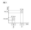
- FIG. 1 shows these current windows Strom_Tag and Strom_Nacht in a brightness / current diagram.
- operating points AP_Night or AP_Tag must be set, which lie within certain current ranges I_N_u and I_N_o or I_T_u and I_T_o.
- the problem is the maintenance of the operating points AP_Nacht and AP_Tag in case of component discontinuations with respect to the control and monitoring circuit or in the replacement of lighting elements, in particular LED's, by more modern with better light output.
- a development of the electronics is usually required.
- the work points AP_Night and AP_Tag must be reset. Improved light output leads to a reduction of the current is possible.
- a current reduction to adapt the operating point for the night mode AP_Night leads with high probability that the operating point for the day mode AP_Tag is above the setpoint.
- the adaptation effort for the development of the control and monitoring circuit as well as the required proof of safety can cause considerable costs.
- the trend shows that the luminous efficacy of the LEDs is continuous increases.
- the required current to be transmitted is always lower.
- the power windows must be monitored more accurately, which increases the susceptibility of the circuit and the availability of the light signal is adversely affected.
- the brightness of the LEDs decreases over time, so that there is a risk that the desired operating points in terms of brightness are left despite constant current window.
- the invention has for its object to provide a circuit of the generic type, which allows a constant maintenance of the signal brightness for the daytime and nighttime operation largely even with component cancellations and the replacement of lighting elements, in particular LEDs, in a simple manner.
- the object is achieved with the characterizing features of claim 1.
- controlling the brightness results in a high degree of independence from the performance of the signal generator and the light output of the light elements used.
- the safety certificate applies to a large power range of the signal transmitter.
- the time limit of the permitted duration of use of the lighting elements is eliminated, since age-related reduction in brightness is virtually compensated.
- a signal box In the signal box, the high signal voltage is converted to a low voltage for the signal generator by means of a signal transformer in order to minimize the power loss which arises in the signal cable due to the line resistance.
- the signal transformer has several taps. This allows the Voltage losses of the signal cable can be compensated by configuration. This distance-dependent adjustment is no longer required by the regulation of the brightness, so that a signal box in the present form is dispensable.
- the existing signal cables can be used regardless of their length.
- the reference variable for the brightness control is formed by brightness sensors which measure the actual brightness of the light elements. By means of the monitoring logic, a day or night setpoint value of the regulator current is generated for adjusting the setpoint brightness.
- the switching time between daytime and nighttime operation is specified by the control unit. This can be done for example by means of different waveform of the process voltage provided by the control part.
- a decentralized day-night switching can be provided according to claim 3.
- a sensor for measuring the ambient brightness of the light signal serves to specify the switching time.
- the brightness of the light signal optimally adapts to the location of the signal, eliminating the expense of providing additional nighttime voltage.
- the signal generator may be configured or configured to optimally control the intensity of the signal depending on the brightness of the signal environment.
- the controller is not safe in terms of signal design - in contrast to the monitoring logic and the brightness sensors for measuring the signal brightness and possibly the sensors for measuring the ambient brightness.
- the supervision the brightness is thus safety relevant, z. B. by a multiple execution of the monitoring logic and the connected brightness sensors.
- the monitoring logic and the associated brightness sensors can also be used in a simple design. The functionality is fully preserved. Even a graded security, the monitoring logic including sensors is only used twice, is conceivable.
- the controller is connected to an AC / DC converter, which converts the fluctuating process voltage into a lower constant DC voltage.
- the control principle is based on the fact that the adjustment of current and voltage for the lighting elements via this conversion takes place in such a way that the actual brightness corresponds to the setpoint brightness of the light signal.
- a pulse width modulation can be interposed.
- a signal transformer for converting the high signal voltage to a low voltage for the signal generator is dispensable by using the more compact and lighter AC / DC converter.
- a logic for the day-night switching which generates the desired value and a reference voltage for monitoring the operating point for the day or night operation, wherein the reference voltage and the brightness actual value of the light signal corresponding output signal the brightness sensors are compared by means of a comparator whose output signal is associated with a the energization state of the monitoring logic associated high or low level of a signal by means of an AND gate, wherein in the event that the signal brightness does not correspond to the predetermined operating point, a switch switches through and signaled the actuator the error state.
- the day / night switching is preferably designed for central day / night switching according to claim 2 and / or decentralized day / night switching according to claim 3.
- this information is provided according to claim 7 as an output for the connection of a train control device available.
- the monitoring logic LÜ generated with the voltage converter DCW from the voltage drop across a resistor RS a constant voltage U_Hi, for example 5 V. From this voltage U_Hi a signal E is generated, which after switching on the process voltage UP by the control part St in a delay time tv of Low L goes high.
- a logic for the day / night switching T / N logic generates a reference voltage Ref_T / N for a downstream comparator C, whose second input is acted upon by the actual brightness signal H actual of the brightness sensors SL.
- the output CA of Komparatos C is linked by means of an AND gate LA with the signal E such that in the event of an error, d. H.
- a switch S is turned on and the control part St via a resistor RF a high current and thus signaled an error condition.
- the actuator St can then initiate a corresponding failure processing.
- the logic for the day / night switching TN logic also forms the setpoint Hsetpoint for the brightness control HR.
- Two modes are possible, namely a decentralized day / night switchover or a central day / night switchover.
- sensors SH measure the brightness of the environment. From this the logic for day / night switching forms TN logic the setpoint Hsoll for the brightness control HR and the reference value Ref_T / N for the monitoring of the operating point AP_Night or AP_Tag.
- the signal brightness adapts optimally to the location of the signal.
- the information as to whether the signal generator Sign is to operate at the operating point AP_day or AP_night is transmitted from the actuating part St to the signal generator Sign.
- the control part St sends a gap-free alternating voltage UP when the operating point AP_Tag is to be set and an alternating voltage at which every n-th full wave is missing when the operating point AP_Nacht is to be set.
- the signal generator Sign can be controlled by the control element St, for example in the power range from 5 W to 50 W, without having to change the configuration data of the control element St.
- a process voltage UP of 200 V AC With a process voltage UP of 200 V AC, a current range of 25 mA to 250 mA results on the primary side. If the control REG is realized in such a way that a current> 40 mA always flows on the primary side, and if the resistance RF is dimensioned so that a current> 1 A flows in the event of a fault, an interference-insensitive signal connection can be realized due to the large current gaps.
- control element St measures a current ⁇ 40 mA
- the signal generator Sign is switched off, while with a current range from 40 mA to 250 mA there is a proper energization of the signal generator Sign and an error has occurred with a current> 1 A.
- line resistance RL 140 ohms, there is a power loss in the cable of 0.23 W at 40 mA and 8.75 W at 250 mA.
- An output Ein_OK of the signal generator Sign can be used for the connection of a train control device, since the monitoring logic LÜ is the information about the BestromungsTalk.
- the invention is not limited to the embodiment given above. Rather, a number of variants are conceivable, which make use of the features of the invention even with fundamentally different type.
Landscapes
- Engineering & Computer Science (AREA)
- Mechanical Engineering (AREA)
- Train Traffic Observation, Control, And Security (AREA)
- Circuit Arrangement For Electric Light Sources In General (AREA)
Abstract
Description
Die Erfindung betrifft eine Schaltung zur Ansteuerung und Überwachung eines Lichtsignals gemäß dem Oberbegriff des Anspruchs 1.The invention relates to a circuit for controlling and monitoring a light signal according to the preamble of
Lichtsignale, insbesondere im Straßen- und Schienenverkehr, müssen im Tagbetrieb eine größere Helligkeit als im Nachtbetrieb aufweisen. Bei Lichtsignalen in der Eisenbahntechnik wird die Helligkeit über Stromfenster, die vom Signalgeber vorgegeben werden, gesteuert. Figur 1 zeigt diese Stromfenster Strom_Tag und Strom_Nacht in einem Helligkeit/Strom-Diagramm. Um die gewünschte Helligkeit Hell_Nacht bzw. Hell_Tag zu erreichen, müssen Arbeitspunkte AP_Nacht bzw. AP_Tag eingestellt werden, die innerhalb bestimmter Strombereiche I_N_u und I_N_o bzw. I_T_u und I_T_o liegen. Problematisch ist die Beibehaltung der Arbeitspunkte AP_Nacht und AP_Tag bei Bauteileabkündigungen bezüglich der Ansteuer- und Überwachungsschaltung oder bei dem Ersatz von Leuchtelementen, insbesondere LED's, durch modernere mit besserer Lichtausbeute. In solchen Fällen ist in der Regel eine Umentwicklung der Elektronik erforderlich. Die Arbeitspunkte AP_Nacht und AP_Tag müssen neu eingestellt werden. Verbesserte Lichtausbeute führt dazu, dass eine Reduzierung des Stromes möglich wird. Eine Stromreduzierung zur Anpassung des Arbeitspunktes für den Nachtbetrieb AP_Nacht führt jedoch mit großer Wahrscheinlichkeit dazu, dass der Arbeitspunkt für den Tagbetrieb AP_Tag oberhalb des Sollwertes liegt. Der Anpassungsaufwand für die Umentwicklung der Ansteuer- und Überwachungsschaltung sowie die erforderliche Sicherheitsnachweisführung können erhebliche Kosten verursachen. Der Trend zeigt, dass die Lichtausbeute der Leuchtdioden kontinuierlich steigt. Dadurch wird der zu übertragende erforderliche Strom immer geringer. Die Stromfenster müssen immer genauer überwacht werden, wodurch sich die Störanfälligkeit der Schaltung erhöht und die Verfügbarkeit des Lichtsignals negativ beeinflusst wird. Außerdem ist zu berücksichtigen, dass die Helligkeit der Leuchtdioden im Laufe der Zeit abnimmt, so dass die Gefahr besteht, dass die gewünschten Arbeitspunkte bezüglich der Helligkeit trotz konstanter Stromfenster verlassen werden.Light signals, especially in road and rail traffic, must have a greater brightness in daytime operation than in nighttime operation. In the case of light signals in railway engineering, the brightness is controlled via current windows, which are specified by the signal generator. FIG. 1 shows these current windows Strom_Tag and Strom_Nacht in a brightness / current diagram. In order to achieve the desired Bright_Night or Hell_Tag brightness, operating points AP_Night or AP_Tag must be set, which lie within certain current ranges I_N_u and I_N_o or I_T_u and I_T_o. The problem is the maintenance of the operating points AP_Nacht and AP_Tag in case of component discontinuations with respect to the control and monitoring circuit or in the replacement of lighting elements, in particular LED's, by more modern with better light output. In such cases, a development of the electronics is usually required. The work points AP_Night and AP_Tag must be reset. Improved light output leads to a reduction of the current is possible. However, a current reduction to adapt the operating point for the night mode AP_Night leads with high probability that the operating point for the day mode AP_Tag is above the setpoint. The adaptation effort for the development of the control and monitoring circuit as well as the required proof of safety can cause considerable costs. The trend shows that the luminous efficacy of the LEDs is continuous increases. As a result, the required current to be transmitted is always lower. The power windows must be monitored more accurately, which increases the susceptibility of the circuit and the availability of the light signal is adversely affected. In addition, it should be noted that the brightness of the LEDs decreases over time, so that there is a risk that the desired operating points in terms of brightness are left despite constant current window.
Der Erfindung liegt die Aufgabe zugrunde, eine Schaltung der gattungsgemäßen Art anzugeben, die eine Konstanthaltung der Signalhelligkeit für den Tag- und den Nachtbetrieb weitgehend auch bei Bauteileabkündigungen und den Austausch von Leuchtelementen, insbesondere LED's, auf einfache Weise ermöglicht.The invention has for its object to provide a circuit of the generic type, which allows a constant maintenance of the signal brightness for the daytime and nighttime operation largely even with component cancellations and the replacement of lighting elements, in particular LEDs, in a simple manner.
Erfindungsgemäß wird die Aufgabe mit den kennzeichnenden Merkmalen des Anspruchs 1 gelöst. Durch die Regelung der Helligkeit ergibt sich eine weitgehende Unabhängigkeit von der Leistung des Signalgebers und von der Lichtleistung der verwendeten Leuchtelemente. Infolgedessen ist eine Konfigurierung bzw. Projektierung des Stellteils für die Anpassung an die Leistung des Signalgebers nicht mehr erforderlich. Der Sicherheitsnachweis gilt für einen großen Leistungsbereich des Signalgebers. Außerdem entfällt die zeitliche Begrenzung der erlaubten Einsatzdauer der Leuchtelemente, da altersbedingte Helligkeitsabnahme quasi ausgeregelt wird.According to the invention the object is achieved with the characterizing features of
Für die Signalansteuerung ist üblicherweise ein Signalkasten erforderlich. Im Signalkasten erfolgt die Umsetzung der hohen Signalspannung auf eine Niederspannung für den Signalgeber mittels Signaltrafos, um die Verlustleistung, die im Signalkabel durch den Leitungswiderstand entsteht, zu minimieren. Der Signaltrafo hat mehrere Anzapfungen. Dadurch können die Spannungsverluste des Signalkabels durch Konfigurierung kompensiert werden. Diese entfernungsabhängige Einstellung ist durch die Regelung der Helligkeit nicht mehr erforderlich, so dass ein Signalkasten in der heutigen Form entbehrlich ist. Die vorhandenen Signalkabel können unabhängig von deren Länge weiter verwendet werden.For the signal control usually a signal box is required. In the signal box, the high signal voltage is converted to a low voltage for the signal generator by means of a signal transformer in order to minimize the power loss which arises in the signal cable due to the line resistance. The signal transformer has several taps. This allows the Voltage losses of the signal cable can be compensated by configuration. This distance-dependent adjustment is no longer required by the regulation of the brightness, so that a signal box in the present form is dispensable. The existing signal cables can be used regardless of their length.
Die Führungsgröße für die Helligkeitsregelung wird über Helligkeitssensoren, die die Ist-Helligkeit der Leuchtelemente messen, gebildet. Mittels der Überwachungslogik wird zur Einregelung der Soll-Helligkeit ein Tag- bzw. Nacht-Sollwert des Reglerstromes erzeugt.The reference variable for the brightness control is formed by brightness sensors which measure the actual brightness of the light elements. By means of the monitoring logic, a day or night setpoint value of the regulator current is generated for adjusting the setpoint brightness.
Gemäß Anspruch 2 wird der Umschaltzeitpunkt zwischen Tag- und Nachtbetrieb durch das Stellteil vorgegeben. Das kann beispielsweise mittels unterschiedlicher Wellenform der durch das Stellteil bereitgestellten Prozessspannung erfolgen.According to claim 2, the switching time between daytime and nighttime operation is specified by the control unit. This can be done for example by means of different waveform of the process voltage provided by the control part.
Alternativ kann gemäß Anspruch 3 eine dezentrale Tag-Nacht-Umschaltung vorgesehen sein. Ein Sensor zur Messung der Umgebungshelligkeit des Lichtsignals dient dabei zur Vorgabe des Umschaltzeitpunktes. Die Helligkeit des Lichtsignals passt sich optimal an den Standort des Signals an, wobei der Aufwand für die zusätzliche Bereitstellung einer Nachtspannung entfällt. Der Signalgeber kann derart konfiguriert oder ausgeführt werden, dass er in Abhängigkeit von der Helligkeit der Signalumgebung die Lichtstärke des Signals optimal regelt.Alternatively, a decentralized day-night switching can be provided according to
Bei einer in Anspruch 4 gekennzeichneten vorteilhaften Ausführungsform ist der Regler nicht signaltechnisch sicher ausgebildet - im Gegensatz zu der Überwachungslogik und den Helligkeitssensoren zur Messung der Signalhelligkeit und ggf. den Sensoren zur Messung der Umgebungshelligkeit. Die Überwachung der Helligkeit erfolgt somit sicherheitsrelevant, z. B. durch eine Mehrfachausführung der Überwachungslogik sowie der angeschlossenen Helligkeitssensoren. Für nicht sicherheitsrelevante Signalanschaltungen können aber auch die Überwachungslogik und die zugehörigen Helligkeitssensoren in einfacher Ausführung eingesetzt werden. Die Funktionalität bleibt voll erhalten. Auch eine abgestufte Sicherheit, wobei die Überwachungslogik samt Sensoren nur zweifach eingesetzt wird, ist denkbar.In an advantageous embodiment characterized in claim 4, the controller is not safe in terms of signal design - in contrast to the monitoring logic and the brightness sensors for measuring the signal brightness and possibly the sensors for measuring the ambient brightness. The supervision the brightness is thus safety relevant, z. B. by a multiple execution of the monitoring logic and the connected brightness sensors. For non-safety-relevant signal connections, however, the monitoring logic and the associated brightness sensors can also be used in a simple design. The functionality is fully preserved. Even a graded security, the monitoring logic including sensors is only used twice, is conceivable.
Gemäß Anspruch 5 ist der Regler mit einem AC/DC-Wandler beschaltet, der die schwankende Prozessspannung in eine niedrigere konstante Gleichspannung umwandelt. Das Regelprinzip basiert dabei darauf, dass die Einstellung von Strom und Spannung für die Leuchtelemente über diese Wandlung derart erfolgt, dass die Ist-Helligkeit der Soll-Helligkeit des Lichtsignals entspricht. Gegebenenfalls kann zusätzlich eine Pulsweitenmodulation zwischengeschaltet werden. Ein Signaltrafo zur Umsetzung der hohen Signalspannung auf eine Niederspannung für den Signalgeber ist durch die Verwendung des kompakteren und leichteren AC/DC-Wandlers entbehrlich.According to claim 5, the controller is connected to an AC / DC converter, which converts the fluctuating process voltage into a lower constant DC voltage. The control principle is based on the fact that the adjustment of current and voltage for the lighting elements via this conversion takes place in such a way that the actual brightness corresponds to the setpoint brightness of the light signal. Optionally, in addition a pulse width modulation can be interposed. A signal transformer for converting the high signal voltage to a low voltage for the signal generator is dispensable by using the more compact and lighter AC / DC converter.
Gemäß Anspruch 6 ist eine Logik für die Tag-Nacht-Umschaltung vorgesehen, die den Sollwert und eine Referenzspannung für die Überwachung des Arbeitspunktes für den Tag- bzw. Nachtbetrieb erzeugt, wobei die Referenzspannung und das dem Helligkeits-Ist-Wert des Lichtsignals entsprechende Ausgangssignal der Helligkeitssensoren mittels eines Komparators verglichen werden, dessen Ausgangssignal mit einem dem Bestromungszustand der Überwachungslogik zugeordneten High- bzw. Low-Level eines Signals mittels eines UND-Gatters verknüpft wird, wobei für den Fall, dass die Signalhelligkeit nicht dem vorgegebenen Arbeitspunkt entspricht, ein Schalter durchschaltet und dem Stellteil den Fehlerzustand signalisiert. Die Tag/Nacht-Umschaltung ist bevorzugt für zentrale Tag/Nacht-Umschaltung gemäß Anspruch 2 und/oder dezentrale Tag/Nacht-Umschaltung gemäß Anspruch 3 ausgebildet.According to claim 6, a logic for the day-night switching is provided, which generates the desired value and a reference voltage for monitoring the operating point for the day or night operation, wherein the reference voltage and the brightness actual value of the light signal corresponding output signal the brightness sensors are compared by means of a comparator whose output signal is associated with a the energization state of the monitoring logic associated high or low level of a signal by means of an AND gate, wherein in the event that the signal brightness does not correspond to the predetermined operating point, a switch switches through and signaled the actuator the error state. The day / night switching is preferably designed for central day / night switching according to claim 2 and / or decentralized day / night switching according to
Da in der Überwachungslogik die Information vorliegt, ob ein Signalgeber ordnungsgemäß eingeschaltet ist, wird diese Information gemäß Anspruch 7 als Ausgang für den Anschluss einer Zugbeeinflussungseinrichtung zur Verfügung gestellt.Since the information is present in the monitoring logic, whether a signal generator is switched on properly, this information is provided according to claim 7 as an output for the connection of a train control device available.
Die Erfindung wird nachfolgend anhand figürlicher Darstellungen näher erläutert.The invention will be explained in more detail with reference to figurative representations.
Es zeigen:
Figur 1- ein Helligkeits-Strom-Diagramm und
- Figur 2
- das Grundprinzip einer Schaltung zur Ansteuerung und Überwachung eines Lichtsignals.
- FIG. 1
- a brightness-current diagram and
- FIG. 2
- the basic principle of a circuit for controlling and monitoring a light signal.
Das oben erläuterte Diagramm veranschaulicht die Lage der Arbeitspunkte AP_Nacht und AP_Tag, die mit der Schaltung nach Figur 2 eingestellt und überwacht werden. Die Schaltung besteht im Wesentlichen aus einem Stellteil St und einem Signalgeber Sign, wobei der Signalgeber Sign sowohl die Optik als auch die Elektronik im Signal umfassen soll. Als Leuchtelemente sind Leuchtdioden LED vorgesehen. Die LED's sind in einen Regelkreis REG zur Regelung ihrer Helligkeit eingebunden. Diese Regelung wird nicht signaltechnisch sicher ausgeführt, wogegen die Überwachung der Helligkeit signaltechnisch sicher durch eine mehrfache Überwachungslogik LÜ mit angeschlossenen ebenfalls mehrfachen Helligkeitssensoren SL, die die Ist-Helligkeit Hist der LED's messen, erfolgt. Die Einstellung von Strom und Spannung für die LED's kann durch folgende Regelungen erfolgen:
- Ein AC/DC-Wandler AC_DC wandelt eine hohe schwankende Prozessspannung UP, die von dem Stellteil St geliefert wird, in eine niedrige konstante Gleichspannung, wobei die Helligkeit zum Beispiel auf Basis einer Pulsweitenmodulation verlustarm geregelt wird.
- Der AC/DC-Wandler AC_DC wandelt die hohe schwankend Prozessspannung UP in eine niedrige Gleichspannung derart um, dass die Sollhelligkeit Hsoll dem Ist-Wert Hist entspricht.
- An AC / DC converter AC_DC converts a high fluctuating process voltage UP, which is supplied by the actuator St is, in a low constant DC voltage, the brightness is controlled loss, for example, based on a pulse width modulation.
- The AC / DC converter AC_DC converts the high fluctuating process voltage UP into a low DC voltage such that the setpoint brightness Hsoll corresponds to the actual value Hist.
Die Überwachungslogik LÜ erzeugt mit dem Spannungswandler DCW aus dem Spannungsabfall an einem Widerstand RS eine konstante Spannung U_Hi, beispielsweise 5 V. Aus dieser Spannung U_Hi wird ein Signal E erzeugt, das nach dem Einschalten der Prozessspannung UP durch das Stellteil St in einer Verzögerungszeit tv von Low L auf High H geht. Eine Logik für die Tag/Nacht-Umschaltung T/N-Logik erzeugt eine Referenzspannung Ref_T/N für einen nachgeschalteten Komparator C, dessen zweiter Eingang von dem Ist-Helligkeitssignal Hist der Helligkeitssensoren SL beaufschlagt ist. Das Ausgangssignal CA des Komparatos C wird mittels eines UND-Gatters LA mit dem Signal E derart verknüpft, dass im Fehlerfall, d. h. die Helligkeit ist nicht im Arbeitspunkt AP_Nacht bzw. AP_Tag, ein Schalter S durchschaltet und dem Stellteil St über einen Widerstand RF einen hohen Strom und damit einen Fehlerzustand signalisiert. Das Stellteil St kann daraufhin eine entsprechende Ausfallbearbeitung einleiten.The monitoring logic LÜ generated with the voltage converter DCW from the voltage drop across a resistor RS a constant voltage U_Hi, for example 5 V. From this voltage U_Hi a signal E is generated, which after switching on the process voltage UP by the control part St in a delay time tv of Low L goes high. A logic for the day / night switching T / N logic generates a reference voltage Ref_T / N for a downstream comparator C, whose second input is acted upon by the actual brightness signal H actual of the brightness sensors SL. The output CA of Komparatos C is linked by means of an AND gate LA with the signal E such that in the event of an error, d. H. the brightness is not in the operating point AP_Nacht or AP_Tag, a switch S is turned on and the control part St via a resistor RF a high current and thus signaled an error condition. The actuator St can then initiate a corresponding failure processing.
Die Logik für die Tag/Nacht-Umschaltung TN-Logik bildet neben dem Referenzwert Ref_T/N für die Überwachung des Arbeitspunktes AP_Nacht bzw. AP_Tag auch den Sollwert Hsoll für die Helligkeitsregelung HR. Dabei sind zwei Betriebsarten möglich, nämlich eine dezentrale Tag/Nacht-Umschaltung oder eine zentrale Tag/Nacht-Umschaltung. Bei der dezentralen Tag/Nacht - Umschaltung messen Sensoren SH die Helligkeit der Umgebung. Daraus bildet die Logik für die Tag/Nacht-Umschaltung TN-Logik den Sollwert Hsoll für die Helligkeitsregelung HR und den Referenzwert Ref_T/N für die Überwachung des Arbeitspunktes AP_Nacht bzw. AP_Tag. Die Signalhelligkeit passt sich optimal an den Standort des Signals an. Bei der zentralen Tag/Nacht-Umschaltung wird die Information, ob der Signalgeber Sign im Arbeitspunkt AP_Tag oder AP_Nacht arbeiten soll, vom Stellteil St an den Signalgeber Sign übermittelt. Dazu sendet das Stellteil St eine lückenlose Wechselspannung UP, wenn der Arbeitspunkt AP_Tag einzustellen ist und eine Wechselspannung, bei der jede n-te Vollwelle fehlt, wenn der Arbeitspunkt AP_Nacht einzustellen ist.In addition to the reference value Ref_T / N for monitoring the operating point AP_night or AP_day, the logic for the day / night switching TN logic also forms the setpoint Hsetpoint for the brightness control HR. Two modes are possible, namely a decentralized day / night switchover or a central day / night switchover. In decentralized day / night switching, sensors SH measure the brightness of the environment. From this the logic for day / night switching forms TN logic the setpoint Hsoll for the brightness control HR and the reference value Ref_T / N for the monitoring of the operating point AP_Night or AP_Tag. The signal brightness adapts optimally to the location of the signal. In the case of the central day / night switching, the information as to whether the signal generator Sign is to operate at the operating point AP_day or AP_night is transmitted from the actuating part St to the signal generator Sign. For this purpose, the control part St sends a gap-free alternating voltage UP when the operating point AP_Tag is to be set and an alternating voltage at which every n-th full wave is missing when the operating point AP_Nacht is to be set.
Der Signalgeber Sign kann vom Stellteil St beispielsweise im Leistungsbereich von 5 W bis 50 W angesteuert werden, ohne dass Projektierungsdaten des Stellteils St geändert werden müssen. Bei einer Prozessspannung UP von 200 V AC ergibt sich auf der Primärseite ein Strombereich von 25 mA bis 250 mA. Wird die Regelung REG so realisiert, dass primärseitig immer ein Strom > 40 mA fließt und wird der Widerstand RF so bemessen, dass im Fehlerfall ein Strom > 1 A fließt, so lässt sich aufgrund der großen Stromabstände eine störunempfindliche Signalanschaltung realisieren. Misst das Stellteil St einen Strom < 40 mA, so ist der Signalgeber Sign ausgeschaltet, während bei einem Strombereich von 40 mA bis 250 mA eine ordnungsgemäße Bestromung des Signalgebers Sign vorliegt und bei einem Strom > 1 A ein Fehler aufgetreten ist. Bei einem Leitungswiderstand RL von 140 Ohm ergibt sich eine Verlustleistung im Kabel von 0,23 W bei 40 mA und 8,75 W bei 250 mA.The signal generator Sign can be controlled by the control element St, for example in the power range from 5 W to 50 W, without having to change the configuration data of the control element St. With a process voltage UP of 200 V AC, a current range of 25 mA to 250 mA results on the primary side. If the control REG is realized in such a way that a current> 40 mA always flows on the primary side, and if the resistance RF is dimensioned so that a current> 1 A flows in the event of a fault, an interference-insensitive signal connection can be realized due to the large current gaps. If the control element St measures a current <40 mA, then the signal generator Sign is switched off, while with a current range from 40 mA to 250 mA there is a proper energization of the signal generator Sign and an error has occurred with a current> 1 A. With a line resistance RL of 140 ohms, there is a power loss in the cable of 0.23 W at 40 mA and 8.75 W at 250 mA.
Ein Ausgang Ein_OK des Signalgebers Sign kann für den Anschluss einer Zugbeeinflussungseinrichtung genutzt werden, da der Überwachungslogik LÜ die Information über den Bestromungszustand vorliegt.An output Ein_OK of the signal generator Sign can be used for the connection of a train control device, since the monitoring logic LÜ is the information about the Bestromungszustand.
Die Erfindung beschränkt sich nicht auf das vorstehend angegebene Ausführungsbeispiel. Vielmehr ist eine Anzahl von Varianten denkbar, welche auch bei grundsätzlich andersartiger Ausführung von den Merkmalen der Erfindung Gebrauch machen.The invention is not limited to the embodiment given above. Rather, a number of variants are conceivable, which make use of the features of the invention even with fundamentally different type.
Claims (7)
dadurch gekennzeichnet , dass
der Signalgeber (Sign) einen Regler (REG) aufweist, der über Helligkeitssensoren (SL) zur Messung der Helligkeit des Lichtsignals mit einer Überwachungslogik (LÜ) verbunden ist, die einen Tag- bzw. Nacht-Sollwert des Stromfensters (Strom_Tag, Strom_Nacht) für den Regler (REG) erzeugt.Circuit for controlling and monitoring a light signal, in particular an LED signal, with an actuating part (St) for providing a process voltage (UP) and a signal generator (Sign) for specifying current windows (Strom_Tag, Strom_Nacht) for daytime operation and nighttime operation,
characterized in that
the signal generator (Sign) has a regulator (REG), which is connected via brightness sensors (SL) for measuring the brightness of the light signal with a monitoring logic (LÜ), a day or night setpoint of the current window (Strom_Tag, Strom_Nacht) for generates the regulator (REG).
dadurch gekennzeichnet , dass
das Stellteil (St) Mittel zur Vorgabe des Umschaltzeitpunktes zwischen Tag- und Nachtbetrieb aufweist.Circuit according to claim 1,
characterized in that
the control part (St) has means for specifying the changeover time between daytime and nighttime operation.
dadurch gekennzeichnet , dass
mindestens ein Sensor (SH) zur Messung der Umgebungshelligkeit des Lichtsignals zur Vorgabe des Umschaltzeitpunktes zwischen Tag- und Nachtbetrieb vorgesehen ist.Circuit according to claim 1,
characterized in that
at least one sensor (SH) is provided for measuring the ambient brightness of the light signal for specifying the switching time between daytime and nighttime operation.
dadurch gekennzeichnet , dass
der Regler (REG) nicht signaltechnisch sicher und die Überwachungslogik (LÜ) sowie die Helligkeitssensoren (SL) zur Messung der Signalhelligkeit und ggf. die Sensoren (SH) zur Messung der Umgebungshelligkeit signaltechnisch sicher ausgebildet sind.Circuit according to any preceding claim,
characterized in that
the controller (REG) is not safe in terms of signaling and the monitoring logic (LÜ) and the brightness sensors (SL) for measuring the signal brightness and possibly the sensors (SH) for measuring the ambient brightness are signal-technically safe.
dadurch gekennzeichnet , dass
der Regler (REG) einen AC/DC-Wandler (AC_DC) zur Wandlung der schwankenden Prozessspannung (UP) in eine niedrigere Gleichspannung derart aufweist, dass die Ist-Helligkeit (Hist), ggf. unter Zwischenschaltung einer Pulsweitenmodulation, der Soll-Helligkeit (Hsoll) des Lichtsignals entspricht.Circuit according to one of the preceding claims,
characterized in that
the regulator (REG) has an AC / DC converter (AC_DC) for converting the fluctuating process voltage (UP) into a lower DC voltage such that the actual brightness (Hist), possibly with the interposition of a pulse width modulation, the target brightness ( Hsoll) corresponds to the light signal.
dadurch gekennzeichnet , dass
die Überwachungslogik (LÜ) eine Logik für die Tag/Nacht-Umschaltung (T/N-Logik) aufweist, die den Sollwert und eine Referenzspannung (Ref_T/N) für die Überwachung des Stromfensters (Strom_Tag, Strom_Nacht) für den Tag- bzw. Nachtbetrieb erzeugt, wobei die Referenzspannung (Ref_T/N) und das dem Helligkeits-Ist-Wert (Hist) des Lichtsignals entsprechende Ausgangssignal der Helligkeitssensoren (SL) mittels eines Komparators (C) vergleichen werden, dessen Ausgangssignal (CA) mit einem dem Bestromungszustand der Überwachungslogik (LÜ) zugeordneten High (H)- bzw. Low (L)- Level eines Signals (E) mittels eines UND-Gatters (LA) verknüpft wird, wobei für den Fall, dass die Signalhelligkeit nicht dem vorgegebenen Stromfenster (Strom_Tag, Strom_Nacht) entspricht, ein Schalter (S) durchschaltet und dem Stellteil (St) einen Fehlerzustand signalisiert.Circuit according to one of the preceding claims,
characterized in that
the monitoring logic (LÜ) has a logic for day / night switching (T / N logic), the setpoint and a reference voltage (Ref_T / N) for monitoring the current window (Strom_Tag, Strom_Nacht) for the day or Night mode generated, wherein the reference voltage (Ref_T / N) and the brightness actual value (Hist) of the light signal corresponding output of the brightness sensors (SL) by means of a comparator (C) are compared, the output signal (CA) with a the energization of the Monitoring logic (LÜ) associated high (H) or low (L) - level of a signal (E) by means of an AND gate (LA), wherein in the event that the signal brightness is not the predetermined current window (Strom_Tag, Strom_Nacht ), a switch (S) turns on and the control part (St) signals a fault condition.
dadurch gekennzeichnet , dass
die Überwachungslogik (LÜ) ein dem Bestromungszustand des Signalgebers (Sign) entsprechendes Signal (Ein_OK) erzeugt, das eine Zugbeeinflussungseinrichtung beaufschlagt.Circuit according to one of the preceding claims,
characterized in that
the monitoring logic (LÜ) generates a signal (Ein_OK) corresponding to the current status of the signal generator (Sign) which acts on a train-influencing device.
Applications Claiming Priority (1)
| Application Number | Priority Date | Filing Date | Title |
|---|---|---|---|
| DE102005023295A DE102005023295A1 (en) | 2005-05-12 | 2005-05-12 | Circuit for controlling and monitoring a light signal |
Publications (2)
| Publication Number | Publication Date |
|---|---|
| EP1722608A2 true EP1722608A2 (en) | 2006-11-15 |
| EP1722608A3 EP1722608A3 (en) | 2008-07-09 |
Family
ID=36827276
Family Applications (1)
| Application Number | Title | Priority Date | Filing Date |
|---|---|---|---|
| EP06112891A Withdrawn EP1722608A3 (en) | 2005-05-12 | 2006-04-21 | Circuit for operating and monitoring a light signalling device |
Country Status (3)
| Country | Link |
|---|---|
| US (1) | US20060256552A1 (en) |
| EP (1) | EP1722608A3 (en) |
| DE (1) | DE102005023295A1 (en) |
Cited By (10)
| Publication number | Priority date | Publication date | Assignee | Title |
|---|---|---|---|---|
| WO2011086027A1 (en) * | 2010-01-15 | 2011-07-21 | Siemens Aktiengesellschaft | Light signal |
| WO2011113794A1 (en) * | 2010-03-19 | 2011-09-22 | Siemens Aktiengesellschaft | Led light signal |
| WO2011146508A1 (en) * | 2010-05-18 | 2011-11-24 | General Electric Company | Signal detection system and method |
| EP2463174A1 (en) * | 2010-12-09 | 2012-06-13 | Siemens Schweiz AG | Method and device for replacing a bulb of a light signal |
| WO2013013944A3 (en) * | 2011-07-28 | 2013-03-28 | Siemens Aktiengesellschaft | Light signal |
| DE102013207416A1 (en) | 2013-04-24 | 2014-10-30 | Siemens Aktiengesellschaft | light signal |
| WO2015039879A1 (en) * | 2013-09-20 | 2015-03-26 | Siemens Aktiengesellschaft | Method for setting an led signal transmitter in terms of day and night mode, and led signal transmitter |
| EP2131628A3 (en) * | 2008-06-05 | 2015-05-20 | Siemens Aktiengesellschaft | Signal issuer |
| US9598093B2 (en) | 2010-05-18 | 2017-03-21 | Alstom Transport Technologies | Signal detection system and method |
| EP2488401B2 (en) † | 2009-10-16 | 2017-07-12 | Solari Di Udine Spa | Led-type luminous signaling device and relative control method |
Families Citing this family (3)
| Publication number | Priority date | Publication date | Assignee | Title |
|---|---|---|---|---|
| DE102007047847B4 (en) * | 2007-11-22 | 2018-02-22 | Swarco Traffic Systems Gmbh | Traffic signal system with signal transmitters and a control device for controlling lights in the signalers |
| DE102011017681A1 (en) | 2011-04-28 | 2012-10-31 | Siemens Aktiengesellschaft | Light signal device and method for controlling a light signal device |
| DE102013108689B3 (en) * | 2013-08-11 | 2014-11-13 | Pintsch Bamag Antriebs- Und Verkehrstechnik Gmbh | Circuit for controlling the power consumption of an LED unit and LED light with such a LED unit |
Citations (7)
| Publication number | Priority date | Publication date | Assignee | Title |
|---|---|---|---|---|
| EP0678078A1 (en) * | 1993-11-05 | 1995-10-25 | Siemens Integra Verkehrstechnik Ag | Circuit for emitting optical signals |
| DE19608886A1 (en) * | 1996-03-07 | 1997-09-11 | Machate Juergen | Control and monitoring apparatus for traffic light sources |
| WO1998049872A1 (en) * | 1997-04-30 | 1998-11-05 | Signal House Limited | Traffic signals |
| US6236331B1 (en) * | 1998-02-20 | 2001-05-22 | Newled Technologies Inc. | LED traffic light intensity controller |
| DE10201908C1 (en) * | 2002-01-19 | 2003-07-17 | Stuehrenberg Gmbh | Lamp for emitting a signal has a circuit board with LEDs in parallel serial circuits each controlled by a transistor connected as a current supply. |
| DE10208462A1 (en) * | 2002-02-27 | 2003-09-04 | Osram Opto Semiconductors Gmbh | lighting arrangement |
| DE20220900U1 (en) * | 2002-11-07 | 2004-05-27 | Schmeling, Till, Dr.rer.nat. | LED-based navigation and position lights arrangement e.g. for ships and water craft and also for road signs, includes light and color sensors for automatically adjusting required color and light-intensity |
Family Cites Families (2)
| Publication number | Priority date | Publication date | Assignee | Title |
|---|---|---|---|---|
| US5789868A (en) * | 1996-08-13 | 1998-08-04 | The Lamson & Sessions Co. | Timed photocell switch circuit |
| DE10025821A1 (en) * | 2000-05-25 | 2002-07-25 | Sickinger Monika | LED light source |
-
2005
- 2005-05-12 DE DE102005023295A patent/DE102005023295A1/en not_active Withdrawn
-
2006
- 2006-04-21 EP EP06112891A patent/EP1722608A3/en not_active Withdrawn
- 2006-05-12 US US11/433,146 patent/US20060256552A1/en not_active Abandoned
Patent Citations (7)
| Publication number | Priority date | Publication date | Assignee | Title |
|---|---|---|---|---|
| EP0678078A1 (en) * | 1993-11-05 | 1995-10-25 | Siemens Integra Verkehrstechnik Ag | Circuit for emitting optical signals |
| DE19608886A1 (en) * | 1996-03-07 | 1997-09-11 | Machate Juergen | Control and monitoring apparatus for traffic light sources |
| WO1998049872A1 (en) * | 1997-04-30 | 1998-11-05 | Signal House Limited | Traffic signals |
| US6236331B1 (en) * | 1998-02-20 | 2001-05-22 | Newled Technologies Inc. | LED traffic light intensity controller |
| DE10201908C1 (en) * | 2002-01-19 | 2003-07-17 | Stuehrenberg Gmbh | Lamp for emitting a signal has a circuit board with LEDs in parallel serial circuits each controlled by a transistor connected as a current supply. |
| DE10208462A1 (en) * | 2002-02-27 | 2003-09-04 | Osram Opto Semiconductors Gmbh | lighting arrangement |
| DE20220900U1 (en) * | 2002-11-07 | 2004-05-27 | Schmeling, Till, Dr.rer.nat. | LED-based navigation and position lights arrangement e.g. for ships and water craft and also for road signs, includes light and color sensors for automatically adjusting required color and light-intensity |
Cited By (15)
| Publication number | Priority date | Publication date | Assignee | Title |
|---|---|---|---|---|
| EP2131628A3 (en) * | 2008-06-05 | 2015-05-20 | Siemens Aktiengesellschaft | Signal issuer |
| EP2488401B2 (en) † | 2009-10-16 | 2017-07-12 | Solari Di Udine Spa | Led-type luminous signaling device and relative control method |
| WO2011086027A1 (en) * | 2010-01-15 | 2011-07-21 | Siemens Aktiengesellschaft | Light signal |
| WO2011113794A1 (en) * | 2010-03-19 | 2011-09-22 | Siemens Aktiengesellschaft | Led light signal |
| WO2011146508A1 (en) * | 2010-05-18 | 2011-11-24 | General Electric Company | Signal detection system and method |
| US9598093B2 (en) | 2010-05-18 | 2017-03-21 | Alstom Transport Technologies | Signal detection system and method |
| EP2463174A1 (en) * | 2010-12-09 | 2012-06-13 | Siemens Schweiz AG | Method and device for replacing a bulb of a light signal |
| WO2012076313A1 (en) * | 2010-12-09 | 2012-06-14 | Siemens Schweiz Ag | Device and method for providing a replacement for an incandescent bulb |
| WO2013013944A3 (en) * | 2011-07-28 | 2013-03-28 | Siemens Aktiengesellschaft | Light signal |
| WO2014173713A2 (en) | 2013-04-24 | 2014-10-30 | Siemens Aktiengesellschaft | Light signal |
| DE102013207416A1 (en) | 2013-04-24 | 2014-10-30 | Siemens Aktiengesellschaft | light signal |
| WO2015039879A1 (en) * | 2013-09-20 | 2015-03-26 | Siemens Aktiengesellschaft | Method for setting an led signal transmitter in terms of day and night mode, and led signal transmitter |
| CN105557070A (en) * | 2013-09-20 | 2016-05-04 | 西门子公司 | Method for setting an LED signal transmitter in terms of day and night mode, and LED signal transmitter |
| CN105557070B (en) * | 2013-09-20 | 2017-06-30 | 西门子公司 | For method and LED signal transmitter on setting LED signal transmitter with night operation in the daytime |
| RU2634643C2 (en) * | 2013-09-20 | 2017-11-07 | Сименс Акциенгезелльшафт | Led alarm adjustment method to work in day and night mode and led alarm |
Also Published As
| Publication number | Publication date |
|---|---|
| DE102005023295A1 (en) | 2006-11-16 |
| EP1722608A3 (en) | 2008-07-09 |
| US20060256552A1 (en) | 2006-11-16 |
Similar Documents
| Publication | Publication Date | Title |
|---|---|---|
| EP1722608A2 (en) | Circuit for operating and monitoring a light signalling device | |
| AT14505U1 (en) | Method and device for data transmission via a load line and lighting system | |
| DE3421519A1 (en) | DEVICE FOR REGULATING AN AC CIRCUIT | |
| EP2974548B1 (en) | Lamp device with two interfaces | |
| DE3527828C2 (en) | ||
| DE60219066T2 (en) | PROGRAMMABLE SYSTEM FOR VOLTAGE STABILIZATION AND CONTROL IN PARTICULAR FOR IMPROVED MANAGEMENT OF LIGHTING UNITS WITH FLUORESCENT LAMPS AND SIMILAR | |
| EP1473976B1 (en) | Interface for digital and power line control signals and method for dimensioning such an interface | |
| EP2458946B1 (en) | Communication system for controlling electrical loads | |
| EP2704332B1 (en) | Emergency/safety lighting unit and method for controlling the same | |
| DE10261454A1 (en) | Motor control with a secure hold | |
| EP2876509B1 (en) | Safety control | |
| DE102011077387A1 (en) | Circuit arrangement for switching current in dependence of predeterminable switching signal, has semiconductor circuit breaker for controlling current intensity and driver circuit for receiving switching signal | |
| EP2458945B1 (en) | Transmission system for transmitting data telegrams over a load line | |
| DE102016121255A1 (en) | Control module for an electromechanical switching unit, relay module and control device | |
| EP3376485B1 (en) | Signal encoder unit with integrated return path | |
| DE3029851C2 (en) | Circuit arrangement for the safe control of a power consumer in terms of signaling | |
| DE3140559A1 (en) | Circuit arrangement for technically reliable operation of signal lights | |
| DE10029106B4 (en) | Method for controlling and corresponding circuit arrangement | |
| EP3689112B1 (en) | Extended signalling capacity in a dali system | |
| DE102011017681A1 (en) | Light signal device and method for controlling a light signal device | |
| DE102020204513B4 (en) | Illumination method and device | |
| EP2116108B1 (en) | Electronic ballast for a lamp | |
| DE102009043553A1 (en) | Switching arrangement for phase exact switching of alternating voltage, has relay with switching contact lying in load current cycle, where load current cycle has pair of connections | |
| EP3119166B1 (en) | System and operating device for an actuator | |
| DE10007895A1 (en) | Adaptor for interfacing constant current regulator to bus system, for airport navigation lighting system - has microcontroller for producing current reference values of constant current regulator from signals delivered via bus system |
Legal Events
| Date | Code | Title | Description |
|---|---|---|---|
| PUAI | Public reference made under article 153(3) epc to a published international application that has entered the european phase |
Free format text: ORIGINAL CODE: 0009012 |
|
| AK | Designated contracting states |
Kind code of ref document: A2 Designated state(s): AT BE BG CH CY CZ DE DK EE ES FI FR GB GR HU IE IS IT LI LT LU LV MC NL PL PT RO SE SI SK TR |
|
| AX | Request for extension of the european patent |
Extension state: AL BA HR MK YU |
|
| PUAL | Search report despatched |
Free format text: ORIGINAL CODE: 0009013 |
|
| AK | Designated contracting states |
Kind code of ref document: A3 Designated state(s): AT BE BG CH CY CZ DE DK EE ES FI FR GB GR HU IE IS IT LI LT LU LV MC NL PL PT RO SE SI SK TR |
|
| AX | Request for extension of the european patent |
Extension state: AL BA HR MK YU |
|
| AKX | Designation fees paid | ||
| STAA | Information on the status of an ep patent application or granted ep patent |
Free format text: STATUS: THE APPLICATION IS DEEMED TO BE WITHDRAWN |
|
| 18D | Application deemed to be withdrawn |
Effective date: 20090110 |
|
| REG | Reference to a national code |
Ref country code: DE Ref legal event code: 8566 |