EP1720599B1 - Device with a slidable safety member for positioning a cannula in a vein - Google Patents
Device with a slidable safety member for positioning a cannula in a vein Download PDFInfo
- Publication number
- EP1720599B1 EP1720599B1 EP05733010.2A EP05733010A EP1720599B1 EP 1720599 B1 EP1720599 B1 EP 1720599B1 EP 05733010 A EP05733010 A EP 05733010A EP 1720599 B1 EP1720599 B1 EP 1720599B1
- Authority
- EP
- European Patent Office
- Prior art keywords
- cage
- needle
- wall
- chamber
- hub
- Prior art date
- Legal status (The legal status is an assumption and is not a legal conclusion. Google has not performed a legal analysis and makes no representation as to the accuracy of the status listed.)
- Active
Links
- 210000003462 vein Anatomy 0.000 title claims description 7
- 210000003323 beak Anatomy 0.000 description 4
- 230000000717 retained effect Effects 0.000 description 3
- 235000021183 entrée Nutrition 0.000 description 2
- 230000014759 maintenance of location Effects 0.000 description 2
- 101100536354 Drosophila melanogaster tant gene Proteins 0.000 description 1
- 210000000941 bile Anatomy 0.000 description 1
- 238000006073 displacement reaction Methods 0.000 description 1
- 230000000694 effects Effects 0.000 description 1
- 238000000034 method Methods 0.000 description 1
- 230000035515 penetration Effects 0.000 description 1
- 238000000926 separation method Methods 0.000 description 1
Images


Classifications
-
- A—HUMAN NECESSITIES
- A61—MEDICAL OR VETERINARY SCIENCE; HYGIENE
- A61M—DEVICES FOR INTRODUCING MEDIA INTO, OR ONTO, THE BODY; DEVICES FOR TRANSDUCING BODY MEDIA OR FOR TAKING MEDIA FROM THE BODY; DEVICES FOR PRODUCING OR ENDING SLEEP OR STUPOR
- A61M25/00—Catheters; Hollow probes
- A61M25/01—Introducing, guiding, advancing, emplacing or holding catheters
- A61M25/06—Body-piercing guide needles or the like
- A61M25/065—Guide needles
-
- A—HUMAN NECESSITIES
- A61—MEDICAL OR VETERINARY SCIENCE; HYGIENE
- A61M—DEVICES FOR INTRODUCING MEDIA INTO, OR ONTO, THE BODY; DEVICES FOR TRANSDUCING BODY MEDIA OR FOR TAKING MEDIA FROM THE BODY; DEVICES FOR PRODUCING OR ENDING SLEEP OR STUPOR
- A61M25/00—Catheters; Hollow probes
- A61M25/01—Introducing, guiding, advancing, emplacing or holding catheters
- A61M25/06—Body-piercing guide needles or the like
- A61M25/0606—"Over-the-needle" catheter assemblies, e.g. I.V. catheters
-
- A—HUMAN NECESSITIES
- A61—MEDICAL OR VETERINARY SCIENCE; HYGIENE
- A61M—DEVICES FOR INTRODUCING MEDIA INTO, OR ONTO, THE BODY; DEVICES FOR TRANSDUCING BODY MEDIA OR FOR TAKING MEDIA FROM THE BODY; DEVICES FOR PRODUCING OR ENDING SLEEP OR STUPOR
- A61M25/00—Catheters; Hollow probes
- A61M25/01—Introducing, guiding, advancing, emplacing or holding catheters
- A61M25/06—Body-piercing guide needles or the like
- A61M25/0612—Devices for protecting the needle; Devices to help insertion of the needle, e.g. wings or holders
-
- A—HUMAN NECESSITIES
- A61—MEDICAL OR VETERINARY SCIENCE; HYGIENE
- A61M—DEVICES FOR INTRODUCING MEDIA INTO, OR ONTO, THE BODY; DEVICES FOR TRANSDUCING BODY MEDIA OR FOR TAKING MEDIA FROM THE BODY; DEVICES FOR PRODUCING OR ENDING SLEEP OR STUPOR
- A61M39/00—Tubes, tube connectors, tube couplings, valves, access sites or the like, specially adapted for medical use
- A61M39/10—Tube connectors; Tube couplings
-
- A—HUMAN NECESSITIES
- A61—MEDICAL OR VETERINARY SCIENCE; HYGIENE
- A61M—DEVICES FOR INTRODUCING MEDIA INTO, OR ONTO, THE BODY; DEVICES FOR TRANSDUCING BODY MEDIA OR FOR TAKING MEDIA FROM THE BODY; DEVICES FOR PRODUCING OR ENDING SLEEP OR STUPOR
- A61M5/00—Devices for bringing media into the body in a subcutaneous, intra-vascular or intramuscular way; Accessories therefor, e.g. filling or cleaning devices, arm-rests
- A61M5/178—Syringes
- A61M5/31—Details
- A61M5/32—Needles; Details of needles pertaining to their connection with syringe or hub; Accessories for bringing the needle into, or holding the needle on, the body; Devices for protection of needles
-
- A—HUMAN NECESSITIES
- A61—MEDICAL OR VETERINARY SCIENCE; HYGIENE
- A61M—DEVICES FOR INTRODUCING MEDIA INTO, OR ONTO, THE BODY; DEVICES FOR TRANSDUCING BODY MEDIA OR FOR TAKING MEDIA FROM THE BODY; DEVICES FOR PRODUCING OR ENDING SLEEP OR STUPOR
- A61M39/00—Tubes, tube connectors, tube couplings, valves, access sites or the like, specially adapted for medical use
- A61M39/10—Tube connectors; Tube couplings
- A61M39/1011—Locking means for securing connection; Additional tamper safeties
Definitions
- the present invention relates to devices used for the placement in a vein of a cannula consisting of a short tubular catheter proximal base, by means of a puncture needle.
- the introduction procedure includes a puncture phase in which the needle is pushed into the base of the catheter and into the catheter so that its tip exits at the distal end of the catheter and in which the operator punctates with this tip. the vein into which he wants to introduce the catheter, an introductory phase in which the operator slides the catheter on the needle distally to penetrate the catheter into the vein, and a withdrawal phase in which the operator remove the needle from the vein, catheter and catheter hub.
- the tip of the needle is in the open air and the risk arises that the operator who holds the catheter and its base with one hand and who holds the needle of the other hand, poorly controls the needle and pricks with its tip.
- EP 0832 666 discloses a device which has an intermediate piece between the base of a cannula and the end of a tube which serves to trap the needle.
- the intermediate piece is designed at one end for mounting the piece on the cannula base and at its opposite end for mounting on the tube piece for trapping the needle.
- the intermediate piece is not intended to trap the needle but to provide a seal.
- the assembly of the base of the cannula on this piece is made by screwing or conical wedging, which does not prevent the piece is detached from this base by awkwardness before the needle is removed.
- this device has a temporary hooking means of the tube which surrounds the needle on the intermediate piece, this attachment does not concern the temporary fixing of the intermediate piece on the base of the cannula.
- the publication US 4,900,307 discloses a device which is only intended to withdraw the needle inside a tube at the end of which is fixed a nose. This nose after mounting the needle in the device is permanently attached to the end of the tube.
- the device includes a manually operable trigger for triggering the withdrawal of the needle.
- the cage with a movable member transversely, held by the needle in a position where it is retained by the base of the catheter, and adapted to come of itself in a position release when the puncture end of the needle is withdrawn into the cage.
- the present invention aims to provide a cage provided with a retaining device freed from the aforementioned drawbacks and in particular a retaining device which is both visible outside the cage and the base and maintained by the needle in the retaining position as long as the puncture end of the needle is not withdrawn into the cage.
- An object of the invention is therefore a device for the introduction into a vein of a cannula consisting of a short tubular catheter with a proximal base, this device comprising a needle which has a puncture end and a cage which extends the cannula base proximally, this cage determining a slotted through chamber by the needle from a proximal inlet to a distal outlet and provided with a trap for retaining in the chamber the puncture end of the needle when the needle is extracted from the base of the catheter, the cage and the base being provided with retaining means cooperating to ensure a temporary retention of the cage on the base before the puncture end of the needle is trapped in the chamber of the cage, said retaining means comprising an outer flange formed on the base and an external spout provided on the cage to be retained by this flange, characterized in that the spout is formed on a body mo bile which has a wall through which a hole for the passage of the needle so that the passage of the needle in the
- the retaining member is a molded body which has two walls (9; 10) arranged at right angles. One of the walls (9) ends with a spout (11) and the other wall (10), which is pierced with a hole (12) for the passage of the needle.
- the rear part (6) of the cage determines a chamber (13) for the passage of the needle through the cage and determines the inlet (14) of this chamber while the front part (7) of the cage determines a transverse wall (15) for closing the chamber, this wall being pierced with a hole (16) which constitutes the outlet of the chamber.
- the front piece (7) determines a nose (17) adapted to be received in the base of the catheter.
- the rear part (6) of the cage is shaped so that the base of the needle fits on the back piece for the puncture ( figures 2 and 3 ).
- the transverse wall (15) of the front piece has lateral pins (18) able to snap into holes (19) in the wall of the chamber of the rear piece for fixing the two pieces.
- This transverse wall also determines slides (20) for sliding the wall (10) of the retaining member.
- this transverse wall is provided with a pin (21) adapted to be received in an oblong slot (22) of the sliding wall (10) to limit the lifting of the movable member.
- the base (2) of the short catheter has near its inlet a flange (23) for example a continuous or discontinuous outer flange, to stop the beak (11) of the guillotine and this beak has a ramp (24) adapted to gradually slide on the collar when the cage is pulled in the proximal direction ( Figures 6 to 8 ), which causes the lifting of the guillotine until this lifting is stopped by the pin (21) as seen in particular on the figure 8 .
- the positions of the pin (21) and the light (22) are adjusted so that this stop is not obtained before the nose has passed above the collar ( figure 7 ).
- Means are provided to prevent the guillotine returning to the low position after reaching the raised position.
- these means consist of flexible and resilient tabs (8) formed on the sides of the sliding wall (10) of the movable member and which are constrained by flanges (25) of the transverse wall ( 15) of the front part (7) of the cage until these tabs have reached the top of the flanges during the lifting of the guillotine ( Figures 11 and 12 ) position for which the legs relax outwards and rest on the ledges.
- means are also provided, known per se to prevent the puncture end of the needle from coming out of the cage through the proximal inlet of the chamber.
- the present invention does not in itself relate to a particular choice of such a device and, for the example only, there is shown a device constituted by a fixed transverse wall (26) in which is pierced the proximal inlet (14). of the cage and by a local bulge (27) of the right section of the needle.
- This bulge has been shown in some figures and exaggerated: it goes without saying that this bulge is designed not to prevent slippage of the needle in the cannula.
Description
La présente invention concerne les dispositifs utilisés pour la mise en place dans une veine d'une canule constituée d'un cathéter tubulaire court à embase proximale, au moyen d'une aiguille de ponction.The present invention relates to devices used for the placement in a vein of a cannula consisting of a short tubular catheter proximal base, by means of a puncture needle.
La procédure d'introduction comprend une phase de ponction dans laquelle l'aiguille est poussée dans l'embase du cathéter et dans le cathéter en sorte que sa pointe sorte à l'extrémité distale du cathéter et dans laquelle l'opérateur ponctionne avec cette pointe la veine dans laquelle il veut introduire le cathéter, une phase d'introduction dans laquelle l'opérateur fait glisser le cathéter sur l'aiguille en direction distale pour faire pénétrer le cathéter dans la veine, et une phase de retrait dans laquelle l'opérateur retire l'aiguille de la veine, du cathéter et de l'embase du cathéter.The introduction procedure includes a puncture phase in which the needle is pushed into the base of the catheter and into the catheter so that its tip exits at the distal end of the catheter and in which the operator punctates with this tip. the vein into which he wants to introduce the catheter, an introductory phase in which the operator slides the catheter on the needle distally to penetrate the catheter into the vein, and a withdrawal phase in which the operator remove the needle from the vein, catheter and catheter hub.
A l'issue de la phase de retrait, la pointe de l'aiguille se trouve à l'air libre et le risque se présente que l'opérateur qui tient le cathéter et son embase d'une main et qui tient l'aiguille de l'autre main, contrôle mal l'aiguille et se pique avec sa pointe.At the end of the withdrawal phase, the tip of the needle is in the open air and the risk arises that the operator who holds the catheter and its base with one hand and who holds the needle of the other hand, poorly controls the needle and pricks with its tip.
La publication
La pièce intermédiaire est conçue à une extrémité pour le montage de la pièce sur l'embase de la canule et à son extrémité opposée pour le montage sur la pièce du tube destiné à piéger l'aiguille.The intermediate piece is designed at one end for mounting the piece on the cannula base and at its opposite end for mounting on the tube piece for trapping the needle.
La pièce intermédiaire n'est pas destinée à piéger l'aiguille mais à fournir un joint d'étanchéité.The intermediate piece is not intended to trap the needle but to provide a seal.
Le montage de l'embase de la canule sur cette pièce est réalisé par vissage ou par coincement conique, ce qui n'interdit pas que la pièce soit détachée de cette embase par maladresse avant que l'aiguille soit retirée.The assembly of the base of the cannula on this piece is made by screwing or conical wedging, which does not prevent the piece is detached from this base by awkwardness before the needle is removed.
Si ce dispositif présente un moyen d'accrochage provisoire du tube qui entoure l'aiguille sur la pièce intermédiaire, cet accrochage ne concerne pas la fixation provisoire de la pièce intermédiaire sur l'embase de la canule.If this device has a temporary hooking means of the tube which surrounds the needle on the intermediate piece, this attachment does not concern the temporary fixing of the intermediate piece on the base of the cannula.
La publication
Il est également connu de fixer provisoirement dans le prolongement vers l'arrière de l'embase du cathéter une cage détachable au travers de laquelle l'aiguille peut coulisser et qui est munie d'un piège pour retenir dans la chambre l'extrémité de ponction de l'aiguille lorsque celle-ci sort de l'embase et pour rester en place sur cette extrémité lorsque la cage est détachée de l'embase voir document
Pour fixer provisoirement la cage sur l'embase de l'aiguille, il est connu de réaliser un emboîtement conique à friction de la cage dans ou sur l'embase de l'aiguille, en sorte que la cage se détache de l'embase sous l'effet d'une traction exercée axialement sur l'aiguille après que l'extrémité de ponction de l'aiguille soit arrivée dans la cage (
Le risque subsiste toutefois que la cage se détache de l'embase prématurément avant que l'extrémité de ponction de l'aiguille soit piégée dans la cage.The risk remains however that the cage is detached from the base prematurely before the puncture end of the needle is trapped in the cage.
Pour éviter ce risque, il a été préconisé de munir la cage d'un organe mobile transversalement, maintenu par l'aiguille dans une position où il est retenu par l'embase du cathéter, et apte à venir de lui-même dans une position de libération lorsque l'extrémité de ponction de l'aiguille est retirée dans la cage.To avoid this risk, it has been recommended to provide the cage with a movable member transversely, held by the needle in a position where it is retained by the base of the catheter, and adapted to come of itself in a position release when the puncture end of the needle is withdrawn into the cage.
La publication
Ce dispositif de retenue, entièrement caché dans l'embase et dans la cage, est difficile à contrôler et le déplacement radial automatique de l'ergot peut être insuffisant pour libérer la cage de l'embase.This retainer, completely hidden in the base and in the cage, is difficult to control and the automatic radial displacement of the lug may be insufficient to release the cage of the base.
La publication
La présente invention a pour but de fournir une cage muni d'un dispositif de retenue affranchi des inconvénients précités et notamment un dispositif de retenu qui soit à la fois apparent à l'extérieur de la cage et de l'embase et maintenu par l'aiguille en position de retenue tant que l'extrémité de ponction de l'aiguille n'est pas retirée dans la cage.The present invention aims to provide a cage provided with a retaining device freed from the aforementioned drawbacks and in particular a retaining device which is both visible outside the cage and the base and maintained by the needle in the retaining position as long as the puncture end of the needle is not withdrawn into the cage.
Un objet de l'invention est donc un dispositif pour la mise en place dans une veine d'une canule constitué d'un cathéter tubulaire court à embase proximale, ce dispositif comprenant une aiguille qui présente une extrémité de ponction et une cage qui prolonge l'embase de la canule en direction proximale, cette cage déterminant une chambre traversée à coulisse par l'aiguille d'une entrée proximale à une sortie distale et munie d'un piège pour retenir dans la chambre l'extrémité de ponction de l'aiguille lorsque l'aiguille est extraite de l'embase du cathéter, la cage et l'embase étant munis de moyens de retenue coopérant pour assurer une retenue provisoire de la cage sur l'embase avant que l'extrémité de ponction de l'aiguille soit piégée dans la chambre de la cage, lesdits moyens de retenue comprenant un rebord externe formé sur l'embase et un bec externe prévu sur la cage pour être retenue par ce rebord, caractérisé en ce que le bec est formé sur un organe mobile qui comporte une paroi traversée par un trou pour le passage de l'aiguille en sorte que le passage de l'aiguille dans le trou maintienne le bec en position de retenue, ladite paroi étant montée à coulisse dans la chambre de la cage selon une direction transversale à l'aiguille entre une position basse de retenue et une position haute de libération en sorte que lorsque l'aiguille est retirée dans la cage jusqu'à être en retrait dudit trou, la paroi qui n'est pas traversée par l'aiguille peut coulisser vers sa position haute, ce qui soulève ledit bec et permet de séparer la cage de l'embase du cathéter.An object of the invention is therefore a device for the introduction into a vein of a cannula consisting of a short tubular catheter with a proximal base, this device comprising a needle which has a puncture end and a cage which extends the cannula base proximally, this cage determining a slotted through chamber by the needle from a proximal inlet to a distal outlet and provided with a trap for retaining in the chamber the puncture end of the needle when the needle is extracted from the base of the catheter, the cage and the base being provided with retaining means cooperating to ensure a temporary retention of the cage on the base before the puncture end of the needle is trapped in the chamber of the cage, said retaining means comprising an outer flange formed on the base and an external spout provided on the cage to be retained by this flange, characterized in that the spout is formed on a body mo bile which has a wall through which a hole for the passage of the needle so that the passage of the needle in the hole maintains the nozzle in the retaining position, said wall being slidably mounted in the chamber of the cage according to a transverse needle direction between a low retaining position and a high position of release so that when the needle is withdrawn into the cage to be recessed from said hole, the wall which is not traversed by the needle can slide to its upper position, which raises said beak and allows separation the cage of the catheter base.
Dans des réalisations particulières, le dispositif de l'invention présente encore une ou plusieurs des caractéristiques suivantes :
- le bec est formé à l'extrémité d'une paroi de l'organe de sécurité qui est d'équerre avec la paroi coulissante ;
- la collerette et/ou le bec présente une rampe en sorte qu'un recul de la cage en direction proximale provoque le soulèvement du bec lorsque l'aiguille ne traverse plus ledit trou;
- des moyens sont prévus pour limiter le soulèvement de la paroi coulissante en position haute ;
- des moyens sont prévus pour empêcher que l'organe mobile revienne en position basse après être venu en position haute ;
- la cage est formée d'une pièce arrière qui constitue la chambre et l'entrée de la chambre et d'une pièce avant qui comporte une paroi transversale qui ferme ladite chambre et qui comporte la sortie de la chambre, cette paroi transversale déterminant une coulisse pour ladite paroi coulissante dudit organe mobile, ces deux pièces étant maintenues assemblées par encliquetage de tétons prévus sur les côtés de la paroi transversale de la pièce avant dans des trous formés dans la paroi de la chambre de la pièce arrière, ou inversement ;
- la pièce avant de la cage constitue en avant de ladite paroi transversale un nez apte à être reçu dans l'embase du cathéter ;
- la paroi transversale de la pièce avant de la cage porte un téton qui coulisse dans une lumière oblongue de la paroi coulissante de l'organe mobile pour limiter le soulèvement de l'organe mobile ;
- la paroi coulissante de l'organe mobile présente des pattes latérales souples et élastiques qui sont contraintes par des rebords formés sur la paroi transversale de la pièce avant de la cage tant que l'organe n'est pas arrivé en position haute et qui se déploient, lorsque de l'organe mobile arrive en position haute, pour reposer sur ces rebords en empêchant que de l'organe mobile revienne en position basse ;
- la pièce arrière de la cage est conformée pour que l'embase de l'aiguille s'emboîte sur cette pièce pour la ponction ;
- des moyens sont prévus pour empêcher que la pointe de l'aiguille puisse ressortir par l'entrée de la chambre.
- the spout is formed at the end of a wall of the safety member which is square with the sliding wall;
- the collar and / or the nose has a ramp so that a retreat of the cage in the proximal direction causes the lifting of the nose when the needle does not cross the hole;
- means are provided to limit the lifting of the sliding wall in the high position;
- means are provided to prevent the movable member from returning to the down position after having come to the up position;
- the cage is formed of a rear part which constitutes the chamber and the entrance of the chamber and of a front part which has a transverse wall which closes said chamber and which comprises the exit of the chamber, this transverse wall determining a slide for said sliding wall of said movable member, these two parts being held together by snapping of pins provided on the sides of the transverse wall of the front piece in holes formed in the wall of the room of the rear room, or vice versa;
- the front part of the cage is in front of said transverse wall a nose adapted to be received in the base of the catheter;
- the transverse wall of the front part of the cage carries a pin which slides in an oblong slot of the sliding wall of the movable member to limit the lifting of the movable member;
- the sliding wall of the movable member has flexible and resilient lateral tabs which are constrained by rims formed on the transverse wall of the front part of the cage until the body has reached the upper position and unfold. when the movable member arrives in the high position, to rest on these flanges by preventing that the movable member returns to the low position;
- the rear part of the cage is shaped so that the base of the needle fits on this piece for the puncture;
- means are provided to prevent the tip of the needle from coming out of the chamber entrance.
On décrira ci-après un exemple de réalisation non limitatif de la portée de l'invention en référence aux figures du dessin joint sur lequel :
- la
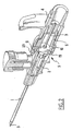
figure 1 est une vue en perspective du dispositif dans laquelle le cathéter court avec son embase, l'aiguille, les deux parties de la cage et l'organe de retenue coulissant ont été représentés séparés ; - les
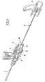
figures 2 et3 représentent le dispositif prêt pour l'emploi, respectivement en perspective avec arrachement et en coupe axiale ; - les
figures 4 et5 représentent le dispositif, respectivement en perspective avec arrachements et en coupe axiale, alors que la pointe de l'aiguille est retirée dans la chambre de la cage ; - les
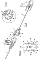
figures 6 et7 représentent le dispositif, respectivement en perspective avec arrachements et en coupe axiale, alors que l'organe de retenue est en cours de soulèvement ; - la
figure 8 est une vue agrandie d'un détail de lafigure 6 ; - les
figures 9 et10 représentent le dispositif, respectivement en perspective avec arrachements et en coupe axiale, alors que la cage est détachée de l'embase du cathéter ; - la
figure 11 est une vue agrandie d'un détail de lafigure 9 , et - la
figure 12 est une vue en plan de la paroi transversale de la pièce avant masquée en partie par la paroi coulissante de l'organe de retenue.
- the
figure 1 is a perspective view of the device in which the catheter runs with its base, the needle, the two parts of the cage and the sliding retainer have been shown separately; - the
figures 2 and3 represent the device ready for use, respectively in perspective cutaway and in axial section; - the
figures 4 and5 represent the device, respectively in perspective cutaway and in axial section, while the tip of the needle is withdrawn in the chamber of the cage; - the
figures 6 and7 represent the device, respectively in perspective cutaway and in axial section, while the retaining member is being lifted; - the
figure 8 is an enlarged view of a detail of thefigure 6 ; - the
figures 9 and10 represent the device, respectively in perspective cutaway and in axial section, while the cage is detached from the base of the catheter; - the
figure 11 is an enlarged view of a detail of thefigure 9 , and - the
figure 12 is a plan view of the transverse wall of the front piece partially hidden by the sliding wall of the retaining member.
Le dispositif représenté sur les figures comprend :
- un cathéter court tubulaire (1) muni d'une embase proximale (2) ;
- une aiguille (3) qui présente une extrémité de ponction (3a) et qui est munie d'une embase proximale (4) ;
- une cage (5) constituée d'une pièce arrière (6) et d'une pièce avant (7) ;
- un organe de retenue mobile (8).
- a short tubular catheter (1) provided with a proximal hub (2);
- a needle (3) which has a puncture end (3a) and which is provided with a proximal base (4);
- a cage (5) consisting of a rear piece (6) and a front piece (7);
- a movable retaining member (8).
L'organe de retenue est un corps moulé qui présente deux parois (9 ; 10) disposées à l'équerre. L'une des parois (9) se termine par un bec (11) et l'autre paroi (10), qui est percée d'un trou (12) pour le passage de l'aiguille.The retaining member is a molded body which has two walls (9; 10) arranged at right angles. One of the walls (9) ends with a spout (11) and the other wall (10), which is pierced with a hole (12) for the passage of the needle.
La pièce arrière (6) de la cage détermine une chambre (13) pour le passage de l'aiguille à travers la cage et détermine l'entrée (14) de cette chambre tandis que la pièce avant (7) de la cage détermine une paroi transversale (15) pour fermer la chambre, cette paroi étant percée d'un trou (16) qui constitue la sortie de la chambre. A l'avant de cette paroi, la pièce avant (7) détermine un nez (17) apte à être reçu dans l'embase du cathéter.The rear part (6) of the cage determines a chamber (13) for the passage of the needle through the cage and determines the inlet (14) of this chamber while the front part (7) of the cage determines a transverse wall (15) for closing the chamber, this wall being pierced with a hole (16) which constitutes the outlet of the chamber. At the front of this wall, the front piece (7) determines a nose (17) adapted to be received in the base of the catheter.
La pièce arrière (6) de la cage est conformée pour que l'embase de l'aiguille s'emboîte sur la pièce arrière pour la ponction (
La paroi transversale (15) de la pièce avant présente des tétons latéraux (18) aptes à s'encliqueter dans des trous (19) de la paroi de la chambre de la pièce arrière pour la fixation des deux pièces.The transverse wall (15) of the front piece has lateral pins (18) able to snap into holes (19) in the wall of the chamber of the rear piece for fixing the two pieces.
Cette paroi transversale détermine également des glissières (20) pour le coulissement de la paroi (10) de l'organe de retenue.This transverse wall also determines slides (20) for sliding the wall (10) of the retaining member.
Enfin, cette paroi transversale est munie d'un téton (21) apte à être reçu dans une lumière oblongue (22) de la paroi coulissante (10) pour limiter le soulèvement de l'organe mobile.Finally, this transverse wall is provided with a pin (21) adapted to be received in an oblong slot (22) of the sliding wall (10) to limit the lifting of the movable member.
L'embase (2) du cathéter court présente à proximité de son entrée un rebord (23) par exemple une collerette externe continue ou discontinue, pour arrêter le bec (11) de la guillotine et ce bec présente une rampe (24) apte à glisser progressivement sur la collerette lorsque la cage est tirée en direction proximale (
Des moyens sont prévus pour empêcher que la guillotine revienne en position basse après être arrivée en position levée.Means are provided to prevent the guillotine returning to the low position after reaching the raised position.
Dans l'exemple représenté, ces moyens sont constitués par des pattes souples et élastiques (8) formées sur les côtés de la paroi coulissante (10) de l'organe mobile et qui sont contraintes par des rebords (25) de la paroi transversale (15) de la pièce avant (7) de la cage jusqu'à ce que ces pattes soient arrivées au dessus des rebords lors du soulèvement de la guillotine (
De préférence, des moyens sont également prévus, de façon en soi connue pour empêcher que l'extrémité de ponction de l'aiguille puisse sortir de la cage par l'entrée proximale de la chambre.Preferably, means are also provided, known per se to prevent the puncture end of the needle from coming out of the cage through the proximal inlet of the chamber.
On a proposé de relier la cage à l'embase de l'aiguille par une liaison déployable telle que à l'état déployée cette liaison ait une longueur inférieur à la longueur de l'aiguille (
On a également proposé de limiter l'entrée proximale de la cage à un simple trou pour le passage de l'aiguille et de munir l'aiguille d'un renflement local en sorte que le coulissement de l'aiguille en direction proximale soit arrêté par butée de ce renflement contre le pourtour du trou.It has also been proposed to limit the proximal entrance of the cage to a simple hole for the passage of the needle and to provide the needle with a local bulge so that the sliding of the needle in the proximal direction is stopped by stop of this bulge against the perimeter of the hole.
La présente invention ne porte pas en soi sur un choix particulier d'un tel dispositif et, pour l'exemple uniquement, on a représenté un dispositif constitué par une paroi transversale fixe (26) dans laquelle est percée l'entrée proximale (14) de la cage et par un renflement local (27) de la section droite de l'aiguille. Ce renflement n'a été représenté que sur certaines figures et de façon exagérée : il va de soi que ce renflement est conçu pour ne pas empêcher le glissement de l'aiguille dans la canule.The present invention does not in itself relate to a particular choice of such a device and, for the example only, there is shown a device constituted by a fixed transverse wall (26) in which is pierced the proximal inlet (14). of the cage and by a local bulge (27) of the right section of the needle. This bulge has been shown in some figures and exaggerated: it goes without saying that this bulge is designed not to prevent slippage of the needle in the cannula.
L'invention n'est pas limitée aux réalisations qui ont été décrites.The invention is not limited to the embodiments that have been described.
Claims (10)
- A device for placing in a vein a cannula made of a short catheter (1) with a proximal hub (2), this device comprising a needle (3) having a puncture end (3a) and a cage (5) which extends the hub of the cannula in a proximal direction, this cage determining a chamber (13) slidingly crossed by the needle from a proximal entry (14) to a distal exit (16) and fitted with a trap to hold back in the chamber the needle puncture end when the needle is extracted from the catheter hub, the cage and the hub being provided with holding means cooperating to ensure a temporary holding of the cage on the hub before the needle puncture end is trapped in the cage chamber, said holding means comprising an outer rim (23) formed on the hub and an outer mouth (11) provided on the cage to be held by this rim, the mouth being formed on a moveable member (9, 10) which has a wall (10) crossed by a hole (12) for passing the needle so that the needle passing in the hole keeps the mouth in a holding position, characterized in that said wall (10) is slidingly mounted in the cage chamber along a direction transverse to the needle between a holding low position and a release upper position such that when the needle is removed from the cage up to being recessed from said hole, the wall (10) which is not crossed by the needle can slide towards its upper position, which raises said mouth and enables the cage to be separated from the catheter hub, said rim (23) and/or said mouth (11) having a ramp (24) such that a backward movement of the cage in a proximal direction causes the raising of the mouth when the needle (3) does no longer cross said hole (12).
- The device according to claim 1, wherein said mouth (11) is formed at the end of a wall (9) of the holding member which is normal to the sliding wall (10).
- The device according to one of claims 1 to 2, and which comprises means (21; 22) for limiting the raising of the sliding wall in an upper position.
- The device according to one of claims 1 to 3, and which comprises means (8; 8) for preventing the moveable member from coming back in a low position after it has come in an upper position.
- The device according to one of claims 1 to 4, the cage (5) of which is formed by a rear piece (6) which makes up the chamber (13) and the entry (14) of the chamber and of a front piece (7) which comprises a transverse wall (15) which closes said chamber and which comprises the exit (16) of the chamber, this transverse wall (15) determining a slider for said sliding wall (10) of said holding member, both these pieces (6, 7) being kept assembled by snap fitting dog points (18) provided on the sides of the transverse wall of the front piece in holes (19) formed in the chamber wall of the rear piece, or conversely.
- The device according to claim 5, wherein the front piece (7) of the cage makes up at the front of said transverse wall (15) a nose (17) apt to be received in the catheter hub.
- The device according to one of claims 4 to 6, wherein said transverse wall (15) of the front piece (7) of the cage carries a dog point (21) which slides in an oblong port (22) of the sliding wall of the holding member to limit the raising of the moveable member.
- The device according to one of claims 4 to 7, and wherein said sliding wall (10) of the holding member has flexible elastic side legs (8, 8) which are constrained by rims (25) formed on the transverse wall (15) of the front piece (7) of the cage as long as said member has not reached the upper position and which expand, when the member reaches the upper position, to rest on these rims by preventing the member from coming back in the low position.
- The device according to one of claims 4 to 8, wherein the rear piece of the cage is shaped so that the needle hub engages the latter for the puncture.
- The device according to one of claims 1 to 9, and which comprises means (14, 27) for preventing the tip of the needle from being able to exit via the chamber entry.
Priority Applications (1)
| Application Number | Priority Date | Filing Date | Title |
|---|---|---|---|
| PL05733010T PL1720599T3 (en) | 2004-03-02 | 2005-03-02 | Device with a slidable safety member for positioning a cannula in a vein |
Applications Claiming Priority (2)
| Application Number | Priority Date | Filing Date | Title |
|---|---|---|---|
| FR0402121A FR2867081B1 (en) | 2004-03-02 | 2004-03-02 | SLIDING SAFETY DEVICE FOR PLACING A CANNULA INTO A VEIN |
| PCT/FR2005/000493 WO2005087306A1 (en) | 2004-03-02 | 2005-03-02 | Device with a slidable safety member for positioning a cannula in a vein |
Publications (2)
| Publication Number | Publication Date |
|---|---|
| EP1720599A1 EP1720599A1 (en) | 2006-11-15 |
| EP1720599B1 true EP1720599B1 (en) | 2015-09-16 |
Family
ID=34854968
Family Applications (1)
| Application Number | Title | Priority Date | Filing Date |
|---|---|---|---|
| EP05733010.2A Active EP1720599B1 (en) | 2004-03-02 | 2005-03-02 | Device with a slidable safety member for positioning a cannula in a vein |
Country Status (8)
| Country | Link |
|---|---|
| US (1) | US20070179446A1 (en) |
| EP (1) | EP1720599B1 (en) |
| JP (1) | JP2007526061A (en) |
| KR (1) | KR20070006819A (en) |
| ES (1) | ES2553728T3 (en) |
| FR (1) | FR2867081B1 (en) |
| PL (1) | PL1720599T3 (en) |
| WO (1) | WO2005087306A1 (en) |
Families Citing this family (50)
| Publication number | Priority date | Publication date | Assignee | Title |
|---|---|---|---|---|
| US6749588B1 (en) | 1998-04-09 | 2004-06-15 | Becton Dickinson And Company | Catheter and introducer needle assembly with needle shield |
| WO2007006055A2 (en) | 2005-07-06 | 2007-01-11 | Vascular Pathways Inc. | Intravenous catheter insertion device and method of use |
| US7632243B2 (en) * | 2005-08-08 | 2009-12-15 | Smiths Medical Asd, Inc. | Duckbill catheter release mechanism |
| US20070038187A1 (en) | 2005-08-08 | 2007-02-15 | Albert Sean J | Needle guard mechanism with anti-rotation feature |
| US7733659B2 (en) * | 2006-08-18 | 2010-06-08 | Delphi Technologies, Inc. | Lightweight audio system for automotive applications and method |
| JP4994775B2 (en) | 2006-10-12 | 2012-08-08 | 日本コヴィディエン株式会社 | Needle point protector |
| WO2008137956A2 (en) | 2007-05-07 | 2008-11-13 | Vascular Pathways, Inc. | Intravenous catheter insertion and blood sample devices and method of use |
| ATE504248T1 (en) | 2007-08-01 | 2011-04-15 | Tradinco Ab | PERIPHERAL CATHETER ARRANGEMENT WITH HEMOSTASIS VALVE |
| US7713243B2 (en) * | 2007-09-25 | 2010-05-11 | Becton, Dickinson And Company | Tip shield for needle stick prevention |
| NZ585519A (en) | 2007-11-21 | 2012-10-26 | Becton Dickinson Co | A needle guard with a pivoting arm with a needle tip sensing element |
| US8298180B2 (en) | 2007-11-21 | 2012-10-30 | Becton, Dickinson And Company | Safety needle guard |
| US8858503B2 (en) * | 2007-12-21 | 2014-10-14 | Becton, Dickinson And Company | Tip shield with gripping surfaces and guard features |
| US7828774B2 (en) * | 2008-05-12 | 2010-11-09 | Harding Weston F | Sleeved clip safety |
| US8439877B2 (en) * | 2009-03-02 | 2013-05-14 | Becton, Dickinson And Company | Bi-directionally engageable cannula crimp feature |
| US9399120B2 (en) | 2009-03-02 | 2016-07-26 | Becton, Dickinson And Company | Bi-directional cannula feature capture mechanism |
| US8496623B2 (en) * | 2009-03-02 | 2013-07-30 | Becton, Dickinson And Company | Bi-directional cannula feature capture mechanism |
| US8936575B2 (en) * | 2009-03-19 | 2015-01-20 | Becton, Dickinson And Company | Cannula-tip shielding mechanism |
| US20100305519A1 (en) * | 2009-06-02 | 2010-12-02 | Becton, Dickinson And Company | Cannula having an overlapping cannula feature and notch feature |
| US8474300B2 (en) * | 2009-07-20 | 2013-07-02 | Becton, Dickinson And Company | Methods to provide a feature on a needle |
| US8323249B2 (en) | 2009-08-14 | 2012-12-04 | The Regents Of The University Of Michigan | Integrated vascular delivery system |
| US11925779B2 (en) | 2010-05-14 | 2024-03-12 | C. R. Bard, Inc. | Catheter insertion device including top-mounted advancement components |
| US10384039B2 (en) | 2010-05-14 | 2019-08-20 | C. R. Bard, Inc. | Catheter insertion device including top-mounted advancement components |
| US9950139B2 (en) | 2010-05-14 | 2018-04-24 | C. R. Bard, Inc. | Catheter placement device including guidewire and catheter control elements |
| US8932258B2 (en) | 2010-05-14 | 2015-01-13 | C. R. Bard, Inc. | Catheter placement device and method |
| US9872971B2 (en) | 2010-05-14 | 2018-01-23 | C. R. Bard, Inc. | Guidewire extension system for a catheter placement device |
| WO2011146769A2 (en) | 2010-05-19 | 2011-11-24 | Tangent Medical Technologies Llc | Integrated vascular delivery system |
| US8814833B2 (en) | 2010-05-19 | 2014-08-26 | Tangent Medical Technologies Llc | Safety needle system operable with a medical device |
| US8690833B2 (en) | 2011-01-31 | 2014-04-08 | Vascular Pathways, Inc. | Intravenous catheter and insertion device with reduced blood spatter |
| CN103379937B (en) | 2011-02-25 | 2016-09-07 | C·R·巴德股份有限公司 | Medical component insertion device including retractible pin |
| EP2517751B8 (en) | 2011-04-27 | 2018-02-28 | Kpr U.S., Llc | Safety IV catheter assemblies |
| USD903101S1 (en) | 2011-05-13 | 2020-11-24 | C. R. Bard, Inc. | Catheter |
| WO2013048975A1 (en) | 2011-09-26 | 2013-04-04 | Covidien Lp | Safety catheter |
| EP2760521B1 (en) | 2011-09-26 | 2016-01-06 | Covidien LP | Safety iv catheter and needle assembly |
| US9155876B2 (en) * | 2011-10-06 | 2015-10-13 | Becton, Dickinson And Company | Port valve of a blood control catheter |
| US8834422B2 (en) | 2011-10-14 | 2014-09-16 | Covidien Lp | Vascular access assembly and safety device |
| AU2012379922B2 (en) * | 2012-05-16 | 2017-07-20 | Mitsubishi Pencil Company, Limited | Catheter assembly |
| WO2014120741A1 (en) | 2013-01-30 | 2014-08-07 | Vascular Pathways, Inc. | Systems and methods for venipuncture and catheter placement |
| WO2015119940A1 (en) | 2014-02-04 | 2015-08-13 | Icu Medical, Inc. | Self-priming systems and methods |
| US9555221B2 (en) | 2014-04-10 | 2017-01-31 | Smiths Medical Asd, Inc. | Constant force hold tip protector for a safety catheter |
| US10232146B2 (en) | 2014-09-05 | 2019-03-19 | C. R. Bard, Inc. | Catheter insertion device including retractable needle |
| USD903100S1 (en) | 2015-05-01 | 2020-11-24 | C. R. Bard, Inc. | Catheter placement device |
| JP7016261B2 (en) | 2015-05-15 | 2022-02-21 | シー・アール・バード・インコーポレーテッド | Catheter indwelling device with extendable needle safety component |
| JP7051821B2 (en) | 2016-09-12 | 2022-04-11 | シー・アール・バード・インコーポレーテッド | Blood control for catheter insertion device |
| CA3054969A1 (en) | 2017-03-01 | 2018-09-07 | C.R. Bard, Inc. | Catheter insertion device |
| WO2019173641A1 (en) | 2018-03-07 | 2019-09-12 | Bard Access Systems, Inc. | Guidewire advancement and blood flashback systems for a medical device insertion system |
| USD921884S1 (en) | 2018-07-27 | 2021-06-08 | Bard Access Systems, Inc. | Catheter insertion device |
| BR112022003173A2 (en) | 2019-08-19 | 2022-05-17 | Becton Dickinson Co | Midline catheter placement device |
| CN213252024U (en) * | 2019-09-10 | 2021-05-25 | 贝克顿·迪金森公司 | Vascular access system and clamping device |
| CN114431859A (en) * | 2020-11-06 | 2022-05-06 | 贝克顿·迪金森公司 | Blood collection devices, systems, and methods |
| CN114469282B (en) * | 2022-03-31 | 2022-07-01 | 真健康(北京)医疗科技有限公司 | Orthogonal structure five-degree-of-freedom puncture robot |
Citations (4)
| Publication number | Priority date | Publication date | Assignee | Title |
|---|---|---|---|---|
| WO1996022800A1 (en) * | 1995-01-23 | 1996-08-01 | Graphic Controls Corporation | Safety catheter |
| US5573510A (en) * | 1994-02-28 | 1996-11-12 | Isaacson; Dennis R. | Safety intravenous catheter assembly with automatically retractable needle |
| EP0747083A2 (en) * | 1995-06-07 | 1996-12-11 | JOHNSON & JOHNSON MEDICAL, INC. | Catheter needle locking and catheter hub unlocking mechanism |
| US6749588B1 (en) * | 1998-04-09 | 2004-06-15 | Becton Dickinson And Company | Catheter and introducer needle assembly with needle shield |
Family Cites Families (13)
| Publication number | Priority date | Publication date | Assignee | Title |
|---|---|---|---|---|
| US4900307A (en) * | 1987-04-29 | 1990-02-13 | Kulli John C | Safety retracting needle for use with syringe |
| US5279591A (en) * | 1990-07-16 | 1994-01-18 | Simon Alexander Z | Protector for needle catheter |
| US5300045A (en) * | 1993-04-14 | 1994-04-05 | Plassche Jr Walter M | Interventional needle having an automatically capping stylet |
| CA2135706C (en) * | 1993-11-15 | 1999-06-15 | Walter E. Cover | Retractable-needle cannula insertion set with refinements to better control leakage, retraction speed, and reuse |
| EP0763369B1 (en) * | 1995-09-18 | 2002-01-09 | Becton, Dickinson and Company | Needle shield with collapsible cover |
| GB9605206D0 (en) * | 1996-03-12 | 1996-05-15 | Boc Group Plc | Medical devices |
| EP0832666A3 (en) * | 1996-09-30 | 1998-08-26 | Becton, Dickinson and Company | Detachable blood seal |
| US6077244A (en) * | 1998-04-30 | 2000-06-20 | Mdc Investment Holdings, Inc. | Catheter insertion device with retractable needle |
| EP1378263A3 (en) * | 1998-07-31 | 2005-11-16 | MDC Investment Holding, Inc. | Retractable needle medical device |
| US6221047B1 (en) * | 1998-07-31 | 2001-04-24 | Albany Medical College | Safety intravenous catheter assembly and method for use with a needle |
| US6796962B2 (en) * | 2001-03-15 | 2004-09-28 | Specialized Health Products, Inc. | Safety shield for medical needles |
| US6595955B2 (en) * | 2001-03-15 | 2003-07-22 | Specialized Health Products, Inc. | Safety shield for medical needles |
| TWI238070B (en) * | 2003-11-07 | 2005-08-21 | Ming-Jeng Shiu | Medical appliances |
-
2004
- 2004-03-02 FR FR0402121A patent/FR2867081B1/en not_active Expired - Lifetime
-
2005
- 2005-03-02 WO PCT/FR2005/000493 patent/WO2005087306A1/en active Application Filing
- 2005-03-02 JP JP2007501309A patent/JP2007526061A/en active Pending
- 2005-03-02 ES ES05733010.2T patent/ES2553728T3/en active Active
- 2005-03-02 KR KR1020067020455A patent/KR20070006819A/en not_active Application Discontinuation
- 2005-03-02 EP EP05733010.2A patent/EP1720599B1/en active Active
- 2005-03-02 PL PL05733010T patent/PL1720599T3/en unknown
- 2005-03-02 US US10/598,432 patent/US20070179446A1/en not_active Abandoned
Patent Citations (4)
| Publication number | Priority date | Publication date | Assignee | Title |
|---|---|---|---|---|
| US5573510A (en) * | 1994-02-28 | 1996-11-12 | Isaacson; Dennis R. | Safety intravenous catheter assembly with automatically retractable needle |
| WO1996022800A1 (en) * | 1995-01-23 | 1996-08-01 | Graphic Controls Corporation | Safety catheter |
| EP0747083A2 (en) * | 1995-06-07 | 1996-12-11 | JOHNSON & JOHNSON MEDICAL, INC. | Catheter needle locking and catheter hub unlocking mechanism |
| US6749588B1 (en) * | 1998-04-09 | 2004-06-15 | Becton Dickinson And Company | Catheter and introducer needle assembly with needle shield |
Also Published As
| Publication number | Publication date |
|---|---|
| EP1720599A1 (en) | 2006-11-15 |
| ES2553728T3 (en) | 2015-12-11 |
| WO2005087306A1 (en) | 2005-09-22 |
| FR2867081B1 (en) | 2006-05-26 |
| JP2007526061A (en) | 2007-09-13 |
| PL1720599T3 (en) | 2016-01-29 |
| KR20070006819A (en) | 2007-01-11 |
| FR2867081A1 (en) | 2005-09-09 |
| US20070179446A1 (en) | 2007-08-02 |
Similar Documents
| Publication | Publication Date | Title |
|---|---|---|
| EP1720599B1 (en) | Device with a slidable safety member for positioning a cannula in a vein | |
| EP1720588B1 (en) | Drooped hook device for placing a cannula in a vein | |
| EP1737529B1 (en) | Device for introducing a catheter with a security non-piercing cage provided with a flexible blade | |
| EP0925763B1 (en) | Assembly for placing an implant into an internal body conduit | |
| FR2718345A1 (en) | Handle for controlled relative sliding of a sheath and a shaft and apparatus for implanting a medical device, such as a filter, using such a handle. | |
| EP2170448B1 (en) | Device for introducing a catheter guide wire into a vessel | |
| EP1027902B1 (en) | Autoprotected injection syringe | |
| EP1436026B1 (en) | Safety device for a syringe | |
| EP0475857B1 (en) | Needle assembly for medical use | |
| EP1786497B1 (en) | Injection device comprising a syringe | |
| FR2770404A1 (en) | AUTOMATIC INJECTOR WITH NEEDLE RETRACTION AT THE END OF INJECTION | |
| EP0825883A1 (en) | Reloadable auto-injector | |
| WO2006123046A1 (en) | Kit for inserting a cavity-treatment element and method of preparing an associated treatment element | |
| FR2710541A1 (en) | Together for the introduction of a catheter. | |
| FR2710540A1 (en) | Together for the introduction of a catheter. | |
| EP2493545B1 (en) | Needle stick guard, and puncturing kit including such a needle stick guard | |
| EP3644909B1 (en) | Handle for delivering a stent and device comprising the handle | |
| EP1622671B1 (en) | Assembly comprising an aspirating needle and a needle protector tube, and application thereof | |
| WO2001028612A1 (en) | Syringe comprising a needle-protecting sleeve | |
| FR3129842A1 (en) | Safety Medical Needle Set | |
| WO1994005362A1 (en) | Device for introducing a catheter into the human body | |
| FR2783716A1 (en) | PROTECTIVE DEVICE FOR THE CANNULA OR NEEDLE OF AN INJECTION SYRINGE | |
| WO1994005362A9 (en) | Device for introducing a catheter into the human body | |
| FR2893507A1 (en) | Medical needle e.g. gripper, extracting device for medical environment, has pins clipped in holes to lock inner body in upper position, where body has base conformed to permit capture and extraction of needle planted in implantable chamber |
Legal Events
| Date | Code | Title | Description |
|---|---|---|---|
| PUAI | Public reference made under article 153(3) epc to a published international application that has entered the european phase |
Free format text: ORIGINAL CODE: 0009012 |
|
| 17P | Request for examination filed |
Effective date: 20060830 |
|
| AK | Designated contracting states |
Kind code of ref document: A1 Designated state(s): AT BE BG CH CY CZ DE DK EE ES FI FR GB GR HU IE IS IT LI LT LU MC NL PL PT RO SE SI SK TR |
|
| DAX | Request for extension of the european patent (deleted) | ||
| 17Q | First examination report despatched |
Effective date: 20080910 |
|
| RAP3 | Party data changed (applicant data changed or rights of an application transferred) |
Owner name: VYGON S.A. |
|
| RAP3 | Party data changed (applicant data changed or rights of an application transferred) |
Owner name: VYGON |
|
| GRAP | Despatch of communication of intention to grant a patent |
Free format text: ORIGINAL CODE: EPIDOSNIGR1 |
|
| INTG | Intention to grant announced |
Effective date: 20150410 |
|
| GRAS | Grant fee paid |
Free format text: ORIGINAL CODE: EPIDOSNIGR3 |
|
| GRAA | (expected) grant |
Free format text: ORIGINAL CODE: 0009210 |
|
| AK | Designated contracting states |
Kind code of ref document: B1 Designated state(s): AT BE BG CH CY CZ DE DK EE ES FI FR GB GR HU IE IS IT LI LT LU MC NL PL PT RO SE SI SK TR |
|
| REG | Reference to a national code |
Ref country code: GB Ref legal event code: FG4D Free format text: NOT ENGLISH |
|
| REG | Reference to a national code |
Ref country code: CH Ref legal event code: EP |
|
| REG | Reference to a national code |
Ref country code: IE Ref legal event code: FG4D Free format text: LANGUAGE OF EP DOCUMENT: FRENCH |
|
| REG | Reference to a national code |
Ref country code: AT Ref legal event code: REF Ref document number: 749294 Country of ref document: AT Kind code of ref document: T Effective date: 20151015 |
|
| REG | Reference to a national code |
Ref country code: DE Ref legal event code: R096 Ref document number: 602005047505 Country of ref document: DE |
|
| REG | Reference to a national code |
Ref country code: ES Ref legal event code: FG2A Ref document number: 2553728 Country of ref document: ES Kind code of ref document: T3 Effective date: 20151211 |
|
| PG25 | Lapsed in a contracting state [announced via postgrant information from national office to epo] |
Ref country code: FI Free format text: LAPSE BECAUSE OF FAILURE TO SUBMIT A TRANSLATION OF THE DESCRIPTION OR TO PAY THE FEE WITHIN THE PRESCRIBED TIME-LIMIT Effective date: 20150916 Ref country code: LT Free format text: LAPSE BECAUSE OF FAILURE TO SUBMIT A TRANSLATION OF THE DESCRIPTION OR TO PAY THE FEE WITHIN THE PRESCRIBED TIME-LIMIT Effective date: 20150916 Ref country code: GR Free format text: LAPSE BECAUSE OF FAILURE TO SUBMIT A TRANSLATION OF THE DESCRIPTION OR TO PAY THE FEE WITHIN THE PRESCRIBED TIME-LIMIT Effective date: 20151217 |
|
| REG | Reference to a national code |
Ref country code: LT Ref legal event code: MG4D Ref country code: NL Ref legal event code: FP |
|
| REG | Reference to a national code |
Ref country code: AT Ref legal event code: MK05 Ref document number: 749294 Country of ref document: AT Kind code of ref document: T Effective date: 20150916 |
|
| PG25 | Lapsed in a contracting state [announced via postgrant information from national office to epo] |
Ref country code: SE Free format text: LAPSE BECAUSE OF FAILURE TO SUBMIT A TRANSLATION OF THE DESCRIPTION OR TO PAY THE FEE WITHIN THE PRESCRIBED TIME-LIMIT Effective date: 20150916 |
|
| REG | Reference to a national code |
Ref country code: FR Ref legal event code: PLFP Year of fee payment: 12 |
|
| PG25 | Lapsed in a contracting state [announced via postgrant information from national office to epo] |
Ref country code: EE Free format text: LAPSE BECAUSE OF FAILURE TO SUBMIT A TRANSLATION OF THE DESCRIPTION OR TO PAY THE FEE WITHIN THE PRESCRIBED TIME-LIMIT Effective date: 20150916 Ref country code: SK Free format text: LAPSE BECAUSE OF FAILURE TO SUBMIT A TRANSLATION OF THE DESCRIPTION OR TO PAY THE FEE WITHIN THE PRESCRIBED TIME-LIMIT Effective date: 20150916 Ref country code: CZ Free format text: LAPSE BECAUSE OF FAILURE TO SUBMIT A TRANSLATION OF THE DESCRIPTION OR TO PAY THE FEE WITHIN THE PRESCRIBED TIME-LIMIT Effective date: 20150916 Ref country code: IS Free format text: LAPSE BECAUSE OF FAILURE TO SUBMIT A TRANSLATION OF THE DESCRIPTION OR TO PAY THE FEE WITHIN THE PRESCRIBED TIME-LIMIT Effective date: 20160116 |
|
| PG25 | Lapsed in a contracting state [announced via postgrant information from national office to epo] |
Ref country code: RO Free format text: LAPSE BECAUSE OF FAILURE TO SUBMIT A TRANSLATION OF THE DESCRIPTION OR TO PAY THE FEE WITHIN THE PRESCRIBED TIME-LIMIT Effective date: 20150916 Ref country code: AT Free format text: LAPSE BECAUSE OF FAILURE TO SUBMIT A TRANSLATION OF THE DESCRIPTION OR TO PAY THE FEE WITHIN THE PRESCRIBED TIME-LIMIT Effective date: 20150916 Ref country code: PT Free format text: LAPSE BECAUSE OF FAILURE TO SUBMIT A TRANSLATION OF THE DESCRIPTION OR TO PAY THE FEE WITHIN THE PRESCRIBED TIME-LIMIT Effective date: 20160118 |
|
| REG | Reference to a national code |
Ref country code: DE Ref legal event code: R097 Ref document number: 602005047505 Country of ref document: DE |
|
| PLBE | No opposition filed within time limit |
Free format text: ORIGINAL CODE: 0009261 |
|
| STAA | Information on the status of an ep patent application or granted ep patent |
Free format text: STATUS: NO OPPOSITION FILED WITHIN TIME LIMIT |
|
| 26N | No opposition filed |
Effective date: 20160617 |
|
| PG25 | Lapsed in a contracting state [announced via postgrant information from national office to epo] |
Ref country code: DK Free format text: LAPSE BECAUSE OF FAILURE TO SUBMIT A TRANSLATION OF THE DESCRIPTION OR TO PAY THE FEE WITHIN THE PRESCRIBED TIME-LIMIT Effective date: 20150916 |
|
| PG25 | Lapsed in a contracting state [announced via postgrant information from national office to epo] |
Ref country code: MC Free format text: LAPSE BECAUSE OF FAILURE TO SUBMIT A TRANSLATION OF THE DESCRIPTION OR TO PAY THE FEE WITHIN THE PRESCRIBED TIME-LIMIT Effective date: 20150916 Ref country code: LU Free format text: LAPSE BECAUSE OF FAILURE TO SUBMIT A TRANSLATION OF THE DESCRIPTION OR TO PAY THE FEE WITHIN THE PRESCRIBED TIME-LIMIT Effective date: 20160302 |
|
| REG | Reference to a national code |
Ref country code: CH Ref legal event code: PL |
|
| PG25 | Lapsed in a contracting state [announced via postgrant information from national office to epo] |
Ref country code: SI Free format text: LAPSE BECAUSE OF FAILURE TO SUBMIT A TRANSLATION OF THE DESCRIPTION OR TO PAY THE FEE WITHIN THE PRESCRIBED TIME-LIMIT Effective date: 20150916 |
|
| REG | Reference to a national code |
Ref country code: IE Ref legal event code: MM4A |
|
| PG25 | Lapsed in a contracting state [announced via postgrant information from national office to epo] |
Ref country code: LI Free format text: LAPSE BECAUSE OF NON-PAYMENT OF DUE FEES Effective date: 20160331 Ref country code: CH Free format text: LAPSE BECAUSE OF NON-PAYMENT OF DUE FEES Effective date: 20160331 Ref country code: IE Free format text: LAPSE BECAUSE OF NON-PAYMENT OF DUE FEES Effective date: 20160302 |
|
| REG | Reference to a national code |
Ref country code: FR Ref legal event code: PLFP Year of fee payment: 13 |
|
| REG | Reference to a national code |
Ref country code: FR Ref legal event code: PLFP Year of fee payment: 14 |
|
| PG25 | Lapsed in a contracting state [announced via postgrant information from national office to epo] |
Ref country code: HU Free format text: LAPSE BECAUSE OF FAILURE TO SUBMIT A TRANSLATION OF THE DESCRIPTION OR TO PAY THE FEE WITHIN THE PRESCRIBED TIME-LIMIT; INVALID AB INITIO Effective date: 20050302 Ref country code: CY Free format text: LAPSE BECAUSE OF FAILURE TO SUBMIT A TRANSLATION OF THE DESCRIPTION OR TO PAY THE FEE WITHIN THE PRESCRIBED TIME-LIMIT Effective date: 20150916 |
|
| PG25 | Lapsed in a contracting state [announced via postgrant information from national office to epo] |
Ref country code: TR Free format text: LAPSE BECAUSE OF FAILURE TO SUBMIT A TRANSLATION OF THE DESCRIPTION OR TO PAY THE FEE WITHIN THE PRESCRIBED TIME-LIMIT Effective date: 20150916 |
|
| PG25 | Lapsed in a contracting state [announced via postgrant information from national office to epo] |
Ref country code: BG Free format text: LAPSE BECAUSE OF FAILURE TO SUBMIT A TRANSLATION OF THE DESCRIPTION OR TO PAY THE FEE WITHIN THE PRESCRIBED TIME-LIMIT Effective date: 20150916 |
|
| PGFP | Annual fee paid to national office [announced via postgrant information from national office to epo] |
Ref country code: NL Payment date: 20230227 Year of fee payment: 19 |
|
| PGFP | Annual fee paid to national office [announced via postgrant information from national office to epo] |
Ref country code: FR Payment date: 20230216 Year of fee payment: 19 |
|
| PGFP | Annual fee paid to national office [announced via postgrant information from national office to epo] |
Ref country code: PL Payment date: 20230220 Year of fee payment: 19 Ref country code: IT Payment date: 20230307 Year of fee payment: 19 Ref country code: GB Payment date: 20230324 Year of fee payment: 19 Ref country code: DE Payment date: 20230307 Year of fee payment: 19 Ref country code: BE Payment date: 20230316 Year of fee payment: 19 |
|
| P01 | Opt-out of the competence of the unified patent court (upc) registered |
Effective date: 20230428 |
|
| PGFP | Annual fee paid to national office [announced via postgrant information from national office to epo] |
Ref country code: ES Payment date: 20230405 Year of fee payment: 19 |
|
| PGFP | Annual fee paid to national office [announced via postgrant information from national office to epo] |
Ref country code: NL Payment date: 20240226 Year of fee payment: 20 |