EP1719630A1 - Roll sheet holder and tape printer - Google Patents
Roll sheet holder and tape printer Download PDFInfo
- Publication number
- EP1719630A1 EP1719630A1 EP06017570A EP06017570A EP1719630A1 EP 1719630 A1 EP1719630 A1 EP 1719630A1 EP 06017570 A EP06017570 A EP 06017570A EP 06017570 A EP06017570 A EP 06017570A EP 1719630 A1 EP1719630 A1 EP 1719630A1
- Authority
- EP
- European Patent Office
- Prior art keywords
- roll sheet
- tape printer
- holder
- positioning
- sheet
- Prior art date
- Legal status (The legal status is an assumption and is not a legal conclusion. Google has not performed a legal analysis and makes no representation as to the accuracy of the status listed.)
- Granted
Links
Images


Classifications
-
- B—PERFORMING OPERATIONS; TRANSPORTING
- B41—PRINTING; LINING MACHINES; TYPEWRITERS; STAMPS
- B41J—TYPEWRITERS; SELECTIVE PRINTING MECHANISMS, i.e. MECHANISMS PRINTING OTHERWISE THAN FROM A FORME; CORRECTION OF TYPOGRAPHICAL ERRORS
- B41J15/00—Devices or arrangements of selective printing mechanisms, e.g. ink-jet printers or thermal printers, specially adapted for supporting or handling copy material in continuous form, e.g. webs
- B41J15/04—Supporting, feeding, or guiding devices; Mountings for web rolls or spindles
-
- B—PERFORMING OPERATIONS; TRANSPORTING
- B41—PRINTING; LINING MACHINES; TYPEWRITERS; STAMPS
- B41J—TYPEWRITERS; SELECTIVE PRINTING MECHANISMS, i.e. MECHANISMS PRINTING OTHERWISE THAN FROM A FORME; CORRECTION OF TYPOGRAPHICAL ERRORS
- B41J15/00—Devices or arrangements of selective printing mechanisms, e.g. ink-jet printers or thermal printers, specially adapted for supporting or handling copy material in continuous form, e.g. webs
- B41J15/02—Web rolls or spindles; Attaching webs to cores or spindles
-
- B—PERFORMING OPERATIONS; TRANSPORTING
- B41—PRINTING; LINING MACHINES; TYPEWRITERS; STAMPS
- B41J—TYPEWRITERS; SELECTIVE PRINTING MECHANISMS, i.e. MECHANISMS PRINTING OTHERWISE THAN FROM A FORME; CORRECTION OF TYPOGRAPHICAL ERRORS
- B41J15/00—Devices or arrangements of selective printing mechanisms, e.g. ink-jet printers or thermal printers, specially adapted for supporting or handling copy material in continuous form, e.g. webs
- B41J15/04—Supporting, feeding, or guiding devices; Mountings for web rolls or spindles
- B41J15/042—Supporting, feeding, or guiding devices; Mountings for web rolls or spindles for loading rolled-up continuous copy material into printers, e.g. for replacing a used-up paper roll; Point-of-sale printers with openable casings allowing access to the rolled-up continuous copy material
-
- B—PERFORMING OPERATIONS; TRANSPORTING
- B41—PRINTING; LINING MACHINES; TYPEWRITERS; STAMPS
- B41J—TYPEWRITERS; SELECTIVE PRINTING MECHANISMS, i.e. MECHANISMS PRINTING OTHERWISE THAN FROM A FORME; CORRECTION OF TYPOGRAPHICAL ERRORS
- B41J15/00—Devices or arrangements of selective printing mechanisms, e.g. ink-jet printers or thermal printers, specially adapted for supporting or handling copy material in continuous form, e.g. webs
- B41J15/04—Supporting, feeding, or guiding devices; Mountings for web rolls or spindles
- B41J15/046—Supporting, feeding, or guiding devices; Mountings for web rolls or spindles for the guidance of continuous copy material, e.g. for preventing skewed conveyance of the continuous copy material
-
- B—PERFORMING OPERATIONS; TRANSPORTING
- B41—PRINTING; LINING MACHINES; TYPEWRITERS; STAMPS
- B41J—TYPEWRITERS; SELECTIVE PRINTING MECHANISMS, i.e. MECHANISMS PRINTING OTHERWISE THAN FROM A FORME; CORRECTION OF TYPOGRAPHICAL ERRORS
- B41J3/00—Typewriters or selective printing or marking mechanisms characterised by the purpose for which they are constructed
- B41J3/407—Typewriters or selective printing or marking mechanisms characterised by the purpose for which they are constructed for marking on special material
- B41J3/4075—Tape printers; Label printers
-
- Y—GENERAL TAGGING OF NEW TECHNOLOGICAL DEVELOPMENTS; GENERAL TAGGING OF CROSS-SECTIONAL TECHNOLOGIES SPANNING OVER SEVERAL SECTIONS OF THE IPC; TECHNICAL SUBJECTS COVERED BY FORMER USPC CROSS-REFERENCE ART COLLECTIONS [XRACs] AND DIGESTS
- Y10—TECHNICAL SUBJECTS COVERED BY FORMER USPC
- Y10S—TECHNICAL SUBJECTS COVERED BY FORMER USPC CROSS-REFERENCE ART COLLECTIONS [XRACs] AND DIGESTS
- Y10S242/00—Winding, tensioning, or guiding
- Y10S242/912—Indicator or alarm
Definitions
- the present invention relates to a roll sheet holder which rotatably holds a roll sheet wound on a cylindrical sheet core and is removably mounted in a tape printer provided with a feeding device for feeding the roll sheet and a printing unit for printing on the roll sheet. Further, the present invention relates to a tape printer in which the roll sheet holder is removably mounted.
- Some tape printers of this type are provided with a roll sheet wound on a sheet core, a roll sheet holder which rotatably holds therein the sheet core, a support mechanism which removably mounts the roll sheet holder in the tape printer, and a feeding device for feeding part of the roll sheet while drawing the roll sheet from the roll sheet holder.
- the roll sheet holder may be selected from among plural holders of different sizes individually corresponding to various sheet widths.
- This holding case is constructed of a mechanism for supporting both ends of the sheet core, a recording sheet drawing port through which part of the thermal recording sheet is unwound, and pits and projections formed on an outer surface of the case to indicate the kind of thermal recording sheet stored in the case.
- the tape printer using the recording sheet holding case constructed as above can distinguish the kind of thermal recording sheet stored in the sheet holding case by means of a microswitch or the like provided in the bottom of the sheet holding case and thereby control the application of electric power to a thermal head. Accordingly, images can be printed at an appropriate color density on the thermal recording sheet mounted in the printer.
- the conventional tape printer in which the above mentioned recording sheet holding case is mounted has the following disadvantages.
- the holding case When part of the thermal recording sheet is unwound, the holding case is caused to rotate in a direction of drawing of the sheet. Accordingly, lower end faces of the projections of the holding case whereby the microswitch is pressed down are moved up to come off the microswitch. This may cause a problem that images are printed at an inappropriate color density on the thermal recording sheet.
- the present invention has been made in view of the above circumstances and has an object to overcome the above problems and to provide a roll sheet holder which can be prevented from rotating in a direction of drawing a roll sheet from the holder to hold a bottom of the roll sheet holder against upward dislocation.
- a roll sheet holder which holds a roll sheet wound on a cylindrical sheet core having a through hole opening at both ends and is removably mountable in a tape printer which includes a feeding device which draws the roll sheet to feed an unwound part thereof, a printing device which prints on the part of the roll sheet fed by the feeding device
- the roll sheet holder comprises: a guide member including a first flange part arranged in contact with one end face of the roll sheet; and a positioning holding member arranged in contact with the other end face of the roll sheet;
- the roll sheet holder is mountable in the tape printer which includes an insertion opening in which the unwound part of the roll sheet is inserted and a support portion provided upstream of the insertion opening in a direction of feeding the unwound part of the roll sheet;
- the first flange part includes: a first extended portion extending downward in a predetermined length, which is brought into contact with a bottom surface of the tape printer when the roll sheet holder is mounted there
- one end of the sheet core on which the roll sheet is wound is fixed to the first flange part so that one end face of the roll sheet is held in contact with the first flange part.
- the lower edge of the frontward extended portion of the first flange part is brought into contact with the upper surface of the support portion provided upstream of the insertion opening in which the unwound part of the roll sheet is to be inserted.
- the roll sheet is drawn from above the sheet core and inserted in the insertion opening.
- the roll sheet holder With the frontward extended portion whose lower edge is in contact with the upper surface of the support portion, the roll sheet holder can be prevented from rotating in a direction of drawing the roll sheet when the roll sheet is drawn. This makes it possible to reliably hold the bottom of the roll sheet holder against upward dislocation.
- the invention provides a tape printer including a roll sheet wound on a cylindrical sheet core having a through hole opening at both ends, a feeding device which draws the roll sheet to feed an unwound part thereof, and a printing device which prints on the part of the roll sheet fed by the feeding device, the tape printer comprising: a roll sheet holder which holds the roll sheet wound on the sheet core, the roll sheet holder including: a guide member including a first flange part arranged in contact with one end face of the roll sheet; a positioning holding member arranged in contact with the other end face of the roll sheet; the first flange part including: first extended portion extending downward in a predetermined length, which is brought into contact with a bottom surface of the tape printer when the roll sheet holder is mounted therein; and a frontward extended portion extending frontward to outside of an outermost surface of the roll sheet of a maximum diameter; an insertion opening in which the unwound part of the roll sheet is inserted; and a support mechanism which removably supports the roll sheet
- the support mechanism which removably supports the roll sheet holder within the tape printer is provided with the support portion at a position upstream of the insertion opening in the feeding direction.
- the roll sheet holder one end of the sheet core on which the roll sheet is wound is fixed to the first flange part so that one end face of the roll sheet is held in contact with the first flange part.
- the roll sheet holder With the frontward extended portion whose lower edge is in contact with the upper surface of the support portion, the roll sheet holder can be prevented from rotating in a direction of drawing the roll sheet when the roll sheet is drawn therefrom. This makes it possible to reliably hold the bottom of the roll sheet holder against upward dislocation.
- the tape printer 1 includes a housing 2, a top cover 5 made of transparent resin attached to the housing 2 at a rear upper edge, a tray 6 made of transparent resin set in a vertical position to face a substantially front center of the top cover 5, a power button 7 placed in front of the tray 6, a cutter lever 9 provided in a front face of the housing 2, and others.
- the top cover 5 is freely opened and closed, thereby covering an upper part of a roll sheet holder storage part (hereinafter, a "holder storage part”) 4 which is a space for receiving a roll sheet holder 3 holding a roll sheet 3A of a predetermined width (see Fig.14).
- the cutter lever 9 is movable side to side to horizontally move a cutter unit 8 (see Fig. 7).
- a power cord 10 is connected to the housing 2 on a back face near a corner.
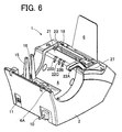
- the housing 2 is provided on the back face near the other corner with a connector part 11 (see Fig. 6) such as a USB (Universal Serial Bus) which is connected to for example a personal computer not shown.
- the roll sheet 3A is formed of a long thermal sheet (so-called "thermal paper") having a self color development property or a long label sheet formed of the thermal sheet whose one surface is bonded with a release sheet by adhesive.
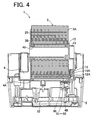
- the roll sheet 3A is in a wound state around a hollow cylindrical sheet core 3B (see Fig. 4).
- the tape printer 1 is provided with a holder support member 15 in the holder storage part 4 at a side end (a left side end in Fig. 6) in a substantially perpendicular direction to a sheet feeding direction.
- the holder support member 15 receives a mounting piece (a positioning rib) 13 of a positioning holding member (hereinafter, a "holding member”) 12 constructing the roll sheet holder 3 mentioned later.
- the mounting piece 13 is provided protruding in a substantially longitudinal rectangular shape on the outer surface of the holding member 12.
- the holder support member 15 is shaped like an angled U-shape as seen in side view of the printer 1, providing a first positioning groove 16 which opens upward in the tape printer 1 and toward both side surfaces of the holder support member 15 in a direction of the width of the tape printer.
- the holder support member 15 is also formed with a recess 15A which engages an elastic locking piece 12A formed projecting at a lower end of the holding member 12.
- the housing 2 is formed with an insertion opening 18 through which a leading end of an unwound part of the roll sheet 3A is inserted into the housing 2.
- a flat portion 21 is formed substantially horizontal between a rear end (in the feeding direction) of the slot 18 and a front upper edge portion of the holder storage part 4. On this flat portion 21, a front end portion of a guide member 20 of the roll sheet holder 3 is placed.
- the flat portion 21 is provided at a rear corner in the feeding direction with second positioning grooves (four grooves in the present embodiment) 22A to 22D each formed by a substantially L-shaped wall in section and positioned corresponding to each of a plurality of roll sheets 3A of different widths.
- Each of the second positioning grooves 22A to 22D is configured to fittingly receive a front part of the guide member 20 inserted from above, as shown in Fig. 7. Further, the front end of the guide member 20 of the roll sheet holder 3 extends to the insertion opening 18.
- a positioning recess 4A is formed in the bottom of the holder storage part 4.
- the positioning recess 4A is rectangular in plan view and long sideways in a direction substantially perpendicular to the feeding direction, extending from an inner base end of the holder support member 15 to a position corresponding to the second positioning groove 22A.
- This positioning recess 4A has a predetermined depth (about 1.5 mm to 3.0 mm in the first embodiment).
- the width of the positioning recess 4A in the feeding direction is determined to be almost equal to the width of each lower end portion of the holding member 12 and the guide member 20.
- a discrimination recess 4B is provided between the positioning recess 4A and the inner base end of the holder support member 15.
- This discrimination recess 4B is rectangular in plan view, which is long in the feeding direction, and has a depth larger by a predetermined amount (about 1.5 mm to 3.0 mm in the first embodiment) than the positioning recess 4A.
- the discrimination recess 4B will receive a sheet discrimination part 60 (see Figs. 8 to 10) mentioned later which extends inward from the lower end of the holding member 12 at a right angle therewith.
- the discrimination recess 4B there are provided five sheet discrimination sensors S1, S2, S3, S4, and S5 arranged in an L-shaped pattern for distinguishing the kind (e.g., width) of the roll sheet 3A.
- These sensors S1 to S5 are each constructed of a push type microswitch or the like, specifically, a well known mechanical switch including a plunger and a microswitch. Each plunger is placed so that an upper end thereof protrudes from the bottom surface of the discrimination recess 4B to near the bottom surface of the positioning recess 4A.
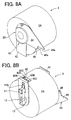
- the sheet discrimination part 60 It is detected whether the sheet discrimination part 60 has sensor holes (through holes) 60A to 60E (see Fig. 8B), mentioned later, at the positions corresponding to the sheet discrimination sensors S1 to S5 respectively. Based on an ON/OFF signal representing a detection result by the sensors S1 to S5, the kind of the roll sheet 3A held in the roll sheet holder 3 is detected.
- the tape discrimination sensors S1 to S5 are allowed to normally protrude from the bottom surface of the discrimination recess 4B to near the bottom surface of the positioning recess 4A, that is, at the height substantially corresponding to a depth difference between the discrimination recess 4B and the positioning recess 4A. At this time, each microswitch is in an OFF state.
- the plunger(s) of the sensor(s) for which the sheet discrimination part 60 has sensor hole(s) is allowed to pass through the associated sensor holes 60A to 60E without depression, leaving the corresponding microswitch(es) in the OFF state, which generates an OFF signal.
- the plunger(s) of the sensor(s) for which the sheet discrimination part 60 has no sensor hole(s) is depressed, bringing the corresponding microswitch(es) into the ON state, which generates an ON signal.
- the insertion opening 18 is arranged so that its one side end (a left end in Fig. 6) on the holder support member 15 side in the tape printer 1 is positioned substantially in one plane with the inner surface of the holder support member 15 in which the positioning groove 16 opens, more properly, in one plane with the inner surface of the positioning member 12 when engaged in the holder support member 15.
- a guide rib 23 is formed on the side end near the holder support member 15.
- a lever 27 for operating the vertical movement of a thermal head (see Fig. 7) is provided in front of the other side end (a left end in Fig. 5) of the holder storage part 4 in the feeding direction.
- the thermal head 31 is moved down and separated from a platen roller 26 (see Fig. 7).
- the thermal head 31 is moved up, thereby pressing the unwound part of the roll sheet 3A against the platen roller 26.
- a printable condition is thus developed.
- a control board 32 on which a control circuit is formed to drivingly control each mechanism in response to commands from an external personal computer and others.
- the mounting piece 13 of the positioning member 12 is inserted from above into the first positioning groove 16 of the holder support member 15.
- the elastic locking piece 12A formed projecting at the lower end of the positioning member 12 is then engaged in the locking recess 15A formed in the inner base end of the holder support member 15.
- a front lower portion (i.e., a fourth extended portion 45 mentioned later) of the guide member 20 is engaged in appropriate one of the second positioning grooves 22A to 22D and the lower end portion of the guide member 20 is fittingly inserted in the positioning recess 4A.
- the sheet discrimination part 60 extending inward from the lower end of the positioning member 12 is fitted in the discrimination recess 4B. In this state, it is detected whether or not the sheet discrimination part 60 has the sensor holes 60A to 60E corresponding to the sheet discrimination sensors S1 to S5 arranged in the discrimination recess 4B. Specifically, the kind of the roll sheet 3A held in the roll sheet holder 3 can be detected.
- a user moves the lever 27 up and inserts a leading end of a unwound part of the roll sheet 3A into the insertion opening 18 while keeping one side edge of the unwound part of the roll sheet 3A in contact with the inner surface of the guide member 20 and the other side edge in contact with the guide rib 23 provided at the side end of the insertion opening 18. Thereafter, the user moves the lever 27 down. Printing is thus enabled.
- the part of the roll sheet 3A inserted in the insertion opening 18 is pressed against the platen roller 26 by means of the thermal head 31 of a line type.
- the platen roller 26 is driven to rotate by a step motor or the like not shown while the thermal head 31 is drivingly controlled to print image data on a print surface of the roll sheet 3A which is fed sequentially.
- the printed part of the roll sheet 3A discharged onto the tray 6 is cut by a cutter unit 8 when the user moves the cut lever 9 rightward.
- the roll sheet holder 3 is constructed of the guide member 20, the holding member 12, and a holder shaft 40 of a substantially tube shape.
- the guide member 20 has a first cylindrical part 35 which is fitted in one open end of the sheet core 3B of the roll sheet 3A so that the guide member 20 is held in contact with one of the end faces of the roll sheet 3A.
- the holding member 12 has a second cylindrical part 37 which is fitted in the other open end of the sheet core 3B so that the holding member 12 is held in contact with the other end face of the roll sheet 3A.
- the holder shaft 40 has two open ends 40a and 40b; the one end 40a is fitted in the first cylindrical part 35 of the guide member 20 and formed with a radially extended flange part 36 fixed onto the outer surface of the guide member 20 and the other end 40b is fixedly fitted in the second cylindrical part 37 of the holding member 12.
- the holder shaft 40 may be selected from among a plurality of shafts of different lengths to easily provide many kinds of roll sheet holders 3 holding roll sheets 3A of different widths.
- the guide member 20 further includes a first, second, third, and fourth extended portions 41, 42, 43, and 44.
- the first extended portion 42 is formed extending downward in a predetermined length from a lower periphery of an outer end face of the first cylindrical part 35. This first extended portion 42 is fitted in the positioning recess 4A formed in the bottom of the holder storage part 4 so that the lower end surface of the first extended portion 42 is brought in contact with the bottom surface of the positioning recess 4A.
- the second extended portion 43 is formed extending upward to cover a front quarter round of the end face of the roll sheet 3A.
- the third extended portion 44 is formed continuously extending from the second extended portion 43 up to near the insertion opening 18 (see Fig. 6) and has an upper edge sloped downward to the front end.
- This third extended portion 44 further has a lower edge (44a) extending horizontally, which is held in contact with the flat portion 21 of the tape printer 1 so that one side edge of the unwound part of the roll sheet 3A is guided along the inner surfaces of the second and third extended portions 43 and 44 up to the insertion opening 18.
- the fourth extended portion 45 is formed under the third extended portion 44 between the rear end of the lower edge 44a at a predetermined distance from the front end and the first extended portion 42.
- the guide member 20 is further formed with slits 47 of a substantially rectangular shape in side view of the guide member 20, at an upper end of the first extended portion 42, i.e., at diametrical opposed positions of the periphery of the outer end face of the first cylindrical part 35.
- protrusions 48 formed on the inner surface of the flange part 36 of the holder shaft 40 are engaged for positioning.
- scales 43A, 43B, and 43C are provided in concentric circular lines on the inner surfaces of the extended portions 43, 44, and 45. These scales 43A to 43C indicate the winding lengths of the roll sheet 3A; 10 m, 20 m, and 30 m. In the present embodiment, the maximum winding length of the roll sheet 3A set in the roll sheet holder 3 is about 30 m.
- the holder shaft 40 is provided with a slit 51 in the end portion fitted in the second cylindrical part 37 of the holding member 12.
- the slit 51 has a predetermined length along the long direction of the shaft 40 to engage a rib 50 formed protruding radially inward from the inner lower end of the second cylindrical part 37.
- the first and second cylindrical parts 35 and 37 serve to rotatably support the sheet core 3B of the roll sheet 3A.
- the holder shaft 40 may be selected from among a plurality of shafts (four shafts in the first embodiment) of different lengths individually corresponding to the lengths of the sheet cores 3B (i.e., the widths of the roll sheets 3A).
- the outer open end of the second cylindrical part 37 is closed by the positioning member 12.
- a flange 55 is formed around the second cylindrical part 37.
- An extended portion 56 is continuously formed under the flange 55. Respective inner surfaces of the flange 55 and the extended portion 56 are held in contact with the end face of the roll sheet 3A and the sheet core 3B.
- the longitudinal mounting piece (positioning rib) 13 is provided protruding outward, at substantially the center of the width of the positioning member 12 in the feeding direction (a lateral direction in Fig. 10A).
- This mounting piece 13 is of a substantially rectangular section and has a vertical length in a direction substantially perpendicular to the central axis of the holder shaft 40 and a width which becomes smaller in a downward direction so that the mounting piece 13 is fitted in the first positioning groove 16 having a narrower width (in the feeding direction) towards the bottom of the holder support member 15 in the tape printer 1.
- the protruding distance of the mounting piece 13 is determined to be almost equal to the width (in a direction of the width of the tape printer 1, perpendicular to the feeding direction) of the first positioning groove 16.
- the mounting piece 13 of the positioning member 12 is provided, on the lower outer surface, with a guide portion 57 of a square flat plate (about 1.5 mm to 3.0 mm in thickness in the first embodiment) having a larger width than the lower portion of the mounting piece 13 by a predetermined amount (about 1.5 mm to 3.0 mm in the first embodiment) at each side of the lower portion. Accordingly, to mount the roll sheet holder 3 in the tape printer 1, the user inserts the mounting piece 13 from above into the first positioning groove 16 by bringing an inner surface of the guide portion 57 into sliding contact with the outer surface of the holder support member 15. Thus, the roll sheet holder 3 can easily be fitted in place.
- the positioning member 12 is designed to have the extended portion 56 extending downward longer by a predetermined length (about 1.0 mm to 2.5 mm in the first embodiment) than the lower end (the first extended portion 42) of the guide member 20.
- the positioning member 12 is also provided, at the lower end of the extended portion 56, with a sheet discrimination part 60 of a substantially rectangular shape extending inward by a predetermined length at almost right angle to the extended portion 56.
- the sheet discrimination part 60 is formed with the sensor holes 60A to 60E arranged at predetermined positions corresponding to the sheet discrimination sensors S1 to S5 respectively, in an L-shaped pattern in the present embodiment.
- the kind of roll sheet 3A held in the sheet holder 3 is represented by the number and an arrangement pattern of the sensor holes (see Fig. 13A to 13F).
- the number of the sensor holes is five at the maximum. Specifically, the presence and absence of each hole are allocated "1" and "0" respectively so that the kind of roll sheet 3A held in the roll sheet holder 3 is represented as five bits.
- the positioning member 12 is further formed with a longitudinally rectangular through hole 62 in the extended portion 56 under the mounting piece 13.
- the elastic locking piece 12A is provided extending downward from the upper edge of the through hole 62 and formed with an outward protrusion at a lower end.
- Fig. 14A shows the case where the roll sheet 3A holds a roll sheet 3A of a maximum width wound on a hollow cylindrical sheet core 3B.
- the mounting piece 13 of the holding member 12 of the holder 3 is first inserted from above into the positioning groove 16 of the holder support member 15.
- the holder 3 is put so that the lower edge 44a of the third extended portion 44 of the guide member 20 is brought into contact with the flat portion 21.
- the fourth extended portion 45 is engaged in the second positioning groove 22A formed at the rear corner of the flat portion 21 in the feeding direction.
- the first extended portion 42 of the guide member 20 is fitted in the positioning recess 4A of the holder storage part 4 so that the lower end face of the first extended portion 42 is brought into contact with the bottom surface of the positioning recess 4A.
- the sheet discrimination part 60 is fitted in the discrimination recess 4B formed at a position inwardly adjacent to the base end of the holder support member 15 and the elastic locking piece 12A is engaged in the recess 15A formed in the base end of the holder support member 15.
- the roll sheet holder 3 is mounted in the holder storage part 4 to be freely removable therefrom. Detection as to whether the sensor holes 60A to 60E of the sheet discrimination part 60 is present/absent is enabled through the sheet distinctive sensors S1 to S5 individually.
- the user turns the lever 27 upward and then draws (unwinds) part of the roll sheet 3A and inserts the leading end of the unwound part of the roll sheet 3A in the insertion opening 18 while guiding one side edge of the unwound part of the roll sheet 3A in contact with the inner surface of the guide member 20 and the other side edge in contact with the protruding guide rib 23 provided on the side end of the insertion opening 18.
- the user turns the lever 27 down.
- the inserted portion of the roll sheet 3A is thus pressed against the platen roller 26 by the thermal head 31, bringing the roll sheet 3A into a printable state.
- Fig. 14B shows the case where the roll sheet holder 3 holds a roll sheet 3A of a minimum width wound on a hollow cylindrical sheet core 3B.
- the mounting piece 13 of the holding member 12 of the holder 3 is first inserted from above into the positioning groove 16 of the holder support member 15.
- the sheet holder 3 is put so that the lower edge 44a of the third extended portion 44 of the guide member 20 is brought into contact with the flat portion 21.
- the fourth extended portion 45 is engaged in the second positioning groove 22D formed at the rear corner of the flat portion 21 in the feeding direction.
- the first extended portion 42 of the guide member 20 is fitted in the positioning recess 4A of the holder storage part 4 so that the lower end face of the first extended portion 42 is brought into contact with the bottom surface of the positioning recess 4A.
- the sheet discrimination part 60 is fitted in the discrimination recess inwardly adjacent to the base end of the holder support member 15 and the elastic locking piece 12A is engaged in the recess 15A formed in the base end of the holder support member 15.
- the roll sheet holder 3 is mounted in the holder storage part 4 to be freely removable therefrom. Detection as to whether the sensor holes 60A to 60E of the sheet discrimination part 60 is present/absent is enabled through the sheet distinctive sensors S1 to S5 individually.
- the user turns the lever 27 up and then draws (unwinds) part of the roll sheet 3A to insert the leading end of the unwound part of the roll sheet 3A in the insertion opening 18 while guiding one side edge of the unwound part of the roll sheet 3A in contact with the inner surface of the guide member 20 and the other side edge in contact with the protruding guide rib 23 provided on the side end of the insertion opening 18.
- the user turns the lever 27 down.
- the inserted portion of the roll sheet 3A is thus pressed against the platen roller 26 by the thermal head 31, bringing the roll sheet 3A into a printable state.
- the above components in the present embodiment correspond to each element of the invention as below.
- the platen roller 26 serves as a feeding device.
- the platen roller 26 and the thermal head 31 in combination construct a printing device.
- the first, second, third, and fourth extended portions 42, 43, 44, and 45 construct a first flange part.
- the second cylindrical part 37 serves as a second cylindrical part.
- the positioning holding member 12 serves as a positioning holding member whereby the roll sheet holder 3 is positioned in place in the tape printer 1.
- the flange part 36 serves as a second flange part.
- the mounting piece 13 serves as a positioning rib.
- the sensor holes 60A-60E construct a roll sheet identifying part.
- the holder support member 15 and the locking recess 15A construct a support mechanism. Further, the holder support member 15 serves as a positioning support member.
- the discrimination recess 4B serves as a recess.
- the sheet discrimination sensors S1 to S5 are provided near the base end of the holder support member 15 and serve in cooperation with the sensor holes 60A to 60E of the sheet discrimination part 60 to identify the kind of the roll sheet 3A.
- the sensor holes 60A to 60E of the sheet discrimination part 60 can be positioned in place. The detection precision of each sensor S1 to S5 can be enhanced.
- the discrimination recess 4B is formed in the inside bottom of the holder storage part 4 as mentioned above.
- the holder 3 is put from above into the holder storage part 4 and also the sheet discrimination part 60 is fitted from above in the discrimination recess 4B.
- the sensor holes 60A to 60E can easily be positioned in place. This makes it possible to surely enable operation of each sheet discrimination sensor S1 to S5, thereby improving the reliability of the sensors S1 to S5.
- the mounting piece 13 provided protruding from the outer surface of the holding member 12 of the roll sheet holder 3 is positioned and slid into the first positioning groove 16 which opens upward in the tape printer 1. Then, the kind of the roll sheet 3A is specified by means of the sensor holes 60A to 60E of the sheet discrimination part 60 having a predetermined length extending from the lower end of the holding member 12 to face the lower portion of the outer peripheral surface of the roll sheet 3A of the maximum diameter.
- the sheet discrimination part 60 with the sensor holes 60A to 60E can be placed vertically below the central axis of the roll sheet 3A. Accordingly, the sheet holder 3 can be held down by the own weight of the roll sheet 3A to fixedly dispose the sheet discrimination part 60 in place with respect to the sheet discrimination sensors S1 to S5, thereby preventing the sheet discrimination part 60 from coming off upward.
- the sheet discrimination part 60 is provided extending by a predetermined length from the lower end of the positioning member 12 to face the lower portion of the outer peripheral surface of the roll sheet 3A of the maximum diameter. Accordingly, even when a winding state of the roll sheet 3A slightly loosens due to an elastic restoring force of the roll sheet 3A, the lower portion of the outer peripheral surface of the roll sheet 3A is pressed against the sheet discrimination part 60. This makes it possible to surely prevent the roll sheet 3A from further loosening.
- the sheet discrimination part 60 with the sensor holes 60A to 60E is held in place by the sensors S1 to S5 passing through the corresponding sensor holes 60A to 60E. It is therefore possible to prevent the sensor holes 60A to 60E from coming off the corresponding sensors S1 to S5 and to provide an improvement in print quality.
- the schematic structures of the roll sheet holder and the tape printer in the second embodiment are substantially the same as those of the roll sheet holder 3 and the tape printer 1 in the first embodiment.
- various kinds of processing for controlling the tape printer are substantially the same as those in the first embodiment.
- a different structure from the first embodiment is in that a positioning holding member of the roll sheet holder and a discrimination recess formed in a roll sheet holder storage part of the tape printer in the second embodiment differ from the holding member 12 of the roll sheet holder 3 and the discrimination recess 4B formed in the holder storage part 4 of the tape printer 1 in the first embodiment.
- a recess 4A is formed in a bottom of a roll sheet holder storage part 4 in a tape printer 71 in the second embodiment.
- the recess 4A is rectangular in plan view and long sideways in a direction substantially perpendicular to the feeding direction, extending from an inner base end of the holder support member 15 to a position corresponding to the second positioning groove 22A.
- This recess 4A has a predetermined depth (about 1.5 mm to 3.0 mm in the second embodiment).
- the width of the positioning recess 4A in the feeding direction is determined to be almost equal to the width of each lower end portion of a positioning holding member (hereinafter, a "holding member") 72 (see Fig. 16) of the roll sheet holder 3 and the guide member 20.
- a discrimination recess 75 is provided between the positioning recess 4A and the inner base end of the holder support member 15.
- This discrimination recess 75 is rectangular in plan view, which is long in the feeding direction, and has a depth larger by a predetermined distance (about 1.5 mm to 3.0 mm in the second embodiment) than the positioning recess 4A.
- the discrimination recess 75 will receive a sheet discrimination part 73 (see Fig. 16) mentioned later which extends inward from the lower end of the holding member 72 at a right angle thereto.
- the discrimination recess 75 is shaped to be smaller in width in a front part (a lower part in Fig. 15) in the feeding direction from substantially the center between sheet discrimination sensors S3 and S4 so that the boundary between the discrimination recess 75 and the positioning recess 4A is substantially aligned with sheet discrimination sensor S1, that is, the positioning recess 4A is partially extended inside the discrimination recess 75 (rightward in Fig. 15).
- this discrimination recess 75 there are provided five sheet discrimination sensors S1, S2, S3, S4, and S5 arranged in an L-shaped pattern for distinguishing the kind of the roll sheet 3A.
- These sensors S1 to S5 are each constructed of a push type microswitch or the like, specifically, a well known mechanical switch including a plunger and a microswitch. Each plunger is placed so that an upper end thereof protrude from the bottom surface of the discrimination recess 75 to near the bottom surface of the positioning recess 4A.
- the sheet discrimination part 73 has sensor holes 73A to 73E (see Fig. 16), mentioned later, at the positions corresponding to the sheet discrimination sensors S1 to S5 respectively. Based on an ON/OFF signal representing a detection result through the sensors S1 to S5, the kind of the roll sheet 3A held in the roll sheet holder 3 is detected.
- the tape discrimination sensors S1 to S5 are allowed to normally protrude from the bottom surface of the discrimination recess 75 to near the bottom surface of the positioning recess 4A, that is, at the height corresponding to a depth difference between the discrimination recess 75 and the positioning recess 4A. At this time, each microswitch is in an OFF state.
- the sheet discrimination part 73 has the sensor holes 73A to 73E at the corresponding positions to the sheet discrimination sensors S1 to S5
- respective plungers are allowed to pass through the corresponding sensor holes 73A to 73E without depression and respective microswitches are in the OFF state, each generating an OFF signal.
- the sheet discrimination part 73 have only one or some of the sensor holes 73A to 73E at the corresponding positions to the sheet discrimination sensors S1 to S5
- the plunger(s) of the relevant sensor(s) for which the sheet discrimination part 60 has no sensor hole(s) is depressed, bringing the corresponding microswitch(es) into the ON state, which generates an ON signal.
- the holding member 72 of the roll sheet holder 3 in the second embodiment has substantially the same structure as the holding member 12 in the first embodiment expect that the extended portion 56 of the holding member 72 is formed at a lower end with the sheet discrimination part 73 different from the sheet discrimination part 60.
- This sheet discrimination part 73 of the holding member 72 extends inward by a predetermined length from the lower end of the extended portion 56 and at almost right angle to the extended portion 56.
- the sheet discrimination part 73 has an extended portion of a predetermined length at a rear end in the feeding direction so that the sheet discrimination part 73 is of an almost L-shape in plan view.
- the sensor holes 73A and 73B are formed in line in the extended portion of the sheet discrimination part 73, i.e., in the rear end portion in the feeding direction, and the sensor holes 73B to 73E are formed in line along the feeding direction so that the sensor holes 73A to 73E are arranged at predetermined positions corresponding to the sheet discrimination sensors S1 to S5 respectively, showing an L-shaped pattern.
- the number of the sensor holes is five at the maximum. Specifically, the presence and absence of each hole are allocated "1" and "0" respectively so that the kind of the roll sheet 3A held in the roll sheet holder 3 be represented as five bits.
- the sensor holes 73A to 73E construct a roll sheet identifying part.
- the holding member 72 serves as a positioning holding member.
- the discrimination recess 75 serves as a recess.
- the tape printer 71 in the second embodiment can provide the same effects as the tape printer 1 in the first embodiment and further can achieve a reduction in size of the sheet discrimination part 73 of the holding member 72, which results in reductions in materials of the roll sheet holder 3 and manufacturing cost.
- a third preferred embodiment of the roll sheet holder and the tape printer will be explained below with reference to Figs. 17 and 18. Similar or identical elements of the roll sheet holder and the tape printer in the third embodiment to those in the first embodiment are indicated by the same reference numbers.
- the schematic structures of the roll sheet holder and the tape printer in the third embodiment are substantially the same as those of the roll sheet holder 3 and the tape printer 1 in the first embodiment.
- various kinds of processing for controlling the tape printer are substantially the same as those in the first embodiment.
- a different structure from the first embodiment is in that a positioning holding member of the roll sheet holder and a discrimination recess formed in a roll sheet holder storage part of the tape printer in the third embodiment differ from the holding member 12 of the roll sheet holder 3 and the discrimination recess 4B formed in the holder storage part 4 of the tape printer 1 in the first embodiment.
- a recess 4A is formed in a bottom of a roll sheet holder storage part 4 in a tape printer 81 in the third embodiment.
- the recess 4A is rectangular in plane view and long sideways in a direction substantially perpendicular to the feeding direction, extending from an inner base end of the holder support member 15 to a position corresponding to the second positioning groove 22.
- This recess 4A has a predetermined depth (about 1.5 mm to 3.0 mm in the third embodiment).
- the width of the positioning recess 4A in the feeding direction is determined to be almost equal to the width of each lower end portion of a positioning holding member (hereinafter, a "holding member") 82 (see Fig. 18) of the roll sheet holder 3 and the guide member 20.
- a discrimination recess 85 is provided between the positioning recess 4A and the inner base end of the holder support member 15.
- This discrimination recess 85 is substantially rectangular in plan view, which is long in the feeding direction, and has a depth larger by a predetermined distance (about 1.5 mm to 3.0 mm in the third embodiment) than the positioning recess 4A.
- the discrimination recess 85 will receive a sheet discrimination part 83 (see Fig. 18) mentioned later which extends inward from the lower end of the holding member 82 at a right angle thereto.
- the discrimination recess 85 is shaped to be smaller in width in substantially a center part in the feeding direction, corresponding to between the sheet discrimination sensors S3 and S4, so that the boundary between the discrimination recess 85 and the positioning recess 4A is substantially aligned with the sensor S1, that is, the positioning recess 4A is partially extended inside the discrimination recess 85 (rightward in Fig. 17), forming a positioning projection 86 whose edge is aligned with the sensor S1.
- this discrimination recess 85 there are five sheet discrimination sensors S1, S2, S3, S4, and S5 arranged in an L-shaped pattern for distinguishing the kind of the roll sheet 3A.
- These sensors S1 to S5 are each constructed of a push type microswitch or the like, specifically, a well known mechanical switch including a plunger and a microswitch. Each plunger is placed so that an upper end thereof protrude from the bottom surface of the discrimination recess 85 to near the bottom surface of the positioning recess 4A.
- the sheet discrimination part 83 It is detected whether the sheet discrimination part 83 has sensor holes 83A to 83E (see Fig. 18), mentioned later, at the positions corresponding to the sheet discrimination sensors S1 to S5 respectively. Based on an ON/OFF signal representing a detection result through the sensors S1 to S5, the kind of the roll sheet 3A held in the roll sheet holder 3 is detected.
- the tape discrimination sensors S1 to S5 are allowed to normally protrude from the bottom surface of the discrimination recess 85 to near the bottom surface of the positioning recess 4A, that is, at the height corresponding to a depth difference between the discrimination recess 85 and the positioning recess 4A. At this time, each microswitch is in an OFF state.
- the sheet discrimination part 60 has the sensor holes 83A to 83E at the positions corresponding to the sheet discrimination sensors S1 to S5, respective plungers are allowed to pass through the corresponding sensor holes 83A to 83E without depression and respective microswitches are in the OFF state, each generating an OFF signal.
- the sheet discrimination part 83 have only one or some of the sensor holes 83A to 83E at the positions corresponding to the sheet discrimination sensors S1 to S5, the plunger(s) of the sensor(s) for which the sheet discrimination part 83 has no sensor hole(s) is depressed, bringing the corresponding microswitch(es) into the ON state, which generates an ON signal.
- the holding member 82 of the roll sheet holder 3 in the third embodiment has substantially the same structure as the holding member 12 in the first embodiment except that the extended portion 56 of the holding member 82 is formed at a lower end with the sheet discrimination part 83 different from the sheet discrimination part 60.
- This sheet discrimination part 83 of the holding member 82 extends inward by a predetermined length from the lower end of the extended portion 56 and at almost right angle to the extended portion 56.
- the sheet discrimination part 83 is shaped to have a cut-out (rightward in Fig.
- a positioning recess 87 having a length corresponding to between the sensor holes 83C and 83D and a width so that the edge of the positioning recess 87 is substantially aligned with the sensor hole 83A.
- the sensor holes 83A and 83B are formed in line in the rear end portion of the sheet discrimination part 83 in the feeding direction and the sensor holes 83B to 83E are formed in line along the feeding direction so that the sensor holes 83A to 83E are arranged at predetermined positions corresponding to the sheet discrimination sensors S1 to S5 respectively, showing an L-shaped pattern.
- the number of the sensor holes is five at the maximum. Specifically, the presence and absence of each hole are allocated "1" and "0" respectively so that the kind of the roll sheet 3A held in the roll sheet holder 3 be represented as five bits.
- the sensor holes 83A to 83E construct a roll sheet identifying part.
- the holding member 82 serves as a positioning holding member.
- the discrimination recess 85 serves as a recess.
- the tape printer 81 in the third embodiment can provide the same effects as the tape printer 1 in the first embodiment. Since the positioning recess 87 of the sheet discrimination part 83 is engaged with the positioning projection 86 of the positioning recess 4A extended toward the holder support member 15, the holding member 82 can be prevented from wobbling at the lower end when the roll sheet holder 3 is set in the tape printer 1.
- the tape printer 1 in the present embodiment can provide an improved printing quality.
- the present invention is not limited to the above mentioned first through third embodiments and may be embodied in other specific forms without departing from the essential characteristics thereof. For example, the following embodiments may be adopted.
- the holding members 12, 72, and 82 each constructing the roll sheet holder 3 are provided with the sheet discrimination parts 60, 73, and 83 which extend inward and have the sensor holes 60A-60E, 73A-73E, and 83A-83E respectively which the sheet discrimination sensors S1-S5 are passed through.
- the sheet discrimination parts 60, 73, and 83 may be provided, on the undersurface, with projections whereby the sensors S1-S5 are depressed according to the arrangement of the projections.
- a positioning holding member 91 is provided with a sheet discrimination part 92 having a similar shape to the above mentioned sheet discrimination part 60.
- the sheet discrimination part 92 is of a substantially rectangular shape extending inward by a predetermined length from a portion slightly above the lower end of an extended portion 56 of the holding member 91 at a predetermined height corresponding to the bottom surface of the positioning recess 4A.
- the sheet discrimination part 92 is formed, on the undersurface, with push bosses 92A to 92E protruding at the positions corresponding to the sheet discrimination sensors S1 to S5. It is to be noted that only a push boss 92E is provided in Figs. 19A and 19B. These bosses 92A to 92E are formed to have a height (length) so that each lower surface be flush with the lower end surface of the extended portion 56.
- the sheet discrimination part 92 is provided with all of the push bosses 92A to 92E on the undersurface, it corresponds to each of the sheet discrimination parts 60, 73, and 83 that do not have any sensor holes 60A-60E, 73A-73E, and 83A-83E respectively. If the sheet discrimination part 92 is provided with only the push boss 92E as shown in Figs. 19A and 19B, it corresponds to the sheet discrimination parts 60, 73, and 83 each having four sensor holes 60A-60D, 73A-73D, and 83A-83D respectively.
- the sheet discrimination part 92 is not provided with any push bosses 92A-92E, it corresponds to the sheet discrimination parts 60, 73, and 83 each having five sensor holes 60A-60E, 73A-73E, and 83A-83E respectively.
- Each roll sheet holder 3 in the first, second, third, and fourth embodiments holds the roll sheet 3A would on the sheet core 3B.
- the roll sheet 3A may be rolled up by itself without the sheet core 3B as shown in Figs. 20 and 21 so that a cylindrical through hole 3D is centrally formed having an inner diameter substantially equal to the outer diameters of the second cylindrical part 37 of the holding member 12 and the first cylindrical part 35 of the guide member 20.
Abstract
Description
- The present invention relates to a roll sheet holder which rotatably holds a roll sheet wound on a cylindrical sheet core and is removably mounted in a tape printer provided with a feeding device for feeding the roll sheet and a printing unit for printing on the roll sheet. Further, the present invention relates to a tape printer in which the roll sheet holder is removably mounted.
- Heretofore, various types of tape printers have been proposed to print characters and others on a long sheet formed of a self-adhesive sheet applied with a release sheet by means of a thermal head. Some tape printers of this type are provided with a roll sheet wound on a sheet core, a roll sheet holder which rotatably holds therein the sheet core, a support mechanism which removably mounts the roll sheet holder in the tape printer, and a feeding device for feeding part of the roll sheet while drawing the roll sheet from the roll sheet holder. The roll sheet holder may be selected from among plural holders of different sizes individually corresponding to various sheet widths.
- One of the roll sheet holders mounted in the tape printer is disclosed in
Japanese utility model unexamined publication No. H3-19047 (1997 19407 - For image recording, the tape printer using the recording sheet holding case constructed as above can distinguish the kind of thermal recording sheet stored in the sheet holding case by means of a microswitch or the like provided in the bottom of the sheet holding case and thereby control the application of electric power to a thermal head. Accordingly, images can be printed at an appropriate color density on the thermal recording sheet mounted in the printer.
- However, the conventional tape printer in which the above mentioned recording sheet holding case is mounted has the following disadvantages. When part of the thermal recording sheet is unwound, the holding case is caused to rotate in a direction of drawing of the sheet. Accordingly, lower end faces of the projections of the holding case whereby the microswitch is pressed down are moved up to come off the microswitch. This may cause a problem that images are printed at an inappropriate color density on the thermal recording sheet.
- The present invention has been made in view of the above circumstances and has an object to overcome the above problems and to provide a roll sheet holder which can be prevented from rotating in a direction of drawing a roll sheet from the holder to hold a bottom of the roll sheet holder against upward dislocation.
- Additional objects and advantages of the invention will be set forth in part in the description which follows and in part will be obvious from the description, or may be learned by practice of the invention. The objects and advantages of the invention may be realized and attained by means of the instrumentalities and combinations particularly pointed out in the appended claims.
- To achieve the purpose of the invention, there is provided a roll sheet holder which holds a roll sheet wound on a cylindrical sheet core having a through hole opening at both ends and is removably mountable in a tape printer which includes a feeding device which draws the roll sheet to feed an unwound part thereof, a printing device which prints on the part of the roll sheet fed by the feeding device, wherein the roll sheet holder comprises: a guide member including a first flange part arranged in contact with one end face of the roll sheet; and a positioning holding member arranged in contact with the other end face of the roll sheet; the roll sheet holder is mountable in the tape printer which includes an insertion opening in which the unwound part of the roll sheet is inserted and a support portion provided upstream of the insertion opening in a direction of feeding the unwound part of the roll sheet; the first flange part includes: a first extended portion extending downward in a predetermined length, which is brought into contact with a bottom surface of the tape printer when the roll sheet holder is mounted therein; and a frontward extended portion extending frontward to outside of an outermost surface of the roll sheet of a maximum diameter, the frontward extended portion having a lower edge which is brought into contact with an upper surface of the support portion when the roll sheet holder is mounted in the tape printer; and the roll sheet holder is arranged such that the roll sheet is unwound from above the sheet core and inserted in the insertion opening when the roll sheet holder is mounted in the tape printer.
- According to the above roll sheet holder, one end of the sheet core on which the roll sheet is wound is fixed to the first flange part so that one end face of the roll sheet is held in contact with the first flange part. When the roll sheet holder is mounted in the tape printer, the lower edge of the frontward extended portion of the first flange part is brought into contact with the upper surface of the support portion provided upstream of the insertion opening in which the unwound part of the roll sheet is to be inserted. Then, the roll sheet is drawn from above the sheet core and inserted in the insertion opening. With the frontward extended portion whose lower edge is in contact with the upper surface of the support portion, the roll sheet holder can be prevented from rotating in a direction of drawing the roll sheet when the roll sheet is drawn. This makes it possible to reliably hold the bottom of the roll sheet holder against upward dislocation.
- According to another aspect, the invention provides a tape printer including a roll sheet wound on a cylindrical sheet core having a through hole opening at both ends, a feeding device which draws the roll sheet to feed an unwound part thereof, and a printing device which prints on the part of the roll sheet fed by the feeding device, the tape printer comprising: a roll sheet holder which holds the roll sheet wound on the sheet core, the roll sheet holder including: a guide member including a first flange part arranged in contact with one end face of the roll sheet; a positioning holding member arranged in contact with the other end face of the roll sheet; the first flange part including: first extended portion extending downward in a predetermined length, which is brought into contact with a bottom surface of the tape printer when the roll sheet holder is mounted therein; and a frontward extended portion extending frontward to outside of an outermost surface of the roll sheet of a maximum diameter; an insertion opening in which the unwound part of the roll sheet is inserted; and a support mechanism which removably supports the roll sheet holder in the tape printer, the support mechanism including: a support portion which is provided upstream of the insertion opening in a direction of feeding the unwound part of the roll sheet and has an upper surface with which a lower edge of the frontward extended portion of the guide member of the roll sheet holder is brought into contact when the roll sheet holder is mounted in the tape printer; wherein the roll sheet holder is arranged such that the roll sheet is unwound from above the sheet core and inserted in the insertion opening when the roll sheet holder is mounted in the tape printer.
- In the above tape printer, the support mechanism which removably supports the roll sheet holder within the tape printer is provided with the support portion at a position upstream of the insertion opening in the feeding direction. In the roll sheet holder, one end of the sheet core on which the roll sheet is wound is fixed to the first flange part so that one end face of the roll sheet is held in contact with the first flange part. When the roll sheet holder is mounted in the tape printer, the lower edge of the frontward extended portion of the first flange part is brought into contact with the upper surface of the support portion and the roll sheet is drawn from above the sheet core and inserted in the insertion opening. With the frontward extended portion whose lower edge is in contact with the upper surface of the support portion, the roll sheet holder can be prevented from rotating in a direction of drawing the roll sheet when the roll sheet is drawn therefrom. This makes it possible to reliably hold the bottom of the roll sheet holder against upward dislocation.
- Further developments of the present invention are given in the dependent claims.
- The accompanying drawings, which are incorporated in and constitute a part of this specification illustrate an embodiment of the invention and, together with the description, serve to explain the objects, advantages and principles of the invention.
- In the drawings,
- Fig. 1 is a schematic perspective view of a tape printer in a first embodiment;
- Fig. 2 is a perspective view of the tape printer of which a top cover is removed, in which a roll sheet holder holding a roll sheet of a maximum width is mounted;
- Fig. 3 is a side view of the tape printer of Fig. 2;
- Fig. 4 is a sectional view taken along a line X-X in Fig. 3;
- Fig. 5A is a schematic perspective view of the tape printer in the first embodiment, from which the top cover is removed;
- Fig. 5B is an enlarged perspective view of a portion indicated by a dashed circle W in Fig. 5A;
- Fig. 6 is a schematic perspective back view of the tape printer in the first embodiment, from which the top cover is removed;
- Fig. 7 is a sectional side view of the tape printer in the first embodiment, from which the top cover is removed;
- Fig. 8A is a perspective view of a roll sheet holder holding a roll sheet, seen from an obliquely front direction;
- Fig. 8B is a perspective view of the roll sheet holder turned upside down, seen from an obliquely front direction;
- Fig. 9A is a perspective view of the roll sheet holder alone seen from an obliquely back direction;
- Fig. 9B is a perspective view of the roll sheet holder alone seen from an obliquely front direction;
- Fig. 10A is a side view of the roll sheet holder in the first embodiment, seen from left of the roll sheet holder in Fig. 10B;
- Fig. 10B is a back view of the roll sheet holder in the first embodiment;
- Fig. 10C is a side view of the roll sheet holder in the first embodiment, seen from right of the roll sheet holder in Fig. 10B;
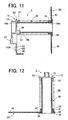
- Fig. 11 is a sectional view of the roll sheet holder taken along a line Y-Y in Fig. 10A;
- Fig. 12 is a sectional view of the roll sheet holder taken along a line Z-Z in Fig. 10A;
- Figs. 13A to 13F are partial views showing arrangement examples of sensor holes indicating the kinds of roll sheets, the holes being provided in a sheet discrimination part of a positioning holding member constructing a roll sheet holder in the first embodiment;
- Fig. 14A is a perspective view of the tape printer in the first embodiment, in which the roll sheet holder for a maximum roll sheet width is mounted;
- Fig. 14B is a perspective view of the tape printer in the first embodiment, in which the roll sheet holder for a minimum roll sheet width is mounted;
- Fig. 15 is an enlarged perspective view of a tape printer in a second embodiment, showing a discrimination recess of a roll sheet holder storage part;
- Fig. 16 is a perspective view of one example of a positioning holding member constructing the roll sheet holder in the second embodiment;
- Fig. 17 is an enlarged perspective view of a tape printer in a third embodiment, showing a discrimination recess of a roll sheet holder storage part;
- Fig. 18 is a perspective view of one example of a positioning holding member constructing the roll sheet holder in the third embodiment;
- Fig. 19A is a perspective inside view of one example of a positioning holding member constructing a roll sheet holder in another embodiment;
- Fig. 19B is a perspective outside view of the positioning holding member placed upside down of Fig. 19A; and
- Fig. 20 is a schematic sectional view of the roll sheet holder of the tape printer in the first embodiment, taken along a line Y-Y in Fig. 10A, in which another roll sheet in a rolled state is set; and
- Fig. 21 is a schematic sectional view of the roll sheet holder of the tape printer in the first embodiment, taken along a line Z-Z in Fig. 10A, in which another roll sheet in a rolled state is set.
- A detailed description of preferred embodiments of a roll sheet holder and a tape printer embodying the present invention will now be given referring to the accompanying drawings.
- A first embodiment of the tape printer is first explained below with reference to Figs. 1 through 7.
- As shown in Figs. 1 to 3, the
tape printer 1 includes ahousing 2, atop cover 5 made of transparent resin attached to thehousing 2 at a rear upper edge, atray 6 made of transparent resin set in a vertical position to face a substantially front center of thetop cover 5, apower button 7 placed in front of thetray 6, acutter lever 9 provided in a front face of thehousing 2, and others. Thetop cover 5 is freely opened and closed, thereby covering an upper part of a roll sheet holder storage part (hereinafter, a "holder storage part") 4 which is a space for receiving aroll sheet holder 3 holding aroll sheet 3A of a predetermined width (see Fig.14). Thecutter lever 9 is movable side to side to horizontally move a cutter unit 8 (see Fig. 7). Apower cord 10 is connected to thehousing 2 on a back face near a corner. Thehousing 2 is provided on the back face near the other corner with a connector part 11 (see Fig. 6) such as a USB (Universal Serial Bus) which is connected to for example a personal computer not shown. Theroll sheet 3A is formed of a long thermal sheet (so-called "thermal paper") having a self color development property or a long label sheet formed of the thermal sheet whose one surface is bonded with a release sheet by adhesive. Theroll sheet 3A is in a wound state around a hollowcylindrical sheet core 3B (see Fig. 4). - As shown in Figs. 2 through 6, the
tape printer 1 is provided with aholder support member 15 in theholder storage part 4 at a side end (a left side end in Fig. 6) in a substantially perpendicular direction to a sheet feeding direction. Theholder support member 15 receives a mounting piece (a positioning rib) 13 of a positioning holding member (hereinafter, a "holding member") 12 constructing theroll sheet holder 3 mentioned later. The mountingpiece 13 is provided protruding in a substantially longitudinal rectangular shape on the outer surface of the holdingmember 12. Specifically, theholder support member 15 is shaped like an angled U-shape as seen in side view of theprinter 1, providing afirst positioning groove 16 which opens upward in thetape printer 1 and toward both side surfaces of theholder support member 15 in a direction of the width of the tape printer. Theholder support member 15 is also formed with arecess 15A which engages anelastic locking piece 12A formed projecting at a lower end of the holdingmember 12. - The
housing 2 is formed with aninsertion opening 18 through which a leading end of an unwound part of theroll sheet 3A is inserted into thehousing 2. Aflat portion 21 is formed substantially horizontal between a rear end (in the feeding direction) of theslot 18 and a front upper edge portion of theholder storage part 4. On thisflat portion 21, a front end portion of aguide member 20 of theroll sheet holder 3 is placed. Theflat portion 21 is provided at a rear corner in the feeding direction with second positioning grooves (four grooves in the present embodiment) 22A to 22D each formed by a substantially L-shaped wall in section and positioned corresponding to each of a plurality ofroll sheets 3A of different widths. Each of thesecond positioning grooves 22A to 22D is configured to fittingly receive a front part of theguide member 20 inserted from above, as shown in Fig. 7. Further, the front end of theguide member 20 of theroll sheet holder 3 extends to theinsertion opening 18. - A
positioning recess 4A is formed in the bottom of theholder storage part 4. Thepositioning recess 4A is rectangular in plan view and long sideways in a direction substantially perpendicular to the feeding direction, extending from an inner base end of theholder support member 15 to a position corresponding to thesecond positioning groove 22A. Thispositioning recess 4A has a predetermined depth (about 1.5 mm to 3.0 mm in the first embodiment). The width of thepositioning recess 4A in the feeding direction is determined to be almost equal to the width of each lower end portion of the holdingmember 12 and theguide member 20. Adiscrimination recess 4B is provided between thepositioning recess 4A and the inner base end of theholder support member 15. Thisdiscrimination recess 4B is rectangular in plan view, which is long in the feeding direction, and has a depth larger by a predetermined amount (about 1.5 mm to 3.0 mm in the first embodiment) than thepositioning recess 4A. Thediscrimination recess 4B will receive a sheet discrimination part 60 (see Figs. 8 to 10) mentioned later which extends inward from the lower end of the holdingmember 12 at a right angle therewith. - In the
discrimination recess 4B, there are provided five sheet discrimination sensors S1, S2, S3, S4, and S5 arranged in an L-shaped pattern for distinguishing the kind (e.g., width) of theroll sheet 3A. These sensors S1 to S5 are each constructed of a push type microswitch or the like, specifically, a well known mechanical switch including a plunger and a microswitch. Each plunger is placed so that an upper end thereof protrudes from the bottom surface of thediscrimination recess 4B to near the bottom surface of thepositioning recess 4A. - It is detected whether the
sheet discrimination part 60 has sensor holes (through holes) 60A to 60E (see Fig. 8B), mentioned later, at the positions corresponding to the sheet discrimination sensors S1 to S5 respectively. Based on an ON/OFF signal representing a detection result by the sensors S1 to S5, the kind of theroll sheet 3A held in theroll sheet holder 3 is detected. In the first embodiment, the tape discrimination sensors S1 to S5 are allowed to normally protrude from the bottom surface of thediscrimination recess 4B to near the bottom surface of thepositioning recess 4A, that is, at the height substantially corresponding to a depth difference between thediscrimination recess 4B and thepositioning recess 4A. At this time, each microswitch is in an OFF state. - In the case where the
sheet discrimination part 60 has some sensor hole(s) 60A to 60E at the positions corresponding to the sheet discrimination sensors S1 to S5, the plunger(s) of the sensor(s) for which thesheet discrimination part 60 has sensor hole(s) is allowed to pass through the associatedsensor holes 60A to 60E without depression, leaving the corresponding microswitch(es) in the OFF state, which generates an OFF signal. - On the other hand, the plunger(s) of the sensor(s) for which the
sheet discrimination part 60 has no sensor hole(s) is depressed, bringing the corresponding microswitch(es) into the ON state, which generates an ON signal. - The
insertion opening 18 is arranged so that its one side end (a left end in Fig. 6) on theholder support member 15 side in thetape printer 1 is positioned substantially in one plane with the inner surface of theholder support member 15 in which thepositioning groove 16 opens, more properly, in one plane with the inner surface of the positioningmember 12 when engaged in theholder support member 15. In theinsertion opening 18, aguide rib 23 is formed on the side end near theholder support member 15. - A
lever 27 for operating the vertical movement of a thermal head (see Fig. 7) is provided in front of the other side end (a left end in Fig. 5) of theholder storage part 4 in the feeding direction. To be more specific, when thelever 27 is turned up, thethermal head 31 is moved down and separated from a platen roller 26 (see Fig. 7). When thelever 27 is turned down, to the contrary, thethermal head 31 is moved up, thereby pressing the unwound part of theroll sheet 3A against theplaten roller 26. A printable condition is thus developed. Further, below theroll sheet holder 4, there is provided acontrol board 32 on which a control circuit is formed to drivingly control each mechanism in response to commands from an external personal computer and others. - The
roll sheet holder 3 in which theroll sheet 3A wound on thesheet core 3B is removably set in theholder storage part 4 in the following manner. The mountingpiece 13 of the positioningmember 12 is inserted from above into thefirst positioning groove 16 of theholder support member 15. Theelastic locking piece 12A formed projecting at the lower end of the positioningmember 12 is then engaged in thelocking recess 15A formed in the inner base end of theholder support member 15. A front lower portion (i.e., a fourthextended portion 45 mentioned later) of theguide member 20 is engaged in appropriate one of thesecond positioning grooves 22A to 22D and the lower end portion of theguide member 20 is fittingly inserted in thepositioning recess 4A. Thesheet discrimination part 60 extending inward from the lower end of the positioningmember 12 is fitted in thediscrimination recess 4B. In this state, it is detected whether or not thesheet discrimination part 60 has the sensor holes 60A to 60E corresponding to the sheet discrimination sensors S1 to S5 arranged in thediscrimination recess 4B. Specifically, the kind of theroll sheet 3A held in theroll sheet holder 3 can be detected. - A user (operator) moves the
lever 27 up and inserts a leading end of a unwound part of theroll sheet 3A into theinsertion opening 18 while keeping one side edge of the unwound part of theroll sheet 3A in contact with the inner surface of theguide member 20 and the other side edge in contact with theguide rib 23 provided at the side end of theinsertion opening 18. Thereafter, the user moves thelever 27 down. Printing is thus enabled. - As shown in Fig. 7, when the
lever 27 is moved down, the part of theroll sheet 3A inserted in theinsertion opening 18 is pressed against theplaten roller 26 by means of thethermal head 31 of a line type. Theplaten roller 26 is driven to rotate by a step motor or the like not shown while thethermal head 31 is drivingly controlled to print image data on a print surface of theroll sheet 3A which is fed sequentially. The printed part of theroll sheet 3A discharged onto thetray 6 is cut by acutter unit 8 when the user moves thecut lever 9 rightward. - A schematic structure of the
roll sheet holder 3 is explained below with reference to Figs. 8 through 13. - As shown in Fig. 8 through 13, the
roll sheet holder 3 is constructed of theguide member 20, the holdingmember 12, and aholder shaft 40 of a substantially tube shape. Theguide member 20 has a firstcylindrical part 35 which is fitted in one open end of thesheet core 3B of theroll sheet 3A so that theguide member 20 is held in contact with one of the end faces of theroll sheet 3A. The holdingmember 12 has a secondcylindrical part 37 which is fitted in the other open end of thesheet core 3B so that the holdingmember 12 is held in contact with the other end face of theroll sheet 3A. Theholder shaft 40 has twoopen ends end 40a is fitted in the firstcylindrical part 35 of theguide member 20 and formed with a radially extendedflange part 36 fixed onto the outer surface of theguide member 20 and theother end 40b is fixedly fitted in the secondcylindrical part 37 of the holdingmember 12. Theholder shaft 40 may be selected from among a plurality of shafts of different lengths to easily provide many kinds ofroll sheet holders 3 holdingroll sheets 3A of different widths. - The
guide member 20 further includes a first, second, third, and fourthextended portions extended portion 42 is formed extending downward in a predetermined length from a lower periphery of an outer end face of the firstcylindrical part 35. This firstextended portion 42 is fitted in thepositioning recess 4A formed in the bottom of theholder storage part 4 so that the lower end surface of the firstextended portion 42 is brought in contact with the bottom surface of thepositioning recess 4A. The secondextended portion 43 is formed extending upward to cover a front quarter round of the end face of theroll sheet 3A. The thirdextended portion 44 is formed continuously extending from the secondextended portion 43 up to near the insertion opening 18 (see Fig. 6) and has an upper edge sloped downward to the front end. This thirdextended portion 44 further has a lower edge (44a) extending horizontally, which is held in contact with theflat portion 21 of thetape printer 1 so that one side edge of the unwound part of theroll sheet 3A is guided along the inner surfaces of the second and thirdextended portions insertion opening 18. The fourthextended portion 45 is formed under the thirdextended portion 44 between the rear end of thelower edge 44a at a predetermined distance from the front end and the firstextended portion 42. When thelower edge 44a of the thirdextended portion 44 is held in contact with the placingportion 21, a front edge (45a) of the fourthextended portion 45 is inserted in appropriate one of thesecond placing grooves 22A to 22D corresponding to the sheet width of theroll sheet 3A set in the sheet holder 3 (see Fig. 7). - The
guide member 20 is further formed withslits 47 of a substantially rectangular shape in side view of theguide member 20, at an upper end of the firstextended portion 42, i.e., at diametrical opposed positions of the periphery of the outer end face of the firstcylindrical part 35. In theseslits 47,protrusions 48 formed on the inner surface of theflange part 36 of theholder shaft 40 are engaged for positioning. In theguide member 20, scales 43A, 43B, and 43C are provided in concentric circular lines on the inner surfaces of theextended portions scales 43A to 43C indicate the winding lengths of theroll sheet 3A; 10 m, 20 m, and 30 m. In the present embodiment, the maximum winding length of theroll sheet 3A set in theroll sheet holder 3 is about 30 m. - The
holder shaft 40 is provided with aslit 51 in the end portion fitted in the secondcylindrical part 37 of the holdingmember 12. Theslit 51 has a predetermined length along the long direction of theshaft 40 to engage arib 50 formed protruding radially inward from the inner lower end of the secondcylindrical part 37. Such engagement between therib 50 of the holdingmember 12 and theslit 51 of theholder shaft 40 makes it possible to correctly position the holdingmember 12 and theguide member 20 with respect to each other through theholder shaft 40. - The first and second
cylindrical parts sheet core 3B of theroll sheet 3A. Theholder shaft 40 may be selected from among a plurality of shafts (four shafts in the first embodiment) of different lengths individually corresponding to the lengths of thesheet cores 3B (i.e., the widths of theroll sheets 3A). - The outer open end of the second
cylindrical part 37 is closed by the positioningmember 12. Aflange 55 is formed around the secondcylindrical part 37. Anextended portion 56 is continuously formed under theflange 55. Respective inner surfaces of theflange 55 and theextended portion 56 are held in contact with the end face of theroll sheet 3A and thesheet core 3B. On the outer surfaces of theflange 55 and theextended portion 56, the longitudinal mounting piece (positioning rib) 13 is provided protruding outward, at substantially the center of the width of the positioningmember 12 in the feeding direction (a lateral direction in Fig. 10A). This mountingpiece 13 is of a substantially rectangular section and has a vertical length in a direction substantially perpendicular to the central axis of theholder shaft 40 and a width which becomes smaller in a downward direction so that the mountingpiece 13 is fitted in thefirst positioning groove 16 having a narrower width (in the feeding direction) towards the bottom of theholder support member 15 in thetape printer 1. The protruding distance of the mountingpiece 13 is determined to be almost equal to the width (in a direction of the width of thetape printer 1, perpendicular to the feeding direction) of thefirst positioning groove 16. - The mounting
piece 13 of the positioningmember 12 is provided, on the lower outer surface, with aguide portion 57 of a square flat plate (about 1.5 mm to 3.0 mm in thickness in the first embodiment) having a larger width than the lower portion of the mountingpiece 13 by a predetermined amount (about 1.5 mm to 3.0 mm in the first embodiment) at each side of the lower portion. Accordingly, to mount theroll sheet holder 3 in thetape printer 1, the user inserts the mountingpiece 13 from above into thefirst positioning groove 16 by bringing an inner surface of theguide portion 57 into sliding contact with the outer surface of theholder support member 15. Thus, theroll sheet holder 3 can easily be fitted in place. - The positioning
member 12 is designed to have the extendedportion 56 extending downward longer by a predetermined length (about 1.0 mm to 2.5 mm in the first embodiment) than the lower end (the first extended portion 42) of theguide member 20. The positioningmember 12 is also provided, at the lower end of the extendedportion 56, with asheet discrimination part 60 of a substantially rectangular shape extending inward by a predetermined length at almost right angle to the extendedportion 56. - As shown in Fig. 8B and Figs. 13A-13F, as mentioned above, the
sheet discrimination part 60 is formed with the sensor holes 60A to 60E arranged at predetermined positions corresponding to the sheet discrimination sensors S1 to S5 respectively, in an L-shaped pattern in the present embodiment. The kind ofroll sheet 3A held in thesheet holder 3 is represented by the number and an arrangement pattern of the sensor holes (see Fig. 13A to 13F). In the present embodiment, the number of the sensor holes is five at the maximum. Specifically, the presence and absence of each hole are allocated "1" and "0" respectively so that the kind ofroll sheet 3A held in theroll sheet holder 3 is represented as five bits. - The positioning
member 12 is further formed with a longitudinally rectangular throughhole 62 in the extendedportion 56 under the mountingpiece 13. Theelastic locking piece 12A is provided extending downward from the upper edge of the throughhole 62 and formed with an outward protrusion at a lower end. - An explanation is given to a mounting manner of the
roll sheet holder 3 constructed as above in thetape printer 1, referring to Figs. 14A and 14B. - Fig. 14A shows the case where the
roll sheet 3A holds aroll sheet 3A of a maximum width wound on a hollowcylindrical sheet core 3B. The mountingpiece 13 of the holdingmember 12 of theholder 3 is first inserted from above into thepositioning groove 16 of theholder support member 15. - The
holder 3 is put so that thelower edge 44a of the thirdextended portion 44 of theguide member 20 is brought into contact with theflat portion 21. The fourthextended portion 45 is engaged in thesecond positioning groove 22A formed at the rear corner of theflat portion 21 in the feeding direction. The firstextended portion 42 of theguide member 20 is fitted in thepositioning recess 4A of theholder storage part 4 so that the lower end face of the firstextended portion 42 is brought into contact with the bottom surface of thepositioning recess 4A. Simultaneously, thesheet discrimination part 60 is fitted in thediscrimination recess 4B formed at a position inwardly adjacent to the base end of theholder support member 15 and theelastic locking piece 12A is engaged in therecess 15A formed in the base end of theholder support member 15. Thus, theroll sheet holder 3 is mounted in theholder storage part 4 to be freely removable therefrom. Detection as to whether the sensor holes 60A to 60E of thesheet discrimination part 60 is present/absent is enabled through the sheet distinctive sensors S1 to S5 individually. - Subsequently, the user turns the
lever 27 upward and then draws (unwinds) part of theroll sheet 3A and inserts the leading end of the unwound part of theroll sheet 3A in theinsertion opening 18 while guiding one side edge of the unwound part of theroll sheet 3A in contact with the inner surface of theguide member 20 and the other side edge in contact with the protrudingguide rib 23 provided on the side end of theinsertion opening 18. Thereafter, the user turns thelever 27 down. The inserted portion of theroll sheet 3A is thus pressed against theplaten roller 26 by thethermal head 31, bringing theroll sheet 3A into a printable state. - Fig. 14B shows the case where the
roll sheet holder 3 holds aroll sheet 3A of a minimum width wound on a hollowcylindrical sheet core 3B. The mountingpiece 13 of the holdingmember 12 of theholder 3 is first inserted from above into thepositioning groove 16 of theholder support member 15. Thesheet holder 3 is put so that thelower edge 44a of the thirdextended portion 44 of theguide member 20 is brought into contact with theflat portion 21. The fourthextended portion 45 is engaged in thesecond positioning groove 22D formed at the rear corner of theflat portion 21 in the feeding direction. The firstextended portion 42 of theguide member 20 is fitted in thepositioning recess 4A of theholder storage part 4 so that the lower end face of the firstextended portion 42 is brought into contact with the bottom surface of thepositioning recess 4A. Simultaneously, thesheet discrimination part 60 is fitted in the discrimination recess inwardly adjacent to the base end of theholder support member 15 and theelastic locking piece 12A is engaged in therecess 15A formed in the base end of theholder support member 15. Thus, theroll sheet holder 3 is mounted in theholder storage part 4 to be freely removable therefrom. Detection as to whether the sensor holes 60A to 60E of thesheet discrimination part 60 is present/absent is enabled through the sheet distinctive sensors S1 to S5 individually. - Subsequently, the user turns the
lever 27 up and then draws (unwinds) part of theroll sheet 3A to insert the leading end of the unwound part of theroll sheet 3A in theinsertion opening 18 while guiding one side edge of the unwound part of theroll sheet 3A in contact with the inner surface of theguide member 20 and the other side edge in contact with the protrudingguide rib 23 provided on the side end of theinsertion opening 18. Thereafter, the user turns thelever 27 down. The inserted portion of theroll sheet 3A is thus pressed against theplaten roller 26 by thethermal head 31, bringing theroll sheet 3A into a printable state. - The above components in the present embodiment correspond to each element of the invention as below. The
platen roller 26 serves as a feeding device. Theplaten roller 26 and thethermal head 31 in combination construct a printing device. The first, second, third, and fourthextended portions cylindrical part 37 serves as a second cylindrical part. Thepositioning holding member 12 serves as a positioning holding member whereby theroll sheet holder 3 is positioned in place in thetape printer 1. Theflange part 36 serves as a second flange part. The mountingpiece 13 serves as a positioning rib. The sensor holes 60A-60E construct a roll sheet identifying part. Theholder support member 15 and thelocking recess 15A construct a support mechanism. Further, theholder support member 15 serves as a positioning support member. Thediscrimination recess 4B serves as a recess. - In the
tape printer 1 in the first embodiment, as described above, the sheet discrimination sensors S1 to S5 are provided near the base end of theholder support member 15 and serve in cooperation with the sensor holes 60A to 60E of thesheet discrimination part 60 to identify the kind of theroll sheet 3A. When the mountingpiece 13 is inserted into thefirst positioning groove 16 of theholder support member 15, accordingly, the sensor holes 60A to 60E of thesheet discrimination part 60 can be positioned in place. The detection precision of each sensor S1 to S5 can be enhanced. - The
discrimination recess 4B is formed in the inside bottom of theholder storage part 4 as mentioned above. Theholder 3 is put from above into theholder storage part 4 and also thesheet discrimination part 60 is fitted from above in thediscrimination recess 4B. Thus, the sensor holes 60A to 60E can easily be positioned in place. This makes it possible to surely enable operation of each sheet discrimination sensor S1 to S5, thereby improving the reliability of the sensors S1 to S5. - The mounting
piece 13 provided protruding from the outer surface of the holdingmember 12 of theroll sheet holder 3 is positioned and slid into thefirst positioning groove 16 which opens upward in thetape printer 1. Then, the kind of theroll sheet 3A is specified by means of the sensor holes 60A to 60E of thesheet discrimination part 60 having a predetermined length extending from the lower end of the holdingmember 12 to face the lower portion of the outer peripheral surface of theroll sheet 3A of the maximum diameter. Thesheet discrimination part 60 with the sensor holes 60A to 60E can be placed vertically below the central axis of theroll sheet 3A. Accordingly, thesheet holder 3 can be held down by the own weight of theroll sheet 3A to fixedly dispose thesheet discrimination part 60 in place with respect to the sheet discrimination sensors S1 to S5, thereby preventing thesheet discrimination part 60 from coming off upward. - As mentioned above, the
sheet discrimination part 60 is provided extending by a predetermined length from the lower end of the positioningmember 12 to face the lower portion of the outer peripheral surface of theroll sheet 3A of the maximum diameter. Accordingly, even when a winding state of theroll sheet 3A slightly loosens due to an elastic restoring force of theroll sheet 3A, the lower portion of the outer peripheral surface of theroll sheet 3A is pressed against thesheet discrimination part 60. This makes it possible to surely prevent theroll sheet 3A from further loosening. - Moreover, while part of the
roll sheet 3A is unwound (drawn), thesheet discrimination part 60 with the sensor holes 60A to 60E is held in place by the sensors S1 to S5 passing through the correspondingsensor holes 60A to 60E. It is therefore possible to prevent the sensor holes 60A to 60E from coming off the corresponding sensors S1 to S5 and to provide an improvement in print quality. - A second preferred embodiment of the roll sheet holder and the tape printer will be explained below with reference to Figs. 15 and 16. Similar or identical elements of the roll sheet holder and the tape printer in the second embodiment to those in the first embodiment are indicated by the same reference numbers.
- The schematic structures of the roll sheet holder and the tape printer in the second embodiment are substantially the same as those of the
roll sheet holder 3 and thetape printer 1 in the first embodiment. In addition, various kinds of processing for controlling the tape printer are substantially the same as those in the first embodiment. - A different structure from the first embodiment is in that a positioning holding member of the roll sheet holder and a discrimination recess formed in a roll sheet holder storage part of the tape printer in the second embodiment differ from the holding
member 12 of theroll sheet holder 3 and thediscrimination recess 4B formed in theholder storage part 4 of thetape printer 1 in the first embodiment. - Referring to Fig. 15, an explanation will be given to the structure of the discrimination recess formed in the roll sheet holder storage part of the tape printer in the second embodiment.
- As shown in Fig. 15, a
recess 4A is formed in a bottom of a roll sheetholder storage part 4 in atape printer 71 in the second embodiment. Therecess 4A is rectangular in plan view and long sideways in a direction substantially perpendicular to the feeding direction, extending from an inner base end of theholder support member 15 to a position corresponding to thesecond positioning groove 22A. Thisrecess 4A has a predetermined depth (about 1.5 mm to 3.0 mm in the second embodiment). The width of thepositioning recess 4A in the feeding direction is determined to be almost equal to the width of each lower end portion of a positioning holding member (hereinafter, a "holding member") 72 (see Fig. 16) of theroll sheet holder 3 and theguide member 20. Adiscrimination recess 75 is provided between thepositioning recess 4A and the inner base end of theholder support member 15. Thisdiscrimination recess 75 is rectangular in plan view, which is long in the feeding direction, and has a depth larger by a predetermined distance (about 1.5 mm to 3.0 mm in the second embodiment) than thepositioning recess 4A. Thediscrimination recess 75 will receive a sheet discrimination part 73 (see Fig. 16) mentioned later which extends inward from the lower end of the holdingmember 72 at a right angle thereto. - The
discrimination recess 75 is shaped to be smaller in width in a front part (a lower part in Fig. 15) in the feeding direction from substantially the center between sheet discrimination sensors S3 and S4 so that the boundary between thediscrimination recess 75 and thepositioning recess 4A is substantially aligned with sheet discrimination sensor S1, that is, thepositioning recess 4A is partially extended inside the discrimination recess 75 (rightward in Fig. 15). - In this
discrimination recess 75, there are provided five sheet discrimination sensors S1, S2, S3, S4, and S5 arranged in an L-shaped pattern for distinguishing the kind of theroll sheet 3A. These sensors S1 to S5 are each constructed of a push type microswitch or the like, specifically, a well known mechanical switch including a plunger and a microswitch. Each plunger is placed so that an upper end thereof protrude from the bottom surface of thediscrimination recess 75 to near the bottom surface of thepositioning recess 4A. - It is detected whether the
sheet discrimination part 73 hassensor holes 73A to 73E (see Fig. 16), mentioned later, at the positions corresponding to the sheet discrimination sensors S1 to S5 respectively. Based on an ON/OFF signal representing a detection result through the sensors S1 to S5, the kind of theroll sheet 3A held in theroll sheet holder 3 is detected. In the second embodiment, the tape discrimination sensors S1 to S5 are allowed to normally protrude from the bottom surface of thediscrimination recess 75 to near the bottom surface of thepositioning recess 4A, that is, at the height corresponding to a depth difference between thediscrimination recess 75 and thepositioning recess 4A. At this time, each microswitch is in an OFF state. In the case where thesheet discrimination part 73 has the sensor holes 73A to 73E at the corresponding positions to the sheet discrimination sensors S1 to S5, respective plungers are allowed to pass through the correspondingsensor holes 73A to 73E without depression and respective microswitches are in the OFF state, each generating an OFF signal. In the case where thesheet discrimination part 73 have only one or some of the sensor holes 73A to 73E at the corresponding positions to the sheet discrimination sensors S1 to S5, the plunger(s) of the relevant sensor(s) for which thesheet discrimination part 60 has no sensor hole(s) is depressed, bringing the corresponding microswitch(es) into the ON state, which generates an ON signal. - As shown in Fig. 16, the holding
member 72 of theroll sheet holder 3 in the second embodiment has substantially the same structure as the holdingmember 12 in the first embodiment expect that theextended portion 56 of the holdingmember 72 is formed at a lower end with thesheet discrimination part 73 different from thesheet discrimination part 60. Thissheet discrimination part 73 of the holdingmember 72 extends inward by a predetermined length from the lower end of the extendedportion 56 and at almost right angle to the extendedportion 56. Thesheet discrimination part 73 has an extended portion of a predetermined length at a rear end in the feeding direction so that thesheet discrimination part 73 is of an almost L-shape in plan view. - In the
sheet discrimination part 73, thesensor holes sheet discrimination part 73, i.e., in the rear end portion in the feeding direction, and the sensor holes 73B to 73E are formed in line along the feeding direction so that the sensor holes 73A to 73E are arranged at predetermined positions corresponding to the sheet discrimination sensors S1 to S5 respectively, showing an L-shaped pattern. In the present embodiment, the number of the sensor holes is five at the maximum. Specifically, the presence and absence of each hole are allocated "1" and "0" respectively so that the kind of theroll sheet 3A held in theroll sheet holder 3 be represented as five bits. - The sensor holes 73A to 73E construct a roll sheet identifying part. The holding
member 72 serves as a positioning holding member. Thediscrimination recess 75 serves as a recess. - The
tape printer 71 in the second embodiment, as described above, can provide the same effects as thetape printer 1 in the first embodiment and further can achieve a reduction in size of thesheet discrimination part 73 of the holdingmember 72, which results in reductions in materials of theroll sheet holder 3 and manufacturing cost. - A third preferred embodiment of the roll sheet holder and the tape printer will be explained below with reference to Figs. 17 and 18. Similar or identical elements of the roll sheet holder and the tape printer in the third embodiment to those in the first embodiment are indicated by the same reference numbers.
- The schematic structures of the roll sheet holder and the tape printer in the third embodiment are substantially the same as those of the
roll sheet holder 3 and thetape printer 1 in the first embodiment. In addition, various kinds of processing for controlling the tape printer are substantially the same as those in the first embodiment. - A different structure from the first embodiment is in that a positioning holding member of the roll sheet holder and a discrimination recess formed in a roll sheet holder storage part of the tape printer in the third embodiment differ from the holding
member 12 of theroll sheet holder 3 and thediscrimination recess 4B formed in theholder storage part 4 of thetape printer 1 in the first embodiment. - Referring to Fig. 17, an explanation will be given to the structure of the discrimination recess formed in the roll sheet holder storage part of the tape printer in the third embodiment.
- As shown in Fig. 17, a
recess 4A is formed in a bottom of a roll sheetholder storage part 4 in atape printer 81 in the third embodiment. Therecess 4A is rectangular in plane view and long sideways in a direction substantially perpendicular to the feeding direction, extending from an inner base end of theholder support member 15 to a position corresponding to the second positioning groove 22. Thisrecess 4A has a predetermined depth (about 1.5 mm to 3.0 mm in the third embodiment). The width of thepositioning recess 4A in the feeding direction is determined to be almost equal to the width of each lower end portion of a positioning holding member (hereinafter, a "holding member") 82 (see Fig. 18) of theroll sheet holder 3 and theguide member 20. Adiscrimination recess 85 is provided between thepositioning recess 4A and the inner base end of theholder support member 15. Thisdiscrimination recess 85 is substantially rectangular in plan view, which is long in the feeding direction, and has a depth larger by a predetermined distance (about 1.5 mm to 3.0 mm in the third embodiment) than thepositioning recess 4A. Thediscrimination recess 85 will receive a sheet discrimination part 83 (see Fig. 18) mentioned later which extends inward from the lower end of the holdingmember 82 at a right angle thereto. - The
discrimination recess 85 is shaped to be smaller in width in substantially a center part in the feeding direction, corresponding to between the sheet discrimination sensors S3 and S4, so that the boundary between thediscrimination recess 85 and thepositioning recess 4A is substantially aligned with the sensor S1, that is, thepositioning recess 4A is partially extended inside the discrimination recess 85 (rightward in Fig. 17), forming apositioning projection 86 whose edge is aligned with the sensor S1. - In this
discrimination recess 85, there are five sheet discrimination sensors S1, S2, S3, S4, and S5 arranged in an L-shaped pattern for distinguishing the kind of theroll sheet 3A. These sensors S1 to S5 are each constructed of a push type microswitch or the like, specifically, a well known mechanical switch including a plunger and a microswitch. Each plunger is placed so that an upper end thereof protrude from the bottom surface of thediscrimination recess 85 to near the bottom surface of thepositioning recess 4A. - It is detected whether the
sheet discrimination part 83 hassensor holes 83A to 83E (see Fig. 18), mentioned later, at the positions corresponding to the sheet discrimination sensors S1 to S5 respectively. Based on an ON/OFF signal representing a detection result through the sensors S1 to S5, the kind of theroll sheet 3A held in theroll sheet holder 3 is detected. In the third embodiment, the tape discrimination sensors S1 to S5 are allowed to normally protrude from the bottom surface of thediscrimination recess 85 to near the bottom surface of thepositioning recess 4A, that is, at the height corresponding to a depth difference between thediscrimination recess 85 and thepositioning recess 4A. At this time, each microswitch is in an OFF state. In the case where thesheet discrimination part 60 has the sensor holes 83A to 83E at the positions corresponding to the sheet discrimination sensors S1 to S5, respective plungers are allowed to pass through the correspondingsensor holes 83A to 83E without depression and respective microswitches are in the OFF state, each generating an OFF signal. In the case where thesheet discrimination part 83 have only one or some of the sensor holes 83A to 83E at the positions corresponding to the sheet discrimination sensors S1 to S5, the plunger(s) of the sensor(s) for which thesheet discrimination part 83 has no sensor hole(s) is depressed, bringing the corresponding microswitch(es) into the ON state, which generates an ON signal. - As shown in Fig. 18, the holding
member 82 of theroll sheet holder 3 in the third embodiment has substantially the same structure as the holdingmember 12 in the first embodiment except that theextended portion 56 of the holdingmember 82 is formed at a lower end with thesheet discrimination part 83 different from thesheet discrimination part 60. Thissheet discrimination part 83 of the holdingmember 82 extends inward by a predetermined length from the lower end of the extendedportion 56 and at almost right angle to the extendedportion 56. Thesheet discrimination part 83 is shaped to have a cut-out (rightward in Fig. 18) in substantially a center part in the feeding direction, forming apositioning recess 87 having a length corresponding to between thesensor holes positioning recess 87 is substantially aligned with thesensor hole 83A. - In this
sheet discrimination part 83, thesensor holes sheet discrimination part 83 in the feeding direction and the sensor holes 83B to 83E are formed in line along the feeding direction so that the sensor holes 83A to 83E are arranged at predetermined positions corresponding to the sheet discrimination sensors S1 to S5 respectively, showing an L-shaped pattern. In the present embodiment, the number of the sensor holes is five at the maximum. Specifically, the presence and absence of each hole are allocated "1" and "0" respectively so that the kind of theroll sheet 3A held in theroll sheet holder 3 be represented as five bits. - The sensor holes 83A to 83E construct a roll sheet identifying part. The holding
member 82 serves as a positioning holding member. Thediscrimination recess 85 serves as a recess. - The
tape printer 81 in the third embodiment, as described above, can provide the same effects as thetape printer 1 in the first embodiment. Since thepositioning recess 87 of thesheet discrimination part 83 is engaged with thepositioning projection 86 of thepositioning recess 4A extended toward theholder support member 15, the holdingmember 82 can be prevented from wobbling at the lower end when theroll sheet holder 3 is set in thetape printer 1. Thetape printer 1 in the present embodiment can provide an improved printing quality. - The present invention is not limited to the above mentioned first through third embodiments and may be embodied in other specific forms without departing from the essential characteristics thereof. For example, the following embodiments may be adopted.
- In the above embodiments, the holding
members roll sheet holder 3 are provided with thesheet discrimination parts sheet discrimination parts - One example of such structure to depress the sensors S1 to S5 will be explained below in a fourth embodiment with reference to Fig. 19.
- Similar or identical elements of the roll sheet holder and the tape printer in the fourth embodiment to the
roll sheet holder 3 and thetape printer 1 in the first embodiment referring to Figs. 1 through 14 are indicated by the same reference numerals. - As shown in Figs. 19A and 19B, a
positioning holding member 91 is provided with asheet discrimination part 92 having a similar shape to the above mentionedsheet discrimination part 60. To be more specific, thesheet discrimination part 92 is of a substantially rectangular shape extending inward by a predetermined length from a portion slightly above the lower end of anextended portion 56 of the holdingmember 91 at a predetermined height corresponding to the bottom surface of thepositioning recess 4A. Thesheet discrimination part 92 is formed, on the undersurface, with push bosses 92A to 92E protruding at the positions corresponding to the sheet discrimination sensors S1 to S5. It is to be noted that only apush boss 92E is provided in Figs. 19A and 19B. These bosses 92A to 92E are formed to have a height (length) so that each lower surface be flush with the lower end surface of the extendedportion 56. - If the
sheet discrimination part 92 is provided with all of the push bosses 92A to 92E on the undersurface, it corresponds to each of thesheet discrimination parts sensor holes 60A-60E, 73A-73E, and 83A-83E respectively. If thesheet discrimination part 92 is provided with only thepush boss 92E as shown in Figs. 19A and 19B, it corresponds to thesheet discrimination parts sensor holes 60A-60D, 73A-73D, and 83A-83D respectively. If thesheet discrimination part 92 is not provided with any push bosses 92A-92E, it corresponds to thesheet discrimination parts sensor holes 60A-60E, 73A-73E, and 83A-83E respectively. - Each
roll sheet holder 3 in the first, second, third, and fourth embodiments holds theroll sheet 3A would on thesheet core 3B. Alternatively, theroll sheet 3A may be rolled up by itself without thesheet core 3B as shown in Figs. 20 and 21 so that a cylindrical throughhole 3D is centrally formed having an inner diameter substantially equal to the outer diameters of the secondcylindrical part 37 of the holdingmember 12 and the firstcylindrical part 35 of theguide member 20. With this structure of theroll sheet 3A, eliminating the need for thesheet core 3B, the number of components or parts of theroll sheet holder 3 can be reduced. Further, the maximum length of theroll sheet 3A settable in theroll sheet holder 3 can be increased. - While the presently preferred embodiment of the present invention has been shown and described, it is to be understood that this disclosure is for the purpose of illustration and that various changes and modifications may be made without departing from the scope of the invention as set forth in the appended claims.
Claims (8)
- A roll sheet holder (3) which holds a roll sheet (3A) wound on a cylindrical sheet core (3B) having a through hole opening at both ends and is removably mountable in a tape printer (1) which includes a feeding device (26) which draws the roll sheet (3A) to feed an unwound part thereof, a printing device (26, 31) which prints on the part of the roll sheet (3A) fed by the feeding device (26),
wherein the roll sheet holder (3) comprises:a guide member (20) including a first flange part (42-45) arranged in contact with one end face of the roll sheet (3A); anda positioning holding member (12) arranged in contact with the other end face of the roll sheet (3A);the roll sheet holder (3) is mountable in the tape printer (1) which includes an insertion opening (18) in which the unwound part of the roll sheet is inserted and a support portion (21) provided upstream of the insertion opening (18) in a direction of feeding the unwound part of the roll sheet (3A);the first flange part (42-45) includes:a first extended portion (42) extending downward in a predetermined length, which is brought into contact with a bottom surface of the tape printer (1) when the roll sheet holder (3) is mounted therein; anda frontward extended portion (43-45) extending frontward to outside of an outermost surface of the roll sheet (3A) of a maximum diameter, the frontward extended portion having a lower edge which is brought into contact with an upper surface of the support portion (21) when the roll sheet holder (3) is mounted in the tape printer (1); andthe roll sheet holder (3) is arranged such that the roll sheet (3A) is unwound from above the sheet core (3B) and inserted in the insertion opening (18) when the roll sheet holder (3) is mounted in the tape printer (1). - The roll sheet holder (3) according to claim 1, wherein
the tape printer (1) includes a first positioning groove (16) which opens upward and at both sides in a direction of a width of the tape printer (1), one side of which being positioned substantially in one plane with one side end of the insertion opening (18), and
the positioning holding member (12) includes a positioning rib (13) provided protruding in a longitudinal shape on an outer surface of the positioning holding member (12) at a substantially center of a width thereof, the positioning rib (13) being fitted in the first positioning groove (16) when the roll sheet holder (3) is mounted in the tape printer (1), thereby positioning the roll sheet holder (3) in place in the tape printer (1). - The roll sheet holder (3) according to claim 1 or 2, wherein
the tape printer (1) includes a second positioning groove (22A-22D) provided in the upper surface of the support portion (21) and opening upward in the feeding direction,
the frontward extended portion (43-45) has a lower end to be fitted in the second positioning groove (22A-22D) when the roll sheet holder (3) is mounted in the tape printer (1), thereby positioning the roll sheet holder (3) in place in the tape printer (1). - The roll sheet holder (3) according to any one of claims 1 to 3, wherein
the guide member (20) includes a first cylindrical part (35) on an inner surface of the first flange part (42-45) held in contact with the one end face of the roll sheet (3A), the first cylindrical part (35) being formed with a cylindrical through hole and fitted in one open end of the sheet core (3B),
the positioning holding member (12) includes a second cylindrical part (37) on an inner surface held in contact with the other end face of the roll sheet (3A), the cylindrical part (37) being fitted in the other open end of the sheet core (3B), and
the roll sheet holder (3) further comprises a cylindrical shaft (40) including an end which is fitted in the through hole of the first cylindrical part (35) of the guide member (20) and provided with a second flange part (36) fixed in contact with an outer surface of the first flange part (42-45) and the other end which is fitted in the second cylindrical part (37) to be fixed to the positioning holding member (12). - A tape printer (1) including a roll sheet (3A) wound on a cylindrical sheet core (3B) having a through hole opening at both ends, a feeding device (26) which draws the roll sheet (3A) to feed an unwound part thereof, and a printing device (26, 31) which prints on the part of the roll sheet (3A) fed by the feeding device (26, 31), the tape printer (1) comprising:
a roll sheet holder (3) which holds the roll sheet (3A) wound on the sheet core (3B), the roll sheet holder (3) including:a guide member (20) including a first flange part (42-45) arranged in contact with one end face of the roll sheet (3A);a positioning holding member (12) arranged in contact with the other end face of the roll sheet (3A);the first flange part (42-45) including:a first extended portion (42) extending downward in a predetermined length, which is brought into contact with a bottom surface of the tape printer (1) when the roll sheet holder (3) is mounted therein; anda frontward extended portion (43-45) extending frontward to outside of an outermost surface of the roll sheet (3A) of a maximum diameter;an insertion opening (18) in which the unwound part of the roll sheet (3A) is inserted; anda support mechanism (15, 16, 21) which removably supports the roll sheet holder (3) in the tape printer (1), the support mechanism (15, 16, 21) including:a support portion (21) which is provided upstream of the insertion opening (18) in a direction of feeding the unwound part of the roll sheet (3A) and has an upper surface with which a lower edge of the frontward extended portion (43-45) of the guide member (20) of the roll sheet holder (3) is brought into contact when the roll sheet holder (3) is mounted in the tape printer (1);wherein the roll sheet holder (3) is arranged such that the roll sheet (3A) is unwound from above the sheet core (3B) and inserted in the insertion opening (18) when the roll sheet holder (3) is mounted in the tape printer (1). - The tape printer (1) according to claim 5, wherein
the positioning holding member (12) includes a positioning rib (13) provided protruding in a longitudinal shape on an outer surface of the positioning holding member (12) at a substantially center of a width thereof,
the support mechanism (15, 16, 21) includes a positioning support member (15) which is vertically provided in a bottom at one side end, the positioning support member (12) including a positioning groove (16) which opens upward and serves to place the roll sheet holder (3) in the tape printer (1) when the positioning rib (13) of the positioning holding member (12) is fitted in the positioning groove (16). - The tape printer (1) according to claim 5 or 6, wherein
the support portion (21) includes a second positioning groove (22A-22D) provided in the upper surface of the support portion (21) so that a lower end of the frontward extended portion (43-45) of the guide member of the roll sheet holder (3) is fitted in the second positioning groove (22A-22D) from above when the roll sheet holder (3) is mounted in the tape printer (1), thereby positioning the roll sheet holder (3) in place in the tape printer (1). - The tape printer (1) according to any one of claims 5 to 7, wherein
the guide member (20) includes a first cylindrical part (35) on an inner surface of the first flange part (42-45) held in contact with the one end face of the roll sheet (3A), the first cylindrical part (35) being formed with a cylindrical through hole and fitted in one open end of the sheet core (3B),
the positioning holding member (12) includes a second cylindrical part (37) on an inner surface held in contact with the other end face of the roll sheet (3A), the cylindrical part (37) being fitted in the other open end of the sheet core (3B), and
the roll sheet holder (3) further comprises a cylindrical shaft (40) including an end which is fitted in the through hole of the first cylindrical part (35) of the guide member (20) and provided with a second flange part (36) fixed in contact with an outer surface of the first flange part (42-45) and the other end which is fitted in the second cylindrical part (37) to be fixed to the positioning holding member (12).
Applications Claiming Priority (2)
| Application Number | Priority Date | Filing Date | Title |
|---|---|---|---|
| JP2004001036A JP4333367B2 (en) | 2004-01-06 | 2004-01-06 | Roll sheet holder and tape printer |
| EP04028330A EP1552949B1 (en) | 2004-01-06 | 2004-11-30 | Roll sheet holder and tape printer |
Related Parent Applications (2)
| Application Number | Title | Priority Date | Filing Date |
|---|---|---|---|
| EP04028330.1 Division | 2004-11-30 | ||
| EP04028330A Division EP1552949B1 (en) | 2004-01-06 | 2004-11-30 | Roll sheet holder and tape printer |
Publications (2)
| Publication Number | Publication Date |
|---|---|
| EP1719630A1 true EP1719630A1 (en) | 2006-11-08 |
| EP1719630B1 EP1719630B1 (en) | 2013-07-24 |
Family
ID=34587666
Family Applications (2)
| Application Number | Title | Priority Date | Filing Date |
|---|---|---|---|
| EP04028330A Active EP1552949B1 (en) | 2004-01-06 | 2004-11-30 | Roll sheet holder and tape printer |
| EP06017570.0A Active EP1719630B1 (en) | 2004-01-06 | 2004-11-30 | Roll sheet holder and tape printer |
Family Applications Before (1)
| Application Number | Title | Priority Date | Filing Date |
|---|---|---|---|
| EP04028330A Active EP1552949B1 (en) | 2004-01-06 | 2004-11-30 | Roll sheet holder and tape printer |
Country Status (6)
| Country | Link |
|---|---|
| US (3) | US7070348B2 (en) |
| EP (2) | EP1552949B1 (en) |
| JP (1) | JP4333367B2 (en) |
| CN (2) | CN101310989B (en) |
| AT (1) | ATE342807T1 (en) |
| DE (1) | DE602004002844T2 (en) |
Families Citing this family (38)
| Publication number | Priority date | Publication date | Assignee | Title |
|---|---|---|---|---|
| JP4492125B2 (en) * | 2004-01-06 | 2010-06-30 | ブラザー工業株式会社 | Roll sheet holder and tape printer |
| JP4333367B2 (en) * | 2004-01-06 | 2009-09-16 | ブラザー工業株式会社 | Roll sheet holder and tape printer |
| US7907290B2 (en) | 2005-12-23 | 2011-03-15 | Eastman Kodak Company | Printer with variable lead advance |
| JP4725567B2 (en) * | 2007-09-28 | 2011-07-13 | ブラザー工業株式会社 | Roll sheet holder |
| JP2010046977A (en) * | 2008-08-25 | 2010-03-04 | Seiko Instruments Inc | Thermal printer |
| DE202009018839U1 (en) | 2008-12-25 | 2013-10-24 | Brother Kogyo Kabushiki Kaisha | Tape cassette and tape printer |
| US8382389B2 (en) * | 2008-12-25 | 2013-02-26 | Brother Kogyo Kabushiki Kaisha | Tape cassette |
| CN201989421U (en) * | 2008-12-25 | 2011-09-28 | 兄弟工业株式会社 | Tape cartridge and tape type printer |
| RU2533666C2 (en) | 2009-03-31 | 2014-11-20 | Бразер Когио Кабусики Кайся | Cassette with tape and tape printer |
| JP4947085B2 (en) * | 2009-03-31 | 2012-06-06 | ブラザー工業株式会社 | Tape cassette |
| JP5136503B2 (en) * | 2009-03-31 | 2013-02-06 | ブラザー工業株式会社 | Tape cassette |
| WO2010113365A1 (en) * | 2009-03-31 | 2010-10-07 | ブラザー工業株式会社 | Tape cassette |
| NZ616602A (en) | 2009-03-31 | 2015-04-24 | Brother Ind Ltd | Tape cassette |
| EP2414165B1 (en) * | 2009-03-31 | 2014-04-02 | Brother Kogyo Kabushiki Kaisha | Tape cassette and tape printer |
| EP4067095A1 (en) | 2009-03-31 | 2022-10-05 | Brother Kogyo Kabushiki Kaisha | Tape cassette and tape printer |
| US8641304B2 (en) | 2009-06-30 | 2014-02-04 | Brother Kogyo Kabushiki Kaisha | Tape cassette |
| US20100329767A1 (en) * | 2009-06-30 | 2010-12-30 | Brother Kogyo Kabushiki Kaisha | Tape cassette |
| JP5326950B2 (en) * | 2009-09-09 | 2013-10-30 | ブラザー工業株式会社 | Tape cassette |
| JP5299782B2 (en) * | 2009-09-30 | 2013-09-25 | ブラザー工業株式会社 | Label making device |
| JP2011110812A (en) * | 2009-11-27 | 2011-06-09 | Seiko Epson Corp | Recording device and recording medium supplying structure for the recording device |
| EP2845743B1 (en) | 2009-12-16 | 2018-01-31 | Brother Kogyo Kabushiki Kaisha | Tape cassette |
| WO2011080840A1 (en) | 2009-12-28 | 2011-07-07 | ブラザー工業株式会社 | Tape cassette |
| JP5496648B2 (en) * | 2009-12-28 | 2014-05-21 | サトーホールディングス株式会社 | Positioning device for printing member in printer |
| JP5920660B2 (en) * | 2012-05-11 | 2016-05-18 | 株式会社リコー | Rolled medium holding mechanism, paper feeding device, image forming apparatus |
| USD736830S1 (en) | 2013-01-18 | 2015-08-18 | Zih Corp. | Animated operation indication icon for a printer display, display screen, computer display, electronic display, or the like |
| US8870113B2 (en) * | 2013-03-25 | 2014-10-28 | Tsc Auto Id Technology Co., Ltd. | Dual-direction positioning device |
| USD750703S1 (en) | 2013-10-18 | 2016-03-01 | Zih Corp. | Printer housing |
| JP6460761B2 (en) * | 2014-12-03 | 2019-01-30 | サトーホールディングス株式会社 | Printer |
| USD798379S1 (en) | 2015-02-16 | 2017-09-26 | Zih Corp. | Printer |
| CN106427247A (en) * | 2016-10-27 | 2017-02-22 | 顺丰科技有限公司 | Printing machine, suite, system and method |
| CN106393981B (en) * | 2016-11-23 | 2018-05-25 | 浙江维融电子科技股份有限公司 | A kind of code-spraying mechanism |
| EP3597440B1 (en) * | 2017-03-17 | 2022-03-02 | Sato Holdings Kabushiki Kaisha | Printer |
| JP1584452S (en) * | 2017-03-28 | 2020-08-24 | ||
| CN106865309A (en) * | 2017-04-13 | 2017-06-20 | 苏州市嘉明机械制造有限公司 | For the discharge mechanism of wiring board superposing machine |
| CN107650517A (en) * | 2017-10-23 | 2018-02-02 | 天津广大纸业股份有限公司 | A kind of POS label papers printer |
| USD893591S1 (en) * | 2018-12-18 | 2020-08-18 | Zebra Technologies Corporation | Media processing device |
| JP7433966B2 (en) * | 2020-02-14 | 2024-02-20 | 東芝テック株式会社 | printer device |
| CN112497936B (en) * | 2020-12-04 | 2022-09-16 | 厦门汉印电子技术有限公司 | Paper width detecting assembly and printer with same |
Citations (4)
| Publication number | Priority date | Publication date | Assignee | Title |
|---|---|---|---|---|
| JPH0319047U (en) | 1989-03-23 | 1991-02-25 | ||
| US5884860A (en) * | 1996-03-19 | 1999-03-23 | Ricoh Company, Ltd. | Rolled paper feeding apparatus which provides a constant torque for uncurling paper and a torque limiting device therefor |
| JP2000313549A (en) * | 1999-04-30 | 2000-11-14 | Copyer Co Ltd | Roll-like recording medium holding device |
| JP2002096515A (en) * | 2000-09-21 | 2002-04-02 | Brother Ind Ltd | Roll cassette and tape printer |
Family Cites Families (19)
| Publication number | Priority date | Publication date | Assignee | Title |
|---|---|---|---|---|
| JP2726309B2 (en) | 1989-06-16 | 1998-03-11 | 株式会社日立製作所 | Memory control method and device |
| DE69426516T2 (en) * | 1993-10-15 | 2001-05-17 | Monarch Marking Systems Inc | printer |
| JP3536842B2 (en) * | 1996-03-06 | 2004-06-14 | セイコーエプソン株式会社 | Printer |
| EP0805042B1 (en) * | 1996-04-29 | 2001-06-27 | Hewlett-Packard Company, A Delaware Corporation | Adjustable spindle assembly for rollfeed media in an inkjet printer/plotter |
| JP3721745B2 (en) * | 1997-10-17 | 2005-11-30 | ブラザー工業株式会社 | Recording device |
| US6261013B1 (en) * | 1999-04-01 | 2001-07-17 | Eltron International, Inc. | Door mounted roll support |
| US6241407B1 (en) * | 1999-09-16 | 2001-06-05 | Monarch Marking Systems, Inc. | Portable printer |
| US6158342A (en) * | 1999-09-27 | 2000-12-12 | Axiohm Transaction Solutions, Inc. | Paper supply adjustment mechanism |
| US6431492B1 (en) * | 1999-10-27 | 2002-08-13 | Zih Corp. | Integrated adjustable core support and medium guide device |
| US6302604B1 (en) * | 2000-01-05 | 2001-10-16 | Zih Corp. | Rack and pinion medium roll support |
| US6565273B2 (en) * | 2000-04-19 | 2003-05-20 | Seiko Epson Corporation | Printer that accomodates rolled paper having various widths |
| US6609844B1 (en) * | 2001-11-09 | 2003-08-26 | Zih Corp. | Portable printer having automatic print alignment |
| US6786660B1 (en) * | 2002-02-19 | 2004-09-07 | Sony Chemicals Corporation Of America | Detectable spool and associated hub |
| KR100415398B1 (en) * | 2002-03-08 | 2004-01-16 | 코리아프린팅시스템 주식회사 | Holding apparatus of paper for label printer |
| JP2004262588A (en) * | 2003-02-28 | 2004-09-24 | Seiko Epson Corp | Rolled sheet setting unit and printer employing the same |
| US7011464B2 (en) * | 2003-03-06 | 2006-03-14 | Toshiba Tec Kabushiki Kaisha | Apparatus for detecting an end portion of a recording medium |
| JP4333367B2 (en) * | 2004-01-06 | 2009-09-16 | ブラザー工業株式会社 | Roll sheet holder and tape printer |
| JP4492125B2 (en) * | 2004-01-06 | 2010-06-30 | ブラザー工業株式会社 | Roll sheet holder and tape printer |
| US6874958B1 (en) * | 2004-02-20 | 2005-04-05 | Zih Corp. | Portable printer with spindle members for rotationally mounting media rolls of different core diameters |
-
2004
- 2004-01-06 JP JP2004001036A patent/JP4333367B2/en not_active Expired - Fee Related
- 2004-10-28 US US10/974,671 patent/US7070348B2/en active Active
- 2004-11-30 EP EP04028330A patent/EP1552949B1/en active Active
- 2004-11-30 EP EP06017570.0A patent/EP1719630B1/en active Active
- 2004-11-30 DE DE602004002844T patent/DE602004002844T2/en active Active
- 2004-11-30 AT AT04028330T patent/ATE342807T1/en not_active IP Right Cessation
- 2004-12-28 CN CN200810125063.4A patent/CN101310989B/en active Active
- 2004-12-28 CN CNB2004100615676A patent/CN100408344C/en active Active
-
2006
- 2006-05-24 US US11/439,182 patent/US7232268B2/en active Active
-
2007
- 2007-05-03 US US11/797,468 patent/US7404684B2/en active Active
Patent Citations (4)
| Publication number | Priority date | Publication date | Assignee | Title |
|---|---|---|---|---|
| JPH0319047U (en) | 1989-03-23 | 1991-02-25 | ||
| US5884860A (en) * | 1996-03-19 | 1999-03-23 | Ricoh Company, Ltd. | Rolled paper feeding apparatus which provides a constant torque for uncurling paper and a torque limiting device therefor |
| JP2000313549A (en) * | 1999-04-30 | 2000-11-14 | Copyer Co Ltd | Roll-like recording medium holding device |
| JP2002096515A (en) * | 2000-09-21 | 2002-04-02 | Brother Ind Ltd | Roll cassette and tape printer |
Non-Patent Citations (2)
| Title |
|---|
| PATENT ABSTRACTS OF JAPAN vol. 2000, no. 14 5 March 2001 (2001-03-05) * |
| PATENT ABSTRACTS OF JAPAN vol. 2002, no. 08 5 August 2002 (2002-08-05) * |
Also Published As
| Publication number | Publication date |
|---|---|
| JP4333367B2 (en) | 2009-09-16 |
| US20060210343A1 (en) | 2006-09-21 |
| DE602004002844D1 (en) | 2006-11-30 |
| EP1552949B1 (en) | 2006-10-18 |
| CN101310989A (en) | 2008-11-26 |
| CN1636755A (en) | 2005-07-13 |
| US20070212150A1 (en) | 2007-09-13 |
| US7404684B2 (en) | 2008-07-29 |
| EP1552949A1 (en) | 2005-07-13 |
| EP1719630B1 (en) | 2013-07-24 |
| US20050147450A1 (en) | 2005-07-07 |
| US7232268B2 (en) | 2007-06-19 |
| CN100408344C (en) | 2008-08-06 |
| CN101310989B (en) | 2010-06-02 |
| JP2005193468A (en) | 2005-07-21 |
| DE602004002844T2 (en) | 2007-05-16 |
| US7070348B2 (en) | 2006-07-04 |
| ATE342807T1 (en) | 2006-11-15 |
Similar Documents
| Publication | Publication Date | Title |
|---|---|---|
| EP1719630B1 (en) | Roll sheet holder and tape printer | |
| US7441972B2 (en) | Roll sheet holder and tape printer | |
| US7867593B2 (en) | Tape for tape printer | |
| US7559713B2 (en) | Label printer and printing medium | |
| EP1582364B1 (en) | Tape printer | |
| EP1614546B1 (en) | Printer | |
| JP4582135B2 (en) | Roll sheet holder | |
| JP4725566B2 (en) | Roll sheet holder | |
| JP4725567B2 (en) | Roll sheet holder | |
| JP2005266180A (en) | Tape for tape printer | |
| JP4923895B2 (en) | Tape printer |
Legal Events
| Date | Code | Title | Description |
|---|---|---|---|
| PUAI | Public reference made under article 153(3) epc to a published international application that has entered the european phase |
Free format text: ORIGINAL CODE: 0009012 |
|
| AC | Divisional application: reference to earlier application |
Ref document number: 1552949 Country of ref document: EP Kind code of ref document: P |
|
| AK | Designated contracting states |
Kind code of ref document: A1 Designated state(s): AT BE BG CH CY CZ DE DK EE ES FI FR GB GR HU IE IS IT LI LU MC NL PL PT RO SE SI SK TR |
|
| AX | Request for extension of the european patent |
Extension state: AL HR LT LV MK YU |
|
| 17P | Request for examination filed |
Effective date: 20070504 |
|
| AKX | Designation fees paid |
Designated state(s): DE FR GB |
|
| 17Q | First examination report despatched |
Effective date: 20120208 |
|
| GRAP | Despatch of communication of intention to grant a patent |
Free format text: ORIGINAL CODE: EPIDOSNIGR1 |
|
| GRAS | Grant fee paid |
Free format text: ORIGINAL CODE: EPIDOSNIGR3 |
|
| GRAA | (expected) grant |
Free format text: ORIGINAL CODE: 0009210 |
|
| AC | Divisional application: reference to earlier application |
Ref document number: 1552949 Country of ref document: EP Kind code of ref document: P |
|
| AK | Designated contracting states |
Kind code of ref document: B1 Designated state(s): DE FR GB |
|
| REG | Reference to a national code |
Ref country code: GB Ref legal event code: FG4D |
|
| REG | Reference to a national code |
Ref country code: DE Ref legal event code: R096 Ref document number: 602004042864 Country of ref document: DE Effective date: 20130919 |
|
| PLBE | No opposition filed within time limit |
Free format text: ORIGINAL CODE: 0009261 |
|
| STAA | Information on the status of an ep patent application or granted ep patent |
Free format text: STATUS: NO OPPOSITION FILED WITHIN TIME LIMIT |
|
| 26N | No opposition filed |
Effective date: 20140425 |
|
| REG | Reference to a national code |
Ref country code: DE Ref legal event code: R097 Ref document number: 602004042864 Country of ref document: DE Effective date: 20140425 |
|
| REG | Reference to a national code |
Ref country code: FR Ref legal event code: PLFP Year of fee payment: 12 |
|
| REG | Reference to a national code |
Ref country code: FR Ref legal event code: PLFP Year of fee payment: 13 |
|
| REG | Reference to a national code |
Ref country code: FR Ref legal event code: PLFP Year of fee payment: 14 |
|
| REG | Reference to a national code |
Ref country code: FR Ref legal event code: PLFP Year of fee payment: 15 |
|
| PGFP | Annual fee paid to national office [announced via postgrant information from national office to epo] |
Ref country code: FR Payment date: 20221020 Year of fee payment: 19 |
|
| PGFP | Annual fee paid to national office [announced via postgrant information from national office to epo] |
Ref country code: GB Payment date: 20221012 Year of fee payment: 19 Ref country code: DE Payment date: 20221012 Year of fee payment: 19 |