EP1715322A2 - Near-field polarized-light measurement apparatus - Google Patents
Near-field polarized-light measurement apparatus Download PDFInfo
- Publication number
- EP1715322A2 EP1715322A2 EP06111974A EP06111974A EP1715322A2 EP 1715322 A2 EP1715322 A2 EP 1715322A2 EP 06111974 A EP06111974 A EP 06111974A EP 06111974 A EP06111974 A EP 06111974A EP 1715322 A2 EP1715322 A2 EP 1715322A2
- Authority
- EP
- European Patent Office
- Prior art keywords
- light
- field
- sample
- analyzer
- polarized
- Prior art date
- Legal status (The legal status is an assumption and is not a legal conclusion. Google has not performed a legal analysis and makes no representation as to the accuracy of the status listed.)
- Withdrawn
Links
- 238000005259 measurement Methods 0.000 title claims abstract description 58
- 239000000523 sample Substances 0.000 claims abstract description 141
- 230000003287 optical effect Effects 0.000 claims abstract description 47
- 230000005540 biological transmission Effects 0.000 claims abstract description 20
- 229940125730 polarisation modulator Drugs 0.000 claims description 26
- 230000010287 polarization Effects 0.000 claims description 25
- 238000000853 optical rotatory dispersion Methods 0.000 claims description 13
- 238000001514 detection method Methods 0.000 claims description 10
- 230000001678 irradiating effect Effects 0.000 claims description 8
- 230000003595 spectral effect Effects 0.000 claims description 4
- 238000013507 mapping Methods 0.000 claims description 3
- 238000000034 method Methods 0.000 description 9
- 238000002474 experimental method Methods 0.000 description 8
- 238000010586 diagram Methods 0.000 description 7
- 238000012545 processing Methods 0.000 description 7
- 239000013307 optical fiber Substances 0.000 description 4
- 230000010355 oscillation Effects 0.000 description 3
- 239000000126 substance Substances 0.000 description 3
- 239000010931 gold Substances 0.000 description 2
- 238000000711 polarimetry Methods 0.000 description 2
- 230000035945 sensitivity Effects 0.000 description 2
- 238000001228 spectrum Methods 0.000 description 2
- 238000002834 transmittance Methods 0.000 description 2
- 230000007423 decrease Effects 0.000 description 1
- 238000013461 design Methods 0.000 description 1
- 230000000694 effects Effects 0.000 description 1
- 239000000835 fiber Substances 0.000 description 1
- PCHJSUWPFVWCPO-UHFFFAOYSA-N gold Chemical compound [Au] PCHJSUWPFVWCPO-UHFFFAOYSA-N 0.000 description 1
- 229910052737 gold Inorganic materials 0.000 description 1
- 238000011835 investigation Methods 0.000 description 1
- 239000010409 thin film Substances 0.000 description 1
- 238000012546 transfer Methods 0.000 description 1
Images


Classifications
-
- G—PHYSICS
- G01—MEASURING; TESTING
- G01J—MEASUREMENT OF INTENSITY, VELOCITY, SPECTRAL CONTENT, POLARISATION, PHASE OR PULSE CHARACTERISTICS OF INFRARED, VISIBLE OR ULTRAVIOLET LIGHT; COLORIMETRY; RADIATION PYROMETRY
- G01J4/00—Measuring polarisation of light
-
- B—PERFORMING OPERATIONS; TRANSPORTING
- B82—NANOTECHNOLOGY
- B82Y—SPECIFIC USES OR APPLICATIONS OF NANOSTRUCTURES; MEASUREMENT OR ANALYSIS OF NANOSTRUCTURES; MANUFACTURE OR TREATMENT OF NANOSTRUCTURES
- B82Y20/00—Nanooptics, e.g. quantum optics or photonic crystals
-
- B—PERFORMING OPERATIONS; TRANSPORTING
- B82—NANOTECHNOLOGY
- B82Y—SPECIFIC USES OR APPLICATIONS OF NANOSTRUCTURES; MEASUREMENT OR ANALYSIS OF NANOSTRUCTURES; MANUFACTURE OR TREATMENT OF NANOSTRUCTURES
- B82Y35/00—Methods or apparatus for measurement or analysis of nanostructures
-
- G—PHYSICS
- G01—MEASURING; TESTING
- G01N—INVESTIGATING OR ANALYSING MATERIALS BY DETERMINING THEIR CHEMICAL OR PHYSICAL PROPERTIES
- G01N21/00—Investigating or analysing materials by the use of optical means, i.e. using sub-millimetre waves, infrared, visible or ultraviolet light
- G01N21/17—Systems in which incident light is modified in accordance with the properties of the material investigated
- G01N21/21—Polarisation-affecting properties
-
- G—PHYSICS
- G01—MEASURING; TESTING
- G01Q—SCANNING-PROBE TECHNIQUES OR APPARATUS; APPLICATIONS OF SCANNING-PROBE TECHNIQUES, e.g. SCANNING PROBE MICROSCOPY [SPM]
- G01Q30/00—Auxiliary means serving to assist or improve the scanning probe techniques or apparatus, e.g. display or data processing devices
- G01Q30/02—Non-SPM analysing devices, e.g. SEM [Scanning Electron Microscope], spectrometer or optical microscope
-
- G—PHYSICS
- G01—MEASURING; TESTING
- G01Q—SCANNING-PROBE TECHNIQUES OR APPARATUS; APPLICATIONS OF SCANNING-PROBE TECHNIQUES, e.g. SCANNING PROBE MICROSCOPY [SPM]
- G01Q60/00—Particular types of SPM [Scanning Probe Microscopy] or microscopes; Essential components thereof
- G01Q60/18—SNOM [Scanning Near-Field Optical Microscopy] or apparatus therefor, e.g. SNOM probes
- G01Q60/22—Probes, their manufacture, or their related instrumentation, e.g. holders
Landscapes
- Physics & Mathematics (AREA)
- General Physics & Mathematics (AREA)
- Chemical & Material Sciences (AREA)
- Health & Medical Sciences (AREA)
- General Health & Medical Sciences (AREA)
- Radiology & Medical Imaging (AREA)
- Nanotechnology (AREA)
- Engineering & Computer Science (AREA)
- Nuclear Medicine, Radiotherapy & Molecular Imaging (AREA)
- Analytical Chemistry (AREA)
- Life Sciences & Earth Sciences (AREA)
- Immunology (AREA)
- Pathology (AREA)
- Crystallography & Structural Chemistry (AREA)
- Spectroscopy & Molecular Physics (AREA)
- Biochemistry (AREA)
- Investigating Or Analysing Materials By Optical Means (AREA)
- Biophysics (AREA)
- Optics & Photonics (AREA)
- Length Measuring Devices By Optical Means (AREA)
Abstract
Description
- This application claims priority to the
Japanese Patent Application 2005-122311 dated on April 20, 2005 - The present invention relates to polarized-light measurement apparatuses for measuring optical rotation and optical rotatory dispersion, and in particular, to an improvement in the spatial resolution thereof.
- Many biological substances exhibit characteristics whereby the plane of polarization of linearly polarized light transmitted through the substance is rotated (this effect is known as optical activity). Measurement of the optical activity is carried out to analyze the three-dimensional structure of substances. Apparatuses used to measure the optical activity or the wavelength dependence thereof (called optical rotatory dispersion) are known as optical activity spectrometers or optical rotatory dispersion spectrometers, respectively (for example, see
Japanese Unexamined Patent Application Publication No. S55-103434 - However, with the optical activity spectrometers and optical rotatory dispersion spectrometers mentioned above, similarly to standard optical measurement apparatuses, it is not possible to perform measurement at scales smaller than the wavelength of the light used for measurement. In other words, similarly to other optical measurement apparatuses, there is a limit to the spatial resolution due to the diffraction limit of light.
- The present invention has been conceived in light of the problem described above, and an object thereof is to provide a near-field polarized-light measurement apparatus having a spatial resolution beyond the diffraction limit of light used for the measurement.
- In order to realize the object described above, the present inventors, as a result of extensive investigation, have determined that it is most appropriate to employ a near-field technique to measure the optical rotation.
- A near-field polarized-light measurement apparatus of the present invention comprises a near-field probe, an analyzer, a detector, and an analyzer-rotating unit. The near-field probe has at a tip thereof an opening smaller than the wavelength of light used for measurement and generates linearly polarized near-field light from the opening and irradiates a sample with the near-field light. The detector detects light transmitted through the sample via the analyzer. The analyzer-rotating unit rotates the analyzer about an optical axis to vary the angle of a transmission axis thereof. And optical rotation of the sample is measured by rotating the analyzer with the analyzer-rotating unit.
- In the near-field polarized-light measurement apparatus according to the present invention, it is preferable that the apparatus further comprises a polarization modulator disposed before the analyzer. The polarization modulator varies the orientation of a plane of polarization of the linearly polarized light at a predetermined modulation frequency. Based on a frequency component corresponding to the modulation frequency of the polarization modulator and/or higher harmonic frequencies thereof in a detection signal from the detector, the transmission axis of the analyzer is rotated by the analyzer-rotating unit. And the optical rotation of the sample is measured from rotation angle information of the analyzer.
- A near-field polarized-light measurement apparatus of the present invention comprises a light-radiating device ,a polarizer disposed after the light-radiating device, a near-field probe, a light-collection-direction rotating unit, and a detector. The light-radiating device irradiates a sample with light. The polarizer converts the light irradiating the sample into linerly polarized light. The near-field probe has at a tip thereof an opening smaller than the wavelength of light used for measurement and collects the linearly polarized light transmitted through the sample from the opening. The light-collection-direction rotating unit changes the angle of the linearly polarized light collected at the near-field probe. The detector detects the light collected by the near-field probe.
- In the near-field polarized-light measurement apparatus according to the present invention, it is preferable that the apparatus further comprises a polarization modulator disposed in an optical path between the polarizer and the detector. The polarization modulator changes the orientation of a plane of polarization of the linearly polarized light. Based on a frequency component corresponding to a modulation frequency of the polarization modulator and/or higher harmonic frequencies thereof in a detection signal from the detector, the angle of the linearly polarized light collected at the near-field probe is changed by the light-collection-direction rotating unit. And the optical rotation of the sample is measured from rotation angle information.
- In the near-field polarized-light measurement apparatus according to the present invention, it is preferable that the polarization modulator is formed of a Faraday cell.
- In the near-field polarized-light measurement apparatus according to the present invention, it is preferable that the near-field probe selectively generates or collects linearly polarized light.
- In the near-field polarized-light measurement apparatus according to the present invention, it is preferable that the opening in the near-field probe is elliptical or slit-shaped.
- In the near-field polarized-light measurement apparatus according to the present invention, it is preferable that the apparatus further comprises a spectroscope for splitting the light irradiating the sample or the light detected at the detector into spectral components. The optical rotatory dispersion of the sample is measured with the apparatus.
- In the near-field polarized-light measurement apparatus according to the present invention, it is preferable that the apparatus further comprises a moving mechanism for moving the position of the tip of the near-field probe relative to a measurement surface of the sample in X and Y directions orthogonal to a normal thereof. Mapping measurement is performed for the measurement surface of the sample with the apparatus.
- With a near-field polarized-light measurement apparatus according to the present invention, because the optical rotation of a sample is measured using a near-field probe, it is possible to perform measurement with extremely high spatial resolution.
-
- Figs. 1A and 1B are outlined diagrams showing the structure of a polarized-light near-field probe.
- Fig. 2 is an outlined diagram showing another design of the polarized-light near-field probe.
- Fig. 3 is a diagram of an apparatus used in experiments for obtaining the polarization characteristics of the near-field probe.
- Fig. 4 is a graph showing results of the polarization characteristics experiments.
- Figs. 5A and 5B are graphs showing results of the polarization characteristics experiments.
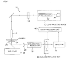
- Fig. 6 is an outlined diagram showing the structure of a near-field polarized-light measurement apparatus (light-emitting type) according to a first embodiment of the present invention.
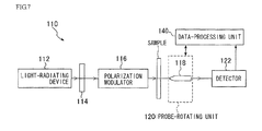
- Fig. 7 is a diagram showing the structure of a near-field polarized-light measurement apparatus (light-collecting type) according to a second embodiment of the present invention.
- First, in order to ascertain whether it was possible to measure optical rotation using near-field light, the inventors conducted experiments to investigate the polarized-light transfer characteristics of a near-field probe. The probe used in these experiments had an elliptical or slit-shaped opening, as shown in Figs. 1A and 1B or Fig. 2, respectively. (See
Japanese Unexamined Patent Application Publication No. 2002-162333 field probe 50 having an elliptical opening, and Fig. 1B is a top view thereof. Fig. 2 is a perspective view of the near-field probe 50 when it has a slit-shaped opening. The near field-probe 50 shown in Figs. 1A, 1B, and 2 is constituted by apointed portion 52 which is formed by tapering the end of an optical fiber having an elliptical or slit-shaped core in a substantially conical shape. A gold (Au) thin film is formed on the surface of the near-field probe 50 to serve as amask 54. An elliptical or slit-shaped opening 56 for obtaining linearly polarized light in a predetermined oscillation direction is formed at the extreme tip of the substantially conicaltapered portion 52. With this structure, the near-field probe 50 in Figs. 1A, 1B, and 2 can selectively emit or collect linearly polarized light that is polarized in a predetermined direction (orthogonal to the longitudinal direction of the opening 56). - Fig. 3 shows the configuration of an apparatus used in the experiments. In the apparatus in Fig. 3, laser light from a He-Ne laser passes through a polarizer, a half-wave plate, and an objective lens and irradiates the opening of the near-field probe described above, and the light collected at the opening is detected with a detector. The near-field probe used in the experiments has an elliptical opening with a short axis of 50 nm and a long axis of 500 nm (see Figs. 1A and 1B). The half-wave plate was rotated about the optical axis to vary the angle of the plane of polarization with respect to the long axis of the opening in the near-field probe, and the collection efficiency at that time was measured. Fig. 4 shows spectra of the light collected by the probe when the plane of polarization was rotated by 10°, 30°, 60°, and 90°. Figs. 5A and 5B respectively show spectra and integrated intensity when the plane of polarization was varied from 0° to 2°. It is evident from these figures that the near-field probe has good polarization selectivity. In other words, it is clear that superior optical rotation measurement can be accomplished using the near-field probe described above, even for near-field light.
- Furthermore, an experiment was also carried out using the near-field probe in a light-emitting mode, and good polarization selectivity was obtained in this case too.
- The present invention has been conceived in light of the findings described above. Preferred embodiments will now be described below with reference to the drawings.
- Fig. 6 is an outlined diagram showing the configuration of a near-field polarized-
light measurement apparatus 10 according to a first embodiment of the present invention. The near-field polarized-light measurement apparatus 10 includes a light-radiatingdevice 12, a near-field probe 14, apolarization modulator 16, ananalyzer 18, an analyzer-rotatingunit 20, and adetector 22. Linearly polarized light emitted from the light-radiatingdevice 12 enters the near-field probe 14 from an entrance end and is guided inside the near-field probe 14. The light guided in the near-field probe 14 generates near-field light at the opening in the tip of theprobe 14. This linearly polarized near-field light then irradiates a sample. The linearly polarized light that passes through the sample is collected by anobjective lens 24, is reflected at amirror 26 such as dichroic mirror, passes through alens 28, and reaches thepolarization modulator 16. Linearly polarized, whose plane of polarization is modulated at a predetermined modulation frequency upon transmission through thepolarization modulator 16, passes through theanalyzer 18 and is detected at thedetector 22. Theanalyzer 18 is configured so that the transmission axis thereof can be rotated on the optical axis using the analyzer-rotatingunit 20. - The light-radiating
device 12 is formed of alight source 30 and aspectroscope 32. Light from thelight source 30 is divided into spectral components by thespectroscope 32, and wavelength scanning is performed to measure the spectral dependency of the optical rotation (optical rotatory dispersion). Apolarizer 34 is disposed after the light-radiatingdevice 12 to linearly polarize the light to be guided in the near-field probe 14. The present embodiment is illustrated by an example where thespectroscope 32 is placed at the light-emission side, but it may be placed at thedetector 22 side so that only light of predetermined wavelengths in the light transmitted through the sample is detected at thedetector 22. - A polarized-light probe having an elliptical or slit-shaped opening, as shown in Figs. 1A and 1B or Fig. 2, is used as the near-
field probe 14 in the present embodiment (seeJapanese Unexamined Patent Application Publication No. 2002-162333 device 12 passes through thepolarizer 34 and is guided in theprobe 14 may be used. However, in a standard optical-fiber-based probe, the polarization state of laser light is destroyed due to changes in the optical fiber curvature, length, and so on, and therefore, it is preferable to use a polarized-light probe, such as that described in the present embodiment. - The
polarization modulator 16 is formed of a modulator such as a Faraday cell, an oscillator for oscillating the Faraday cell at a predetermined modulation frequency, and so on. The polarization modulator 16 thus oscillates the orientation of the plane of polarization of the linearly polarized light at a predetermined modulation frequency. - The analyzer-rotating
unit 20 is formed of a gear, a servo motor, and so forth, and rotates theanalyzer 18 about the optical axis to vary the direction of the transmission axis thereof. The amount of rotation of theanalyzer 18 is sent to a data-processingunit 40. - The light transmitted through the
analyzer 18 is detected in thedetector 22, and a detection signal therefrom is sent to the data-processingunit 40. Measurement of the optical rotation of the sample is performed in the data-processingunit 40 based on the detection signal from thedetector 22 by rotating theanalyzer 18. - Furthermore, the near-field polarized-
light measurement apparatus 10 according to the present embodiment also includes an XYZ stage 36 (moving mechanism) for controlling the positional relationship of the sample and theprobe 14. The sample, theobjective lens 24, and themirror 26 are mounted on theXYZ stage 36, and theXYZ stage 36 moves these components in the horizontal directions (X and Y directions) and the vertical direction (Z direction). Accordingly, by moving the position of the tip of the near-field probe 14 relative to the measurement surface of the sample, in the X and Y directions orthogonal to the normal thereof, to change the measurement position on the sample surface, it is possible to perform mapping measurement of the optical rotation and optical rotatory dispersion. - Measurement of the optical rotation is carried out as follows. First, in the absence of the sample, the direction of the transmission axis of the
analyzer 18 is adjusted using the analyzer-rotatingunit 20 so that the transmission axes of the polarizer and the analyzer are perpendicular to each other, in other words, so that the detected light is minimized. Then, after inserting the sample, it is irradiated with linearly polarized near-field light from the near-field probe 14. The light transmitted through the sample is collected by theobjective lens 24 and is directed to thepolarization modulator 16. Light whose polarization is modulated at the predetermined modulation frequency by thepolarization modulator 16 then passes through theanalyzer 18 and is detected at thedetector 22. The data-processingunit 40 then rotates the transmission axis of theanalyzer 18 using the analyzer-rotatingunit 20 so that, in the detection signal from thedetector 22, a frequency component equal to the modulation frequency of thepolarization modulator 16 is eliminated. The rotation angle is measured from the angle of the transmission axis at that point. - According to the near-field polarized-
light measurement apparatus 10 of the present embodiment, as described above, because the optical rotation or optical rotatory dispersion of the sample is measured using a near-field optical technique, it is possible to measure the optical rotation or optical rotatory dispersion with a spatial resolution surpassing the diffraction limit of light. - Also, the present embodiment is configured such that the
polarization modulator 16 for oscillating the plane of polarization of the linearly polarized light at the predetermined frequency is provided in the optical path between the light-radiatingdevice 12 and thedetector 22, and the optical rotation or optical rotatory dispersion of the sample is measured with symmetric angular oscillation method using the optical-null principle. With this method, it is possible to attain a resolution of ±0.1 degree when measuring the optical rotation. - In the embodiment described above, the
polarization modulator 16 is disposed in the optical path, and the optical rotation or optical rotatory dispersion of the sample is measured with symmetric angular oscillation method using the optical-null principle; however, instead of providing thepolarization modulator 16, a configuration in which the optical rotation or optical rotatory dispersion is measured from the rotation angle of theanalyzer 18 is also possible (the crossed-Nicol method). More specifically, the optical rotation may be obtained by the following procedure: First a reference configuration is determined; in this configuration, the transmission axes of thepolarizer 34 andanalyzer 18 are positioned so that, in the absence of the sample, the detected light level is minimized. Then, with the sample in place, the optical rotation is determined from the rotation angle of theanalyzer 18 where the detected light level is minimized. Alternatively, theanalyzer 18 may be rotated or oscillated to determine the optical rotation from the detection signal component corresponding to double the frequency of the angular frequency thereof. However, in view of the measurement precision, it is preferable to employ the symmetric angle-oscillating method, as in the embodiment described above. The measurement precision of the crossed-Nicol method is generally about ±0.5 degree, whereas a measurement precision as high as ±0.1 degree can be attained with the embodiment described above. - The first embodiment is illustrated by using the near-field probe to radiate light; however, the apparatus may be configured using a near-field probe to collect light. Fig. 7 is a diagram of a second embodiment in which a near-field probe is used to collect light.
- A near-field polarized-
light measurement apparatus 110 in Fig. 7 includes a light-radiatingdevice 112 for irradiating a sample with light; apolarizer 114, disposed after the light-radiatingdevice 112, for linearly polarizing the light irradiating the sample; apolarization modulator 116, disposed after thepolarizer 114, for changing the orientation of the plane of polarization of the linearly polarized light; a near-field probe 118 for collecting the linearly polarized light transmitted through the sample; a probe-rotating unit 120 (light-collection-direction rotating unit) for rotating the near-field probe 118 about the optical axis to change the angle of a transmission axis thereof; and adetector 112 for detecting the light collected by the near-field probe 118. Also in this embodiment, a probe having an elliptical or slit-shaped opening, as shown in Figs. 1A and 1B or Fig. 2, is used as the near-field probe 118. - The light emitted from the light-radiating
device 112 becomes linearly polarized light having a plane of polarization in a predetermined direction upon passing through thepolarizer 114. The plane of polarization of this linearly polarized light is modulated at a predetermined frequency by thepolarization modulator 116, and the modulated linearly polarized light is collected by a collecting lens or the like (not shown) and irradiates the sample. The light transmitted through the sample is collected by the near-field probe 118 and is detected at thedetector 122. The detected data is then sent to a data-processing unit 140. The near-field probe 118 selectively collects linearly polarized light in a predetermined direction and functions as the analyzer shown in the embodiment in Fig. 6. To do so, the probe-rotatingunit 120 is provided as a light-collection-direction rotating unit for varying the angle of the linearly polarized light collected at the near-field probe 118. Information about the angle of orientation of the collected linearly polarized light is also sent to the data-processing unit 140. Other possible forms of the light-collection-direction rotating unit include a configuration in which light from the sample is collected with the near-field probe after passing through an analyzer and the analyzer is rotated about the optical axis. - Measurement of the optical rotation of the sample is performed in the same way as in the embodiment shown in Fig. 6. First, in the absence of the sample, the orientation of the transmission axis of the near-
field probe 118 is adjusted by the probe-rotatingunit 120 so that the transmission axis of thepolarizer 114 and the transmission axis of the near-field probe 118 are orthogonal, in order to minimize the level of light detected. In the present embodiment, a probe having an elliptical or slit-shaped opening is used as the near-field probe 118; a direction orthogonal to the longitudinal direction of this opening is the transmission-axis direction of the probe, and linearly polarized light in this transmission-axis direction is selectively collected. Thus, the transmission-axis direction is varied by rotating the near-field probe 118 about the optical axis using the probe-rotatingunit 120. Then, the sample is put in place and light transmitting through the sample is collected by the near-field probe 118. The data-processing unit 140 rotates the transmission axis of the near-field probe 118 (the direction of the short-axis of the opening) by means of the probe-rotatingunit 120 so that, in a detection signal from thedetector 122, a frequency component equal to the modulation frequency of thepolarization modulator 116 is eliminated. The rotation angle is measured from the angle of the transmission axis at that point. - In this way, it is also possible to perform superior optical rotation measurement when a near-field probe is used in the light-collecting mode. Furthermore, because the transmission efficiency of a near-field probe having an opening is generally low, there is a risk of the light not reaching the detector when using a sample having poor transmittance in the light-radiating mode. However, because the sample can be strongly irradiated with light using the configuration in the second embodiment, it is possible to perform satisfactory measurement, even of a sample having poor transmittance.
- In the first and second embodiments described above, a polarized-light probe having a slit-shaped or elliptical opening was used (see Figs. 1A and 1B or Fig. 2). By using such a polarized-light probe, it is possible to stably emit and detect linearly polarized light. However, in a standard optical-fiber-based probe, the polarization state of laser light is destroyed due to changes in the fiber curvature, length, and so forth, and therefore, it is not possible to utilize the coherence characteristics of the laser light. Furthermore, although the detection sensitivity increases as the near-field light emitted from a minute aperture becomes more linearly polarized, in a standard probe, the near-field light becomes elliptically polarized, and the sensitivity thus decreases. In contrast, when using a polarized-light probe like that in the present invention, the polarization state of the laser light is not destroyed, and it is thus possible to emit and detect near-field light with a stable polarization state.
Claims (9)
- A near-field polarized-light measurement apparatus comprising:a near-field probe having at a tip thereof an opening smaller than the wavelength of light used for measurement, for generating linearly polarized near-field light from the opening and irradiating a sample with the near-field light;an analyzer;a detector for detecting light transmitted through the sample via the analyzer; andan analyzer-rotating unit for rotating the analyzer about an optical axis to vary the angle of a transmission axis thereof,wherein optical rotation of the sample is measured by rotating the analyzer with the analyzer-rotating unit.
- A near-field polarized-light measurement apparatus according to Claim 1, further comprising:a polarization modulator disposed before the analyzer, for varying the orientation of a plane of polarization of the linearly polarized light at a predetermined modulation frequency,wherein, based on a frequency component corresponding to the modulation frequency of the polarization modulator and/or higher harmonic frequencies thereof in a detection signal from the detector, the transmission axis of the analyzer is rotated by the analyzer-rotating unit, and the optical rotation of the sample is measured from rotation angle information of the analyzer.
- A near-field polarized-light measurement apparatus comprising:a light-radiating device for irradiating a sample with light;a polarizer disposed after the light-radiating device, for linearly polarizing the light irradiating the sample;a near-field probe having at a tip thereof an opening smaller than the wavelength of light used for measurement, for collecting the linearly polarized light transmitted through the sample from the opening;a light-collection-direction rotating unit for changing the angle of the linearly polarized light collected at the near-field probe; anda detector for detecting the light collected by the near-field probe,wherein optical rotation of the sample is measured.
- A near-field polarized-light measurement apparatus according to Claim 3, further comprising:a polarization modulator disposed in an optical path between the polarizer and the detector, for changing the orientation of a plane of polarization of the linearly polarized light,wherein, based on a frequency component corresponding to a modulation frequency of the polarization modulator and/or higher harmonic frequencies thereof in a detection signal from the detector, the angle of the linearly polarized light collected at the near-field probe is changed by the light-collection-direction rotating unit, and the optical rotation of the sample is measured from rotation angle information.
- A near-field polarized-light measurement apparatus according to one of Claims 2 and 4, wherein the polarization modulator is formed of a Faraday cell.
- A near-field polarized-light measurement apparatus according to one of Claims 1 to 5, wherein the near-field probe selectively generates or collects linearly polarized light.
- A near-field polarized-light measurement apparatus according to Claim 6, wherein the opening in the near-field probe is elliptical or slit-shaped.
- A near-field polarized-light measurement apparatus according to one of Claims 1 to 7, further comprising:a spectroscope for splitting the light irradiating the sample or the light detected at the detector into spectral components,wherein the optical rotatory dispersion of the sample is measured.
- A near-field polarized-light measurement apparatus according to one of Claims 1 to 8, further comprising:a moving mechanism for moving the position of the tip of the near-field probe relative to a measurement surface of the sample in X and Y directions orthogonal to a normal thereof,wherein mapping measurement is performed for the measurement surface of the sample.
Applications Claiming Priority (1)
| Application Number | Priority Date | Filing Date | Title |
|---|---|---|---|
| JP2005122311A JP4791752B2 (en) | 2005-04-20 | 2005-04-20 | Near-field polarimeter |
Publications (2)
| Publication Number | Publication Date |
|---|---|
| EP1715322A2 true EP1715322A2 (en) | 2006-10-25 |
| EP1715322A3 EP1715322A3 (en) | 2007-04-11 |
Family
ID=36607493
Family Applications (1)
| Application Number | Title | Priority Date | Filing Date |
|---|---|---|---|
| EP06111974A Withdrawn EP1715322A3 (en) | 2005-04-20 | 2006-03-30 | Near-field polarized-light measurement apparatus |
Country Status (3)
| Country | Link |
|---|---|
| US (1) | US7586606B2 (en) |
| EP (1) | EP1715322A3 (en) |
| JP (1) | JP4791752B2 (en) |
Cited By (2)
| Publication number | Priority date | Publication date | Assignee | Title |
|---|---|---|---|---|
| CN101241070B (en) * | 2008-03-11 | 2011-08-17 | 上海理工大学 | Polarimeter for measuring optically-active rotation angle and its measurement method |
| CN102928082A (en) * | 2012-11-06 | 2013-02-13 | 北京航空航天大学 | Faraday detection method for removing modulation amplitude and light-intensity variation influences |
Families Citing this family (7)
| Publication number | Priority date | Publication date | Assignee | Title |
|---|---|---|---|---|
| JP5067754B2 (en) * | 2007-08-03 | 2012-11-07 | 独立行政法人理化学研究所 | Near-field microscope and its spectroscopic / image acquisition method |
| JP2010117163A (en) * | 2008-11-11 | 2010-05-27 | Horiba Ltd | Polarimeter and method for calibrating polarimeter |
| JP2010117164A (en) * | 2008-11-11 | 2010-05-27 | Horiba Ltd | Polarimeter |
| JP5289989B2 (en) * | 2009-01-27 | 2013-09-11 | 日本分光株式会社 | Phase difference measuring device |
| JP2010286309A (en) * | 2009-06-10 | 2010-12-24 | Toshiba Corp | Method of inspecting template for nanoimprint |
| JP6661109B1 (en) * | 2018-12-05 | 2020-03-11 | 株式会社テクノホロン | Damage detection mechanism |
| WO2020255868A1 (en) * | 2019-06-20 | 2020-12-24 | 学校法人慶應義塾 | Polarimetry device and polarimetry chip |
Citations (2)
| Publication number | Priority date | Publication date | Assignee | Title |
|---|---|---|---|---|
| JPS55103434A (en) | 1979-02-01 | 1980-08-07 | Japan Spectroscopic Co | Polarimeter |
| JP2002162333A (en) | 2000-11-28 | 2002-06-07 | Jasco Corp | Near field probe, manufacturing method of near field probe and near field microscope using near field probe |
Family Cites Families (5)
| Publication number | Priority date | Publication date | Assignee | Title |
|---|---|---|---|---|
| DE69126160T2 (en) * | 1990-03-16 | 1997-10-09 | Canon Kk | Optical information recording / reproducing apparatus |
| JPH10325840A (en) * | 1997-05-23 | 1998-12-08 | Seiko Instr Inc | Scanning near-field microscope utilizing polarization |
| JPH1164214A (en) * | 1997-08-26 | 1999-03-05 | Jasco Corp | Angle-of-rotation measuring instrument |
| JP2000304521A (en) * | 1999-04-22 | 2000-11-02 | Jasco Corp | Angle gauge and polarimeter using the same |
| US20030184750A1 (en) * | 2002-04-02 | 2003-10-02 | Aikens David M. | Ellipsometer or reflectometer with elliptical aperture |
-
2005
- 2005-04-20 JP JP2005122311A patent/JP4791752B2/en not_active Expired - Fee Related
-
2006
- 2006-03-30 EP EP06111974A patent/EP1715322A3/en not_active Withdrawn
- 2006-04-05 US US11/398,096 patent/US7586606B2/en not_active Expired - Fee Related
Patent Citations (2)
| Publication number | Priority date | Publication date | Assignee | Title |
|---|---|---|---|---|
| JPS55103434A (en) | 1979-02-01 | 1980-08-07 | Japan Spectroscopic Co | Polarimeter |
| JP2002162333A (en) | 2000-11-28 | 2002-06-07 | Jasco Corp | Near field probe, manufacturing method of near field probe and near field microscope using near field probe |
Cited By (3)
| Publication number | Priority date | Publication date | Assignee | Title |
|---|---|---|---|---|
| CN101241070B (en) * | 2008-03-11 | 2011-08-17 | 上海理工大学 | Polarimeter for measuring optically-active rotation angle and its measurement method |
| CN102928082A (en) * | 2012-11-06 | 2013-02-13 | 北京航空航天大学 | Faraday detection method for removing modulation amplitude and light-intensity variation influences |
| CN102928082B (en) * | 2012-11-06 | 2014-07-30 | 北京航空航天大学 | Faraday detection method for removing modulation amplitude and light-intensity variation influences |
Also Published As
| Publication number | Publication date |
|---|---|
| JP4791752B2 (en) | 2011-10-12 |
| JP2006300708A (en) | 2006-11-02 |
| EP1715322A3 (en) | 2007-04-11 |
| US20060238758A1 (en) | 2006-10-26 |
| US7586606B2 (en) | 2009-09-08 |
Similar Documents
| Publication | Publication Date | Title |
|---|---|---|
| US7586606B2 (en) | Near-field polarized-light measurement apparatus | |
| US7463364B2 (en) | Electro-optic sensor | |
| JP3002977B1 (en) | Scanning probe and scanning probe microscope | |
| JP6245600B2 (en) | Polarization sensitive terahertz wave detector | |
| US6985227B2 (en) | Birefringence measurement at deep-ultraviolet wavelengths | |
| JP2006317349A (en) | Optical sensing system | |
| CN111060719A (en) | Terahertz pulse beam extraction mechanism of terahertz near-field microscope | |
| JP4498081B2 (en) | Scattering near-field microscope and measuring method thereof | |
| JP4119411B2 (en) | Photothermal conversion measuring apparatus and method | |
| JP2010223586A (en) | Terahertz spectrometric instrument and method for terahertz spectrometry | |
| KR100380766B1 (en) | Method for evaluating displaying element of liquid crystal, information storage medium for storing computer program representative of the method and evaluating system using the same | |
| EP3709002A1 (en) | Spectroscopic analysis device | |
| JP4560627B2 (en) | Scattered light detection method and scanning probe microscope | |
| WO2006001842A2 (en) | Electro-optic sensor | |
| JPS63236945A (en) | Crystal bearing analysis instrument which utilizes polarization characteristic of raman scattering light | |
| JPH10115573A (en) | Method and apparatus for measurement of tertiary nonlinear susceptibility rate | |
| JP3940376B2 (en) | Spectrometer for gel sample | |
| US6867863B1 (en) | Integrated diagnostic for photoelastic modulator | |
| JP2002540417A (en) | Integrated diagnostic device for photoelastic modulator | |
| JP5289989B2 (en) | Phase difference measuring device | |
| JP4703841B2 (en) | Near-field probe, manufacturing method thereof, and near-field microscope using the near-field probe | |
| JP2001074649A (en) | Method for measuring angle of optical rotation, and method for inspecting urine | |
| WO2023021867A1 (en) | Scanning probe microscope, and specimen used in same | |
| JP5100248B2 (en) | Atomic force microscope | |
| JP2003106978A (en) | Optical radiation pressure measuring device |
Legal Events
| Date | Code | Title | Description |
|---|---|---|---|
| PUAI | Public reference made under article 153(3) epc to a published international application that has entered the european phase |
Free format text: ORIGINAL CODE: 0009012 |
|
| AK | Designated contracting states |
Kind code of ref document: A2 Designated state(s): AT BE BG CH CY CZ DE DK EE ES FI FR GB GR HU IE IS IT LI LT LU LV MC NL PL PT RO SE SI SK TR |
|
| AX | Request for extension of the european patent |
Extension state: AL BA HR MK YU |
|
| PUAL | Search report despatched |
Free format text: ORIGINAL CODE: 0009013 |
|
| AK | Designated contracting states |
Kind code of ref document: A3 Designated state(s): AT BE BG CH CY CZ DE DK EE ES FI FR GB GR HU IE IS IT LI LT LU LV MC NL PL PT RO SE SI SK TR |
|
| AX | Request for extension of the european patent |
Extension state: AL BA HR MK YU |
|
| RIC1 | Information provided on ipc code assigned before grant |
Ipc: G01J 4/02 20060101ALI20070306BHEP Ipc: G12B 21/06 20060101ALI20070306BHEP Ipc: G01N 13/14 20060101AFI20060707BHEP |
|
| AKX | Designation fees paid | ||
| STAA | Information on the status of an ep patent application or granted ep patent |
Free format text: STATUS: THE APPLICATION IS DEEMED TO BE WITHDRAWN |
|
| 18D | Application deemed to be withdrawn |
Effective date: 20071012 |
|
| REG | Reference to a national code |
Ref country code: DE Ref legal event code: 8566 |