EP1713205A1 - Controlling connectivity of a wireless smart card reader - Google Patents
Controlling connectivity of a wireless smart card reader Download PDFInfo
- Publication number
- EP1713205A1 EP1713205A1 EP05103026A EP05103026A EP1713205A1 EP 1713205 A1 EP1713205 A1 EP 1713205A1 EP 05103026 A EP05103026 A EP 05103026A EP 05103026 A EP05103026 A EP 05103026A EP 1713205 A1 EP1713205 A1 EP 1713205A1
- Authority
- EP
- European Patent Office
- Prior art keywords
- smart card
- card reader
- mobile device
- connections
- user
- Prior art date
- Legal status (The legal status is an assumption and is not a legal conclusion. Google has not performed a legal analysis and makes no representation as to the accuracy of the status listed.)
- Granted
Links
Images

Classifications
-
- H—ELECTRICITY
- H04—ELECTRIC COMMUNICATION TECHNIQUE
- H04L—TRANSMISSION OF DIGITAL INFORMATION, e.g. TELEGRAPHIC COMMUNICATION
- H04L63/00—Network architectures or network communication protocols for network security
- H04L63/08—Network architectures or network communication protocols for network security for authentication of entities
- H04L63/0853—Network architectures or network communication protocols for network security for authentication of entities using an additional device, e.g. smartcard, SIM or a different communication terminal
-
- H—ELECTRICITY
- H04—ELECTRIC COMMUNICATION TECHNIQUE
- H04W—WIRELESS COMMUNICATION NETWORKS
- H04W12/00—Security arrangements; Authentication; Protecting privacy or anonymity
- H04W12/08—Access security
-
- H—ELECTRICITY
- H04—ELECTRIC COMMUNICATION TECHNIQUE
- H04W—WIRELESS COMMUNICATION NETWORKS
- H04W12/00—Security arrangements; Authentication; Protecting privacy or anonymity
- H04W12/50—Secure pairing of devices
-
- H—ELECTRICITY
- H04—ELECTRIC COMMUNICATION TECHNIQUE
- H04L—TRANSMISSION OF DIGITAL INFORMATION, e.g. TELEGRAPHIC COMMUNICATION
- H04L63/00—Network architectures or network communication protocols for network security
- H04L63/08—Network architectures or network communication protocols for network security for authentication of entities
- H04L63/083—Network architectures or network communication protocols for network security for authentication of entities using passwords
-
- H—ELECTRICITY
- H04—ELECTRIC COMMUNICATION TECHNIQUE
- H04W—WIRELESS COMMUNICATION NETWORKS
- H04W12/00—Security arrangements; Authentication; Protecting privacy or anonymity
- H04W12/06—Authentication
-
- H—ELECTRICITY
- H04—ELECTRIC COMMUNICATION TECHNIQUE
- H04W—WIRELESS COMMUNICATION NETWORKS
- H04W76/00—Connection management
- H04W76/10—Connection setup
-
- H—ELECTRICITY
- H04—ELECTRIC COMMUNICATION TECHNIQUE
- H04W—WIRELESS COMMUNICATION NETWORKS
- H04W88/00—Devices specially adapted for wireless communication networks, e.g. terminals, base stations or access point devices
- H04W88/02—Terminal devices
- H04W88/04—Terminal devices adapted for relaying to or from another terminal or user
Definitions
- Smart cards are personalized security devices, defined by the IS07816 standard and its derivatives, as published by the International Organization for Standardization.
- a smart card may have a form factor of a credit card and may include a semiconductor device.
- the semiconductor device may include a memory that can be programmed with security information (e.g., a private decryption key, a private signing key, biometrics, etc.) and may include a processor and/or dedicated logic, for example, dedicated decryption logic and/or dedicated signing logic.
- a smart card may include a connector for powering the semiconductor device and performing serial communication with an external device.
- smart card functionality may be embedded in a device having a different form factor and different communication protocol, for example a Universal Serial Bus (USB) device.
- USB Universal Serial Bus
- Access to security information stored on a smart card is controlled by the processor and/or dedicated logic on the smart card.
- a smart card reader communicates with the processor and/or dedicated logic in order to access the security information stored on the smart card. It may be prudent, therefore, to ensure that access to the smart card reader (with the smart card inserted therein) is controlled.
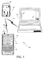
- FIG. 1 is a schematic illustration of a system including a wireless-enabled smart card reader and other devices, according to some embodiments of the invention
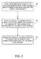
- FIG. 2 is a flowchart illustration of a method to be implemented in the system of FIG. 1, according to some embodiments of the invention
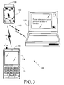
- FIG. 3 is a schematic illustration of a system including a wireless-enabled smart card reader and other devices, according to other embodiments of the invention.
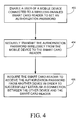
- FIG. 4 is a flowchart illustration of a method to be implemented in the system of FIG. 3, according to some embodiments of the invention.
- FIG. 5 is a block diagram of the smart card reader and mobile device of FIG. 1 or FIG. 3, according to some embodiments of the invention.
- FIG. 1 is a schematic diagram of an exemplary system, according to some embodiments of the invention.
- a system 100 includes a wireless smart card reader 102 and a mobile device 104.
- Smart card reader 102 and mobile device 104 are able to communicate over a wireless communication link 106.
- a non-exhaustive list of examples of wireless local area network standards for wireless communication link 106 includes the Institute of Electrical and Electronic Engineers (IEEE) for Wireless LAN MAC and Physical layer (PHY) 802.11 a, b, g and n specifications or future related standards, the Bluetooth® standard, the ZigbeeTM standard and the like.
- IEEE Institute of Electrical and Electronic Engineers
- PHY Physical layer
- a smart card 108 is shown inserted into smart card reader 102.
- Smart card 108 may also include a random number generator.
- mobile device 104 may be able to send and receive e-mail messages via an e-mail server (not shown). If, for example, the Secure Multipurpose Internet Mail Extensions (S/MIME) protocol is used, e-mail messages received at mobile device 104 are encrypted using a symmetric algorithm with a random message key generated by the sender of the e-mail message. The e-mail message also includes the message key, encrypted using the public key of the recipient. Upon receipt of an encrypted e-mail message, mobile device 104 may extract the encrypted message key and send it to smart card reader 102 via communication link 106.
- S/MIME Secure Multipurpose Internet Mail Extensions
- Smart card reader 102 may send the encrypted message key to smart card 108, and the decryption engine of smart card 108 may decrypt the encrypted message key using the recipient's private decryption key, which is stored in smart card 108.
- Smart card reader 102 may retrieve the decrypted message key from smart card 108 and forward it to mobile device 104 via communication link 106 so that mobile device 104 can decrypt the received e-mail message.
- the smart card 108 may prevent unauthorized use of the recipient's private decryption key by requiring that a password or personal identification number (PIN) be supplied before allowing the decryption operation to proceed.
- PIN personal identification number
- mobile device 104 may send a hash of the contents of the e-mail message to smart card reader 102 over communication link 106.
- Smart card reader 102 may pass the hash to smart card 108, which may produce a digital signature from the hash and the sender's private signing key, which is stored in smart card 108.
- Smart card 108 may then pass the digital signature to smart card reader 102, which may forward it to mobile device 104 via communication link 106 so that mobile device 104 can transmit it along with the e-mail message to the e-mail server.
- smart card 108 may prevent unauthorized use of the recipient's private signing key by requiring that a password or PIN be supplied before allowing the signing operation to proceed.
- the unencrypted message key should be sent securely over communication link 106 from smart card reader 102 to mobile device 104 to prevent a third party from retrieving the message key from communication link 106.
- the hash to be signed should be sent authentically over communication link 106 from smart card reader 102 to mobile device 104 to prevent a third party from modifying the hash and thereby causing smart card 108 to produce a signature using a hash different from the hash of the intended message. Therefore communication link 106 may need to be secured using cryptographic techniques.
- the person whose security information is stored on smart card 108 may also wish to digitally sign outgoing e-mail sent from a personal computer (not shown) or to decrypt incoming encrypted e-mail received at the personal computer. This will require the personal computer to communicate with smart card reader 102 in much the same way as mobile device 104 communicates with smart card reader 102 as described above. For this purpose, or for other security-related measures (e.g. to permit the person to unlock the personal computer), the communication link between the personal computer and smart card reader 102 may need to be secured using cryptographic techniques.
- Smart card reader 102 may be able to maintain dual wireless connections concurrently, one connection to mobile device 104 and another to the personal computer. However, if an attacker were to steal smart card reader 102, establish a wireless connection between smart card reader 102 and another device, and return smart card reader 102 to its rightful user, then as long as smart card reader 102 is within range of the other device, the attacker would have access to smart card reader 102 and smart card 108 without the rightful user of smart card reader 102 being aware of this. Another possibility is that the attacker, having stolen smart card reader 102, could pair smart card reader 102 with the other device in such a way as to facilitate establishment of a wireless connection between smart card reader 102 and the other device, and then return smart card reader 102 to its rightful user.
- the pairing may occur in a manner that is not wireless, for example, using a USB cable to connect smart card reader 102 briefly to the other device.
- the USB cable may be removed, smart card reader 102 may be returned to its rightful user, and a wireless connection between smart card reader 102 and the other device may exist as long as smart card reader 102 is within range of the other device.
- One way to handle this potential security issue is to restrict to one the number of wireless connections that smart card reader 102 can make at any given time.
- an attacker establishes a wireless connection 110 between smart card reader 102 and another device, for example, a personal computer 112 belonging to the attacker, the rightful user of smart card reader 102 will be unable to establish a wireless connection between smart card reader 102 and mobile device 104 and will therefore be aware that something is wrong.
- the rightful user could repair mobile device 104 and smart card reader 102, thereby removing the existing wireless connection between smart card reader 102 and the other device.
- the rightful user may notify an administrator of the problem.
- Another way to handle this potential security issue is to control the connectivity of smart card reader 102 via mobile device 104 while still enabling smart card reader 102 to maintain more than one wireless connection at a time.
- mobile device 104 may query smart card reader 102 from time to time about any other wireless connections currently maintained by smart card reader 102 (202).
- Mobile device 104 may show on its display 114 a notification if the information about other wireless connections changes (204). For example, if a new wireless connection is established between smart card reader 102 and another device, display 114 may show a notification such as "Note: Your Smart Card Reader is now connected with a new device". The user may then have the option to review current wireless connections maintained by smart card reader 102 and optionally cancel one or more of the connections (206). Canceling a connection may result in the deletion of pairing keys for that connection.
- mobile device 104 may enable its user to set, via an input component, for example a keyboard 116, an authorization password for subsequent connections to smart card reader 102 (402).
- Mobile device 104 could send the authorization password securely over communication link 106 to smart card reader 102 (404), and then all subsequent attempts to connect, either wirelessly or via a wired connection, for example a USB cable, to smart card reader 102 will lead to the user of the device trying to connect to smart card reader 102 being prompted for the authorization password (406). If an attacker steals smart card reader 102 and attempts to establish a connection between smart card reader 102 and another device, the attacker will be required to enter the authorization password at the other device in order for the connection to be established successfully (406).
- Figure 5 is a block diagram of portions of system 100, according to some embodiments of the invention. For clarity, some components of mobile device 104 and smart card reader 102 are not shown in Figure 5 and are not described explicitly below.
- Mobile device 104 includes an antenna 502 and smart card reader 102 includes an antenna 512.
- antennae 502 and 512 includes dipole antennae, monopole antennae, multilayer ceramic antennae, planar inverted-F antennae, loop antennae, shot antennae, dual antennae, omnidirectional antenna and any other suitable antennae.
- Mobile device 104 also includes a communication interface 504 coupled to antenna 502.
- Smart card reader 102 includes a communication interface 514 coupled to antenna 512.
- a non-exhaustive list of examples for standards with which communication interfaces 504 and 514 may be compatible includes 802.11 a, b, g and n and future related standards, the Bluetooth® standard, the ZigbeeTM standard and the like.
- Mobile device 104 also includes a processor 506 coupled to communication interface 504, to display 114 and to keyboard 116.
- Mobile device 104 also includes a memory 508, which may be fixed in or removable from mobile device 104.
- Memory 508 may be coupled to processor 506 or partly embedded in processor 506.
- Communication interface 504 and processor 506 may be part of the same integrated circuit or in separate integrated circuits.
- processor 506 and memory 508 may be part of the same integrated circuit or in separate integrated circuits.
- Smart card reader 102 also includes a processor 516 coupled to communication interface 514.
- Smart card reader 102 also includes a memory 518, which may be fixed in or removable from smart card reader 102.
- Memory 518 may be coupled to processor 516 or partly embedded in processor 516.
- Communication interface 514 and processor 516 may be part of the same integrated circuit or in separate integrated circuits.
- processor 516 and memory 518 may be part of the same integrated circuit or in separate integrated circuits.
- processors 506 and 516 includes a central processing unit (CPU), a digital signal processor (DSP), a reduced instruction set computer (RISC), a complex instruction set computer (CISC) and the like. Furthermore, processors 506 and 516 may be part of an application specific integrated circuit (ASIC) or may be a part of an application specific standard product (ASSP).
- CPU central processing unit
- DSP digital signal processor
- RISC reduced instruction set computer
- CISC complex instruction set computer
- processors 506 and 516 may be part of an application specific integrated circuit (ASIC) or may be a part of an application specific standard product (ASSP).
- ASIC application specific integrated circuit
- ASSP application specific standard product
- a non-exhaustive list of examples for memories 508 and 518 includes any combination of the following:
- Memory 508 may store executable code 509 which, when executed by processor 506, may cause mobile device 104 to implement relevant portions of any or a combination of the methods of Figures 2 and 4.
- Memory 518 may store executable code 519 which, when executed by processor 516, may cause smart card reader 102 to implement relevant portions of any or a combination of the methods of Figures 2 and 4.
Abstract
Description
- Smart cards are personalized security devices, defined by the
IS07816 - Access to security information stored on a smart card is controlled by the processor and/or dedicated logic on the smart card. A smart card reader communicates with the processor and/or dedicated logic in order to access the security information stored on the smart card. It may be prudent, therefore, to ensure that access to the smart card reader (with the smart card inserted therein) is controlled.
- Embodiments of the invention are illustrated by way of example and not limitation in the figures of the accompanying drawings, in which like reference numerals indicate corresponding, analogous or similar elements, and in which:
- FIG. 1 is a schematic illustration of a system including a wireless-enabled smart card reader and other devices, according to some embodiments of the invention;
- FIG. 2 is a flowchart illustration of a method to be implemented in the system of FIG. 1, according to some embodiments of the invention;
- FIG. 3 is a schematic illustration of a system including a wireless-enabled smart card reader and other devices, according to other embodiments of the invention;
- FIG. 4 is a flowchart illustration of a method to be implemented in the system of FIG. 3, according to some embodiments of the invention; and
- FIG. 5 is a block diagram of the smart card reader and mobile device of FIG. 1 or FIG. 3, according to some embodiments of the invention.
- It will be appreciated that for simplicity and clarity of illustration, elements shown in the figures have not necessarily been drawn to scale. For example, the dimensions of some of the elements may be exaggerated relative to other elements for clarity.
- In the following detailed description, numerous specific details are set forth in order to provide a thorough understanding of embodiments of the invention. However it will be understood by those of ordinary skill in the art that the embodiments of the invention may be practiced without these specific details. In other instances, well-known methods, procedures, components and circuits have not been described in detail so as not to obscure the embodiments of the invention.
- Figure 1 is a schematic diagram of an exemplary system, according to some embodiments of the invention. A
system 100 includes a wirelesssmart card reader 102 and amobile device 104.Smart card reader 102 andmobile device 104 are able to communicate over awireless communication link 106. A non-exhaustive list of examples of wireless local area network standards forwireless communication link 106 includes the Institute of Electrical and Electronic Engineers (IEEE) for Wireless LAN MAC and Physical layer (PHY) 802.11 a, b, g and n specifications or future related standards, the Bluetooth® standard, the Zigbee™ standard and the like. - A
smart card 108 is shown inserted intosmart card reader 102. The person whose security information is stored onsmart card 108, and is therefore the rightful user ofsmart card reader 102, may usesmart card reader 102 for identification, to unlockmobile device 104, and to digitally sign and/or decrypt messages sent bymobile device 104. Smartcard 108 may also include a random number generator. - For example,
mobile device 104 may be able to send and receive e-mail messages via an e-mail server (not shown). If, for example, the Secure Multipurpose Internet Mail Extensions (S/MIME) protocol is used, e-mail messages received atmobile device 104 are encrypted using a symmetric algorithm with a random message key generated by the sender of the e-mail message. The e-mail message also includes the message key, encrypted using the public key of the recipient. Upon receipt of an encrypted e-mail message,mobile device 104 may extract the encrypted message key and send it tosmart card reader 102 viacommunication link 106. Smartcard reader 102 may send the encrypted message key tosmart card 108, and the decryption engine ofsmart card 108 may decrypt the encrypted message key using the recipient's private decryption key, which is stored insmart card 108. Smartcard reader 102 may retrieve the decrypted message key fromsmart card 108 and forward it tomobile device 104 viacommunication link 106 so thatmobile device 104 can decrypt the received e-mail message. Thesmart card 108 may prevent unauthorized use of the recipient's private decryption key by requiring that a password or personal identification number (PIN) be supplied before allowing the decryption operation to proceed. - Similarly, to add a digital signature to an e-mail message being sent by
mobile device 104,mobile device 104 may send a hash of the contents of the e-mail message tosmart card reader 102 overcommunication link 106. Smartcard reader 102 may pass the hash tosmart card 108, which may produce a digital signature from the hash and the sender's private signing key, which is stored insmart card 108. Smartcard 108 may then pass the digital signature tosmart card reader 102, which may forward it tomobile device 104 viacommunication link 106 so thatmobile device 104 can transmit it along with the e-mail message to the e-mail server. Again,smart card 108 may prevent unauthorized use of the recipient's private signing key by requiring that a password or PIN be supplied before allowing the signing operation to proceed. - The unencrypted message key should be sent securely over
communication link 106 fromsmart card reader 102 tomobile device 104 to prevent a third party from retrieving the message key fromcommunication link 106. Similarly, the hash to be signed should be sent authentically overcommunication link 106 fromsmart card reader 102 tomobile device 104 to prevent a third party from modifying the hash and thereby causingsmart card 108 to produce a signature using a hash different from the hash of the intended message. Thereforecommunication link 106 may need to be secured using cryptographic techniques. - The person whose security information is stored on
smart card 108 may also wish to digitally sign outgoing e-mail sent from a personal computer (not shown) or to decrypt incoming encrypted e-mail received at the personal computer. This will require the personal computer to communicate withsmart card reader 102 in much the same way asmobile device 104 communicates withsmart card reader 102 as described above. For this purpose, or for other security-related measures (e.g. to permit the person to unlock the personal computer), the communication link between the personal computer andsmart card reader 102 may need to be secured using cryptographic techniques. - Smart
card reader 102 may be able to maintain dual wireless connections concurrently, one connection tomobile device 104 and another to the personal computer. However, if an attacker were to stealsmart card reader 102, establish a wireless connection betweensmart card reader 102 and another device, and returnsmart card reader 102 to its rightful user, then as long assmart card reader 102 is within range of the other device, the attacker would have access tosmart card reader 102 andsmart card 108 without the rightful user ofsmart card reader 102 being aware of this. Another possibility is that the attacker, having stolensmart card reader 102, could pairsmart card reader 102 with the other device in such a way as to facilitate establishment of a wireless connection betweensmart card reader 102 and the other device, and then returnsmart card reader 102 to its rightful user. The pairing may occur in a manner that is not wireless, for example, using a USB cable to connectsmart card reader 102 briefly to the other device. Once the pairing is complete, the USB cable may be removed,smart card reader 102 may be returned to its rightful user, and a wireless connection betweensmart card reader 102 and the other device may exist as long assmart card reader 102 is within range of the other device. - One way to handle this potential security issue is to restrict to one the number of wireless connections that
smart card reader 102 can make at any given time. In that case, if an attacker establishes awireless connection 110 betweensmart card reader 102 and another device, for example, apersonal computer 112 belonging to the attacker, the rightful user ofsmart card reader 102 will be unable to establish a wireless connection betweensmart card reader 102 andmobile device 104 and will therefore be aware that something is wrong. At this point, the rightful user could repairmobile device 104 andsmart card reader 102, thereby removing the existing wireless connection betweensmart card reader 102 and the other device. Alternatively, the rightful user may notify an administrator of the problem. - Another way to handle this potential security issue is to control the connectivity of
smart card reader 102 viamobile device 104 while still enablingsmart card reader 102 to maintain more than one wireless connection at a time. - For example, as shown in Figure 1 and Figure 2,
mobile device 104 may querysmart card reader 102 from time to time about any other wireless connections currently maintained by smart card reader 102 (202).Mobile device 104 may show on its display 114 a notification if the information about other wireless connections changes (204). For example, if a new wireless connection is established betweensmart card reader 102 and another device,display 114 may show a notification such as "Note: Your Smart Card Reader is now connected with a new device". The user may then have the option to review current wireless connections maintained bysmart card reader 102 and optionally cancel one or more of the connections (206). Canceling a connection may result in the deletion of pairing keys for that connection. - In another example, as shown in Figure 3 and Figure 4,
mobile device 104 may enable its user to set, via an input component, for example akeyboard 116, an authorization password for subsequent connections to smart card reader 102 (402).Mobile device 104 could send the authorization password securely overcommunication link 106 to smart card reader 102 (404), and then all subsequent attempts to connect, either wirelessly or via a wired connection, for example a USB cable, tosmart card reader 102 will lead to the user of the device trying to connect tosmart card reader 102 being prompted for the authorization password (406). If an attacker stealssmart card reader 102 and attempts to establish a connection betweensmart card reader 102 and another device, the attacker will be required to enter the authorization password at the other device in order for the connection to be established successfully (406). - Figure 5 is a block diagram of portions of
system 100, according to some embodiments of the invention. For clarity, some components ofmobile device 104 andsmart card reader 102 are not shown in Figure 5 and are not described explicitly below. -
Mobile device 104 includes anantenna 502 andsmart card reader 102 includes anantenna 512. A non-exhaustive list of examples forantennae -
Mobile device 104 also includes acommunication interface 504 coupled toantenna 502.Smart card reader 102 includes acommunication interface 514 coupled toantenna 512. A non-exhaustive list of examples for standards with which communication interfaces 504 and 514 may be compatible includes 802.11 a, b, g and n and future related standards, the Bluetooth® standard, the Zigbee™ standard and the like. -
Mobile device 104 also includes aprocessor 506 coupled tocommunication interface 504, to display 114 and tokeyboard 116.Mobile device 104 also includes amemory 508, which may be fixed in or removable frommobile device 104.Memory 508 may be coupled toprocessor 506 or partly embedded inprocessor 506.Communication interface 504 andprocessor 506 may be part of the same integrated circuit or in separate integrated circuits. Similarly,processor 506 andmemory 508 may be part of the same integrated circuit or in separate integrated circuits. -
Smart card reader 102 also includes aprocessor 516 coupled tocommunication interface 514.Smart card reader 102 also includes amemory 518, which may be fixed in or removable fromsmart card reader 102.Memory 518 may be coupled toprocessor 516 or partly embedded inprocessor 516.Communication interface 514 andprocessor 516 may be part of the same integrated circuit or in separate integrated circuits. Similarly,processor 516 andmemory 518 may be part of the same integrated circuit or in separate integrated circuits. - A non-exhaustive list of examples for
processors processors - A non-exhaustive list of examples for
memories - a) semiconductor devices such as registers, latches, read only memory (ROM), mask ROM, electrically erasable programmable read only memory devices (EEPROM), flash memory devices, non-volatile random access memory devices (NVRAM), synchronous dynamic random access memory (SDRAM) devices, RAMBUS dynamic random access memory (RDRAM) devices, double data rate (DDR) memory devices, static random access memory (SRAM), universal serial bus (USB) removable memory, and the like;
- b) optical devices, such as compact disk read only memory (CD ROM), and the like; and
- c) magnetic devices, such as a hard disk, a floppy disk, a magnetic tape, and the like.
-
Memory 508 may storeexecutable code 509 which, when executed byprocessor 506, may causemobile device 104 to implement relevant portions of any or a combination of the methods of Figures 2 and 4. -
Memory 518 may storeexecutable code 519 which, when executed byprocessor 516, may causesmart card reader 102 to implement relevant portions of any or a combination of the methods of Figures 2 and 4. - While certain features of the invention have been illustrated and described herein, many modifications, substitutions, changes, and equivalents will now occur to those of ordinary skill in the art. It is, therefore, to be understood that the appended claims are intended to cover all such modifications and changes as fall within the spirit of the invention.
- A portion of the disclosure of this patent document contains material which is subject to copyright protection. The copyright owner has no objection to the facsimile reproduction by anyone of the patent document or patent disclosure, as it appears in the Patent and Trademark Office patent file or records, but otherwise reserves all copyright rights whatsoever.
Claims (15)
- A method comprising:controlling connections of a wireless-enabled smart card reader (102) through a mobile device (104) connected wirelessly to said smart card reader (102).
- The method of claim 1, wherein controlling said connections comprises:querying said smart card reader (102) about connections maintained by said smart card reader (102); andnotifying a user of said mobile device (104) of changes to said connections maintained by said smart card reader (102).
- The method of claim 2, further comprising:enabling said user to cancel one or more of said connections maintained by smart card reader (102).
- The method of any one of claims 1 to 3, wherein controlling said connections comprises:enabling a user of said mobile device (104) to set an authorization password;securely transmitting said authorization password wirelessly from said mobile device (104) to said smart card reader (102); andrequiring said smart card reader (102) to receive said authorization password from another device (112) in order to successfully establish a connection between said other device (112) and said smart card reader (102).
- A system comprising:a wireless-enabled smart card reader (102) able to be connected concurrently to at least two devices; anda mobile device (104) able to be connected wirelessly to said smart card reader (102) and to control connections of said smart card reader (102).
- The system of claim 5, wherein said mobile device (104) has a display (114), and said mobile device (104) is arranged to query said smart card reader (102) about connections maintained by said smart card reader (102) and to notify a user of said mobile device (104) via said display (114) of changes to said connections maintained by smart card reader (102).
- The system of claim 6, wherein said mobile device (104) is arranged to enable said user to cancel one or more of said connections maintained by smart card reader (102).
- The system of claim 5, wherein said mobile device (104) is arranged to enable a user of said mobile device (104) to set an authorization password and is arranged to securely transmit said authorization password wirelessly to said smart card reader (102), and
wherein said smart card reader (102) is arranged to require said authorization password from another device (112) in order to successfully establish a connection between said other device (112) and said smart card reader (102). - A mobile device (104) comprising:a display (114);a communication interface (504) compatible with a wireless communication standard through which said mobile device (104) is able to be connected wirelessly to a wireless-enabled smart card reader (102);a processor (506); anda memory (508) to store executable code means (509) which, when executed by said processor (506), controls connections of said smart card reader (102).
- The mobile device (104) of claim 9, wherein said executable code means (509), when executed by said processor (506), queries said smart card reader (102) about connections maintained by said smart card reader (102) and notifies a user of said mobile device (104) via said display (114) of changes to said connections maintained by smart card reader (102).
- The mobile device of claim 10, wherein said executable code means (509), when executed by said processor (506), enables said user to cancel one or more of said connections maintained by said smart card reader (102).
- The mobile device (104) of any one of claims 9 to 11, further comprising:an input component (116),wherein said executable code means (509), when executed by said processor (506), enables a user of said mobile device (104) to set an authorization password via said input component (116) for additional connections to said smart card reader (102) and securely transmits said authorization password to said smart card reader (102) via said communication interface (504).
- The mobile device (104) of any one of claims 9 to 12, wherein said wireless communication standard is the Bluetooth® standard.
- A machine readable medium (508) comprising program code means which when being executed by a processor (506) of the mobile device (104) of any one of claims 9 to 13 causes said mobile device to perform the method of any one of claims 1 to 4.
- A wireless communications system comprising at least one mobile device (104) according to any one of claims 9 to 13 and/or a system according to any one of claims 5 to 8.
Priority Applications (5)
| Application Number | Priority Date | Filing Date | Title |
|---|---|---|---|
| EP05103026A EP1713205B1 (en) | 2005-04-15 | 2005-04-15 | Controlling connectivity of a wireless smart card reader |
| AT05103026T ATE364944T1 (en) | 2005-04-15 | 2005-04-15 | CHECKING THE CONNECTION OF A WIRELESS SMART CARD READER |
| DE602005001395T DE602005001395T2 (en) | 2005-04-15 | 2005-04-15 | Checking the connection of a wireless smart card reader |
| CA002541364A CA2541364C (en) | 2005-04-15 | 2006-03-30 | Controlling connectivity of a wireless smart card reader |
| HK06112117A HK1090488A1 (en) | 2005-04-15 | 2006-11-03 | Controlling connectivity of a wireless smart card reader |
Applications Claiming Priority (1)
| Application Number | Priority Date | Filing Date | Title |
|---|---|---|---|
| EP05103026A EP1713205B1 (en) | 2005-04-15 | 2005-04-15 | Controlling connectivity of a wireless smart card reader |
Publications (2)
| Publication Number | Publication Date |
|---|---|
| EP1713205A1 true EP1713205A1 (en) | 2006-10-18 |
| EP1713205B1 EP1713205B1 (en) | 2007-06-13 |
Family
ID=35355162
Family Applications (1)
| Application Number | Title | Priority Date | Filing Date |
|---|---|---|---|
| EP05103026A Active EP1713205B1 (en) | 2005-04-15 | 2005-04-15 | Controlling connectivity of a wireless smart card reader |
Country Status (5)
| Country | Link |
|---|---|
| EP (1) | EP1713205B1 (en) |
| AT (1) | ATE364944T1 (en) |
| CA (1) | CA2541364C (en) |
| DE (1) | DE602005001395T2 (en) |
| HK (1) | HK1090488A1 (en) |
Cited By (8)
| Publication number | Priority date | Publication date | Assignee | Title |
|---|---|---|---|---|
| EP1879134A1 (en) | 2006-07-13 | 2008-01-16 | Research In Motion Limited | Smart card communication routing |
| EP1881433A1 (en) * | 2006-07-17 | 2008-01-23 | Research In Motion Limited | Method and apparatus for the management of multiple connections to a security token access device |
| EP1881663A1 (en) | 2006-07-17 | 2008-01-23 | Research In Motion Limited | Management of multiple connections to a security token access device |
| US7726566B2 (en) * | 2005-04-15 | 2010-06-01 | Research In Motion Limited | Controlling connectivity of a wireless smart card reader |
| US7735742B2 (en) | 2006-07-13 | 2010-06-15 | Research In Motion Limited | Smart card communication routing |
| US8079068B2 (en) | 2006-07-17 | 2011-12-13 | Research In Motion Limited | Management of multiple connections to a security token access device |
| US8112794B2 (en) | 2006-07-17 | 2012-02-07 | Research In Motion Limited | Management of multiple connections to a security token access device |
| EP2876575A1 (en) * | 2013-11-22 | 2015-05-27 | Unicept GmbH | Chip card reading device |
Citations (4)
| Publication number | Priority date | Publication date | Assignee | Title |
|---|---|---|---|---|
| US6424947B1 (en) * | 1997-09-29 | 2002-07-23 | Nds Limited | Distributed IRD system |
| US20030183691A1 (en) * | 2001-02-08 | 2003-10-02 | Markku Lahteenmaki | Smart card reader |
| WO2004012352A1 (en) * | 2002-07-30 | 2004-02-05 | Way Systems, Inc. | Mobile device equipped with a contactless smart card reader/writer |
| US20040188519A1 (en) * | 2003-03-31 | 2004-09-30 | Kepler, Ltd. A Hong Kong Corporation | Personal biometric authentication and authorization device |
-
2005
- 2005-04-15 EP EP05103026A patent/EP1713205B1/en active Active
- 2005-04-15 DE DE602005001395T patent/DE602005001395T2/en active Active
- 2005-04-15 AT AT05103026T patent/ATE364944T1/en not_active IP Right Cessation
-
2006
- 2006-03-30 CA CA002541364A patent/CA2541364C/en active Active
- 2006-11-03 HK HK06112117A patent/HK1090488A1/en unknown
Patent Citations (4)
| Publication number | Priority date | Publication date | Assignee | Title |
|---|---|---|---|---|
| US6424947B1 (en) * | 1997-09-29 | 2002-07-23 | Nds Limited | Distributed IRD system |
| US20030183691A1 (en) * | 2001-02-08 | 2003-10-02 | Markku Lahteenmaki | Smart card reader |
| WO2004012352A1 (en) * | 2002-07-30 | 2004-02-05 | Way Systems, Inc. | Mobile device equipped with a contactless smart card reader/writer |
| US20040188519A1 (en) * | 2003-03-31 | 2004-09-30 | Kepler, Ltd. A Hong Kong Corporation | Personal biometric authentication and authorization device |
Cited By (14)
| Publication number | Priority date | Publication date | Assignee | Title |
|---|---|---|---|---|
| US8328093B2 (en) | 2005-04-15 | 2012-12-11 | Research In Motion Limited | Controlling connectivity of a wireless smart card reader |
| US8136731B2 (en) | 2005-04-15 | 2012-03-20 | Research In Motion Limited | Controlling connectivity of a wireless smart card reader |
| US8833651B2 (en) | 2005-04-15 | 2014-09-16 | Blackberry Limited | Controlling connectivity of a wireless-enabled peripheral device |
| US7726566B2 (en) * | 2005-04-15 | 2010-06-01 | Research In Motion Limited | Controlling connectivity of a wireless smart card reader |
| US7735742B2 (en) | 2006-07-13 | 2010-06-15 | Research In Motion Limited | Smart card communication routing |
| EP1879134A1 (en) | 2006-07-13 | 2008-01-16 | Research In Motion Limited | Smart card communication routing |
| US8128002B2 (en) | 2006-07-13 | 2012-03-06 | Research In Motion Limited | Smart card communication routing |
| US8079068B2 (en) | 2006-07-17 | 2011-12-13 | Research In Motion Limited | Management of multiple connections to a security token access device |
| EP1881433A1 (en) * | 2006-07-17 | 2008-01-23 | Research In Motion Limited | Method and apparatus for the management of multiple connections to a security token access device |
| US8112794B2 (en) | 2006-07-17 | 2012-02-07 | Research In Motion Limited | Management of multiple connections to a security token access device |
| US8745717B2 (en) | 2006-07-17 | 2014-06-03 | Blackberry Limited | Management of multiple connections to a security token access device |
| EP1881663A1 (en) | 2006-07-17 | 2008-01-23 | Research In Motion Limited | Management of multiple connections to a security token access device |
| US8839398B2 (en) | 2006-07-17 | 2014-09-16 | Blackberry Limited | Management of multiple connections to a security token access device |
| EP2876575A1 (en) * | 2013-11-22 | 2015-05-27 | Unicept GmbH | Chip card reading device |
Also Published As
| Publication number | Publication date |
|---|---|
| EP1713205B1 (en) | 2007-06-13 |
| CA2541364C (en) | 2008-02-05 |
| CA2541364A1 (en) | 2006-10-15 |
| HK1090488A1 (en) | 2006-12-22 |
| ATE364944T1 (en) | 2007-07-15 |
| DE602005001395D1 (en) | 2007-07-26 |
| DE602005001395T2 (en) | 2008-02-14 |
Similar Documents
| Publication | Publication Date | Title |
|---|---|---|
| US7726566B2 (en) | Controlling connectivity of a wireless smart card reader | |
| US9069974B2 (en) | Deleting confidential information used to secure a communication link | |
| US8316416B2 (en) | Securely using a display to exchange information | |
| US7558387B2 (en) | Gathering randomness in a wireless smart card reader | |
| US9143323B2 (en) | Securing a link between two devices | |
| EP1713205B1 (en) | Controlling connectivity of a wireless smart card reader | |
| CA2539660C (en) | Securely using a display to exchange information | |
| US20060218397A1 (en) | Apparatus and methods for sharing cryptography information | |
| US7796979B2 (en) | Controlling visibility of a wireless device | |
| CA2539658C (en) | Securing a link between devices | |
| CA2541277C (en) | Gathering randomness in a wireless smart card reader | |
| EP1710970B1 (en) | System and Method for Deleting Confidential Information | |
| EP1873985A2 (en) | Transmit power of a wireless transmission determined based on confidentiality of encrypted data carried by transmission | |
| EP1705854A1 (en) | Method and apparatus for sharing cryptographic information in a mobile communication system | |
| EP1760955A1 (en) | Controlling visibility of a wireless device |
Legal Events
| Date | Code | Title | Description |
|---|---|---|---|
| PUAI | Public reference made under article 153(3) epc to a published international application that has entered the european phase |
Free format text: ORIGINAL CODE: 0009012 |
|
| 17P | Request for examination filed |
Effective date: 20050428 |
|
| AK | Designated contracting states |
Kind code of ref document: A1 Designated state(s): AT BE BG CH CY CZ DE DK EE ES FI FR GB GR HU IE IS IT LI LT LU MC NL PL PT RO SE SI SK TR |
|
| AX | Request for extension of the european patent |
Extension state: AL BA HR LV MK YU |
|
| GRAP | Despatch of communication of intention to grant a patent |
Free format text: ORIGINAL CODE: EPIDOSNIGR1 |
|
| REG | Reference to a national code |
Ref country code: HK Ref legal event code: DE Ref document number: 1090488 Country of ref document: HK |
|
| GRAS | Grant fee paid |
Free format text: ORIGINAL CODE: EPIDOSNIGR3 |
|
| GRAA | (expected) grant |
Free format text: ORIGINAL CODE: 0009210 |
|
| AK | Designated contracting states |
Kind code of ref document: B1 Designated state(s): AT BE BG CH CY CZ DE DK EE ES FI FR GB GR HU IE IS IT LI LT LU MC NL PL PT RO SE SI SK TR |
|
| AX | Request for extension of the european patent |
Extension state: AL BA HR LV MK YU |
|
| PG25 | Lapsed in a contracting state [announced via postgrant information from national office to epo] |
Ref country code: LI Free format text: LAPSE BECAUSE OF FAILURE TO SUBMIT A TRANSLATION OF THE DESCRIPTION OR TO PAY THE FEE WITHIN THE PRESCRIBED TIME-LIMIT Effective date: 20070613 Ref country code: CH Free format text: LAPSE BECAUSE OF FAILURE TO SUBMIT A TRANSLATION OF THE DESCRIPTION OR TO PAY THE FEE WITHIN THE PRESCRIBED TIME-LIMIT Effective date: 20070613 |
|
| REG | Reference to a national code |
Ref country code: GB Ref legal event code: FG4D |
|
| AKX | Designation fees paid |
Designated state(s): AT BE BG CH CY CZ DE DK EE ES FI FR GB GR HU IE IS IT LI LT LU MC NL PL PT RO SE SI SK TR |
|
| AXX | Extension fees paid |
Extension state: YU Payment date: 20050428 Extension state: AL Payment date: 20050428 Extension state: BA Payment date: 20050428 Extension state: LV Payment date: 20050428 Extension state: HR Payment date: 20050428 Extension state: MK Payment date: 20050428 |
|
| REG | Reference to a national code |
Ref country code: CH Ref legal event code: EP |
|
| REG | Reference to a national code |
Ref country code: IE Ref legal event code: FG4D |
|
| REF | Corresponds to: |
Ref document number: 602005001395 Country of ref document: DE Date of ref document: 20070726 Kind code of ref document: P |
|
| REG | Reference to a national code |
Ref country code: HK Ref legal event code: GR Ref document number: 1090488 Country of ref document: HK |
|
| PG25 | Lapsed in a contracting state [announced via postgrant information from national office to epo] |
Ref country code: SE Free format text: LAPSE BECAUSE OF FAILURE TO SUBMIT A TRANSLATION OF THE DESCRIPTION OR TO PAY THE FEE WITHIN THE PRESCRIBED TIME-LIMIT Effective date: 20070913 |
|
| ET | Fr: translation filed | ||
| PG25 | Lapsed in a contracting state [announced via postgrant information from national office to epo] |
Ref country code: PL Free format text: LAPSE BECAUSE OF FAILURE TO SUBMIT A TRANSLATION OF THE DESCRIPTION OR TO PAY THE FEE WITHIN THE PRESCRIBED TIME-LIMIT Effective date: 20070613 Ref country code: AT Free format text: LAPSE BECAUSE OF FAILURE TO SUBMIT A TRANSLATION OF THE DESCRIPTION OR TO PAY THE FEE WITHIN THE PRESCRIBED TIME-LIMIT Effective date: 20070613 |
|
| NLV1 | Nl: lapsed or annulled due to failure to fulfill the requirements of art. 29p and 29m of the patents act | ||
| REG | Reference to a national code |
Ref country code: CH Ref legal event code: PL |
|
| PG25 | Lapsed in a contracting state [announced via postgrant information from national office to epo] |
Ref country code: BE Free format text: LAPSE BECAUSE OF FAILURE TO SUBMIT A TRANSLATION OF THE DESCRIPTION OR TO PAY THE FEE WITHIN THE PRESCRIBED TIME-LIMIT Effective date: 20070613 |
|
| PG25 | Lapsed in a contracting state [announced via postgrant information from national office to epo] |
Ref country code: PT Free format text: LAPSE BECAUSE OF FAILURE TO SUBMIT A TRANSLATION OF THE DESCRIPTION OR TO PAY THE FEE WITHIN THE PRESCRIBED TIME-LIMIT Effective date: 20071113 Ref country code: SI Free format text: LAPSE BECAUSE OF FAILURE TO SUBMIT A TRANSLATION OF THE DESCRIPTION OR TO PAY THE FEE WITHIN THE PRESCRIBED TIME-LIMIT Effective date: 20070613 Ref country code: ES Free format text: LAPSE BECAUSE OF FAILURE TO SUBMIT A TRANSLATION OF THE DESCRIPTION OR TO PAY THE FEE WITHIN THE PRESCRIBED TIME-LIMIT Effective date: 20070924 Ref country code: BG Free format text: LAPSE BECAUSE OF FAILURE TO SUBMIT A TRANSLATION OF THE DESCRIPTION OR TO PAY THE FEE WITHIN THE PRESCRIBED TIME-LIMIT Effective date: 20070913 Ref country code: CZ Free format text: LAPSE BECAUSE OF FAILURE TO SUBMIT A TRANSLATION OF THE DESCRIPTION OR TO PAY THE FEE WITHIN THE PRESCRIBED TIME-LIMIT Effective date: 20070613 Ref country code: NL Free format text: LAPSE BECAUSE OF FAILURE TO SUBMIT A TRANSLATION OF THE DESCRIPTION OR TO PAY THE FEE WITHIN THE PRESCRIBED TIME-LIMIT Effective date: 20070613 Ref country code: IS Free format text: LAPSE BECAUSE OF FAILURE TO SUBMIT A TRANSLATION OF THE DESCRIPTION OR TO PAY THE FEE WITHIN THE PRESCRIBED TIME-LIMIT Effective date: 20071013 |
|
| PG25 | Lapsed in a contracting state [announced via postgrant information from national office to epo] |
Ref country code: LT Free format text: LAPSE BECAUSE OF FAILURE TO SUBMIT A TRANSLATION OF THE DESCRIPTION OR TO PAY THE FEE WITHIN THE PRESCRIBED TIME-LIMIT Effective date: 20070613 Ref country code: SK Free format text: LAPSE BECAUSE OF FAILURE TO SUBMIT A TRANSLATION OF THE DESCRIPTION OR TO PAY THE FEE WITHIN THE PRESCRIBED TIME-LIMIT Effective date: 20070613 |
|
| PLBE | No opposition filed within time limit |
Free format text: ORIGINAL CODE: 0009261 |
|
| STAA | Information on the status of an ep patent application or granted ep patent |
Free format text: STATUS: NO OPPOSITION FILED WITHIN TIME LIMIT |
|
| PG25 | Lapsed in a contracting state [announced via postgrant information from national office to epo] |
Ref country code: DK Free format text: LAPSE BECAUSE OF FAILURE TO SUBMIT A TRANSLATION OF THE DESCRIPTION OR TO PAY THE FEE WITHIN THE PRESCRIBED TIME-LIMIT Effective date: 20070613 Ref country code: GR Free format text: LAPSE BECAUSE OF FAILURE TO SUBMIT A TRANSLATION OF THE DESCRIPTION OR TO PAY THE FEE WITHIN THE PRESCRIBED TIME-LIMIT Effective date: 20070914 Ref country code: IT Free format text: LAPSE BECAUSE OF FAILURE TO SUBMIT A TRANSLATION OF THE DESCRIPTION OR TO PAY THE FEE WITHIN THE PRESCRIBED TIME-LIMIT Effective date: 20070613 |
|
| 26N | No opposition filed |
Effective date: 20080314 |
|
| PG25 | Lapsed in a contracting state [announced via postgrant information from national office to epo] |
Ref country code: RO Free format text: LAPSE BECAUSE OF FAILURE TO SUBMIT A TRANSLATION OF THE DESCRIPTION OR TO PAY THE FEE WITHIN THE PRESCRIBED TIME-LIMIT Effective date: 20070613 |
|
| PG25 | Lapsed in a contracting state [announced via postgrant information from national office to epo] |
Ref country code: MC Free format text: LAPSE BECAUSE OF NON-PAYMENT OF DUE FEES Effective date: 20080430 |
|
| PG25 | Lapsed in a contracting state [announced via postgrant information from national office to epo] |
Ref country code: EE Free format text: LAPSE BECAUSE OF FAILURE TO SUBMIT A TRANSLATION OF THE DESCRIPTION OR TO PAY THE FEE WITHIN THE PRESCRIBED TIME-LIMIT Effective date: 20070613 |
|
| PG25 | Lapsed in a contracting state [announced via postgrant information from national office to epo] |
Ref country code: FI Free format text: LAPSE BECAUSE OF FAILURE TO SUBMIT A TRANSLATION OF THE DESCRIPTION OR TO PAY THE FEE WITHIN THE PRESCRIBED TIME-LIMIT Effective date: 20070613 |
|
| PG25 | Lapsed in a contracting state [announced via postgrant information from national office to epo] |
Ref country code: IE Free format text: LAPSE BECAUSE OF NON-PAYMENT OF DUE FEES Effective date: 20080415 |
|
| PG25 | Lapsed in a contracting state [announced via postgrant information from national office to epo] |
Ref country code: CY Free format text: LAPSE BECAUSE OF FAILURE TO SUBMIT A TRANSLATION OF THE DESCRIPTION OR TO PAY THE FEE WITHIN THE PRESCRIBED TIME-LIMIT Effective date: 20070613 |
|
| PG25 | Lapsed in a contracting state [announced via postgrant information from national office to epo] |
Ref country code: HU Free format text: LAPSE BECAUSE OF FAILURE TO SUBMIT A TRANSLATION OF THE DESCRIPTION OR TO PAY THE FEE WITHIN THE PRESCRIBED TIME-LIMIT Effective date: 20071214 Ref country code: LU Free format text: LAPSE BECAUSE OF NON-PAYMENT OF DUE FEES Effective date: 20080415 |
|
| PG25 | Lapsed in a contracting state [announced via postgrant information from national office to epo] |
Ref country code: TR Free format text: LAPSE BECAUSE OF FAILURE TO SUBMIT A TRANSLATION OF THE DESCRIPTION OR TO PAY THE FEE WITHIN THE PRESCRIBED TIME-LIMIT Effective date: 20070613 |
|
| REG | Reference to a national code |
Ref country code: DE Ref legal event code: R082 Ref document number: 602005001395 Country of ref document: DE Representative=s name: MERH-IP MATIAS ERNY REICHL HOFFMANN, DE |
|
| REG | Reference to a national code |
Ref country code: DE Ref legal event code: R082 Ref document number: 602005001395 Country of ref document: DE Representative=s name: MERH-IP MATIAS ERNY REICHL HOFFMANN, DE Effective date: 20140925 Ref country code: DE Ref legal event code: R081 Ref document number: 602005001395 Country of ref document: DE Owner name: BLACKBERRY LIMITED, WATERLOO, CA Free format text: FORMER OWNER: RESEARCH IN MOTION LTD., WATERLOO, ONTARIO, CA Effective date: 20140925 Ref country code: DE Ref legal event code: R082 Ref document number: 602005001395 Country of ref document: DE Representative=s name: MERH-IP MATIAS ERNY REICHL HOFFMANN PATENTANWA, DE Effective date: 20140925 |
|
| REG | Reference to a national code |
Ref country code: FR Ref legal event code: PLFP Year of fee payment: 12 |
|
| REG | Reference to a national code |
Ref country code: FR Ref legal event code: PLFP Year of fee payment: 13 |
|
| REG | Reference to a national code |
Ref country code: FR Ref legal event code: PLFP Year of fee payment: 14 |
|
| PGFP | Annual fee paid to national office [announced via postgrant information from national office to epo] |
Ref country code: FR Payment date: 20230425 Year of fee payment: 19 Ref country code: DE Payment date: 20230427 Year of fee payment: 19 |
|
| PGFP | Annual fee paid to national office [announced via postgrant information from national office to epo] |
Ref country code: GB Payment date: 20230427 Year of fee payment: 19 |