EP1711992B1 - Two speed transmission and belt drive system - Google Patents
Two speed transmission and belt drive system Download PDFInfo
- Publication number
- EP1711992B1 EP1711992B1 EP04778476A EP04778476A EP1711992B1 EP 1711992 B1 EP1711992 B1 EP 1711992B1 EP 04778476 A EP04778476 A EP 04778476A EP 04778476 A EP04778476 A EP 04778476A EP 1711992 B1 EP1711992 B1 EP 1711992B1
- Authority
- EP
- European Patent Office
- Prior art keywords
- engine
- pulley
- speed
- transmission
- accessory
- Prior art date
- Legal status (The legal status is an assumption and is not a legal conclusion. Google has not performed a legal analysis and makes no representation as to the accuracy of the status listed.)
- Not-in-force
Links
- 230000005540 biological transmission Effects 0.000 title claims abstract description 125
- 230000036961 partial effect Effects 0.000 description 12
- 239000000446 fuel Substances 0.000 description 11
- 230000006870 function Effects 0.000 description 4
- 230000001133 acceleration Effects 0.000 description 3
- 230000008878 coupling Effects 0.000 description 3
- 238000010168 coupling process Methods 0.000 description 3
- 238000005859 coupling reaction Methods 0.000 description 3
- 238000009434 installation Methods 0.000 description 3
- 239000004677 Nylon Substances 0.000 description 2
- 230000004913 activation Effects 0.000 description 2
- 230000007175 bidirectional communication Effects 0.000 description 2
- 238000006243 chemical reaction Methods 0.000 description 2
- 238000013016 damping Methods 0.000 description 2
- 230000007423 decrease Effects 0.000 description 2
- 230000003247 decreasing effect Effects 0.000 description 2
- 230000001419 dependent effect Effects 0.000 description 2
- 230000009977 dual effect Effects 0.000 description 2
- 230000000670 limiting effect Effects 0.000 description 2
- 229920001778 nylon Polymers 0.000 description 2
- 230000002829 reductive effect Effects 0.000 description 2
- XLYOFNOQVPJJNP-UHFFFAOYSA-N water Substances O XLYOFNOQVPJJNP-UHFFFAOYSA-N 0.000 description 2
- 235000010627 Phaseolus vulgaris Nutrition 0.000 description 1
- 244000046052 Phaseolus vulgaris Species 0.000 description 1
- 230000002730 additional effect Effects 0.000 description 1
- 230000002411 adverse Effects 0.000 description 1
- 238000004378 air conditioning Methods 0.000 description 1
- 238000005452 bending Methods 0.000 description 1
- 230000009286 beneficial effect Effects 0.000 description 1
- 230000008901 benefit Effects 0.000 description 1
- 238000002485 combustion reaction Methods 0.000 description 1
- 238000011109 contamination Methods 0.000 description 1
- 230000000694 effects Effects 0.000 description 1
- 150000002500 ions Chemical class 0.000 description 1
- 238000005461 lubrication Methods 0.000 description 1
- 230000007246 mechanism Effects 0.000 description 1
- 230000007935 neutral effect Effects 0.000 description 1
- 230000009467 reduction Effects 0.000 description 1
- 239000007858 starting material Substances 0.000 description 1
- 230000007704 transition Effects 0.000 description 1
- 238000003466 welding Methods 0.000 description 1
Images


Classifications
-
- B—PERFORMING OPERATIONS; TRANSPORTING
- B60—VEHICLES IN GENERAL
- B60K—ARRANGEMENT OR MOUNTING OF PROPULSION UNITS OR OF TRANSMISSIONS IN VEHICLES; ARRANGEMENT OR MOUNTING OF PLURAL DIVERSE PRIME-MOVERS IN VEHICLES; AUXILIARY DRIVES FOR VEHICLES; INSTRUMENTATION OR DASHBOARDS FOR VEHICLES; ARRANGEMENTS IN CONNECTION WITH COOLING, AIR INTAKE, GAS EXHAUST OR FUEL SUPPLY OF PROPULSION UNITS IN VEHICLES
- B60K25/00—Auxiliary drives
- B60K25/02—Auxiliary drives directly from an engine shaft
-
- B—PERFORMING OPERATIONS; TRANSPORTING
- B60—VEHICLES IN GENERAL
- B60K—ARRANGEMENT OR MOUNTING OF PROPULSION UNITS OR OF TRANSMISSIONS IN VEHICLES; ARRANGEMENT OR MOUNTING OF PLURAL DIVERSE PRIME-MOVERS IN VEHICLES; AUXILIARY DRIVES FOR VEHICLES; INSTRUMENTATION OR DASHBOARDS FOR VEHICLES; ARRANGEMENTS IN CONNECTION WITH COOLING, AIR INTAKE, GAS EXHAUST OR FUEL SUPPLY OF PROPULSION UNITS IN VEHICLES
- B60K25/00—Auxiliary drives
-
- B—PERFORMING OPERATIONS; TRANSPORTING
- B60—VEHICLES IN GENERAL
- B60K—ARRANGEMENT OR MOUNTING OF PROPULSION UNITS OR OF TRANSMISSIONS IN VEHICLES; ARRANGEMENT OR MOUNTING OF PLURAL DIVERSE PRIME-MOVERS IN VEHICLES; AUXILIARY DRIVES FOR VEHICLES; INSTRUMENTATION OR DASHBOARDS FOR VEHICLES; ARRANGEMENTS IN CONNECTION WITH COOLING, AIR INTAKE, GAS EXHAUST OR FUEL SUPPLY OF PROPULSION UNITS IN VEHICLES
- B60K6/00—Arrangement or mounting of plural diverse prime-movers for mutual or common propulsion, e.g. hybrid propulsion systems comprising electric motors and internal combustion engines ; Control systems therefor, i.e. systems controlling two or more prime movers, or controlling one of these prime movers and any of the transmission, drive or drive units Informative references: mechanical gearings with secondary electric drive F16H3/72; arrangements for handling mechanical energy structurally associated with the dynamo-electric machine H02K7/00; machines comprising structurally interrelated motor and generator parts H02K51/00; dynamo-electric machines not otherwise provided for in H02K see H02K99/00
- B60K6/20—Arrangement or mounting of plural diverse prime-movers for mutual or common propulsion, e.g. hybrid propulsion systems comprising electric motors and internal combustion engines ; Control systems therefor, i.e. systems controlling two or more prime movers, or controlling one of these prime movers and any of the transmission, drive or drive units Informative references: mechanical gearings with secondary electric drive F16H3/72; arrangements for handling mechanical energy structurally associated with the dynamo-electric machine H02K7/00; machines comprising structurally interrelated motor and generator parts H02K51/00; dynamo-electric machines not otherwise provided for in H02K see H02K99/00 the prime-movers consisting of electric motors and internal combustion engines, e.g. HEVs
- B60K6/42—Arrangement or mounting of plural diverse prime-movers for mutual or common propulsion, e.g. hybrid propulsion systems comprising electric motors and internal combustion engines ; Control systems therefor, i.e. systems controlling two or more prime movers, or controlling one of these prime movers and any of the transmission, drive or drive units Informative references: mechanical gearings with secondary electric drive F16H3/72; arrangements for handling mechanical energy structurally associated with the dynamo-electric machine H02K7/00; machines comprising structurally interrelated motor and generator parts H02K51/00; dynamo-electric machines not otherwise provided for in H02K see H02K99/00 the prime-movers consisting of electric motors and internal combustion engines, e.g. HEVs characterised by the architecture of the hybrid electric vehicle
- B60K6/48—Parallel type
-
- H—ELECTRICITY
- H02—GENERATION; CONVERSION OR DISTRIBUTION OF ELECTRIC POWER
- H02K—DYNAMO-ELECTRIC MACHINES
- H02K7/00—Arrangements for handling mechanical energy structurally associated with dynamo-electric machines, e.g. structural association with mechanical driving motors or auxiliary dynamo-electric machines
- H02K7/10—Structural association with clutches, brakes, gears, pulleys or mechanical starters
- H02K7/1004—Structural association with clutches, brakes, gears, pulleys or mechanical starters with pulleys
-
- B—PERFORMING OPERATIONS; TRANSPORTING
- B60—VEHICLES IN GENERAL
- B60K—ARRANGEMENT OR MOUNTING OF PROPULSION UNITS OR OF TRANSMISSIONS IN VEHICLES; ARRANGEMENT OR MOUNTING OF PLURAL DIVERSE PRIME-MOVERS IN VEHICLES; AUXILIARY DRIVES FOR VEHICLES; INSTRUMENTATION OR DASHBOARDS FOR VEHICLES; ARRANGEMENTS IN CONNECTION WITH COOLING, AIR INTAKE, GAS EXHAUST OR FUEL SUPPLY OF PROPULSION UNITS IN VEHICLES
- B60K6/00—Arrangement or mounting of plural diverse prime-movers for mutual or common propulsion, e.g. hybrid propulsion systems comprising electric motors and internal combustion engines ; Control systems therefor, i.e. systems controlling two or more prime movers, or controlling one of these prime movers and any of the transmission, drive or drive units Informative references: mechanical gearings with secondary electric drive F16H3/72; arrangements for handling mechanical energy structurally associated with the dynamo-electric machine H02K7/00; machines comprising structurally interrelated motor and generator parts H02K51/00; dynamo-electric machines not otherwise provided for in H02K see H02K99/00
- B60K6/20—Arrangement or mounting of plural diverse prime-movers for mutual or common propulsion, e.g. hybrid propulsion systems comprising electric motors and internal combustion engines ; Control systems therefor, i.e. systems controlling two or more prime movers, or controlling one of these prime movers and any of the transmission, drive or drive units Informative references: mechanical gearings with secondary electric drive F16H3/72; arrangements for handling mechanical energy structurally associated with the dynamo-electric machine H02K7/00; machines comprising structurally interrelated motor and generator parts H02K51/00; dynamo-electric machines not otherwise provided for in H02K see H02K99/00 the prime-movers consisting of electric motors and internal combustion engines, e.g. HEVs
- B60K6/42—Arrangement or mounting of plural diverse prime-movers for mutual or common propulsion, e.g. hybrid propulsion systems comprising electric motors and internal combustion engines ; Control systems therefor, i.e. systems controlling two or more prime movers, or controlling one of these prime movers and any of the transmission, drive or drive units Informative references: mechanical gearings with secondary electric drive F16H3/72; arrangements for handling mechanical energy structurally associated with the dynamo-electric machine H02K7/00; machines comprising structurally interrelated motor and generator parts H02K51/00; dynamo-electric machines not otherwise provided for in H02K see H02K99/00 the prime-movers consisting of electric motors and internal combustion engines, e.g. HEVs characterised by the architecture of the hybrid electric vehicle
- B60K6/48—Parallel type
- B60K2006/4833—Step up or reduction gearing driving generator, e.g. to operate generator in most efficient speed range
Definitions
- the invention relates to a two speed transmission and belt drive system, more particularly, to a vehicle engine belt drive system using a combination of accessory pulleys and a two speed transmission having an electromagnetic brake.
- the two speed transmission output pulley in combination with each accessory pulley drives engine accessories at a first speed substantially proportional to an engine speed at engine idle and proportionally less than the first engine speed for those engine speeds substantially greater than an engine idle speed.
- the transmission also provides a speed reducing unit disposed between an engine and a motor generator.
- Vehicle engines generally comprise certain accessories that are used in the operation of the engine and vehicle.
- Such accessories can include a power steering pump, an air conditioning compressor, an alternator, an oil pump, a fuel pump and so on.
- These accessories are generally driven by a serpentine belt.
- the serpentine belt engages a pulley on each accessory as well as on an engine crankshaft.
- the engine crankshaft provides the torque to drive the accessories.
- the belt As the belt is driven by the crankshaft it is necessarily subject to engine speed variat ions during acceleration and deceleration of the vehicle.
- the operating speed of the accessories is directly proportional to the speed of the engine.
- the variations in engine speed, particularly engine speeds greater than idle, result in inefficient operation of the accessories because each accessory must be designed to operate satisfactorily over the entire engine speed range. This necessarily means that the efficiency is less than optimum for most of the engine speed range. Therefore it is desirable to decouple some or all of the accessories from the engine crankshaft so they can be driven at a lower and narrower optimum speed range. Further, operating the accessories at relatively higher speeds places a greater load on the engine than if they are operated at a slower speed.
- the clutch assembly disclosed in Smith comprises a brake band encompassing an outer cylindrical surface.
- the brake band is operated with mechanical vacuum means which engage or disengage the brake band.
- Such a system can be adversely affected by loss of vacuum, for example by vacuum hose failure, or by contamination on the cylindrical surface between the brake band and the cylindrical surface.
- the prior art transmissions are designed to proportionately reduce the speed of the driven accessories as the engine speed increases above idle. This reduces the accessory power requirement.
- the accessories are operated on a 1:1 basis with no speed reduction as compared to engine speeds above idle.
- an automatic engine stopping and starting apparatus for stopping an engine after a running vehicle has been stopped and restarting the engine if conditions for driving the vehicle have been satisfied again.
- the automatic engine stopping and starting apparatus is arranged such that fuel supply to the engine is interrupted while the vehicle is stopped, resulting in reduced fuel consumption.
- What is needed is a belt drive system that controls an accessory speed with respect to an engine speed by a combination of a two speed transmission ratio and output pulley and accessory pulley ratio.
- What is needed is a two speed transmission comprising an electromagnetic brake controlled with respect to an engine condition.
- What is needed is a two-speed transmission having coaxial input and dual outputs.
- What is needed is a motor generator system that has a speed reducing unit disposed between the engine and a motor generator. The present invention meets these needs.
- the primary aspect of the invention is to provide a belt drive system that controls an accessory speed with respect to an engine speed by a combination of a two speed transmission ratio and output pulley and accessory pulley ratio.
- Another aspect of the invention is to provide a two speed transmission comprising an electromagnetic brake controlled to an engine condition.
- Another aspect of the invention is to provide a two-speed transmission having coaxial input and dual outputs.
- Another aspect of the invention is to provide a motor generator system that has a speed reducing unit disposed between the engine and a motor generator.
- the invention comprises a two speed transmission as defined in claim 1.
- the two speed transmission comprises a planetary gear train comprising an input pulley connected to an input carrier, and a sun gear and a ring gear.
- the input carrier also comprises a plurality of planetary gears disposed between the sun gear and the ring gear.
- the sun gear is engaged with an electromagnetic brake member.
- the ring gear is engaged with an output pulley.
- a one-way clutch is disposed between the input carrier and the output shaft.
- the brake member is engaged at engine idle and is disengaged at engine speeds above idle. When the brake member is engaged the sun gear does not rotate, thereby driving the ring gear and output pulley at a greater speed than the input pulley.
- An accessory pulley operates with the transmission output pulley resulting in an accessory speed that is proportional to an engine speed at idle. At engine speeds above idle the transmission is disengaged and the output pulley to accessory pulley ratio drives the belt driven accessory at a speed less then an engine speed.
- An accessory can also be directly connected to the output shaft in conjunction with the output pulley.
- the transmission can be used with a motor generator system by providing a speed reducing unit disposed between an engine and the motor generator.
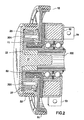
- Fig. 1 is a cross-sectional view of the two speed transmission.
- the two speed transmission 100 is used on a belt driven accessory drive of the type used on vehicle internal combustion engines. It may also be used in any application where a two speed transmission is needed, for example, for driving industrial equipment or as a transmission on a 2, 3 or 4 wheeled vehicle.
- the transmission and associated control system automatically control an accessory speed based on engine speed in order to optimize engine fuel efficiency and available output drive torque at the drive wheels.
- the transmission is very compact and can be mounted directly on an accessory, for example on a power steering pump, alternator or air conditioner compressor. In this arrangement the accessory is connected to an engine block.
- the two speed transmission 100 comprises planetary gears disposed on an input carrier.
- the transmission input shaft and output shaft are coaxial.
- An electromagnetic brake is used to control sun gear rotation and, thereby, output shaft speed.
- An endless power transmission belt is drivingly engaged between a driver pulley such as an engine crankshaft CR, see Fig. 12 , and a transmission input pulley 10.
- the belt may comprise a v-belt or multiple-ribbed belt, each known in the art.
- the belt may be replaced by a by a chain or toothed belt each know in the art.
- Input pulley 10 is connected to the input carrier using fasteners known in the art.
- the input carrier comprises input carrier portion 11 and input carrier portion 20 which is disposed opposite input carrier portion 11, planetary gear members 15, and input shaft 200.
- a plurality of shafts 21 interconnect between portion 11 and portion 20.
- Each planetary gear member 15 is journalled to a shaft 21.
- Input carrier portion 20 is connected to input shaft 200.
- Labyrinth seal 26 is connected to output pulley 30.
- O-ring seal 25 is disposed between shaft 19 and input carrier portion 11. Each seal is known in the art and prevents debris from entering the planetary gear set.
- Ring gear 17 and sun gear 18 each have a gear mesh engagement with planetary gears 15.
- Sun gear 18 is disposed on shaft 19.
- Ring gear 17 is disposed on the output pulley 30.
- Shaft 19 rotates concentrically about input shaft 200 and output shaft 31.
- Planetary gears 15, sun gear 18 and ring gear 17 comprise straight cut gears. Use of straight cut gears negates the need for thrust bearings which might otherwise be needed with helical type gears. This significantly reduces the cost of the planetary gear train.
- Brake 40 comprises a housing 52, an electromagnetic coil 41 and an axially moveable brake shoe 190 for frictional rotation stopping engagement.
- Brake shoe 190 of shaft 19 frictionally engages coil 41 when coil 41 is electrically activated, thereby stopping rotation of sun gear 18.
- Input shaft 200 is journalled to brake housing 52 on bearings 23, 24.
- Bearings 23, 24 comprise ball bearings known in the art and are used to provide a proper support for brake 40.
- Other bearings known in the art may also be used, for example, needle or cone bearings.
- Brake 40 is electromagnetically actuated to engage and stop rotation of portion 190 and thereby shaft 19 and sun gear 18 based upon an engine speed signal. Brake 40 is either engaged (shaft 19 stopped) or disengaged (shaft 19 rotates). Brake 40 is engaged at engine idle and disengaged for engine speeds above idle. Power is provided to the brake 40 coil by wires 410 from a vehicle electrical system, and may either be 12V or 42V or some other desired voltage.
- Retainer clips 230, 231 and 240 retain bearings 23, 24 in place on input shaft 200.
- the clips also keep input shaft 200 properly spatially located with respect to brake housing 52.
- Shaft 19 is journalled to input shaft 200 on sleeve bearing 50.
- a sleeve type bearing is sufficient for this service because the radial loads are minimal at idle when brake 40 is engaged, i.e., input shaft 200 is rotating and shaft 19 is locked up. At speeds greater than idle, brake 40 is disengaged and shaft 19 rotates in unison with input shaft 200 by operation of the one-way clutch 22, i.e., there is no differential rotation between shafts 19 and 200.
- Housing 52 can be mounted to an engine block or other mounting surface using known fasteners such as bolts, screws or studs engaged through bosses 53, 54.
- One-way clutch 22 is disposed between input shaft 200 and output shaft 31.
- One-way, or sprag, clutch 22 is of a type known in the art, for example, a model GFK 5904 available from Warner Electric/Formsprag.
- Planetary gears 15, belt bearing surface 33, bearing 50, and one-way clutch 22 are substantially coplanar in a radial direction with respect to an axis of rotation A-A. This arrangement has the benefit of minimizing or eliminating bending moments that might be imposed on the output portion of the transmission caused by a more axially staggered arrangement.
- End 32 of output shaft 31 allows an accessory to be directly connected to the output shaft 31.
- End 32 can be used with any form of coupling known in the art, for example, keyed, keyless or spliced.
- the accessory is directly connected to housing 52 using known fasteners, for example, bolts or screws, see Fig. 11 .
- the accessory can comprise an alternator, air conditioner compressor, power steering pump, fuel pump, oil pump or any other rotary accessory.
- the directly coupled accessory is driven at the same speed as the output pulley 30.
- Output pulley 30 engages an endless power transmission belt which transmits torque to other belt driven accessories in a belt drive system, see Fig. 12 .
- a power transmission belt B1 engaged with a driver such as a crankshaft pulley CR transmits torque to input pulley 10.
- the transmission output pulley 30 then transmits torque through a second endless belt B2 which is drivingly connected to other belt driven accessories.
- the transmission operates in one of two modes based upon engine speed.
- Brake status is a function of engine speed, i.e., the output pulley speed is determined in part by whether the brake is engaged or disengaged.
- the transmission ratio is the ratio of the transmission planetary gear set only and is independent of the pulley ratios, including the pulley ratio between the output pulley and the accessory pulley, as well as the ratio between the crankshaft CR pulley and the input pulley 10.
- a first operating mode brake 40 is engaged when the engine is started or operating at an idle speed.
- the brake is electrically engaged or disengaged by an engine speed signal provided by an engine control unit 500.
- Unit 500 may be formed as a computer system provided with known units including a CPU, a RAM, a ROM, a bi-directional communication bus, interface circuits (a signal conversion circuit and the like), and a memory.
- Unit 500 receives an engine speed signal from an sensor or instrument such as a tachometer 600, or other similar instrument for detecting rotational velocity known in the art such as a proximity detector.
- brake 40 When the engine is shut off, brake 40 is not engaged. When a key is inserted to start the engine, brake 40 is activated before the starter starts the engine. However, to ease the engine start, brake 40 can be activated slightly after the engine is running. In this case the one-way clutch drives the output shaft and the accessories are driven at a lower speed than required for idle, thereby minimizing the engine start power requirement. When the brake is disengaged the accessories are driven at a slower speed due to the pulley ratio between the output pulley 30 and an accessory pulley as described herein. The time delay between engine start and brake activation is approximately 0.5 to 1.0 seconds. After the time has elapsed brake 40 is engaged.
- the speed signal detected by an engine control unit 500 generates a control signal.
- the control signal activates the brake thereby stopping rotation of sun gear 18.
- the engine speed at which brake 40 is activated is selected based upon the nature of the engine and its desired operating characteristics.
- the engine idle speed is approximately 800 RPM.
- the transition speed at which the brake is engaged or disengaged is approximately 1200-1500 RPM so that the accessory speed does not drop significantly below a minimum desired speed at idle, thereby avoiding the situation where the accessory or accessories are driven too slowly, even if only momentarily.
- the second operating mode is when the engine is running at speeds greater than engine idle, for example at cruise or otherwise in excess of a pre-selected engine speed for example 1200-1500 RPM.
- brake 40 is disengaged. With the brake disengaged, shaft 19 is unlocked and sun gear 18 rotates in unison with the input carrier.
- One-way clutch 22 is engaged thereby driving output shaft 31 on a 1:1 basis with the input shaft 200.
- the transmission ratio is only a part of the overall system by which the belt driven accessory drive speed is determined.
- the rotational speed of each accessory is also individually determined in part by the diameter of the accessory pulley and its ratio with respect to the output pulley 30. Therefore, the final belt driven accessory speed for a given engine speed is a function of the driver pulley (crankshaft) diameter, input pulley 10 diameter, transmission ratio, output pulley diameter 30, and the accessory pulley diameter. Each of these variables are selected and combined to give the desired final drive ration and hence belt driven accessory speed.
- the final drive ratio determines the accessory speed for a given crankshaft (engine) speed.
- the inventive transmission can provide fuel savings on the order of up to approximately 5% compared to a comparable engine without the transmission.
- the inventive system at engine speeds greater than idle decreases the rotational speed of the accessories. This improves engine and vehicle performance, including improved acceleration times and increased power available at the drive wheels.
- the inventive system has the following operating characteristics.
- the final drive ratio in the 2.0L engine example for the alternator at engine idle is approximately 2.33 (1866 RPM/800 RPM).
- the final drive ratio for the alternator is approximately 1.48 (3705 RPM/2500 RPM).
- the inventive system imparts a final drive ratio for a belt driven accessory that is inversely related to engine speed.
- the inverse relationship of a pulley drive ratio to engine speed also applies to the accessory directly connected to and driven by the transmission, namely, the crankshaft pulley and the transmission input pulley.
- the inventive system is given full reign when the brake 40 is disengaged and one-way clutch 22 is locked.
- the input 10 and output 30 pulleys rotate in unison. This combined with the accessory pulleys decreases the accessory rotational speed as compared to a prior art system. Reducing the accessory speed in this manner significantly increases overall fuel efficiency of the engine. It also increases torque available to the drive wheels.
- the pulley ratios can be selected to accommodate any engine accessory drive configuration.
- the transmission ratio is also approximately 1.57.
- the idle speed in this example is approximately 650 RPM as compared to 800 RPM for the previous example.
- the final drive ratio in this example for the alternator at engine idle is approximately 3.26 (2121.6 RPM/650 RPM).
- the final drive ratio for the alternator is approximately 2.07 (3110 RPM/1500 RPM).
- the directly connected accessory speed at engine idle corresponds to the pulley ratio between the crankshaft pulley and the input pulley 10 as modified by the transmission ratio.
- the directly connected accessory speed corresponds to the pulley ratio between the crankshaft pulley and the input pulley 10.
- the planetary gears are not operable and all rotation of the output shaft is caused by the one-way clutch 22.
- the duty cycle for the transmission in the inventive system is approximately 5%, meaning the transmission is in operation (that is, brake engaged) approximately 5% of the time, basically when the engine is at idle.
- the duty cycle is dependent on the engine operating conditions and is preferably in the range of approximately 4% to 10% and may be as high as approximately 25% or 30%.
- the prior art systems have a reciprocal duty cycle ( ⁇ 95%) since they operate a transmission when the engine is operated at speeds greater than idle.
- a low duty cycle is desirable because it extends the operating life of the transmission.
- idle is used for ease of reference and is not intended to signify limiting the invention to particular engine speed. Idle speed can and does differ among various vehicles and engine types.
- the system allows multiple accessories to be driven at two different speeds for any range of engine speeds.
- This first available accessory speed being that of the accessory which is directly connected to the output shaft 31.
- the second accessory speed being that of the belt driven accessory as further determined by the transmission ratio and respective pulley ratio of the transmission output pulley 30 and a particular driven accessory pulley.
- the accessories can be selected and located in a belt drive system to optimize the beneficial effect of two available operational speeds.
- the air conditioner or alternator can be directly connected to the transmission output shaft (32) while other belt driven accessories, such as a power steering pump or water pump, are driven at a different speed by a second belt from the output pulley 30.
- the innovative compact design is realized by disposing the planetary gear train fully within the width (W) of the belt bearing portion 33 of the output pulley 30.
- Brake shoe 190 for the sun gear 18 is compactly disposed adjacent the input pulley 10.
- the overall thickness of the transmission is substantially a function of the width of the pulley 10, pulley 30 and the width of brake 40.
- brake 40 can be fully contained within a width (W2) of input pulley 10.
- the overall thickness of the transmission has a lower limit substantially bounded by the width of the input and output pulley in the closest possible proximity. For example, this can represent an overall end-to-end transmission thickness as small as approximately 45mm.
- the inventive transmission allows a significant increase in fuel efficiency while only requiring an extra clearance space on the order of approximately 30mm, and in certain cases less than 20mm is required based on the overall width of an output belt B2.
- Fig. 2 is a cross-sectional view of the two speed transmission.
- Input carrier portion 11 and input carrier portion 20 are connected together with members 27 by fasteners 201.
- Members 27 are circumferentially disposed about the input carrier, see Fig. 4 .
- Input pulley 10, input carrier portion 11, input carrier portion 20 and input shaft 200 comprise an input rotating assembly.
- planetary gears 15 are journalled to the input carrier shafts 21.
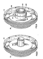
- Fig. 3 is a perspective view of the planetary gear carrier.
- Planetary gears 15 are disposed circumferentially about the carrier alternately interposed between members 27.
- Fasteners 201 connect portion 11 to members 27.
- Fig. 4 is a partial perspective view of the planetary gears on the carrier.
- Each planetary gear 15 is journalled to a shaft 21 on a bearing 210 known in the art, such as a needle bearing or sleeve bearing.
- the bearing selection is dependent on the service conditions.
- Fig. 5 is a partial perspective view of the planetary gear bearings and carrier sleeve bearing.
- Each planetary gear bearing 210 is disposed between a planetary gear 15 and a shaft 21.
- Carrier sleeve bearing 50 is disposed between input shaft 200 and output shaft 31.
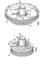
- Fig. 6 is a partial perspective view of the carrier and output pulley.
- the compact design of the transmission allows the planetary gear carrier to be fully contained within a width of the output pulley.
- Input shaft 200 comprises a bore 202 in which output shaft 31 is disposed.
- Fig. 7 is a partial perspective view of the carrier and output pulley and input pulley.
- Fasteners 12 attach input pulley 10 to input carrier portion 11.
- Input pulley 10 may also be attached to input carrier portion 11 by tack welding or any other suitable connecting means known in the art.
- Fig. 8 is a partial perspective view of the carrier brake shoe and output pulley.
- Brake shoe 190 comprises a radially extending surface which frictionally engages coil 41 upon activation of said coil. Engagement of shoe 190 with coil 41 stops rotation of the sun gear 18. Brake shoe 190 is substantially contained within a width of input pulley 10.
- Fig. 9 is a partial perspective view of the bearings and carrier brake shoe. Bearings 23, 24 support input shaft 200 on brake housing 52.
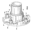
- Fig. 10 is a perspective view of the transmission with the coil.
- Brake 40 axially locates and supports input shaft 200 on bearings 23, 24.
- Bosses 53, 54 are used with fasteners to connect the transmission to a mounting surface.
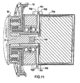
- Fig. 11 is a cross-sectional view of the two speed transmission connected to an alternator 700.
- Alternator 700 is directly coupled to the output shaft 31.
- Alternator 700 is simply used as an example as any other accessory may be directly connected to the transmission as well.
- Direct coupling is accomplished by use of splines 703 on shaft 31, although any form of shaft coupling suitable for the service and known in the art is acceptable.
- Tabs 702 extend from the transmission and alternator. Fasteners 701 connect tabs 702. Fasteners 701 comprise screws, bolts or studs for example. Alternator 700 is electrically connected to a vehicle electrical system in a manner known in the art.
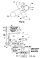
- Fig. 12 is a schematic of a belt driven accessory drive.
- Belt B1 is drivingly engaged between a crankshaft pulley CR and input pulley 10.
- Belt B2 is drivingly engaged between output pulley 30 and accessory pulleys A2 and A3.
- Belt B1 and B2 each comprise a multiple ribbed profile, see Fig. 2 .
- An accessory A1 is directly coupled to the transmission 100.
- Accessory A1 may comprise an alternator 700.
- a belt tensioner T imposes a tension on belt B2.
- Tensioner T may comprise any tensioner known in the art, including an asymmetric tensioner, Zed type, or linear tensioner.
- the asymmetric tensioner comprises a pulley pivotally mounted to a tensioner arm.
- the asymmetric tensioner comprises a damping mechanism that has a damping force which is greater in a first direction than in a second direction.
- either belt, B1 or B2 or both, used in the inventive system comprises a low modulus belt known in the art.
- the low modulus belt comprises a belt having a tensile cord comprising nylon 4.6 or nylon 6.6 or a combination of the two.
- An elastic modulus of the belt is in the range of approximately 1500 N/mm to approximately 3000 N/mm.
- a feature of the low modulus belt is that it can be installed on a belt drive system without a tensioner or moveable shaft accessory.
- the low modulus belt is simply installed using a belt installation tool known in the art. The tool is used to roll or laterally urge the belt over an edge of a transmission pulley or accessory pulley without the need to otherwise adjust the center location of the pulley shaft.
- the low modulus belt is particularly suitable for belt B1 since equipping the transmission in such a way that it would otherwise be movable to allow installation and adjustment of belt B1 might be more expensive than simply designing the transmission to be directly connected to an engine mounting surface such as an engine block. Further, adjusting the transmission shaft location with respect to the crankshaft would consume more assembly time as well.
- chains may be used in place of the belts.
- transmission 100 and one or all of the accessories may also be provided with adjustable mounting means known in the art which allows the shaft location to be adjusted during installation.
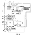
- Fig. 13 is a schematic of the inventive transmission used in a generator motor application.
- Automatic transmission (“A/T") 2 is disposed adjacent to the engine (“E/G”) 1.
- Motor generator 300 (“M/G”) serves as a motor and an electric generator.
- Engine crank shaft 3, and shaft 31 and shaft 200 of the M/G 300 are disposed in parallel with each other.
- M/G 300 is directly connected to transmission 100 as described elsewhere in this specification.
- Transmission 100 is mechanically disposed between the M/G 300 and the crank shaft 3 so that the rotational speed of shaft 200 is reduced and transmitted to crank shaft 3.
- Pulley CR is connected to the crank shaft 3.
- Pulley 10 is connected to transmission 100 as described in this specification.
- Belt B1 is set between pulley CR and pulley 10.
- Pulley 30 is directly connected to shaft 31 of the M/G 300.
- Pulley 10 is operatively connected to shaft 200 by the planetary gear set.
- Pump P for a power steering unit and a compressor A/C for an air conditioner are each an accessory included in the engine belt drive system.
- Pulleys A2 and A3 are secured to the respective ends of the rotational shafts of the pump P and the compressor A/C.
- a belt B2 is engaged among the pulleys 30, A2, and A3.
- the pulleys 30, A2, A3 and the belt B2 constitute a power transmission means for transmitting rotation of M/G 300 to the respective accessories.
- An inverter 400 is electrically connected to M/G 300 and arranged to vary the amount of electric energy to be supplied from a battery 800 to the M/G 300 to control the speed of M/G 300 when M/G 300 is used in a motor mode. Inverter 400 also performs control to store electric energy generated by M/G 300 to battery 800.
- M/G 300 is connected to an oil pump 194 for the A/T through electromagnetic clutch 191.
- An oil inlet pipe 192 is connected to the oil pump 194.
- An oil outlet pipe 193 is connected to the oil pump 194.
- Oil pimp 194 is connected to an engine lubrication system (not shown).
- the foregoing structure enables M/G 300 to operate the oil pump 194 by engaging electromagnetic clutch 191 while the engine is stopped. This is because the starting clutch (not shown) disposed in the A/T is arranged to be immediately engaged for driving the vehicle smoothly upon re-start of the engine.
- controller 500 transmits to inverter 400 a signal for controlling the engine running mode switching operation, ON-OFF control signals to the electromagnetic clutch 191 and ON-OFF control signals to the electromagnetic coil 41 of the transmission. Controller 500 also receives signals from various sensors disposed on the vehicle and on the engine that are indicative of a vehicle operating condition and/or of an engine operating condition.
- a signal indicating the speed of M/G 300 includes a signal indicating the speed of M/G 300, a signal for switching the engine running mode, a signal for switching the operation of the air conditioner, an engine status signal indicating, for example, the speed of the engine 1, a vehicle status signal (not shown) indicating the vehicle speed and the like, a wheel brake status signal, an engine throttle position signal, and a status signal of the A/T indicating the range selected by the shift lever.
- the brake status signal indicates the state of engagement of each wheel brake or all wheel brakes on the vehicle.
- the throttle position signal relates to the position of the throttle, which is indicative of the driver demand to the engine such as acceleration, deceleration, non-accelerating cruise or idle.
- Each signal may be either analogue or digital.
- controller 500 performs an operation for reading data from a memory 900 and a calculating operation to determine an engine first running mode (engine operating) or a second running mode (engine not operating). Then controller 500 transmits control signals to the transmission brake coil 41, the inverter 400, and electromagnetic clutch 191. Controller 500 may be formed as a computer system provided with known units including a CPU, a RAM, a ROM, a bi-directional communication bus, interface circuits (a signal conversion circuit and the like), and a memory 900.
- M/G 300 is operated to start the engine 1.
- M/G 300 acts as a power generator for storing electric energy in the battery 800.
- the controller 500 detects the speed of M/G 300.
- controller 500 causes inverter 400 to perform a switching operation such that a torque and speed required to start the engine 1 are realized. For example, if a signal for switching the air conditioner A/C has been turned ON at engine start, a higher torque is required compared with the OFF state of the A/C. Therefore, controller 500 applies to inverter 400 a switching control signal to allow M/G 300 to rotate at a higher torque with a greater speed.
- the switching control signal may be determined such that a variety of status signals of the engine 1, the A/T 2 and the vehicle are provided to the controller 500 and thereby collated with a map memory stored in the memory.
- the switching control signal may be determined by calculations performed by the processor unit (CPU) disposed in controller 500.
- controller 500 stops the engine 1 by transmitting a signal for interrupting fuel supply to the engine 1 for example to an electric fuel pump (not shown).
- the engine stop operation can be performed under a condition where, for example, the vehicle speed is zero, the brakes are partially or fully applied, and the shift lever is in the D or N setting. Thus, no power is transmitted between the pulley 10 and the engine 1.
- electromagnetic clutch 191 can be brought to a connected state to allow M/G 300 to operate the oil pump 194 while engine 1 is off. This is because the starting clutch (not shown) disposed in the A/T 2 is arranged to be immediately engaged for driving the vehicle smoothly upon re-starting of the engine.
- controller 500 applies to inverter 400 a switching control signal to rotate the M/G 300 at the speed and torque corresponding to the loads of the pump P for a power steering unit, the compressor A/C for the air conditioner and the oil pump 190 for the A/T 2. In this case brake 41 is OFF or disengaged.
- M/G 300 in motor mode cranks engine 1 when brake coil 41 is turned ON thereby stopping rotation of sun gear 18.
- Brake coil 41 is energized causing pulley 10 to rotate at a predetermined speed and torque.
- the rotational force of M/G 300 is transmitted at a decreased speed from the ring gear 17 to the carrier 11 and thereby to pulley 10 and thereby to crankshaft pulley CR.
- M/G 300 When the M/G 300 is used as an electric generator, and/or the accessories are operated while engine 1 is operating in a first running mode, brake coil 41 is turned OFF and one-way clutch 22 is in an engaged state.
- M/G 300 and the pulley 10 are rotationally connected with each other so that the rotations of pulley 10 are transmitted through clutch 22 to the M/G 300 via shaft 31.
- Transmission 100 is operating in part as a clutch to control transmission of torque to the engine, or to receive torque from the engine depending on the mode selected.
- Fig. 14 is a schematic of the inventive transmission in an alternate generator motor arrangement. Generally, the components and their relationship in this alternate embodiment are as described in Fig. 13 , with the differences described herein.
- M/G 300 is not directly attached to transmission 100.
- Transmission 100 has no directly connected accessory.
- M/G 300 is connected to transmission 100 by belt B2. Torque is transmitted to and from transmission 100 by belt B1 and B2 between engine 1, M/G 300 and the accessories.
- Transmission 100 is directly mounted to engine 1 using fasteners such as bolt or screws.
- This embodiment illustrates that the M/G can be connected, either directly or by belt, to either end of transmission output shaft 31.
- This provides alternate belt drive arrangements in which the inventive transmission can be successfully used.
- M/G 300 in motor mode cranks engine 1 through belt B2, transmission 100, and belt B1 when brake coil 41 is turned ON, thereby engaging the brake and stopping rotation of sun gear 18.
- Energizing brake coil 41 causes pulley 10 to rotate at a predetermined speed and torque.
- the rotational force of M/G 300 is transmitted at a decreased speed through belt B2, to pulley 30 to ring gear 17 to the carrier 11 and thereby to pulley 10 and thereby to crankshaft pulley CR through belt B1.
- accessories P and A/C are rotated while the M/G 300 is operating in motor mode during engine start as well.
- an accessory 1000 may be directly coupled to transmission 100 as described in Fig. 13 .
- Accessory 1000 may comprise a fuel pump, oil pump or any other accessory as may be required by an engine or vehicle.
- accessory 1000 is directly connected to transmission 100 and to shaft 31. Due to the unique arrangement of coaxial shafts 31, 200 of transmission 100, accessory 1000 is fully operable by M/G 300 along with the other accessories even when engine 1 is not operating and M/G 300 is in motor mode. Of course, accessory 1000 is also driven by engine 1 along with accessories P and A/C when engine 1 is operating and M/G 300 is operated as a generator.
Abstract
Description
- The invention relates to a two speed transmission and belt drive system, more particularly, to a vehicle engine belt drive system using a combination of accessory pulleys and a two speed transmission having an electromagnetic brake. The two speed transmission output pulley in combination with each accessory pulley drives engine accessories at a first speed substantially proportional to an engine speed at engine idle and proportionally less than the first engine speed for those engine speeds substantially greater than an engine idle speed. The transmission also provides a speed reducing unit disposed between an engine and a motor generator.
- Vehicle engines generally comprise certain accessories that are used in the operation of the engine and vehicle. Such accessories can include a power steering pump, an air conditioning compressor, an alternator, an oil pump, a fuel pump and so on. These accessories are generally driven by a serpentine belt. The serpentine belt engages a pulley on each accessory as well as on an engine crankshaft. The engine crankshaft provides the torque to drive the accessories.
- As the belt is driven by the crankshaft it is necessarily subject to engine speed variat ions during acceleration and deceleration of the vehicle. In other words the operating speed of the accessories is directly proportional to the speed of the engine. The variations in engine speed, particularly engine speeds greater than idle, result in inefficient operation of the accessories because each accessory must be designed to operate satisfactorily over the entire engine speed range. This necessarily means that the efficiency is less than optimum for most of the engine speed range. Therefore it is desirable to decouple some or all of the accessories from the engine crankshaft so they can be driven at a lower and narrower optimum speed range. Further, operating the accessories at relatively higher speeds places a greater load on the engine than if they are operated at a slower speed.
- Representative of the art is
US patent number 4,862,770 (1989) to Smith which discloses a two-speed gear box adapted to be mounted on the face of an automobile accessory, such as an automotive alternator to increase the speed of the alternator on demand. - The clutch assembly disclosed in Smith comprises a brake band encompassing an outer cylindrical surface. The brake band is operated with mechanical vacuum means which engage or disengage the brake band. Such a system can be adversely affected by loss of vacuum, for example by vacuum hose failure, or by contamination on the cylindrical surface between the brake band and the cylindrical surface.
- The prior art transmissions are designed to proportionately reduce the speed of the driven accessories as the engine speed increases above idle. This reduces the accessory power requirement. However, at idle the accessories are operated on a 1:1 basis with no speed reduction as compared to engine speeds above idle.
- In recent years, an automatic engine stopping and starting apparatus has been known for stopping an engine after a running vehicle has been stopped and restarting the engine if conditions for driving the vehicle have been satisfied again. The automatic engine stopping and starting apparatus is arranged such that fuel supply to the engine is interrupted while the vehicle is stopped, resulting in reduced fuel consumption.
- Representative of the art is
US patent number 6,048,288 (2000) to Tsujii et al. which discloses a system that operates a motor when a vehicle is stopped by providing a connection switching unit disposed between the drive shaft of the engine and a rotational shaft of the motor to enable/disable power transmission between the drive shaft of the engine and the rotational shaft of the motor, and a transmission controller that control a function of the connection switching unit, for enabling/disabling power transmission. When an auxiliary machine is operated by a motor while the engine is stopped, control is performed such that rotation of then rotational shaft of the motor is not transmitted to the drive shaft of the engine. The auxiliary machine is operated by the motor without operating the engine. - What is needed is a belt drive system that controls an accessory speed with respect to an engine speed by a combination of a two speed transmission ratio and output pulley and accessory pulley ratio. What is needed is a two speed transmission comprising an electromagnetic brake controlled with respect to an engine condition. What is needed is a two-speed transmission having coaxial input and dual outputs. What is needed is a motor generator system that has a speed reducing unit disposed between the engine and a motor generator. The present invention meets these needs.
- The features of the present invention that are known from
EP0 548955 have bean placed in the preamble ofclaim 1. - The primary aspect of the invention is to provide a belt drive system that controls an accessory speed with respect to an engine speed by a combination of a two speed transmission ratio and output pulley and accessory pulley ratio.
- Another aspect of the invention is to provide a two speed transmission comprising an electromagnetic brake controlled to an engine condition.
- Another aspect of the invention is to provide a two-speed transmission having coaxial input and dual outputs.
- Another aspect of the invention is to provide a motor generator system that has a speed reducing unit disposed between the engine and a motor generator.
- Other aspects of the invention will be pointed out or made obvious by the following description of the invention and the accompanying drawing.
- The invention comprises a two speed transmission as defined in
claim 1. The two speed transmission comprises a planetary gear train comprising an input pulley connected to an input carrier, and a sun gear and a ring gear. The input carrier also comprises a plurality of planetary gears disposed between the sun gear and the ring gear. The sun gear is engaged with an electromagnetic brake member. The ring gear is engaged with an output pulley. A one-way clutch is disposed between the input carrier and the output shaft. The brake member is engaged at engine idle and is disengaged at engine speeds above idle. When the brake member is engaged the sun gear does not rotate, thereby driving the ring gear and output pulley at a greater speed than the input pulley. An accessory pulley operates with the transmission output pulley resulting in an accessory speed that is proportional to an engine speed at idle. At engine speeds above idle the transmission is disengaged and the output pulley to accessory pulley ratio drives the belt driven accessory at a speed less then an engine speed. An accessory can also be directly connected to the output shaft in conjunction with the output pulley. The transmission can be used with a motor generator system by providing a speed reducing unit disposed between an engine and the motor generator. - The accompanying drawings, which are incorporated in and form a part of the specification, illustrate preferred embodiments of the present invention, and together with a description, serve to explain the principles of the invention.
-
Fig. 1 is a cross-sectional view of the two speed transmission. -
Fig. 2 is a cross-sectional view of the twp speed transmission. -
Fig. 3 is a perspective view of the planetary gear carrier. -
Fig. 4 is a partial perspective view of the planetary gears on the carrier. -
Fig. 5 is a partial perspective view of the planetary gear bearings and carrier bushings. -
Fig. 6 is a partial perspective view of the carrier and output pulley. -
Fig. 7 is a partial perspective view of the carrier and output pulley and input pulley. -
Fig. 8 is a partial perspective view of the carrier brake shoe and output pulley. -
Fig. 9 is a partial perspective view of the bearings and carrier brake shoe. -
Fig. 10 is a perspective view of the transmission with the coil. -
Fig. 11 is a cross-sectional view of the two speed transmission with an alternator connected to the transmission and coupled to the output shaft. -
Fig. 12 is a schematic of a belt driven accessory drive. -
Fig. 13 is a schematic of the inventive transmission used in a generator motor application. -
Fig. 14 is a schematic of the inventive transmission in an alternate generator motor arrangement. -
Fig. 1 is a cross-sectional view of the two speed transmission. The twospeed transmission 100 is used on a belt driven accessory drive of the type used on vehicle internal combustion engines. It may also be used in any application where a two speed transmission is needed, for example, for driving industrial equipment or as a transmission on a 2, 3 or 4 wheeled vehicle. - The transmission and associated control system automatically control an accessory speed based on engine speed in order to optimize engine fuel efficiency and available output drive torque at the drive wheels. The transmission is very compact and can be mounted directly on an accessory, for example on a power steering pump, alternator or air conditioner compressor. In this arrangement the accessory is connected to an engine block.
- The two
speed transmission 100 comprises planetary gears disposed on an input carrier. The transmission input shaft and output shaft are coaxial. An electromagnetic brake is used to control sun gear rotation and, thereby, output shaft speed. - An endless power transmission belt is drivingly engaged between a driver pulley such as an engine crankshaft CR, see
Fig. 12 , and atransmission input pulley 10. The belt may comprise a v-belt or multiple-ribbed belt, each known in the art. The belt may be replaced by a by a chain or toothed belt each know in the art. - Input
pulley 10 is connected to the input carrier using fasteners known in the art. The input carrier comprisesinput carrier portion 11 andinput carrier portion 20 which is disposed oppositeinput carrier portion 11,planetary gear members 15, andinput shaft 200. A plurality ofshafts 21 interconnect betweenportion 11 andportion 20. Eachplanetary gear member 15 is journalled to ashaft 21.Input carrier portion 20 is connected to inputshaft 200. -
Labyrinth seal 26 is connected tooutput pulley 30. O-ring seal 25 is disposed betweenshaft 19 andinput carrier portion 11. Each seal is known in the art and prevents debris from entering the planetary gear set. -
Ring gear 17 andsun gear 18 each have a gear mesh engagement withplanetary gears 15.Sun gear 18 is disposed onshaft 19.Ring gear 17 is disposed on theoutput pulley 30.Shaft 19 rotates concentrically aboutinput shaft 200 andoutput shaft 31. Planetary gears 15,sun gear 18 andring gear 17 comprise straight cut gears. Use of straight cut gears negates the need for thrust bearings which might otherwise be needed with helical type gears. This significantly reduces the cost of the planetary gear train. -
Brake 40 comprises ahousing 52, anelectromagnetic coil 41 and an axiallymoveable brake shoe 190 for frictional rotation stopping engagement.Brake shoe 190 ofshaft 19 frictionally engagescoil 41 whencoil 41 is electrically activated, thereby stopping rotation ofsun gear 18. -
Input shaft 200 is journalled to brakehousing 52 onbearings Bearings brake 40. Other bearings known in the art may also be used, for example, needle or cone bearings. -
Brake 40 is electromagnetically actuated to engage and stop rotation ofportion 190 and therebyshaft 19 andsun gear 18 based upon an engine speed signal.Brake 40 is either engaged (shaft 19 stopped) or disengaged (shaft 19 rotates).Brake 40 is engaged at engine idle and disengaged for engine speeds above idle. Power is provided to thebrake 40 coil bywires 410 from a vehicle electrical system, and may either be 12V or 42V or some other desired voltage. - Retainer clips 230, 231 and 240 retain
bearings input shaft 200. The clips also keepinput shaft 200 properly spatially located with respect to brakehousing 52. -
Shaft 19 is journalled to inputshaft 200 onsleeve bearing 50. A sleeve type bearing is sufficient for this service because the radial loads are minimal at idle whenbrake 40 is engaged, i.e.,input shaft 200 is rotating andshaft 19 is locked up. At speeds greater than idle,brake 40 is disengaged andshaft 19 rotates in unison withinput shaft 200 by operation of the one-way clutch 22, i.e., there is no differential rotation betweenshafts Housing 52 can be mounted to an engine block or other mounting surface using known fasteners such as bolts, screws or studs engaged throughbosses - One-way clutch 22 is disposed between
input shaft 200 andoutput shaft 31. One-way, or sprag, clutch 22 is of a type known in the art, for example, a model GFK 5904 available from Warner Electric/Formsprag. - Planetary gears 15,
belt bearing surface 33, bearing 50, and one-way clutch 22 are substantially coplanar in a radial direction with respect to an axis of rotation A-A. This arrangement has the benefit of minimizing or eliminating bending moments that might be imposed on the output portion of the transmission caused by a more axially staggered arrangement. -
End 32 ofoutput shaft 31 allows an accessory to be directly connected to theoutput shaft 31.End 32 can be used with any form of coupling known in the art, for example, keyed, keyless or spliced. The accessory is directly connected tohousing 52 using known fasteners, for example, bolts or screws, seeFig. 11 . The accessory can comprise an alternator, air conditioner compressor, power steering pump, fuel pump, oil pump or any other rotary accessory. The directly coupled accessory is driven at the same speed as theoutput pulley 30. -
Output pulley 30 engages an endless power transmission belt which transmits torque to other belt driven accessories in a belt drive system, seeFig. 12 . - In operation a power transmission belt B1 engaged with a driver such as a crankshaft pulley CR transmits torque to input
pulley 10. Thetransmission output pulley 30 then transmits torque through a second endless belt B2 which is drivingly connected to other belt driven accessories. - The transmission operates in one of two modes based upon engine speed. Brake status is a function of engine speed, i.e., the output pulley speed is determined in part by whether the brake is engaged or disengaged.
- When
brake 40 is engagedshaft 19 is held stationary with respect to the transmission housing, that is,shaft 19 does not rotate. Hence,sun gear 18 does not rotate. The input carrier drivesplanetary gears 15 onstationary sun gear 18. Rotation of theplanetary gears 15 in turn drivesring gear 17 which in turn drivesoutput pulley 30 andoutput shaft 31. The input/output pulley speed increase ratio in this mode is in the range of approximately 1.1 to 3.0 depending upon the relative diameters of the sun gear and ring gear. The preferred transmission ratio is in the range of approximately 1.3 to 1.8, although ratios outside this range are available for use if required by a particular system. The transmission ratio is the ratio of the transmission planetary gear set only and is independent of the pulley ratios, including the pulley ratio between the output pulley and the accessory pulley, as well as the ratio between the crankshaft CR pulley and theinput pulley 10. - In a first
operating mode brake 40 is engaged when the engine is started or operating at an idle speed. The brake is electrically engaged or disengaged by an engine speed signal provided by anengine control unit 500.Unit 500 may be formed as a computer system provided with known units including a CPU, a RAM, a ROM, a bi-directional communication bus, interface circuits (a signal conversion circuit and the like), and a memory.Unit 500 receives an engine speed signal from an sensor or instrument such as atachometer 600, or other similar instrument for detecting rotational velocity known in the art such as a proximity detector. - When the engine is shut off,
brake 40 is not engaged. When a key is inserted to start the engine,brake 40 is activated before the starter starts the engine. However, to ease the engine start, brake 40 can be activated slightly after the engine is running. In this case the one-way clutch drives the output shaft and the accessories are driven at a lower speed than required for idle, thereby minimizing the engine start power requirement. When the brake is disengaged the accessories are driven at a slower speed due to the pulley ratio between theoutput pulley 30 and an accessory pulley as described herein. The time delay between engine start and brake activation is approximately 0.5 to 1.0 seconds. After the time has elapsedbrake 40 is engaged. More particularly, at engine start, or, as the engine speed slows below a desired level, for example approximately 1200-1500 RPM, the speed signal detected by anengine control unit 500 generates a control signal. The control signal activates the brake thereby stopping rotation ofsun gear 18. As noted, this results in theoutput shaft 30 being driven through the planetary gears at a greater rotational speed than the driveninput shaft 10. Of course, the engine speed at whichbrake 40 is activated is selected based upon the nature of the engine and its desired operating characteristics. - In this description the engine idle speed is approximately 800 RPM. The transition speed at which the brake is engaged or disengaged is approximately 1200-1500 RPM so that the accessory speed does not drop significantly below a minimum desired speed at idle, thereby avoiding the situation where the accessory or accessories are driven too slowly, even if only momentarily.
- The second operating mode is when the engine is running at speeds greater than engine idle, for example at cruise or otherwise in excess of a pre-selected engine speed for example 1200-1500 RPM. Once the selected speed is detected by
unit 500,brake 40 is disengaged. With the brake disengaged,shaft 19 is unlocked andsun gear 18 rotates in unison with the input carrier. One-way clutch 22 is engaged thereby drivingoutput shaft 31 on a 1:1 basis with theinput shaft 200. - However, the transmission ratio is only a part of the overall system by which the belt driven accessory drive speed is determined. The rotational speed of each accessory is also individually determined in part by the diameter of the accessory pulley and its ratio with respect to the
output pulley 30. Therefore, the final belt driven accessory speed for a given engine speed is a function of the driver pulley (crankshaft) diameter, inputpulley 10 diameter, transmission ratio,output pulley diameter 30, and the accessory pulley diameter. Each of these variables are selected and combined to give the desired final drive ration and hence belt driven accessory speed. The final drive ratio determines the accessory speed for a given crankshaft (engine) speed. - In an exemplary accessory drive system, it is estimated that the inventive transmission can provide fuel savings on the order of up to approximately 5% compared to a comparable engine without the transmission. The inventive system at engine speeds greater than idle decreases the rotational speed of the accessories. This improves engine and vehicle performance, including improved acceleration times and increased power available at the drive wheels.
- In an exemplary system using a 2.0L engine, the inventive system has the following operating characteristics.
-
Pulley Diameters (mm) Accessory Speeds (RPM)- "Idle" Accessory Speeds (RPM) - "Off Idle" Original Drive Two Speed Module Original Drive Two Speed Module Original Drive Two Speed Module Crank 134.01 111.98 800 800 2500 2500 AC 146.01 N/A 734 734 2295 1458 PS 139.51 138.03 767 767 2402 1536 Alt 56.86 56.86 1866 1866 5833 3705 WP 107.50 106.38 998 998 3118 1981 Input N/A 192.00 N/A 467 N/A 1458 Output N/A 144.50 N/A 734 N/A 1458 - In the first column the diameter in mm is given for each pulley as used on an original drive and on a drive system using the two speed transmission (two speed module). The nomenclature is as follows: "Crank" - crankshaft, "AC" - air conditioner, "PS" - power steering, "Alt" - alternator, "WP" - water pump. In this example system the air conditioner (AC) is directly connected to the
output shaft 31 of the transmission, however, this is not intended to be limiting since any of the accessories may be directly connected tooutput shaft 31. At an engine speed referred to as "idle" for ease of reference, the two speed transmission is engaged, that is,brake 40 is engaged. "Idle" in this example is arbitrarily set at approximately 800 RPM. The transmission ratio is approximately 1.57. At idle the speed of the accessories as driven by the two speed transmission is the same as a proportional "original drive". An "original drive" is a prior art drive directly engaged with the crankshaft without a two speed transmission. - At an engine speed greater than idle, in this example 2500 RPM,
brake 40 is disengaged. Therefore, one-way clutch 22 is operational resulting ininput pulley 10 andoutput 30 pulley rotating in unison. Inputpulley 10 andoutput pulley 30 each rotate at 1458 RPM. However, due to the pulley diameter for each accessory, one can see that each accessory rotates at a relatively slower speed as compared to the original prior art system. In this and the following example at idle, the pulley diameters are selected so that the respective pulley ratio between theoutput pulley 30 and each accessory pulley effectively negates the 1.57x relative speed increase caused by the transmission whenbrake 40 is engaged. - The final drive ratio in the 2.0L engine example for the alternator at engine idle is approximately 2.33 (1866 RPM/800 RPM). At the "off idle" engine speed the final drive ratio for the alternator is approximately 1.48 (3705 RPM/2500 RPM). The inventive system imparts a final drive ratio for a belt driven accessory that is inversely related to engine speed. The inverse relationship of a pulley drive ratio to engine speed also applies to the accessory directly connected to and driven by the transmission, namely, the crankshaft pulley and the transmission input pulley.
- At engine speeds greater than idle, the inventive system is given full reign when the
brake 40 is disengaged and one-way clutch 22 is locked. Theinput 10 andoutput 30 pulleys rotate in unison. This combined with the accessory pulleys decreases the accessory rotational speed as compared to a prior art system. Reducing the accessory speed in this manner significantly increases overall fuel efficiency of the engine. It also increases torque available to the drive wheels. Of course, the pulley ratios can be selected to accommodate any engine accessory drive configuration. - In another example, a 5.3 L engine system is illustrated.
-
Pulley Diameters (mm) Accessory Speeds (RPM)- "Idle" Accessory Speeds (RPM) - "Off Idle" Original Drive Two Speed Module Original Drive Two Speed Module Original Drive Two Speed Module Crank 193.57 193.57 650 650 1500 1500 AC 111.9 N/A 1124.5 1124.5 2595 1648 PS 163.6 187.19 769 769 1775 1127 Alt 59.31 67.8 2121.6 2121.6 4896 3110 WP 150.8 172.46 834.6 834.6 1926 1223 Input N/A 176.13 N/A 714.4 N/A 1648 Output N/A 128 N/A 1124.5 N/A 1648 - In this example, the transmission ratio is also approximately 1.57. The idle speed in this example is approximately 650 RPM as compared to 800 RPM for the previous example. The final drive ratio in this example for the alternator at engine idle is approximately 3.26 (2121.6 RPM/650 RPM). At the "off idle" engine speed the final drive ratio for the alternator is approximately 2.07 (3110 RPM/1500 RPM).
- In each example, with respect to the A/C which is directly connected to
output shaft 31, the directly connected accessory speed at engine idle corresponds to the pulley ratio between the crankshaft pulley and theinput pulley 10 as modified by the transmission ratio. At engine speeds in excess of engine idle the directly connected accessory speed corresponds to the pulley ratio between the crankshaft pulley and theinput pulley 10. At engine speeds above idle there is no additional effect due to the transmission ratio since the planetary gears are not operable and all rotation of the output shaft is caused by the one-way clutch 22. - The duty cycle for the transmission in the inventive system is approximately 5%, meaning the transmission is in operation (that is, brake engaged) approximately 5% of the time, basically when the engine is at idle. The duty cycle is dependent on the engine operating conditions and is preferably in the range of approximately 4% to 10% and may be as high as approximately 25% or 30%. On the other hand the prior art systems have a reciprocal duty cycle (∼95%) since they operate a transmission when the engine is operated at speeds greater than idle. A low duty cycle is desirable because it extends the operating life of the transmission. It should again be understood that the term idle is used for ease of reference and is not intended to signify limiting the invention to particular engine speed. Idle speed can and does differ among various vehicles and engine types.
- The system allows multiple accessories to be driven at two different speeds for any range of engine speeds. This first available accessory speed being that of the accessory which is directly connected to the
output shaft 31. The second accessory speed being that of the belt driven accessory as further determined by the transmission ratio and respective pulley ratio of thetransmission output pulley 30 and a particular driven accessory pulley. - The accessories can be selected and located in a belt drive system to optimize the beneficial effect of two available operational speeds. For example, the air conditioner or alternator can be directly connected to the transmission output shaft (32) while other belt driven accessories, such as a power steering pump or water pump, are driven at a different speed by a second belt from the
output pulley 30. - The innovative compact design is realized by disposing the planetary gear train fully within the width (W) of the
belt bearing portion 33 of theoutput pulley 30.Brake shoe 190 for thesun gear 18 is compactly disposed adjacent theinput pulley 10. Hence the overall thickness of the transmission is substantially a function of the width of thepulley 10,pulley 30 and the width ofbrake 40. Depending upon electrical service requirements, conditions, brake 40 can be fully contained within a width (W2) ofinput pulley 10. Hence, the overall thickness of the transmission has a lower limit substantially bounded by the width of the input and output pulley in the closest possible proximity. For example, this can represent an overall end-to-end transmission thickness as small as approximately 45mm. Assuming that at least a single belt width is a given in front end accessory drives, the inventive transmission allows a significant increase in fuel efficiency while only requiring an extra clearance space on the order of approximately 30mm, and in certain cases less than 20mm is required based on the overall width of an output belt B2. -
Fig. 2 is a cross-sectional view of the two speed transmission.Input carrier portion 11 andinput carrier portion 20 are connected together withmembers 27 byfasteners 201.Members 27 are circumferentially disposed about the input carrier, seeFig. 4 . Inputpulley 10,input carrier portion 11,input carrier portion 20 andinput shaft 200 comprise an input rotating assembly. As described inFig. 1 planetary gears 15 are journalled to theinput carrier shafts 21. Whenbrake 40 is disengaged, one-way clutch 22 is engaged and thereby drivesoutput shaft 31. Whenbrake 40 is engaged one-way clutch 22 is disengaged sinceoutput shaft 31 is rotating as a speed greater than the speed ofinput shaft 200. -
Fig. 3 is a perspective view of the planetary gear carrier.Planetary gears 15 are disposed circumferentially about the carrier alternately interposed betweenmembers 27.Fasteners 201connect portion 11 tomembers 27. -
Fig. 4 is a partial perspective view of the planetary gears on the carrier. Eachplanetary gear 15 is journalled to ashaft 21 on abearing 210 known in the art, such as a needle bearing or sleeve bearing. The bearing selection is dependent on the service conditions. -
Fig. 5 is a partial perspective view of the planetary gear bearings and carrier sleeve bearing. Each planetary gear bearing 210 is disposed between aplanetary gear 15 and ashaft 21.Carrier sleeve bearing 50 is disposed betweeninput shaft 200 andoutput shaft 31. -
Fig. 6 is a partial perspective view of the carrier and output pulley. The compact design of the transmission allows the planetary gear carrier to be fully contained within a width of the output pulley.Input shaft 200 comprises abore 202 in whichoutput shaft 31 is disposed. -
Fig. 7 is a partial perspective view of the carrier and output pulley and input pulley.Fasteners 12 attachinput pulley 10 to inputcarrier portion 11. Inputpulley 10 may also be attached to inputcarrier portion 11 by tack welding or any other suitable connecting means known in the art. -
Fig. 8 is a partial perspective view of the carrier brake shoe and output pulley.Brake shoe 190 comprises a radially extending surface which frictionally engagescoil 41 upon activation of said coil. Engagement ofshoe 190 withcoil 41 stops rotation of thesun gear 18.Brake shoe 190 is substantially contained within a width ofinput pulley 10. -
Fig. 9 is a partial perspective view of the bearings and carrier brake shoe.Bearings support input shaft 200 onbrake housing 52. -
Fig. 10 is a perspective view of the transmission with the coil.Brake 40 axially locates and supportsinput shaft 200 onbearings Bosses -
Fig. 11 is a cross-sectional view of the two speed transmission connected to analternator 700.Alternator 700 is directly coupled to theoutput shaft 31.Alternator 700 is simply used as an example as any other accessory may be directly connected to the transmission as well. Direct coupling is accomplished by use ofsplines 703 onshaft 31, although any form of shaft coupling suitable for the service and known in the art is acceptable. -
Tabs 702 extend from the transmission and alternator.Fasteners 701 connecttabs 702.Fasteners 701 comprise screws, bolts or studs for example.Alternator 700 is electrically connected to a vehicle electrical system in a manner known in the art. -
Fig. 12 is a schematic of a belt driven accessory drive. Belt B1 is drivingly engaged between a crankshaft pulley CR and inputpulley 10. Belt B2 is drivingly engaged betweenoutput pulley 30 and accessory pulleys A2 and A3. Belt B1 and B2 each comprise a multiple ribbed profile, seeFig. 2 . An accessory A1 is directly coupled to thetransmission 100. Accessory A1 may comprise analternator 700. A belt tensioner T imposes a tension on belt B2. Tensioner T may comprise any tensioner known in the art, including an asymmetric tensioner, Zed type, or linear tensioner. - The asymmetric tensioner comprises a pulley pivotally mounted to a tensioner arm. The asymmetric tensioner comprises a damping mechanism that has a damping force which is greater in a first direction than in a second direction.
- In an alternate embodiment, either belt, B1 or B2 or both, used in the inventive system comprises a low modulus belt known in the art. The low modulus belt comprises a belt having a tensile cord comprising nylon 4.6 or nylon 6.6 or a combination of the two. An elastic modulus of the belt is in the range of approximately 1500 N/mm to approximately 3000 N/mm. A feature of the low modulus belt is that it can be installed on a belt drive system without a tensioner or moveable shaft accessory. The low modulus belt is simply installed using a belt installation tool known in the art. The tool is used to roll or laterally urge the belt over an edge of a transmission pulley or accessory pulley without the need to otherwise adjust the center location of the pulley shaft. The low modulus belt is particularly suitable for belt B1 since equipping the transmission in such a way that it would otherwise be movable to allow installation and adjustment of belt B1 might be more expensive than simply designing the transmission to be directly connected to an engine mounting surface such as an engine block. Further, adjusting the transmission shaft location with respect to the crankshaft would consume more assembly time as well.
- In yet another embodiment chains may be used in place of the belts.
- Of course,
transmission 100 and one or all of the accessories may also be provided with adjustable mounting means known in the art which allows the shaft location to be adjusted during installation. -
Fig. 13 is a schematic of the inventive transmission used in a generator motor application. Automatic transmission ("A/T") 2 is disposed adjacent to the engine ("E/G") 1. Motor generator 300 ("M/G") serves as a motor and an electric generator. Engine crankshaft 3, andshaft 31 andshaft 200 of the M/G 300 are disposed in parallel with each other. M/G 300 is directly connected totransmission 100 as described elsewhere in this specification.Transmission 100 is mechanically disposed between the M/G 300 and thecrank shaft 3 so that the rotational speed ofshaft 200 is reduced and transmitted to crankshaft 3. Pulley CR is connected to the crankshaft 3.Pulley 10 is connected totransmission 100 as described in this specification. Belt B1 is set between pulley CR andpulley 10.Pulley 30 is directly connected toshaft 31 of the M/G 300.Pulley 10 is operatively connected toshaft 200 by the planetary gear set. - Pump P for a power steering unit and a compressor A/C for an air conditioner are each an accessory included in the engine belt drive system. Pulleys A2 and A3 are secured to the respective ends of the rotational shafts of the pump P and the compressor A/C. A belt B2 is engaged among the
pulleys 30, A2, and A3. Thepulleys 30, A2, A3 and the belt B2 constitute a power transmission means for transmitting rotation of M/G 300 to the respective accessories. - An
inverter 400 is electrically connected to M/G 300 and arranged to vary the amount of electric energy to be supplied from abattery 800 to the M/G 300 to control the speed of M/G 300 when M/G 300 is used in a motor mode.Inverter 400 also performs control to store electric energy generated by M/G 300 tobattery 800. - M/
G 300 is connected to anoil pump 194 for the A/T throughelectromagnetic clutch 191. Anoil inlet pipe 192 is connected to theoil pump 194. Anoil outlet pipe 193 is connected to theoil pump 194.Oil pimp 194 is connected to an engine lubrication system (not shown). The foregoing structure enables M/G 300 to operate theoil pump 194 by engagingelectromagnetic clutch 191 while the engine is stopped. This is because the starting clutch (not shown) disposed in the A/T is arranged to be immediately engaged for driving the vehicle smoothly upon re-start of the engine. - Referring again to
Fig. 13 ,controller 500 transmits to inverter 400 a signal for controlling the engine running mode switching operation, ON-OFF control signals to theelectromagnetic clutch 191 and ON-OFF control signals to theelectromagnetic coil 41 of the transmission.Controller 500 also receives signals from various sensors disposed on the vehicle and on the engine that are indicative of a vehicle operating condition and/or of an engine operating condition. These include a signal indicating the speed of M/G 300, a signal for switching the engine running mode, a signal for switching the operation of the air conditioner, an engine status signal indicating, for example, the speed of theengine 1, a vehicle status signal (not shown) indicating the vehicle speed and the like, a wheel brake status signal, an engine throttle position signal, and a status signal of the A/T indicating the range selected by the shift lever. The brake status signal indicates the state of engagement of each wheel brake or all wheel brakes on the vehicle. The throttle position signal relates to the position of the throttle, which is indicative of the driver demand to the engine such as acceleration, deceleration, non-accelerating cruise or idle. Each signal may be either analogue or digital. - In accordance with information indicated by the above-mentioned
signals controller 500 performs an operation for reading data from amemory 900 and a calculating operation to determine an engine first running mode (engine operating) or a second running mode (engine not operating). Thencontroller 500 transmits control signals to thetransmission brake coil 41, theinverter 400, andelectromagnetic clutch 191.Controller 500 may be formed as a computer system provided with known units including a CPU, a RAM, a ROM, a bi-directional communication bus, interface circuits (a signal conversion circuit and the like), and amemory 900. - The operation will now be described. Initially, M/
G 300 is operated to start theengine 1. After starting theengine 1, M/G 300 acts as a power generator for storing electric energy in thebattery 800. When the engine is started, thecontroller 500 detects the speed of M/G 300. Moreover,controller 500 causesinverter 400 to perform a switching operation such that a torque and speed required to start theengine 1 are realized. For example, if a signal for switching the air conditioner A/C has been turned ON at engine start, a higher torque is required compared with the OFF state of the A/C. Therefore,controller 500 applies to inverter 400 a switching control signal to allow M/G 300 to rotate at a higher torque with a greater speed. - The switching control signal may be determined such that a variety of status signals of the
engine 1, the A/T 2 and the vehicle are provided to thecontroller 500 and thereby collated with a map memory stored in the memory. Alternatively, the switching control signal may be determined by calculations performed by the processor unit (CPU) disposed incontroller 500. - When an engine stop signal is turned ON
controller 500 stops theengine 1 by transmitting a signal for interrupting fuel supply to theengine 1 for example to an electric fuel pump (not shown). The engine stop operation can be performed under a condition where, for example, the vehicle speed is zero, the brakes are partially or fully applied, and the shift lever is in the D or N setting. Thus, no power is transmitted between thepulley 10 and theengine 1. In this state,electromagnetic clutch 191 can be brought to a connected state to allow M/G 300 to operate theoil pump 194 whileengine 1 is off. This is because the starting clutch (not shown) disposed in the A/T 2 is arranged to be immediately engaged for driving the vehicle smoothly upon re-starting of the engine. - In the case where the air conditioner and the power steering are required to be operated even if the
engine 1 is stopped,controller 500 applies to inverter 400 a switching control signal to rotate the M/G 300 at the speed and torque corresponding to the loads of the pump P for a power steering unit, the compressor A/C for the air conditioner and theoil pump 190 for the A/T 2. In thiscase brake 41 is OFF or disengaged. - When the
engine 1 is re-started from a state where the vehicle is stopped, M/G 300 in motor mode cranksengine 1 whenbrake coil 41 is turned ON thereby stopping rotation ofsun gear 18.Brake coil 41 is energized causingpulley 10 to rotate at a predetermined speed and torque. Thus, the rotational force of M/G 300 is transmitted at a decreased speed from thering gear 17 to thecarrier 11 and thereby topulley 10 and thereby to crankshaft pulley CR. - When the M/
G 300 is used as an electric generator, and/or the accessories are operated whileengine 1 is operating in a first running mode,brake coil 41 is turned OFF and one-way clutch 22 is in an engaged state. Thus, M/G 300 and thepulley 10 are rotationally connected with each other so that the rotations ofpulley 10 are transmitted through clutch 22 to the M/G 300 viashaft 31. - When the pump P and the compressor A/C are operated by M/
G 300 in motor mode whileengine 1 is stopped,brake coil 41 is turned OFF. In this second runningmode engine 1 is stopped and pinion gears 15 andsun gear 18 rotate freely.Carrier 11 andpulley 10 do not rotate because they are engaged with belt B1 which is engaged with stopped crankshaft pulley CR. Sincebrake 41 is OFF,sun gear 18 rotates in a direction opposite that ofring gear 17 andpulley 30. In effect, this configuration acts as though thetransmission 100 in placed in a 'neutral' gear thereby preventing transmission of torque frompulley 30 topulley 10. -
Transmission 100 is operating in part as a clutch to control transmission of torque to the engine, or to receive torque from the engine depending on the mode selected. -
Fig. 14 is a schematic of the inventive transmission in an alternate generator motor arrangement. Generally, the components and their relationship in this alternate embodiment are as described inFig. 13 , with the differences described herein. - In this alternate embodiment M/
G 300 is not directly attached totransmission 100.Transmission 100 has no directly connected accessory. M/G 300 is connected totransmission 100 by belt B2. Torque is transmitted to and fromtransmission 100 by belt B1 and B2 betweenengine 1, M/G 300 and the accessories.Transmission 100 is directly mounted toengine 1 using fasteners such as bolt or screws. - This embodiment illustrates that the M/G can be connected, either directly or by belt, to either end of
transmission output shaft 31. This provides alternate belt drive arrangements in which the inventive transmission can be successfully used. - In operation, when the
engine 1 is re-started from a state where the vehicle is stopped at a stop light for example, M/G 300 in motor mode cranksengine 1 through belt B2,transmission 100, and belt B1 whenbrake coil 41 is turned ON, thereby engaging the brake and stopping rotation ofsun gear 18. Energizingbrake coil 41 causespulley 10 to rotate at a predetermined speed and torque. Thus, the rotational force of M/G 300 is transmitted at a decreased speed through belt B2, topulley 30 to ringgear 17 to thecarrier 11 and thereby topulley 10 and thereby to crankshaft pulley CR through belt B1. Due to the configuration of belt B2, accessories P and A/C are rotated while the M/G 300 is operating in motor mode during engine start as well. - When the M/
G 300 is used as an electric generator, and/or the accessories are operated whileengine 1 is operating in a first running mode,brake coil 41 is turned OFF and one-way clutch 22 is in an engaged state. Thus,pulley 30 andpulley 10 are directly connected with each other so that the rotations ofpulley 10 are transmitted topulley 30 and thereby to the accessories P, A/C and M/G 300 through belt B2. - When the pump P and the compressor A/C are operated by M/
G 300, with M/G 300 in motor mode whileengine 1 is stopped,brake coil 41 is turned OFF. In this second runningmode engine 1 is stopped and pinion gears 15 andsun gear 18 rotate freely.Carrier 11 andpulley 10 do not rotate because they are engaged with belt B1 which is engaged with stopped crankshaft pulley CR. Sincebrake 41 is OFF,sun gear 18 rotates in a direction opposite that ofring gear 17 andpulley 30, thereby allowing M/G 300 to operate accessories P and A/C through belt B2 without also startingengine 1. - In yet another alternate embodiment, an
accessory 1000 may be directly coupled totransmission 100 as described inFig. 13 .Accessory 1000 may comprise a fuel pump, oil pump or any other accessory as may be required by an engine or vehicle. In thisembodiment accessory 1000 is directly connected totransmission 100 and toshaft 31. Due to the unique arrangement ofcoaxial shafts transmission 100,accessory 1000 is fully operable by M/G 300 along with the other accessories even whenengine 1 is not operating and M/G 300 is in motor mode. Of course,accessory 1000 is also driven byengine 1 along with accessories P and A/C whenengine 1 is operating and M/G 300 is operated as a generator.
Claims (7)
- A two speed transmission (100) comprising:a planetary gear train (15) comprising an input member (11) connected to an input carrier (20), the input carrier (20) connected to an input shaft (200);a sun gear (18), a ring gear (17) and a brake (40) having a brake member (190),the input carrier (20) comprising a plurality of planetary members (15) each in meshing engagement with the sun gear (18) and the ring gear (17);the sun gear (18) being connected to the brake member (190) of the brake (40);the ring gear (17) being connected to an output member (30); anda one-way clutch (22) operably disposed between the input shaft (200) and the output member (30); characterised in that:the input member comprises a pulley (10);the brake (40) is electromagnetic; andthe brake member (190) is substantially disposed within a width of the input member pulley (10).
- The two speed transmission (100) as in claim 1, wherein the output member comprises a pulley (30).
- The two speed transmission (100) as in claim 2 wherein the planetary gear train (15) is substantially disposed within width of the output member pulley (50).
- The two speed transmission (100) as in claim 2, wherein the output member (30) further comprises means (32) for direct connection to an accessory.
- The two speed transmission (100) as in claim J, wherein the input member (11) and the output member (10) are coaxial.
- The two speed transmission (100) as in claim 1 further comprising:a bearing (23,24) disposed between the brake (40) and the input shaft (200); anda bearing (50) disposed between the sun gear (18) and the input shaft (200).
- A two speed transmission (100) according to claim 1, wherein
the input member (11) and the output member (30) are coaxially disposed;
the planetary gear (15) members disposed between the input member (11) and the output member (30); and
the one-way clutch (22) is engaged when the electromagnetic brake (40) is disengaged.
Applications Claiming Priority (2)
| Application Number | Priority Date | Filing Date | Title |
|---|---|---|---|
| US10/756,079 US7316628B2 (en) | 2004-01-13 | 2004-01-13 | Two speed transmission and belt drive system |
| PCT/US2004/023002 WO2005071819A1 (en) | 2004-01-13 | 2004-07-16 | Two speed transmission and belt drive system |
Publications (2)
| Publication Number | Publication Date |
|---|---|
| EP1711992A1 EP1711992A1 (en) | 2006-10-18 |
| EP1711992B1 true EP1711992B1 (en) | 2009-11-18 |
Family
ID=34739750
Family Applications (1)
| Application Number | Title | Priority Date | Filing Date |
|---|---|---|---|
| EP04778476A Not-in-force EP1711992B1 (en) | 2004-01-13 | 2004-07-16 | Two speed transmission and belt drive system |
Country Status (12)
| Country | Link |
|---|---|
| US (2) | US7316628B2 (en) |
| EP (1) | EP1711992B1 (en) |
| JP (3) | JP4649417B2 (en) |
| KR (2) | KR100805178B1 (en) |
| CN (2) | CN100471714C (en) |
| AT (1) | ATE449452T1 (en) |
| AU (1) | AU2004314557B2 (en) |
| BR (1) | BRPI0418398B1 (en) |
| CA (2) | CA2697890C (en) |
| DE (1) | DE602004024241D1 (en) |
| RU (1) | RU2335839C2 (en) |
| WO (1) | WO2005071819A1 (en) |
Families Citing this family (99)
| Publication number | Priority date | Publication date | Assignee | Title |
|---|---|---|---|---|
| US7011600B2 (en) | 2003-02-28 | 2006-03-14 | Fallbrook Technologies Inc. | Continuously variable transmission |
| US7086981B2 (en) * | 2004-02-18 | 2006-08-08 | The Gates Corporation | Transmission and constant speed accessory drive |
| ATE550573T1 (en) | 2004-10-05 | 2012-04-15 | Fallbrook Technologies Inc | CONTINUOUSLY ADJUSTABLE GEARBOX |
| FR2882699B1 (en) * | 2005-03-01 | 2008-10-31 | Peugeot Citroen Automobiles Sa | METHOD OF TAKING A VEHICLE UP AND DOWN AND LOADING |
| ITTO20050288A1 (en) * | 2005-04-29 | 2006-10-30 | Mauro Palitto | START-STOP CONTROL UNIT FOR A MOTOR VEHICLE |
| CN102425649B (en) | 2005-10-28 | 2014-09-24 | 福博科知识产权有限责任公司 | Electromotive drives |
| DK1954959T3 (en) | 2005-11-22 | 2013-08-26 | Fallbrook Ip Co Llc | Continuously variable transmission |
| DE202005018560U1 (en) * | 2005-11-25 | 2006-02-23 | Power Hybrid Deutschland Gmbh | Conversion kit for saving fuel in passenger cars |
| CN101454596B (en) | 2005-12-09 | 2011-06-29 | 瀑溪技术公司 | Continuously variable transmission |
| US20070137197A1 (en) * | 2005-12-21 | 2007-06-21 | David Turner | Engine supercharging system |
| EP1811202A1 (en) | 2005-12-30 | 2007-07-25 | Fallbrook Technologies, Inc. | A continuously variable gear transmission |
| US7882762B2 (en) | 2006-01-30 | 2011-02-08 | Fallbrook Technologies Inc. | System for manipulating a continuously variable transmission |
| WO2007106874A2 (en) | 2006-03-14 | 2007-09-20 | Autocraft Industries, Inc. | Improved wheelchair |
| US20070261902A1 (en) * | 2006-05-15 | 2007-11-15 | George Margoudakis | Electric motor vehicle |
| CN102269056B (en) | 2006-06-26 | 2013-10-23 | 福博科技术公司 | Continuously variable transmission |
| CN101106319B (en) * | 2006-07-11 | 2011-01-19 | 巩长勇 | Magnetic canister drive speed-adjusting clutch |
| EP1903259A3 (en) * | 2006-09-20 | 2009-09-02 | Baruffaldi S.p.A. | Electromagnetic device for actuating a member for locking a rotating body, for example in a differential |
| US20080096711A1 (en) * | 2006-10-23 | 2008-04-24 | Gm Global Technology Operations, Inc. | Variable speed accessory drive system |
| PL2089642T3 (en) * | 2006-11-08 | 2013-09-30 | Fallbrook Ip Co Llc | Clamping force generator |
| US8738255B2 (en) | 2007-02-01 | 2014-05-27 | Fallbrook Intellectual Property Company Llc | Systems and methods for control of transmission and/or prime mover |
| US20100093479A1 (en) | 2007-02-12 | 2010-04-15 | Fallbrook Technologies Inc. | Continuously variable transmissions and methods therefor |
| EP2700843A3 (en) | 2007-02-16 | 2017-11-08 | Fallbrook Intellectual Property Company LLC | Infinitely variable transmissions, continuously variable transmissions, methods, assemblies, subassemblies, and components therefor |
| ITMI20070438A1 (en) * | 2007-03-05 | 2008-09-06 | Baruffaldi Spa | MAGNETIC REPULSION JOINT FOR THE TRANSMISSION OF A ROTATION MOTION FROM A MOTOR ELEMENT TO A CONDUIT ELEMENT |
| ITMI20071893A1 (en) * | 2007-10-03 | 2009-04-04 | Baruffaldi Spa | HYBRID EQUIPMENT FOR MOTORCYCLE TRANSMISSION TO A DRIVE SHAFT |
| CN102943855B (en) | 2007-04-24 | 2016-01-27 | 福博科技术公司 | Electric traction drives |
| DE102007021195A1 (en) | 2007-05-05 | 2008-11-06 | Schaeffler Kg | Traction drive for drive arrangement of e.g. dynamo machine, of motor vehicle, has freewheel clutches or centrifugal clutches, which are coaxially arranged respectively between belt pulleys and drive shaft |
| WO2008154437A1 (en) | 2007-06-11 | 2008-12-18 | Fallbrook Technologies Inc. | Continuously variable transmission |
| CA2692476C (en) | 2007-07-05 | 2017-11-21 | Fallbrook Technologies Inc. | Continuously variable transmission |
| US7765805B2 (en) * | 2007-07-24 | 2010-08-03 | Kasi Forvaltning I Goteborg Ab | Enhanced supercharging system and an internal combustion engine having such a system |
| US20090266097A1 (en) * | 2007-11-14 | 2009-10-29 | David Hamilton | Mechanism for maintaining a desired temperature in a truck cab including an auxiliary motor for operating a vehicle air conditioning pump as well as a secondary generator for providing either power when the vehicle is parked or a convective heat transfer via a fluid jacket communicating with a vehicle mounted convective heat transfer network |
| CN101861482B (en) | 2007-11-16 | 2014-05-07 | 福博科知识产权有限责任公司 | Controller for variable transmission |
| DE102007055543A1 (en) * | 2007-11-21 | 2009-05-28 | Schaeffler Kg | Running disk, tensioning and / or deflection roller as well as V-ribbed belt drive |
| CN102317146B (en) | 2007-12-21 | 2015-11-25 | 福博科知识产权有限责任公司 | Automatic transmission and for its method |
| CA2942806C (en) | 2008-02-29 | 2018-10-23 | Fallbrook Intellectual Property Company Llc | Continuously and/or infinitely variable transmissions and methods therefor |
| WO2009121188A1 (en) * | 2008-04-04 | 2009-10-08 | Litens Automotive Partnership | Auto-selecting two-ratio transmission |
| FR2930198A1 (en) * | 2008-04-17 | 2009-10-23 | Renault Sas | Vehicle i.e. semi-hybrid vehicle, has variable transmission ratio driving unit modifying transmission ratio in operating modes when alterno-starter operates as alternator and operates as starter, respectively |
| US8317651B2 (en) | 2008-05-07 | 2012-11-27 | Fallbrook Intellectual Property Company Llc | Assemblies and methods for clamping force generation |
| DE102008023177B4 (en) * | 2008-05-10 | 2019-06-27 | Dr. Ing. H.C. F. Porsche Aktiengesellschaft | Drive device for at least one auxiliary machine unit by means of a belt |
| JP4707072B2 (en) * | 2008-05-23 | 2011-06-22 | 本田技研工業株式会社 | Power transmission device for vehicle |
| US8216113B2 (en) * | 2008-05-27 | 2012-07-10 | Litens Automotive Partnership | Engine powered device having accessory drive and reversing motor for selectively starting engine and powering accessory drive |
| JP5457438B2 (en) | 2008-06-06 | 2014-04-02 | フォールブルック インテレクチュアル プロパティー カンパニー エルエルシー | Infinitely variable transmission and control system for infinitely variable transmission |
| CN107246463A (en) | 2008-06-23 | 2017-10-13 | 福博科知识产权有限责任公司 | Buncher |
| DE102008033177A1 (en) * | 2008-07-15 | 2010-01-21 | Volkswagen Ag | Adjustable compressor, particularly for use in refrigerant circuit of air conditioning vehicle, has belt pulley rotatably mounted on drive shaft for drive belt, where gear is arranged in belt pulley |
| WO2010017242A1 (en) | 2008-08-05 | 2010-02-11 | Fallbrook Technologies Inc. | Methods for control of transmission and prime mover |
| DE102008041067A1 (en) * | 2008-08-07 | 2010-02-11 | Robert Bosch Gmbh | Pressure pump device for a hybrid vehicle |
| US8469856B2 (en) | 2008-08-26 | 2013-06-25 | Fallbrook Intellectual Property Company Llc | Continuously variable transmission |
| US8167759B2 (en) | 2008-10-14 | 2012-05-01 | Fallbrook Technologies Inc. | Continuously variable transmission |
| DE102008054164A1 (en) * | 2008-10-31 | 2010-05-12 | Knorr-Bremse Systeme für Nutzfahrzeuge GmbH | Kupplungskompressor- and power steering pump assembly and method for their control |
| US8313400B2 (en) * | 2008-11-13 | 2012-11-20 | The Gates Corporation | Damped isolator |
| US8137229B2 (en) * | 2008-11-20 | 2012-03-20 | GM Global Technology Operations LLC | Modular transmission assembly and a method of assembly |
| JP5420234B2 (en) * | 2008-12-08 | 2014-02-19 | 現代自動車株式会社 | V-belt drive type motor generator device |
| US8251164B2 (en) * | 2009-02-05 | 2012-08-28 | GM Global Technology Operations LLC | Hybrid vehicle drive system |
| CN101839312B (en) * | 2009-03-19 | 2013-01-02 | 本田技研工业株式会社 | Vehicular automatic transmission with planetary gear mechanism |
| CA2964358A1 (en) | 2009-04-16 | 2010-10-21 | Fallbrook Intellectual Property Company Llc | Stator assembly and shifting mechanism for a continuously variable transmission |
| JP5550043B2 (en) * | 2009-04-23 | 2014-07-16 | シンフォニアマイクロテック株式会社 | Electromagnetic clutch |
| GB2469872A (en) * | 2009-05-01 | 2010-11-03 | Antonov Plc | A transmission unit for relaying drive from a cranksgaft of an internal combustion engine to engine ancillaries |
| DE102009033633A1 (en) * | 2009-07-17 | 2011-01-20 | Schaeffler Technologies Gmbh & Co. Kg | Generator drive system for an internal combustion engine |
| FR2956174A1 (en) * | 2010-02-09 | 2011-08-12 | Peugeot Citroen Automobiles Sa | DEVICE FOR COUPLING BETWEEN A SHAFT AND A PULLEY AND MOTOR BLOCK THAT CAN EQUIP A MOTOR VEHICLE AND COMPRISING THE COUPLING DEVICE |
| US8512195B2 (en) | 2010-03-03 | 2013-08-20 | Fallbrook Intellectual Property Company Llc | Infinitely variable transmissions, continuously variable transmissions, methods, assemblies, subassemblies, and components therefor |
| US8500590B2 (en) * | 2010-06-23 | 2013-08-06 | Borgwarner, Inc. | Electromagnetic clutch disconnect for accessory drive |
| RU2478487C2 (en) * | 2010-10-14 | 2013-04-10 | Российская Федерация, От Имени Которой Выступает Министерство Промышленности И Торговли Российской Федерации | Transport facility combined power plant |
| US8888643B2 (en) | 2010-11-10 | 2014-11-18 | Fallbrook Intellectual Property Company Llc | Continuously variable transmission |
| WO2012075985A1 (en) * | 2010-12-09 | 2012-06-14 | Schaeffler Technologies AG & Co. KG | Crankshaft belt pulley |
| CA2830929A1 (en) | 2011-04-04 | 2012-10-11 | Fallbrook Intellectual Property Company Llc | Auxiliary power unit having a continuously variable transmission |
| DE112012001651T5 (en) * | 2011-04-11 | 2014-03-06 | Litens Automotive Partnership | Multi-speed drive for transmitting power to a load |
| CN102821561A (en) * | 2011-06-08 | 2012-12-12 | 鸿富锦精密工业(深圳)有限公司 | Container data center |
| JP5762202B2 (en) * | 2011-08-02 | 2015-08-12 | 日立オートモティブシステムズ株式会社 | Variable displacement vane pump |
| CA2861889A1 (en) | 2012-01-23 | 2013-08-01 | Fallbrook Intellectual Property Company Llc | Infinitely variable transmissions, continuously variable transmissions, methods, assemblies, subassemblies, and components therefor |
| US9279325B2 (en) | 2012-11-08 | 2016-03-08 | General Electric Company | Turbomachine wheel assembly having slotted flanges |
| CN109018173B (en) | 2013-04-19 | 2021-05-28 | 福博科知识产权有限责任公司 | Continuously variable transmission |
| CN103343804B (en) * | 2013-07-22 | 2016-08-10 | 段鹏飞 | A kind of belt wheel for belt composite transmission system |
| FR3011779B1 (en) * | 2013-10-10 | 2017-02-10 | Technoboost | MOTOR POWERTRAIN HAVING ROTATING MACHINES CONNECTED BY A CLUTCH TO A PRIMARY SHAFT OF THE GEARBOX |
| US10343491B2 (en) * | 2015-12-17 | 2019-07-09 | Nissan North America, Inc. | Vehicle accessory power management assembly |
| US10047861B2 (en) | 2016-01-15 | 2018-08-14 | Fallbrook Intellectual Property Company Llc | Systems and methods for controlling rollback in continuously variable transmissions |
| CN109154368B (en) | 2016-03-18 | 2022-04-01 | 福博科知识产权有限责任公司 | Continuously variable transmission, system and method |
| US10023266B2 (en) | 2016-05-11 | 2018-07-17 | Fallbrook Intellectual Property Company Llc | Systems and methods for automatic configuration and automatic calibration of continuously variable transmissions and bicycles having continuously variable transmissions |
| CN106965671A (en) * | 2016-10-27 | 2017-07-21 | 蔚来汽车有限公司 | Pure electric automobile is with two shift transmission power assemblies |
| US10161374B2 (en) | 2017-01-11 | 2018-12-25 | Gates Corporation | Accessory belt drive system with multiple ratios and torque reversal |
| CN110770061A (en) * | 2017-06-16 | 2020-02-07 | 利滕斯汽车合伙公司 | Drive device allowing a vehicle to be driven by an electric motor |
| CN108134200B (en) * | 2017-12-22 | 2022-01-18 | 东莞市本量电子科技有限公司 | Built-in dual-motor six-gear-shifting electrically-tunable antenna driver |
| US11187306B2 (en) * | 2018-03-28 | 2021-11-30 | Schaeffler Technologies AG & Co. KG | Two-speed accessory drive pulley |
| DE102018207590B4 (en) * | 2018-05-16 | 2023-09-07 | Magna Pt B.V. & Co. Kg | Drive system with electromagnetic shift actuator and method for controlling the same |
| CN115853640A (en) * | 2018-05-23 | 2023-03-28 | 康明斯公司 | Engine and method of removing fuel pump from engine |
| US11441481B2 (en) * | 2018-05-24 | 2022-09-13 | Ford Global Technologies, Llc | Mechanism for a two-speed engine accessory drive system in a vehicle |
| US10830126B2 (en) * | 2018-06-29 | 2020-11-10 | Schaeffler Technologies AG & Co. KG | Two-speed accessory drive pulley |
| US11215268B2 (en) | 2018-11-06 | 2022-01-04 | Fallbrook Intellectual Property Company Llc | Continuously variable transmissions, synchronous shifting, twin countershafts and methods for control of same |
| US10676079B1 (en) * | 2018-12-06 | 2020-06-09 | GM Global Technology Operations LLC | Hybrid electric powertrian system with e-accessory drive and associated power sharing architecture |
| US11174922B2 (en) | 2019-02-26 | 2021-11-16 | Fallbrook Intellectual Property Company Llc | Reversible variable drives and systems and methods for control in forward and reverse directions |
| CN110118124B (en) * | 2019-05-24 | 2020-09-29 | 潍柴动力股份有限公司 | Engine gear train and engine gear train control method |
| US11118514B2 (en) * | 2019-08-09 | 2021-09-14 | Hamilton Sundstrand Corporation | Turbomachine dual spool transmission systems |
| US11320030B2 (en) | 2019-11-22 | 2022-05-03 | Schaeffler Technologies AG & Co. KG | Two speed transmission for rotary drive system |
| US11162415B2 (en) * | 2019-12-18 | 2021-11-02 | TSI Products, Inc. | Drive mechanism and accessory system |
| US11566561B2 (en) | 2020-08-17 | 2023-01-31 | Ford Global Technologies, Llc | Front end accessory drive with multiple speed ratios |
| US11486475B2 (en) * | 2020-08-18 | 2022-11-01 | Illinois Tool Works Inc. | Keyless coupling arrangement for a generator and associated methods |
| US11939910B2 (en) * | 2020-08-18 | 2024-03-26 | Illinois Tool Works Inc. | Belt drive system having an intermediate generator and associated method |
| CN112297837B (en) * | 2020-11-04 | 2024-01-19 | 东风柳州汽车有限公司 | Power output device and automobile |
| US11725575B2 (en) * | 2020-11-13 | 2023-08-15 | Ford Global Technologies, Llc | Methods and systems for an accessory drive |
| US11511613B1 (en) | 2021-08-13 | 2022-11-29 | Oshkosh Defense, Llc | Electrified military vehicle |
| US11498409B1 (en) | 2021-08-13 | 2022-11-15 | Oshkosh Defense, Llc | Electrified military vehicle |
Family Cites Families (67)
| Publication number | Priority date | Publication date | Assignee | Title |
|---|---|---|---|---|
| US2327769A (en) * | 1941-04-02 | 1943-08-24 | Gen Motors Corp | Generator overdrive |
| US2771795A (en) * | 1952-04-19 | 1956-11-27 | Borg Warner | Transmission |
| US2987943A (en) * | 1958-10-30 | 1961-06-13 | Ford Motor Co | Two-speed drive |
| US3038354A (en) * | 1960-05-24 | 1962-06-12 | Gen Motors Corp | Speed responsive transmission and clutch |
| US3702083A (en) | 1971-07-14 | 1972-11-07 | Gen Motors Corp | Transmission |
| GB1460578A (en) * | 1973-11-08 | 1977-01-06 | Gkn Transmissions Ltd | Epicyclic gear ''semblies |
| US4265135A (en) | 1978-11-27 | 1981-05-05 | Borg-Warner Corporation | Automotive accessory drive |
| FR2457604A1 (en) * | 1979-05-25 | 1980-12-19 | Telemecanique Electrique | PHOTOELECTRIC DETECTOR FOR THE PRESENCE OF AN OBJECT, OF THE TWO-WIRE TYPE |
| US4305488A (en) | 1979-11-13 | 1981-12-15 | Borg-Warner Corporation | Accessory drive system |
| JPS56127844A (en) * | 1980-03-13 | 1981-10-06 | Ogura Clutch Co Ltd | Two-stage transmission |
| JPS57177448A (en) | 1981-04-24 | 1982-11-01 | Aisin Warner Ltd | Auxiliary machine drive speed-change device |
| US4592251A (en) * | 1983-03-25 | 1986-06-03 | Canadian Fram Limited | Two speed accessory drive |
| DE3338417C1 (en) * | 1983-10-22 | 1985-04-18 | Daimler-Benz Ag, 7000 Stuttgart | Planetary gear auxiliary gear for a motor vehicle |
| JPS60201148A (en) | 1984-03-24 | 1985-10-11 | Honda Motor Co Ltd | Transmission |
| US4615227A (en) * | 1984-10-22 | 1986-10-07 | Ford Motor Company | Engine starter and accessory drive system |
| JPS61123841A (en) * | 1984-11-20 | 1986-06-11 | Seiko Instr & Electronics Ltd | Ion beam mask reparing device |
| JPS6197659U (en) | 1984-11-30 | 1986-06-23 | ||
| JPS61123841U (en) * | 1985-01-23 | 1986-08-04 | ||
| US4667537A (en) | 1985-05-30 | 1987-05-26 | Canadian Fram Limited | Two speed accessory drive |
| US4613318A (en) * | 1985-08-30 | 1986-09-23 | Canadian Fram Limited | Drive system with wear compensator |
| US4706520A (en) | 1985-12-17 | 1987-11-17 | Mirram Drive Inc. | Two speed accessory transmission with optional neutral mode |
| US4800780A (en) * | 1985-12-17 | 1989-01-31 | G.E. Machine Tool Limited | Accessory transmission |
| JPS63140145A (en) * | 1986-12-02 | 1988-06-11 | Kayseven Co Ltd | Speed change gear |
| JPH0658069B2 (en) | 1987-04-03 | 1994-08-03 | 三菱電機株式会社 | Engine accessory drive |
| US4862770A (en) | 1987-07-13 | 1989-09-05 | Borg-Warner Automotive, Inc. | Two-speed alternator drive |
| US4854192A (en) | 1987-11-18 | 1989-08-08 | Borg-Warner Automotive, Inc. | Centrifugally controlled two-speed accessory drive |
| DE3819986A1 (en) * | 1988-06-11 | 1989-12-14 | Pierburg Gmbh | ADJUSTABLE DRIVE AND METHOD FOR ITS CONTROL |
| US4878401A (en) | 1988-09-02 | 1989-11-07 | Jackson Chung | Combination accessory drive and speed reducer |
| DE3916979C2 (en) * | 1989-05-24 | 1998-04-30 | Mannesmann Sachs Ag | Torque transmission unit for driving connection of an auxiliary unit with an internal combustion engine |
| JPH04285350A (en) * | 1991-03-13 | 1992-10-09 | Tochigi Fuji Ind Co Ltd | Speed change pulley for supercharger |
| US5358456A (en) | 1991-06-07 | 1994-10-25 | Fichtel & Sachs Ag | Gear unit for combination with an auxiliary power consuming unit of a motor-vehicle |
| US5139468A (en) | 1991-11-08 | 1992-08-18 | Borg-Warner Automotive, Inc. | Two speed engine accessory drive with plastic planet gears |
| DE69220467T2 (en) * | 1991-12-27 | 1997-10-16 | Tochigi Fuji Sangyo Kk | Gear transmission |
| ATA6192A (en) | 1992-01-16 | 1997-05-15 | Avl Verbrennungskraft Messtech | DRIVE DEVICE DRIVE DEVICE |
| US5328419A (en) | 1992-04-10 | 1994-07-12 | Borg-Warner Automotive, Inc. | Two-speed alternator drive |
| JPH05342704A (en) * | 1992-06-12 | 1993-12-24 | Toshiba Corp | Magnetic recording and reproducing apparatus |
| US5558173A (en) | 1993-09-23 | 1996-09-24 | General Motors Corporation | Integrated hybrid transmission with mechanical accessory drive |
| DE4339218C2 (en) | 1993-11-18 | 1996-07-18 | Freudenberg Carl Fa | Planetary gear for driving auxiliary units |
| JPH0814338A (en) * | 1994-06-24 | 1996-01-16 | Tochigi Fuji Ind Co Ltd | Two-speed switching electromagnetic brake |
| JP3211626B2 (en) | 1994-06-29 | 2001-09-25 | トヨタ自動車株式会社 | Hybrid car |
| US5558175A (en) | 1994-12-13 | 1996-09-24 | General Motors Corporation | Hybrid power transmission |
| US5801499A (en) | 1995-07-11 | 1998-09-01 | Aisin Aw Co., Ltd. | Control system for a vehicular drive unit |
| JP3171079B2 (en) | 1995-07-24 | 2001-05-28 | トヨタ自動車株式会社 | Vehicle drive control device |
| US5557977A (en) | 1995-11-06 | 1996-09-24 | Ford Motor Company | System for powering rotating vehicle accessories using transmission |
| JP3168895B2 (en) | 1995-12-06 | 2001-05-21 | トヨタ自動車株式会社 | Hybrid drive |
| JPH09177928A (en) * | 1995-12-26 | 1997-07-11 | Aisin Aw Co Ltd | Continuously variable transmission |
| JP3095992B2 (en) * | 1996-02-14 | 2000-10-10 | 三菱電機株式会社 | Auxiliary drive |
| US5700212A (en) | 1996-06-03 | 1997-12-23 | Ford Global Technologies, Inc. | System for powering rotating accessories of an internal combustion engine |
| JP3777751B2 (en) | 1997-10-22 | 2006-05-24 | トヨタ自動車株式会社 | Engine starting and power generator |
| US6048288A (en) | 1997-11-18 | 2000-04-11 | Toyota Jidosha Kabushiki Kaisha | Power train system for a vehicle and method for operating same |
| EP0950557B1 (en) | 1998-04-17 | 2004-09-08 | Toyota Jidosha Kabushiki Kaisha | Device for controlling transmission clutch pressure and restarting vehicle engine |
| US6071206A (en) * | 1998-05-14 | 2000-06-06 | Ntn Corporation | Two speed traction drive pulley system |
| US5935032A (en) * | 1998-06-02 | 1999-08-10 | The Gates Corporation | Tensioner with second pivot-arm for damping mechanism |
| JP3414310B2 (en) | 1998-09-25 | 2003-06-09 | トヨタ自動車株式会社 | Engine start control device |
| JP3927325B2 (en) | 1998-10-21 | 2007-06-06 | トヨタ自動車株式会社 | Vehicle control device |
| JP3893778B2 (en) | 1998-11-09 | 2007-03-14 | トヨタ自動車株式会社 | Lock-up clutch control device |
| JP2002536226A (en) * | 1999-02-01 | 2002-10-29 | ローベルト ボツシユ ゲゼルシヤフト ミツト ベシユレンクテル ハフツング | Drive for at least one accessory unit of a motor vehicle and method of operating the drive |
| DE10001436A1 (en) | 1999-02-01 | 2000-08-17 | Bosch Gmbh Robert | Drive arrangement for at least one auxiliary unit of a motor vehicle and method for operating the drive arrangement |
| US6055946A (en) | 1999-08-02 | 2000-05-02 | Navistar International Transportation Corp | Crankshaft-mounted cooling fan with power takeoff capability |
| JP2001169404A (en) * | 1999-12-06 | 2001-06-22 | Toyota Motor Corp | Controller for vehicle |
| WO2001047739A1 (en) | 1999-12-27 | 2001-07-05 | Speed Selector, Inc. | Variable speed drive system |
| JP3712926B2 (en) * | 2000-08-28 | 2005-11-02 | 三菱電機株式会社 | Vehicle alternator |
| US6537175B1 (en) | 2000-10-10 | 2003-03-25 | Michael W. Blood | Power system |
| US6554113B2 (en) | 2001-09-20 | 2003-04-29 | Borgwarner, Inc. | Torque limiting accessory drive assembly |
| JP3745273B2 (en) * | 2001-11-30 | 2006-02-15 | 本田技研工業株式会社 | Internal combustion engine control system for vehicle |
| JP3810345B2 (en) * | 2002-06-04 | 2006-08-16 | 三菱電機株式会社 | Transmission control device for vehicle |
| US7086981B2 (en) * | 2004-02-18 | 2006-08-08 | The Gates Corporation | Transmission and constant speed accessory drive |
-
2004
- 2004-01-13 US US10/756,079 patent/US7316628B2/en not_active Expired - Lifetime
- 2004-07-16 WO PCT/US2004/023002 patent/WO2005071819A1/en active Application Filing
- 2004-07-16 CA CA2697890A patent/CA2697890C/en not_active Expired - Fee Related
- 2004-07-16 JP JP2006549227A patent/JP4649417B2/en active Active
- 2004-07-16 RU RU2006129309/09A patent/RU2335839C2/en not_active IP Right Cessation
- 2004-07-16 CN CNB2004800403929A patent/CN100471714C/en active Active
- 2004-07-16 KR KR1020067016257A patent/KR100805178B1/en active IP Right Grant
- 2004-07-16 CN CN2008101451898A patent/CN101353013B/en active Active
- 2004-07-16 DE DE602004024241T patent/DE602004024241D1/en active Active
- 2004-07-16 CA CA2551808A patent/CA2551808C/en not_active Expired - Fee Related
- 2004-07-16 BR BRPI0418398-3A patent/BRPI0418398B1/en not_active IP Right Cessation
- 2004-07-16 KR KR1020077026702A patent/KR20080002973A/en not_active Application Discontinuation
- 2004-07-16 AU AU2004314557A patent/AU2004314557B2/en not_active Ceased
- 2004-07-16 AT AT04778476T patent/ATE449452T1/en not_active IP Right Cessation
- 2004-07-16 EP EP04778476A patent/EP1711992B1/en not_active Not-in-force
-
2007
- 2007-05-21 JP JP2007134693A patent/JP4768669B2/en active Active
- 2007-05-31 US US11/809,136 patent/US7727115B2/en not_active Expired - Lifetime
-
2010
- 2010-07-05 JP JP2010153255A patent/JP2010281327A/en active Pending
Also Published As
| Publication number | Publication date |
|---|---|
| ATE449452T1 (en) | 2009-12-15 |
| US7727115B2 (en) | 2010-06-01 |
| BRPI0418398B1 (en) | 2019-05-21 |
| US7316628B2 (en) | 2008-01-08 |
| KR20080002973A (en) | 2008-01-04 |
| JP2007292078A (en) | 2007-11-08 |
| JP4649417B2 (en) | 2011-03-09 |
| RU2335839C2 (en) | 2008-10-10 |
| AU2004314557B2 (en) | 2009-09-10 |
| CN101353013B (en) | 2011-09-14 |
| WO2005071819A1 (en) | 2005-08-04 |
| CA2697890C (en) | 2012-06-12 |
| DE602004024241D1 (en) | 2009-12-31 |
| CA2551808A1 (en) | 2005-08-04 |
| CA2551808C (en) | 2010-06-29 |
| AU2004314557A1 (en) | 2005-08-04 |
| JP2010281327A (en) | 2010-12-16 |
| US20070232435A1 (en) | 2007-10-04 |
| RU2006129309A (en) | 2008-02-20 |
| EP1711992A1 (en) | 2006-10-18 |
| CN1902804A (en) | 2007-01-24 |
| CN100471714C (en) | 2009-03-25 |
| BRPI0418398A (en) | 2007-06-05 |
| CA2697890A1 (en) | 2005-08-04 |
| US20050153813A1 (en) | 2005-07-14 |
| CN101353013A (en) | 2009-01-28 |
| KR20060105053A (en) | 2006-10-09 |
| JP2007518037A (en) | 2007-07-05 |
| JP4768669B2 (en) | 2011-09-07 |
| KR100805178B1 (en) | 2008-02-21 |
Similar Documents
| Publication | Publication Date | Title |
|---|---|---|
| EP1711992B1 (en) | Two speed transmission and belt drive system | |
| EP1730421B1 (en) | Dual ratio belt drive system | |
| EP1994267B1 (en) | Variable ratio belt drive system | |
| EP3568580B1 (en) | Accessory belt drive system with multiple ratios and torque reversal | |
| JP2007016729A (en) | Accessory mounting structure for internal combustion engine | |
| MXPA06008770A (en) | Two speed transmission and belt drive system | |
| US11027607B2 (en) | Drive system for an engine arrangement |
Legal Events
| Date | Code | Title | Description |
|---|---|---|---|
| PUAI | Public reference made under article 153(3) epc to a published international application that has entered the european phase |
Free format text: ORIGINAL CODE: 0009012 |
|
| 17P | Request for examination filed |
Effective date: 20060808 |
|
| AK | Designated contracting states |
Kind code of ref document: A1 Designated state(s): AT BE BG CH CY CZ DE DK EE ES FI FR GB GR HU IE IT LI LU MC NL PL PT RO SE SI SK TR |
|
| 17Q | First examination report despatched |
Effective date: 20070316 |
|
| DAX | Request for extension of the european patent (deleted) | ||
| GRAP | Despatch of communication of intention to grant a patent |
Free format text: ORIGINAL CODE: EPIDOSNIGR1 |
|
| GRAJ | Information related to disapproval of communication of intention to grant by the applicant or resumption of examination proceedings by the epo deleted |
Free format text: ORIGINAL CODE: EPIDOSDIGR1 |
|
| GRAP | Despatch of communication of intention to grant a patent |
Free format text: ORIGINAL CODE: EPIDOSNIGR1 |
|
| GRAS | Grant fee paid |
Free format text: ORIGINAL CODE: EPIDOSNIGR3 |
|
| GRAA | (expected) grant |
Free format text: ORIGINAL CODE: 0009210 |
|
| AK | Designated contracting states |
Kind code of ref document: B1 Designated state(s): AT BE BG CH CY CZ DE DK EE ES FI FR GB GR HU IE IT LI LU MC NL PL PT RO SE SI SK TR |
|
| REG | Reference to a national code |
Ref country code: GB Ref legal event code: FG4D |
|
| REG | Reference to a national code |
Ref country code: CH Ref legal event code: EP |
|
| REG | Reference to a national code |
Ref country code: IE Ref legal event code: FG4D |
|
| REF | Corresponds to: |
Ref document number: 602004024241 Country of ref document: DE Date of ref document: 20091231 Kind code of ref document: P |
|
| REG | Reference to a national code |
Ref country code: NL Ref legal event code: VDEP Effective date: 20091118 |
|
| PG25 | Lapsed in a contracting state [announced via postgrant information from national office to epo] |
Ref country code: PT Free format text: LAPSE BECAUSE OF FAILURE TO SUBMIT A TRANSLATION OF THE DESCRIPTION OR TO PAY THE FEE WITHIN THE PRESCRIBED TIME-LIMIT Effective date: 20100318 Ref country code: ES Free format text: LAPSE BECAUSE OF FAILURE TO SUBMIT A TRANSLATION OF THE DESCRIPTION OR TO PAY THE FEE WITHIN THE PRESCRIBED TIME-LIMIT Effective date: 20100228 Ref country code: SE Free format text: LAPSE BECAUSE OF FAILURE TO SUBMIT A TRANSLATION OF THE DESCRIPTION OR TO PAY THE FEE WITHIN THE PRESCRIBED TIME-LIMIT Effective date: 20091118 Ref country code: FI Free format text: LAPSE BECAUSE OF FAILURE TO SUBMIT A TRANSLATION OF THE DESCRIPTION OR TO PAY THE FEE WITHIN THE PRESCRIBED TIME-LIMIT Effective date: 20091118 |
|
| PG25 | Lapsed in a contracting state [announced via postgrant information from national office to epo] |
Ref country code: SI Free format text: LAPSE BECAUSE OF FAILURE TO SUBMIT A TRANSLATION OF THE DESCRIPTION OR TO PAY THE FEE WITHIN THE PRESCRIBED TIME-LIMIT Effective date: 20091118 Ref country code: CY Free format text: LAPSE BECAUSE OF FAILURE TO SUBMIT A TRANSLATION OF THE DESCRIPTION OR TO PAY THE FEE WITHIN THE PRESCRIBED TIME-LIMIT Effective date: 20091118 Ref country code: PL Free format text: LAPSE BECAUSE OF FAILURE TO SUBMIT A TRANSLATION OF THE DESCRIPTION OR TO PAY THE FEE WITHIN THE PRESCRIBED TIME-LIMIT Effective date: 20091118 |
|
| PG25 | Lapsed in a contracting state [announced via postgrant information from national office to epo] |
Ref country code: BE Free format text: LAPSE BECAUSE OF FAILURE TO SUBMIT A TRANSLATION OF THE DESCRIPTION OR TO PAY THE FEE WITHIN THE PRESCRIBED TIME-LIMIT Effective date: 20091118 Ref country code: AT Free format text: LAPSE BECAUSE OF FAILURE TO SUBMIT A TRANSLATION OF THE DESCRIPTION OR TO PAY THE FEE WITHIN THE PRESCRIBED TIME-LIMIT Effective date: 20091118 |
|
| PG25 | Lapsed in a contracting state [announced via postgrant information from national office to epo] |
Ref country code: BG Free format text: LAPSE BECAUSE OF FAILURE TO SUBMIT A TRANSLATION OF THE DESCRIPTION OR TO PAY THE FEE WITHIN THE PRESCRIBED TIME-LIMIT Effective date: 20100218 Ref country code: DK Free format text: LAPSE BECAUSE OF FAILURE TO SUBMIT A TRANSLATION OF THE DESCRIPTION OR TO PAY THE FEE WITHIN THE PRESCRIBED TIME-LIMIT Effective date: 20091118 Ref country code: NL Free format text: LAPSE BECAUSE OF FAILURE TO SUBMIT A TRANSLATION OF THE DESCRIPTION OR TO PAY THE FEE WITHIN THE PRESCRIBED TIME-LIMIT Effective date: 20091118 Ref country code: EE Free format text: LAPSE BECAUSE OF FAILURE TO SUBMIT A TRANSLATION OF THE DESCRIPTION OR TO PAY THE FEE WITHIN THE PRESCRIBED TIME-LIMIT Effective date: 20091118 Ref country code: RO Free format text: LAPSE BECAUSE OF FAILURE TO SUBMIT A TRANSLATION OF THE DESCRIPTION OR TO PAY THE FEE WITHIN THE PRESCRIBED TIME-LIMIT Effective date: 20091118 |
|
| PG25 | Lapsed in a contracting state [announced via postgrant information from national office to epo] |
Ref country code: SK Free format text: LAPSE BECAUSE OF FAILURE TO SUBMIT A TRANSLATION OF THE DESCRIPTION OR TO PAY THE FEE WITHIN THE PRESCRIBED TIME-LIMIT Effective date: 20091118 Ref country code: CZ Free format text: LAPSE BECAUSE OF FAILURE TO SUBMIT A TRANSLATION OF THE DESCRIPTION OR TO PAY THE FEE WITHIN THE PRESCRIBED TIME-LIMIT Effective date: 20091118 |
|
| PLBE | No opposition filed within time limit |
Free format text: ORIGINAL CODE: 0009261 |
|
| STAA | Information on the status of an ep patent application or granted ep patent |
Free format text: STATUS: NO OPPOSITION FILED WITHIN TIME LIMIT |
|
| 26N | No opposition filed |
Effective date: 20100819 |
|
| PG25 | Lapsed in a contracting state [announced via postgrant information from national office to epo] |
Ref country code: GR Free format text: LAPSE BECAUSE OF FAILURE TO SUBMIT A TRANSLATION OF THE DESCRIPTION OR TO PAY THE FEE WITHIN THE PRESCRIBED TIME-LIMIT Effective date: 20100219 |
|
| PG25 | Lapsed in a contracting state [announced via postgrant information from national office to epo] |
Ref country code: MC Free format text: LAPSE BECAUSE OF NON-PAYMENT OF DUE FEES Effective date: 20100731 |
|
| REG | Reference to a national code |
Ref country code: CH Ref legal event code: PL |
|
| REG | Reference to a national code |
Ref country code: FR Ref legal event code: ST Effective date: 20110331 |
|
| PG25 | Lapsed in a contracting state [announced via postgrant information from national office to epo] |
Ref country code: CH Free format text: LAPSE BECAUSE OF NON-PAYMENT OF DUE FEES Effective date: 20100731 Ref country code: LI Free format text: LAPSE BECAUSE OF NON-PAYMENT OF DUE FEES Effective date: 20100731 |
|
| PG25 | Lapsed in a contracting state [announced via postgrant information from national office to epo] |
Ref country code: FR Free format text: LAPSE BECAUSE OF NON-PAYMENT OF DUE FEES Effective date: 20100802 |
|
| PG25 | Lapsed in a contracting state [announced via postgrant information from national office to epo] |
Ref country code: IE Free format text: LAPSE BECAUSE OF NON-PAYMENT OF DUE FEES Effective date: 20100716 |
|
| PG25 | Lapsed in a contracting state [announced via postgrant information from national office to epo] |
Ref country code: LU Free format text: LAPSE BECAUSE OF NON-PAYMENT OF DUE FEES Effective date: 20100716 Ref country code: HU Free format text: LAPSE BECAUSE OF FAILURE TO SUBMIT A TRANSLATION OF THE DESCRIPTION OR TO PAY THE FEE WITHIN THE PRESCRIBED TIME-LIMIT Effective date: 20100519 |
|
| PG25 | Lapsed in a contracting state [announced via postgrant information from national office to epo] |
Ref country code: TR Free format text: LAPSE BECAUSE OF FAILURE TO SUBMIT A TRANSLATION OF THE DESCRIPTION OR TO PAY THE FEE WITHIN THE PRESCRIBED TIME-LIMIT Effective date: 20091118 |
|
| PGFP | Annual fee paid to national office [announced via postgrant information from national office to epo] |
Ref country code: GB Payment date: 20140729 Year of fee payment: 11 |
|
| GBPC | Gb: european patent ceased through non-payment of renewal fee |
Effective date: 20150716 |
|
| PG25 | Lapsed in a contracting state [announced via postgrant information from national office to epo] |
Ref country code: GB Free format text: LAPSE BECAUSE OF NON-PAYMENT OF DUE FEES Effective date: 20150716 |
|
| PGFP | Annual fee paid to national office [announced via postgrant information from national office to epo] |
Ref country code: IT Payment date: 20210622 Year of fee payment: 18 |
|
| PGFP | Annual fee paid to national office [announced via postgrant information from national office to epo] |
Ref country code: DE Payment date: 20220621 Year of fee payment: 19 |
|
| PG25 | Lapsed in a contracting state [announced via postgrant information from national office to epo] |
Ref country code: IT Free format text: LAPSE BECAUSE OF NON-PAYMENT OF DUE FEES Effective date: 20220716 |
|
| REG | Reference to a national code |
Ref country code: DE Ref legal event code: R119 Ref document number: 602004024241 Country of ref document: DE |