EP1709920A2 - System to promote bone growth between adjacent bone masses - Google Patents
System to promote bone growth between adjacent bone masses Download PDFInfo
- Publication number
- EP1709920A2 EP1709920A2 EP06117257A EP06117257A EP1709920A2 EP 1709920 A2 EP1709920 A2 EP 1709920A2 EP 06117257 A EP06117257 A EP 06117257A EP 06117257 A EP06117257 A EP 06117257A EP 1709920 A2 EP1709920 A2 EP 1709920A2
- Authority
- EP
- European Patent Office
- Prior art keywords
- implant
- bone
- housing
- bone growth
- electrical
- Prior art date
- Legal status (The legal status is an assumption and is not a legal conclusion. Google has not performed a legal analysis and makes no representation as to the accuracy of the status listed.)
- Withdrawn
Links
Images


Classifications
-
- A—HUMAN NECESSITIES
- A61—MEDICAL OR VETERINARY SCIENCE; HYGIENE
- A61N—ELECTROTHERAPY; MAGNETOTHERAPY; RADIATION THERAPY; ULTRASOUND THERAPY
- A61N1/00—Electrotherapy; Circuits therefor
- A61N1/18—Applying electric currents by contact electrodes
- A61N1/20—Applying electric currents by contact electrodes continuous direct currents
- A61N1/205—Applying electric currents by contact electrodes continuous direct currents for promoting a biological process
-
- A—HUMAN NECESSITIES
- A61—MEDICAL OR VETERINARY SCIENCE; HYGIENE
- A61B—DIAGNOSIS; SURGERY; IDENTIFICATION
- A61B17/00—Surgical instruments, devices or methods, e.g. tourniquets
- A61B17/16—Bone cutting, breaking or removal means other than saws, e.g. Osteoclasts; Drills or chisels for bones; Trepans
- A61B17/1662—Bone cutting, breaking or removal means other than saws, e.g. Osteoclasts; Drills or chisels for bones; Trepans for particular parts of the body
- A61B17/1671—Bone cutting, breaking or removal means other than saws, e.g. Osteoclasts; Drills or chisels for bones; Trepans for particular parts of the body for the spine
-
- A—HUMAN NECESSITIES
- A61—MEDICAL OR VETERINARY SCIENCE; HYGIENE
- A61B—DIAGNOSIS; SURGERY; IDENTIFICATION
- A61B17/00—Surgical instruments, devices or methods, e.g. tourniquets
- A61B17/16—Bone cutting, breaking or removal means other than saws, e.g. Osteoclasts; Drills or chisels for bones; Trepans
- A61B17/17—Guides or aligning means for drills, mills, pins or wires
- A61B17/1739—Guides or aligning means for drills, mills, pins or wires specially adapted for particular parts of the body
- A61B17/1757—Guides or aligning means for drills, mills, pins or wires specially adapted for particular parts of the body for the spine
-
- A—HUMAN NECESSITIES
- A61—MEDICAL OR VETERINARY SCIENCE; HYGIENE
- A61F—FILTERS IMPLANTABLE INTO BLOOD VESSELS; PROSTHESES; DEVICES PROVIDING PATENCY TO, OR PREVENTING COLLAPSING OF, TUBULAR STRUCTURES OF THE BODY, e.g. STENTS; ORTHOPAEDIC, NURSING OR CONTRACEPTIVE DEVICES; FOMENTATION; TREATMENT OR PROTECTION OF EYES OR EARS; BANDAGES, DRESSINGS OR ABSORBENT PADS; FIRST-AID KITS
- A61F2/00—Filters implantable into blood vessels; Prostheses, i.e. artificial substitutes or replacements for parts of the body; Appliances for connecting them with the body; Devices providing patency to, or preventing collapsing of, tubular structures of the body, e.g. stents
- A61F2/02—Prostheses implantable into the body
- A61F2/30—Joints
- A61F2/30721—Accessories
- A61F2/30744—End caps, e.g. for closing an endoprosthetic cavity
-
- A—HUMAN NECESSITIES
- A61—MEDICAL OR VETERINARY SCIENCE; HYGIENE
- A61F—FILTERS IMPLANTABLE INTO BLOOD VESSELS; PROSTHESES; DEVICES PROVIDING PATENCY TO, OR PREVENTING COLLAPSING OF, TUBULAR STRUCTURES OF THE BODY, e.g. STENTS; ORTHOPAEDIC, NURSING OR CONTRACEPTIVE DEVICES; FOMENTATION; TREATMENT OR PROTECTION OF EYES OR EARS; BANDAGES, DRESSINGS OR ABSORBENT PADS; FIRST-AID KITS
- A61F2/00—Filters implantable into blood vessels; Prostheses, i.e. artificial substitutes or replacements for parts of the body; Appliances for connecting them with the body; Devices providing patency to, or preventing collapsing of, tubular structures of the body, e.g. stents
- A61F2/02—Prostheses implantable into the body
- A61F2/30—Joints
- A61F2/44—Joints for the spine, e.g. vertebrae, spinal discs
- A61F2/442—Intervertebral or spinal discs, e.g. resilient
-
- A—HUMAN NECESSITIES
- A61—MEDICAL OR VETERINARY SCIENCE; HYGIENE
- A61F—FILTERS IMPLANTABLE INTO BLOOD VESSELS; PROSTHESES; DEVICES PROVIDING PATENCY TO, OR PREVENTING COLLAPSING OF, TUBULAR STRUCTURES OF THE BODY, e.g. STENTS; ORTHOPAEDIC, NURSING OR CONTRACEPTIVE DEVICES; FOMENTATION; TREATMENT OR PROTECTION OF EYES OR EARS; BANDAGES, DRESSINGS OR ABSORBENT PADS; FIRST-AID KITS
- A61F2/00—Filters implantable into blood vessels; Prostheses, i.e. artificial substitutes or replacements for parts of the body; Appliances for connecting them with the body; Devices providing patency to, or preventing collapsing of, tubular structures of the body, e.g. stents
- A61F2/02—Prostheses implantable into the body
- A61F2/30—Joints
- A61F2/44—Joints for the spine, e.g. vertebrae, spinal discs
- A61F2/4455—Joints for the spine, e.g. vertebrae, spinal discs for the fusion of spinal bodies, e.g. intervertebral fusion of adjacent spinal bodies, e.g. fusion cages
- A61F2/446—Joints for the spine, e.g. vertebrae, spinal discs for the fusion of spinal bodies, e.g. intervertebral fusion of adjacent spinal bodies, e.g. fusion cages having a circular or elliptical cross-section substantially parallel to the axis of the spine, e.g. cylinders or frustocones
-
- A—HUMAN NECESSITIES
- A61—MEDICAL OR VETERINARY SCIENCE; HYGIENE
- A61F—FILTERS IMPLANTABLE INTO BLOOD VESSELS; PROSTHESES; DEVICES PROVIDING PATENCY TO, OR PREVENTING COLLAPSING OF, TUBULAR STRUCTURES OF THE BODY, e.g. STENTS; ORTHOPAEDIC, NURSING OR CONTRACEPTIVE DEVICES; FOMENTATION; TREATMENT OR PROTECTION OF EYES OR EARS; BANDAGES, DRESSINGS OR ABSORBENT PADS; FIRST-AID KITS
- A61F2/00—Filters implantable into blood vessels; Prostheses, i.e. artificial substitutes or replacements for parts of the body; Appliances for connecting them with the body; Devices providing patency to, or preventing collapsing of, tubular structures of the body, e.g. stents
- A61F2/02—Prostheses implantable into the body
- A61F2/30—Joints
- A61F2/44—Joints for the spine, e.g. vertebrae, spinal discs
- A61F2/4455—Joints for the spine, e.g. vertebrae, spinal discs for the fusion of spinal bodies, e.g. intervertebral fusion of adjacent spinal bodies, e.g. fusion cages
- A61F2/447—Joints for the spine, e.g. vertebrae, spinal discs for the fusion of spinal bodies, e.g. intervertebral fusion of adjacent spinal bodies, e.g. fusion cages substantially parallelepipedal, e.g. having a rectangular or trapezoidal cross-section
-
- A—HUMAN NECESSITIES
- A61—MEDICAL OR VETERINARY SCIENCE; HYGIENE
- A61F—FILTERS IMPLANTABLE INTO BLOOD VESSELS; PROSTHESES; DEVICES PROVIDING PATENCY TO, OR PREVENTING COLLAPSING OF, TUBULAR STRUCTURES OF THE BODY, e.g. STENTS; ORTHOPAEDIC, NURSING OR CONTRACEPTIVE DEVICES; FOMENTATION; TREATMENT OR PROTECTION OF EYES OR EARS; BANDAGES, DRESSINGS OR ABSORBENT PADS; FIRST-AID KITS
- A61F2/00—Filters implantable into blood vessels; Prostheses, i.e. artificial substitutes or replacements for parts of the body; Appliances for connecting them with the body; Devices providing patency to, or preventing collapsing of, tubular structures of the body, e.g. stents
- A61F2/02—Prostheses implantable into the body
- A61F2/30—Joints
- A61F2/46—Special tools or methods for implanting or extracting artificial joints, accessories, bone grafts or substitutes, or particular adaptations therefor
- A61F2/4603—Special tools or methods for implanting or extracting artificial joints, accessories, bone grafts or substitutes, or particular adaptations therefor for insertion or extraction of endoprosthetic joints or of accessories thereof
- A61F2/4611—Special tools or methods for implanting or extracting artificial joints, accessories, bone grafts or substitutes, or particular adaptations therefor for insertion or extraction of endoprosthetic joints or of accessories thereof of spinal prostheses
-
- A—HUMAN NECESSITIES
- A61—MEDICAL OR VETERINARY SCIENCE; HYGIENE
- A61N—ELECTROTHERAPY; MAGNETOTHERAPY; RADIATION THERAPY; ULTRASOUND THERAPY
- A61N1/00—Electrotherapy; Circuits therefor
- A61N1/02—Details
- A61N1/04—Electrodes
- A61N1/05—Electrodes for implantation or insertion into the body, e.g. heart electrode
- A61N1/0551—Spinal or peripheral nerve electrodes
-
- A—HUMAN NECESSITIES
- A61—MEDICAL OR VETERINARY SCIENCE; HYGIENE
- A61B—DIAGNOSIS; SURGERY; IDENTIFICATION
- A61B17/00—Surgical instruments, devices or methods, e.g. tourniquets
- A61B17/56—Surgical instruments or methods for treatment of bones or joints; Devices specially adapted therefor
- A61B17/58—Surgical instruments or methods for treatment of bones or joints; Devices specially adapted therefor for osteosynthesis, e.g. bone plates, screws, setting implements or the like
- A61B17/68—Internal fixation devices, including fasteners and spinal fixators, even if a part thereof projects from the skin
- A61B17/70—Spinal positioners or stabilisers ; Bone stabilisers comprising fluid filler in an implant
- A61B17/7074—Tools specially adapted for spinal fixation operations other than for bone removal or filler handling
-
- A—HUMAN NECESSITIES
- A61—MEDICAL OR VETERINARY SCIENCE; HYGIENE
- A61B—DIAGNOSIS; SURGERY; IDENTIFICATION
- A61B17/00—Surgical instruments, devices or methods, e.g. tourniquets
- A61B17/56—Surgical instruments or methods for treatment of bones or joints; Devices specially adapted therefor
- A61B17/58—Surgical instruments or methods for treatment of bones or joints; Devices specially adapted therefor for osteosynthesis, e.g. bone plates, screws, setting implements or the like
- A61B17/88—Osteosynthesis instruments; Methods or means for implanting or extracting internal or external fixation devices
- A61B17/8875—Screwdrivers, spanners or wrenches
-
- A—HUMAN NECESSITIES
- A61—MEDICAL OR VETERINARY SCIENCE; HYGIENE
- A61B—DIAGNOSIS; SURGERY; IDENTIFICATION
- A61B90/00—Instruments, implements or accessories specially adapted for surgery or diagnosis and not covered by any of the groups A61B1/00 - A61B50/00, e.g. for luxation treatment or for protecting wound edges
- A61B90/03—Automatic limiting or abutting means, e.g. for safety
- A61B2090/033—Abutting means, stops, e.g. abutting on tissue or skin
- A61B2090/036—Abutting means, stops, e.g. abutting on tissue or skin abutting on tissue or skin
-
- A—HUMAN NECESSITIES
- A61—MEDICAL OR VETERINARY SCIENCE; HYGIENE
- A61F—FILTERS IMPLANTABLE INTO BLOOD VESSELS; PROSTHESES; DEVICES PROVIDING PATENCY TO, OR PREVENTING COLLAPSING OF, TUBULAR STRUCTURES OF THE BODY, e.g. STENTS; ORTHOPAEDIC, NURSING OR CONTRACEPTIVE DEVICES; FOMENTATION; TREATMENT OR PROTECTION OF EYES OR EARS; BANDAGES, DRESSINGS OR ABSORBENT PADS; FIRST-AID KITS
- A61F2/00—Filters implantable into blood vessels; Prostheses, i.e. artificial substitutes or replacements for parts of the body; Appliances for connecting them with the body; Devices providing patency to, or preventing collapsing of, tubular structures of the body, e.g. stents
- A61F2/02—Prostheses implantable into the body
- A61F2/30—Joints
- A61F2/30767—Special external or bone-contacting surface, e.g. coating for improving bone ingrowth
-
- A—HUMAN NECESSITIES
- A61—MEDICAL OR VETERINARY SCIENCE; HYGIENE
- A61F—FILTERS IMPLANTABLE INTO BLOOD VESSELS; PROSTHESES; DEVICES PROVIDING PATENCY TO, OR PREVENTING COLLAPSING OF, TUBULAR STRUCTURES OF THE BODY, e.g. STENTS; ORTHOPAEDIC, NURSING OR CONTRACEPTIVE DEVICES; FOMENTATION; TREATMENT OR PROTECTION OF EYES OR EARS; BANDAGES, DRESSINGS OR ABSORBENT PADS; FIRST-AID KITS
- A61F2/00—Filters implantable into blood vessels; Prostheses, i.e. artificial substitutes or replacements for parts of the body; Appliances for connecting them with the body; Devices providing patency to, or preventing collapsing of, tubular structures of the body, e.g. stents
- A61F2/02—Prostheses implantable into the body
- A61F2/30—Joints
- A61F2/44—Joints for the spine, e.g. vertebrae, spinal discs
-
- A—HUMAN NECESSITIES
- A61—MEDICAL OR VETERINARY SCIENCE; HYGIENE
- A61F—FILTERS IMPLANTABLE INTO BLOOD VESSELS; PROSTHESES; DEVICES PROVIDING PATENCY TO, OR PREVENTING COLLAPSING OF, TUBULAR STRUCTURES OF THE BODY, e.g. STENTS; ORTHOPAEDIC, NURSING OR CONTRACEPTIVE DEVICES; FOMENTATION; TREATMENT OR PROTECTION OF EYES OR EARS; BANDAGES, DRESSINGS OR ABSORBENT PADS; FIRST-AID KITS
- A61F2/00—Filters implantable into blood vessels; Prostheses, i.e. artificial substitutes or replacements for parts of the body; Appliances for connecting them with the body; Devices providing patency to, or preventing collapsing of, tubular structures of the body, e.g. stents
- A61F2/02—Prostheses implantable into the body
- A61F2/30—Joints
- A61F2/46—Special tools or methods for implanting or extracting artificial joints, accessories, bone grafts or substitutes, or particular adaptations therefor
- A61F2/4603—Special tools or methods for implanting or extracting artificial joints, accessories, bone grafts or substitutes, or particular adaptations therefor for insertion or extraction of endoprosthetic joints or of accessories thereof
-
- A—HUMAN NECESSITIES
- A61—MEDICAL OR VETERINARY SCIENCE; HYGIENE
- A61F—FILTERS IMPLANTABLE INTO BLOOD VESSELS; PROSTHESES; DEVICES PROVIDING PATENCY TO, OR PREVENTING COLLAPSING OF, TUBULAR STRUCTURES OF THE BODY, e.g. STENTS; ORTHOPAEDIC, NURSING OR CONTRACEPTIVE DEVICES; FOMENTATION; TREATMENT OR PROTECTION OF EYES OR EARS; BANDAGES, DRESSINGS OR ABSORBENT PADS; FIRST-AID KITS
- A61F2/00—Filters implantable into blood vessels; Prostheses, i.e. artificial substitutes or replacements for parts of the body; Appliances for connecting them with the body; Devices providing patency to, or preventing collapsing of, tubular structures of the body, e.g. stents
- A61F2/02—Prostheses implantable into the body
- A61F2/28—Bones
- A61F2002/2821—Bone stimulation by electromagnetic fields or electric current for enhancing ossification
-
- A—HUMAN NECESSITIES
- A61—MEDICAL OR VETERINARY SCIENCE; HYGIENE
- A61F—FILTERS IMPLANTABLE INTO BLOOD VESSELS; PROSTHESES; DEVICES PROVIDING PATENCY TO, OR PREVENTING COLLAPSING OF, TUBULAR STRUCTURES OF THE BODY, e.g. STENTS; ORTHOPAEDIC, NURSING OR CONTRACEPTIVE DEVICES; FOMENTATION; TREATMENT OR PROTECTION OF EYES OR EARS; BANDAGES, DRESSINGS OR ABSORBENT PADS; FIRST-AID KITS
- A61F2/00—Filters implantable into blood vessels; Prostheses, i.e. artificial substitutes or replacements for parts of the body; Appliances for connecting them with the body; Devices providing patency to, or preventing collapsing of, tubular structures of the body, e.g. stents
- A61F2/02—Prostheses implantable into the body
- A61F2/28—Bones
- A61F2002/2835—Bone graft implants for filling a bony defect or an endoprosthesis cavity, e.g. by synthetic material or biological material
-
- A—HUMAN NECESSITIES
- A61—MEDICAL OR VETERINARY SCIENCE; HYGIENE
- A61F—FILTERS IMPLANTABLE INTO BLOOD VESSELS; PROSTHESES; DEVICES PROVIDING PATENCY TO, OR PREVENTING COLLAPSING OF, TUBULAR STRUCTURES OF THE BODY, e.g. STENTS; ORTHOPAEDIC, NURSING OR CONTRACEPTIVE DEVICES; FOMENTATION; TREATMENT OR PROTECTION OF EYES OR EARS; BANDAGES, DRESSINGS OR ABSORBENT PADS; FIRST-AID KITS
- A61F2/00—Filters implantable into blood vessels; Prostheses, i.e. artificial substitutes or replacements for parts of the body; Appliances for connecting them with the body; Devices providing patency to, or preventing collapsing of, tubular structures of the body, e.g. stents
- A61F2/02—Prostheses implantable into the body
- A61F2/30—Joints
- A61F2002/30001—Additional features of subject-matter classified in A61F2/28, A61F2/30 and subgroups thereof
- A61F2002/30003—Material related properties of the prosthesis or of a coating on the prosthesis
- A61F2002/3006—Properties of materials and coating materials
- A61F2002/30062—(bio)absorbable, biodegradable, bioerodable, (bio)resorbable, resorptive
-
- A—HUMAN NECESSITIES
- A61—MEDICAL OR VETERINARY SCIENCE; HYGIENE
- A61F—FILTERS IMPLANTABLE INTO BLOOD VESSELS; PROSTHESES; DEVICES PROVIDING PATENCY TO, OR PREVENTING COLLAPSING OF, TUBULAR STRUCTURES OF THE BODY, e.g. STENTS; ORTHOPAEDIC, NURSING OR CONTRACEPTIVE DEVICES; FOMENTATION; TREATMENT OR PROTECTION OF EYES OR EARS; BANDAGES, DRESSINGS OR ABSORBENT PADS; FIRST-AID KITS
- A61F2/00—Filters implantable into blood vessels; Prostheses, i.e. artificial substitutes or replacements for parts of the body; Appliances for connecting them with the body; Devices providing patency to, or preventing collapsing of, tubular structures of the body, e.g. stents
- A61F2/02—Prostheses implantable into the body
- A61F2/30—Joints
- A61F2002/30001—Additional features of subject-matter classified in A61F2/28, A61F2/30 and subgroups thereof
- A61F2002/30108—Shapes
- A61F2002/3011—Cross-sections or two-dimensional shapes
- A61F2002/30138—Convex polygonal shapes
- A61F2002/30143—Convex polygonal shapes hexagonal
-
- A—HUMAN NECESSITIES
- A61—MEDICAL OR VETERINARY SCIENCE; HYGIENE
- A61F—FILTERS IMPLANTABLE INTO BLOOD VESSELS; PROSTHESES; DEVICES PROVIDING PATENCY TO, OR PREVENTING COLLAPSING OF, TUBULAR STRUCTURES OF THE BODY, e.g. STENTS; ORTHOPAEDIC, NURSING OR CONTRACEPTIVE DEVICES; FOMENTATION; TREATMENT OR PROTECTION OF EYES OR EARS; BANDAGES, DRESSINGS OR ABSORBENT PADS; FIRST-AID KITS
- A61F2/00—Filters implantable into blood vessels; Prostheses, i.e. artificial substitutes or replacements for parts of the body; Appliances for connecting them with the body; Devices providing patency to, or preventing collapsing of, tubular structures of the body, e.g. stents
- A61F2/02—Prostheses implantable into the body
- A61F2/30—Joints
- A61F2002/30001—Additional features of subject-matter classified in A61F2/28, A61F2/30 and subgroups thereof
- A61F2002/30108—Shapes
- A61F2002/3011—Cross-sections or two-dimensional shapes
- A61F2002/30138—Convex polygonal shapes
- A61F2002/30153—Convex polygonal shapes rectangular
-
- A—HUMAN NECESSITIES
- A61—MEDICAL OR VETERINARY SCIENCE; HYGIENE
- A61F—FILTERS IMPLANTABLE INTO BLOOD VESSELS; PROSTHESES; DEVICES PROVIDING PATENCY TO, OR PREVENTING COLLAPSING OF, TUBULAR STRUCTURES OF THE BODY, e.g. STENTS; ORTHOPAEDIC, NURSING OR CONTRACEPTIVE DEVICES; FOMENTATION; TREATMENT OR PROTECTION OF EYES OR EARS; BANDAGES, DRESSINGS OR ABSORBENT PADS; FIRST-AID KITS
- A61F2/00—Filters implantable into blood vessels; Prostheses, i.e. artificial substitutes or replacements for parts of the body; Appliances for connecting them with the body; Devices providing patency to, or preventing collapsing of, tubular structures of the body, e.g. stents
- A61F2/02—Prostheses implantable into the body
- A61F2/30—Joints
- A61F2002/30001—Additional features of subject-matter classified in A61F2/28, A61F2/30 and subgroups thereof
- A61F2002/30108—Shapes
- A61F2002/3011—Cross-sections or two-dimensional shapes
- A61F2002/30138—Convex polygonal shapes
- A61F2002/30158—Convex polygonal shapes trapezoidal
-
- A—HUMAN NECESSITIES
- A61—MEDICAL OR VETERINARY SCIENCE; HYGIENE
- A61F—FILTERS IMPLANTABLE INTO BLOOD VESSELS; PROSTHESES; DEVICES PROVIDING PATENCY TO, OR PREVENTING COLLAPSING OF, TUBULAR STRUCTURES OF THE BODY, e.g. STENTS; ORTHOPAEDIC, NURSING OR CONTRACEPTIVE DEVICES; FOMENTATION; TREATMENT OR PROTECTION OF EYES OR EARS; BANDAGES, DRESSINGS OR ABSORBENT PADS; FIRST-AID KITS
- A61F2/00—Filters implantable into blood vessels; Prostheses, i.e. artificial substitutes or replacements for parts of the body; Appliances for connecting them with the body; Devices providing patency to, or preventing collapsing of, tubular structures of the body, e.g. stents
- A61F2/02—Prostheses implantable into the body
- A61F2/30—Joints
- A61F2002/30001—Additional features of subject-matter classified in A61F2/28, A61F2/30 and subgroups thereof
- A61F2002/30108—Shapes
- A61F2002/3011—Cross-sections or two-dimensional shapes
- A61F2002/30159—Concave polygonal shapes
- A61F2002/30179—X-shaped
-
- A—HUMAN NECESSITIES
- A61—MEDICAL OR VETERINARY SCIENCE; HYGIENE
- A61F—FILTERS IMPLANTABLE INTO BLOOD VESSELS; PROSTHESES; DEVICES PROVIDING PATENCY TO, OR PREVENTING COLLAPSING OF, TUBULAR STRUCTURES OF THE BODY, e.g. STENTS; ORTHOPAEDIC, NURSING OR CONTRACEPTIVE DEVICES; FOMENTATION; TREATMENT OR PROTECTION OF EYES OR EARS; BANDAGES, DRESSINGS OR ABSORBENT PADS; FIRST-AID KITS
- A61F2/00—Filters implantable into blood vessels; Prostheses, i.e. artificial substitutes or replacements for parts of the body; Appliances for connecting them with the body; Devices providing patency to, or preventing collapsing of, tubular structures of the body, e.g. stents
- A61F2/02—Prostheses implantable into the body
- A61F2/30—Joints
- A61F2002/30001—Additional features of subject-matter classified in A61F2/28, A61F2/30 and subgroups thereof
- A61F2002/30108—Shapes
- A61F2002/30199—Three-dimensional shapes
- A61F2002/30224—Three-dimensional shapes cylindrical
- A61F2002/30235—Three-dimensional shapes cylindrical tubular, e.g. sleeves
-
- A—HUMAN NECESSITIES
- A61—MEDICAL OR VETERINARY SCIENCE; HYGIENE
- A61F—FILTERS IMPLANTABLE INTO BLOOD VESSELS; PROSTHESES; DEVICES PROVIDING PATENCY TO, OR PREVENTING COLLAPSING OF, TUBULAR STRUCTURES OF THE BODY, e.g. STENTS; ORTHOPAEDIC, NURSING OR CONTRACEPTIVE DEVICES; FOMENTATION; TREATMENT OR PROTECTION OF EYES OR EARS; BANDAGES, DRESSINGS OR ABSORBENT PADS; FIRST-AID KITS
- A61F2/00—Filters implantable into blood vessels; Prostheses, i.e. artificial substitutes or replacements for parts of the body; Appliances for connecting them with the body; Devices providing patency to, or preventing collapsing of, tubular structures of the body, e.g. stents
- A61F2/02—Prostheses implantable into the body
- A61F2/30—Joints
- A61F2002/30001—Additional features of subject-matter classified in A61F2/28, A61F2/30 and subgroups thereof
- A61F2002/30108—Shapes
- A61F2002/30199—Three-dimensional shapes
- A61F2002/30261—Three-dimensional shapes parallelepipedal
-
- A—HUMAN NECESSITIES
- A61—MEDICAL OR VETERINARY SCIENCE; HYGIENE
- A61F—FILTERS IMPLANTABLE INTO BLOOD VESSELS; PROSTHESES; DEVICES PROVIDING PATENCY TO, OR PREVENTING COLLAPSING OF, TUBULAR STRUCTURES OF THE BODY, e.g. STENTS; ORTHOPAEDIC, NURSING OR CONTRACEPTIVE DEVICES; FOMENTATION; TREATMENT OR PROTECTION OF EYES OR EARS; BANDAGES, DRESSINGS OR ABSORBENT PADS; FIRST-AID KITS
- A61F2/00—Filters implantable into blood vessels; Prostheses, i.e. artificial substitutes or replacements for parts of the body; Appliances for connecting them with the body; Devices providing patency to, or preventing collapsing of, tubular structures of the body, e.g. stents
- A61F2/02—Prostheses implantable into the body
- A61F2/30—Joints
- A61F2002/30001—Additional features of subject-matter classified in A61F2/28, A61F2/30 and subgroups thereof
- A61F2002/30316—The prosthesis having different structural features at different locations within the same prosthesis; Connections between prosthetic parts; Special structural features of bone or joint prostheses not otherwise provided for
- A61F2002/30329—Connections or couplings between prosthetic parts, e.g. between modular parts; Connecting elements
- A61F2002/30331—Connections or couplings between prosthetic parts, e.g. between modular parts; Connecting elements made by longitudinally pushing a protrusion into a complementarily-shaped recess, e.g. held by friction fit
- A61F2002/30362—Connections or couplings between prosthetic parts, e.g. between modular parts; Connecting elements made by longitudinally pushing a protrusion into a complementarily-shaped recess, e.g. held by friction fit with possibility of relative movement between the protrusion and the recess
- A61F2002/3037—Translation along the common longitudinal axis, e.g. piston
-
- A—HUMAN NECESSITIES
- A61—MEDICAL OR VETERINARY SCIENCE; HYGIENE
- A61F—FILTERS IMPLANTABLE INTO BLOOD VESSELS; PROSTHESES; DEVICES PROVIDING PATENCY TO, OR PREVENTING COLLAPSING OF, TUBULAR STRUCTURES OF THE BODY, e.g. STENTS; ORTHOPAEDIC, NURSING OR CONTRACEPTIVE DEVICES; FOMENTATION; TREATMENT OR PROTECTION OF EYES OR EARS; BANDAGES, DRESSINGS OR ABSORBENT PADS; FIRST-AID KITS
- A61F2/00—Filters implantable into blood vessels; Prostheses, i.e. artificial substitutes or replacements for parts of the body; Appliances for connecting them with the body; Devices providing patency to, or preventing collapsing of, tubular structures of the body, e.g. stents
- A61F2/02—Prostheses implantable into the body
- A61F2/30—Joints
- A61F2002/30001—Additional features of subject-matter classified in A61F2/28, A61F2/30 and subgroups thereof
- A61F2002/30316—The prosthesis having different structural features at different locations within the same prosthesis; Connections between prosthetic parts; Special structural features of bone or joint prostheses not otherwise provided for
- A61F2002/30329—Connections or couplings between prosthetic parts, e.g. between modular parts; Connecting elements
- A61F2002/30383—Connections or couplings between prosthetic parts, e.g. between modular parts; Connecting elements made by laterally inserting a protrusion, e.g. a rib into a complementarily-shaped groove
- A61F2002/3039—Connections or couplings between prosthetic parts, e.g. between modular parts; Connecting elements made by laterally inserting a protrusion, e.g. a rib into a complementarily-shaped groove with possibility of relative movement of the rib within the groove
- A61F2002/30398—Sliding
-
- A—HUMAN NECESSITIES
- A61—MEDICAL OR VETERINARY SCIENCE; HYGIENE
- A61F—FILTERS IMPLANTABLE INTO BLOOD VESSELS; PROSTHESES; DEVICES PROVIDING PATENCY TO, OR PREVENTING COLLAPSING OF, TUBULAR STRUCTURES OF THE BODY, e.g. STENTS; ORTHOPAEDIC, NURSING OR CONTRACEPTIVE DEVICES; FOMENTATION; TREATMENT OR PROTECTION OF EYES OR EARS; BANDAGES, DRESSINGS OR ABSORBENT PADS; FIRST-AID KITS
- A61F2/00—Filters implantable into blood vessels; Prostheses, i.e. artificial substitutes or replacements for parts of the body; Appliances for connecting them with the body; Devices providing patency to, or preventing collapsing of, tubular structures of the body, e.g. stents
- A61F2/02—Prostheses implantable into the body
- A61F2/30—Joints
- A61F2002/30001—Additional features of subject-matter classified in A61F2/28, A61F2/30 and subgroups thereof
- A61F2002/30316—The prosthesis having different structural features at different locations within the same prosthesis; Connections between prosthetic parts; Special structural features of bone or joint prostheses not otherwise provided for
- A61F2002/30329—Connections or couplings between prosthetic parts, e.g. between modular parts; Connecting elements
- A61F2002/30405—Connections or couplings between prosthetic parts, e.g. between modular parts; Connecting elements made by screwing complementary threads machined on the parts themselves
-
- A—HUMAN NECESSITIES
- A61—MEDICAL OR VETERINARY SCIENCE; HYGIENE
- A61F—FILTERS IMPLANTABLE INTO BLOOD VESSELS; PROSTHESES; DEVICES PROVIDING PATENCY TO, OR PREVENTING COLLAPSING OF, TUBULAR STRUCTURES OF THE BODY, e.g. STENTS; ORTHOPAEDIC, NURSING OR CONTRACEPTIVE DEVICES; FOMENTATION; TREATMENT OR PROTECTION OF EYES OR EARS; BANDAGES, DRESSINGS OR ABSORBENT PADS; FIRST-AID KITS
- A61F2/00—Filters implantable into blood vessels; Prostheses, i.e. artificial substitutes or replacements for parts of the body; Appliances for connecting them with the body; Devices providing patency to, or preventing collapsing of, tubular structures of the body, e.g. stents
- A61F2/02—Prostheses implantable into the body
- A61F2/30—Joints
- A61F2002/30001—Additional features of subject-matter classified in A61F2/28, A61F2/30 and subgroups thereof
- A61F2002/30316—The prosthesis having different structural features at different locations within the same prosthesis; Connections between prosthetic parts; Special structural features of bone or joint prostheses not otherwise provided for
- A61F2002/30329—Connections or couplings between prosthetic parts, e.g. between modular parts; Connecting elements
- A61F2002/30433—Connections or couplings between prosthetic parts, e.g. between modular parts; Connecting elements using additional screws, bolts, dowels, rivets or washers e.g. connecting screws
-
- A—HUMAN NECESSITIES
- A61—MEDICAL OR VETERINARY SCIENCE; HYGIENE
- A61F—FILTERS IMPLANTABLE INTO BLOOD VESSELS; PROSTHESES; DEVICES PROVIDING PATENCY TO, OR PREVENTING COLLAPSING OF, TUBULAR STRUCTURES OF THE BODY, e.g. STENTS; ORTHOPAEDIC, NURSING OR CONTRACEPTIVE DEVICES; FOMENTATION; TREATMENT OR PROTECTION OF EYES OR EARS; BANDAGES, DRESSINGS OR ABSORBENT PADS; FIRST-AID KITS
- A61F2/00—Filters implantable into blood vessels; Prostheses, i.e. artificial substitutes or replacements for parts of the body; Appliances for connecting them with the body; Devices providing patency to, or preventing collapsing of, tubular structures of the body, e.g. stents
- A61F2/02—Prostheses implantable into the body
- A61F2/30—Joints
- A61F2002/30001—Additional features of subject-matter classified in A61F2/28, A61F2/30 and subgroups thereof
- A61F2002/30316—The prosthesis having different structural features at different locations within the same prosthesis; Connections between prosthetic parts; Special structural features of bone or joint prostheses not otherwise provided for
- A61F2002/30329—Connections or couplings between prosthetic parts, e.g. between modular parts; Connecting elements
- A61F2002/30476—Connections or couplings between prosthetic parts, e.g. between modular parts; Connecting elements locked by an additional locking mechanism
- A61F2002/30507—Connections or couplings between prosthetic parts, e.g. between modular parts; Connecting elements locked by an additional locking mechanism using a threaded locking member, e.g. a locking screw or a set screw
-
- A—HUMAN NECESSITIES
- A61—MEDICAL OR VETERINARY SCIENCE; HYGIENE
- A61F—FILTERS IMPLANTABLE INTO BLOOD VESSELS; PROSTHESES; DEVICES PROVIDING PATENCY TO, OR PREVENTING COLLAPSING OF, TUBULAR STRUCTURES OF THE BODY, e.g. STENTS; ORTHOPAEDIC, NURSING OR CONTRACEPTIVE DEVICES; FOMENTATION; TREATMENT OR PROTECTION OF EYES OR EARS; BANDAGES, DRESSINGS OR ABSORBENT PADS; FIRST-AID KITS
- A61F2/00—Filters implantable into blood vessels; Prostheses, i.e. artificial substitutes or replacements for parts of the body; Appliances for connecting them with the body; Devices providing patency to, or preventing collapsing of, tubular structures of the body, e.g. stents
- A61F2/02—Prostheses implantable into the body
- A61F2/30—Joints
- A61F2002/30001—Additional features of subject-matter classified in A61F2/28, A61F2/30 and subgroups thereof
- A61F2002/30316—The prosthesis having different structural features at different locations within the same prosthesis; Connections between prosthetic parts; Special structural features of bone or joint prostheses not otherwise provided for
- A61F2002/30535—Special structural features of bone or joint prostheses not otherwise provided for
- A61F2002/30537—Special structural features of bone or joint prostheses not otherwise provided for adjustable
- A61F2002/30556—Special structural features of bone or joint prostheses not otherwise provided for adjustable for adjusting thickness
-
- A—HUMAN NECESSITIES
- A61—MEDICAL OR VETERINARY SCIENCE; HYGIENE
- A61F—FILTERS IMPLANTABLE INTO BLOOD VESSELS; PROSTHESES; DEVICES PROVIDING PATENCY TO, OR PREVENTING COLLAPSING OF, TUBULAR STRUCTURES OF THE BODY, e.g. STENTS; ORTHOPAEDIC, NURSING OR CONTRACEPTIVE DEVICES; FOMENTATION; TREATMENT OR PROTECTION OF EYES OR EARS; BANDAGES, DRESSINGS OR ABSORBENT PADS; FIRST-AID KITS
- A61F2/00—Filters implantable into blood vessels; Prostheses, i.e. artificial substitutes or replacements for parts of the body; Appliances for connecting them with the body; Devices providing patency to, or preventing collapsing of, tubular structures of the body, e.g. stents
- A61F2/02—Prostheses implantable into the body
- A61F2/30—Joints
- A61F2002/30001—Additional features of subject-matter classified in A61F2/28, A61F2/30 and subgroups thereof
- A61F2002/30316—The prosthesis having different structural features at different locations within the same prosthesis; Connections between prosthetic parts; Special structural features of bone or joint prostheses not otherwise provided for
- A61F2002/30535—Special structural features of bone or joint prostheses not otherwise provided for
- A61F2002/30579—Special structural features of bone or joint prostheses not otherwise provided for with mechanically expandable devices, e.g. fixation devices
-
- A—HUMAN NECESSITIES
- A61—MEDICAL OR VETERINARY SCIENCE; HYGIENE
- A61F—FILTERS IMPLANTABLE INTO BLOOD VESSELS; PROSTHESES; DEVICES PROVIDING PATENCY TO, OR PREVENTING COLLAPSING OF, TUBULAR STRUCTURES OF THE BODY, e.g. STENTS; ORTHOPAEDIC, NURSING OR CONTRACEPTIVE DEVICES; FOMENTATION; TREATMENT OR PROTECTION OF EYES OR EARS; BANDAGES, DRESSINGS OR ABSORBENT PADS; FIRST-AID KITS
- A61F2/00—Filters implantable into blood vessels; Prostheses, i.e. artificial substitutes or replacements for parts of the body; Appliances for connecting them with the body; Devices providing patency to, or preventing collapsing of, tubular structures of the body, e.g. stents
- A61F2/02—Prostheses implantable into the body
- A61F2/30—Joints
- A61F2002/30001—Additional features of subject-matter classified in A61F2/28, A61F2/30 and subgroups thereof
- A61F2002/30316—The prosthesis having different structural features at different locations within the same prosthesis; Connections between prosthetic parts; Special structural features of bone or joint prostheses not otherwise provided for
- A61F2002/30535—Special structural features of bone or joint prostheses not otherwise provided for
- A61F2002/30593—Special structural features of bone or joint prostheses not otherwise provided for hollow
-
- A—HUMAN NECESSITIES
- A61—MEDICAL OR VETERINARY SCIENCE; HYGIENE
- A61F—FILTERS IMPLANTABLE INTO BLOOD VESSELS; PROSTHESES; DEVICES PROVIDING PATENCY TO, OR PREVENTING COLLAPSING OF, TUBULAR STRUCTURES OF THE BODY, e.g. STENTS; ORTHOPAEDIC, NURSING OR CONTRACEPTIVE DEVICES; FOMENTATION; TREATMENT OR PROTECTION OF EYES OR EARS; BANDAGES, DRESSINGS OR ABSORBENT PADS; FIRST-AID KITS
- A61F2/00—Filters implantable into blood vessels; Prostheses, i.e. artificial substitutes or replacements for parts of the body; Appliances for connecting them with the body; Devices providing patency to, or preventing collapsing of, tubular structures of the body, e.g. stents
- A61F2/02—Prostheses implantable into the body
- A61F2/30—Joints
- A61F2002/30001—Additional features of subject-matter classified in A61F2/28, A61F2/30 and subgroups thereof
- A61F2002/30316—The prosthesis having different structural features at different locations within the same prosthesis; Connections between prosthetic parts; Special structural features of bone or joint prostheses not otherwise provided for
- A61F2002/30535—Special structural features of bone or joint prostheses not otherwise provided for
- A61F2002/30599—Special structural features of bone or joint prostheses not otherwise provided for stackable
-
- A—HUMAN NECESSITIES
- A61—MEDICAL OR VETERINARY SCIENCE; HYGIENE
- A61F—FILTERS IMPLANTABLE INTO BLOOD VESSELS; PROSTHESES; DEVICES PROVIDING PATENCY TO, OR PREVENTING COLLAPSING OF, TUBULAR STRUCTURES OF THE BODY, e.g. STENTS; ORTHOPAEDIC, NURSING OR CONTRACEPTIVE DEVICES; FOMENTATION; TREATMENT OR PROTECTION OF EYES OR EARS; BANDAGES, DRESSINGS OR ABSORBENT PADS; FIRST-AID KITS
- A61F2/00—Filters implantable into blood vessels; Prostheses, i.e. artificial substitutes or replacements for parts of the body; Appliances for connecting them with the body; Devices providing patency to, or preventing collapsing of, tubular structures of the body, e.g. stents
- A61F2/02—Prostheses implantable into the body
- A61F2/30—Joints
- A61F2002/30001—Additional features of subject-matter classified in A61F2/28, A61F2/30 and subgroups thereof
- A61F2002/30316—The prosthesis having different structural features at different locations within the same prosthesis; Connections between prosthetic parts; Special structural features of bone or joint prostheses not otherwise provided for
- A61F2002/30535—Special structural features of bone or joint prostheses not otherwise provided for
- A61F2002/30604—Special structural features of bone or joint prostheses not otherwise provided for modular
-
- A—HUMAN NECESSITIES
- A61—MEDICAL OR VETERINARY SCIENCE; HYGIENE
- A61F—FILTERS IMPLANTABLE INTO BLOOD VESSELS; PROSTHESES; DEVICES PROVIDING PATENCY TO, OR PREVENTING COLLAPSING OF, TUBULAR STRUCTURES OF THE BODY, e.g. STENTS; ORTHOPAEDIC, NURSING OR CONTRACEPTIVE DEVICES; FOMENTATION; TREATMENT OR PROTECTION OF EYES OR EARS; BANDAGES, DRESSINGS OR ABSORBENT PADS; FIRST-AID KITS
- A61F2/00—Filters implantable into blood vessels; Prostheses, i.e. artificial substitutes or replacements for parts of the body; Appliances for connecting them with the body; Devices providing patency to, or preventing collapsing of, tubular structures of the body, e.g. stents
- A61F2/02—Prostheses implantable into the body
- A61F2/30—Joints
- A61F2/30767—Special external or bone-contacting surface, e.g. coating for improving bone ingrowth
- A61F2/30771—Special external or bone-contacting surface, e.g. coating for improving bone ingrowth applied in original prostheses, e.g. holes or grooves
- A61F2002/30772—Apertures or holes, e.g. of circular cross section
- A61F2002/30774—Apertures or holes, e.g. of circular cross section internally-threaded
-
- A—HUMAN NECESSITIES
- A61—MEDICAL OR VETERINARY SCIENCE; HYGIENE
- A61F—FILTERS IMPLANTABLE INTO BLOOD VESSELS; PROSTHESES; DEVICES PROVIDING PATENCY TO, OR PREVENTING COLLAPSING OF, TUBULAR STRUCTURES OF THE BODY, e.g. STENTS; ORTHOPAEDIC, NURSING OR CONTRACEPTIVE DEVICES; FOMENTATION; TREATMENT OR PROTECTION OF EYES OR EARS; BANDAGES, DRESSINGS OR ABSORBENT PADS; FIRST-AID KITS
- A61F2/00—Filters implantable into blood vessels; Prostheses, i.e. artificial substitutes or replacements for parts of the body; Appliances for connecting them with the body; Devices providing patency to, or preventing collapsing of, tubular structures of the body, e.g. stents
- A61F2/02—Prostheses implantable into the body
- A61F2/30—Joints
- A61F2/30767—Special external or bone-contacting surface, e.g. coating for improving bone ingrowth
- A61F2/30771—Special external or bone-contacting surface, e.g. coating for improving bone ingrowth applied in original prostheses, e.g. holes or grooves
- A61F2002/30772—Apertures or holes, e.g. of circular cross section
- A61F2002/30777—Oblong apertures
-
- A—HUMAN NECESSITIES
- A61—MEDICAL OR VETERINARY SCIENCE; HYGIENE
- A61F—FILTERS IMPLANTABLE INTO BLOOD VESSELS; PROSTHESES; DEVICES PROVIDING PATENCY TO, OR PREVENTING COLLAPSING OF, TUBULAR STRUCTURES OF THE BODY, e.g. STENTS; ORTHOPAEDIC, NURSING OR CONTRACEPTIVE DEVICES; FOMENTATION; TREATMENT OR PROTECTION OF EYES OR EARS; BANDAGES, DRESSINGS OR ABSORBENT PADS; FIRST-AID KITS
- A61F2/00—Filters implantable into blood vessels; Prostheses, i.e. artificial substitutes or replacements for parts of the body; Appliances for connecting them with the body; Devices providing patency to, or preventing collapsing of, tubular structures of the body, e.g. stents
- A61F2/02—Prostheses implantable into the body
- A61F2/30—Joints
- A61F2/30767—Special external or bone-contacting surface, e.g. coating for improving bone ingrowth
- A61F2/30771—Special external or bone-contacting surface, e.g. coating for improving bone ingrowth applied in original prostheses, e.g. holes or grooves
- A61F2002/30772—Apertures or holes, e.g. of circular cross section
- A61F2002/30784—Plurality of holes
- A61F2002/30785—Plurality of holes parallel
-
- A—HUMAN NECESSITIES
- A61—MEDICAL OR VETERINARY SCIENCE; HYGIENE
- A61F—FILTERS IMPLANTABLE INTO BLOOD VESSELS; PROSTHESES; DEVICES PROVIDING PATENCY TO, OR PREVENTING COLLAPSING OF, TUBULAR STRUCTURES OF THE BODY, e.g. STENTS; ORTHOPAEDIC, NURSING OR CONTRACEPTIVE DEVICES; FOMENTATION; TREATMENT OR PROTECTION OF EYES OR EARS; BANDAGES, DRESSINGS OR ABSORBENT PADS; FIRST-AID KITS
- A61F2/00—Filters implantable into blood vessels; Prostheses, i.e. artificial substitutes or replacements for parts of the body; Appliances for connecting them with the body; Devices providing patency to, or preventing collapsing of, tubular structures of the body, e.g. stents
- A61F2/02—Prostheses implantable into the body
- A61F2/30—Joints
- A61F2/30767—Special external or bone-contacting surface, e.g. coating for improving bone ingrowth
- A61F2/30771—Special external or bone-contacting surface, e.g. coating for improving bone ingrowth applied in original prostheses, e.g. holes or grooves
- A61F2002/30772—Apertures or holes, e.g. of circular cross section
- A61F2002/30784—Plurality of holes
- A61F2002/30787—Plurality of holes inclined obliquely with respect to each other
-
- A—HUMAN NECESSITIES
- A61—MEDICAL OR VETERINARY SCIENCE; HYGIENE
- A61F—FILTERS IMPLANTABLE INTO BLOOD VESSELS; PROSTHESES; DEVICES PROVIDING PATENCY TO, OR PREVENTING COLLAPSING OF, TUBULAR STRUCTURES OF THE BODY, e.g. STENTS; ORTHOPAEDIC, NURSING OR CONTRACEPTIVE DEVICES; FOMENTATION; TREATMENT OR PROTECTION OF EYES OR EARS; BANDAGES, DRESSINGS OR ABSORBENT PADS; FIRST-AID KITS
- A61F2/00—Filters implantable into blood vessels; Prostheses, i.e. artificial substitutes or replacements for parts of the body; Appliances for connecting them with the body; Devices providing patency to, or preventing collapsing of, tubular structures of the body, e.g. stents
- A61F2/02—Prostheses implantable into the body
- A61F2/30—Joints
- A61F2/30767—Special external or bone-contacting surface, e.g. coating for improving bone ingrowth
- A61F2/30771—Special external or bone-contacting surface, e.g. coating for improving bone ingrowth applied in original prostheses, e.g. holes or grooves
- A61F2002/30772—Apertures or holes, e.g. of circular cross section
- A61F2002/30784—Plurality of holes
- A61F2002/30789—Plurality of holes perpendicular with respect to each other
-
- A—HUMAN NECESSITIES
- A61—MEDICAL OR VETERINARY SCIENCE; HYGIENE
- A61F—FILTERS IMPLANTABLE INTO BLOOD VESSELS; PROSTHESES; DEVICES PROVIDING PATENCY TO, OR PREVENTING COLLAPSING OF, TUBULAR STRUCTURES OF THE BODY, e.g. STENTS; ORTHOPAEDIC, NURSING OR CONTRACEPTIVE DEVICES; FOMENTATION; TREATMENT OR PROTECTION OF EYES OR EARS; BANDAGES, DRESSINGS OR ABSORBENT PADS; FIRST-AID KITS
- A61F2/00—Filters implantable into blood vessels; Prostheses, i.e. artificial substitutes or replacements for parts of the body; Appliances for connecting them with the body; Devices providing patency to, or preventing collapsing of, tubular structures of the body, e.g. stents
- A61F2/02—Prostheses implantable into the body
- A61F2/30—Joints
- A61F2/30767—Special external or bone-contacting surface, e.g. coating for improving bone ingrowth
- A61F2/30771—Special external or bone-contacting surface, e.g. coating for improving bone ingrowth applied in original prostheses, e.g. holes or grooves
- A61F2002/30795—Blind bores, e.g. of circular cross-section
- A61F2002/30797—Blind bores, e.g. of circular cross-section internally-threaded
-
- A—HUMAN NECESSITIES
- A61—MEDICAL OR VETERINARY SCIENCE; HYGIENE
- A61F—FILTERS IMPLANTABLE INTO BLOOD VESSELS; PROSTHESES; DEVICES PROVIDING PATENCY TO, OR PREVENTING COLLAPSING OF, TUBULAR STRUCTURES OF THE BODY, e.g. STENTS; ORTHOPAEDIC, NURSING OR CONTRACEPTIVE DEVICES; FOMENTATION; TREATMENT OR PROTECTION OF EYES OR EARS; BANDAGES, DRESSINGS OR ABSORBENT PADS; FIRST-AID KITS
- A61F2/00—Filters implantable into blood vessels; Prostheses, i.e. artificial substitutes or replacements for parts of the body; Appliances for connecting them with the body; Devices providing patency to, or preventing collapsing of, tubular structures of the body, e.g. stents
- A61F2/02—Prostheses implantable into the body
- A61F2/30—Joints
- A61F2/30767—Special external or bone-contacting surface, e.g. coating for improving bone ingrowth
- A61F2/30771—Special external or bone-contacting surface, e.g. coating for improving bone ingrowth applied in original prostheses, e.g. holes or grooves
- A61F2002/30836—Special external or bone-contacting surface, e.g. coating for improving bone ingrowth applied in original prostheses, e.g. holes or grooves knurled
-
- A—HUMAN NECESSITIES
- A61—MEDICAL OR VETERINARY SCIENCE; HYGIENE
- A61F—FILTERS IMPLANTABLE INTO BLOOD VESSELS; PROSTHESES; DEVICES PROVIDING PATENCY TO, OR PREVENTING COLLAPSING OF, TUBULAR STRUCTURES OF THE BODY, e.g. STENTS; ORTHOPAEDIC, NURSING OR CONTRACEPTIVE DEVICES; FOMENTATION; TREATMENT OR PROTECTION OF EYES OR EARS; BANDAGES, DRESSINGS OR ABSORBENT PADS; FIRST-AID KITS
- A61F2/00—Filters implantable into blood vessels; Prostheses, i.e. artificial substitutes or replacements for parts of the body; Appliances for connecting them with the body; Devices providing patency to, or preventing collapsing of, tubular structures of the body, e.g. stents
- A61F2/02—Prostheses implantable into the body
- A61F2/30—Joints
- A61F2/30767—Special external or bone-contacting surface, e.g. coating for improving bone ingrowth
- A61F2/30771—Special external or bone-contacting surface, e.g. coating for improving bone ingrowth applied in original prostheses, e.g. holes or grooves
- A61F2002/30841—Sharp anchoring protrusions for impaction into the bone, e.g. sharp pins, spikes
- A61F2002/30843—Pyramidally-shaped
-
- A—HUMAN NECESSITIES
- A61—MEDICAL OR VETERINARY SCIENCE; HYGIENE
- A61F—FILTERS IMPLANTABLE INTO BLOOD VESSELS; PROSTHESES; DEVICES PROVIDING PATENCY TO, OR PREVENTING COLLAPSING OF, TUBULAR STRUCTURES OF THE BODY, e.g. STENTS; ORTHOPAEDIC, NURSING OR CONTRACEPTIVE DEVICES; FOMENTATION; TREATMENT OR PROTECTION OF EYES OR EARS; BANDAGES, DRESSINGS OR ABSORBENT PADS; FIRST-AID KITS
- A61F2/00—Filters implantable into blood vessels; Prostheses, i.e. artificial substitutes or replacements for parts of the body; Appliances for connecting them with the body; Devices providing patency to, or preventing collapsing of, tubular structures of the body, e.g. stents
- A61F2/02—Prostheses implantable into the body
- A61F2/30—Joints
- A61F2/30767—Special external or bone-contacting surface, e.g. coating for improving bone ingrowth
- A61F2/30771—Special external or bone-contacting surface, e.g. coating for improving bone ingrowth applied in original prostheses, e.g. holes or grooves
- A61F2002/30841—Sharp anchoring protrusions for impaction into the bone, e.g. sharp pins, spikes
- A61F2002/30845—Sharp anchoring protrusions for impaction into the bone, e.g. sharp pins, spikes with cutting edges
-
- A—HUMAN NECESSITIES
- A61—MEDICAL OR VETERINARY SCIENCE; HYGIENE
- A61F—FILTERS IMPLANTABLE INTO BLOOD VESSELS; PROSTHESES; DEVICES PROVIDING PATENCY TO, OR PREVENTING COLLAPSING OF, TUBULAR STRUCTURES OF THE BODY, e.g. STENTS; ORTHOPAEDIC, NURSING OR CONTRACEPTIVE DEVICES; FOMENTATION; TREATMENT OR PROTECTION OF EYES OR EARS; BANDAGES, DRESSINGS OR ABSORBENT PADS; FIRST-AID KITS
- A61F2/00—Filters implantable into blood vessels; Prostheses, i.e. artificial substitutes or replacements for parts of the body; Appliances for connecting them with the body; Devices providing patency to, or preventing collapsing of, tubular structures of the body, e.g. stents
- A61F2/02—Prostheses implantable into the body
- A61F2/30—Joints
- A61F2/30767—Special external or bone-contacting surface, e.g. coating for improving bone ingrowth
- A61F2/30771—Special external or bone-contacting surface, e.g. coating for improving bone ingrowth applied in original prostheses, e.g. holes or grooves
- A61F2002/3085—Special external or bone-contacting surface, e.g. coating for improving bone ingrowth applied in original prostheses, e.g. holes or grooves with a threaded, e.g. self-tapping, bone-engaging surface, e.g. external surface
-
- A—HUMAN NECESSITIES
- A61—MEDICAL OR VETERINARY SCIENCE; HYGIENE
- A61F—FILTERS IMPLANTABLE INTO BLOOD VESSELS; PROSTHESES; DEVICES PROVIDING PATENCY TO, OR PREVENTING COLLAPSING OF, TUBULAR STRUCTURES OF THE BODY, e.g. STENTS; ORTHOPAEDIC, NURSING OR CONTRACEPTIVE DEVICES; FOMENTATION; TREATMENT OR PROTECTION OF EYES OR EARS; BANDAGES, DRESSINGS OR ABSORBENT PADS; FIRST-AID KITS
- A61F2/00—Filters implantable into blood vessels; Prostheses, i.e. artificial substitutes or replacements for parts of the body; Appliances for connecting them with the body; Devices providing patency to, or preventing collapsing of, tubular structures of the body, e.g. stents
- A61F2/02—Prostheses implantable into the body
- A61F2/30—Joints
- A61F2/30767—Special external or bone-contacting surface, e.g. coating for improving bone ingrowth
- A61F2/30771—Special external or bone-contacting surface, e.g. coating for improving bone ingrowth applied in original prostheses, e.g. holes or grooves
- A61F2002/30878—Special external or bone-contacting surface, e.g. coating for improving bone ingrowth applied in original prostheses, e.g. holes or grooves with non-sharp protrusions, for instance contacting the bone for anchoring, e.g. keels, pegs, pins, posts, shanks, stems, struts
- A61F2002/30879—Ribs
-
- A—HUMAN NECESSITIES
- A61—MEDICAL OR VETERINARY SCIENCE; HYGIENE
- A61F—FILTERS IMPLANTABLE INTO BLOOD VESSELS; PROSTHESES; DEVICES PROVIDING PATENCY TO, OR PREVENTING COLLAPSING OF, TUBULAR STRUCTURES OF THE BODY, e.g. STENTS; ORTHOPAEDIC, NURSING OR CONTRACEPTIVE DEVICES; FOMENTATION; TREATMENT OR PROTECTION OF EYES OR EARS; BANDAGES, DRESSINGS OR ABSORBENT PADS; FIRST-AID KITS
- A61F2/00—Filters implantable into blood vessels; Prostheses, i.e. artificial substitutes or replacements for parts of the body; Appliances for connecting them with the body; Devices providing patency to, or preventing collapsing of, tubular structures of the body, e.g. stents
- A61F2/02—Prostheses implantable into the body
- A61F2/30—Joints
- A61F2/30767—Special external or bone-contacting surface, e.g. coating for improving bone ingrowth
- A61F2/30771—Special external or bone-contacting surface, e.g. coating for improving bone ingrowth applied in original prostheses, e.g. holes or grooves
- A61F2002/30904—Special external or bone-contacting surface, e.g. coating for improving bone ingrowth applied in original prostheses, e.g. holes or grooves serrated profile, i.e. saw-toothed
-
- A—HUMAN NECESSITIES
- A61—MEDICAL OR VETERINARY SCIENCE; HYGIENE
- A61F—FILTERS IMPLANTABLE INTO BLOOD VESSELS; PROSTHESES; DEVICES PROVIDING PATENCY TO, OR PREVENTING COLLAPSING OF, TUBULAR STRUCTURES OF THE BODY, e.g. STENTS; ORTHOPAEDIC, NURSING OR CONTRACEPTIVE DEVICES; FOMENTATION; TREATMENT OR PROTECTION OF EYES OR EARS; BANDAGES, DRESSINGS OR ABSORBENT PADS; FIRST-AID KITS
- A61F2/00—Filters implantable into blood vessels; Prostheses, i.e. artificial substitutes or replacements for parts of the body; Appliances for connecting them with the body; Devices providing patency to, or preventing collapsing of, tubular structures of the body, e.g. stents
- A61F2/02—Prostheses implantable into the body
- A61F2/30—Joints
- A61F2/30767—Special external or bone-contacting surface, e.g. coating for improving bone ingrowth
- A61F2002/3092—Special external or bone-contacting surface, e.g. coating for improving bone ingrowth having an open-celled or open-pored structure
-
- A—HUMAN NECESSITIES
- A61—MEDICAL OR VETERINARY SCIENCE; HYGIENE
- A61F—FILTERS IMPLANTABLE INTO BLOOD VESSELS; PROSTHESES; DEVICES PROVIDING PATENCY TO, OR PREVENTING COLLAPSING OF, TUBULAR STRUCTURES OF THE BODY, e.g. STENTS; ORTHOPAEDIC, NURSING OR CONTRACEPTIVE DEVICES; FOMENTATION; TREATMENT OR PROTECTION OF EYES OR EARS; BANDAGES, DRESSINGS OR ABSORBENT PADS; FIRST-AID KITS
- A61F2/00—Filters implantable into blood vessels; Prostheses, i.e. artificial substitutes or replacements for parts of the body; Appliances for connecting them with the body; Devices providing patency to, or preventing collapsing of, tubular structures of the body, e.g. stents
- A61F2/02—Prostheses implantable into the body
- A61F2/30—Joints
- A61F2/44—Joints for the spine, e.g. vertebrae, spinal discs
- A61F2002/448—Joints for the spine, e.g. vertebrae, spinal discs comprising multiple adjacent spinal implants within the same intervertebral space or within the same vertebra, e.g. comprising two adjacent spinal implants
- A61F2002/4485—Joints for the spine, e.g. vertebrae, spinal discs comprising multiple adjacent spinal implants within the same intervertebral space or within the same vertebra, e.g. comprising two adjacent spinal implants comprising three or more adjacent spinal implants
-
- A—HUMAN NECESSITIES
- A61—MEDICAL OR VETERINARY SCIENCE; HYGIENE
- A61F—FILTERS IMPLANTABLE INTO BLOOD VESSELS; PROSTHESES; DEVICES PROVIDING PATENCY TO, OR PREVENTING COLLAPSING OF, TUBULAR STRUCTURES OF THE BODY, e.g. STENTS; ORTHOPAEDIC, NURSING OR CONTRACEPTIVE DEVICES; FOMENTATION; TREATMENT OR PROTECTION OF EYES OR EARS; BANDAGES, DRESSINGS OR ABSORBENT PADS; FIRST-AID KITS
- A61F2/00—Filters implantable into blood vessels; Prostheses, i.e. artificial substitutes or replacements for parts of the body; Appliances for connecting them with the body; Devices providing patency to, or preventing collapsing of, tubular structures of the body, e.g. stents
- A61F2/02—Prostheses implantable into the body
- A61F2/30—Joints
- A61F2/44—Joints for the spine, e.g. vertebrae, spinal discs
- A61F2002/449—Joints for the spine, e.g. vertebrae, spinal discs comprising multiple spinal implants located in different intervertebral spaces or in different vertebrae
-
- A—HUMAN NECESSITIES
- A61—MEDICAL OR VETERINARY SCIENCE; HYGIENE
- A61F—FILTERS IMPLANTABLE INTO BLOOD VESSELS; PROSTHESES; DEVICES PROVIDING PATENCY TO, OR PREVENTING COLLAPSING OF, TUBULAR STRUCTURES OF THE BODY, e.g. STENTS; ORTHOPAEDIC, NURSING OR CONTRACEPTIVE DEVICES; FOMENTATION; TREATMENT OR PROTECTION OF EYES OR EARS; BANDAGES, DRESSINGS OR ABSORBENT PADS; FIRST-AID KITS
- A61F2/00—Filters implantable into blood vessels; Prostheses, i.e. artificial substitutes or replacements for parts of the body; Appliances for connecting them with the body; Devices providing patency to, or preventing collapsing of, tubular structures of the body, e.g. stents
- A61F2/02—Prostheses implantable into the body
- A61F2/30—Joints
- A61F2/46—Special tools or methods for implanting or extracting artificial joints, accessories, bone grafts or substitutes, or particular adaptations therefor
- A61F2/4603—Special tools or methods for implanting or extracting artificial joints, accessories, bone grafts or substitutes, or particular adaptations therefor for insertion or extraction of endoprosthetic joints or of accessories thereof
- A61F2002/4619—Special tools or methods for implanting or extracting artificial joints, accessories, bone grafts or substitutes, or particular adaptations therefor for insertion or extraction of endoprosthetic joints or of accessories thereof for extraction
-
- A—HUMAN NECESSITIES
- A61—MEDICAL OR VETERINARY SCIENCE; HYGIENE
- A61F—FILTERS IMPLANTABLE INTO BLOOD VESSELS; PROSTHESES; DEVICES PROVIDING PATENCY TO, OR PREVENTING COLLAPSING OF, TUBULAR STRUCTURES OF THE BODY, e.g. STENTS; ORTHOPAEDIC, NURSING OR CONTRACEPTIVE DEVICES; FOMENTATION; TREATMENT OR PROTECTION OF EYES OR EARS; BANDAGES, DRESSINGS OR ABSORBENT PADS; FIRST-AID KITS
- A61F2/00—Filters implantable into blood vessels; Prostheses, i.e. artificial substitutes or replacements for parts of the body; Appliances for connecting them with the body; Devices providing patency to, or preventing collapsing of, tubular structures of the body, e.g. stents
- A61F2/02—Prostheses implantable into the body
- A61F2/30—Joints
- A61F2/46—Special tools or methods for implanting or extracting artificial joints, accessories, bone grafts or substitutes, or particular adaptations therefor
- A61F2/4603—Special tools or methods for implanting or extracting artificial joints, accessories, bone grafts or substitutes, or particular adaptations therefor for insertion or extraction of endoprosthetic joints or of accessories thereof
- A61F2002/4625—Special tools or methods for implanting or extracting artificial joints, accessories, bone grafts or substitutes, or particular adaptations therefor for insertion or extraction of endoprosthetic joints or of accessories thereof with relative movement between parts of the instrument during use
- A61F2002/4627—Special tools or methods for implanting or extracting artificial joints, accessories, bone grafts or substitutes, or particular adaptations therefor for insertion or extraction of endoprosthetic joints or of accessories thereof with relative movement between parts of the instrument during use with linear motion along or rotating motion about the instrument axis or the implantation direction, e.g. telescopic, along a guiding rod, screwing inside the instrument
-
- A—HUMAN NECESSITIES
- A61—MEDICAL OR VETERINARY SCIENCE; HYGIENE
- A61F—FILTERS IMPLANTABLE INTO BLOOD VESSELS; PROSTHESES; DEVICES PROVIDING PATENCY TO, OR PREVENTING COLLAPSING OF, TUBULAR STRUCTURES OF THE BODY, e.g. STENTS; ORTHOPAEDIC, NURSING OR CONTRACEPTIVE DEVICES; FOMENTATION; TREATMENT OR PROTECTION OF EYES OR EARS; BANDAGES, DRESSINGS OR ABSORBENT PADS; FIRST-AID KITS
- A61F2/00—Filters implantable into blood vessels; Prostheses, i.e. artificial substitutes or replacements for parts of the body; Appliances for connecting them with the body; Devices providing patency to, or preventing collapsing of, tubular structures of the body, e.g. stents
- A61F2/02—Prostheses implantable into the body
- A61F2/30—Joints
- A61F2/46—Special tools or methods for implanting or extracting artificial joints, accessories, bone grafts or substitutes, or particular adaptations therefor
- A61F2/4603—Special tools or methods for implanting or extracting artificial joints, accessories, bone grafts or substitutes, or particular adaptations therefor for insertion or extraction of endoprosthetic joints or of accessories thereof
- A61F2002/4629—Special tools or methods for implanting or extracting artificial joints, accessories, bone grafts or substitutes, or particular adaptations therefor for insertion or extraction of endoprosthetic joints or of accessories thereof connected to the endoprosthesis or implant via a threaded connection
-
- A—HUMAN NECESSITIES
- A61—MEDICAL OR VETERINARY SCIENCE; HYGIENE
- A61F—FILTERS IMPLANTABLE INTO BLOOD VESSELS; PROSTHESES; DEVICES PROVIDING PATENCY TO, OR PREVENTING COLLAPSING OF, TUBULAR STRUCTURES OF THE BODY, e.g. STENTS; ORTHOPAEDIC, NURSING OR CONTRACEPTIVE DEVICES; FOMENTATION; TREATMENT OR PROTECTION OF EYES OR EARS; BANDAGES, DRESSINGS OR ABSORBENT PADS; FIRST-AID KITS
- A61F2/00—Filters implantable into blood vessels; Prostheses, i.e. artificial substitutes or replacements for parts of the body; Appliances for connecting them with the body; Devices providing patency to, or preventing collapsing of, tubular structures of the body, e.g. stents
- A61F2/02—Prostheses implantable into the body
- A61F2/30—Joints
- A61F2/46—Special tools or methods for implanting or extracting artificial joints, accessories, bone grafts or substitutes, or particular adaptations therefor
- A61F2002/4681—Special tools or methods for implanting or extracting artificial joints, accessories, bone grafts or substitutes, or particular adaptations therefor by applying mechanical shocks, e.g. by hammering
-
- A—HUMAN NECESSITIES
- A61—MEDICAL OR VETERINARY SCIENCE; HYGIENE
- A61F—FILTERS IMPLANTABLE INTO BLOOD VESSELS; PROSTHESES; DEVICES PROVIDING PATENCY TO, OR PREVENTING COLLAPSING OF, TUBULAR STRUCTURES OF THE BODY, e.g. STENTS; ORTHOPAEDIC, NURSING OR CONTRACEPTIVE DEVICES; FOMENTATION; TREATMENT OR PROTECTION OF EYES OR EARS; BANDAGES, DRESSINGS OR ABSORBENT PADS; FIRST-AID KITS
- A61F2210/00—Particular material properties of prostheses classified in groups A61F2/00 - A61F2/26 or A61F2/82 or A61F9/00 or A61F11/00 or subgroups thereof
- A61F2210/0004—Particular material properties of prostheses classified in groups A61F2/00 - A61F2/26 or A61F2/82 or A61F9/00 or A61F11/00 or subgroups thereof bioabsorbable
-
- A—HUMAN NECESSITIES
- A61—MEDICAL OR VETERINARY SCIENCE; HYGIENE
- A61F—FILTERS IMPLANTABLE INTO BLOOD VESSELS; PROSTHESES; DEVICES PROVIDING PATENCY TO, OR PREVENTING COLLAPSING OF, TUBULAR STRUCTURES OF THE BODY, e.g. STENTS; ORTHOPAEDIC, NURSING OR CONTRACEPTIVE DEVICES; FOMENTATION; TREATMENT OR PROTECTION OF EYES OR EARS; BANDAGES, DRESSINGS OR ABSORBENT PADS; FIRST-AID KITS
- A61F2220/00—Fixations or connections for prostheses classified in groups A61F2/00 - A61F2/26 or A61F2/82 or A61F9/00 or A61F11/00 or subgroups thereof
- A61F2220/0025—Connections or couplings between prosthetic parts, e.g. between modular parts; Connecting elements
- A61F2220/0033—Connections or couplings between prosthetic parts, e.g. between modular parts; Connecting elements made by longitudinally pushing a protrusion into a complementary-shaped recess, e.g. held by friction fit
-
- A—HUMAN NECESSITIES
- A61—MEDICAL OR VETERINARY SCIENCE; HYGIENE
- A61F—FILTERS IMPLANTABLE INTO BLOOD VESSELS; PROSTHESES; DEVICES PROVIDING PATENCY TO, OR PREVENTING COLLAPSING OF, TUBULAR STRUCTURES OF THE BODY, e.g. STENTS; ORTHOPAEDIC, NURSING OR CONTRACEPTIVE DEVICES; FOMENTATION; TREATMENT OR PROTECTION OF EYES OR EARS; BANDAGES, DRESSINGS OR ABSORBENT PADS; FIRST-AID KITS
- A61F2220/00—Fixations or connections for prostheses classified in groups A61F2/00 - A61F2/26 or A61F2/82 or A61F9/00 or A61F11/00 or subgroups thereof
- A61F2220/0025—Connections or couplings between prosthetic parts, e.g. between modular parts; Connecting elements
- A61F2220/0041—Connections or couplings between prosthetic parts, e.g. between modular parts; Connecting elements using additional screws, bolts, dowels or rivets, e.g. connecting screws
-
- A—HUMAN NECESSITIES
- A61—MEDICAL OR VETERINARY SCIENCE; HYGIENE
- A61F—FILTERS IMPLANTABLE INTO BLOOD VESSELS; PROSTHESES; DEVICES PROVIDING PATENCY TO, OR PREVENTING COLLAPSING OF, TUBULAR STRUCTURES OF THE BODY, e.g. STENTS; ORTHOPAEDIC, NURSING OR CONTRACEPTIVE DEVICES; FOMENTATION; TREATMENT OR PROTECTION OF EYES OR EARS; BANDAGES, DRESSINGS OR ABSORBENT PADS; FIRST-AID KITS
- A61F2230/00—Geometry of prostheses classified in groups A61F2/00 - A61F2/26 or A61F2/82 or A61F9/00 or A61F11/00 or subgroups thereof
- A61F2230/0002—Two-dimensional shapes, e.g. cross-sections
- A61F2230/0017—Angular shapes
- A61F2230/0019—Angular shapes rectangular
-
- A—HUMAN NECESSITIES
- A61—MEDICAL OR VETERINARY SCIENCE; HYGIENE
- A61F—FILTERS IMPLANTABLE INTO BLOOD VESSELS; PROSTHESES; DEVICES PROVIDING PATENCY TO, OR PREVENTING COLLAPSING OF, TUBULAR STRUCTURES OF THE BODY, e.g. STENTS; ORTHOPAEDIC, NURSING OR CONTRACEPTIVE DEVICES; FOMENTATION; TREATMENT OR PROTECTION OF EYES OR EARS; BANDAGES, DRESSINGS OR ABSORBENT PADS; FIRST-AID KITS
- A61F2230/00—Geometry of prostheses classified in groups A61F2/00 - A61F2/26 or A61F2/82 or A61F9/00 or A61F11/00 or subgroups thereof
- A61F2230/0002—Two-dimensional shapes, e.g. cross-sections
- A61F2230/0017—Angular shapes
- A61F2230/0026—Angular shapes trapezoidal
-
- A—HUMAN NECESSITIES
- A61—MEDICAL OR VETERINARY SCIENCE; HYGIENE
- A61F—FILTERS IMPLANTABLE INTO BLOOD VESSELS; PROSTHESES; DEVICES PROVIDING PATENCY TO, OR PREVENTING COLLAPSING OF, TUBULAR STRUCTURES OF THE BODY, e.g. STENTS; ORTHOPAEDIC, NURSING OR CONTRACEPTIVE DEVICES; FOMENTATION; TREATMENT OR PROTECTION OF EYES OR EARS; BANDAGES, DRESSINGS OR ABSORBENT PADS; FIRST-AID KITS
- A61F2230/00—Geometry of prostheses classified in groups A61F2/00 - A61F2/26 or A61F2/82 or A61F9/00 or A61F11/00 or subgroups thereof
- A61F2230/0002—Two-dimensional shapes, e.g. cross-sections
- A61F2230/0028—Shapes in the form of latin or greek characters
- A61F2230/0058—X-shaped
-
- A—HUMAN NECESSITIES
- A61—MEDICAL OR VETERINARY SCIENCE; HYGIENE
- A61F—FILTERS IMPLANTABLE INTO BLOOD VESSELS; PROSTHESES; DEVICES PROVIDING PATENCY TO, OR PREVENTING COLLAPSING OF, TUBULAR STRUCTURES OF THE BODY, e.g. STENTS; ORTHOPAEDIC, NURSING OR CONTRACEPTIVE DEVICES; FOMENTATION; TREATMENT OR PROTECTION OF EYES OR EARS; BANDAGES, DRESSINGS OR ABSORBENT PADS; FIRST-AID KITS
- A61F2230/00—Geometry of prostheses classified in groups A61F2/00 - A61F2/26 or A61F2/82 or A61F9/00 or A61F11/00 or subgroups thereof
- A61F2230/0063—Three-dimensional shapes
- A61F2230/0069—Three-dimensional shapes cylindrical
-
- A—HUMAN NECESSITIES
- A61—MEDICAL OR VETERINARY SCIENCE; HYGIENE
- A61F—FILTERS IMPLANTABLE INTO BLOOD VESSELS; PROSTHESES; DEVICES PROVIDING PATENCY TO, OR PREVENTING COLLAPSING OF, TUBULAR STRUCTURES OF THE BODY, e.g. STENTS; ORTHOPAEDIC, NURSING OR CONTRACEPTIVE DEVICES; FOMENTATION; TREATMENT OR PROTECTION OF EYES OR EARS; BANDAGES, DRESSINGS OR ABSORBENT PADS; FIRST-AID KITS
- A61F2230/00—Geometry of prostheses classified in groups A61F2/00 - A61F2/26 or A61F2/82 or A61F9/00 or A61F11/00 or subgroups thereof
- A61F2230/0063—Three-dimensional shapes
- A61F2230/0082—Three-dimensional shapes parallelepipedal
-
- A—HUMAN NECESSITIES
- A61—MEDICAL OR VETERINARY SCIENCE; HYGIENE
- A61F—FILTERS IMPLANTABLE INTO BLOOD VESSELS; PROSTHESES; DEVICES PROVIDING PATENCY TO, OR PREVENTING COLLAPSING OF, TUBULAR STRUCTURES OF THE BODY, e.g. STENTS; ORTHOPAEDIC, NURSING OR CONTRACEPTIVE DEVICES; FOMENTATION; TREATMENT OR PROTECTION OF EYES OR EARS; BANDAGES, DRESSINGS OR ABSORBENT PADS; FIRST-AID KITS
- A61F2250/00—Special features of prostheses classified in groups A61F2/00 - A61F2/26 or A61F2/82 or A61F9/00 or A61F11/00 or subgroups thereof
- A61F2250/0004—Special features of prostheses classified in groups A61F2/00 - A61F2/26 or A61F2/82 or A61F9/00 or A61F11/00 or subgroups thereof adjustable
- A61F2250/0009—Special features of prostheses classified in groups A61F2/00 - A61F2/26 or A61F2/82 or A61F9/00 or A61F11/00 or subgroups thereof adjustable for adjusting thickness
-
- A—HUMAN NECESSITIES
- A61—MEDICAL OR VETERINARY SCIENCE; HYGIENE
- A61F—FILTERS IMPLANTABLE INTO BLOOD VESSELS; PROSTHESES; DEVICES PROVIDING PATENCY TO, OR PREVENTING COLLAPSING OF, TUBULAR STRUCTURES OF THE BODY, e.g. STENTS; ORTHOPAEDIC, NURSING OR CONTRACEPTIVE DEVICES; FOMENTATION; TREATMENT OR PROTECTION OF EYES OR EARS; BANDAGES, DRESSINGS OR ABSORBENT PADS; FIRST-AID KITS
- A61F2250/00—Special features of prostheses classified in groups A61F2/00 - A61F2/26 or A61F2/82 or A61F9/00 or A61F11/00 or subgroups thereof
- A61F2250/0058—Additional features; Implant or prostheses properties not otherwise provided for
- A61F2250/006—Additional features; Implant or prostheses properties not otherwise provided for modular
- A61F2250/0063—Nested prosthetic parts
-
- A—HUMAN NECESSITIES
- A61—MEDICAL OR VETERINARY SCIENCE; HYGIENE
- A61F—FILTERS IMPLANTABLE INTO BLOOD VESSELS; PROSTHESES; DEVICES PROVIDING PATENCY TO, OR PREVENTING COLLAPSING OF, TUBULAR STRUCTURES OF THE BODY, e.g. STENTS; ORTHOPAEDIC, NURSING OR CONTRACEPTIVE DEVICES; FOMENTATION; TREATMENT OR PROTECTION OF EYES OR EARS; BANDAGES, DRESSINGS OR ABSORBENT PADS; FIRST-AID KITS
- A61F2310/00—Prostheses classified in A61F2/28 or A61F2/30 - A61F2/44 being constructed from or coated with a particular material
- A61F2310/00005—The prosthesis being constructed from a particular material
- A61F2310/00011—Metals or alloys
- A61F2310/00023—Titanium or titanium-based alloys, e.g. Ti-Ni alloys
-
- A—HUMAN NECESSITIES
- A61—MEDICAL OR VETERINARY SCIENCE; HYGIENE
- A61F—FILTERS IMPLANTABLE INTO BLOOD VESSELS; PROSTHESES; DEVICES PROVIDING PATENCY TO, OR PREVENTING COLLAPSING OF, TUBULAR STRUCTURES OF THE BODY, e.g. STENTS; ORTHOPAEDIC, NURSING OR CONTRACEPTIVE DEVICES; FOMENTATION; TREATMENT OR PROTECTION OF EYES OR EARS; BANDAGES, DRESSINGS OR ABSORBENT PADS; FIRST-AID KITS
- A61F2310/00—Prostheses classified in A61F2/28 or A61F2/30 - A61F2/44 being constructed from or coated with a particular material
- A61F2310/00005—The prosthesis being constructed from a particular material
- A61F2310/00179—Ceramics or ceramic-like structures
-
- A—HUMAN NECESSITIES
- A61—MEDICAL OR VETERINARY SCIENCE; HYGIENE
- A61F—FILTERS IMPLANTABLE INTO BLOOD VESSELS; PROSTHESES; DEVICES PROVIDING PATENCY TO, OR PREVENTING COLLAPSING OF, TUBULAR STRUCTURES OF THE BODY, e.g. STENTS; ORTHOPAEDIC, NURSING OR CONTRACEPTIVE DEVICES; FOMENTATION; TREATMENT OR PROTECTION OF EYES OR EARS; BANDAGES, DRESSINGS OR ABSORBENT PADS; FIRST-AID KITS
- A61F2310/00—Prostheses classified in A61F2/28 or A61F2/30 - A61F2/44 being constructed from or coated with a particular material
- A61F2310/00389—The prosthesis being coated or covered with a particular material
- A61F2310/00592—Coating or prosthesis-covering structure made of ceramics or of ceramic-like compounds
- A61F2310/00796—Coating or prosthesis-covering structure made of a phosphorus-containing compound, e.g. hydroxy(l)apatite
Definitions
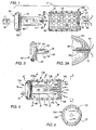
- This invention relates to interbody bone fusion devices, and more particularly to an apparatus and method for the delivery of electrical current to a spinal fusion implant and to interbody fusion material for inducing bone growth and aiding in spinal arthrodesis.
- the spine may be fused along any of its various surfaces or internally within the interspaces of the vertebrae.
- Various interbody fusion devices have been developed to promote interbody fusions of the spine, such as that of Michelson, U.S. Patent No. 5,015,247 issued on May 24, 1991 , Brantigan U.S. Patent No. 4,743,256 issued on May 10, 1988 , and others.
- Such devices have helped to achieve spinal fusion by providing structural support, presenting bone promoting substances to the fusion site, increasing the surface area available to participate in the fusion, and by being both self-stabilizing and stabilizing to a spinal segment.
- the application of electrical current to negatively charge a site in which spinal fusion is desired simulates the bone's own normal repair process and promotes osteogenesis.
- the application of electrical current to negatively charge a site in which osteogenesis is desired creates an electrochemical reaction (4e- + O 2 +2H 2 O) ---> 40H - ) which lowers the oxygen tension (decreasing the O 2 ) to stimulates osteoblastic activity and promotes bone formation.
- the formation of the hydroxyl radical (OH - ) raises the local tissue pH which of itself is favorable to bone production and further promotes increases in the presence of alkaline phosphatase, a very potent stimulant of bone formation in it's own right.
- the application of electrical current to positively charge an area of bone inhibits osteogenesis and thus inhibits bone formation. Therefore, the application of electrical current to deliver positive charge to an area of bone may be used to control the bone fusion process so that it does not occur in undesired areas such as within the spinal canal.
- the bone fusion process is a race against time, for eventually, the body will give up its attempt to complete that process.
- Well-known within the field of surgery is the use of electrical current delivered internally, or applied externally relative to a patient's body to promote bone growth and thus promote the bone healing or fusion process.
- none of the interbody fusion devices of the past incorporate the use of electric current to stimulate bone growth, to increase the rate of osteogenesis and the spinal fusion process.
- the first is the use of an internally implanted electrical pulse generator, with a cathode wire leading from the pulse generator being wrapped about a bone plug harvested from the patient's body which is then inserted into the intervertebral space.
- These devices however have been continually plagued with problems that include breakage of the lead wires from the generator to the fusion site and second surgery to remove the generator implanted in the patient's body at a remote location to the fusion site after the service life of the battery has expired.
- the power supplies to these implantable generators have been ineffective due to their limited service life, which may be shorter than the time needed to attain solid fusion; and problematic due to the potential for tissue damage in the event of a leak.
- the latter concern prompts most physicians to perform a second surgical procedure to explant the generator and internal battery supply. The additional surgery to explant the device increases the risk of infection and danger to the patient, and results in unnecessary additional costs.
- the invention provides a system to promote bone growth between at least two adjacent bone masses in a patient according to claim 1. Further embodiments of the invention are described in the dependent claims.
- the present invention is directed generally to an apparatus and method for the delivery of electrical current to a surgically implanted device in a location in which bone growth is desired. More specifically, the present invention discloses an electrical bone growth promotion (EBGP) spine fusion implant positioned within the intervertebral space between two adjacent vertebrae of the spine to promote and induce bone growth in the spinal fusion process.
- the EBGP implant of the present invention comprises a power supply and related control circuitry for deliverying electrical current directly to the housing of the EBGP implant which is surgically implanted within the intervertebral space between two adjacent vertebrae.
- the housing of the EBGP implant of the present invention is at least in part electrically conductive such that at least a portion thereof serves as an active cathode to deliver negative charge directly to the spinal fusion site and to any bone material contained within the EBGP implant and thus directly to the area in which the promotion of bone growth is most desired.
- the areas of bone growth promotion may be controlled either by conducting only negative charges to the location for bone growth promotion is desired or by conducting negative charges to the area in which bone growth promotion is desired and at the same time conducting positive charges to any area in which bone growth is to be inhibited.
- the housing or a portion thereof services as an active cathode for delivering negative charge or a combination active cathode and active anode for delivering negative charge and for delivering positive charge, respectively to bone mass.
- the EBGP implant of the present invention is not limited in its use with any particular spinal fusion implant.
- Many different embodiments of the EBGP implant of the present invention are possible.
- an implantable power supply and related control circuitry are completely contained within a hollow central chamber of the housing of the EBGP implant such that the EBGP implant is a self-contained unit positioned within the intervertebral space between two adjacent vertebrae of the spine and may deliver electrical charge directly to the fusion site to promote spinal arthrodesis.
- the power supply and control circuitry may be contained in an extending portion of a cap used to close one end of the hollow central chamber of the housing and thus may be inserted into the EBGP implant which itself may in the remainder be filed with bone.
- the EBGP implant of the present invention is a self-contained unit which overcomes the problems described above associated with the prior art devices for delivering electrical current to promote bone fusion.
- the EBGP implant of the present invention conducts electrical current via its housing, or a portion thereof, to an area of bone adjacent to the EBGP implant in which the promotion of bone growth is desired. As no lead wires are present, the problem of breakage of such wires experienced by the devices of the past has been overcome. Further, as the power supply and related control circuitry are fully contained within the EBGP implant of the present invention there is no need to implant a power supply and/or said related control circuitry at a remote location from the EBGP implant.
- the external housing of the EBGP implant, the threaded portion, or any part of the housing of the EBGP implant may be utilized as an active cathode by coupling the cathode lead from the power supply and/or control circuitry contained within the EBGP implant to the housing or a portion thereof.
- the housing may be spinal fusion implant such as that described by Michelson in U.S. Patent No. 5,015,247, issued on May 14, 1991 , and could utilize its continuous external thread much like a wound coil with the threaded portion being separated from one another and from the remainder of the spinal implant by an electrically non-conductive ceramic material, and further that non-conductive material itself may also be osteoinductive.
- the housing of the EBGP implant further includes an opening through which bone growth from one vertebra to a second adjacent vertebra may occur. Coaxial with the opening is a coil that is coupled to the cathode lead of the power supply. The coil acts as an active cathode to deliver a negative charge and promote bone growth through the opening and coil. In a further modification of this variation the cathode continues as a coil about the housing of the EBGP.
- any of a number of already known or conventional surgically implantable power supply units and related control circuitry may be placed within the body of the patient at a location remote to the spine.
- a lead wire couples the power supply and/or control circuitry to the housing of the EBGP implant, such as a spinal fusion implant, situated within the intervertebral space between and in contact with two adjacent vertebrae.
- the EBGP implant which is at least in part not made of bone, and that part also being electrically conductive, is used to conduct electrical current to the interbody spinal fusion mass.
- the entire housing of the EBGP implant is electrically conductive and functions as an active cathode to deliver negative charge to the area of bone adjacent thereto.
- the housing of the EBGP implant may be made of a combination of electrically conductive and non-conductive materials such that a first portion of the housing of the EBGP implant is an active cathode specifically utilized of for the delivery of the negative electrical charge as discussed above for the first variation of the first embodiment and a second portion of the housing is an active anode specifically utilized to deliver positive charge to the area in which bone growth is not desired.
- the area of the anode may be minimized to reduce the area in which borie growth is inhibited or may be larger such that the anode is used to prevent bone formation over a substantial area.
- electrical current may be conducted only to the threads of the housing or to a wire coil insulated from the remainder of the housing. In this manner less current is drained from the power supply without reducing the effectiveness of the electrical charge delivered to the site in which bone fusion is desired since the electrical field created about the coil or threads extends beyond the coil of the threads.
- a spinal fusion implant is preferably implanted surgically within the intervertebral space between two adjacent vertebrae and is wholly or partially ferromagnetic.
- the spinal fusion implant is hermetically sealed in a jacked composed of a non-ferromagnetic, biocompatible material which may or may not be electrically conductive.
- An electromagnetic field is produced by an electromagnetic coil or coils worn external to the patient's body.
- the spinal fusion implant may be inductively coupled to the electromagnetic fields generated and transmitted by the external coils, and thereby generate its own electromagnetic field and accompanying electrical currents. These internal fields and currents are localized within that segment of the spine in which the spinal fusion implant is located and will induce bone growth and promote the spinal fusion process.
- the EBGP implant is wholly or partially powered by electrical currents induced within the EBGP implant by the externally-applied electromagnetic fields.
- any battery source integrated into the EBGP implant may be recharged via such electromagnetic induction to renew the service life of the battery source and thus extend the period of time in which bone growth may be electrically promoted.
- the EBGP implant in this embodiment delivers electrical current and replenishes the power supply when inductively coupled to externally applied electromagnetic fields.
- the power supply is surgically implant within the body of the patient but at a location remote to the spine such as a subcutaneous implantation and is rechargeable in response to the application of external magnetic fields.
- the battery source is charged by an external power source by ferromagnetic induction and continues to deliver charges via that battery source even after the activity of the external coil ceases.
- the electrical bone grown promotion (EBGP) implant of the present invention is shown and is generally referred to by the number 10.
- the EBGP implant 10 comprises a housing 30 as shown in Figure 2 which is implanted in the intervertebral disc space S between adjacent vertebrae V 1 and V 2 in a segment of the spine for achieving arthrodesis.
- housing 30 includes a hollow tubular body that is at least partially cylindrical having side walls 34 and preferably made of an surgically implantable and electrically conductive material such as, but not limited to, titanium.
- the housing 30 has a hollow central chamber 36 that is open at its distal end 38, is closed at its proximal end 40 and has a series of macro-sized opening 42 perforating the side walls 34.
- the macro-sized openings 42 preferably have a diameter in the range of approximately 2.0 mm to approximately 6.0mm to allow for the macro fixation of the adjacent vertebrae V 1 and V 2 .
- bone growth occurs from each of the two adjacent vertebrae V 1 and V 2 through the macro-sized openings 42 to any natural or artificial bone fusion enhancing material that may be contained within the central chamber 36 so as to form a single solid mass.
- the housing 30 has a similar structure and configuration of a spinal implant such as, but not limited to, the spinal fusion implant taught by Michelson in U.S. Patent No. 5,015,247 .
- the housing 30 is preferably, at least in part, electrically conductive and is made of material stronger than bone to provide structural support to the two adjacent vertebrae V 1 and V 2 while awaiting bone ingrowth, becoming firmly and permanently fixed in place once bone growth has occurred.
- the housing 30 may be coated with a bone growth inducing material such as, but not limited to, hydroxyapatite, hydroxyapatite tricalcium phosphate, bone morphogenic protein and the like.
- the housing 30 may also have a surface configuration that enhances bone growth such as, but not limited to surface knurling or roughening.
- the open distal end 38 has internal threads 39 and is closable with a cap 50 having at least a portion thereof that is electrically conductive.
- the cap 50 has a threaded end 52 which is threaded to match the internal threads 39 and secured to internal threads 39 by the use of a driver/wrench W or an equivalent tool.
- a casing 80 for containing electrical components discussed in greater detail below.
- the casing 80 is appropriately sized such that it fits within the central hollow chamber 36 of the housing 30 and occupies the least amount of space possible so as to limit interference with the bone fusion process.
- the cap 50 is threadably coupled to the housing 30, the casing 80 is completely contained within the central hollow chamber 36 such that the EGBP implanted 10 is a self-contained unit.
- the EBGP implant 10 is shown surgically implanted in the disc space S between the two adjacent vertebrae V 1 and V 2 . At least a portion of the housing 30 is embedded into the bone of the adjacent vertebrae V 1 and V 2 . However, it is appreciated that for the purpose of the present invention, the housing 30 need not be embedded into the bone of the vertebrae V 1 and V 2' but need only be placed adjacent to and be in contact with vertebrae V 1 and V 2 in order to enable the EBGP implant 10 to conduct electrical current to the adjacent vertebrae V 1 and V 2 .
- electrical current is a function of the time rate of change of electrical charge and the terms current and charge may be alternatively used depending upon context in describing the EBGP implants of the present invention.
- charge is proportional to the resistance encountered by the current, as bone growth occurs the resistance encountered by the current delivered to the bone mass will be increased, such that the charge will decrease. Also as the power supply depletes, the amount of current delivered over time will also decrease.
- the hollow central chamber 36 can be filled with and may hold any natural or artificial osteoconductive, osteoinductive, osteogenic, or other fusion enhancing material.
- bone material B harvested from the patent may be loaded into the central hollow chamber 36 as well as packed around the exterior of the housing 30, but within the intervertebral disc space S. wherein it is utilized in the spinal fusion process.
- An obdurator or similar instrument may be used to create a space in the bone material B for receiving an object therein such as the casing 80.
- the housing 30 may be filled with bone material B and then closed with the cap 50 to hold the bone material B within the hollow chamber 36 during surgical implantation.
- the casing 80 itself, or a portion thereof, is made of an electrically conductive and surgically implantable material such as, but not limited to, titanium such that electrical current applied to the casing 80 may be transferred from the casing 80 to the bone material B that is contained within the hollow central chamber 36.
- the casing 80 may be removably attached to the cap 50 or may be permanently affixed. In the preferred embodiment, the casing 80 is electrically coupled to the cap 50. However, it is appreciated that the casing 80 may be electrically insulated from the cap 50 if it is not desired to conduct as electrical current to the cap 50 having a different polarity from the remainder of the casing 80.
- the electrical components comprising a power supply 60, control circuitry 70, a cathode lead 72, and an anode lead 74. Both the power supply 60 and the control circuitry 70 are fully implantable and hermetically sealed.
- the cathode lead 72 is electrically coupled to the cap 50 either directly or via the casing 80, such that when the cap 50 is threaded to the housing 30, negative electrical charge is transferred to the housing 30 such that the housing 30 itself becomes an active cathode.
- the power supply 60 is electrically coupled to the housing 30 and is located at the site in which spinal fusion is desired.
- the EBGP implant 10 is a self-contained unit, thereby eliminating the need to implant the power supply 60 and related control circuitry 70 at a remote location within the patient's body, as is the case with fusion stimulators of the prior art.
- the control circuitry 70 preferably includes well known means for the delivery of a constant current source, providing a single, preset current in the rang of .01 to 20 uA. Thus, neither attachment of multiple cathodes or variation in cathodic area will alter the current density delivered to the bone fusion mass. It is appreciated that the control circuitry 70 may also include a wave form generator, a voltage generator or a clock means for delivering intermittent pulses of current with out departing from the scope of the present invention. Alternatively, the control circuitry 70 may comprise means for providing various patterns of direct current alternating current, pulsatile current, sinusoidal current, or electrical noise generated by current rather than constant, direct current in order to promote bone growth.
- the electrical components may also comprise any of the well-known devices currently available to electrically stimulate spinal fusion, such as but not limited to the stimulator available from EBI Medical Systems, Parsippany, NJ., and may also be any of the devices suitable for delivering electric current and suitable for implantation well-known by those skilled in the art.
- the control circuitry 70 is powered by the fully implantable, hermetically sealed power supply 60 which may be any of the well-known power supplies known in the art and currently commercially available and used to electrically promote spinal fusion such as, but not limited to, the power supply EBI Medical Systems Parsippany, NJ.
- the power supply 60 also may contain circuitry for generating electrical charge in response to externally applied electromagnetic fields.
- the power supply 60' may include battery recharge circuitry responsive to externally applied electromagnetic fields for recharging the battery.
- the overall size of the power supply 60' may be substantially reduced with a corresponding reduction in the size of the casing 80'. In this manner, any interference with the bone fusion process by the casing 80' is further reduced.
- the longevity of the power supply 60' may be substantially increased as the power supply 60' may be recharged to extend its life beyond that of a conventional non-rechargable battery having a fixed service life.
- the electric promotion of osteogenesis may be extended beyond the service life of conventional prior art devices with their non-rechargable batteries.
- the rechargeable power supply 60' may be reduced in size as the service life may be extended indefinitely, compactness of power supply such that bone growth promoting bone material is not displaced which is essential for fusion.
- cap 50' which may be secured to the housing 30 by a spring fastening means 52' which engages the interior surface of the housing 30 once the spring fastening means 52' is inserted in the central hollow chamber 36.
- the time required to load bone material B within the central hollow chamber 36 and the time to assemble the cap 50' to the housing 30 is significantly reduced.
- the end of the casing 80 includes an insulated screw 90 made of a non-conductive material.
- the screw 90 has a threaded portion 92 which threadably attaches to the casing 80, and has an electrically conductive core 94 passing through the longitudinal axis of the screw 90.
- the electrically conductive core 94 terminates at one end into an electrically conductive head portion 96 and is at its other end electrically coupled to the anode lead 74. In this manner, the head portion 96 becomes the active anode for delivering positive electrical charge to an area of bone.
- the head portion 96 preferably has the smallest possible size to limit the area of contact to bone exposed to positive charge to limit bone area of contract to bone exposed to positive charge to limit bone resorption and is positioned at a location where the presence of positive charge will least interfere with the fusion process.
- the head portion 96 is located at the tip of the end of the casing 80 such that when the cap 50 is attached to the housing 30, the head portion 96, and thus the active anode, is at a located which least interferes with the electrical promotion of the bone material B contained with the central chamber 36 and has substantially no contact with the adjacent vertebrae V 1 and V 2 to which fusion is desired.
- An exampled of the electrical current present in the EBGP implant 10 is illustrated the electrical field arrows in Figure 2.
- the promotion of bone growth may be controlled by the application of negative electrical current only to the location in which bone growth is desired. For example, if bone growth promotion is desired at a particular location, negative current may be transferred to the housing 30 or a portion thereof which is adjacent to and in contact with a desired site in order to accelerate the fusion process. In areas where bone growth is not desired, such as near the canal of the spine for example, positive current may be transferred to the desired site.
- an insulated screw 20 having a conductive inner core 22 is threaded through an opening 24 in the proximal end 40.
- the insulated screw 20 has a recess 26 for receiving and coupling to the head portion 96. In this manner, positive charge is conducted by the conductive inner core 22 to a point external to the housing 30.
- the EBGP implant 110 comprises a housing 130 similar to the housing 30 described above, except that it has a proximal end 140 that is at least in part insulated from the remainder of the housing 130.
- the housing 130 has macro-sized openings 142 to permit bone grown therethrough.
- Anode lead 174 from the power supply 100 and/or control circuitry 170 may be electrically coupled to the proximal end 140 of the housing 130 so that the proximal end 140 may be positively charged.
- the proximal end 140 has a screw 120 having a conductive screw head 121, a conductive inner core 122, and an insulated stem portion 123 having a recess 126 for coupling to the head portion 196 (the active anode.)
- the inner core 122 conducts positive charge from the head portion 196 to the conductive screw head 121.
- the screw head 121 is insulated from the housing 130 by an insulated ring 125 made of a non-electrically conductive material so that the screw head 121 can conduct positive charge to a point external to the housing 130 so that at least a portion of the proximal end 140 of the housing 130 becomes positively charged as illustrated by the electrical field arrows in Figure 4.
- the area of positive charge may be varied in size by varying the area of the screw head 121, and thus the area of potential promotion of bone resorption is also variable. As shown in Figure 4, the area of screw head 121 has been deliberately increased to inhibit bone formation in an area adjacent to the screw head 121.
- the configuration of electrical charges shown in the EBGP implant 110 would be utilized when the housing 130 is installed from the posterior aspect of the spine toward the anterior aspect of the spine since the proximal end 140 of the EBGP implant 110 would be proximate to the spinal canal once implanted in the disc space S between two adjacent vertebrae V 1 and V 2 .
- By conducting positive charges to the proximal end 140 osteogenesis in the spinal canal which could compress the neutral structures is inhibited.
- the positively charged screw 120 would have a screw head 121 proportionally much smaller in size to limit the area of positive electrical charge.
- the cathode lead 172 from the power supply 100 and/or control circuitry 170 is coupled to the casing 180 and negative charges are conducted to the housing 130 by the contact of the casing 180 and cap 150 with the housing 130 such that the housing 130 itself becomes an active cathode.
- the delivering of positive charges and the negative charges may be reversed simply by interchanging the anode lead 174 and the cathode lead 172 coupling points to the housing 130, cap 150, distal end 140, or screw 120. In this way, negative charge may be applied and directed only to the particular areas in which bone growth is desired depending on the type of surgery, bone growth, and fusion desired.
- the distal end 138 of the housing 130 would be proximate to the spinal canal.
- the distal end 138 of the housing 130 or a portion thereof, which when implanted is adjacent to and in contact with the bone near the housing 130 may be insulated from the remainder of the housing 130.
- the distal end 138 may be positively charged by being connected to the anode lead 174 of the generator 170 so that the proximal end 138 itself serves as an active anode. This can be accomplished by having an insulated screw 156 having an electrically conductive core 158.
- the electrically conductive core 158 becomes the active anode and delivers positive electrical charge to the adjacent bone area.
- bone area adjacent to and in contact with the distal end 138 would be exposed only to positive charge and not to bone growth promoting negative charge.
- the diameter of the electrically conductive core 158 may extend from the insulated screw 156 and may be decreased in size to limit the bone area being exposed to positive electrical charge.
- the application of different polarity charges to different areas of the housing 130 may also be accomplished by having the threads 152 of a cap 150 coated with a nonconductive material such as, but not limited to, a ceramic material in order to insulate the cap 150 from the remainder of the housing 130 such that the cap 150 becomes the active anode when connected to the anode lead 174 and is positively charged.
- a nonconductive material such as, but not limited to, a ceramic material
- This will prevent electrical promotion of bone growth in the vicinity of the cap 150 which is adjacent to the spinal canal and in contact with the bone near the spinal canal when implanted.
- other means of insulating the distal end 138 well-known by those skilled in the art, may be employed so that the distal end 138 has a different charge than the remainder of the housing 130 or has no charge at all.
- the EBGP implant 210 comprises a housing 230 similar to the housing 30 described above.
- the exterior of the housing 230 has external threads 200 which are formed on the outer circumference of the housing 230 preferably in a helix.
- the threads 200 of the housing 230 are electrically conductive and have a non-conductive insulating material 202 separating the threads 200.
- the insulating material 202 may be ceramic or polyethylene or any other biocompatible material that has electrical insulating properties.
- the housing 230 may be completely or partially hollow and threads 200 service as the active cathode to conduct negative charge to the bone area in which the housing 230 is implanted and any material that may be within the housing 230.
- the insulating material 202 is interposed between the threads 200 themselves and between the housing 230 itself, the threads 200 are isolated from the remainder of the housing 230 and essentially act as a coil that surrounds to exterior of the housing 230.
- the threads 200 are electrically connected to the cathode lead 74 (See Figure 1) of the control circuitry 70 described above and thus the threads 200 function as a cathode to deliver negative charge from the EBGP implant 210 to the vertebra V adjacent to the housing 230 and material contained within the housing 230 if any.
- the advantage of this arrangement is that only the coil threads 200 are charged rather than the external housing 230 and since the beneficial electrical effect to some instance from each of the threads 200, the threads 200 are an effective cathode lead with less current drain than would be required to charge the external housing 230.
- the threads 200 it is possible to configure the threads 200 such that at least a portion thereof passes through the insulating material 202 and communicates with the central chamber 236 so as to also conduct electric charge to any material contained within the housing 230 as illustrated by the electrical field arrows.
- This design requires that either the inward or outward portions of the threads 200 not be continuous such that the integrity of the housing 230 is not substantially reduced.
- the housing 230 has macro-size openings 242 to permit bone-growth therethrough.
- the EBGP implant 310 comprises a housing 330 similar to the housing 30 described above, having threads 300 and a wire 350 placed between the threads 300.
- the wire 350 is supported by a non conductive insulating material 350 that is placed between the threads 300 of the housing 330.
- the insulating material 360 has a groove 362 for receiving and holding the wire 350.
- the wire 350 is electrically coupled to a cathode lead such as the cathode lead 72 of the generator 70 (shown in Figure 1) and is negatively charged such that wire 350 conducts bone growth promoting negative charge to the bone area of the adjacent vertebrae V 1 and V 2 adjacent to the coiled wire 350 and through the openings 342 to the fusion mass within the housing 330.
- the insulating material 360 prevents the body of the housing 330 from becoming electrically charged and prevents electrical conduction between wire 350 and threads 300 and housing 230 and any short circuiting of the coiled wire 350. In this manner, the area of the EBGP implant 310 which is electively charged is limited to the coiled wire 350 to significantly reduce the total area which is electrically charged.
- the coiled wire 350 essentially extends approximately the entire longitudinal length of the EBGP 310, it is possible to deliver electrical charge to the entire area of bone adjacent to the EBGP 310 to stimulate bone growth without any diminished effect.
- the EBGP implant 310 is energy efficient since the amount of electrical current required to power the EBGP implant 310 is substantially less than that required for an implant where the entire implant housing is charged.
- the EBGP implant 410 comprises a housing 430 similar to the housing 30 and having an opening 420 having an axis that is perpendicular to the longitudinal axis L of the housing 430.
- the opening 420 passes through the housing 430 and communicates with the central chamber 436 of the housing 430 and is surrounded by four structural support members 421, 422, 423 and 424.
- the opening 420 is covered by a lattice 415 at both ends.
- the lattice 415 has openings 416 sufficiently sized to permit bone growth therethrough yet remains capable of retaining any natural or artificial bone growth material that may be contained within the hollow central chamber 436.
- FIG. 15 an enlarged perspective view of structural support member 421 is shown.
- the structural support member 421 made of an electrically non-conductive material, has an upper arm 440 and a lower arm 442 that are placed in the hollow central chamber 436 and are secured to the spinal implant 430; a central portion 443 having a curved outer edge 444; and a grooved inner edge 446.
- the inner edge 446 of the structural support member 421 has a plurality of grooves 448 for receiving and holding a wire 425 capable of conducting electrical current.
- the plurality of grooves 448 are offset from each other and follow the curvature of the outer edge 444 of the structural support member 421.
- the four structural support members 421-424 are arranged around the outer perimeter of the opening 420 such that they are equidistant from one another.
- the wire 425 is placed within the grooves 448 and coiled about the four structural support members 421-424 to form a wire coil 426 around the perimeter of the opening 420 substantially along the entire vertical length of the opening 420 that is coaxial with the opening 420.
- the wire coil 426 is electrically coupled to a cathode lead 472 and delivers and delivers a negative charge to the area surrounding within the torroid opening 420 such that bone growth is promoted and stimulated by the presence of negative charge along the inner and outer walls of the torroid shaped wire coil 426.
- the opening 420 is filled with bone or bone promotion substances and the electrical promotion of bone growth causes bone of the adjacent vertebrae V 1 and V 2 to grow into and through the vertical openings 420 into that bone or bone promoting substances from one vertebrae V 1 to the other vertebrae V 2 .
- control circuitry 470 and the power supply 460 are contained within the central chamber 436 of the housing 430 such that the EBGP implant 410 is a self-contained unit.
- the wire coil 426 is coupled directly to a cathode lead 472 such that the wire coil 426 becomes negatively charged.
- control circuitry 470 and power supply 460 may be implanted in an area of the patient's body remote from the EBGP implant 410.
- the cathode lead 472 may be coupled directly to the wire coil 426 via lead wire 462 or may be coupled to the body of the housing 430 which is electrically conductive, and the wire coil 426 may also be electrically coupled to the housing 430 so that the housing 430 becomes electrically charged.
- the wire coil 426 be connected to either a wire coil such as described above in reference to Figures 9 and 10 or threads 200 as described above in reference to Figures 7, 8A and 8B. In this manner, efficient use of the power supply 460 is made as the drain is reduced without diminishing the effectiveness of the electrical promotion of bone growth as discussed above.
- the EBGP implant 510 comprises a housing 530 having a non-electrically conductive cap 550 threaded to its distal end 538, and a remotely implanted power supply 560 and control circuitry 570 connected to the housing 530.
- the housing 530 itself is negatively charged when coupled to the cathode lead 572 and the cap 550 has no electrical charge.
- the power supply 560 is electrically connected to the housing 530 by the cathode 572 which terminates at a connector 590 which is attached by a screw 592 to the housing 530.
- a remotely implanted power supply and/or related control circuitry may be used to deliver electric current to any of the embodiments described above that are self-contained units having an internal power supply and generator, without departing from the scope of the present invention.
- the EBGP implant 610 comprises an electromagnetic field transmitter 600 that is worn external to the patient's body.
- the transmitter 600 has two portions 602 and 604 which are secured to the patient's body by a band 610 or any other suitable means, such that each portion 602, 604 is place on opposite sides of the body at the exterior of the patient's body.
- Implanted between two adjacent vertebrae V 1 and V 2 of the patient is a housing 630 similar to the housing 30 described above.
- the housing 630 is at least in part ferromagnetic and thereby capable of being inductively coupled to the electromagnetic fields transmitted by the transmitter 600.
- the EBGP implant 610 thereby may be inductively coupled to transmitter 600 and this manner electromagnetic fields and resultant induced electrical currents in EBGP implant 610 may be concentrated and directed to a location in which bone growth is desired without the need for surgically implanting and a power supply and/or control circuitry within the housing 630 or within the body of the patient.
- the non-ferromagnetic portion of the housing 630 also may be electrically conducive, which would make the housing 630 capable of being inductively coupled to the electromagnetic fields transmitted by the transmitter 600 as well as a conductor of electrical currents induced by said externally applied electromagnetic fields.
- the power supply 660 may be recharged with the application of external electromagnetic fields via the transmitter 600.
- the power supply 660 could be much smaller in size as the power supply 660 may be repeatedly recharged.
- both the housing 630 and the power supply 660 may be inductively coupled to the transmitter 600, such that the housing 630 delivers electrical current to the adjacent bone mass and the power supply 660 is being recharged.
- the replenished power supply 660 continues to deliver electrical current to the housing 630.
- the period of time in which a patent must wear the transmitter is substantially reduced to the period of time required to replenish the power supply 660, while maintaining a continuous delivery of electrical current to the housing 630.
- a rechargeable power supply 660 may be implanted remote to the spine, preferably subcutaneously, such that the power supply 660 is easily rechargable via electromagnetic induction.
- the inductive coupling of a subcutaneous power supply 660 with the electromagnetic transmitter 600 overcomes the problems of infection associated with any direct coupling of a power supply to a power source. Further subcutaneous implantation of the power supply 660 also facilitates explantation of the power supply 660 and further reduced the risk of infection to the patent. In contrast to implantations in other areas of the body.
- the housing 730 has a substantially rectangular hollow configuration and has a tapered distal end 738.
- the housing 730 has an upper surface 750 and a parallel lower surface 752 and two side walls 754 and 756.
- the housing 730 has a series of small openings 760 through the upper and lower surface 750 and 752 and through the side walls 754 and 756 for permitting bone growth there through.
- Contained within the spinal implant 730 are the power supply 760 and the control circuitry 770 so that the spinal implant 730 is a self-contained unit.
- the power supply 760 and/or control circuitry 770 are electrically coupled to the hosing 730 by a cathode lead 762 and an anode lead 764.
- the anode lead 764 is coupled to an insulating screw 756 having an electrically conductive core 758.
- the insulating screw 756 is threaded into the EBGP implant 710 and insulates the anode lead 764 from the rest of the EBGP implant 710.
- the EBGP implant 810 is much like the seventh alternative embodiment except that the housing 830 has a hollow rectangular configuration with raised engagement teeth 880 for engaging the bone of adjacent vertebra V and has a wire 850 similar to wire 350 described above, coiled about the housing 830.
- the wire 850 is insulated from the housing 830 by an insulating material 860 having a groove 862 for receiving the wire 850.
- the insulating material is identical to insulating material 360 discussed above.
- the EBGP implant 810 is also a self-contained unit as the power supply 860 and/or the control circuitry 870 are contained within the hollow chamber of the spinal implant 830 and are electrically coupled to the wire 850.
- the EBGP implant of the present invention is not limited to use in the spinal fusion process but is also applicable to promoting almost any fusion of a large joint and for promoting healing of a fracture any of the major bones of the body.
- the apparatus and method of the present invention may be incorporated into various total knee arthroplasty and total hip arthroplasty.
- Such implants may embody the above-described teachings without departing from the scope of the present invention.
- Such implants may be wholly or partially electrically conductive having a permanent or rechargeable power supply and related control circuitry located within the implant itself such that the implant is a self-contained unit.
- a renewable power source is of great advantage with such implants in that the bone fusion process, or the healing of the larger bones such as the femur or hip, for example, may require a longer period of time for bone healing fusion than the service life of the implantable permanent power supplies that are presently utilised.
- the recharging of the power source through external charging can extend the delivery of electrical current to the site in which induction of osteogenesis is desired for a substantially greater period of time.
- implants may also comprise externally applied electromagnetic coils to generate an electromagnetic field that may be inductively coupled to the implant which in turn delivers electrical changes to the areas of bone adjacent to the implant as described in greater detail above and recharge the power supply by electromagnetic induction from an externally applied electrical field. All of such implants have the added advantage in that once implanted they become permanently entombed within the bone fusion mass after completion of the fusion process and need not be surgically removed.
- an electrical bone growth promotion implant for placement between selected adjacent bone masses and for promoting bone growth and bone fusion
- the implant according to the first aspect preferably includes control means for controlling delivery of said electrical charge.
- the control means preferably includes a wave form generator.
- the control means preferably includes a voltage generator.
- the control means includes a clock means for delivering intermittent pulses of current.
- the control means includes means for providing alternative current.
- the control means preferably includes means for providing direct current.
- the control means includes means for providing a sinusoidal current.
- the control means includes means for generating electrical noise.
- the power means preferably comprises means for being inductively coupled to an electromagnetic field generating means positioned external to the patient's body.
- the housing means preferably has a substantially hollow central chamber, said hollow chamber having at least one access opening.
- the power supply preferably is completely contained in said hollow chamber.
- the implant preferably includes control means for controlling delivery of said electrical charge, wherein the control means being completely contained within said hollow chamber.
- the implant preferably includes a cap for closing said access opening of the central hollow chamber.
- the control means is preferably attached to said cap.
- the power means is preferably attached to said cap.
- the power means preferably delivers negative electrical charge to said first portion of said housing means.
- the power means preferably delivers positive electrical charge to a second portion of the implant.
- the power means preferably comprises a surgically implantable battery.
- the battery is preferably rechargeable.
- said housing means preferably comprises an external coil, said coil being electrically conductive and being electrically insulated from said housing by a non-conductive material.
- said external coil preferably comprises a plurality of external threads on the exterior of said implant.
- Said plurality of external threads preferably is coupled to said power means.
- Said housing means preferably includes a hollow central chamber, said plurality of external threads having means for contacting electrical current to said hollow central chamber.
- said housing means preferably has a longitudinal access and an opening perpendicular to said longitudinal axis, said opening passing completely through said housing means, a conductive coil means coaxial with said opening, support means for supporting said coil, said support means being electrically non-conductive, said coil being coupled to said power means and delivering electrical current to said opening to promote bone growth through said opening.
- the housing means preferably comprises a hollow central chamber in communication with said openings and said coil.
- Said power means preferably is completely contained within said hollow chamber.
- the implant preferably further includes a control means for operating said generating means, said control means being completely contained within said hollow chamber.
- an implant for delivering electric current for promoting bone growth and bone fusion comprising housing means having a first portion being electrically conductive, receiving means for receiving electromagnetic energy, said receiving means being electrically coupled to said housing, and generating means for generating electromagnetic energy from a point external to a patient's body, said generating means being inductively coupled to said receiving means.
- the implant according to the second aspect preferably includes means for delivering a charge of predetermined polarity to an area of bone adjacent to said implant.
- the implant preferably further includes means for storing electrical current generating by said generating means.
- a method for promoting bone growth and bone fusion within an implant surgically implanted into the bone to be fused comprising the steps of providing negative charge to at least said first portion of said implant to promote bone growth in the area of bone adjacent to said first portion.
- the method preferably includes the step of providing positive charge to a second portion of said implant to inhibit bone growth in an area of bone adjacent to said second portion.
- a self contained implantable medical device for placement contiguous to selected bone masses for promoting growth of such bone masses, the medical device including a source of electrical charge, and means for delivering charge from the charge source to the selected bone masses.
- the selecting means preferably includes means to deliver negative charge to a first location of bone mass and positive charge to a second location of bone mass.
- a self contained implantable medical device for placement between selected adjacent bone masses for promoting interbody arthrodesis, comprising housing means for placement between and in contact with adjacent bone masses, the housing means having a first portion being electrically conductive, charge means contained within the housing means for providing electrical charge at a predetermined polarity, and means interposed between the charge means and said first portion for transferring charge from the charge means to the first portion to thereby promote inter-body arthrodesis.
- the housing means preferably comprises a cylinder having substantially hollow central member, the cylinder having at least one access opening for receiving the charge means.
- the cylinder preferably includes a plurality of annularly disposed perforations.
Abstract
an implant (30) having opposed first and second portions for placement between and in contact with the adjacent bone masses, each of said first and second portions have at least one opening (42) adapted to permit bone growth from adjacent bone mass to adjacent bone mass though said implant; and
a power supply (60) for energizing said implant to promote bone growth, said power supply being adapted to energize said implant from a point external to a patient's body.
Description
- This application is a continuation in part of application serial No.
08/052,211 filed on April 22, 1993 no. 07/546,849 filed on July 2, 1990 No. 07/212,480, filed on June 28, 1988 - This application is also a continuation in part of application serial
No. 07/968,240 filed on October 29, 1992 no. 07/698,674 filed on May 10, 1991 no. 07/205,935 filed on June 13, 1988 U.S. Patent No. 5,015,247 on May 14, 1991 . - This invention relates to interbody bone fusion devices, and more particularly to an apparatus and method for the delivery of electrical current to a spinal fusion implant and to interbody fusion material for inducing bone growth and aiding in spinal arthrodesis.
- The spine may be fused along any of its various surfaces or internally within the interspaces of the vertebrae. Various interbody fusion devices have been developed to promote interbody fusions of the spine, such as that of
Michelson, U.S. Patent No. 5,015,247 issued on May 24, 1991 ,Brantigan U.S. Patent No. 4,743,256 issued on May 10, 1988 , and others. Such devices have helped to achieve spinal fusion by providing structural support, presenting bone promoting substances to the fusion site, increasing the surface area available to participate in the fusion, and by being both self-stabilizing and stabilizing to a spinal segment. - During normal bone repair, the area around the fracture of the bone exhibits negative charge. The application of electrical current to negatively charge a site in which spinal fusion is desired simulates the bone's own normal repair process and promotes osteogenesis. The application of electrical current to negatively charge a site in which osteogenesis is desired, creates an electrochemical reaction (4e- + O2 +2H2O) ---> 40H-) which lowers the oxygen tension (decreasing the O2) to stimulates osteoblastic activity and promotes bone formation. Further, the formation of the hydroxyl radical (OH-) raises the local tissue pH which of itself is favorable to bone production and further promotes increases in the presence of alkaline phosphatase, a very potent stimulant of bone formation in it's own right. Still further, there appears to be a direct effect of electrical current to present a negative charge at the cellular level so as to upset the resting electrical potential of the cell membrane with a resultant electrical perturbation within the cell, the net effect of which is promotional to the cellular activity of bone formation. Finally, the electromagnetic field generated by the passage of electrical current appears to be independent of that current (on the basis of magnetism alone) to be promotional of bone growth, though the mechanism remains unknown.
- Conversely, the application of electrical current to positively charge an area of bone inhibits osteogenesis and thus inhibits bone formation. Therefore, the application of electrical current to deliver positive charge to an area of bone may be used to control the bone fusion process so that it does not occur in undesired areas such as within the spinal canal.
- The bone fusion process is a race against time, for eventually, the body will give up its attempt to complete that process. Well-known within the field of surgery is the use of electrical current delivered internally, or applied externally relative to a patient's body to promote bone growth and thus promote the bone healing or fusion process. However, in regard to the spine, none of the interbody fusion devices of the past incorporate the use of electric current to stimulate bone growth, to increase the rate of osteogenesis and the spinal fusion process.
- To date the use of electric current to promote bone growth in the spinal fusion process has taken two forms. The first is the use of an internally implanted electrical pulse generator, with a cathode wire leading from the pulse generator being wrapped about a bone plug harvested from the patient's body which is then inserted into the intervertebral space. These devices however have been continually plagued with problems that include breakage of the lead wires from the generator to the fusion site and second surgery to remove the generator implanted in the patient's body at a remote location to the fusion site after the service life of the battery has expired. The power supplies to these implantable generators have been ineffective due to their limited service life, which may be shorter than the time needed to attain solid fusion; and problematic due to the potential for tissue damage in the event of a leak. The latter concern prompts most physicians to perform a second surgical procedure to explant the generator and internal battery supply. The additional surgery to explant the device increases the risk of infection and danger to the patient, and results in unnecessary additional costs.
- The second form in which electric current has been used in the past to stimulate spinal fusion required the wearing, external to the body of the patient, of an electromagnetic coil or coils. Unfortunately, neither of these methods when utilized in conjunction with the known methods of interbody arthrodesis has proven fully effective.
- Therefore, a need exists for the means and method of improving upon and/or perfecting the conjoined use of an improved interbody fusion device other than bone alone, and the promotion of bone growth with electrical current.
- The invention provides a system to promote bone growth between at least two adjacent bone masses in a patient according to
claim 1. Further embodiments of the invention are described in the dependent claims. - The present invention is directed generally to an apparatus and method for the delivery of electrical current to a surgically implanted device in a location in which bone growth is desired. More specifically, the present invention discloses an electrical bone growth promotion (EBGP) spine fusion implant positioned within the intervertebral space between two adjacent vertebrae of the spine to promote and induce bone growth in the spinal fusion process. The EBGP implant of the present invention comprises a power supply and related control circuitry for deliverying electrical current directly to the housing of the EBGP implant which is surgically implanted within the intervertebral space between two adjacent vertebrae. The housing of the EBGP implant of the present invention is at least in part electrically conductive such that at least a portion thereof serves as an active cathode to deliver negative charge directly to the spinal fusion site and to any bone material contained within the EBGP implant and thus directly to the area in which the promotion of bone growth is most desired. As positive charges do not promote bone growth, but actually induce resorption of bone, the areas of bone growth promotion may be controlled either by conducting only negative charges to the location for bone growth promotion is desired or by conducting negative charges to the area in which bone growth promotion is desired and at the same time conducting positive charges to any area in which bone growth is to be inhibited. Thus, the housing or a portion thereof, services as an active cathode for delivering negative charge or a combination active cathode and active anode for delivering negative charge and for delivering positive charge, respectively to bone mass.
- As an electrical bone growth promotion apparatus, the EBGP implant of the present invention is not limited in its use with any particular spinal fusion implant. Many different embodiments of the EBGP implant of the present invention are possible. For example, in a first embodiment of the EBGP implant, an implantable power supply and related control circuitry are completely contained within a hollow central chamber of the housing of the EBGP implant such that the EBGP implant is a self-contained unit positioned within the intervertebral space between two adjacent vertebrae of the spine and may deliver electrical charge directly to the fusion site to promote spinal arthrodesis. The power supply and control circuitry may be contained in an extending portion of a cap used to close one end of the hollow central chamber of the housing and thus may be inserted into the EBGP implant which itself may in the remainder be filed with bone.
- The EBGP implant of the present invention is a self-contained unit which overcomes the problems described above associated with the prior art devices for delivering electrical current to promote bone fusion. The EBGP implant of the present invention conducts electrical current via its housing, or a portion thereof, to an area of bone adjacent to the EBGP implant in which the promotion of bone growth is desired. As no lead wires are present, the problem of breakage of such wires experienced by the devices of the past has been overcome. Further, as the power supply and related control circuitry are fully contained within the EBGP implant of the present invention there is no need to implant a power supply and/or said related control circuitry at a remote location from the EBGP implant. Further still, as the power supply and related control circuitry become entombed in the bone mass upon completion of the bone fusion process, no additional surgery is required to explant the power supply and/or control circuitry as was the case with the prior art. Thus, as no explanation is required, the possibility of infection to the patient and other risks inherent to all surgical procedures are eliminated, while also substantially reducing the costs of utilizing electric current to promote bone growth in the bone fusion process.
- In a first variation of the first embodiment, the external housing of the EBGP implant, the threaded portion, or any part of the housing of the EBGP implant, may be utilized as an active cathode by coupling the cathode lead from the power supply and/or control circuitry contained within the EBGP implant to the housing or a portion thereof. For example, the housing may be spinal fusion implant such as that described by
Michelson in U.S. Patent No. 5,015,247, issued on May 14, 1991 , and could utilize its continuous external thread much like a wound coil with the threaded portion being separated from one another and from the remainder of the spinal implant by an electrically non-conductive ceramic material, and further that non-conductive material itself may also be osteoinductive. - In a second variation of the first embodiment, the housing of the EBGP implant further includes an opening through which bone growth from one vertebra to a second adjacent vertebra may occur. Coaxial with the opening is a coil that is coupled to the cathode lead of the power supply. The coil acts as an active cathode to deliver a negative charge and promote bone growth through the opening and coil. In a further modification of this variation the cathode continues as a coil about the housing of the EBGP.
- In second embodiment of the EBGP implant of the present invention, any of a number of already known or conventional surgically implantable power supply units and related control circuitry may be placed within the body of the patient at a location remote to the spine. A lead wire couples the power supply and/or control circuitry to the housing of the EBGP implant, such as a spinal fusion implant, situated within the intervertebral space between and in contact with two adjacent vertebrae. The EBGP implant which is at least in part not made of bone, and that part also being electrically conductive, is used to conduct electrical current to the interbody spinal fusion mass. In one variation of the second embodiment, the entire housing of the EBGP implant is electrically conductive and functions as an active cathode to deliver negative charge to the area of bone adjacent thereto. In a second variation of the second embodiment, the housing of the EBGP implant may be made of a combination of electrically conductive and non-conductive materials such that a first portion of the housing of the EBGP implant is an active cathode specifically utilized of for the delivery of the negative electrical charge as discussed above for the first variation of the first embodiment and a second portion of the housing is an active anode specifically utilized to deliver positive charge to the area in which bone growth is not desired. The area of the anode may be minimized to reduce the area in which borie growth is inhibited or may be larger such that the anode is used to prevent bone formation over a substantial area.
- In order to make efficient use of the power supply, rather than conducting electrical current to the entire housing of the EBGP implant of the present invention which would require a large power supply, electrical current may be conducted only to the threads of the housing or to a wire coil insulated from the remainder of the housing. In this manner less current is drained from the power supply without reducing the effectiveness of the electrical charge delivered to the site in which bone fusion is desired since the electrical field created about the coil or threads extends beyond the coil of the threads.
- In a third embodiment of the EBGP implant of the present invention, a spinal fusion implant is preferably implanted surgically within the intervertebral space between two adjacent vertebrae and is wholly or partially ferromagnetic. The spinal fusion implant is hermetically sealed in a jacked composed of a non-ferromagnetic, biocompatible material which may or may not be electrically conductive. An electromagnetic field is produced by an electromagnetic coil or coils worn external to the patient's body. The spinal fusion implant may be inductively coupled to the electromagnetic fields generated and transmitted by the external coils, and thereby generate its own electromagnetic field and accompanying electrical currents. These internal fields and currents are localized within that segment of the spine in which the spinal fusion implant is located and will induce bone growth and promote the spinal fusion process.
- In a first variation of the third embodiment, the EBGP implant is wholly or partially powered by electrical currents induced within the EBGP implant by the externally-applied electromagnetic fields. Likewise, any battery source integrated into the EBGP implant may be recharged via such electromagnetic induction to renew the service life of the battery source and thus extend the period of time in which bone growth may be electrically promoted. The EBGP implant in this embodiment delivers electrical current and replenishes the power supply when inductively coupled to externally applied electromagnetic fields.
- In another embodiment of the EBGP implant of the present invention, the power supply is surgically implant within the body of the patient but at a location remote to the spine such as a subcutaneous implantation and is rechargeable in response to the application of external magnetic fields.
- In still another embodiment of the EBGP implant of the present invention, the battery source is charged by an external power source by ferromagnetic induction and continues to deliver charges via that battery source even after the activity of the external coil ceases.
- It is an object of the present invention to provide an electrical bone growth promotion implant in which a power supply, related control circuitry, and delivery system are entirely self-contained within a spinal fusion implant, thus eliminating the need to violate other body tissues to situate the implant, thereby limiting the extent of surgery, the time for surgery, the blood loss, and the risk of infection;
- It is another object of the present invention to provide an electrical bone growth promotion implant for delivering electrical current to promote bone growth in a biomechanically and biophysiologically optimal place so as to induce spinal fusion within the compressive weight bearing axis of the spine;
- It is yet another object of the present invention to provide an electrical bone growth promotion implant that eliminates the need for lead wires, the breakage of which has historically been a major source of failure in regard to the use of electrostimulators in general;
- It is a further object of the present invention to provide an electrical bone growth promotion implant in which with successful arthrodesis, the encapsulated power supply and/or related control circuitry becomes permanently entombed in the bone fusion mass thus eliminating the need to perform a second surgical procedure for its removal;
- It is still a further object of the present invention to provide an electrical bone growth promotion implant in which as active cathode is fully contained within the bone fusion mass;
- It is another object of the present invention to provide an electrical bone growth promotion implant in which the power supply and/or related control circuitry combined is an internal extension of either a spinal fusion implant itself or of an insertable cap of the spinal fusion implant;
- It is a further object of the present invention to provide an electrical bone growth promotion implant which will receive externally applied electromagnetic fields and thereby generate electromagnetic fields and electric currents affecting the bone within and adjacent to the space between two adjacent vertebrae; and
- It is yet a further object of the present invention to provide an electrical bone growth promotion implant in which the power source for delivering electric current to the implant is wholly or partially supplied or recharged by externally applied electromagnetic fields.
- These and other objects of the present invention will become apparent from a review of the accompanying drawings and the detailed description of the drawings.
-
- Figure 1 is an exploded elevational side view, partially in cross section, of the electrical bone growth promotion implant of the present invention.
- Figure 2 is an elevational side view, partially in cross section, of the electrical bone growth promotion implant of the present invention inserted between two adjacent vertebrae of the spine.
- Figure 3 is an alternative embodiment of the cap used for closing the open end of the electrical bone growth promotion implant of the present invention.
- Figure 3A is an enlarged fragmentary view along
line 3A of Figure 1 showing the cross section the end of the casing. - Figure 4 is a side elevational view, partially in cross section, of a first alternative embodiment of the electrical bone growth promotion implant of the present invention having one and in which a portion thereof is made of a non-conductive material and insulated from the rest of the implant such that different polarities of electrical charges may be delivered to different parts of the implant as illustrated by the electrical field arrows.
- Figure 5 is an end view of the electrical bone growth promotion implant of the present invention along line 5-5 of Figure 4.
- Figure 6 is a cross sectional, side elevational view of a second alternative embodiment of the electrical bone growth promotion implant of the present invention having a cap at one end in which a portion thereof is made of non-electrically conductive material.
- Figure 7 is a side elevational view of a third alternative embodiment of the electrical bone growth promotion implant of the present invention having outer threaded portions that are separated from the rest of the implant by a non-electrically conductive insulating material.
- Figure 8A is an enlarged fragmentary cross section view of the Third alternative embodiment of the electrical bone growth promotion implant taken along
line 8 of Figure 7 shown the threaded portion being anchored to the non-electrically conductive material. - Figure 8B is an enlarged fragmentary cross sectional view of the third alternative embodiment of the electrical bone growth promotion implant taken along
line 8 of Figure 7 showing the threaded portion being anchored to a passing through a non-conductive material. - Figure 9 is a side elevational view of a fourth alternative embodiment of the electrical bone growth promotion implant of the present invention having an external wire coiled interposed between the external threads of the implant and insulated from the remainder of the implant by an non-electrically conductive insulating material.
- Figure 10 is an enlarged fragmentary view taken along
line 10 of Figure 9 showing the external wire coil being held in place between the external threads of the implant by a non-electrically conductive insulating material. - Figure 11 is a perspective view of a fifth alternative embodiment of the electrically bone growth promotion implant of the present invention having an opening surrounded by a wire coil coaxial with the opening electrically conducted to a remote power source.
- Figure 12 is a side view of a sixth alternative embodiment of the electrical bone growth promotion implant of the present invention having an opening surrounded by a wire coil coaxial with the opening and electrically coupled to an internal power source
- Figure 13 is a top plan view of the electrical bone growth promotion implant of Figure 12 showing the opening.
- Figure 14 is a cross sectional side elevation view along line 14-14 of Figure 11 of the bone growth promotion implant of the present invention having an external power source and illustrating the bone growth from one vertebra to a second adjacent vertebra that occurs during the spinal fusion process.
- Figure 15 is a perspective view of a structural support member used to support a wire coil coaxial with the vertical opening of the electric bone growth promotion implant of the present invention.
- Figure 16 is cross sectional side elevational view of a seventh alternative embodiment of the electrical bone growth promotion implant of the present invention having an insulated cap at one end, a cathode lead from an external power supply connected to.
- Figure 17 is an end view of the seventh alternative embodiment of the electrical bone growth promotion implant along 17-17 of Figure 16.
- Figure 18 is a front elevational view of an externally worn electromagnetic energy transmitter for transmitting an electromagnetic field to an implanted spinal fusion implant.
- Figure 19 is a cross sectional view taken along lines 19-19 of Figure 18 illustrating the transmission of electromagnetic energy generated by the electromagnetic energy transmitter to a spinal fusion implant positioned within the patient's spine.
- Figure 20 is a perspective side view of an eighth alternative embodiment of the electric bone growth promotion implant of the present invention having an internal power supply and generator shown in hidden line.
- Figure 21 is a perspective view of a ninth alternative embodiment of the electric bone growth promotion implant of the present invention having an internal power supply and generator shown in hidden line.
- Referring to Figures 1 and 2, the electrical bone grown promotion (EBGP) implant of the present invention is shown and is generally referred to by the
number 10. In the preferred embodiment, theEBGP implant 10 comprises ahousing 30 as shown in Figure 2 which is implanted in the intervertebral disc space S between adjacent vertebrae V1 and V2 in a segment of the spine for achieving arthrodesis. - As shown in Figure 1,
housing 30 includes a hollow tubular body that is at least partially cylindrical havingside walls 34 and preferably made of an surgically implantable and electrically conductive material such as, but not limited to, titanium. Thehousing 30 has a hollowcentral chamber 36 that is open at itsdistal end 38, is closed at itsproximal end 40 and has a series ofmacro-sized opening 42 perforating theside walls 34. Themacro-sized openings 42 preferably have a diameter in the range of approximately 2.0 mm to approximately 6.0mm to allow for the macro fixation of the adjacent vertebrae V1 and V2. During the fusion process, bone growth occurs from each of the two adjacent vertebrae V1 and V2 through themacro-sized openings 42 to any natural or artificial bone fusion enhancing material that may be contained within thecentral chamber 36 so as to form a single solid mass. - The
housing 30 has a similar structure and configuration of a spinal implant such as, but not limited to, the spinal fusion implant taught byMichelson in U.S. Patent No. 5,015,247 . Thehousing 30 is preferably, at least in part, electrically conductive and is made of material stronger than bone to provide structural support to the two adjacent vertebrae V1 and V2 while awaiting bone ingrowth, becoming firmly and permanently fixed in place once bone growth has occurred. To further enhance bone growth, thehousing 30 may be coated with a bone growth inducing material such as, but not limited to, hydroxyapatite, hydroxyapatite tricalcium phosphate, bone morphogenic protein and the like. Thehousing 30 may also have a surface configuration that enhances bone growth such as, but not limited to surface knurling or roughening. - The open
distal end 38 hasinternal threads 39 and is closable with acap 50 having at least a portion thereof that is electrically conductive. Thecap 50 has a threadedend 52 which is threaded to match theinternal threads 39 and secured tointernal threads 39 by the use of a driver/wrench W or an equivalent tool. - Attached to an extending from the
cap 50 is acasing 80 for containing electrical components discussed in greater detail below. Thecasing 80 is appropriately sized such that it fits within the centralhollow chamber 36 of thehousing 30 and occupies the least amount of space possible so as to limit interference with the bone fusion process. When thecap 50 is threadably coupled to thehousing 30, thecasing 80 is completely contained within the centralhollow chamber 36 such that the EGBP implanted 10 is a self-contained unit. - Referring to Figure 2, the
EBGP implant 10 is shown surgically implanted in the disc space S between the two adjacent vertebrae V1 and V2. At least a portion of thehousing 30 is embedded into the bone of the adjacent vertebrae V1 and V2. However, it is appreciated that for the purpose of the present invention, thehousing 30 need not be embedded into the bone of the vertebrae V1 and V2' but need only be placed adjacent to and be in contact with vertebrae V1 and V2 in order to enable theEBGP implant 10 to conduct electrical current to the adjacent vertebrae V1 and V2. - It is to be understood that electrical current is a function of the time rate of change of electrical charge and the terms current and charge may be alternatively used depending upon context in describing the EBGP implants of the present invention. Further, as charge is proportional to the resistance encountered by the current, as bone growth occurs the resistance encountered by the current delivered to the bone mass will be increased, such that the charge will decrease. Also as the power supply depletes, the amount of current delivered over time will also decrease.
- The hollow
central chamber 36 can be filled with and may hold any natural or artificial osteoconductive, osteoinductive, osteogenic, or other fusion enhancing material. For example, bone material B harvested from the patent may be loaded into the centralhollow chamber 36 as well as packed around the exterior of thehousing 30, but within the intervertebral disc space S. wherein it is utilized in the spinal fusion process. An obdurator or similar instrument may be used to create a space in the bone material B for receiving an object therein such as thecasing 80. In this manner, thehousing 30 may be filled with bone material B and then closed with thecap 50 to hold the bone material B within thehollow chamber 36 during surgical implantation. - The
casing 80 itself, or a portion thereof, is made of an electrically conductive and surgically implantable material such as, but not limited to, titanium such that electrical current applied to thecasing 80 may be transferred from thecasing 80 to the bone material B that is contained within the hollowcentral chamber 36. Thecasing 80 may be removably attached to thecap 50 or may be permanently affixed. In the preferred embodiment, thecasing 80 is electrically coupled to thecap 50. However, it is appreciated that thecasing 80 may be electrically insulated from thecap 50 if it is not desired to conduct as electrical current to thecap 50 having a different polarity from the remainder of thecasing 80. - Within the
casing 80 are the electrical components comprising apower supply 60,control circuitry 70, acathode lead 72, and ananode lead 74. Both thepower supply 60 and thecontrol circuitry 70 are fully implantable and hermetically sealed. Thecathode lead 72 is electrically coupled to thecap 50 either directly or via thecasing 80, such that when thecap 50 is threaded to thehousing 30, negative electrical charge is transferred to thehousing 30 such that thehousing 30 itself becomes an active cathode. In this manner, thepower supply 60 is electrically coupled to thehousing 30 and is located at the site in which spinal fusion is desired. Thus, in this embodiment, theEBGP implant 10 is a self-contained unit, thereby eliminating the need to implant thepower supply 60 andrelated control circuitry 70 at a remote location within the patient's body, as is the case with fusion stimulators of the prior art. - The
control circuitry 70 preferably includes well known means for the delivery of a constant current source, providing a single, preset current in the rang of .01 to 20 uA. Thus, neither attachment of multiple cathodes or variation in cathodic area will alter the current density delivered to the bone fusion mass. It is appreciated that thecontrol circuitry 70 may also include a wave form generator, a voltage generator or a clock means for delivering intermittent pulses of current with out departing from the scope of the present invention. Alternatively, thecontrol circuitry 70 may comprise means for providing various patterns of direct current alternating current, pulsatile current, sinusoidal current, or electrical noise generated by current rather than constant, direct current in order to promote bone growth. It is further appreciated that the electrical components may also comprise any of the well-known devices currently available to electrically stimulate spinal fusion, such as but not limited to the stimulator available from EBI Medical Systems, Parsippany, NJ., and may also be any of the devices suitable for delivering electric current and suitable for implantation well-known by those skilled in the art. - The
control circuitry 70 is powered by the fully implantable, hermetically sealedpower supply 60 which may be any of the well-known power supplies known in the art and currently commercially available and used to electrically promote spinal fusion such as, but not limited to, the power supply EBI Medical Systems Parsippany, NJ. Thepower supply 60 also may contain circuitry for generating electrical charge in response to externally applied electromagnetic fields. - Referring to Figure 3, alternatively, the power supply 60' may include battery recharge circuitry responsive to externally applied electromagnetic fields for recharging the battery. As a consequence, the overall size of the power supply 60' may be substantially reduced with a corresponding reduction in the size of the casing 80'. In this manner, any interference with the bone fusion process by the casing 80' is further reduced. Moreover, the longevity of the power supply 60' may be substantially increased as the power supply 60' may be recharged to extend its life beyond that of a conventional non-rechargable battery having a fixed service life. As a result, the electric promotion of osteogenesis may be extended beyond the service life of conventional prior art devices with their non-rechargable batteries. Further, the rechargeable power supply 60' may be reduced in size as the service life may be extended indefinitely, compactness of power supply such that bone growth promoting bone material is not displaced which is essential for fusion.
- Also shown in Figure 3, is an alternative embodiment of the cap 50' which may be secured to the
housing 30 by a spring fastening means 52' which engages the interior surface of thehousing 30 once the spring fastening means 52' is inserted in the centralhollow chamber 36. In this embodiment, the time required to load bone material B within the centralhollow chamber 36 and the time to assemble the cap 50' to thehousing 30 is significantly reduced. - As shown in Figure 3A, the end of the
casing 80 includes aninsulated screw 90 made of a non-conductive material. Thescrew 90 has a threadedportion 92 which threadably attaches to thecasing 80, and has an electricallyconductive core 94 passing through the longitudinal axis of thescrew 90. The electricallyconductive core 94 terminates at one end into an electricallyconductive head portion 96 and is at its other end electrically coupled to theanode lead 74. In this manner, thehead portion 96 becomes the active anode for delivering positive electrical charge to an area of bone. As previously noted positive electrical charge inhibits osteogenesis, thehead portion 96 preferably has the smallest possible size to limit the area of contact to bone exposed to positive charge to limit bone area of contract to bone exposed to positive charge to limit bone resorption and is positioned at a location where the presence of positive charge will least interfere with the fusion process. - In the preferred embodiment, the
head portion 96 is located at the tip of the end of thecasing 80 such that when thecap 50 is attached to thehousing 30, thehead portion 96, and thus the active anode, is at a located which least interferes with the electrical promotion of the bone material B contained with thecentral chamber 36 and has substantially no contact with the adjacent vertebrae V1 and V2 to which fusion is desired. An exampled of the electrical current present in theEBGP implant 10 is illustrated the electrical field arrows in Figure 2. - As the promotion of bone growth occurs by the application of negative electrical current, the promotion of bone growth may be controlled by the application of negative electrical current only to the location in which bone growth is desired. For example, if bone growth promotion is desired at a particular location, negative current may be transferred to the
housing 30 or a portion thereof which is adjacent to and in contact with a desired site in order to accelerate the fusion process. In areas where bone growth is not desired, such as near the canal of the spine for example, positive current may be transferred to the desired site. - Referring again to Figure 1, in order to conduct positive charge from the head portion 96 (the active anode) the presence of which is undersired within the central
hollow chamber 36, aninsulated screw 20 having a conductiveinner core 22 is threaded through an opening 24 in theproximal end 40. Theinsulated screw 20 has arecess 26 for receiving and coupling to thehead portion 96. In this manner, positive charge is conducted by the conductiveinner core 22 to a point external to thehousing 30. - Referring to Figures 4 and 5, a first alternative embodiment of the EBGP implant is shown and generally referred to by the
number 110. TheEBGP implant 110 comprises ahousing 130 similar to thehousing 30 described above, except that it has aproximal end 140 that is at least in part insulated from the remainder of thehousing 130. Thehousing 130 hasmacro-sized openings 142 to permit bone grown therethrough.Anode lead 174 from thepower supply 100 and/orcontrol circuitry 170 may be electrically coupled to theproximal end 140 of thehousing 130 so that theproximal end 140 may be positively charged. To accomplish this, theproximal end 140 has ascrew 120 having aconductive screw head 121, a conductiveinner core 122, and an insulated stem portion 123 having arecess 126 for coupling to the head portion 196 (the active anode.) Theinner core 122 conducts positive charge from the head portion 196 to theconductive screw head 121. Thescrew head 121 is insulated from thehousing 130 by aninsulated ring 125 made of a non-electrically conductive material so that thescrew head 121 can conduct positive charge to a point external to thehousing 130 so that at least a portion of theproximal end 140 of thehousing 130 becomes positively charged as illustrated by the electrical field arrows in Figure 4. In this manner, the area of positive charge may be varied in size by varying the area of thescrew head 121, and thus the area of potential promotion of bone resorption is also variable. As shown in Figure 4, the area ofscrew head 121 has been deliberately increased to inhibit bone formation in an area adjacent to thescrew head 121. - The configuration of electrical charges shown in the
EBGP implant 110 would be utilized when thehousing 130 is installed from the posterior aspect of the spine toward the anterior aspect of the spine since theproximal end 140 of theEBGP implant 110 would be proximate to the spinal canal once implanted in the disc space S between two adjacent vertebrae V1 and V2. By conducting positive charges to theproximal end 140 osteogenesis in the spinal canal which could compress the neutral structures is inhibited. - It is appreciated that where negative electrical charge for the purpose of promoting bone growth is desired generally along the
entire EBGP implant 110, then the positively chargedscrew 120 would have ascrew head 121 proportionally much smaller in size to limit the area of positive electrical charge. - For the areas adjacent to the
housing 130 in which bone growth and fusion is desired, thecathode lead 172 from thepower supply 100 and/orcontrol circuitry 170 is coupled to thecasing 180 and negative charges are conducted to thehousing 130 by the contact of thecasing 180 and cap 150 with thehousing 130 such that thehousing 130 itself becomes an active cathode. - It is further appreciated that the delivering of positive charges and the negative charges may be reversed simply by interchanging the
anode lead 174 and thecathode lead 172 coupling points to thehousing 130,cap 150,distal end 140, orscrew 120. In this way, negative charge may be applied and directed only to the particular areas in which bone growth is desired depending on the type of surgery, bone growth, and fusion desired. - Referring to Figure 6, for example, if the
EBGP implant 110 is installed from the anterior aspect toward the posterior aspect of the spine, thedistal end 138 of thehousing 130 would be proximate to the spinal canal. In order to prevent undesired bone growth near the spinal canal, thedistal end 138 of thehousing 130 or a portion thereof, which when implanted is adjacent to and in contact with the bone near thehousing 130, may be insulated from the remainder of thehousing 130. Further, thedistal end 138 may be positively charged by being connected to theanode lead 174 of thegenerator 170 so that theproximal end 138 itself serves as an active anode. This can be accomplished by having aninsulated screw 156 having an electricallyconductive core 158. The electricallyconductive core 158 becomes the active anode and delivers positive electrical charge to the adjacent bone area. Thus, bone area adjacent to and in contact with thedistal end 138 would be exposed only to positive charge and not to bone growth promoting negative charge. Further, in order to minimize bone resorption, the diameter of the electricallyconductive core 158 may extend from theinsulated screw 156 and may be decreased in size to limit the bone area being exposed to positive electrical charge. - The application of different polarity charges to different areas of the
housing 130 may also be accomplished by having thethreads 152 of acap 150 coated with a nonconductive material such as, but not limited to, a ceramic material in order to insulate thecap 150 from the remainder of thehousing 130 such that thecap 150 becomes the active anode when connected to theanode lead 174 and is positively charged. This will prevent electrical promotion of bone growth in the vicinity of thecap 150 which is adjacent to the spinal canal and in contact with the bone near the spinal canal when implanted. However, it is appreciated that other means of insulating thedistal end 138 well-known by those skilled in the art, may be employed so that thedistal end 138 has a different charge than the remainder of thehousing 130 or has no charge at all. - Referring to Figures 7, 8A and 8B, a second alternative embodiment of the EBGP implant of the present invention is shown and generally referred to by the numeral 210. The
EBGP implant 210 comprises ahousing 230 similar to thehousing 30 described above. The exterior of thehousing 230 hasexternal threads 200 which are formed on the outer circumference of thehousing 230 preferably in a helix. - As shown in Figure 8A, the
threads 200 of thehousing 230 are electrically conductive and have a non-conductive insulatingmaterial 202 separating thethreads 200. The insulatingmaterial 202 may be ceramic or polyethylene or any other biocompatible material that has electrical insulating properties. In this second alternative embodiment, thehousing 230 may be completely or partially hollow andthreads 200 service as the active cathode to conduct negative charge to the bone area in which thehousing 230 is implanted and any material that may be within thehousing 230. As the insulatingmaterial 202 is interposed between thethreads 200 themselves and between thehousing 230 itself, thethreads 200 are isolated from the remainder of thehousing 230 and essentially act as a coil that surrounds to exterior of thehousing 230. Thethreads 200 are electrically connected to the cathode lead 74 (See Figure 1) of thecontrol circuitry 70 described above and thus thethreads 200 function as a cathode to deliver negative charge from theEBGP implant 210 to the vertebra V adjacent to thehousing 230 and material contained within thehousing 230 if any. The advantage of this arrangement is that only thecoil threads 200 are charged rather than theexternal housing 230 and since the beneficial electrical effect to some instance from each of thethreads 200, thethreads 200 are an effective cathode lead with less current drain than would be required to charge theexternal housing 230. - As shown in Figure 8B, it is possible to configure the
threads 200 such that at least a portion thereof passes through the insulatingmaterial 202 and communicates with thecentral chamber 236 so as to also conduct electric charge to any material contained within thehousing 230 as illustrated by the electrical field arrows. This design requires that either the inward or outward portions of thethreads 200 not be continuous such that the integrity of thehousing 230 is not substantially reduced. Thehousing 230 hasmacro-size openings 242 to permit bone-growth therethrough. - Referring to Figures 9 and 10, a third alternative embodiment of the
EBGP implant 310 of the present invention is shown and is generally referred to by thenumber 310. In the third embodiment, theEBGP implant 310 comprises ahousing 330 similar to thehousing 30 described above, havingthreads 300 and awire 350 placed between thethreads 300. Thewire 350 is supported by a non conductive insulatingmaterial 350 that is placed between thethreads 300 of thehousing 330. The insulatingmaterial 360 has agroove 362 for receiving and holding thewire 350. Thewire 350 is electrically coupled to a cathode lead such as thecathode lead 72 of the generator 70 (shown in Figure 1) and is negatively charged such thatwire 350 conducts bone growth promoting negative charge to the bone area of the adjacent vertebrae V1 and V2 adjacent to the coiledwire 350 and through theopenings 342 to the fusion mass within thehousing 330. The insulatingmaterial 360 prevents the body of thehousing 330 from becoming electrically charged and prevents electrical conduction betweenwire 350 andthreads 300 andhousing 230 and any short circuiting of the coiledwire 350. In this manner, the area of theEBGP implant 310 which is electively charged is limited to the coiledwire 350 to significantly reduce the total area which is electrically charged. However, as thecoiled wire 350 essentially extends approximately the entire longitudinal length of theEBGP 310, it is possible to deliver electrical charge to the entire area of bone adjacent to theEBGP 310 to stimulate bone growth without any diminished effect. Thus, theEBGP implant 310 is energy efficient since the amount of electrical current required to power theEBGP implant 310 is substantially less than that required for an implant where the entire implant housing is charged. - Referring to Figures 11-15, a fourth alternative embodiment of the
EBGP implant 410 of the present invention is shown and is generally referred to by the numeral 410. In the fourth embodiment, theEBGP implant 410 comprises ahousing 430 similar to thehousing 30 and having anopening 420 having an axis that is perpendicular to the longitudinal axis L of thehousing 430. The opening 420 passes through thehousing 430 and communicates with thecentral chamber 436 of thehousing 430 and is surrounded by fourstructural support members opening 420 is covered by alattice 415 at both ends. Thelattice 415 hasopenings 416 sufficiently sized to permit bone growth therethrough yet remains capable of retaining any natural or artificial bone growth material that may be contained within the hollowcentral chamber 436. - Referring to Figure 15, an enlarged perspective view of
structural support member 421 is shown. Each of thestructural support members structural support member 421 made of an electrically non-conductive material, has anupper arm 440 and alower arm 442 that are placed in the hollowcentral chamber 436 and are secured to thespinal implant 430; acentral portion 443 having a curved outer edge 444; and a groovedinner edge 446. Theinner edge 446 of thestructural support member 421 has a plurality ofgrooves 448 for receiving and holding awire 425 capable of conducting electrical current. The plurality ofgrooves 448 are offset from each other and follow the curvature of the outer edge 444 of thestructural support member 421. - Referring back to Figure 11, preferably the four structural support members 421-424 are arranged around the outer perimeter of the
opening 420 such that they are equidistant from one another. Thewire 425 is placed within thegrooves 448 and coiled about the four structural support members 421-424 to form awire coil 426 around the perimeter of theopening 420 substantially along the entire vertical length of theopening 420 that is coaxial with theopening 420. - The
wire coil 426 is electrically coupled to acathode lead 472 and delivers and delivers a negative charge to the area surrounding within thetorroid opening 420 such that bone growth is promoted and stimulated by the presence of negative charge along the inner and outer walls of the torroid shapedwire coil 426. When theEBGP implant 410 is implanted between two adjacent vertebrae V1 and V2, theopening 420 is filled with bone or bone promotion substances and the electrical promotion of bone growth causes bone of the adjacent vertebrae V1 and V2 to grow into and through thevertical openings 420 into that bone or bone promoting substances from one vertebrae V1 to the other vertebrae V2. - As shown in Figures 12 and 13, the
control circuitry 470 and thepower supply 460 are contained within thecentral chamber 436 of thehousing 430 such that theEBGP implant 410 is a self-contained unit. Thewire coil 426 is coupled directly to acathode lead 472 such that thewire coil 426 becomes negatively charged. - As shown in Figures 11 and 14, alternatively the
control circuitry 470 andpower supply 460 may be implanted in an area of the patient's body remote from theEBGP implant 410. Thecathode lead 472 may be coupled directly to thewire coil 426 vialead wire 462 or may be coupled to the body of thehousing 430 which is electrically conductive, and thewire coil 426 may also be electrically coupled to thehousing 430 so that thehousing 430 becomes electrically charged. However, it is preferred that thewire coil 426 be connected to either a wire coil such as described above in reference to Figures 9 and 10 orthreads 200 as described above in reference to Figures 7, 8A and 8B. In this manner, efficient use of thepower supply 460 is made as the drain is reduced without diminishing the effectiveness of the electrical promotion of bone growth as discussed above. - Referring to Figures 16 and 17 a fifth alternative embodiment of the EBGP implant 510 of the present invention is shown. The EBGP implant 510 comprises a
housing 530 having a non-electricallyconductive cap 550 threaded to itsdistal end 538, and a remotely implantedpower supply 560 andcontrol circuitry 570 connected to thehousing 530. As thecap 550 is non-conductive, thehousing 530 itself is negatively charged when coupled to thecathode lead 572 and thecap 550 has no electrical charge. Thepower supply 560 is electrically connected to thehousing 530 by thecathode 572 which terminates at aconnector 590 which is attached by ascrew 592 to thehousing 530. - It is appreciated that a remotely implanted power supply and/or related control circuitry may be used to deliver electric current to any of the embodiments described above that are self-contained units having an internal power supply and generator, without departing from the scope of the present invention.
- Referring to Figures 18 and 19 a sixth alternative embodiment of the
EBGP implant 610 of the present invention is shown. In the sixth alternative embodiment, theEBGP implant 610 comprises anelectromagnetic field transmitter 600 that is worn external to the patient's body. Thetransmitter 600 has twoportions band 610 or any other suitable means, such that eachportion - Implanted between two adjacent vertebrae V1 and V2 of the patient is a housing 630 similar to the
housing 30 described above. The housing 630 is at least in part ferromagnetic and thereby capable of being inductively coupled to the electromagnetic fields transmitted by thetransmitter 600. TheEBGP implant 610 thereby may be inductively coupled totransmitter 600 and this manner electromagnetic fields and resultant induced electrical currents inEBGP implant 610 may be concentrated and directed to a location in which bone growth is desired without the need for surgically implanting and a power supply and/or control circuitry within the housing 630 or within the body of the patient. The non-ferromagnetic portion of the housing 630 also may be electrically conducive, which would make the housing 630 capable of being inductively coupled to the electromagnetic fields transmitted by thetransmitter 600 as well as a conductor of electrical currents induced by said externally applied electromagnetic fields. - Similarly, if a
rechargable power supply 460 is contained within the housing 630, the power supply 660 may be recharged with the application of external electromagnetic fields via thetransmitter 600. Thus, the power supply 660 could be much smaller in size as the power supply 660 may be repeatedly recharged. In this manner both the housing 630 and the power supply 660 may be inductively coupled to thetransmitter 600, such that the housing 630 delivers electrical current to the adjacent bone mass and the power supply 660 is being recharged. After thetransmitter 600 is no longer inductively coupled to theEBGP implant 610 the replenished power supply 660 continues to deliver electrical current to the housing 630. In this manner, the period of time in which a patent must wear the transmitter is substantially reduced to the period of time required to replenish the power supply 660, while maintaining a continuous delivery of electrical current to the housing 630. - As a further alternative, a rechargeable power supply 660 may be implanted remote to the spine, preferably subcutaneously, such that the power supply 660 is easily rechargable via electromagnetic induction. The inductive coupling of a subcutaneous power supply 660 with the
electromagnetic transmitter 600 overcomes the problems of infection associated with any direct coupling of a power supply to a power source. Further subcutaneous implantation of the power supply 660 also facilitates explantation of the power supply 660 and further reduced the risk of infection to the patent. In contrast to implantations in other areas of the body. - Referring to Figure 20 a seventh alternative embodiment of the
EBGP implant 710 of the present invention is shown. In the seventh embodiment, the housing 730 has a substantially rectangular hollow configuration and has a tapereddistal end 738. The housing 730 has anupper surface 750 and a parallellower surface 752 and twoside walls small openings 760 through the upper andlower surface side walls power supply 760 and thecontrol circuitry 770 so that the spinal implant 730 is a self-contained unit. Thepower supply 760 and/orcontrol circuitry 770 are electrically coupled to the hosing 730 by a cathode lead 762 and an anode lead 764. The anode lead 764 is coupled to an insulatingscrew 756 having an electrically conductive core 758. The insulatingscrew 756 is threaded into theEBGP implant 710 and insulates the anode lead 764 from the rest of theEBGP implant 710. - Referring to Figures 21 an eighth alternative embodiment of the
EBGP implant 810 of the present invention is shown. TheEBGP implant 810 is much like the seventh alternative embodiment except that the housing 830 has a hollow rectangular configuration with raisedengagement teeth 880 for engaging the bone of adjacent vertebra V and has awire 850 similar towire 350 described above, coiled about the housing 830. Thewire 850 is insulated from the housing 830 by an insulatingmaterial 860 having agroove 862 for receiving thewire 850. The insulating material is identical to insulatingmaterial 360 discussed above. TheEBGP implant 810 is also a self-contained unit as thepower supply 860 and/or thecontrol circuitry 870 are contained within the hollow chamber of the spinal implant 830 and are electrically coupled to thewire 850. - It is appreciated that the EBGP implant of the present invention is not limited to use in the spinal fusion process but is also applicable to promoting almost any fusion of a large joint and for promoting healing of a fracture any of the major bones of the body. Furthermore, the apparatus and method of the present invention may be incorporated into various total knee arthroplasty and total hip arthroplasty. Such implants may embody the above-described teachings without departing from the scope of the present invention. Such implants may be wholly or partially electrically conductive having a permanent or rechargeable power supply and related control circuitry located within the implant itself such that the implant is a self-contained unit. The use of a renewable power source is of great advantage with such implants in that the bone fusion process, or the healing of the larger bones such as the femur or hip, for example, may require a longer period of time for bone healing fusion than the service life of the implantable permanent power supplies that are presently utilised. As discussed above in greater detail, the recharging of the power source through external charging can extend the delivery of electrical current to the site in which induction of osteogenesis is desired for a substantially greater period of time.
- Further, such implants may also comprise externally applied electromagnetic coils to generate an electromagnetic field that may be inductively coupled to the implant which in turn delivers electrical changes to the areas of bone adjacent to the implant as described in greater detail above and recharge the power supply by electromagnetic induction from an externally applied electrical field. All of such implants have the added advantage in that once implanted they become permanently entombed within the bone fusion mass after completion of the fusion process and need not be surgically removed.
- Further embodiments according to the invention are as follows:
According to a first aspect an electrical bone growth promotion implant for placement between selected adjacent bone masses and for promoting bone growth and bone fusion is provided, comprising housing means for placement between selected adjacent bone masses, said housing means having a first portion being electrically conductive, power means coupled to said housing means, said power means delivering an electrical charge at a predetermined polarity, and transferring means interposed between said power supply and said first portion for transferring charge from said power means to said first portion to promote bone growth. The implant according to the first aspect preferably includes control means for controlling delivery of said electrical charge. In this respect, the control means preferably includes a wave form generator. Alternatively, the control means preferably includes a voltage generator. Preferably, the control means includes a clock means for delivering intermittent pulses of current. Preferably, the control means includes means for providing alternative current.
Alternatively, the control means preferably includes means for providing direct current. Alternatively, the control means includes means for providing a sinusoidal current. Preferably, the control means includes means for generating electrical noise. Further, the power means preferably comprises means for being inductively coupled to an electromagnetic field generating means positioned external to the patient's body. - According to the implant of the first aspect, the housing means preferably has a substantially hollow central chamber, said hollow chamber having at least one access opening. In this respect, the power supply preferably is completely contained in said hollow chamber. Further, the implant preferably includes control means for controlling delivery of said electrical charge, wherein the control means being completely contained within said hollow chamber.
Further, the implant preferably includes a cap for closing said access opening of the central hollow chamber. In this respect, the control means is preferably attached to said cap. Further in this respect, the power means is preferably attached to said cap. - According to the implant of the first aspect, the power means preferably delivers negative electrical charge to said first portion of said housing means. In this respect, the power means preferably delivers positive electrical charge to a second portion of the implant.
- According to the implant of the first aspect, the power means preferably comprises a surgically implantable battery. In this respect, the battery is preferably rechargeable.
- According to the implant of the first aspect, said housing means preferably comprises an external coil, said coil being electrically conductive and being electrically insulated from said housing by a non-conductive material. In this respect, said external coil preferably comprises a plurality of external threads on the exterior of said implant. Said plurality of external threads preferably is coupled to said power means. Said housing means preferably includes a hollow central chamber, said plurality of external threads having means for contacting electrical current to said hollow central chamber.
- According to the implant of the first aspect, said housing means preferably has a longitudinal access and an opening perpendicular to said longitudinal axis, said opening passing completely through said housing means, a conductive coil means coaxial with said opening, support means for supporting said coil, said support means being electrically non-conductive, said coil being coupled to said power means and delivering electrical current to said opening to promote bone growth through said opening. In this respect, the housing means preferably comprises a hollow central chamber in communication with said openings and said coil. Said power means preferably is completely contained within said hollow chamber. In this respect, the implant preferably further includes a control means for operating said generating means, said control means being completely contained within said hollow chamber.
- According to a second aspect, an implant for delivering electric current for promoting bone growth and bone fusion is provided, comprising housing means having a first portion being electrically conductive, receiving means for receiving electromagnetic energy, said receiving means being electrically coupled to said housing, and generating means for generating electromagnetic energy from a point external to a patient's body, said generating means being inductively coupled to said receiving means. The implant according to the second aspect, preferably includes means for delivering a charge of predetermined polarity to an area of bone adjacent to said implant. In this respect, the implant preferably further includes means for storing electrical current generating by said generating means.
- According to a further aspect, a method for promoting bone growth and bone fusion within an implant surgically implanted into the bone to be fused is provided, said implant having a first portion being electrically conductive comprising the steps of providing negative charge to at least said first portion of said implant to promote bone growth in the area of bone adjacent to said first portion. The method preferably includes the step of providing positive charge to a second portion of said implant to inhibit bone growth in an area of bone adjacent to said second portion.
- According to a fourth aspect, a self contained implantable medical device for placement contiguous to selected bone masses for promoting growth of such bone masses, the medical device including a source of electrical charge, and means for delivering charge from the charge source to the selected bone masses. In this respect, the selecting means preferably includes means to deliver negative charge to a first location of bone mass and positive charge to a second location of bone mass.
- According to a fifth aspect, a self contained implantable medical device for placement between selected adjacent bone masses for promoting interbody arthrodesis is provided, comprising housing means for placement between and in contact with adjacent bone masses, the housing means having a first portion being electrically conductive, charge means contained within the housing means for providing electrical charge at a predetermined polarity, and means interposed between the charge means and said first portion for transferring charge from the charge means to the first portion to thereby promote inter-body arthrodesis. In this respect, the housing means preferably comprises a cylinder having substantially hollow central member, the cylinder having at least one access opening for receiving the charge means. Further, the cylinder preferably includes a plurality of annularly disposed perforations.
- While the present invention has been described in detail with regards to the preferred embodiments, it is appreciated that other variations of the present invention may be devised which do not depart from the inventive concept of the present invention.
Claims (13)
- A system to promote bone growth between at least two adjacent bone masses in a patient, said system comprising:an implant having a housing for placement between and in contact with the at least two adjacent bone masses; andmeans for providing electrical power to at least a portion of said implant to create an electrical field around a portion of said implant to aflow far the growth of bone through said implant and between the at least two adjacent bone masses, said housing having at least one opening therethrough adapted to permit bone growth through said implant from the at least two adjacent bone masses, said at least one opening in said implant being located so as to be within the electrical field generated when said implant is electrified.
- The system of claim 1, wherein said implant includes an interior space in said housing for holding bone growth promoting material, said interior space being in communication with said at least one opening.
- The system of claim 2, wherein said interior space is a hollow chamber.
- The system of any one of the above claims, wherein said means for providing electrical power is located at least in part within said implant.
- The system of any one of claims 1-3, wherein said means for providing electrical power is located external to said implant.
- The system of any one of claims 1-3, wherein said means for providing electrical power is at least in part external to said implant.
- The system of any one of claims 1-3, 5, and 6, wherein said means for providing electrical power is external to the body of the patient.
- The system of any one of the above claims, in combination with a bone growth promoting material.
- The system of claim 8, wherein said bone growth promoting material includes one of bone, bone morphogenetic protein, and hydroxyapatite.
- The system of any one of the above claims, wherein said means for providing electrical power is a battery.
- The system of any one of the above claims, wherein said housing includes an external coil adapted to conduct an electrical charge to the adjacent bone masses.
- The system of any one of claims 1-10, wherein said implant includes a projection adapted to conduct an electrical charge to the adjacent bone masses.
- The system of any one of the above claims, wherein said implant is a spinal fusion implant.
Applications Claiming Priority (3)
| Application Number | Priority Date | Filing Date | Title |
|---|---|---|---|
| US08/250,177 US6120502A (en) | 1988-06-13 | 1994-05-27 | Apparatus and method for the delivery of electrical current for interbody spinal arthrodesis |
| EP02005644A EP1222898A3 (en) | 1994-05-27 | 1995-05-26 | Device for promoting bone growth |
| EP95921334A EP0901351B1 (en) | 1994-05-27 | 1995-05-26 | Spinal fusion implant |
Related Parent Applications (1)
| Application Number | Title | Priority Date | Filing Date |
|---|---|---|---|
| EP02005644A Division EP1222898A3 (en) | 1994-05-27 | 1995-05-26 | Device for promoting bone growth |
Publications (2)
| Publication Number | Publication Date |
|---|---|
| EP1709920A2 true EP1709920A2 (en) | 2006-10-11 |
| EP1709920A3 EP1709920A3 (en) | 2006-10-18 |
Family
ID=22946608
Family Applications (3)
| Application Number | Title | Priority Date | Filing Date |
|---|---|---|---|
| EP06117257A Withdrawn EP1709920A3 (en) | 1994-05-27 | 1995-05-26 | System to promote bone growth between adjacent bone masses |
| EP95921334A Expired - Lifetime EP0901351B1 (en) | 1994-05-27 | 1995-05-26 | Spinal fusion implant |
| EP02005644A Withdrawn EP1222898A3 (en) | 1994-05-27 | 1995-05-26 | Device for promoting bone growth |
Family Applications After (2)
| Application Number | Title | Priority Date | Filing Date |
|---|---|---|---|
| EP95921334A Expired - Lifetime EP0901351B1 (en) | 1994-05-27 | 1995-05-26 | Spinal fusion implant |
| EP02005644A Withdrawn EP1222898A3 (en) | 1994-05-27 | 1995-05-26 | Device for promoting bone growth |
Country Status (14)
| Country | Link |
|---|---|
| US (5) | US6120502A (en) |
| EP (3) | EP1709920A3 (en) |
| JP (1) | JP3741726B2 (en) |
| KR (1) | KR970703114A (en) |
| CN (1) | CN1142745C (en) |
| AT (1) | ATE273673T1 (en) |
| AU (1) | AU2643895A (en) |
| CA (1) | CA2191345C (en) |
| DE (1) | DE69533407T2 (en) |
| DK (1) | DK0901351T3 (en) |
| ES (1) | ES2225841T3 (en) |
| PT (1) | PT901351E (en) |
| TW (1) | TW336168B (en) |
| WO (1) | WO1995032673A1 (en) |
Cited By (6)
| Publication number | Priority date | Publication date | Assignee | Title |
|---|---|---|---|---|
| US9814599B2 (en) | 2009-07-09 | 2017-11-14 | R Tree Innovations, Llc | Inter-body implantation system and method |
| US9931224B2 (en) | 2009-11-05 | 2018-04-03 | DePuy Synthes Products, Inc. | Self-pivoting spinal implant and associated instrumentation |
| US10022245B2 (en) | 2012-12-17 | 2018-07-17 | DePuy Synthes Products, Inc. | Polyaxial articulating instrument |
| US10940013B2 (en) | 2007-07-27 | 2021-03-09 | R Tree Innovations, Llc | Interbody implantation system and method |
| US10966843B2 (en) | 2017-07-18 | 2021-04-06 | DePuy Synthes Products, Inc. | Implant inserters and related methods |
| US11045331B2 (en) | 2017-08-14 | 2021-06-29 | DePuy Synthes Products, Inc. | Intervertebral implant inserters and related methods |
Families Citing this family (241)
| Publication number | Priority date | Publication date | Assignee | Title |
|---|---|---|---|---|
| US6120502A (en) * | 1988-06-13 | 2000-09-19 | Michelson; Gary Karlin | Apparatus and method for the delivery of electrical current for interbody spinal arthrodesis |
| DE69732226T2 (en) * | 1995-03-27 | 2005-12-22 | SDGI Holdings, Inc., Wilmington | SPIN-FUSION IMPLANT AND INTRODUCTION AND INSPECTION TOOLS |
| KR100415064B1 (en) * | 1995-10-20 | 2005-04-06 | 신테스 아게 츄어 | Intervertebral implant |
| CA2199462C (en) * | 1996-03-14 | 2006-01-03 | Charles J. Winslow | Method and instrumentation for implant insertion |
| DE69733976T2 (en) * | 1996-10-22 | 2006-06-01 | Howmedica Osteonics Corp. | Surgical drill and retractor |
| US6371986B1 (en) * | 1998-10-27 | 2002-04-16 | George W. Bagby | Spinal fusion device, bone joining implant, and vertebral fusion implant |
| US6292699B1 (en) | 1999-01-29 | 2001-09-18 | Electro-Biology, Inc. | Direct current stimulation of spinal interbody fixation device |
| US7094239B1 (en) * | 1999-05-05 | 2006-08-22 | Sdgi Holdings, Inc. | Screws of cortical bone and method of manufacture thereof |
| DE19928449C1 (en) * | 1999-06-23 | 2001-03-08 | Geot Ges Fuer Elektro Oseto Th | Bone screw with device for electrical stimulation |
| FR2897259B1 (en) | 2006-02-15 | 2008-05-09 | Ldr Medical Soc Par Actions Si | INTERSOMATIC TRANSFORAMINAL CAGE WITH INTERBREBAL FUSION GRAFT AND CAGE IMPLANTATION INSTRUMENT |
| US6312469B1 (en) * | 1999-09-13 | 2001-11-06 | Medtronic Inc. | Lamina prosthesis for delivery of medical treatment |
| TW409568U (en) | 1999-12-10 | 2000-10-21 | Wang Chau Ran | Vertebra fixing resetting device |
| US7641657B2 (en) | 2003-06-10 | 2010-01-05 | Trans1, Inc. | Method and apparatus for providing posterior or anterior trans-sacral access to spinal vertebrae |
| US6558390B2 (en) | 2000-02-16 | 2003-05-06 | Axiamed, Inc. | Methods and apparatus for performing therapeutic procedures in the spine |
| US6790210B1 (en) | 2000-02-16 | 2004-09-14 | Trans1, Inc. | Methods and apparatus for forming curved axial bores through spinal vertebrae |
| US7727263B2 (en) | 2000-02-16 | 2010-06-01 | Trans1, Inc. | Articulating spinal implant |
| US7500977B2 (en) | 2003-10-23 | 2009-03-10 | Trans1 Inc. | Method and apparatus for manipulating material in the spine |
| US7547324B2 (en) | 2000-02-16 | 2009-06-16 | Trans1, Inc. | Spinal mobility preservation apparatus having an expandable membrane |
| ES2308014T5 (en) | 2000-02-16 | 2012-03-16 | Trans1, Inc. | Apparatus for distraction and spinal fusion |
| US6558386B1 (en) | 2000-02-16 | 2003-05-06 | Trans1 Inc. | Axial spinal implant and method and apparatus for implanting an axial spinal implant within the vertebrae of the spine |
| AU774707B2 (en) | 2000-02-22 | 2004-07-08 | Warsaw Orthopedic, Inc. | Anterior impacted bone graft and driver instruments |
| US7429471B2 (en) * | 2000-02-23 | 2008-09-30 | The Trustees Of The University Of Pennsylvania | Regulation of matrix metalloproteinase gene expression using specific and selective electrical and electromagnetic signals |
| US8313908B2 (en) | 2000-02-23 | 2012-11-20 | The Trustees Of The University Of Pennsylvania | Regulation of stem cell gene production with specific and selective electric and electromagnetic fields |
| US7981611B2 (en) * | 2000-02-23 | 2011-07-19 | The Trustees Of The University Of Pennsylvania | Regulation of fibroblastic growth factor-2 (FGF-2) gene expression in living cells with the application of specific and selective electric and electromagnetic fields |
| US7022506B2 (en) * | 2000-02-23 | 2006-04-04 | The Trustees Of The University Of Pennsylvania | Method and device for treating osteoarthritis, cartilage disease, defects and injuries in the human knee |
| US7374916B2 (en) | 2000-02-23 | 2008-05-20 | The Trustees Of The University Of Pennsylvania | Regulation of aggrecan gene expression using specific and selective electrical and electromagnetic signals |
| US7465546B2 (en) * | 2000-02-23 | 2008-12-16 | The Trustees Of The University Of Pennsylvania | Regulation of transforming growth factor-beta (TGF-β) gene expression in living cells via the application of specific and selective electric and electromagnetic fields |
| US7465566B2 (en) | 2000-02-23 | 2008-12-16 | The Trustees Of The University Of Pennsylvania | Regulation of genes via application of specific and selective electrical and electromagnetic signals |
| US6740093B2 (en) | 2000-02-28 | 2004-05-25 | Stephen Hochschuler | Method and apparatus for treating a vertebral body |
| US6760616B2 (en) * | 2000-05-18 | 2004-07-06 | Nu Vasive, Inc. | Tissue discrimination and applications in medical procedures |
| FR2808995B1 (en) | 2000-05-18 | 2003-02-21 | Aesculap Sa | INTERSOMATIC CAGE WITH UNIFIED GRAFT |
| US6447545B1 (en) * | 2000-07-01 | 2002-09-10 | George W. Bagby | Self-aligning bone implant |
| FR2812188B1 (en) * | 2000-07-31 | 2003-06-13 | Spinevision Sa | RACHIS IMMOBILIZATION CAGE AND OSTEOSYNTHESIS, METHOD FOR MANUFACTURING THE CAGE AND DRILLING EQUIPMENT FOR THE LAYOUT OF THE CAGE |
| EP1201207A1 (en) * | 2000-09-27 | 2002-05-02 | Chao-Jan Wang | Spinal implant |
| US6468309B1 (en) | 2000-10-05 | 2002-10-22 | Cleveland Clinic Foundation | Method and apparatus for stabilizing adjacent bones |
| US6953462B2 (en) | 2000-10-05 | 2005-10-11 | The Cleveland Clinic Foundation | Apparatus for implantation into bone |
| US6551319B2 (en) | 2000-11-08 | 2003-04-22 | The Cleveland Clinic Foundation | Apparatus for implantation into bone |
| US6544265B2 (en) | 2000-11-08 | 2003-04-08 | The Cleveland Clinic Foundation | Apparatus for implantation into bone related applications |
| DE10055519A1 (en) * | 2000-11-09 | 2002-06-06 | Wittenstein Gmbh & Co Kg | distraction |
| DE10055891A1 (en) | 2000-11-10 | 2002-06-06 | Biedermann Motech Gmbh | bone screw |
| US20020169507A1 (en) | 2000-12-14 | 2002-11-14 | David Malone | Interbody spine fusion cage |
| CA2439533C (en) * | 2001-03-02 | 2009-11-03 | Woodwelding Ag | Implants, device and method for joining tissue parts |
| US20020138147A1 (en) * | 2001-03-22 | 2002-09-26 | Surgical Dynamics, Inc. | Apparatus for fusing adjacent bone structures |
| FR2827156B1 (en) | 2001-07-13 | 2003-11-14 | Ldr Medical | VERTEBRAL CAGE DEVICE WITH MODULAR FASTENING |
| US6610096B2 (en) * | 2001-08-22 | 2003-08-26 | Macdonald Stuart G. | Prosthetic implants having enhanced utility |
| US6736815B2 (en) * | 2001-09-06 | 2004-05-18 | Core Medical, Inc. | Apparatus and methods for treating spinal discs |
| US20030083746A1 (en) * | 2001-10-31 | 2003-05-01 | Kuslich Stephen D. | Vertebral spacer for spinal stabilization |
| US6894456B2 (en) * | 2001-11-07 | 2005-05-17 | Quallion Llc | Implantable medical power module |
| AU2003209287A1 (en) | 2002-01-15 | 2003-07-30 | The Regents Of The University Of California | System and method providing directional ultrasound therapy to skeletal joints |
| US7819826B2 (en) | 2002-01-23 | 2010-10-26 | The Regents Of The University Of California | Implantable thermal treatment method and apparatus |
| EP1501454A4 (en) * | 2002-02-07 | 2006-11-29 | Ebi Lp | Anterior spinal implant |
| US7003356B2 (en) * | 2002-03-08 | 2006-02-21 | Quallion Llc | Battery terminal sealing and supporting device and method |
| WO2003105673A2 (en) * | 2002-06-17 | 2003-12-24 | Trimedyne, Inc. | Devices and methods for minimally invasive treatment of degenerated spinal discs |
| US8361067B2 (en) | 2002-09-30 | 2013-01-29 | Relievant Medsystems, Inc. | Methods of therapeutically heating a vertebral body to treat back pain |
| US6907884B2 (en) | 2002-09-30 | 2005-06-21 | Depay Acromed, Inc. | Method of straddling an intraosseous nerve |
| US7258690B2 (en) | 2003-03-28 | 2007-08-21 | Relievant Medsystems, Inc. | Windowed thermal ablation probe |
| DE10246177A1 (en) * | 2002-10-02 | 2004-04-22 | Biedermann Motech Gmbh | Anchor element consists of screw with head, bone-thread section on shank and holder joining rod-shaped part to screw. with cavities in wall, and thread-free end of shank |
| DE10246386B4 (en) * | 2002-10-04 | 2008-08-07 | Biedermann Motech Gmbh | Bone screw, bone fixation device and retaining element |
| US7615070B2 (en) * | 2002-10-11 | 2009-11-10 | Spineco, Inc. | Electro-stimulation and medical delivery device |
| US20040073221A1 (en) * | 2002-10-11 | 2004-04-15 | Spineco, Inc., A Corporation Of Ohio | Electro-stimulation and medical delivery device |
| US7206638B2 (en) * | 2002-11-20 | 2007-04-17 | The Nemours Foundation | Electrical current induced inhibition of bone growth |
| DE10260222B4 (en) * | 2002-12-20 | 2008-01-03 | Biedermann Motech Gmbh | Tubular element for an implant and implant to be used in spine or bone surgery with such an element |
| IL154184A0 (en) * | 2003-01-29 | 2003-07-31 | Univ Ramot | Self powered osteogenesis and osseointegration promotion and maintenance device for endesseous implants |
| US8070785B2 (en) * | 2003-09-16 | 2011-12-06 | Spineco, Inc. | Bone anchor prosthesis and system |
| IL158148A0 (en) * | 2003-09-29 | 2004-03-28 | Device and method for prevention of release of metal ions from metal implants in the body | |
| US7215995B2 (en) * | 2003-11-14 | 2007-05-08 | The Trustees Of The University Of Pennsylvania | Method and device for treating osteoarthritis and cartilage disease, defects, and injuries in the human hip |
| US7691146B2 (en) | 2003-11-21 | 2010-04-06 | Kyphon Sarl | Method of laterally inserting an artificial vertebral disk replacement implant with curved spacer |
| KR101324824B1 (en) * | 2004-01-12 | 2013-11-01 | 더 트러스티스 오브 더 유니버시티 오브 펜실바니아 | System and method of up-regulating bone morphogenetic protein (bmp) gene expression in bone cells via the application of fields generated by specific and selective electric and electromagnetic signals |
| US8012210B2 (en) * | 2004-01-16 | 2011-09-06 | Warsaw Orthopedic, Inc. | Implant frames for use with settable materials and related methods of use |
| WO2009019688A2 (en) * | 2007-08-06 | 2009-02-12 | Hanan Terkel | Disposable osteogenesis and osseointegration promotion and maintenance device for endosseous implants |
| DE102004006501A1 (en) * | 2004-02-10 | 2005-09-01 | Charité-Universitätsmedizin Berlin | Component and method for assembling an implant assembly |
| US7844344B2 (en) | 2004-03-30 | 2010-11-30 | Medtronic, Inc. | MRI-safe implantable lead |
| US20050244499A1 (en) * | 2004-05-03 | 2005-11-03 | Robert Diaz | Method and device for reducing susceptibility to fractures in long bones |
| US20050244451A1 (en) * | 2004-05-03 | 2005-11-03 | Robert Diaz | Method and device for reducing susceptibility to fractures in vertebral bodies |
| EP1765204B1 (en) | 2004-06-07 | 2018-12-26 | Synthes GmbH | Orthopaedic implant with sensors |
| US20060004431A1 (en) * | 2004-07-01 | 2006-01-05 | Fuller Thomas A | Prophylactic bactericidal implant |
| EP1799134A4 (en) * | 2004-09-14 | 2011-03-09 | Spineco Inc | Implant device |
| WO2006034436A2 (en) | 2004-09-21 | 2006-03-30 | Stout Medical Group, L.P. | Expandable support device and method of use |
| US20060129148A1 (en) * | 2004-10-01 | 2006-06-15 | Simmons Edward D | Screw sleeve made of polyetheretherketone (PEEK) for augmentation of bone screw insertion in osteoporotic or revision lumbar spine instrumentation |
| US8721722B2 (en) | 2004-10-18 | 2014-05-13 | Ebi, Llc | Intervertebral implant and associated method |
| US20060085077A1 (en) * | 2004-10-18 | 2006-04-20 | Ebi, L.P. | Intervertebral implant and associated method |
| US20060089642A1 (en) * | 2004-10-27 | 2006-04-27 | Diaz Robert L | Prefracture spinal implant for osteoporotic unfractured bone |
| WO2006052765A2 (en) * | 2004-11-04 | 2006-05-18 | Smith & Nephew, Inc. | Cycle and load measurement device |
| ATE524121T1 (en) | 2004-11-24 | 2011-09-15 | Abdou Samy | DEVICES FOR PLACING AN ORTHOPEDIC INTERVERTEBRAL IMPLANT |
| WO2006069089A2 (en) | 2004-12-21 | 2006-06-29 | Packaging Service Corporation Of Kentucky | Cervical plate system |
| US8280526B2 (en) | 2005-02-01 | 2012-10-02 | Medtronic, Inc. | Extensible implantable medical lead |
| WO2006084239A2 (en) * | 2005-02-04 | 2006-08-10 | Intellistem Orthopaedic Innovations, Inc. | Implanted prosthetic device |
| CA2602201C (en) * | 2005-03-24 | 2013-03-12 | Synthes Gmbh | Device for the cement augmentation of bone implants |
| WO2006116761A2 (en) * | 2005-04-27 | 2006-11-02 | Stout Medical Group, L.P. | Expandable support device and methods of use |
| WO2007009107A2 (en) * | 2005-07-14 | 2007-01-18 | Stout Medical Group, P.L. | Expandable support device and method of use |
| AU2006282828B2 (en) | 2005-08-23 | 2013-01-31 | Smith & Nephew, Inc | Telemetric orthopaedic implant |
| FR2891135B1 (en) | 2005-09-23 | 2008-09-12 | Ldr Medical Sarl | INTERVERTEBRAL DISC PROSTHESIS |
| US7465313B2 (en) * | 2005-09-26 | 2008-12-16 | Depuy Spine, Inc. | Red light implant for treating degenerative disc disease |
| US8262713B2 (en) * | 2005-09-26 | 2012-09-11 | Depuy Spine, Inc. | Red light implant for treating osteoporosis |
| EP1931418B1 (en) * | 2005-10-03 | 2012-11-21 | Washington University | Electrode for stimulating bone growth, tissue healing and/or pain control |
| US9844662B2 (en) * | 2005-10-03 | 2017-12-19 | Washington University | System for stimulating bone growth, tissue healing and/or pain control, and method of use |
| WO2007059328A2 (en) * | 2005-11-19 | 2007-05-24 | Kemler James E | Selective molecular transport through modified disc shunt |
| US20070154514A1 (en) * | 2005-12-30 | 2007-07-05 | Demakas John J | Therapeutic Structures |
| WO2007084416A2 (en) * | 2006-01-13 | 2007-07-26 | Kim Richard C | Magnetic spinal implant device |
| US8078282B2 (en) | 2006-02-01 | 2011-12-13 | Warsaw Orthopedic, Inc | Implantable tissue growth stimulator |
| US20070213796A1 (en) * | 2006-03-10 | 2007-09-13 | Mcginnis William J | Ring electrode |
| WO2007131002A2 (en) | 2006-05-01 | 2007-11-15 | Stout Medical Group, L.P. | Expandable support device and method of use |
| US20080172073A1 (en) * | 2006-06-16 | 2008-07-17 | Searete Llc, A Limited Liability Corporation Of The State Of Delaware | Active blood vessel sleeve |
| US20080133040A1 (en) * | 2006-06-16 | 2008-06-05 | Searete Llc, A Limited Liability Corporation Of The State Of Delaware | Methods and systems for specifying a blood vessel sleeve |
| US8550344B2 (en) * | 2006-06-16 | 2013-10-08 | The Invention Science Fund I, Llc | Specialty stents with flow control features or the like |
| US8551155B2 (en) * | 2006-06-16 | 2013-10-08 | The Invention Science Fund I, Llc | Stent customization system and method |
| US7780676B2 (en) | 2006-07-11 | 2010-08-24 | Ebi, Llc | Intervertebral implantation apparatus |
| US20080114465A1 (en) * | 2006-11-14 | 2008-05-15 | Zanella John M | Surface treatments of an allograft to improve binding of growth factors and cells |
| US20080154374A1 (en) * | 2006-12-20 | 2008-06-26 | Robert David Labrom | Joint implant and a surgical method associated therewith |
| CA2674038C (en) | 2006-12-28 | 2015-12-01 | Argentumcidalelectrics, Inc. | Ex vivo antimicrobial devices and methods |
| US9044593B2 (en) | 2007-02-14 | 2015-06-02 | Medtronic, Inc. | Discontinuous conductive filler polymer-matrix composites for electromagnetic shielding |
| WO2008103181A1 (en) | 2007-02-23 | 2008-08-28 | Smith & Nephew, Inc. | Processing sensed accelerometer data for determination of bone healing |
| US8374697B2 (en) * | 2007-04-11 | 2013-02-12 | J. Lee Berger | Electrical dental screw implant |
| US8380319B2 (en) * | 2007-04-11 | 2013-02-19 | J. Lee Berger | Electrical screw |
| US8257395B2 (en) * | 2007-09-21 | 2012-09-04 | Jmea Corporation | Spinal fixation with selectively applied bone growth promoting agent |
| US8241357B2 (en) * | 2007-04-25 | 2012-08-14 | Jmea Corporation | Prosthesis with a selectively applied bone growth promoting agent |
| US20090048675A1 (en) * | 2007-04-25 | 2009-02-19 | Bhatnagar Mohit K | Spinal Fusion Implants with Selectively Applied Bone Growth Promoting Agent |
| US8483842B2 (en) | 2007-04-25 | 2013-07-09 | Medtronic, Inc. | Lead or lead extension having a conductive body and conductive body contact |
| KR100862710B1 (en) | 2007-05-18 | 2008-10-13 | 김성준 | Healing abutment in dental implant with charge balanced biphasic electrical current stimulator |
| WO2008153732A1 (en) * | 2007-05-22 | 2008-12-18 | Vg Innovations, Llc | Method and apparatus for spinal facet fusion |
| FR2916956B1 (en) | 2007-06-08 | 2012-12-14 | Ldr Medical | INTERSOMATIC CAGE, INTERVERTEBRAL PROSTHESIS, ANCHORING DEVICE AND IMPLANTATION INSTRUMENTATION |
| US7841475B2 (en) * | 2007-08-15 | 2010-11-30 | Kalustyan Corporation | Continuously operating machine having magnets |
| AU2008296209B2 (en) | 2007-09-06 | 2014-05-29 | Smith & Nephew, Inc. | System and method for communicating with a telemetric implant |
| US20090299479A1 (en) * | 2007-10-19 | 2009-12-03 | Jones Robert J | Suture guided implant |
| DE102007063027A1 (en) * | 2007-12-28 | 2009-07-09 | Neue Magnetodyn Gmbh | Contact device for osteosynthesis |
| US8915866B2 (en) | 2008-01-18 | 2014-12-23 | Warsaw Orthopedic, Inc. | Implantable sensor and associated methods |
| US20090198184A1 (en) * | 2008-02-05 | 2009-08-06 | Martin David C | Percutaneous biomedical devices with regenerative materials interface |
| US8267939B2 (en) | 2008-02-28 | 2012-09-18 | Stryker Spine | Tool for implanting expandable intervertebral implant |
| US9037263B2 (en) | 2008-03-12 | 2015-05-19 | Medtronic, Inc. | System and method for implantable medical device lead shielding |
| US8333804B1 (en) | 2008-03-27 | 2012-12-18 | Spinelogik, Inc. | Intervertebral fusion device and method of use |
| US8313528B1 (en) | 2008-03-27 | 2012-11-20 | Spinelogik, Inc. | Intervertebral fusion device and method of use |
| JP5687622B2 (en) * | 2008-08-29 | 2015-03-18 | スメド−ティーエイ/ティーディー・エルエルシー | Orthopedic implant |
| AU2009296474B2 (en) | 2008-09-26 | 2015-07-02 | Relievant Medsystems, Inc. | Systems and methods for navigating an instrument through bone |
| US10028753B2 (en) | 2008-09-26 | 2018-07-24 | Relievant Medsystems, Inc. | Spine treatment kits |
| US20100106198A1 (en) * | 2008-10-23 | 2010-04-29 | Warsaw Orthopedic, Inc | Nerve stimulating bone screw |
| US20100211176A1 (en) | 2008-11-12 | 2010-08-19 | Stout Medical Group, L.P. | Fixation device and method |
| US20100204795A1 (en) | 2008-11-12 | 2010-08-12 | Stout Medical Group, L.P. | Fixation device and method |
| SG172018A1 (en) * | 2008-12-31 | 2011-07-28 | Kcl Licensing Inc | Systems for inducing fluid flow to stimulate tissue growth |
| US8126736B2 (en) | 2009-01-23 | 2012-02-28 | Warsaw Orthopedic, Inc. | Methods and systems for diagnosing, treating, or tracking spinal disorders |
| US8685093B2 (en) | 2009-01-23 | 2014-04-01 | Warsaw Orthopedic, Inc. | Methods and systems for diagnosing, treating, or tracking spinal disorders |
| US8704124B2 (en) | 2009-01-29 | 2014-04-22 | Smith & Nephew, Inc. | Low temperature encapsulate welding |
| US10842642B2 (en) | 2009-04-16 | 2020-11-24 | Nuvasive, Inc. | Methods and apparatus of performing spine surgery |
| US9351845B1 (en) | 2009-04-16 | 2016-05-31 | Nuvasive, Inc. | Method and apparatus for performing spine surgery |
| EP2821097B1 (en) | 2009-04-30 | 2017-10-04 | Medtronic Inc. | Termination of a shield within an implantable medical lead |
| US8738144B2 (en) * | 2009-05-12 | 2014-05-27 | Ingenium, Llc | Bioelectric implant and method |
| WO2010135440A1 (en) * | 2009-05-22 | 2010-11-25 | Medtronic, Inc. | A cover having self-anchoring protrusions for use with an implantable medical device |
| CN102596109B (en) * | 2009-09-17 | 2015-10-21 | Ldr控股公司 | There is the intervertebral implant of extensible bone fixed part |
| HUE044037T2 (en) | 2009-10-29 | 2019-09-30 | Magdent Ltd | Implant device for stimulating osteogenesis and osseointegration |
| WO2011063093A1 (en) * | 2009-11-18 | 2011-05-26 | Synthes Usa, Llc | Piezoelectric implant |
| US8764806B2 (en) | 2009-12-07 | 2014-07-01 | Samy Abdou | Devices and methods for minimally invasive spinal stabilization and instrumentation |
| RU2573945C2 (en) | 2009-12-31 | 2016-01-27 | Лдр Медикал | Fastening device, intervertebral implant and device for implantation |
| US9554909B2 (en) | 2012-07-20 | 2017-01-31 | Jcbd, Llc | Orthopedic anchoring system and methods |
| US9421109B2 (en) | 2010-01-13 | 2016-08-23 | Jcbd, Llc | Systems and methods of fusing a sacroiliac joint |
| US9381045B2 (en) | 2010-01-13 | 2016-07-05 | Jcbd, Llc | Sacroiliac joint implant and sacroiliac joint instrument for fusing a sacroiliac joint |
| AU2011205597B2 (en) | 2010-01-13 | 2014-04-17 | Jcbd, Llc | Sacroiliac joint fixation fusion system |
| US9333090B2 (en) * | 2010-01-13 | 2016-05-10 | Jcbd, Llc | Systems for and methods of fusing a sacroiliac joint |
| US9427324B1 (en) | 2010-02-22 | 2016-08-30 | Spinelogik, Inc. | Intervertebral fusion device and method of use |
| CA2793185C (en) | 2010-03-16 | 2019-02-12 | Pinnacle Spine Group, Llc | Intervertebral implants and graft delivery systems and methods |
| US8535380B2 (en) | 2010-05-13 | 2013-09-17 | Stout Medical Group, L.P. | Fixation device and method |
| EP2608747A4 (en) | 2010-08-24 | 2015-02-11 | Flexmedex Llc | Support device and method for use |
| US9149286B1 (en) | 2010-11-12 | 2015-10-06 | Flexmedex, LLC | Guidance tool and method for use |
| US9358122B2 (en) | 2011-01-07 | 2016-06-07 | K2M, Inc. | Interbody spacer |
| US8849402B2 (en) * | 2011-03-21 | 2014-09-30 | General Electric Company | System and method for contactless power transfer in implantable devices |
| US8577693B2 (en) | 2011-07-13 | 2013-11-05 | The Invention Science Fund I, Llc | Specialty stents with flow control features or the like |
| EP2729092B1 (en) | 2011-08-16 | 2016-09-21 | Stryker European Holdings I, LLC | Expandable implant |
| WO2013028808A1 (en) | 2011-08-23 | 2013-02-28 | Flexmedex, LLC | Tissue removal device and method |
| EP2750615B1 (en) * | 2011-09-01 | 2019-10-09 | In Queue Innovations, LLC | Disc replacement device |
| US8845728B1 (en) | 2011-09-23 | 2014-09-30 | Samy Abdou | Spinal fixation devices and methods of use |
| US9380932B1 (en) | 2011-11-02 | 2016-07-05 | Pinnacle Spine Group, Llc | Retractor devices for minimally invasive access to the spine |
| WO2013078310A1 (en) * | 2011-11-21 | 2013-05-30 | Basix Spine Llc | Implant with sensor |
| US10390877B2 (en) | 2011-12-30 | 2019-08-27 | Relievant Medsystems, Inc. | Systems and methods for treating back pain |
| US20130226240A1 (en) | 2012-02-22 | 2013-08-29 | Samy Abdou | Spinous process fixation devices and methods of use |
| FR2987256B1 (en) | 2012-02-24 | 2014-08-08 | Ldr Medical | ANCHORING DEVICE FOR INTERVERTEBRAL IMPLANT, INTERVERTEBRAL IMPLANT AND IMPLANTATION INSTRUMENTATION |
| US9463317B2 (en) | 2012-04-19 | 2016-10-11 | Medtronic, Inc. | Paired medical lead bodies with braided conductive shields having different physical parameter values |
| WO2013164824A1 (en) | 2012-05-03 | 2013-11-07 | Magdent Ltd. | Bone enhancement device and method |
| US9198767B2 (en) | 2012-08-28 | 2015-12-01 | Samy Abdou | Devices and methods for spinal stabilization and instrumentation |
| US20140114382A1 (en) * | 2012-09-10 | 2014-04-24 | Keun-Young Anthony Kim | Stimulating bone growth and controlling spinal cord pain |
| US10588691B2 (en) | 2012-09-12 | 2020-03-17 | Relievant Medsystems, Inc. | Radiofrequency ablation of tissue within a vertebral body |
| US9320617B2 (en) | 2012-10-22 | 2016-04-26 | Cogent Spine, LLC | Devices and methods for spinal stabilization and instrumentation |
| CA3093398C (en) | 2012-11-05 | 2022-05-24 | Relievant Medsystems, Inc. | Systems and methods for creating curved paths through bone and modulating nerves within the bone |
| US10838406B2 (en) | 2013-02-11 | 2020-11-17 | The Aerospace Corporation | Systems and methods for the patterning of material substrates |
| US8679189B1 (en) * | 2013-02-11 | 2014-03-25 | Amendia Inc. | Bone growth enhancing implant |
| US9480837B2 (en) | 2013-02-15 | 2016-11-01 | National University Corporation NARA Institute of Science and Technology | High-functionality bioelectrode |
| US10342675B2 (en) | 2013-03-11 | 2019-07-09 | Stryker European Holdings I, Llc | Expandable implant |
| US9913728B2 (en) | 2013-03-14 | 2018-03-13 | Quandary Medical, Llc | Spinal implants and implantation system |
| WO2014159739A1 (en) | 2013-03-14 | 2014-10-02 | Pinnacle Spine Group, Llc | Interbody implants and graft delivery systems |
| US9826986B2 (en) | 2013-07-30 | 2017-11-28 | Jcbd, Llc | Systems for and methods of preparing a sacroiliac joint for fusion |
| US9878170B2 (en) | 2013-03-15 | 2018-01-30 | Globus Medical, Inc. | Spinal cord stimulator system |
| US9440076B2 (en) | 2013-03-15 | 2016-09-13 | Globus Medical, Inc. | Spinal cord stimulator system |
| US10433880B2 (en) | 2013-03-15 | 2019-10-08 | Jcbd, Llc | Systems and methods for fusing a sacroiliac joint and anchoring an orthopedic appliance |
| US9887574B2 (en) | 2013-03-15 | 2018-02-06 | Globus Medical, Inc. | Spinal cord stimulator system |
| US9872997B2 (en) | 2013-03-15 | 2018-01-23 | Globus Medical, Inc. | Spinal cord stimulator system |
| WO2014146018A1 (en) | 2013-03-15 | 2014-09-18 | Jcbd, Llc | Systems and methods for fusing a sacroiliac joint and anchoring an orthopedic appliance |
| US9717539B2 (en) | 2013-07-30 | 2017-08-01 | Jcbd, Llc | Implants, systems, and methods for fusing a sacroiliac joint |
| US10245087B2 (en) | 2013-03-15 | 2019-04-02 | Jcbd, Llc | Systems and methods for fusing a sacroiliac joint and anchoring an orthopedic appliance |
| US9724151B2 (en) | 2013-08-08 | 2017-08-08 | Relievant Medsystems, Inc. | Modulating nerves within bone using bone fasteners |
| DE102013112057A1 (en) * | 2013-11-01 | 2015-05-07 | Universität Rostock | Implant device for electrostimulation of bone growth |
| US9993638B2 (en) | 2013-12-14 | 2018-06-12 | Medtronic, Inc. | Devices, systems and methods to reduce coupling of a shield and a conductor within an implantable medical lead |
| US9730802B1 (en) | 2014-01-14 | 2017-08-15 | Nuvasive, Inc. | Spinal fusion implant and related methods |
| US9801546B2 (en) | 2014-05-27 | 2017-10-31 | Jcbd, Llc | Systems for and methods of diagnosing and treating a sacroiliac joint disorder |
| US11596347B2 (en) | 2014-06-25 | 2023-03-07 | Canary Medical Switzerland Ag | Devices, systems and methods for using and monitoring orthopedic hardware |
| WO2015200704A1 (en) | 2014-06-25 | 2015-12-30 | Hunter William L | Devices, systems and methods for using and monitoring implants |
| EP3171931B1 (en) | 2014-07-23 | 2021-11-10 | Medtronic, Inc. | Methods of shielding implantable medical leads and implantable medical lead extensions |
| US10155111B2 (en) | 2014-07-24 | 2018-12-18 | Medtronic, Inc. | Methods of shielding implantable medical leads and implantable medical lead extensions |
| EP3195138A4 (en) | 2014-09-17 | 2019-03-06 | Canary Medical Inc. | Devices, systems and methods for using and monitoring medical devices |
| WO2016094588A2 (en) | 2014-12-09 | 2016-06-16 | Heflin John A | Spine alignment system |
| US10028841B2 (en) | 2015-01-27 | 2018-07-24 | K2M, Inc. | Interbody spacer |
| US9987051B2 (en) | 2015-01-27 | 2018-06-05 | K2M, Inc. | Interbody spacer |
| EP4257038A3 (en) | 2015-03-20 | 2023-11-15 | Intelligent Implants Limited | System for dynamically stimulating bone growth |
| FR3034678A1 (en) * | 2015-04-07 | 2016-10-14 | Geocorail | DEVICE, METHOD AND COMPOUND FOR BONE RECONSTRUCTION OF A VERTEBRA. |
| US10639167B2 (en) * | 2015-07-06 | 2020-05-05 | Warsaw Orthopedic, Inc. | Electrically stimulated bone grafting spinal implant system and method |
| US10123882B2 (en) * | 2015-07-06 | 2018-11-13 | Warsaw Orthopedic, Inc. | Spinal implant system and method |
| US10857003B1 (en) * | 2015-10-14 | 2020-12-08 | Samy Abdou | Devices and methods for vertebral stabilization |
| US10617880B2 (en) | 2015-12-08 | 2020-04-14 | Intelligent Implants Limited | System and method for an electrical implant device with increased patient compliance |
| AU2016374655B2 (en) * | 2015-12-24 | 2021-12-16 | Newsouth Innovations Pty Limited | Devices for bone integration |
| US11167148B2 (en) | 2016-02-26 | 2021-11-09 | Cimphoni Life Sciences LLC | Light emitting bone implants |
| AU2017237099B2 (en) | 2016-03-23 | 2022-05-26 | Canary Medical Inc. | Implantable reporting processor for an alert implant |
| US11191479B2 (en) | 2016-03-23 | 2021-12-07 | Canary Medical Inc. | Implantable reporting processor for an alert implant |
| US10188861B2 (en) | 2016-03-29 | 2019-01-29 | Warsaw Orthopedic, Inc. | Bioabsorbable or partially-bioabsorbable bone growth stimulator system and method for manufacturing a bioabsorbable or partially-bioabsorbable bone-regeneration stimulator system |
| DE102016106614A1 (en) * | 2016-04-11 | 2017-10-12 | Uli Kammerer Unternehmens-Entwicklung | implant device |
| CA3027227A1 (en) | 2016-06-23 | 2017-12-28 | VGI Medical, LLC | Method and apparatus for spinal facet fusion |
| US10744000B1 (en) | 2016-10-25 | 2020-08-18 | Samy Abdou | Devices and methods for vertebral bone realignment |
| US10973648B1 (en) | 2016-10-25 | 2021-04-13 | Samy Abdou | Devices and methods for vertebral bone realignment |
| US10537658B2 (en) | 2017-03-28 | 2020-01-21 | DePuy Synthes Products, Inc. | Orthopedic implant having a crystalline gallium-containing hydroxyapatite coating and methods for making the same |
| US10537661B2 (en) | 2017-03-28 | 2020-01-21 | DePuy Synthes Products, Inc. | Orthopedic implant having a crystalline calcium phosphate coating and methods for making the same |
| WO2018200723A1 (en) | 2017-04-25 | 2018-11-01 | Washington University | Resorbable implant for stimulating tissue, systems including such implant, and methods of using |
| US10362982B2 (en) | 2017-04-28 | 2019-07-30 | Warsaw Orthopedic, Inc. | Spinal implant system and method |
| EP3415108A1 (en) | 2017-05-25 | 2018-12-19 | Stryker European Holdings I, LLC | Fusion cage with integrated fixation and insertion features |
| US11006981B2 (en) | 2017-07-07 | 2021-05-18 | K2M, Inc. | Surgical implant and methods of additive manufacturing |
| US10603055B2 (en) | 2017-09-15 | 2020-03-31 | Jcbd, Llc | Systems for and methods of preparing and fusing a sacroiliac joint |
| US11305112B2 (en) * | 2018-05-16 | 2022-04-19 | DePuy Synthes Products, Inc. | Electrical stimulation implants |
| US11351381B2 (en) | 2018-05-18 | 2022-06-07 | Washington University | Systems and methods for stimulating sympathetic nervous system |
| US11179248B2 (en) | 2018-10-02 | 2021-11-23 | Samy Abdou | Devices and methods for spinal implantation |
| US11576789B2 (en) | 2018-10-03 | 2023-02-14 | Intelligent Implants Limited | System and method to alter bone growth in a targeted spatial region for the use with implants |
| US11844706B2 (en) | 2019-03-20 | 2023-12-19 | Grabango Co. | System and method for positioning and orienting an orthopedic implant |
| WO2020231929A1 (en) * | 2019-05-10 | 2020-11-19 | A.I. Spine LLC | Electromagnetic spinal cage |
| AU2020346827A1 (en) | 2019-09-12 | 2022-03-31 | Relievant Medsystems, Inc. | Systems and methods for tissue modulation |
| EP4051375A1 (en) | 2019-11-01 | 2022-09-07 | Intelligent Implants Limited | System and method for embedding electronic components within an implant |
| CN111150884A (en) * | 2020-01-15 | 2020-05-15 | 东南大学 | Magnetic induction coil type vertebral body fusion cage with superparamagnetic iron oxide magnetic nano coating |
| WO2022182582A1 (en) | 2021-02-23 | 2022-09-01 | Nuvasive Specialized Orthopedics, Inc. | Adjustable implant, system and methods |
| US11915089B2 (en) | 2021-07-09 | 2024-02-27 | Warsaw Orthopedic, Inc. | Faraday cage for digital set screw probe reader |
Citations (4)
| Publication number | Priority date | Publication date | Assignee | Title |
|---|---|---|---|---|
| US4549547A (en) * | 1982-07-27 | 1985-10-29 | Trustees Of The University Of Pennsylvania | Implantable bone growth stimulator |
| EP0162005A1 (en) * | 1984-04-13 | 1985-11-21 | BIOTRONIK Mess- und Therapiegeräte GmbH & Co Ingenieurbüro Berlin | Screw-in cup for an artificial hip joint |
| US5015247A (en) * | 1988-06-13 | 1991-05-14 | Michelson Gary K | Threaded spinal implant |
| US5292252A (en) * | 1992-12-14 | 1994-03-08 | Impla-Med, Inc. | Stimulator healing cap |
Family Cites Families (199)
| Publication number | Priority date | Publication date | Assignee | Title |
|---|---|---|---|---|
| US31865A (en) * | 1861-04-02 | Improvement in harrow-frames | ||
| US350420A (en) * | 1886-10-05 | Staple-driving implement | ||
| US34871A (en) * | 1862-04-08 | Improvement in cooking-stoves | ||
| US396880A (en) * | 1889-01-29 | Electric switch or cut-out | ||
| US257511A (en) * | 1881-12-30 | 1882-05-09 | Watch-regulator | |
| US1137585A (en) * | 1915-02-05 | 1915-04-27 | Thornton Craig Jr | Dental appliance. |
| US2065659A (en) * | 1934-08-04 | 1936-12-29 | Arthur V Cullen | Fastening method and means |
| US2243718A (en) * | 1938-11-05 | 1941-05-27 | Moreira Francisco Elias Godoy | Surgical drill |
| US2181746A (en) * | 1939-02-04 | 1939-11-28 | John R Siebrandt | Combination bone clamp and adjustable drill guide |
| GB564591A (en) * | 1943-01-28 | 1944-10-04 | Courtaulds Ltd | Improvements in the manufacture and production of artificial threads, filaments and the like |
| US2543780A (en) * | 1946-12-09 | 1951-03-06 | Herbert E Hipps | Bone graft apparatus |
| US2537070A (en) * | 1948-12-27 | 1951-01-09 | Puy Mfg Company Inc De | Surgical appliance and method for fixation of bone fragments |
| US2514665A (en) * | 1949-01-11 | 1950-07-11 | Myller Ernest | Medical instrument |
| US2677369A (en) * | 1952-03-26 | 1954-05-04 | Fred L Knowles | Apparatus for treatment of the spinal column |
| US2774350A (en) * | 1952-09-08 | 1956-12-18 | Jr Carl S Cleveland | Spinal clamp or splint |
| US2789558A (en) * | 1953-09-17 | 1957-04-23 | Leslie V Rush | Medullary in driver and extractor |
| US2832343A (en) * | 1955-04-12 | 1958-04-29 | Mose Clara Emilie Marie | Dilators |
| US2842131A (en) * | 1957-05-27 | 1958-07-08 | George W Smith | Automatic drill |
| US3128768A (en) * | 1961-11-24 | 1964-04-14 | Rosemount Eng Co Ltd | Surgical drill |
| FR1338873A (en) | 1962-06-04 | 1963-10-04 | Comite Central De Fabricants D | Furnace for the thermal treatment of agglomerated fuels or classified coal |
| US3298372A (en) * | 1963-12-17 | 1967-01-17 | Feinberg Maurice | Surgical hydrocephalus shunt sleeve for placement in a vertebra |
| US3426364A (en) * | 1966-08-25 | 1969-02-11 | Colorado State Univ Research F | Prosthetic appliance for replacing one or more natural vertebrae |
| US3435526A (en) * | 1967-02-13 | 1969-04-01 | Heli Coil Corp | Device for securing an artificial tooth to the bone structure of a human jaw |
| US3486505A (en) * | 1967-05-22 | 1969-12-30 | Gordon M Morrison | Orthopedic surgical instrument |
| US3604487A (en) * | 1969-03-10 | 1971-09-14 | Richard S Gilbert | Orthopedic screw driving means |
| US3948262A (en) * | 1969-04-01 | 1976-04-06 | Alza Corporation | Novel drug delivery device |
| DE1918299B2 (en) * | 1969-04-10 | 1972-04-13 | Kraus, Werner, Dipl.-Ing., 8000 München | Splint for guiding and healing fractured bones |
| US3605123A (en) * | 1969-04-29 | 1971-09-20 | Melpar Inc | Bone implant |
| CA962806A (en) * | 1970-06-04 | 1975-02-18 | Ontario Research Foundation | Surgical prosthetic device |
| US3720959A (en) * | 1970-08-26 | 1973-03-20 | G Hahn | Mandibular prosthetic apparatus |
| US3709219A (en) * | 1970-11-27 | 1973-01-09 | W Halloran | Bone compression device |
| CA992255A (en) * | 1971-01-25 | 1976-07-06 | Cutter Laboratories | Prosthesis for spinal repair |
| US3750652A (en) * | 1971-03-05 | 1973-08-07 | J Sherwin | Knee retractor |
| AT316729B (en) | 1971-04-06 | 1974-07-25 | Kraus Werner | Device to support the formation of bone substance |
| US3867950A (en) * | 1971-06-18 | 1975-02-25 | Univ Johns Hopkins | Fixed rate rechargeable cardiac pacemaker |
| US3848601A (en) * | 1972-06-14 | 1974-11-19 | G Ma | Method for interbody fusion of the spine |
| US3888260A (en) * | 1972-06-28 | 1975-06-10 | Univ Johns Hopkins | Rechargeable demand inhibited cardiac pacer and tissue stimulator |
| AU6023173A (en) * | 1972-09-21 | 1976-05-27 | Electro-Biology Inc. | Bone prosthesis |
| DE2311817C2 (en) * | 1973-03-09 | 1984-06-07 | Werner Dipl.-Ing. 8000 München Kraus | Stimulation current device to promote the healing of bone damage |
| DE2314573C2 (en) * | 1973-03-23 | 1986-12-18 | Werner Dipl.-Ing. 8000 München Kraus | Device for promoting healing processes |
| US4070514A (en) * | 1973-06-05 | 1978-01-24 | The United States Of America As Represented By The United States Department Of Energy | Method of fabricating graphite for use as a skeletal prosthesis and product thereof |
| US3905047A (en) * | 1973-06-27 | 1975-09-16 | Posta Jr John J | Implantable ceramic bone prosthesis |
| DE2340546A1 (en) * | 1973-08-10 | 1975-02-27 | Pfaudler Werke Ag | METALLIC IMPLANT AND PROCEDURE FOR ITS MANUFACTURING |
| US3892232A (en) * | 1973-09-24 | 1975-07-01 | Alonzo J Neufeld | Method and apparatus for performing percutaneous bone surgery |
| JPS5060085A (en) | 1973-09-27 | 1975-05-23 | ||
| US3942535A (en) * | 1973-09-27 | 1976-03-09 | G. D. Searle & Co. | Rechargeable tissue stimulating system |
| US4051905A (en) * | 1974-03-28 | 1977-10-04 | Gerbruder Heller | Drill for percussion drilling machines |
| US3875595A (en) * | 1974-04-15 | 1975-04-08 | Edward C Froning | Intervertebral disc prosthesis and instruments for locating same |
| JPS5223514B2 (en) * | 1974-09-25 | 1977-06-24 | ||
| US3952334A (en) * | 1974-11-29 | 1976-04-27 | General Atomic Company | Biocompatible carbon prosthetic devices |
| US4086701A (en) * | 1975-04-07 | 1978-05-02 | Kyoto Ceramic Kabushiki Kaisha | Device for implanting an artificial endosseous element of ceramics and an implant method for use of the same |
| USD257511S (en) | 1975-09-08 | 1980-11-11 | Olin Corporation | Drill tool or the like |
| DE2546824C2 (en) * | 1975-10-18 | 1986-05-07 | Ernst Leitz Wetzlar Gmbh, 6330 Wetzlar | Coated endoprosthesis and process for their manufacture |
| USD245259S (en) | 1976-01-29 | 1977-08-02 | Zimmer U.S.A. Inc. | Tibial prosthesis |
| DE2611744C2 (en) * | 1976-03-19 | 1982-01-28 | Werner Dipl.-Ing. 8000 Muenchen Kraus | Device for maintaining the vitality of bone tissue for endoprostheses |
| GB1574825A (en) * | 1976-03-31 | 1980-09-10 | Rubery Owen Fasteners Ltd | Screw threaded members and their manufacture |
| US4027392A (en) * | 1976-05-10 | 1977-06-07 | Interface Biomedical Laboratories Corporation | Endosteal bionic tooth and implantation method |
| DE2659916A1 (en) * | 1976-05-14 | 1977-11-24 | Pfaudler Werke Ag | Surgical prosthetic fixing with self cutting screw threads - having abrasive coating to facilitate insertion and improve screw grip |
| DE2621383A1 (en) | 1976-05-14 | 1977-12-01 | Gardner Denver Gmbh | METHOD OF PLACING IMPLANTS INTO BONE AND APPARATUS |
| US4082097A (en) * | 1976-05-20 | 1978-04-04 | Pacesetter Systems Inc. | Multimode recharging system for living tissue stimulators |
| US4059115A (en) * | 1976-06-14 | 1977-11-22 | Georgy Stepanovich Jumashev | Surgical instrument for operation of anterior fenestrated spondylodessis in vertebral osteochondrosis |
| US4142517A (en) * | 1976-07-23 | 1979-03-06 | Contreras Guerrero De Stavropo | Apparatus for extracting bone marrow specimens |
| GB1550010A (en) * | 1976-12-15 | 1979-08-08 | Ontario Research Foundation | Surgical prosthetic device or implant having pure metal porous coating |
| US4232679A (en) * | 1977-01-26 | 1980-11-11 | Pacesetter Systems, Inc. | Programmable human tissue stimulator |
| GB1565178A (en) * | 1977-02-24 | 1980-04-16 | Interfix Ltd | Bone screw |
| US4259072A (en) * | 1977-04-04 | 1981-03-31 | Kyoto Ceramic Co., Ltd. | Ceramic endosseous implant |
| JPS53144194A (en) * | 1977-05-20 | 1978-12-15 | Kureha Chemical Ind Co Ltd | Compound implanted material and making method thereof |
| US4127026A (en) * | 1977-10-13 | 1978-11-28 | Wean United, Inc. | Pipe detecting arrangement for an hydrostatic pipe testing apparatus |
| US4181457A (en) * | 1978-02-10 | 1980-01-01 | Holmes Horace D | Tapping tool for making vibration resistant prevailing torque fastener |
| FR2429009A1 (en) * | 1978-06-21 | 1980-01-18 | Roux Christiane | PROSTHESIS FOR ARTICULATION, PARTICULARLY COXO-FEMORAL, ARTIFICIAL |
| GB2029702B (en) * | 1978-07-20 | 1982-12-15 | Secr Social Service Brit | Fracture fixation aooaratus |
| AT358715B (en) * | 1978-09-04 | 1980-09-25 | Plansee Metallwerk | BUTCHING AND REJECTING DEVICE FOR BONE MARKING NAIL |
| US4197850A (en) * | 1978-11-03 | 1980-04-15 | Pacesetter Systems, Inc. | Implantable human tissue stimulator with memory protect means |
| US4341206A (en) * | 1978-12-19 | 1982-07-27 | Synthes Ag | Device for producing a hole in a bone |
| FR2460657A1 (en) * | 1979-07-12 | 1981-01-30 | Anvar | BIODEGRADABLE IMPLANT FOR USE AS A BONE PROSTHESIS PIECE |
| US4333469A (en) * | 1979-07-20 | 1982-06-08 | Telectronics Pty. Ltd. | Bone growth stimulator |
| US4492226A (en) * | 1979-10-10 | 1985-01-08 | Vsesojuzny Nauchno-Issledovatelsky I Ispytatelny Institut Meditsinskoi Tekhniki | Device for uniting bone fragments |
| US4450834A (en) * | 1979-10-18 | 1984-05-29 | Ace Orthopedic Manufacturing, Inc. | External fixation device |
| CH642250A5 (en) * | 1979-12-22 | 1984-04-13 | Straumann Inst Ag | BALL JOINT PROSTHESIS WITH A CAP. |
| CH642840A5 (en) | 1980-02-08 | 1984-05-15 | Allo Pro Ag | SURGICAL IMPLANT, IN PARTICULAR HIP JOINT. |
| US4293962A (en) * | 1980-02-14 | 1981-10-13 | Zimmer Usa, Inc. | Bone plug inserting system |
| US4289123A (en) * | 1980-03-31 | 1981-09-15 | Dunn Harold K | Orthopedic appliance |
| US4405319A (en) * | 1980-04-08 | 1983-09-20 | Renal Systems, Inc. | Porous titanium coating for blood access device |
| CH648197A5 (en) * | 1980-05-28 | 1985-03-15 | Synthes Ag | IMPLANT AND SCREW FASTENING ON ITS BONE. |
| CA1146301A (en) * | 1980-06-13 | 1983-05-17 | J. David Kuntz | Intervertebral disc prosthesis |
| GB2083754B (en) * | 1980-09-15 | 1984-04-26 | Rezaian Seyed Mahmoud | Spinal fixator |
| US4309777A (en) * | 1980-11-13 | 1982-01-12 | Patil Arun A | Artificial intervertebral disc |
| CH646857A5 (en) | 1980-11-18 | 1984-12-28 | Sulzer Ag | SPONDYLODESIS STABILIZER. |
| US4414979A (en) * | 1981-02-23 | 1983-11-15 | Telectronics Pty. Ltd. | Monitorable bone growth stimulator |
| JPS57163309A (en) * | 1981-04-01 | 1982-10-07 | Olympus Optical Co Ltd | Capsule apparatus for medical use |
| BR8107560A (en) * | 1981-11-19 | 1983-07-05 | Luiz Romariz Duarte | ULTRASONIC STIMULATION OF BONE FRACTURE CONSOLIDATION |
| US4501269A (en) * | 1981-12-11 | 1985-02-26 | Washington State University Research Foundation, Inc. | Process for fusing bone joints |
| US4359318A (en) * | 1981-12-18 | 1982-11-16 | Neal Gittleman | Dental implant |
| US4439152A (en) * | 1982-03-04 | 1984-03-27 | Small Irwin A | Method of jawbone abutment implant for dental prostheses and implant device |
| US4535485A (en) * | 1982-03-12 | 1985-08-20 | Medical Biological Sciences, Inc. | Polymeric acrylic prothesis |
| US4547390A (en) * | 1982-03-12 | 1985-10-15 | Medical Biological Sciences, Inc. | Process of making implantable prosthesis material of modified polymeric acrylic (PMMA) beads coated with PHEMA and barium sulfate |
| US4542539A (en) * | 1982-03-12 | 1985-09-24 | Artech Corp. | Surgical implant having a graded porous coating |
| US4545374A (en) * | 1982-09-03 | 1985-10-08 | Jacobson Robert E | Method and instruments for performing a percutaneous lumbar diskectomy |
| US4600000A (en) * | 1982-09-16 | 1986-07-15 | Edwards Charles C | External fixation system |
| US4552200A (en) * | 1982-09-30 | 1985-11-12 | Southwire Company | Control in continuous casting to enhance feeding |
| EP0120893A4 (en) * | 1982-10-01 | 1985-06-06 | Keith William Jeffcoat | Electric healing device. |
| US4570623A (en) * | 1983-06-02 | 1986-02-18 | Pfizer Hospital Products Group Inc. | Arched bridge staple |
| US4570624A (en) * | 1983-08-10 | 1986-02-18 | Henry Ford Hospital | Universal guide for inserting parallel pins |
| IL69888A0 (en) * | 1983-10-03 | 1984-01-31 | Avmedica Ltd | Unilateral external fixation system for small bones |
| US4554914A (en) * | 1983-10-04 | 1985-11-26 | Kapp John P | Prosthetic vertebral body |
| US4553273A (en) * | 1983-11-23 | 1985-11-19 | Henry Ford Hospital | Vertebral body prosthesis and spine stabilizing method |
| US4696290A (en) | 1983-12-16 | 1987-09-29 | Acromed Corporation | Apparatus for straightening spinal columns |
| US4611581A (en) * | 1983-12-16 | 1986-09-16 | Acromed Corporation | Apparatus for straightening spinal columns |
| US4655777A (en) | 1983-12-19 | 1987-04-07 | Southern Research Institute | Method of producing biodegradable prosthesis and products therefrom |
| US4604995A (en) * | 1984-03-30 | 1986-08-12 | Stephens David C | Spinal stabilizer |
| US4653486A (en) * | 1984-04-12 | 1987-03-31 | Coker Tom P | Fastener, particularly suited for orthopedic use |
| US4608052A (en) * | 1984-04-25 | 1986-08-26 | Minnesota Mining And Manufacturing Company | Implant with attachment surface |
| US4619264A (en) * | 1984-06-14 | 1986-10-28 | Singh Om P | Method and apparatus for treatment of fresh fractures, delayed unions and non-unions of living bone |
| US4736738A (en) | 1984-07-09 | 1988-04-12 | Matej Lipovsek | Instrument kit and procedure for performing posterior lumbar interbody fusion |
| ATE44871T1 (en) | 1984-09-04 | 1989-08-15 | Univ Berlin Humboldt | DISC PROSTHESIS. |
| US4602638A (en) * | 1984-10-03 | 1986-07-29 | Eddie Adams | Apparatus and method for invasive electrical stimulation of bone fractures |
| CA1264674A (en) | 1984-10-17 | 1990-01-23 | Paul Ducheyne | Porous flexible metal fiber material for surgical implantation |
| US4665920A (en) * | 1984-11-28 | 1987-05-19 | Minnesota Mining And Manufacturing Company | Skeletal tissue stimulator and a low voltage oscillator circuit for use therein |
| US4877020A (en) | 1984-11-30 | 1989-10-31 | Vich Jose M O | Apparatus for bone graft |
| ES283078Y (en) | 1984-11-30 | 1985-12-16 | Otero Vich Jose M. | BONE INSERT FOR CERVICAL INTERSOMATIC ARTHRODESIS |
| DE3445738A1 (en) | 1984-12-14 | 1986-06-19 | Draenert Klaus | IMPLANT FOR BONE REINFORCEMENT AND ANCHORING OF BONE SCREWS, IMPLANTS OR IMPLANT PARTS |
| US4721103A (en) | 1985-01-31 | 1988-01-26 | Yosef Freedland | Orthopedic device |
| FR2576779B1 (en) | 1985-02-07 | 1988-10-07 | Tornier Sa | ASSEMBLY DEVICE BETWEEN A BONE IMPLANT AND THE TOOL FOR ITS PLACEMENT |
| US4634720A (en) * | 1985-02-19 | 1987-01-06 | The Dow Chemical Company | Process for the preparation of hard tissue prosthetics |
| US4636526A (en) * | 1985-02-19 | 1987-01-13 | The Dow Chemical Company | Composites of unsintered calcium phosphates and synthetic biodegradable polymers useful as hard tissue prosthetics |
| US4698375A (en) | 1985-02-19 | 1987-10-06 | The Dow Chemical Company | Composites of unsintered calcium phosphates and synthetic biodegradable polymers useful as hard tissue prosthetics |
| US4661536A (en) | 1985-02-19 | 1987-04-28 | The Dow Chemical Company | Process for the preparation of hard tissue prosthetics |
| US4636217A (en) * | 1985-04-23 | 1987-01-13 | Regents Of The University Of Minnesota | Anterior spinal implant |
| FR2581336B1 (en) | 1985-05-02 | 1989-05-05 | Collomb Jean | WRENCH FOR SCREWING A PART WITH A HEAD WITH A SIZE AND A THREADED BORE |
| US4599086A (en) * | 1985-06-07 | 1986-07-08 | Doty James R | Spine stabilization device and method |
| US4743260A (en) | 1985-06-10 | 1988-05-10 | Burton Charles V | Method for a flexible stabilization system for a vertebral column |
| US4645503A (en) * | 1985-08-27 | 1987-02-24 | Orthomatrix Inc. | Moldable bone-implant material |
| US4743256A (en) | 1985-10-04 | 1988-05-10 | Brantigan John W | Surgical prosthetic implant facilitating vertebral interbody fusion and method |
| US4903882A (en) | 1986-03-10 | 1990-02-27 | Long Gregory T | Driving tool for an electrical staple |
| US4677883A (en) | 1986-06-09 | 1987-07-07 | Lee Wen Hsin | Cork screw |
| GB8620937D0 (en) | 1986-08-29 | 1986-10-08 | Shepperd J A N | Spinal implant |
| US4769881A (en) | 1986-09-02 | 1988-09-13 | Pedigo Irby R | High precision tens apparatus and method of use |
| US4713004A (en) | 1986-09-04 | 1987-12-15 | Vent Plant Corporation | Submergible screw-type dental implant and method of utilization |
| US4710075A (en) | 1986-10-01 | 1987-12-01 | Boehringer Mannheim Corporation | Adjustable drill gauge |
| DE3637314A1 (en) | 1986-11-03 | 1988-05-11 | Lutz Biedermann | SPACE HOLDER IMPLANT |
| US4834757A (en) | 1987-01-22 | 1989-05-30 | Brantigan John W | Prosthetic implant |
| US5116304A (en) * | 1987-01-28 | 1992-05-26 | Cadwell Industries, Inc. | Magnetic stimulator with skullcap-shaped coil |
| CA1283501C (en) | 1987-02-12 | 1991-04-30 | Thomas P. Hedman | Artificial spinal disc |
| US4714469A (en) | 1987-02-26 | 1987-12-22 | Pfizer Hospital Products Group, Inc. | Spinal implant |
| US4790303A (en) | 1987-03-11 | 1988-12-13 | Acromed Corporation | Apparatus and method for securing bone graft |
| DE8704901U1 (en) | 1987-04-02 | 1987-07-23 | Kluger, Patrick, Dr.Med., 3590 Bad Wildungen, De | |
| US4781591A (en) | 1987-04-06 | 1988-11-01 | Allen James P | Endosteal implant and method for performing implantation thereof |
| US4863477A (en) | 1987-05-12 | 1989-09-05 | Monson Gary L | Synthetic intervertebral disc prosthesis |
| CH672588A5 (en) | 1987-07-09 | 1989-12-15 | Sulzer Ag | |
| GB8718627D0 (en) | 1987-08-06 | 1987-09-09 | Showell A W Sugicraft Ltd | Spinal implants |
| US4779012A (en) | 1987-08-12 | 1988-10-18 | Honeywell Inc. | Track-and-hold amplifier |
| US4772287A (en) | 1987-08-20 | 1988-09-20 | Cedar Surgical, Inc. | Prosthetic disc and method of implanting |
| FR2624719B1 (en) | 1987-12-18 | 1990-05-11 | Zimmer Sa | DRILLING PROBE, PARTICULARLY FOR POSITIONING AND FIXING A MEDULAR NAIL |
| US4830000A (en) | 1987-12-31 | 1989-05-16 | Aspen Laboratories, Inc. | Surgical drill |
| US4851008A (en) | 1988-02-01 | 1989-07-25 | Orthomet, Inc. | Bone implant prosthesis with substantially stress-free outer surface |
| US4865603A (en) | 1988-02-04 | 1989-09-12 | Joint Medical Products Corporation | Metallic prosthetic devices having micro-textured outer surfaces |
| DE3809793A1 (en) | 1988-03-23 | 1989-10-05 | Link Waldemar Gmbh Co | SURGICAL INSTRUMENT SET |
| US4848327A (en) | 1988-05-23 | 1989-07-18 | Perdue Kevin D | Apparatus and procedure for blind alignment of fasteners extended through transverse holes in an orthopedic locking nail |
| US4911718A (en) | 1988-06-10 | 1990-03-27 | University Of Medicine & Dentistry Of N.J. | Functional and biocompatible intervertebral disc spacer |
| US6120502A (en) * | 1988-06-13 | 2000-09-19 | Michelson; Gary Karlin | Apparatus and method for the delivery of electrical current for interbody spinal arthrodesis |
| CA1333209C (en) * | 1988-06-28 | 1994-11-29 | Gary Karlin Michelson | Artificial spinal fusion implants |
| IT215084Z2 (en) | 1988-08-03 | 1990-07-30 | Torino A | VARIABLE EXCURSION CAMBRA |
| US4960420A (en) | 1988-08-23 | 1990-10-02 | Marlowe Goble E | Channel ligament clamp and system |
| US4961740B1 (en) | 1988-10-17 | 1997-01-14 | Surgical Dynamics Inc | V-thread fusion cage and method of fusing a bone joint |
| DE3844661C2 (en) | 1988-12-10 | 1994-05-11 | Imz Fertigung Vertrieb | Implantable fastener for extraoral applications |
| US4968316A (en) | 1988-12-12 | 1990-11-06 | Hergenroeder Patrick T | Arthroscopic ankle joint distraction method |
| US4955885A (en) | 1988-12-21 | 1990-09-11 | Zimmer, Inc. | Surgical slider instrument and method of using instrument |
| US4969888A (en) | 1989-02-09 | 1990-11-13 | Arie Scholten | Surgical protocol for fixation of osteoporotic bone using inflatable device |
| CA1318469C (en) | 1989-02-15 | 1993-06-01 | Acromed Corporation | Artificial disc |
| US5015255A (en) | 1989-05-10 | 1991-05-14 | Spine-Tech, Inc. | Spinal stabilization method |
| US4927421A (en) | 1989-05-15 | 1990-05-22 | Marlowe Goble E | Process of endosteal fixation of a ligament |
| US5030236A (en) | 1989-06-19 | 1991-07-09 | Intermedics Orthopedics, Inc. | Apparatus for enhancing biointegration of bony and endoprosthesis structures |
| US5458638A (en) | 1989-07-06 | 1995-10-17 | Spine-Tech, Inc. | Non-threaded spinal implant |
| US4936848A (en) | 1989-09-22 | 1990-06-26 | Bagby George W | Implant for vertebrae |
| US5055104A (en) | 1989-11-06 | 1991-10-08 | Surgical Dynamics, Inc. | Surgically implanting threaded fusion cages between adjacent low-back vertebrae by an anterior approach |
| AU3591093A (en) | 1989-11-17 | 1993-09-01 | Thomas L. Sheridan | Continuously engaged tangential driving tool |
| US5059193A (en) | 1989-11-20 | 1991-10-22 | Spine-Tech, Inc. | Expandable spinal implant and surgical method |
| US4987904A (en) | 1990-03-22 | 1991-01-29 | Wilson James T | Method and apparatus for bone size gauging |
| DE4104359A1 (en) * | 1991-02-13 | 1992-08-20 | Implex Gmbh | CHARGING SYSTEM FOR IMPLANTABLE HOERHILFEN AND TINNITUS MASKERS |
| US5217479A (en) | 1991-02-14 | 1993-06-08 | Linvatec Corporation | Surgical cutting instrument |
| US5123926A (en) | 1991-02-22 | 1992-06-23 | Madhavan Pisharodi | Artificial spinal prosthesis |
| US5192327A (en) | 1991-03-22 | 1993-03-09 | Brantigan John W | Surgical prosthetic implant for vertebrae |
| US5263953A (en) | 1991-12-31 | 1993-11-23 | Spine-Tech, Inc. | Apparatus and system for fusing bone joints |
| US5258031A (en) | 1992-01-06 | 1993-11-02 | Danek Medical | Intervertebral disk arthroplasty |
| EP0561068B1 (en) | 1992-02-20 | 1999-03-03 | Neomedics, Inc. | Implantable bone growth stimulator |
| US5396880A (en) | 1992-04-08 | 1995-03-14 | Danek Medical, Inc. | Endoscope for direct visualization of the spine and epidural space |
| US5306309A (en) | 1992-05-04 | 1994-04-26 | Calcitek, Inc. | Spinal disk implant and implantation kit |
| CA2074318A1 (en) * | 1992-07-22 | 1994-01-23 | Morteza Shirkhanzadeh | Prosthetic implant with self-generated current for early fixation in skeletal bone |
| DE9216092U1 (en) | 1992-11-26 | 1993-01-14 | S + G Implants Gmbh, 2400 Luebeck, De | |
| US5364399A (en) | 1993-02-05 | 1994-11-15 | Danek Medical, Inc. | Anterior cervical plating system |
| CA2155422C (en) | 1993-02-10 | 2005-07-12 | Stephen D. Kuslich | Spinal stabilization surgical method |
| US5370662A (en) | 1993-06-23 | 1994-12-06 | Kevin R. Stone | Suture anchor assembly |
| US5435723A (en) | 1993-08-18 | 1995-07-25 | O'brien; Gary R. | Endosseous dental implant system |
| DE4328690B4 (en) | 1993-08-26 | 2006-08-17 | SDGI Holdings, Inc., Wilmington | Intervertebral implant for vertebral body blocking and implantation instrument for positioning the intervertebral implant |
| US5425772A (en) | 1993-09-20 | 1995-06-20 | Brantigan; John W. | Prosthetic implant for intervertebral spinal fusion |
| US5397364A (en) | 1993-10-12 | 1995-03-14 | Danek Medical, Inc. | Anterior interbody fusion device |
| US5571189A (en) | 1994-05-20 | 1996-11-05 | Kuslich; Stephen D. | Expandable fabric implant for stabilizing the spinal motion segment |
| US5591217A (en) | 1995-01-04 | 1997-01-07 | Plexus, Inc. | Implantable stimulator with replenishable, high value capacitive power source and method therefor |
| US5628317A (en) | 1996-04-04 | 1997-05-13 | Medtronic, Inc. | Ultrasonic techniques for neurostimulator control |
-
1994
- 1994-05-27 US US08/250,177 patent/US6120502A/en not_active Expired - Lifetime
-
1995
- 1995-05-26 CA CA002191345A patent/CA2191345C/en not_active Expired - Fee Related
- 1995-05-26 EP EP06117257A patent/EP1709920A3/en not_active Withdrawn
- 1995-05-26 JP JP50098096A patent/JP3741726B2/en not_active Expired - Fee Related
- 1995-05-26 KR KR1019960706872A patent/KR970703114A/en active Search and Examination
- 1995-05-26 CN CNB951942042A patent/CN1142745C/en not_active Expired - Fee Related
- 1995-05-26 EP EP95921334A patent/EP0901351B1/en not_active Expired - Lifetime
- 1995-05-26 DE DE69533407T patent/DE69533407T2/en not_active Expired - Fee Related
- 1995-05-26 EP EP02005644A patent/EP1222898A3/en not_active Withdrawn
- 1995-05-26 AU AU26438/95A patent/AU2643895A/en not_active Abandoned
- 1995-05-26 ES ES95921334T patent/ES2225841T3/en not_active Expired - Lifetime
- 1995-05-26 WO PCT/US1995/006430 patent/WO1995032673A1/en active IP Right Grant
- 1995-05-26 DK DK95921334T patent/DK0901351T3/en active
- 1995-05-26 AT AT95921334T patent/ATE273673T1/en not_active IP Right Cessation
- 1995-05-26 PT PT95921334T patent/PT901351E/en unknown
-
1996
- 1996-12-09 TW TW085115285A patent/TW336168B/en active
-
1999
- 1999-09-23 US US09/404,396 patent/US6605089B1/en not_active Expired - Fee Related
-
2003
- 2003-07-31 US US10/631,309 patent/US7455672B2/en not_active Expired - Fee Related
-
2008
- 2008-11-25 US US12/313,896 patent/US7935116B2/en not_active Expired - Fee Related
-
2011
- 2011-04-21 US US13/092,063 patent/US8206387B2/en not_active Expired - Fee Related
Patent Citations (4)
| Publication number | Priority date | Publication date | Assignee | Title |
|---|---|---|---|---|
| US4549547A (en) * | 1982-07-27 | 1985-10-29 | Trustees Of The University Of Pennsylvania | Implantable bone growth stimulator |
| EP0162005A1 (en) * | 1984-04-13 | 1985-11-21 | BIOTRONIK Mess- und Therapiegeräte GmbH & Co Ingenieurbüro Berlin | Screw-in cup for an artificial hip joint |
| US5015247A (en) * | 1988-06-13 | 1991-05-14 | Michelson Gary K | Threaded spinal implant |
| US5292252A (en) * | 1992-12-14 | 1994-03-08 | Impla-Med, Inc. | Stimulator healing cap |
Cited By (13)
| Publication number | Priority date | Publication date | Assignee | Title |
|---|---|---|---|---|
| US10940013B2 (en) | 2007-07-27 | 2021-03-09 | R Tree Innovations, Llc | Interbody implantation system and method |
| US9877844B2 (en) | 2009-07-09 | 2018-01-30 | R Tree Innovations, Llc | Inter-body implant |
| US9814599B2 (en) | 2009-07-09 | 2017-11-14 | R Tree Innovations, Llc | Inter-body implantation system and method |
| US10806594B2 (en) | 2009-07-09 | 2020-10-20 | R Tree Innovations, Llc | Inter-body implant |
| US10835386B2 (en) | 2009-07-09 | 2020-11-17 | R Tree Innovations, Llc | Inter-body implantation system and method |
| US11712349B2 (en) | 2009-11-05 | 2023-08-01 | DePuy Synthes Products, Inc. | Self-pivoting spinal implant and associated instrumentation |
| US9931224B2 (en) | 2009-11-05 | 2018-04-03 | DePuy Synthes Products, Inc. | Self-pivoting spinal implant and associated instrumentation |
| US10195049B2 (en) | 2009-11-05 | 2019-02-05 | DePuy Synthes Products, Inc. | Self-pivoting spinal implant and associated instrumentation |
| US10792166B2 (en) | 2009-11-05 | 2020-10-06 | DePuy Synthes Products, Inc. | Self-pivoting spinal implant and associated instrumentation |
| US10022245B2 (en) | 2012-12-17 | 2018-07-17 | DePuy Synthes Products, Inc. | Polyaxial articulating instrument |
| US10966843B2 (en) | 2017-07-18 | 2021-04-06 | DePuy Synthes Products, Inc. | Implant inserters and related methods |
| US11045331B2 (en) | 2017-08-14 | 2021-06-29 | DePuy Synthes Products, Inc. | Intervertebral implant inserters and related methods |
| US11690734B2 (en) | 2017-08-14 | 2023-07-04 | DePuy Synthes Products, Inc. | Intervertebral implant inserters and related methods |
Also Published As
| Publication number | Publication date |
|---|---|
| WO1995032673A1 (en) | 1995-12-07 |
| DE69533407T2 (en) | 2005-09-08 |
| PT901351E (en) | 2004-12-31 |
| DE69533407D1 (en) | 2004-09-23 |
| CN1153464A (en) | 1997-07-02 |
| EP0901351A1 (en) | 1999-03-17 |
| US6605089B1 (en) | 2003-08-12 |
| US7455672B2 (en) | 2008-11-25 |
| JP3741726B2 (en) | 2006-02-01 |
| TW336168B (en) | 1998-07-11 |
| US20110196501A1 (en) | 2011-08-11 |
| CA2191345C (en) | 2006-07-25 |
| EP1709920A3 (en) | 2006-10-18 |
| ES2225841T3 (en) | 2005-03-16 |
| EP0901351B1 (en) | 2004-08-18 |
| EP1222898A3 (en) | 2002-08-14 |
| CA2191345A1 (en) | 1995-12-07 |
| AU2643895A (en) | 1995-12-21 |
| US20040024400A1 (en) | 2004-02-05 |
| ATE273673T1 (en) | 2004-09-15 |
| US20090088857A1 (en) | 2009-04-02 |
| EP1222898A2 (en) | 2002-07-17 |
| EP0901351A4 (en) | 1999-03-17 |
| DK0901351T3 (en) | 2004-11-22 |
| JPH10505248A (en) | 1998-05-26 |
| CN1142745C (en) | 2004-03-24 |
| KR970703114A (en) | 1997-07-03 |
| US6120502A (en) | 2000-09-19 |
| US7935116B2 (en) | 2011-05-03 |
| US8206387B2 (en) | 2012-06-26 |
Similar Documents
| Publication | Publication Date | Title |
|---|---|---|
| US7935116B2 (en) | Implant for the delivery of electrical current to promote bone growth between adjacent bone masses | |
| AU766392B2 (en) | Direct current stimulation of spinal interbody fixation device | |
| US8380319B2 (en) | Electrical screw | |
| US6034295A (en) | Implantable device having an internal electrode for stimulating growth of tissue | |
| WO2000044435A1 (en) | Direct current stimulation of spinal interbody fixation device | |
| KR100391864B1 (en) | Intra-body spinal fusion | |
| US8374697B2 (en) | Electrical dental screw implant | |
| US8078282B2 (en) | Implantable tissue growth stimulator | |
| US20110118852A1 (en) | Piezoelectric implant | |
| US20200352723A1 (en) | Electromagnetic spinal cage | |
| AU734631B2 (en) | Apparatus and method, delivery of electrical current |
Legal Events
| Date | Code | Title | Description |
|---|---|---|---|
| PUAI | Public reference made under article 153(3) epc to a published international application that has entered the european phase |
Free format text: ORIGINAL CODE: 0009012 |
|
| PUAL | Search report despatched |
Free format text: ORIGINAL CODE: 0009013 |
|
| AC | Divisional application: reference to earlier application |
Ref document number: 1222898 Country of ref document: EP Kind code of ref document: P Ref document number: 0901351 Country of ref document: EP Kind code of ref document: P |
|
| AK | Designated contracting states |
Kind code of ref document: A2 Designated state(s): AT BE CH DE DK ES FR GB GR IE IT LI LU MC NL PT SE |
|
| AK | Designated contracting states |
Kind code of ref document: A3 Designated state(s): AT BE CH DE DK ES FR GB GR IE IT LI LU MC NL PT SE |
|
| 17P | Request for examination filed |
Effective date: 20070418 |
|
| 17Q | First examination report despatched |
Effective date: 20070516 |
|
| AKX | Designation fees paid |
Designated state(s): AT BE CH DE DK ES FR GB GR IE IT LI LU MC NL PT SE |
|
| STAA | Information on the status of an ep patent application or granted ep patent |
Free format text: STATUS: THE APPLICATION IS DEEMED TO BE WITHDRAWN |
|
| 18D | Application deemed to be withdrawn |
Effective date: 20070927 |