EP1707139A1 - Mid-foot fixation plate - Google Patents
Mid-foot fixation plate Download PDFInfo
- Publication number
- EP1707139A1 EP1707139A1 EP06251809A EP06251809A EP1707139A1 EP 1707139 A1 EP1707139 A1 EP 1707139A1 EP 06251809 A EP06251809 A EP 06251809A EP 06251809 A EP06251809 A EP 06251809A EP 1707139 A1 EP1707139 A1 EP 1707139A1
- Authority
- EP
- European Patent Office
- Prior art keywords
- plate
- mid
- outs
- cut
- fixation device
- Prior art date
- Legal status (The legal status is an assumption and is not a legal conclusion. Google has not performed a legal analysis and makes no representation as to the accuracy of the status listed.)
- Granted
Links
Images


Classifications
-
- A—HUMAN NECESSITIES
- A61—MEDICAL OR VETERINARY SCIENCE; HYGIENE
- A61B—DIAGNOSIS; SURGERY; IDENTIFICATION
- A61B17/00—Surgical instruments, devices or methods, e.g. tourniquets
- A61B17/56—Surgical instruments or methods for treatment of bones or joints; Devices specially adapted therefor
- A61B17/58—Surgical instruments or methods for treatment of bones or joints; Devices specially adapted therefor for osteosynthesis, e.g. bone plates, screws, setting implements or the like
- A61B17/68—Internal fixation devices, including fasteners and spinal fixators, even if a part thereof projects from the skin
- A61B17/80—Cortical plates, i.e. bone plates; Instruments for holding or positioning cortical plates, or for compressing bones attached to cortical plates
- A61B17/8061—Cortical plates, i.e. bone plates; Instruments for holding or positioning cortical plates, or for compressing bones attached to cortical plates specially adapted for particular bones
-
- A—HUMAN NECESSITIES
- A61—MEDICAL OR VETERINARY SCIENCE; HYGIENE
- A61B—DIAGNOSIS; SURGERY; IDENTIFICATION
- A61B17/00—Surgical instruments, devices or methods, e.g. tourniquets
- A61B17/56—Surgical instruments or methods for treatment of bones or joints; Devices specially adapted therefor
- A61B17/58—Surgical instruments or methods for treatment of bones or joints; Devices specially adapted therefor for osteosynthesis, e.g. bone plates, screws, setting implements or the like
- A61B17/68—Internal fixation devices, including fasteners and spinal fixators, even if a part thereof projects from the skin
- A61B17/80—Cortical plates, i.e. bone plates; Instruments for holding or positioning cortical plates, or for compressing bones attached to cortical plates
- A61B17/8085—Cortical plates, i.e. bone plates; Instruments for holding or positioning cortical plates, or for compressing bones attached to cortical plates with pliable or malleable elements or having a mesh-like structure, e.g. small strips
-
- Y—GENERAL TAGGING OF NEW TECHNOLOGICAL DEVELOPMENTS; GENERAL TAGGING OF CROSS-SECTIONAL TECHNOLOGIES SPANNING OVER SEVERAL SECTIONS OF THE IPC; TECHNICAL SUBJECTS COVERED BY FORMER USPC CROSS-REFERENCE ART COLLECTIONS [XRACs] AND DIGESTS
- Y10—TECHNICAL SUBJECTS COVERED BY FORMER USPC
- Y10S—TECHNICAL SUBJECTS COVERED BY FORMER USPC CROSS-REFERENCE ART COLLECTIONS [XRACs] AND DIGESTS
- Y10S606/00—Surgery
- Y10S606/902—Cortical plate specifically adapted for a particular bone
- Y10S606/906—Small bone plate
Definitions
- the present invention relates to plates for fixation of bones and joints. More specifically, the invention pertains to a fixation plate configured for fixation of the mid-foot.
- One such trauma is the well-known Lisfranc injury, which was named after the French doctor who first described the injury during the Napoleonic Wars.
- the injury identified by Dr. Lisfranc occurred when a horseman fell from the horse with his/her foot caught in the stirrup.
- the resulting trauma was a fracture of multiple bones of the mid-foot with dislocation of the fragments.
- a Lisfranc injury indicates an injury to the normal alignment of the cuneiforms and metatarsal joints with the loss of their normal spatial relationships.
- Injuries of this type may occur when a heavy item falls on the mid-foot or from stepping into a small hole and then falling with a twisting imparted to the foot.
- Athletic injuries are common with sports involving foot bindings, such as windsurfing or snow boarding, or sports where the foot is rotated during impact, such as dancing and soccer.
- Lisfranc injury occurs at the joint involving the 1 st and 2nd metatarsals and the medial cuneiform, primarily because there is no connective tissue holding the first and second metatarsals to each other. If the ligaments between the medial and mid-cuneiforms are disrupted, or between the 1 st, 2nd metatarsal and the medial cuneiform, then the bones separate and the normal alignment of the joints is lost. Failure to treat a significant Lisfranc injury may result in joint degeneration and even damage to the adjacent nerves and blood vessels.
- Treatment of injuries of this type is usually surgical, especially if a significant separation of the bones exists.
- One surgical treatment known as open reduction and internal fixation, usually requires that pins, wires and/or screws be inserted to stabilize the bones and joints and hold them in place until healing is complete.
- This treatment protocol re-establishes the normal anatomy of the mid-foot while the fractured bones mend.
- a pin or screw is introduced medially into the internal cuneiform and through the base of the second metatarsal bone.
- fusion of the joint between the first and second metatarsals and the middle and/or internal cuneiforms may be necessary.
- Arthrodesis may be indicated where arthritis arises in patients with a prior Lisfranc or similar injury, or where an acute fracture/dislocation has occurred anywhere at the mid-foot.
- fixation device that provides solid fixation and stabilization of a mid-foot injury. Broad treatment possibilities also requires that the fixation device be capable of multiple points of attachment to the mid-foot bones and bone fragments.
- a fixation plate that is specifically configured for implantation at the mid-foot.
- a fixation device is in the form of the plate having a plurality of screw holes for attachment of the plate around the perimeter of the fusion site.
- four screw holes are positioned in protrusions at the corners of the plate.
- Two screw holes are positioned in protrusions at the opposite sides and mid-length of the plate.
- four additional screw holes are defined at the interior of the plate to increase the number of points of attachment of the plate to the bones of the mid-foot or to increase the ability to stabilize multiple bone segments in the case of a difficult mid-foot fracture.
- the four additional screws are oriented within the perimeter defined by the six screws formed in the protrusions.
- a plurality of cut-outs are defined in the plate between or interior of the screw holes.
- two generally triangular cut-outs are positioned along the longitudinal axis of the plate inboard of the interior screw holes, and four larger cut-outs surround the triangular cut-outs, but still fall within the perimeter defined by the screw holes.
- At least the larger cut-outs are sized for passage of additional bone fasteners, such as screws or pins.
- the cut-outs may be used to provide additional points of attachment or fixation.
- the cut-outs may provide access for a fixation pin or screw to reduce a bone fragment underneath the plate.
- the cut-outs are bounded by struts that may be positioned over mid-foot fusion sites or bones to help stabilize the bones or bone segments.
- the plate is configured so that the screw holes and cut-outs are not oriented over the fusion site(s).
- the protrusions and cut-outs help reduce not only the prominence of the plate, but also the material requirements.
- the plate is also formed at a minimal thickness that still retains the ability to stabilize the fusion site. In a preferred embodiment, the plate has a thickness of less than 1.0 mm. In order to more accurately conform to the local anatomy, the plate is defined at a spherical curvature, which is preferably at a fixed radius.
- fixation plate of the present invention is that it is much more versatile than prior devices for achieving fusion of the mid-foot.
- a further benefit is that the plate offers a plurality of options for bone screw placement to stabilize the mid-foot bones and joints, accomplish firm reduction of bone fractures and ultimately ensure union and/or fusion.
- FIG. 1 shows the bones of the mid-foot, along with a fixation plate 10 in accordance with a preferred embodiment of the invention.
- the plate 10 spans between the base of the first and second metatarsal bones across to the internal (or medial) and middle cuneiforms.
- a large plate 10 is provided that permits attachment to each of the bones of this portion of the mid-foot.
- the plate 10 is generally configured from a body 11 of generally uniform thickness and material composition.
- the body 11 is formed of a biocompatible material, most preferably a metal.
- the body material is titanium or a titanium alloy, such as Ti-6Al-4V.
- the plate has a nominal thickness between upper surface 12 and bone engaging surface 13 that is minimized while still retaining sufficient strength to ensure solid fixation of the bones and joints of the mid-foot.
- the plate has a thickness of less than 1.0 mm, and most preferably about 0.9 mm.
- the plate 10 is configured to be positioned anywhere along the mid-foot, not just at the location shown in FIG. 1.
- geometry of the middle cuneiform may require a differently contoured plate than a plate positioned across the cuboid bone.
- the plate does not require any on-site contouring since the bone engaging surface 13 is curved in two dimensions to follow the anatomy of the mid-foot, especially across the metatarsal joints.
- the surface 13, and hence the plate 10 is curved along the length of the plate.
- the plate is preferably curved at a uniform radius, such as about 75 mm in a specific embodiment.
- the plate is curved across its width, as reflected in the end cross-sectional view of FIG. 4. This curvature is also at about 75 mm in a specific embodiment.
- the entire plate is formed at a spherical radius, which may be about 75 mm in the specific embodiment.
- the body 11 further includes end edges 15 and side edges 19.
- the edges define indentations 16 and 19, respectively.
- the end edges 15 define a single indentation 16 that is flanked on opposite sides of the plate by corner protrusions 17. These protrusions 17 merge into the indentations 19 at the side edges 18.
- a centre protrusion 20 is defined on each side edge 18 that is preferably equidistant from each of the corner protrusions 17.
- all of the edges 15, 18 are rounded to reduce trauma to the soft tissue surrounding the implant plate.
- each of the protrusions 17, 20 provides a location for a screw hole 25.
- Each screw hole is configured to receive a bone engaging fastener configured to attach the plate 10 to the bones of the mid-foot.
- the fastener is a bone screw that is appropriately sized for implantation within the base of the metatarsus, any of the cuneiforms or the cuboid bone. The length and diameter of the screw is generally dictated by the location and the size of the bone or bone fragment being fixed.
- the plate 10 includes additional screw holes 26 within the interior of the plate. These screw holes 26 increase the versatility of the plate 10 to provide additional attachment points to a given bone, or to provide a path for fixation of a bone segment, such as in the case of a severe fracture.
- the plate 10 of the present invention is specifically configured for implantation and fixation of the mid-foot.
- the plate is sized so that the screw holes 25, 26 are optimally positioned for correction and arthrodesis of numerous mid-foot injuries.
- the plate has a width dimension of about 21.5 mm between the screw holes in the corner protrusions 17 and intermediate protrusions 20.
- the interior screw holes 26 are preferably at a width dimension of about 10.0 mm.
- the plate 10 has a length between screw holes 25 at the corner protrusions of about 36.8 mm.
- the screw holes 25, 26 are formed at a diameter commensurate with the size of the bone screw used to attach the plate to bone.
- the screw holes are configured for 2.7 mm or 3.5 mm screws that are commonly used for fixation of the bones of the foot.
- the screw holes may include a circumferential chamfer, such as the chamfer 53 for the screw holes 52 of the plate 50 shown in FIG. 5. This configuration of the screw holes allows the plate to accept either size screw at any screw hole location.
- the present invention further contemplates that the screws may be non-locking or self-locking screws, with the screw holes configured accordingly.
- locking screws are used and the screw holes 25, 26 define tapered threads (not shown) of conventional design.
- the body 11 of the plate defines a plurality of cut-outs, including two cut-outs 32 on each side and two central cut-outs 30, for a total of six cut-outs.
- the cut-outs 30, 32 reduce the amount of material used to form the plate 10.
- the cut-outs create opposite end portions 34 and a centre portion 36 spanned by struts 38, 40.
- the end and centre portions 34, 36 carry the screw holes 25, 26.
- the struts 38, 40 help stabilize the bones or bone segments underneath the struts.
- the portions 34, 36 and the struts 38, 40 are configured so that screw holes are not located where fusion must occur to stabilize the mid-foot, as reflected in FIG. 1.
- the cut-outs 30 are triangular in shape, while the side cut-outs 32 are generally trapezoidal or rectangular in shape.
- the cut-outs 30, 32 are dimensioned greater than the diameter of the screw holes 25, 26.
- the cut-outs 30, 32 provide additional locations for placement of bone screws to augment the fixation or to connect bone segments.
- the bone screws may be positioned at a corner of any of the cut-outs 30, 32.
- the bone screw is passed through the cut-out and across adjacent bone segments, such as to bridge a fracture.
- the cut-outs 30 are especially sized to accept a standard bone screw for fixation of mid-foot bone fragments.
- a small diameter hole 28 is defined at the centre of the plate 10 in the centre portion 36.
- the hole 28 is preferably sized to receive a K-wire or other similar guide wire.
- a K-wire may be inserted into the middle cuneiform to guide the plate 10 across the metatarsus-cuneiform spaces.
- the plate 10 provides for screw placement around the perimeter of the mid-foot segments to be fused, in particular with screws placed in the screw holes 25 at the protrusions 17, 20. In some cases, attachment at these locations is sufficient to adequately stabilize the injury for eventual fusion. In other cases, additional screws may be implanted through the screw holes 26 and even through the cut-outs 30, 32. Where bone fragments are present, reduction may be accomplished by passing reduction screws through one or more of the cut-outs 30, 32.
- the plate 10 may be modified to form a smaller plate 50, as shown in FIG. 5.
- This smaller plate retains the spherical curvature and minimal plate thickness described above in connection with the larger plate 10.
- the plate 50 includes the corner protrusions 51 which carry the screw holes 52.
- Screw holes 54 may be provided at the interior of the plate 50 to increase the versatility of the plate.
- a K-wire hole 56 may also be provided at the centre of the plate.
- the smaller plate 50 is preferably adapted for patients with smaller mid-foot bone and joint structure.
- a fixation device is in the form of the plate 10 having a plurality of screw holes for attachment of the plate around the perimeter of the fusion site.
- four screw holes are positioned at the corners of the plate with two screw holes at the opposite sides and mid-length of the plate.
- four additional screw holes are defined at the interior of the plate to increase the number of points of attachment of the plate to the bones of the mid-foot or to increase the ability to stabilize multiple bone segments in the case of a difficult mid-foot fracture.
- a plurality of cut-outs are defined in the plate between or interior of the screw holes.
- two generally triangular cut-outs are positioned along the longitudinal axis of the plate inboard of the interior screw holes, and four larger cut-outs surround the triangular cut-outs, but still fall within the perimeter defined by the screw holes.
Abstract
Description
- The present invention relates to plates for fixation of bones and joints. More specifically, the invention pertains to a fixation plate configured for fixation of the mid-foot.
- Trauma to the mid-foot often results in severe fractures and/or dislocations. One such trauma is the well-known Lisfranc injury, which was named after the French doctor who first described the injury during the Napoleonic Wars. The injury identified by Dr. Lisfranc occurred when a horseman fell from the horse with his/her foot caught in the stirrup. The resulting trauma was a fracture of multiple bones of the mid-foot with dislocation of the fragments. In modem times, a Lisfranc injury indicates an injury to the normal alignment of the cuneiforms and metatarsal joints with the loss of their normal spatial relationships. Injuries of this type may occur when a heavy item falls on the mid-foot or from stepping into a small hole and then falling with a twisting imparted to the foot. Athletic injuries are common with sports involving foot bindings, such as windsurfing or snow boarding, or sports where the foot is rotated during impact, such as dancing and soccer.
- The most common Lisfranc injury occurs at the joint involving the 1 st and 2nd metatarsals and the medial cuneiform, primarily because there is no connective tissue holding the first and second metatarsals to each other. If the ligaments between the medial and mid-cuneiforms are disrupted, or between the 1 st, 2nd metatarsal and the medial cuneiform, then the bones separate and the normal alignment of the joints is lost. Failure to treat a significant Lisfranc injury may result in joint degeneration and even damage to the adjacent nerves and blood vessels.
- Treatment of injuries of this type is usually surgical, especially if a significant separation of the bones exists. One surgical treatment, known as open reduction and internal fixation, usually requires that pins, wires and/or screws be inserted to stabilize the bones and joints and hold them in place until healing is complete. This treatment protocol re-establishes the normal anatomy of the mid-foot while the fractured bones mend. In one typical procedure, a pin or screw is introduced medially into the internal cuneiform and through the base of the second metatarsal bone.
- In some cases, fusion of the joint between the first and second metatarsals and the middle and/or internal cuneiforms may be necessary. Arthrodesis may be indicated where arthritis arises in patients with a prior Lisfranc or similar injury, or where an acute fracture/dislocation has occurred anywhere at the mid-foot.
- The use of pins, staples or screws is often acceptable for younger patients, especially where the injury is not too severe. However, this form of fixation frequently results in non-union in mid-foot arthrodesis attempts, possibly because the bone fragments and/or joints cannot be sufficiently immobilized by pins, screws or staples alone. Consequently, there is a significant need for a fixation device that provides solid fixation and stabilization of a mid-foot injury. Broad treatment possibilities also requires that the fixation device be capable of multiple points of attachment to the mid-foot bones and bone fragments.
- The present invention provides a fixation plate that is specifically configured for implantation at the mid-foot. In one embodiment of the invention, a fixation device is in the form of the plate having a plurality of screw holes for attachment of the plate around the perimeter of the fusion site. In one preferred embodiment, four screw holes are positioned in protrusions at the corners of the plate. Two screw holes are positioned in protrusions at the opposite sides and mid-length of the plate.
- Preferably, four additional screw holes are defined at the interior of the plate to increase the number of points of attachment of the plate to the bones of the mid-foot or to increase the ability to stabilize multiple bone segments in the case of a difficult mid-foot fracture. The four additional screws are oriented within the perimeter defined by the six screws formed in the protrusions.
- Preferably, a plurality of cut-outs are defined in the plate between or interior of the screw holes. In the most preferred embodiment, two generally triangular cut-outs are positioned along the longitudinal axis of the plate inboard of the interior screw holes, and four larger cut-outs surround the triangular cut-outs, but still fall within the perimeter defined by the screw holes. At least the larger cut-outs are sized for passage of additional bone fasteners, such as screws or pins. The cut-outs may be used to provide additional points of attachment or fixation. In addition, the cut-outs may provide access for a fixation pin or screw to reduce a bone fragment underneath the plate.
- The cut-outs are bounded by struts that may be positioned over mid-foot fusion sites or bones to help stabilize the bones or bone segments. The plate is configured so that the screw holes and cut-outs are not oriented over the fusion site(s).
- The protrusions and cut-outs help reduce not only the prominence of the plate, but also the material requirements. The plate is also formed at a minimal thickness that still retains the ability to stabilize the fusion site. In a preferred embodiment, the plate has a thickness of less than 1.0 mm. In order to more accurately conform to the local anatomy, the plate is defined at a spherical curvature, which is preferably at a fixed radius.
- One benefit of the fixation plate of the present invention is that it is much more versatile than prior devices for achieving fusion of the mid-foot. A further benefit is that the plate offers a plurality of options for bone screw placement to stabilize the mid-foot bones and joints, accomplish firm reduction of bone fractures and ultimately ensure union and/or fusion.
- Embodiments of the invention will now be described by way of example with reference to the accompanying drawings, in which:
- FIG. 1 is an enlarged view of the dorsal aspect of the mid-foot with a fixation plate positioned thereon in accordance with one embodiment of the invention.
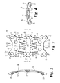
- FIG. 2 is a top plan view of the fixation plate shown in FIG. 1.
- FIG. 3 is a side cross-sectional view of the plate shown in FIG. 2, taken along line 3-3 as viewed in the direction of the arrows.
- FIG. 4 is an end cross-sectional view of the plate shown in FIG. 2, taken along line 4-4 as viewed in the direction of the arrows.
- FIG. 5 is an enlarged view of the dorsal aspect of the mid-foot with a fixation plate positioned thereon in accordance with a further embodiment of the invention.
- Referring to the drawings, FIG. 1 shows the bones of the mid-foot, along with a
fixation plate 10 in accordance with a preferred embodiment of the invention. As can be seen in the figure, theplate 10 spans between the base of the first and second metatarsal bones across to the internal (or medial) and middle cuneiforms. In the embodiment illustrated in FIG. 1, alarge plate 10 is provided that permits attachment to each of the bones of this portion of the mid-foot. - Details of the
plate 10 are shown in FIGS. 2 to 4. Theplate 10 is generally configured from abody 11 of generally uniform thickness and material composition. In the preferred embodiment, thebody 11 is formed of a biocompatible material, most preferably a metal. In a specific embodiment, the body material is titanium or a titanium alloy, such as Ti-6Al-4V. In order to reduce the prominence of theplate 10 above the bones of the mid-foot, the plate has a nominal thickness betweenupper surface 12 and boneengaging surface 13 that is minimized while still retaining sufficient strength to ensure solid fixation of the bones and joints of the mid-foot. In a preferred embodiment, the plate has a thickness of less than 1.0 mm, and most preferably about 0.9 mm. This thickness provides sufficient strength while retaining the ability to bend the plate as required to conform to the geometry of the implantation site. In particular, theplate 10 is configured to be positioned anywhere along the mid-foot, not just at the location shown in FIG. 1. Thus, geometry of the middle cuneiform may require a differently contoured plate than a plate positioned across the cuboid bone. - Preferably, however, the plate does not require any on-site contouring since the bone
engaging surface 13 is curved in two dimensions to follow the anatomy of the mid-foot, especially across the metatarsal joints. Thus, as shown in the side cross-sectional view of FIG. 3, thesurface 13, and hence theplate 10, is curved along the length of the plate. The plate is preferably curved at a uniform radius, such as about 75 mm in a specific embodiment. Similarly, the plate is curved across its width, as reflected in the end cross-sectional view of FIG. 4. This curvature is also at about 75 mm in a specific embodiment. Most preferably, the entire plate is formed at a spherical radius, which may be about 75 mm in the specific embodiment. - The
body 11 further includes end edges 15 and side edges 19. In order to reduce material requirements and minimize prominence of theplate 10, the edges defineindentations single indentation 16 that is flanked on opposite sides of the plate bycorner protrusions 17. Theseprotrusions 17 merge into theindentations 19 at the side edges 18. Acentre protrusion 20 is defined on eachside edge 18 that is preferably equidistant from each of thecorner protrusions 17. In the preferred embodiment, all of theedges - As shown in FIG. 2, each of the
protrusions screw hole 25. Each screw hole is configured to receive a bone engaging fastener configured to attach theplate 10 to the bones of the mid-foot. In the preferred embodiment, the fastener is a bone screw that is appropriately sized for implantation within the base of the metatarsus, any of the cuneiforms or the cuboid bone. The length and diameter of the screw is generally dictated by the location and the size of the bone or bone fragment being fixed. As shown in FIG. 2, theplate 10 includes additional screw holes 26 within the interior of the plate. These screw holes 26 increase the versatility of theplate 10 to provide additional attachment points to a given bone, or to provide a path for fixation of a bone segment, such as in the case of a severe fracture. - The
plate 10 of the present invention is specifically configured for implantation and fixation of the mid-foot. Thus, the plate is sized so that the screw holes 25, 26 are optimally positioned for correction and arthrodesis of numerous mid-foot injuries. In a specific embodiment, the plate has a width dimension of about 21.5 mm between the screw holes in thecorner protrusions 17 andintermediate protrusions 20. The interior screw holes 26 are preferably at a width dimension of about 10.0 mm. Theplate 10 has a length between screw holes 25 at the corner protrusions of about 36.8 mm. - The screw holes 25, 26 are formed at a diameter commensurate with the size of the bone screw used to attach the plate to bone. In the preferred embodiment, the screw holes are configured for 2.7 mm or 3.5 mm screws that are commonly used for fixation of the bones of the foot. In one feature of the invention, the screw holes may include a circumferential chamfer, such as the
chamfer 53 for the screw holes 52 of theplate 50 shown in FIG. 5. This configuration of the screw holes allows the plate to accept either size screw at any screw hole location. The present invention further contemplates that the screws may be non-locking or self-locking screws, with the screw holes configured accordingly. In a specific embodiment, locking screws are used and the screw holes 25, 26 define tapered threads (not shown) of conventional design. - A further feature of the invention is best seen in FIG. 2. In particular, the
body 11 of the plate defines a plurality of cut-outs, including two cut-outs 32 on each side and two central cut-outs 30, for a total of six cut-outs. The cut-outs plate 10. In addition, the cut-outs createopposite end portions 34 and acentre portion 36 spanned bystruts centre portions struts portions struts outs 30 are triangular in shape, while the side cut-outs 32 are generally trapezoidal or rectangular in shape. The cut-outs - In addition to reducing the plate material, the cut-
outs outs outs 30 are especially sized to accept a standard bone screw for fixation of mid-foot bone fragments. - In order to facilitate proper placement of the
plate 10, asmall diameter hole 28 is defined at the centre of theplate 10 in thecentre portion 36. Thehole 28 is preferably sized to receive a K-wire or other similar guide wire. In an exemplary procedure for correction of a Lisfranc fracture/dislocation, a K-wire may be inserted into the middle cuneiform to guide theplate 10 across the metatarsus-cuneiform spaces. In one aspect of the invention, theplate 10 provides for screw placement around the perimeter of the mid-foot segments to be fused, in particular with screws placed in the screw holes 25 at theprotrusions outs outs - For a smaller mid-foot anatomy or a smaller fusion region, the
plate 10 may be modified to form asmaller plate 50, as shown in FIG. 5. This smaller plate retains the spherical curvature and minimal plate thickness described above in connection with thelarger plate 10. In addition, theplate 50 includes thecorner protrusions 51 which carry the screw holes 52. Screw holes 54 may be provided at the interior of theplate 50 to increase the versatility of the plate. A K-wire hole 56 may also be provided at the centre of the plate. Thesmaller plate 50 is preferably adapted for patients with smaller mid-foot bone and joint structure. - In the preferred embodiment of the invention, a fixation device is in the form of the
plate 10 having a plurality of screw holes for attachment of the plate around the perimeter of the fusion site. In the most preferred embodiment, four screw holes are positioned at the corners of the plate with two screw holes at the opposite sides and mid-length of the plate. Preferably, four additional screw holes are defined at the interior of the plate to increase the number of points of attachment of the plate to the bones of the mid-foot or to increase the ability to stabilize multiple bone segments in the case of a difficult mid-foot fracture. In yet another feature of the preferred embodiment, a plurality of cut-outs are defined in the plate between or interior of the screw holes. In the most preferred embodiment, two generally triangular cut-outs are positioned along the longitudinal axis of the plate inboard of the interior screw holes, and four larger cut-outs surround the triangular cut-outs, but still fall within the perimeter defined by the screw holes.
Claims (12)
- A fixation device for fusion of bones or bone segments in the human mid-foot, comprising:a plate sized for implantation within the mid-foot of a patient, said plate defining a plurality of holes, each having a diameter sized for receiving a bone engaging fastener for attachment of said plate to bone or bone segments of the mid-foot; andsaid plate further defining a plurality of cut-outs, each dimensioned greater than the diameter of said plurality of holes.
- The fixation device of claim 1, wherein said plate has a substantially uniform thickness less than about 1.0mm.
- The fixation device of claim 1, wherein said plurality of screw holes include a circumferential chamfer so the screw holes can receive different sizes of fasteners.
- The fixation device of claim 1, wherein said plurality of holes are arranged around the perimeter of said plate.
- The fixation device of claim 4, wherein said plurality of cut-outs are arranged inboard of each of said plurality of holes.
- The fixation device of claim 1, wherein said plurality of cut-outs includes a pair of triangular shaped cut-outs arranged along a longitudinal axis of said plate.
- The fixation device of claim 1, wherein said plurality of cut-outs includes two cut-outs adjacent each side of said plate.
- The fixation device of claim 7, wherein said two cut-outs adjacent each side are trapezoidal or substantially rectangular in shape.
- The fixation device of claim 1, wherein said plate further defines a guide wire hole sized to receive a guide wire or K-wire.
- The fixation device of claim 9, wherein said guide wire hole is disposed substantially in the centre of said plate.
- The fixation device of claim 1, wherein the edges of said plate define a plurality of indentations and protrusions in which at least some of the plurality of holes is defined in a corresponding one of said protrusions.
- The fixation device of claim 1, wherein said plate includes a bone engaging surface that is curved at a substantially uniform spherical radius.
Applications Claiming Priority (1)
| Application Number | Priority Date | Filing Date | Title |
|---|---|---|---|
| US11/094,994 US7344538B2 (en) | 2005-03-31 | 2005-03-31 | Mid-foot fixation plate |
Publications (2)
| Publication Number | Publication Date |
|---|---|
| EP1707139A1 true EP1707139A1 (en) | 2006-10-04 |
| EP1707139B1 EP1707139B1 (en) | 2010-04-21 |
Family
ID=36608642
Family Applications (1)
| Application Number | Title | Priority Date | Filing Date |
|---|---|---|---|
| EP06251809A Not-in-force EP1707139B1 (en) | 2005-03-31 | 2006-03-31 | Mid-foot fixation plate |
Country Status (6)
| Country | Link |
|---|---|
| US (1) | US7344538B2 (en) |
| EP (1) | EP1707139B1 (en) |
| JP (1) | JP5079251B2 (en) |
| AT (1) | ATE464849T1 (en) |
| AU (1) | AU2006201319B2 (en) |
| DE (1) | DE602006013738D1 (en) |
Cited By (3)
| Publication number | Priority date | Publication date | Assignee | Title |
|---|---|---|---|---|
| CN102755186A (en) * | 2012-07-26 | 2012-10-31 | 徐仲棉 | Special anatomic locking bone plate for peripherical joint fusion of foot bone and talus |
| CN104546102A (en) * | 2015-01-12 | 2015-04-29 | 常州华森医疗器械有限公司 | Lisfrance joint injury fusion plate |
| CN105030315A (en) * | 2015-08-24 | 2015-11-11 | 苏州市康力骨科器械有限公司 | Steel plate for locking foot bone in multidirectional mode |
Families Citing this family (52)
| Publication number | Priority date | Publication date | Assignee | Title |
|---|---|---|---|---|
| US8246663B2 (en) * | 2006-04-10 | 2012-08-21 | Scott Lovald | Osteosynthesis plate, method of customizing same, and method for installing same |
| US7901431B2 (en) * | 2007-01-17 | 2011-03-08 | Arthrex, Inc. | Lisfranc repair using suture-button construct |
| SE531177C2 (en) | 2007-05-24 | 2009-01-13 | Cochlear Ltd | Distance for implants |
| US8167918B2 (en) * | 2008-02-19 | 2012-05-01 | Orthohelix Surgical Designs, Inc. | Orthopedic plate for use in the MTP joint |
| US8257406B2 (en) * | 2008-02-19 | 2012-09-04 | Orthohelix Surgical Designs, Inc. | Orthopedic plate for use on a single ray in the midfoot |
| US8257403B2 (en) * | 2008-02-19 | 2012-09-04 | Orthohelix Surgical Designs, Inc. | Orthopedic plate for use in the midfoot |
| EP2326263B1 (en) | 2008-05-30 | 2019-02-27 | Wright Medical Technology, Inc. | Drill guide assembly |
| US8303589B2 (en) * | 2008-06-24 | 2012-11-06 | Extremity Medical Llc | Fixation system, an intramedullary fixation assembly and method of use |
| US9289220B2 (en) | 2008-06-24 | 2016-03-22 | Extremity Medical Llc | Intramedullary fixation assembly and method of use |
| US9044282B2 (en) * | 2008-06-24 | 2015-06-02 | Extremity Medical Llc | Intraosseous intramedullary fixation assembly and method of use |
| US8313487B2 (en) | 2008-06-24 | 2012-11-20 | Extremity Medical Llc | Fixation system, an intramedullary fixation assembly and method of use |
| US20100121325A1 (en) * | 2008-06-24 | 2010-05-13 | Jeff Tyber | Hybrid intramedullary fixation assembly and method of use |
| US9017329B2 (en) * | 2008-06-24 | 2015-04-28 | Extremity Medical, Llc | Intramedullary fixation assembly and method of use |
| US20110230884A1 (en) * | 2008-06-24 | 2011-09-22 | Adam Mantzaris | Hybrid intramedullary fixation assembly and method of use |
| US8343199B2 (en) * | 2008-06-24 | 2013-01-01 | Extremity Medical, Llc | Intramedullary fixation screw, a fixation system, and method of fixation of the subtalar joint |
| US8328806B2 (en) * | 2008-06-24 | 2012-12-11 | Extremity Medical, Llc | Fixation system, an intramedullary fixation assembly and method of use |
| FR2936700B1 (en) * | 2008-10-02 | 2012-04-13 | Memometal Technologies | ORTHOPEDIC IMPLANT IN THE FORM OF A PLATE TO BE FIXED BETWEEN TWO BONE PARTS |
| US8828063B2 (en) | 2008-11-19 | 2014-09-09 | Amei Technologies, Inc. | Fixation plate for use in the Lapidus approach |
| US20100198266A1 (en) * | 2009-02-05 | 2010-08-05 | Paul Fuad Nassab | Biplanar Fracture Fixation |
| US8246664B2 (en) | 2009-02-24 | 2012-08-21 | Osteomed Llc | Multiple bone fusion plate |
| US8529608B2 (en) | 2009-04-28 | 2013-09-10 | Osteomed Llc | Bone plate with a transfixation screw hole |
| FR2951072B1 (en) | 2009-10-13 | 2011-11-18 | Biotech Internat | SCAPHO-LUNAR STABILIZATION IMPLANT |
| US8535355B2 (en) * | 2009-10-15 | 2013-09-17 | Biomet C.V. | Dorsal midfoot bone plate system and method |
| US8551107B2 (en) | 2009-10-15 | 2013-10-08 | Biomet, C.V. | Bending tool and method for reshaping a bone plate |
| US20130018424A1 (en) * | 2011-07-13 | 2013-01-17 | Michael Subik | Osteotomy and arthrodesis treatment system |
| US8998904B2 (en) | 2012-07-17 | 2015-04-07 | Fastforward Surgical Inc. | Winged tether plate and method of use for reducing angular bone deformity |
| US9220597B2 (en) * | 2013-02-12 | 2015-12-29 | Ossdsign Ab | Mosaic implants, kits and methods for correcting bone defects |
| US9358053B2 (en) * | 2013-03-01 | 2016-06-07 | Stryker European Holdings I, Llc | Pelvic bone plate |
| EP3021773B1 (en) | 2013-07-16 | 2018-11-07 | Fastforward Surgical Inc. | Bone plate for reducing angular bone deformity |
| WO2016112178A1 (en) | 2015-01-07 | 2016-07-14 | Treace Medical Concepts, Inc. | Bone plating system and method |
| US10245086B2 (en) | 2015-02-18 | 2019-04-02 | Treace Medical Concepts, Inc. | Bone plating kit for foot and ankle applications |
| US20170000533A1 (en) | 2015-07-02 | 2017-01-05 | First Ray, LLC | Compression implants, instruments and methods |
| US10130402B2 (en) | 2015-09-25 | 2018-11-20 | Globus Medical, Inc. | Bone fixation devices having a locking feature |
| US10702290B2 (en) | 2015-11-02 | 2020-07-07 | First Ray, LLC | Orthopedic fastener, retainer, and guide |
| US9974581B2 (en) | 2015-11-20 | 2018-05-22 | Globus Medical, Inc. | Expandable intramedullary systems and methods of using the same |
| EP3380046B1 (en) | 2015-11-24 | 2021-07-14 | OssDsign AB | Bone implants and methods for correcting bone defects |
| US9795411B2 (en) | 2016-03-02 | 2017-10-24 | Globus Medical, Inc. | Fixators for bone stabilization and associated systems and methods |
| US10531905B2 (en) | 2016-04-19 | 2020-01-14 | Globus Medical, Inc. | Implantable compression screws |
| US10172645B2 (en) | 2016-05-20 | 2019-01-08 | Fastforward Surgical Inc. | Method of correcting hallux varus joint deformity |
| US11432857B2 (en) | 2016-08-17 | 2022-09-06 | Globus Medical, Inc. | Stabilization systems |
| US11197701B2 (en) | 2016-08-17 | 2021-12-14 | Globus Medical, Inc. | Stabilization systems |
| US11033333B2 (en) | 2017-04-06 | 2021-06-15 | Stryker European Holdings I, Llc | Plate selection user interface and design tool with database |
| EP3424452B1 (en) | 2017-06-16 | 2024-03-13 | Stryker European Operations Holdings LLC | Patient-specific bridging plates |
| US11224468B2 (en) | 2018-03-02 | 2022-01-18 | Globus Medical, Inc. | Distal tibial plating system |
| US11071570B2 (en) | 2018-03-02 | 2021-07-27 | Globus Medical, Inc. | Distal tibial plating system |
| US11141172B2 (en) | 2018-04-11 | 2021-10-12 | Globus Medical, Inc. | Method and apparatus for locking a drill guide in a polyaxial hole |
| US11583323B2 (en) | 2018-07-12 | 2023-02-21 | Treace Medical Concepts, Inc. | Multi-diameter bone pin for installing and aligning bone fixation plate while minimizing bone damage |
| US10849665B2 (en) | 2018-10-29 | 2020-12-01 | Stryker European Operations Holdings Llc | Snap-fit cutting guides and plating systems |
| US11202663B2 (en) | 2019-02-13 | 2021-12-21 | Globus Medical, Inc. | Proximal humeral stabilization systems and methods thereof |
| US11890039B1 (en) | 2019-09-13 | 2024-02-06 | Treace Medical Concepts, Inc. | Multi-diameter K-wire for orthopedic applications |
| US11129627B2 (en) | 2019-10-30 | 2021-09-28 | Globus Medical, Inc. | Method and apparatus for inserting a bone plate |
| US11723647B2 (en) | 2019-12-17 | 2023-08-15 | Globus Medical, Inc. | Syndesmosis fixation assembly |
Citations (5)
| Publication number | Priority date | Publication date | Assignee | Title |
|---|---|---|---|---|
| US6344042B1 (en) * | 1998-05-12 | 2002-02-05 | Synthes (Usa) | Bone augmentation device |
| US20020128654A1 (en) | 1998-02-18 | 2002-09-12 | Steger Shon D. | Method and apparatus for bone fracture fixation |
| US20040102778A1 (en) * | 2002-11-19 | 2004-05-27 | Huebner Randall J. | Adjustable bone plates |
| US20040102775A1 (en) * | 2002-11-19 | 2004-05-27 | Huebner Randall J. | Bone plates with slots |
| US20050065521A1 (en) * | 2002-02-22 | 2005-03-24 | Steger Shon D. | Method and apparatus for bone fracture fixation |
Family Cites Families (15)
| Publication number | Priority date | Publication date | Assignee | Title |
|---|---|---|---|---|
| GB1579575A (en) * | 1977-04-06 | 1980-11-19 | English Biomechanics Ltd T A | Implants |
| US4905679A (en) * | 1988-02-22 | 1990-03-06 | M P Operation, Inc. | Bone fracture reduction device and method of internal fixation of bone fractures |
| DE69837626T2 (en) * | 1997-02-11 | 2007-12-20 | Warsaw Orthopedic, Inc., Warsaw | Plate with locking mechanism for the anterior cervical spine |
| US5752958A (en) * | 1997-04-02 | 1998-05-19 | Wellisz; Tadeusz Z. | Bone fixation plate |
| ZA983955B (en) * | 1997-05-15 | 2001-08-13 | Sdgi Holdings Inc | Anterior cervical plating system. |
| US6129730A (en) * | 1999-02-10 | 2000-10-10 | Depuy Acromed, Inc. | Bi-fed offset pitch bone screw |
| US6221073B1 (en) * | 1999-08-20 | 2001-04-24 | Kinetikos Medical, Inc. | Wrist fusion apparatus and method |
| TW499953U (en) * | 2000-12-19 | 2002-08-21 | Jr-Yi Lin | Spine fastening reposition device |
| US6599290B2 (en) * | 2001-04-17 | 2003-07-29 | Ebi, L.P. | Anterior cervical plating system and associated method |
| WO2003013623A1 (en) * | 2001-08-10 | 2003-02-20 | Osteotech, Inc. | Bone plating system and method of use |
| FR2829920B1 (en) * | 2001-09-26 | 2004-05-28 | Newdeal Sa | PLATE FOR FIXING THE BONES OF A JOINT, PARTICULARLY A METATARSO-PHALANGIAN JOINT |
| US6679883B2 (en) * | 2001-10-31 | 2004-01-20 | Ortho Development Corporation | Cervical plate for stabilizing the human spine |
| US7179260B2 (en) * | 2003-09-29 | 2007-02-20 | Smith & Nephew, Inc. | Bone plates and bone plate assemblies |
| FR2848413B1 (en) * | 2002-12-11 | 2005-07-29 | Fixano | OSTEOSYNTHESIS PLATE FOR OSTEOSYNTHESIS OF SMALL BONE NEIGHBORS OF OTHERS |
| US20060025772A1 (en) * | 2004-07-30 | 2006-02-02 | Leibel David A | Bone fusion plate |
-
2005
- 2005-03-31 US US11/094,994 patent/US7344538B2/en not_active Expired - Fee Related
-
2006
- 2006-03-29 AU AU2006201319A patent/AU2006201319B2/en not_active Ceased
- 2006-03-30 JP JP2006094526A patent/JP5079251B2/en not_active Expired - Fee Related
- 2006-03-31 AT AT06251809T patent/ATE464849T1/en not_active IP Right Cessation
- 2006-03-31 DE DE602006013738T patent/DE602006013738D1/en active Active
- 2006-03-31 EP EP06251809A patent/EP1707139B1/en not_active Not-in-force
Patent Citations (5)
| Publication number | Priority date | Publication date | Assignee | Title |
|---|---|---|---|---|
| US20020128654A1 (en) | 1998-02-18 | 2002-09-12 | Steger Shon D. | Method and apparatus for bone fracture fixation |
| US6344042B1 (en) * | 1998-05-12 | 2002-02-05 | Synthes (Usa) | Bone augmentation device |
| US20050065521A1 (en) * | 2002-02-22 | 2005-03-24 | Steger Shon D. | Method and apparatus for bone fracture fixation |
| US20040102778A1 (en) * | 2002-11-19 | 2004-05-27 | Huebner Randall J. | Adjustable bone plates |
| US20040102775A1 (en) * | 2002-11-19 | 2004-05-27 | Huebner Randall J. | Bone plates with slots |
Cited By (3)
| Publication number | Priority date | Publication date | Assignee | Title |
|---|---|---|---|---|
| CN102755186A (en) * | 2012-07-26 | 2012-10-31 | 徐仲棉 | Special anatomic locking bone plate for peripherical joint fusion of foot bone and talus |
| CN104546102A (en) * | 2015-01-12 | 2015-04-29 | 常州华森医疗器械有限公司 | Lisfrance joint injury fusion plate |
| CN105030315A (en) * | 2015-08-24 | 2015-11-11 | 苏州市康力骨科器械有限公司 | Steel plate for locking foot bone in multidirectional mode |
Also Published As
| Publication number | Publication date |
|---|---|
| DE602006013738D1 (en) | 2010-06-02 |
| ATE464849T1 (en) | 2010-05-15 |
| JP5079251B2 (en) | 2012-11-21 |
| EP1707139B1 (en) | 2010-04-21 |
| JP2006280949A (en) | 2006-10-19 |
| AU2006201319B2 (en) | 2011-01-27 |
| US7344538B2 (en) | 2008-03-18 |
| AU2006201319A1 (en) | 2006-10-19 |
| US20060241592A1 (en) | 2006-10-26 |
Similar Documents
| Publication | Publication Date | Title |
|---|---|---|
| EP1707139B1 (en) | Mid-foot fixation plate | |
| US11896270B2 (en) | Systems and methods for using polyaxial plates | |
| US20240090928A1 (en) | Systems and methods for using polyaxial plates | |
| JP5079250B2 (en) | Scaphoid fixation device | |
| EP1507486B1 (en) | Intramedullary fixation device for metaphyseal long bone fractures | |
| EP1707142B1 (en) | Metatarsal fixation plate | |
| US6096040A (en) | Upper extremity bone plates | |
| US7686808B2 (en) | Fracture fixation device and implantation jig therefor | |
| US6123709A (en) | Bone buttress plate and method of using same | |
| EP1707227A2 (en) | Plate for fusion of the metatarso-phalangeal joint | |
| US20060161156A1 (en) | Fracture fixation device | |
| WO1997047251A9 (en) | Upper extremity bone plate | |
| US20060149257A1 (en) | Fracture fixation device | |
| IL193043A (en) | Fracture fixation device and implantation jig therefor | |
| AU2003234384B2 (en) | Intramedullary fixation device for metaphyseal long bone fractures |
Legal Events
| Date | Code | Title | Description |
|---|---|---|---|
| PUAI | Public reference made under article 153(3) epc to a published international application that has entered the european phase |
Free format text: ORIGINAL CODE: 0009012 |
|
| AK | Designated contracting states |
Kind code of ref document: A1 Designated state(s): AT BE BG CH CY CZ DE DK EE ES FI FR GB GR HU IE IS IT LI LT LU LV MC NL PL PT RO SE SI SK TR |
|
| AX | Request for extension of the european patent |
Extension state: AL BA HR MK YU |
|
| 17P | Request for examination filed |
Effective date: 20070302 |
|
| 17Q | First examination report despatched |
Effective date: 20070329 |
|
| AKX | Designation fees paid |
Designated state(s): AT BE BG CH CY CZ DE DK EE ES FI FR GB GR HU IE IS IT LI LT LU LV MC NL PL PT RO SE SI SK TR |
|
| GRAP | Despatch of communication of intention to grant a patent |
Free format text: ORIGINAL CODE: EPIDOSNIGR1 |
|
| GRAS | Grant fee paid |
Free format text: ORIGINAL CODE: EPIDOSNIGR3 |
|
| GRAA | (expected) grant |
Free format text: ORIGINAL CODE: 0009210 |
|
| AK | Designated contracting states |
Kind code of ref document: B1 Designated state(s): AT BE BG CH CY CZ DE DK EE ES FI FR GB GR HU IE IS IT LI LT LU LV MC NL PL PT RO SE SI SK TR |
|
| REG | Reference to a national code |
Ref country code: GB Ref legal event code: FG4D |
|
| REG | Reference to a national code |
Ref country code: CH Ref legal event code: EP Ref country code: CH Ref legal event code: NV Representative=s name: E. BLUM & CO. AG PATENT- UND MARKENANWAELTE VSP |
|
| REG | Reference to a national code |
Ref country code: IE Ref legal event code: FG4D |
|
| REF | Corresponds to: |
Ref document number: 602006013738 Country of ref document: DE Date of ref document: 20100602 Kind code of ref document: P |
|
| REG | Reference to a national code |
Ref country code: NL Ref legal event code: VDEP Effective date: 20100421 |
|
| LTIE | Lt: invalidation of european patent or patent extension |
Effective date: 20100421 |
|
| PG25 | Lapsed in a contracting state [announced via postgrant information from national office to epo] |
Ref country code: SE Free format text: LAPSE BECAUSE OF FAILURE TO SUBMIT A TRANSLATION OF THE DESCRIPTION OR TO PAY THE FEE WITHIN THE PRESCRIBED TIME-LIMIT Effective date: 20100421 Ref country code: ES Free format text: LAPSE BECAUSE OF FAILURE TO SUBMIT A TRANSLATION OF THE DESCRIPTION OR TO PAY THE FEE WITHIN THE PRESCRIBED TIME-LIMIT Effective date: 20100801 Ref country code: LT Free format text: LAPSE BECAUSE OF FAILURE TO SUBMIT A TRANSLATION OF THE DESCRIPTION OR TO PAY THE FEE WITHIN THE PRESCRIBED TIME-LIMIT Effective date: 20100421 Ref country code: NL Free format text: LAPSE BECAUSE OF FAILURE TO SUBMIT A TRANSLATION OF THE DESCRIPTION OR TO PAY THE FEE WITHIN THE PRESCRIBED TIME-LIMIT Effective date: 20100421 |
|
| PG25 | Lapsed in a contracting state [announced via postgrant information from national office to epo] |
Ref country code: AT Free format text: LAPSE BECAUSE OF FAILURE TO SUBMIT A TRANSLATION OF THE DESCRIPTION OR TO PAY THE FEE WITHIN THE PRESCRIBED TIME-LIMIT Effective date: 20100421 Ref country code: SI Free format text: LAPSE BECAUSE OF FAILURE TO SUBMIT A TRANSLATION OF THE DESCRIPTION OR TO PAY THE FEE WITHIN THE PRESCRIBED TIME-LIMIT Effective date: 20100421 Ref country code: LV Free format text: LAPSE BECAUSE OF FAILURE TO SUBMIT A TRANSLATION OF THE DESCRIPTION OR TO PAY THE FEE WITHIN THE PRESCRIBED TIME-LIMIT Effective date: 20100421 Ref country code: IS Free format text: LAPSE BECAUSE OF FAILURE TO SUBMIT A TRANSLATION OF THE DESCRIPTION OR TO PAY THE FEE WITHIN THE PRESCRIBED TIME-LIMIT Effective date: 20100821 Ref country code: FI Free format text: LAPSE BECAUSE OF FAILURE TO SUBMIT A TRANSLATION OF THE DESCRIPTION OR TO PAY THE FEE WITHIN THE PRESCRIBED TIME-LIMIT Effective date: 20100421 |
|
| PG25 | Lapsed in a contracting state [announced via postgrant information from national office to epo] |
Ref country code: CY Free format text: LAPSE BECAUSE OF FAILURE TO SUBMIT A TRANSLATION OF THE DESCRIPTION OR TO PAY THE FEE WITHIN THE PRESCRIBED TIME-LIMIT Effective date: 20100505 Ref country code: GR Free format text: LAPSE BECAUSE OF FAILURE TO SUBMIT A TRANSLATION OF THE DESCRIPTION OR TO PAY THE FEE WITHIN THE PRESCRIBED TIME-LIMIT Effective date: 20100722 Ref country code: PL Free format text: LAPSE BECAUSE OF FAILURE TO SUBMIT A TRANSLATION OF THE DESCRIPTION OR TO PAY THE FEE WITHIN THE PRESCRIBED TIME-LIMIT Effective date: 20100421 |
|
| PG25 | Lapsed in a contracting state [announced via postgrant information from national office to epo] |
Ref country code: EE Free format text: LAPSE BECAUSE OF FAILURE TO SUBMIT A TRANSLATION OF THE DESCRIPTION OR TO PAY THE FEE WITHIN THE PRESCRIBED TIME-LIMIT Effective date: 20100421 Ref country code: DK Free format text: LAPSE BECAUSE OF FAILURE TO SUBMIT A TRANSLATION OF THE DESCRIPTION OR TO PAY THE FEE WITHIN THE PRESCRIBED TIME-LIMIT Effective date: 20100421 Ref country code: PT Free format text: LAPSE BECAUSE OF FAILURE TO SUBMIT A TRANSLATION OF THE DESCRIPTION OR TO PAY THE FEE WITHIN THE PRESCRIBED TIME-LIMIT Effective date: 20100823 |
|
| PLBE | No opposition filed within time limit |
Free format text: ORIGINAL CODE: 0009261 |
|
| STAA | Information on the status of an ep patent application or granted ep patent |
Free format text: STATUS: NO OPPOSITION FILED WITHIN TIME LIMIT |
|
| PG25 | Lapsed in a contracting state [announced via postgrant information from national office to epo] |
Ref country code: BE Free format text: LAPSE BECAUSE OF FAILURE TO SUBMIT A TRANSLATION OF THE DESCRIPTION OR TO PAY THE FEE WITHIN THE PRESCRIBED TIME-LIMIT Effective date: 20100421 Ref country code: SK Free format text: LAPSE BECAUSE OF FAILURE TO SUBMIT A TRANSLATION OF THE DESCRIPTION OR TO PAY THE FEE WITHIN THE PRESCRIBED TIME-LIMIT Effective date: 20100421 Ref country code: RO Free format text: LAPSE BECAUSE OF FAILURE TO SUBMIT A TRANSLATION OF THE DESCRIPTION OR TO PAY THE FEE WITHIN THE PRESCRIBED TIME-LIMIT Effective date: 20100421 Ref country code: CZ Free format text: LAPSE BECAUSE OF FAILURE TO SUBMIT A TRANSLATION OF THE DESCRIPTION OR TO PAY THE FEE WITHIN THE PRESCRIBED TIME-LIMIT Effective date: 20100421 |
|
| 26N | No opposition filed |
Effective date: 20110124 |
|
| PG25 | Lapsed in a contracting state [announced via postgrant information from national office to epo] |
Ref country code: MC Free format text: LAPSE BECAUSE OF NON-PAYMENT OF DUE FEES Effective date: 20110331 |
|
| REG | Reference to a national code |
Ref country code: IE Ref legal event code: MM4A |
|
| PG25 | Lapsed in a contracting state [announced via postgrant information from national office to epo] |
Ref country code: IE Free format text: LAPSE BECAUSE OF NON-PAYMENT OF DUE FEES Effective date: 20110331 |
|
| PG25 | Lapsed in a contracting state [announced via postgrant information from national office to epo] |
Ref country code: LU Free format text: LAPSE BECAUSE OF NON-PAYMENT OF DUE FEES Effective date: 20110331 |
|
| PG25 | Lapsed in a contracting state [announced via postgrant information from national office to epo] |
Ref country code: BG Free format text: LAPSE BECAUSE OF FAILURE TO SUBMIT A TRANSLATION OF THE DESCRIPTION OR TO PAY THE FEE WITHIN THE PRESCRIBED TIME-LIMIT Effective date: 20100721 Ref country code: TR Free format text: LAPSE BECAUSE OF FAILURE TO SUBMIT A TRANSLATION OF THE DESCRIPTION OR TO PAY THE FEE WITHIN THE PRESCRIBED TIME-LIMIT Effective date: 20100421 |
|
| PG25 | Lapsed in a contracting state [announced via postgrant information from national office to epo] |
Ref country code: HU Free format text: LAPSE BECAUSE OF FAILURE TO SUBMIT A TRANSLATION OF THE DESCRIPTION OR TO PAY THE FEE WITHIN THE PRESCRIBED TIME-LIMIT Effective date: 20100421 |
|
| REG | Reference to a national code |
Ref country code: FR Ref legal event code: PLFP Year of fee payment: 11 |
|
| REG | Reference to a national code |
Ref country code: FR Ref legal event code: TP Owner name: BIOMET C.V., GI Effective date: 20160818 |
|
| REG | Reference to a national code |
Ref country code: FR Ref legal event code: PLFP Year of fee payment: 12 |
|
| PGFP | Annual fee paid to national office [announced via postgrant information from national office to epo] |
Ref country code: CH Payment date: 20170314 Year of fee payment: 12 Ref country code: FR Payment date: 20170213 Year of fee payment: 12 |
|
| PGFP | Annual fee paid to national office [announced via postgrant information from national office to epo] |
Ref country code: GB Payment date: 20170329 Year of fee payment: 12 |
|
| PGFP | Annual fee paid to national office [announced via postgrant information from national office to epo] |
Ref country code: IT Payment date: 20170320 Year of fee payment: 12 |
|
| REG | Reference to a national code |
Ref country code: CH Ref legal event code: PL |
|
| GBPC | Gb: european patent ceased through non-payment of renewal fee |
Effective date: 20180331 |
|
| PGFP | Annual fee paid to national office [announced via postgrant information from national office to epo] |
Ref country code: DE Payment date: 20181001 Year of fee payment: 13 |
|
| PG25 | Lapsed in a contracting state [announced via postgrant information from national office to epo] |
Ref country code: LI Free format text: LAPSE BECAUSE OF NON-PAYMENT OF DUE FEES Effective date: 20180331 Ref country code: CH Free format text: LAPSE BECAUSE OF NON-PAYMENT OF DUE FEES Effective date: 20180331 Ref country code: IT Free format text: LAPSE BECAUSE OF NON-PAYMENT OF DUE FEES Effective date: 20180331 Ref country code: GB Free format text: LAPSE BECAUSE OF NON-PAYMENT OF DUE FEES Effective date: 20180331 |
|
| PG25 | Lapsed in a contracting state [announced via postgrant information from national office to epo] |
Ref country code: FR Free format text: LAPSE BECAUSE OF NON-PAYMENT OF DUE FEES Effective date: 20180331 |
|
| REG | Reference to a national code |
Ref country code: DE Ref legal event code: R119 Ref document number: 602006013738 Country of ref document: DE |
|
| PG25 | Lapsed in a contracting state [announced via postgrant information from national office to epo] |
Ref country code: DE Free format text: LAPSE BECAUSE OF NON-PAYMENT OF DUE FEES Effective date: 20191001 |