EP1707105A1 - In vivo imaging device and method of manufacture thereof - Google Patents
In vivo imaging device and method of manufacture thereof Download PDFInfo
- Publication number
- EP1707105A1 EP1707105A1 EP06111769A EP06111769A EP1707105A1 EP 1707105 A1 EP1707105 A1 EP 1707105A1 EP 06111769 A EP06111769 A EP 06111769A EP 06111769 A EP06111769 A EP 06111769A EP 1707105 A1 EP1707105 A1 EP 1707105A1
- Authority
- EP
- European Patent Office
- Prior art keywords
- antenna
- imaging device
- vivo imaging
- circuit board
- isolation element
- Prior art date
- Legal status (The legal status is an assumption and is not a legal conclusion. Google has not performed a legal analysis and makes no representation as to the accuracy of the status listed.)
- Withdrawn
Links
Images


Classifications
-
- A—HUMAN NECESSITIES
- A61—MEDICAL OR VETERINARY SCIENCE; HYGIENE
- A61B—DIAGNOSIS; SURGERY; IDENTIFICATION
- A61B1/00—Instruments for performing medical examinations of the interior of cavities or tubes of the body by visual or photographical inspection, e.g. endoscopes; Illuminating arrangements therefor
- A61B1/04—Instruments for performing medical examinations of the interior of cavities or tubes of the body by visual or photographical inspection, e.g. endoscopes; Illuminating arrangements therefor combined with photographic or television appliances
- A61B1/042—Instruments for performing medical examinations of the interior of cavities or tubes of the body by visual or photographical inspection, e.g. endoscopes; Illuminating arrangements therefor combined with photographic or television appliances characterised by a proximal camera, e.g. a CCD camera
-
- A—HUMAN NECESSITIES
- A61—MEDICAL OR VETERINARY SCIENCE; HYGIENE
- A61B—DIAGNOSIS; SURGERY; IDENTIFICATION
- A61B1/00—Instruments for performing medical examinations of the interior of cavities or tubes of the body by visual or photographical inspection, e.g. endoscopes; Illuminating arrangements therefor
- A61B1/00064—Constructional details of the endoscope body
- A61B1/0011—Manufacturing of endoscope parts
-
- A—HUMAN NECESSITIES
- A61—MEDICAL OR VETERINARY SCIENCE; HYGIENE
- A61B—DIAGNOSIS; SURGERY; IDENTIFICATION
- A61B1/00—Instruments for performing medical examinations of the interior of cavities or tubes of the body by visual or photographical inspection, e.g. endoscopes; Illuminating arrangements therefor
- A61B1/04—Instruments for performing medical examinations of the interior of cavities or tubes of the body by visual or photographical inspection, e.g. endoscopes; Illuminating arrangements therefor combined with photographic or television appliances
- A61B1/041—Capsule endoscopes for imaging
-
- A—HUMAN NECESSITIES
- A61—MEDICAL OR VETERINARY SCIENCE; HYGIENE
- A61B—DIAGNOSIS; SURGERY; IDENTIFICATION
- A61B5/00—Measuring for diagnostic purposes; Identification of persons
- A61B5/07—Endoradiosondes
- A61B5/073—Intestinal transmitters
-
- H—ELECTRICITY
- H04—ELECTRIC COMMUNICATION TECHNIQUE
- H04N—PICTORIAL COMMUNICATION, e.g. TELEVISION
- H04N23/00—Cameras or camera modules comprising electronic image sensors; Control thereof
- H04N23/50—Constructional details
- H04N23/555—Constructional details for picking-up images in sites, inaccessible due to their dimensions or hazardous conditions, e.g. endoscopes or borescopes
-
- H—ELECTRICITY
- H04—ELECTRIC COMMUNICATION TECHNIQUE
- H04N—PICTORIAL COMMUNICATION, e.g. TELEVISION
- H04N7/00—Television systems
- H04N7/18—Closed-circuit television [CCTV] systems, i.e. systems in which the video signal is not broadcast
- H04N7/183—Closed-circuit television [CCTV] systems, i.e. systems in which the video signal is not broadcast for receiving images from a single remote source
-
- A—HUMAN NECESSITIES
- A61—MEDICAL OR VETERINARY SCIENCE; HYGIENE
- A61B—DIAGNOSIS; SURGERY; IDENTIFICATION
- A61B5/00—Measuring for diagnostic purposes; Identification of persons
- A61B5/0002—Remote monitoring of patients using telemetry, e.g. transmission of vital signals via a communication network
- A61B5/0004—Remote monitoring of patients using telemetry, e.g. transmission of vital signals via a communication network characterised by the type of physiological signal transmitted
- A61B5/0013—Medical image data
Definitions
- the present invention relates generally to in vivo imaging devices, and more specifically to an in-vivo imaging device with a spherical, ellipsoidal, oval, or similar shape.
- Devices and methods for performing in-vivo imaging of passages or cavities within a body are known in the art. Such devices may include, inter alia, various endoscopic imaging systems and devices for performing imaging in various internal body cavities. Some of these devices use a wireless connection to transmit image data.
- a first factor may be the size of the circuitry connected to the imaging sensor portion of the imaging device.
- a second factor may be the cumulative widths of the several components of the imaging device.
- Another factor limiting the size reduction or space usage in imaging devices may be the size of the antenna for transmitting (and/or receiving) data such as image data.
- a reduced size imaging device may provide greater access to body lumens with narrow or restricted points of access. Further, reducing the space taken up by components of imaging devices may allow for other components to be included.
- image devices When some in-vivo image devices image lumens that may be relatively large, it may be desirable for the image device to provide a steady image stream of one wall of the lumen. When certain image devices move over the surfaces of such lumens, they may, for example, tumble end over end, thus producing jumpy motion or non-continuous images. Certain image devices may also not provide a relatively steady view of such lumens, and may not easily orient to portions of such lumens that may be desired to be imaged.
- an in-vivo imaging device may have an oval, spherical or substantially spherical shape.
- an imaging device may include a support supporting an image sensor, an illumination source, and an antenna on a first plane of the support and a transmitter and battery support on a second plane of the support.
- the antenna may be combined with or attached to other elements in the in vivo imaging device so as to possibly reduce the amount of space taken up by it.
- One embodiment of the device and system of the present invention may include an imaging device, which may be, for example, a capsule, for example, particularly suited for imaging the stomach or other large lumens (e.g., large intestine), although of course other suitable portions of the body may be imaged.
- an imaging device which may be, for example, a capsule, for example, particularly suited for imaging the stomach or other large lumens (e.g., large intestine), although of course other suitable portions of the body may be imaged.
- high resolution may not be necessary, but there may for example be a need to image a wide field of view.
- the entire organ may be imaged for example, to diagnose if a suspected pathology exists; it may be the case that the details of pathology may be less important than its existence.
- An imaging according to some embodiments device may be used for other suitable purposes besides diagnosing of pathology.
- high resolution image devices may be used with embodiments of the present invention, and embodiments of the present invention may be used in other applications.
- embodiments of the present invention may be incorporated into or used with an imaging device similar to some embodiments described in International Application publication number WO 01/65995 entitled “A Device And System For In Vivo Imaging", published on 13 September, 2001, which is assigned to the common assignee of the present invention and which is hereby incorporated by reference, and/or embodiments described in U.S. patent 5,604,531 to Iddan et al. , which is assigned to the common assignee of the present invention and which is hereby incorporated by reference in its entirety.
- embodiments of the present invention may be incorporated into or used with other imaging capsules or devices, having other structures.
- Fig. 1A shows a schematic diagram of an in vivo imaging device according to one embodiment of the present invention.
- Fig. 1B depicts a perspective view of an in vivo imaging device according to one embodiment of the present invention.
- a device 40 may be a swallowable device capturing for example images and other data from within a body lumen, typically the GI tract. Other body lumens may be examined as well by other means other than swallowing, for example insertion with a suitable tool, for example with an endoscope, catheter, implantation, etc.
- a generally transparent dome 52 provides a generally transparent cover for the optical elements, provides a sealed barrier to bodily fluids, and may perform other functions (such as holding optical elements).
- a shell or container 53 may provide a container for components. In one embodiment, the shell or container 53 provides the overall shape for the device; e.g., substantially spherical, etc. Alternately, other components may also provide shape.
- An upper portion 70 may be separated from a lower portion 72 by, for example, a support 80; in an alternate embodiment such a separation may not be performed.
- upper and lower are relative terms, to be used interchangeably as per the context. The portions may not evenly split the device.
- the shell or container may be uniform, or may have multiple components. For example, a portion of the shell may be a clear optical window or dome, or the shell may be manufactured from multiple components.
- the outer shape of the device 40 (which in the embodiment shown is formed by dome 52 and shell 53, but may be formed by other components) may be ellipsoidal, spherical or substantially spherical.
- the device 40 may be rotated about an axis, different cross sections of the device 40 may differ - e.g., the device 40 may be a somewhat irregular sphere or ellipsoid. The shape of the device 40 may differ when viewed from different angles.
- device 40 may include at least one sensor such as an image sensor 46, for capturing images (and possibly other sensors, such as a temperature sensor, a pH sensor, a pressure sensor, etc.).
- a set of illumination source(s) 41 (where set can include one item) such as, for example, a set of LEDs, such as for example white LEDs (other suitable elements may be used) may be used to illuminate an area for viewing.
- An optical system may include, for example, one or more optical elements, such as one or more lenses or composite lens assemblies 50, one or more suitable optical filters (not shown), or any other suitable optical elements (not shown), may aid in focusing reflected light onto the image sensor 46 and performing other light processing.
- the lens 50 may be mounted on an optical isolation element 170. Isolation element 170 may aid in partially or completely optically isolating sections of the device from each other, for example by preventing light from illumination sources from reaching imaging systems directly, as opposed to via reflecting off of imaged objects. Other systems or methods for positioning the lens(es) may be used.
- the field of view may be 80-90 degrees; other suitable fields of view may be used, such as a field of view of 140 degrees, or other suitable fields of view, such as a field of view in the range of between 80 - 140 degrees.
- the focus distance may typically be between 0 to 40 mm; however, other suitable distances may be used.
- Device 40 may, for example, have components similar to components in embodiments described in U.S. Patent No. 5,604,531 and/or WO 01/65995 , described above. However, device 40 may be any sort of in-vivo sensor device and may have other components and configurations. For example, device 40 or components of device 40 may be included in an endoscope.
- Device 40 typically may include a transmitter 54, for transmitting image and other (e.g., non-image) information to a receiving device, and may include other components, such as, for example, a compression module (not shown), for compressing data.
- the transmitter 54 may typically be an ultra low power radio frequency (RF) transmitter with high bandwidth input, possibly provided in chip scale packaging.
- the transmitter 54 may also include circuitry and functionality for controlling the device 40.
- Transmitter 54 may be, for example, an ASIC, "computer on a chip", microcontroller, etc., or other component.
- Transmitter 54 may be in one embodiment a generalized integrated device that may include, for example, transmitter and/or receiver capability, a controller, drivers for the illumination devices, and possibly a variety of analog and/or digital elements.
- antenna 48 and/or transmitter 54 may be used for receiving data, for example from an external system such as an external receiving and display system.
- each rigid portion of the circuit board may be connected to another rigid portion of the circuit board by a flexible connector portion of the circuit board.
- each rigid portion of the circuit board may include two rigid sections; sandwiched between the rigid sections is a flexible connector portion of the circuit board for connecting the rigid boards.
- Support 80 may be another structure or substrate, and may be made of other substances, and components need not be mounted on a separate support.
- a circuit board having rigid portions and flexible portions may be used to arrange and hold components in other in vivo sensing devices, such as a swallowable capsule measuring pH, temperature or pressure, or in a swallowable imaging capsule having components other than those described above.
- Such circuit boards may be similar to embodiments described in US application number 10/879,054 entitled IN VIVO DEVICE WITH FLEXIBLE CIRCUIT BOARD AND METHOD FOR ASSEMBLY THEREOF, and US application number 60/298,387 entitled IN VIVO SENSING DEVICE WITH A CIRCUIT BOARD HAVING RIGID SECTIONS AND FLEXIBLE SECTIONS, each incorporated by reference herein in their entirety.
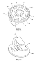
- FIG. 2A depicts a top view of a support of an imaging device, according to an embodiment of the present invention.
- Fig. 2B depicts a bottom view of a support of an imaging device, according to an embodiment of the present invention.
- top and bottom are relative terms, and may be interchangeable depending on the context.
- Figs. 7A and 7B depicts an alternate view of support 80, according to an embodiment of the present invention.
- support 80 may have mounted on it on one face an image sensor 46, one or more illumination source(s) 41, antenna 48, and possibly other components, such as optical isolation element 170 (shown in Fig. 1A and 1B).
- the embodiment shown in Fig. 7A depicts 8 illumination sources.
- Support 80 has mounted on it on another face transmitter 54, a battery support 60, for holding power source(s) 45 (which in one embodiment may be batteries), and possibly other components.
- the battery support may be any component providing battery contact so as to provide power to one or more components in device 40.
- Other sets of components may be included on the various faces or sides of a support or substrate.
- image sensor 46, one or more illumination source(s) 41, and an antenna 48 may be placed on the top side or face of the support, and transmitter 54 on the bottom side or face of the support 80.
- the various components may communicate electrically, for example, through wires or electrical contacts (not shown) on support 80 that may cross from one side of the support 80 to the other by holes or vias.
- the various components of the device 40 may be placed on the support 80 in different manners.
- the transmitter 54 and illumination source(s) 41 may be placed on the same side.
- the one or more illumination source(s) 41 may be arranged in different manners.
- the various components of the device 40 need not be mounted or configured on a support or circuit board as shown herein.
- sections of an imaging device may be optically isolated from one another.
- One or more optical isolation elements 170 may be used to optically isolate sections of the device, for example to keep light scatter from illumination source(s) 41 from reaching image sensor 46 and to separate an image sensor section 180 from one or more illumination section(s) 190.
- an illumination section includes the area including at least illumination elements and an imaging section includes areas including at least one or more image devices.
- an illumination section may include other additional components and areas, and an imaging section may include other additional components and areas.
- each of an illumination section and imaging section may be divided into two or more non-contiguous sections, and may have different configurations than shown.
- the illumination portion may include suitable illumination sources such as LEDs or white LEDs; other illumination sources may be used.
- the antenna 48 may be configured to take up a minimum of space within the device 40.
- the antenna 48 may be combined with, embedded within, substantially within, or attached to other elements, such as a support, so as to not take up a large amount of space.
- the antenna 48 may also be surrounded by or nestled within components such as a support, separation or isolation element, etc.
- antenna 48 may be placed within or mounted on a surface of the optical isolation element 170.
- antenna 48 may be coiled within or embedded within or substantially within (a portion may extend outside) isolation element 170, for example by being placed between two sections of isolation element 170 or by being molded or embedded within the isolation element 170.
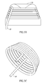
- Fig. 3A depicts optical isolation element 170 and antenna 48 according to one embodiment.
- Fig. 3B is a cutaway view depicting optical isolation element 170 and antenna 48 according to one embodiment.
- Fig. 3C depicts antenna 48 according to one embodiment. Referring to Fig. 3A, optical isolation element 170 may be in one embodiment a cone, and antenna 48 may be wrapped around the outside of optical isolation element 170.
- antenna 48 may be coiled on the inside of isolation element 170.
- Antenna 48 need not be placed within or on the isolation element 170, and the isolation element 170 need not be included.
- Optical isolation element 170 may be of other suitable shapes (e.g., Fig. 5). In alternate embodiments, other suitable numbers of optical isolation elements may be used, having different forms.
- the optical isolation elements may be, for example, extensions of components of the device, such as the illumination sources or image sensor, a piece integrated into or extending from the dome or lens, a translucent or semi-transparent member, or other suitable forms.
- antenna 48 may be mounted on the support 80.
- the antenna 48 may be mounted in a flat manner over the surface of support 80 (Fig. 2A).
- antenna 48 may be arranged around the periphery of the support 80.
- antenna 48 may be arranged in a different manner or pattern on support 80.
- antenna 48 may be embedded within or substantially within the support 80.
- the transmitter 54 may be connected to antenna 48 by, for example, wires, or connections (not shown) on the support 80 or through the support 80 (in the case, for example that the antenna 48 and transmitter 54 may be on opposite sides of the support 80).
- the antenna may not be configured to take up a small amount of space.
- the device includes a power source 45, such as one or more batteries.
- the power source 45 may include silver oxide batteries, lithium batteries, or other electrochemical cells having a high energy density, or the like. Other suitable power sources may be used. Power induction from an external source may be used.
- the location of the center of gravity (“e.g.”) vis-à-vis the geometric center of the device 40 may be of importance for the stabilization of the optical axis of the device 40 as it enters cavities larger then it's own size.
- One or more weight(s) or ballast(s) 74 may be included at one portion of the device 40, for example at the bottom of the lower portion 72 (bottom and top being relative terms, interchangeable as per the context). Weight 74 may be included at other portions of the device 40.
- a weight or ballast may take the form of other functional components of the device - for example, a battery may be positioned to alter the weight or mass balance of the device.
- Counterwight or other elements that may decrease the specific gravity may be included - for example, a gas may be included at a portion of the device to alter the specific gravity or weight distribution.
- Weight 74 may be arranged so that device 40 holds, substantially, one orientation during its traverse of the GI tract, or tends to return to such orientation when moved from that orientation.
- the center of gravity may be typically opposite to the direction of view.
- a weight may be included at one portion of device 40, to for example counter balance existing weights, and for example place the center of gravity in for example, the geometrical center of device 40.
- device 40 may be configured not to hold a specific orientation.
- the power source may be an external power source transmitting power to the device, and a controller separate from the transmitter 54 may be used.
- the image sensor 46 may be a complementary metal oxide semiconductor (CMOS) image sensor.
- CMOS image sensor may be typically an ultra low power image sensor and may be provided in chip scale packaging (CSP).
- CSP chip scale packaging
- One suitable CMOS camera may be, for example, a "camera on a chip" CMOS image sensor.
- Other types of CMOS image sensors may be used.
- other suitable image sensors may be used, such as for example, a CCD image sensor, or other suitable image sensors.
- the image sensor may be square in shape (e.g., a 256 x 256 CMOS array). Other dimensions, for example 512 x 512 elements, may be used.
- Other shapes such as for example rectangular shapes, or other suitable shapes may be used.
- In vivo image device 40 may transmit image or other information to a receiver system and the images and other information may be displayed on a display system.
- a reception and display system such as those described in embodiments in the above mentioned WO 01/65995 and/or U.S. patent 5,604,531 may be used; in alternate embodiments, other reception or display systems, having other configurations, may be used.
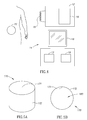
- Fig. 4 depicts elements of an imaging system according to one embodiment of the present invention.
- a receiver 12 preferably including an antenna or antenna array 15, for receiving image and possibly other data from device 40, a receiver storage unit 16, for storing image and other data, a data processor 14, a data processor storage unit 19, and an image monitor 18, for displaying, inter alia, the images transmitted by the device 40 and recorded by the receiver 12.
- the receiver 12 and receiver storage unit 16 may be small and portable, and may be worn on the patient's body during recording of the images.
- data processor 14, data processor storage unit 19 and monitor 18 may be part of a personal computer or workstation, which may include standard components such as a processor 13, a memory (e.g., storage 19, or other memory), a disk drive (not shown), and input-output devices (not shown), although alternate configurations may be possible.
- the data reception and storage components may be of another configuration. It should be emphasized that other embodiments may include a wired rather than wireless device. In such a case, certain elements shown in Fig. 1A and Fig. 4 may be omitted, such as transmitter 54, antenna 48, antenna array 15 and receiver 12.
- the device 40 may be swallowed by a patient and for example traverses the patient's GI tract, however, other body lumens or cavities may be imaged or examined, and the device need not be swallowable.
- the device 40 may transmit information (e.g., image information) in discrete portions. Each portion may for example, typically corresponds to an image or frame. Other suitable transmission methods may possible.
- the device 40 may capture image or other information once every half second, and, after capturing such an image, may for example transmit the information to the receiving antenna. Other capture rates may be possible.
- the image data recorded and transmitted may be digital color image data, although in alternate embodiments other image formats (e.g., black and white image data) may be used.
- each frame of image data may include 256 rows of 256 pixels each, each pixel including data for color and brightness, according to known methods.
- color may be represented by a mosaic of four subpixels, each sub-pixel corresponding to primaries such as red, green, or blue (where one primary may be represented twice).
- the brightness of the overall pixel may be recorded by, for example, a one byte (i.e., 0-255) brightness value.
- Other data formats may be used, and other image formats may be used.
- Fig. 5A is a side view of an optical isolation element according to one embodiment of the present invention.
- Fig. 5B is a top view of an optical isolation element according to one embodiment of the present invention.
- optical isolation element 170 may be one relatively flat ring or cone of plastic, polymer, or other suitable material.
- ABS acrylonitrile butadiene styrene
- the isolation element 170 may be of other forms, for example the cone of Fig. 3, may be made from other suitable materials (including more than one material) and may be constructed from multiple pieces.
- An antenna (Fig. 1A) may be included in or on isolation element 170.
- an antenna may be molded within the material of isolation element 170) or mounted on a surface (e.g., inner surface 171 or outer surface 172) of isolation element 170.
- isolation element 170 is shown for example as a single ring shown in cross section, but may have other suitable forms.
- the optical isolation element(s) 170 may be, for example, an opaque or translucent barrier, a light trap, an optical filter, a series of separate barriers, or any other suitable structure.
- Isolation element 170 may be mounted in the device 40 by, for example, gluing, acoustic welding, friction fit, being held by other assembled components, or by other methods. Isolation element 170 may be part of or an extension of other elements, such as a supporting surface such as for example support 80. Isolation element 170 may, for example, separate an illumination section 190 and an imaging section 180, which in Fig. 1A, for example, may be generally located within the illumination section 190. In the embodiment depicted, the imaging section 180 may be round, and the illumination section 190 may be ring shaped or substantially ring shaped.
- Embodiments of the device may be typically autonomous and typically self-contained.
- the device may be a capsule or other units where all the components are substantially contained within a container or shell, and where the device does not require any wires or cables to, for example, receive power or transmit information.
- the device may communicate with an external receiving and display system to provide display of data, control, or other functions.
- power may be provided by an internal battery or a wireless receiving system.
- Other embodiments may have other configurations and capabilities.
- components may be distributed over multiple sites or units. Control information may be received from an external source.
- the imaging device may be spherical or substantially spherical (which when used herein includes an ellipsoidal shape). Such a shape may enable the device to glide or roll over the typically moist surface of body lumens such as the stomach. Also, a spherically shaped device may glide or roll over the ridges formed on GI tract lumen walls (such as the stomach wall) rather than get stuck in or on these ridges. In such a case, the motion of the image sensor within the device may be relatively smooth and continuous. This may be in contrast to devices of other shapes (e.g., oblong shapes) that may produce jumpy motion and non-continuous images in the same context when for example tumbling over surfaces.
- other shapes e.g., oblong shapes
- An optional ballast or weight may allow one portion, such as the image sensor 46, to be usually oriented upwards.
- the images captured may tend to be not of the wall on which the device may be resting, in the case that the device may be resting on a surface in a lumen, but rather may include a view oriented outward from the wall.
- a lumen that may be relatively large e.g., the stomach or large intestine
- gravity acts on the ballast or weight in a certain manner the wall opposite the wall on which the device may be resting is imaged, rather than a wall close to the device which may block the view of the image device.
- Such an embodiment may provide a relatively steady view of a lumen, and be easily oriented to portions of such lumens that may be desired to be imaged.
- Fig. 6 depicts the device 40 in a patient's stomach 200 according to one embodiment of the present invention.
- the device 40 may tend to be oriented so that the image sensor 46 (Fig. 1A) may be oriented generally upwards.
- the image sensor 46 may capture images in, for example, directions marked as a, and does not generally capture images in directions marked as b.
- the device images one wall of a lumen from a "far wall”
- that illumination sources typically output enough light so that the far wall may be adequately illuminated.
- Various methods of altering the amount of light output by the illumination units for example, in response to detection of the amount of light required or the amount of light received by the image device, may be used.
- Embodiments of devices and methods for altering the light output from an image device are described in International Application PCT/IL02/00622 filed 26 July 2002 , assigned to the assignee of the present invention, incorporated herein by reference in its entirety.
- An antenna as described herein in various embodiments need not be used in a device having for example, a substantially spherical or a certain shape.
- antennas may be used in oblong shaped devices.
- a circuit board or series of circuit boards as described herein in various embodiments need not be used in a device having a substantially spherical or a certain shape.
- such configurations may be used in oblong shaped devices.
- an imaging device according to an embodiment of the invention having a spherical or substantially spherical shape need not include an antenna as described herein or a circuit board or internal configuration as described herein.
- a method of manufacturing a substantially spherical in vivo imaging device may include the steps of mounting an image sensor and a transmitter on a single support and encapsulating the support in a substantially spherical housing.
- an image sensor and a transmitter may be mounted on two faces of the support, typically, opposing faces.
- the support and/or housing according to embodiments of the invention may be, for example, as described above.
- device 300 may include two optical domes 302 behind which are situated illumination sources 342, two lens holder 319 and 319', two imagers 320 and 320' a transmitter such as an ASIC and a processor.
- the device 300 may further include a power source 345, which may provide power to the entirety of electrical elements of the device and an antenna 317 for transmitting video signals from the imagers 320 and 320'.
- the antenna 317 may be combined with, embedded within, substantially within, or attached to elements, such as a support e.g.
- device 300 is capable of simultaneously obtaining images of the body lumen, for example, the GI tract, from two ends of the device.
- device 300 may be a cylindrical capsule having a front end and a rear end, which is capable of passing the entire GI tract.
- the system in a cylindrical capsule can image the GI tract in the front and in the rear of the capsule.
- the various components of the device 300 may be disposed on a circuit board 350 including rigid and flexible portions; preferably the components are arranged in a stacked vertical fashion.
- rigid portion 351 of the circuit board 350 may hold a transmitter, an imager 320 and a lens holder 319 and an antenna 317, while rigid portion 361 may hold a processor, an imager 320' and a lens holder 319'; the other side of the rigid portions 351 and 361 may include, for example, a contact 341 for battery or power source 345.
- rigid portions 353 and 363 of the circuit board 350 may include, for example, an illumination source, such as one or more LEDs 342 or other illumination sources.
- each rigid portion of the circuit board may be connected to another rigid portion of the circuit board by a flexible connector portion (e.g. 322 322' and 322") of the circuit board 350.
- each rigid portion of the circuit board may include two rigid sections; sandwiched between the rigid sections is a flexible connector portion of the circuit board for connecting the rigid boards.
- other arrangements of components may be placed on a circuit board having rigid portions connected by flexible portions.
- Fig. 9 depicts a set of steps of a method for manufacture of an imaging device, according to one embodiment of the invention.
- a support for example on a circuit board e.g. a circuit board including rigid and flexible portions.
- additional components may be mounted on the support, and the configuration of the various components may vary.
- an antenna may be mounted on the support, possibly on a face or side different from the transmitter.
- other component configurations may be achieved; for example, an image sensor and transmitter need not be mounted on the same support.
- the support may be enclosed or encapsulating in a substantially spherical housing.
- Other components may be included; for example a ballast or other weight may be included within housing.
Abstract
Description
- The present invention relates generally to in vivo imaging devices, and more specifically to an in-vivo imaging device with a spherical, ellipsoidal, oval, or similar shape.
- Devices and methods for performing in-vivo imaging of passages or cavities within a body are known in the art. Such devices may include, inter alia, various endoscopic imaging systems and devices for performing imaging in various internal body cavities. Some of these devices use a wireless connection to transmit image data.
- Several factors have so far limited the extent to which the size of an imaging device can be reduced. A first factor may be the size of the circuitry connected to the imaging sensor portion of the imaging device. A second factor may be the cumulative widths of the several components of the imaging device. Another factor limiting the size reduction or space usage in imaging devices may be the size of the antenna for transmitting (and/or receiving) data such as image data.
- The size of available imaging devices relative to the small openings of many body lumens may be limiting. A reduced size imaging device may provide greater access to body lumens with narrow or restricted points of access. Further, reducing the space taken up by components of imaging devices may allow for other components to be included.
- When some in-vivo image devices image lumens that may be relatively large, it may be desirable for the image device to provide a steady image stream of one wall of the lumen. When certain image devices move over the surfaces of such lumens, they may, for example, tumble end over end, thus producing jumpy motion or non-continuous images. Certain image devices may also not provide a relatively steady view of such lumens, and may not easily orient to portions of such lumens that may be desired to be imaged.
- In one embodiment of the present invention an in-vivo imaging device may have an oval, spherical or substantially spherical shape. In another embodiment an imaging device may include a support supporting an image sensor, an illumination source, and an antenna on a first plane of the support and a transmitter and battery support on a second plane of the support. The antenna may be combined with or attached to other elements in the in vivo imaging device so as to possibly reduce the amount of space taken up by it.
- The invention is herein described, by way of example only, with reference to the accompanying drawings, in which like components are designated by like reference numerals, wherein:
- Fig. 1A shows a schematic diagram of an in vivo imaging device according to one embodiment of the present invention;
- Fig. 1B depicts a perspective view of an in vivo imaging device according to one embodiment of the present invention;
- Fig. 2A depicts a top view of a support of an imaging device, according to an embodiment of the present invention;
- Fig. 2B depicts a bottom view of a support of an imaging device, according to an embodiment of the present invention;
- Figs. 3A, 3B and 3C depict an optical isolation element and antenna according to one embodiment of the present invention;
- Fig. 4 depicts elements of an imaging system according to one embodiment of the present invention;
- Fig. 5A is a side view of an optical isolation element according to one embodiment of the present invention;
- Fig. 5B is a top view of an optical isolation element according to one embodiment of the present invention;
- Fig. 6 depicts the device in a patient's stomach according to one embodiment of the present invention;
- Fig. 7A depicts a top view of a support of an imaging device, according to an embodiment of the present invention;
- Fig. 7B depicts a bottom view of a support of an imaging device, according to an embodiment of the present invention;
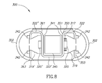
- Fig. 8 schematically illustrates an in vivo imaging device according to another embodiment of the invention; and
- Fig. 9 depicts a set of steps of a method for manufacture of an imaging device, according to one embodiment of the invention.
- It will be appreciated that for simplicity and clarity of illustration, elements shown in the figures have not necessarily been drawn to scale. For example, the dimensions of some of the elements may be exaggerated relative to other elements for clarity. Further, where considered appropriate, reference numerals may be repeated among the figures to indicate corresponding or analogous elements.
- In the following detailed description, numerous specific details are set forth in order to provide a thorough understanding of the invention. However, it will be understood by those skilled in the art that the present invention may be practiced without these specific details. In other instances, well-known methods, procedures, components and circuits have not been described in detail so as not to obscure the present invention.
- One embodiment of the device and system of the present invention may include an imaging device, which may be, for example, a capsule, for example, particularly suited for imaging the stomach or other large lumens (e.g., large intestine), although of course other suitable portions of the body may be imaged. In such applications, for example, high resolution may not be necessary, but there may for example be a need to image a wide field of view. In some embodiments, the entire organ may be imaged for example, to diagnose if a suspected pathology exists; it may be the case that the details of pathology may be less important than its existence. An imaging according to some embodiments device may be used for other suitable purposes besides diagnosing of pathology. Of course, high resolution image devices may be used with embodiments of the present invention, and embodiments of the present invention may be used in other applications. Embodiments of the present invention may allow, for example to reduced size and/or components of an in-vivo image device.
- Various embodiments of the present invention may be incorporated into or used with an imaging device similar to some embodiments described in
International Application publication number WO 01/65995 U.S. patent 5,604,531 to Iddan et al. , which is assigned to the common assignee of the present invention and which is hereby incorporated by reference in its entirety. In other embodiments, embodiments of the present invention may be incorporated into or used with other imaging capsules or devices, having other structures. - Fig. 1A shows a schematic diagram of an in vivo imaging device according to one embodiment of the present invention. Fig. 1B depicts a perspective view of an in vivo imaging device according to one embodiment of the present invention. Referring to Figs. 1A and 1B, in an exemplary embodiment, a
device 40 may be a swallowable device capturing for example images and other data from within a body lumen, typically the GI tract. Other body lumens may be examined as well by other means other than swallowing, for example insertion with a suitable tool, for example with an endoscope, catheter, implantation, etc. According to one embodiment a generallytransparent dome 52 provides a generally transparent cover for the optical elements, provides a sealed barrier to bodily fluids, and may perform other functions (such as holding optical elements). A shell orcontainer 53 may provide a container for components. In one embodiment, the shell orcontainer 53 provides the overall shape for the device; e.g., substantially spherical, etc. Alternately, other components may also provide shape. Anupper portion 70 may be separated from alower portion 72 by, for example, asupport 80; in an alternate embodiment such a separation may not be performed. When used herein, upper and lower are relative terms, to be used interchangeably as per the context. The portions may not evenly split the device. The shell or container may be uniform, or may have multiple components. For example, a portion of the shell may be a clear optical window or dome, or the shell may be manufactured from multiple components. - Typically, the outer shape of the device 40 (which in the embodiment shown is formed by
dome 52 andshell 53, but may be formed by other components) may be ellipsoidal, spherical or substantially spherical. When used herein, "spherical or substantially spherical" may be defined as a geometrical shape having a diameter r and a longitudinal axis L wherein r <= L <= 1.5r. When L=1.5r, the shape may be an ellipsoid, and also may be considered to be oval shaped. In one embodiment r may be about 11.4 mm; however, other dimensions may be used. Note that, asdevice 40 may be rotated about an axis, different cross sections of thedevice 40 may differ - e.g., thedevice 40 may be a somewhat irregular sphere or ellipsoid. The shape of thedevice 40 may differ when viewed from different angles. - Typically,
device 40 may include at least one sensor such as animage sensor 46, for capturing images (and possibly other sensors, such as a temperature sensor, a pH sensor, a pressure sensor, etc.). A set of illumination source(s) 41 (where set can include one item) such as, for example, a set of LEDs, such as for example white LEDs (other suitable elements may be used) may be used to illuminate an area for viewing. - An optical system, may include, for example, one or more optical elements, such as one or more lenses or
composite lens assemblies 50, one or more suitable optical filters (not shown), or any other suitable optical elements (not shown), may aid in focusing reflected light onto theimage sensor 46 and performing other light processing. Thelens 50 may be mounted on anoptical isolation element 170.Isolation element 170 may aid in partially or completely optically isolating sections of the device from each other, for example by preventing light from illumination sources from reaching imaging systems directly, as opposed to via reflecting off of imaged objects. Other systems or methods for positioning the lens(es) may be used. In one embodiment, the field of view may be 80-90 degrees; other suitable fields of view may be used, such as a field of view of 140 degrees, or other suitable fields of view, such as a field of view in the range of between 80 - 140 degrees. The focus distance may typically be between 0 to 40 mm; however, other suitable distances may be used. -
Device 40 may, for example, have components similar to components in embodiments described inU.S. Patent No. 5,604,531 and/orWO 01/65995 device 40 may be any sort of in-vivo sensor device and may have other components and configurations. For example,device 40 or components ofdevice 40 may be included in an endoscope. -
Device 40 typically may include atransmitter 54, for transmitting image and other (e.g., non-image) information to a receiving device, and may include other components, such as, for example, a compression module (not shown), for compressing data. Thetransmitter 54 may typically be an ultra low power radio frequency (RF) transmitter with high bandwidth input, possibly provided in chip scale packaging. Thetransmitter 54 may also include circuitry and functionality for controlling thedevice 40.Transmitter 54 may be, for example, an ASIC, "computer on a chip", microcontroller, etc., or other component.Transmitter 54 may be in one embodiment a generalized integrated device that may include, for example, transmitter and/or receiver capability, a controller, drivers for the illumination devices, and possibly a variety of analog and/or digital elements. According to some embodiments of the present invention,antenna 48 and/ortransmitter 54 may be used for receiving data, for example from an external system such as an external receiving and display system. - Components such as
image sensor 46, illumination source(s) 41,optical isolation element 170, andtransmitter 54 may be mounted on thesupport 80, which may be, for example, a circuit board e.g. a Printed Circuit Board (PCB) or plastic board or sheet. According to one embodiment of the present invention, the circuit board may include rigid and flexible portions. According to some embodiments of the present invention, each rigid portion of the circuit board may be connected to another rigid portion of the circuit board by a flexible connector portion of the circuit board. According to one embodiment of the present invention, each rigid portion of the circuit board may include two rigid sections; sandwiched between the rigid sections is a flexible connector portion of the circuit board for connecting the rigid boards. In alternate embodiments, other arrangements of components may be placed on a circuit board having rigid portions connected by flexible portions. According to some embodiments of the present invention,Support 80 may be another structure or substrate, and may be made of other substances, and components need not be mounted on a separate support. - In alternate embodiments, a circuit board having rigid portions and flexible portions may be used to arrange and hold components in other in vivo sensing devices, such as a swallowable capsule measuring pH, temperature or pressure, or in a swallowable imaging capsule having components other than those described above. Such circuit boards may be similar to embodiments described in
US application number 10/879,054 US application number 60/298,387 - In one
embodiment image sensor 46, illumination source(s) 41 andtransmitter 54 and/or other components may be mounted on thesupport 80 so as to minimize the amount of space taken up by such components. Fig. 2A depicts a top view of a support of an imaging device, according to an embodiment of the present invention. Fig. 2B depicts a bottom view of a support of an imaging device, according to an embodiment of the present invention. When used herein, top and bottom are relative terms, and may be interchangeable depending on the context. - Figs. 7A and 7B depicts an alternate view of
support 80, according to an embodiment of the present invention. Referring to Figs. 7A and 7B,support 80 may have mounted on it on one face animage sensor 46, one or more illumination source(s) 41,antenna 48, and possibly other components, such as optical isolation element 170 (shown in Fig. 1A and 1B). The embodiment shown in Fig. 7A depicts 8 illumination sources. Other suitable numbers of illumination sources may be used.Support 80 has mounted on it on anotherface transmitter 54, abattery support 60, for holding power source(s) 45 (which in one embodiment may be batteries), and possibly other components. In other embodiments, the battery support may be any component providing battery contact so as to provide power to one or more components indevice 40. Other sets of components may be included on the various faces or sides of a support or substrate. - Referring again to Fig. 1A,
image sensor 46, one or more illumination source(s) 41, and an antenna 48 (through which thetransmitter 54 may transmit) may be placed on the top side or face of the support, andtransmitter 54 on the bottom side or face of thesupport 80. The various components may communicate electrically, for example, through wires or electrical contacts (not shown) onsupport 80 that may cross from one side of thesupport 80 to the other by holes or vias. - Various components of the
device 40, and other components, may be placed on thesupport 80 in different manners. For example, thetransmitter 54 and illumination source(s) 41 may be placed on the same side. The one or more illumination source(s) 41 may be arranged in different manners. In an alternate embodiment, the various components of thedevice 40 need not be mounted or configured on a support or circuit board as shown herein. - In one embodiment of the present invention, sections of an imaging device may be optically isolated from one another. One or more
optical isolation elements 170 may be used to optically isolate sections of the device, for example to keep light scatter from illumination source(s) 41 from reachingimage sensor 46 and to separate animage sensor section 180 from one or more illumination section(s) 190. - Generally, an illumination section includes the area including at least illumination elements and an imaging section includes areas including at least one or more image devices. However, an illumination section may include other additional components and areas, and an imaging section may include other additional components and areas. Further, each of an illumination section and imaging section may be divided into two or more non-contiguous sections, and may have different configurations than shown. The illumination portion may include suitable illumination sources such as LEDs or white LEDs; other illumination sources may be used.
- In certain embodiments, the
antenna 48 may be configured to take up a minimum of space within thedevice 40. For example, theantenna 48 may be combined with, embedded within, substantially within, or attached to other elements, such as a support, so as to not take up a large amount of space. Theantenna 48 may also be surrounded by or nestled within components such as a support, separation or isolation element, etc. - In one embodiment,
antenna 48 may be placed within or mounted on a surface of theoptical isolation element 170. In the embodiment shown in Fig. 1A,antenna 48 may be coiled within or embedded within or substantially within (a portion may extend outside)isolation element 170, for example by being placed between two sections ofisolation element 170 or by being molded or embedded within theisolation element 170. Fig. 3A depictsoptical isolation element 170 andantenna 48 according to one embodiment. Fig. 3B is a cutaway view depictingoptical isolation element 170 andantenna 48 according to one embodiment. Fig. 3C depictsantenna 48 according to one embodiment. Referring to Fig. 3A,optical isolation element 170 may be in one embodiment a cone, andantenna 48 may be wrapped around the outside ofoptical isolation element 170. Referring to Fig. 3b,antenna 48 may be coiled on the inside ofisolation element 170.Antenna 48 need not be placed within or on theisolation element 170, and theisolation element 170 need not be included.Optical isolation element 170 may be of other suitable shapes (e.g., Fig. 5). In alternate embodiments, other suitable numbers of optical isolation elements may be used, having different forms. The optical isolation elements may be, for example, extensions of components of the device, such as the illumination sources or image sensor, a piece integrated into or extending from the dome or lens, a translucent or semi-transparent member, or other suitable forms. - In another embodiment,
antenna 48 may be mounted on thesupport 80. For example, theantenna 48 may be mounted in a flat manner over the surface of support 80 (Fig. 2A). In Fig. 2A,antenna 48 may be arranged around the periphery of thesupport 80. Alternately,antenna 48 may be arranged in a different manner or pattern onsupport 80. For example,antenna 48 may be embedded within or substantially within thesupport 80. - The
transmitter 54 may be connected toantenna 48 by, for example, wires, or connections (not shown) on thesupport 80 or through the support 80 (in the case, for example that theantenna 48 andtransmitter 54 may be on opposite sides of the support 80). In alternate embodiments, the antenna may not be configured to take up a small amount of space. - Referring again to Fig. 1A, typically, the device includes a
power source 45, such as one or more batteries. For example, thepower source 45 may include silver oxide batteries, lithium batteries, or other electrochemical cells having a high energy density, or the like. Other suitable power sources may be used. Power induction from an external source may be used. - In one embodiment, the location of the center of gravity ("e.g.") vis-à-vis the geometric center of the
device 40 may be of importance for the stabilization of the optical axis of thedevice 40 as it enters cavities larger then it's own size. One or more weight(s) or ballast(s) 74 may be included at one portion of thedevice 40, for example at the bottom of the lower portion 72 (bottom and top being relative terms, interchangeable as per the context).Weight 74 may be included at other portions of thedevice 40. A weight or ballast may take the form of other functional components of the device - for example, a battery may be positioned to alter the weight or mass balance of the device. Counterwight or other elements that may decrease the specific gravity may be included - for example, a gas may be included at a portion of the device to alter the specific gravity or weight distribution.Weight 74 may be arranged so thatdevice 40 holds, substantially, one orientation during its traverse of the GI tract, or tends to return to such orientation when moved from that orientation. The center of gravity may be typically opposite to the direction of view. In other embodiments, a weight may be included at one portion ofdevice 40, to for example counter balance existing weights, and for example place the center of gravity in for example, the geometrical center ofdevice 40. In one embodiment of the present invention,device 40 may be configured not to hold a specific orientation. - Other components and sets of components may be used. For example, the power source may be an external power source transmitting power to the device, and a controller separate from the
transmitter 54 may be used. - In one embodiment, the
image sensor 46 may be a complementary metal oxide semiconductor (CMOS) image sensor. The CMOS image sensor may be typically an ultra low power image sensor and may be provided in chip scale packaging (CSP). One suitable CMOS camera may be, for example, a "camera on a chip" CMOS image sensor. Other types of CMOS image sensors may be used. In another embodiment, other suitable image sensors may be used, such as for example, a CCD image sensor, or other suitable image sensors. Typically, the image sensor may be square in shape (e.g., a 256 x 256 CMOS array). Other dimensions, for example 512 x 512 elements, may be used. Other shapes, such as for example rectangular shapes, or other suitable shapes may be used. - In
vivo image device 40 may transmit image or other information to a receiver system and the images and other information may be displayed on a display system. In one embodiment, a reception and display system such as those described in embodiments in the above mentionedWO 01/65995 U.S. patent 5,604,531 may be used; in alternate embodiments, other reception or display systems, having other configurations, may be used. - Fig. 4 depicts elements of an imaging system according to one embodiment of the present invention. Referring to Fig. 4, preferably, located outside the patient's body in one or more locations, may be a
receiver 12, preferably including an antenna orantenna array 15, for receiving image and possibly other data fromdevice 40, areceiver storage unit 16, for storing image and other data, adata processor 14, a dataprocessor storage unit 19, and animage monitor 18, for displaying, inter alia, the images transmitted by thedevice 40 and recorded by thereceiver 12. Typically, thereceiver 12 andreceiver storage unit 16 may be small and portable, and may be worn on the patient's body during recording of the images. Typically,data processor 14, dataprocessor storage unit 19 and monitor 18 may be part of a personal computer or workstation, which may include standard components such as aprocessor 13, a memory (e.g.,storage 19, or other memory), a disk drive (not shown), and input-output devices (not shown), although alternate configurations may be possible. - In alternate embodiments, the data reception and storage components may be of another configuration. It should be emphasized that other embodiments may include a wired rather than wireless device. In such a case, certain elements shown in Fig. 1A and Fig. 4 may be omitted, such as
transmitter 54,antenna 48,antenna array 15 andreceiver 12. - Typically, the
device 40 may be swallowed by a patient and for example traverses the patient's GI tract, however, other body lumens or cavities may be imaged or examined, and the device need not be swallowable. Typically, thedevice 40 may transmit information (e.g., image information) in discrete portions. Each portion may for example, typically corresponds to an image or frame. Other suitable transmission methods may possible. For example, thedevice 40 may capture image or other information once every half second, and, after capturing such an image, may for example transmit the information to the receiving antenna. Other capture rates may be possible. Typically, the image data recorded and transmitted may be digital color image data, although in alternate embodiments other image formats (e.g., black and white image data) may be used. In one embodiment, each frame of image data may include 256 rows of 256 pixels each, each pixel including data for color and brightness, according to known methods. For example, in each pixel, color may be represented by a mosaic of four subpixels, each sub-pixel corresponding to primaries such as red, green, or blue (where one primary may be represented twice). The brightness of the overall pixel may be recorded by, for example, a one byte (i.e., 0-255) brightness value. Other data formats may be used, and other image formats may be used. - Fig. 5A is a side view of an optical isolation element according to one embodiment of the present invention. Fig. 5B is a top view of an optical isolation element according to one embodiment of the present invention. Referring now to Figs. 5A and 5B,
optical isolation element 170 may be one relatively flat ring or cone of plastic, polymer, or other suitable material. For example, ABS (acrylonitrile butadiene styrene) may be used. Theisolation element 170 may be of other forms, for example the cone of Fig. 3, may be made from other suitable materials (including more than one material) and may be constructed from multiple pieces. An antenna (Fig. 1A) may be included in or onisolation element 170. For example, an antenna may be molded within the material of isolation element 170) or mounted on a surface (e.g.,inner surface 171 or outer surface 172) ofisolation element 170. - In Fig.
1A isolation element 170 is shown for example as a single ring shown in cross section, but may have other suitable forms. The optical isolation element(s) 170 may be, for example, an opaque or translucent barrier, a light trap, an optical filter, a series of separate barriers, or any other suitable structure. -
Isolation element 170 may be mounted in thedevice 40 by, for example, gluing, acoustic welding, friction fit, being held by other assembled components, or by other methods.Isolation element 170 may be part of or an extension of other elements, such as a supporting surface such as forexample support 80.Isolation element 170 may, for example, separate anillumination section 190 and animaging section 180, which in Fig. 1A, for example, may be generally located within theillumination section 190. In the embodiment depicted, theimaging section 180 may be round, and theillumination section 190 may be ring shaped or substantially ring shaped. - Embodiments of the device may be typically autonomous and typically self-contained. For example, the device may be a capsule or other units where all the components are substantially contained within a container or shell, and where the device does not require any wires or cables to, for example, receive power or transmit information. The device may communicate with an external receiving and display system to provide display of data, control, or other functions. For example, power may be provided by an internal battery or a wireless receiving system. Other embodiments may have other configurations and capabilities. For example, components may be distributed over multiple sites or units. Control information may be received from an external source.
- In one embodiment, the imaging device may be spherical or substantially spherical (which when used herein includes an ellipsoidal shape). Such a shape may enable the device to glide or roll over the typically moist surface of body lumens such as the stomach. Also, a spherically shaped device may glide or roll over the ridges formed on GI tract lumen walls (such as the stomach wall) rather than get stuck in or on these ridges. In such a case, the motion of the image sensor within the device may be relatively smooth and continuous. This may be in contrast to devices of other shapes (e.g., oblong shapes) that may produce jumpy motion and non-continuous images in the same context when for example tumbling over surfaces.
- An optional ballast or weight may allow one portion, such as the
image sensor 46, to be usually oriented upwards. In such an embodiment, the images captured may tend to be not of the wall on which the device may be resting, in the case that the device may be resting on a surface in a lumen, but rather may include a view oriented outward from the wall. In a lumen that may be relatively large (e.g., the stomach or large intestine), when the patient may be oriented so gravity acts on the ballast or weight in a certain manner, the wall opposite the wall on which the device may be resting is imaged, rather than a wall close to the device which may block the view of the image device. Such an embodiment may provide a relatively steady view of a lumen, and be easily oriented to portions of such lumens that may be desired to be imaged. - Fig. 6 depicts the
device 40 in a patient'sstomach 200 according to one embodiment of the present invention. Referring to Fig. 6, if weight orballast 74 may be included indevice 40, thedevice 40 may tend to be oriented so that the image sensor 46 (Fig. 1A) may be oriented generally upwards. Thus, assuming thestomach 200 may be oriented so that the top 200' may be above the bottom 200", theimage sensor 46 may capture images in, for example, directions marked as a, and does not generally capture images in directions marked as b. - In embodiments where the device images one wall of a lumen from a "far wall", that illumination sources typically output enough light so that the far wall may be adequately illuminated. Various methods of altering the amount of light output by the illumination units, for example, in response to detection of the amount of light required or the amount of light received by the image device, may be used. Embodiments of devices and methods for altering the light output from an image device are described in International Application
PCT/IL02/00622 filed 26 July 2002 - According to some embodiments of the invention there is provided a method of manufacturing a substantially spherical in vivo imaging device. According to one embodiment the method may include the steps of mounting an image sensor and a transmitter on a single support and encapsulating the support in a substantially spherical housing. According to some embodiments an image sensor and a transmitter may be mounted on two faces of the support, typically, opposing faces. The support and/or housing according to embodiments of the invention may be, for example, as described above.
- Another embodiment of the invention is schematically illustrated in Fig. 8, in which a longitudinal cross section of
device 300 is schematically shown. According to one embodiment of the present invention,device 300 may include twooptical domes 302 behind which are situatedillumination sources 342, twolens holder 319 and 319', twoimagers 320 and 320' a transmitter such as an ASIC and a processor. Thedevice 300 may further include a power source 345, which may provide power to the entirety of electrical elements of the device and anantenna 317 for transmitting video signals from theimagers 320 and 320'. According to some embodiments of the present invention, theantenna 317 may be combined with, embedded within, substantially within, or attached to elements, such as a support e.g. thelens holder 319 so as to not take up a large amount of space. Theantenna 317 may also be surrounded by or nestled within components such as a support, separation or isolation elements, etc. According to some embodiments of the present invention,device 300 is capable of simultaneously obtaining images of the body lumen, for example, the GI tract, from two ends of the device. For example,device 300 may be a cylindrical capsule having a front end and a rear end, which is capable of passing the entire GI tract. The system in a cylindrical capsule can image the GI tract in the front and in the rear of the capsule. - According to one embodiment of the present invention, the various components of the
device 300 may be disposed on acircuit board 350 including rigid and flexible portions; preferably the components are arranged in a stacked vertical fashion. For example,rigid portion 351 of thecircuit board 350 may hold a transmitter, animager 320 and alens holder 319 and anantenna 317, whilerigid portion 361 may hold a processor, an imager 320' and a lens holder 319'; the other side of therigid portions contact 341 for battery or power source 345. According to one embodiment of the present invention,rigid portions circuit board 350 may include, for example, an illumination source, such as one ormore LEDs 342 or other illumination sources. According to some embodiments of the present invention, each rigid portion of the circuit board may be connected to another rigid portion of the circuit board by a flexible connector portion (e.g. 322 322' and 322") of thecircuit board 350. According to one embodiment of the present invention, each rigid portion of the circuit board may include two rigid sections; sandwiched between the rigid sections is a flexible connector portion of the circuit board for connecting the rigid boards. In alternate embodiments, other arrangements of components may be placed on a circuit board having rigid portions connected by flexible portions. - Fig. 9 depicts a set of steps of a method for manufacture of an imaging device, according to one embodiment of the invention. Referring to Fig. 9, in
step 100, an image sensor and a transmitter are mounted on a support, for example on a circuit board e.g. a circuit board including rigid and flexible portions. In alternate embodiments, additional components may be mounted on the support, and the configuration of the various components may vary. For example, an antenna may be mounted on the support, possibly on a face or side different from the transmitter. In further embodiments, other component configurations may be achieved; for example, an image sensor and transmitter need not be mounted on the same support. - In
step 110, the support may be enclosed or encapsulating in a substantially spherical housing. Other components may be included; for example a ballast or other weight may be included within housing. - Other steps or series of steps may be used.
- While the invention has been described with respect to a limited number of embodiments, it will be appreciated that many variations, modifications and other applications of the invention may be made which are within the scope and spirit of the invention.
Claims (11)
- An in vivo imaging device comprising:a circuit board having a rigid section and a flexible section;a transmitter;an isolation element for optically isolating sections of the device; andan antenna, wherein the antenna is embedded within the isolation element.
- The in vivo imaging device according to claim 1, wherein the antenna is a single ring or a coil.
- The in vivo imaging device according to claim 1, wherein the antenna is mounted on the periphery of the rigid section.
- The in vivo imaging device according to claim 1, wherein the isolation element is selected from a group consisting of: an opaque barrier, a translucent barrier, a light trap, a lens holder and an optical filter.
- The in vivo imaging device according to claim 1, wherein the antenna is coiled within the isolation element.
- The in vivo imaging device according to claim 1, wherein the antenna is wrapped around the isolation element.
- The in vivo imaging device according to claim 1, wherein the device is autonomous.
- A method of manufacturing an in vivo imaging device, the method comprising:embedding an antenna in a rigid section of a circuit board having a plurality of rigid sections and a plurality of flexible sections; andfolding the circuit board into an in vivo imaging device housing.
- The method according to claim 8, comprising folding the circuit board such that the rigid sections of the circuit board are stacked vertically.
- The method according to claim 8, comprising mounting the antenna on a first plane of the rigid section and mounting a transmitter on a second plane.
- The method according to claim 8, comprising mounting the antenna on a first plane of the rigid section and mounting a battery support on a second plane.
Applications Claiming Priority (1)
| Application Number | Priority Date | Filing Date | Title |
|---|---|---|---|
| US11/094,253 US7833151B2 (en) | 2002-12-26 | 2005-03-31 | In vivo imaging device with two imagers |
Publications (1)
| Publication Number | Publication Date |
|---|---|
| EP1707105A1 true EP1707105A1 (en) | 2006-10-04 |
Family
ID=36609288
Family Applications (1)
| Application Number | Title | Priority Date | Filing Date |
|---|---|---|---|
| EP06111769A Withdrawn EP1707105A1 (en) | 2005-03-31 | 2006-03-27 | In vivo imaging device and method of manufacture thereof |
Country Status (3)
| Country | Link |
|---|---|
| US (1) | US7833151B2 (en) |
| EP (1) | EP1707105A1 (en) |
| JP (1) | JP2006297080A (en) |
Cited By (6)
| Publication number | Priority date | Publication date | Assignee | Title |
|---|---|---|---|---|
| EP2116177A1 (en) * | 2008-05-07 | 2009-11-11 | Olympus Medical Systems Corporation | Capsule type medical device |
| EP2135541A1 (en) * | 2007-03-30 | 2009-12-23 | Olympus Medical Systems Corp. | Capsule type medical device and method for manufacturing the same |
| US8529441B2 (en) | 2008-02-12 | 2013-09-10 | Innurvation, Inc. | Ingestible endoscopic optical scanning device |
| US8617058B2 (en) | 2008-07-09 | 2013-12-31 | Innurvation, Inc. | Displaying image data from a scanner capsule |
| US8647259B2 (en) | 2010-03-26 | 2014-02-11 | Innurvation, Inc. | Ultrasound scanning capsule endoscope (USCE) |
| US9900109B2 (en) | 2006-09-06 | 2018-02-20 | Innurvation, Inc. | Methods and systems for acoustic data transmission |
Families Citing this family (47)
| Publication number | Priority date | Publication date | Assignee | Title |
|---|---|---|---|---|
| ATE404114T1 (en) | 2001-06-18 | 2008-08-15 | Given Imaging Ltd | SWALLOWABLE IN-VIVO CAPSULE WITH A CIRCUIT BOARD HAVING RIGID AND FLEXIBLE SECTIONS |
| US7811231B2 (en) | 2002-12-31 | 2010-10-12 | Abbott Diabetes Care Inc. | Continuous glucose monitoring system and methods of use |
| US8066639B2 (en) | 2003-06-10 | 2011-11-29 | Abbott Diabetes Care Inc. | Glucose measuring device for use in personal area network |
| WO2005089103A2 (en) | 2004-02-17 | 2005-09-29 | Therasense, Inc. | Method and system for providing data communication in continuous glucose monitoring and management system |
| US8454496B2 (en) * | 2004-03-18 | 2013-06-04 | Xiaoxun Zhu | Capsule endoscope with flexible printed circuit board |
| US7766829B2 (en) | 2005-11-04 | 2010-08-03 | Abbott Diabetes Care Inc. | Method and system for providing basal profile modification in analyte monitoring and management systems |
| US8226891B2 (en) | 2006-03-31 | 2012-07-24 | Abbott Diabetes Care Inc. | Analyte monitoring devices and methods therefor |
| US7620438B2 (en) | 2006-03-31 | 2009-11-17 | Abbott Diabetes Care Inc. | Method and system for powering an electronic device |
| JP4827667B2 (en) * | 2006-09-07 | 2011-11-30 | オリンパスメディカルシステムズ株式会社 | Capsule endoscope |
| CN101516249B (en) * | 2006-09-12 | 2011-06-15 | 奥林巴斯医疗株式会社 | Capsule endoscope system, in-vivo information acquisition device, and capsule endoscope |
| US7967745B2 (en) * | 2006-09-28 | 2011-06-28 | Given Imaging, Ltd. | In vivo imaging device and method of manufacture thereof |
| JP2008142410A (en) * | 2006-12-12 | 2008-06-26 | Olympus Corp | Device introduced inside subject |
| US8702591B2 (en) * | 2007-01-12 | 2014-04-22 | Olympus Medical Systems Corp. | Capsule medical apparatus |
| US20080161639A1 (en) * | 2006-12-28 | 2008-07-03 | Olympus Medical Systems Corporation | Capsule medical apparatus and body-cavity observation method |
| US20080199894A1 (en) | 2007-02-15 | 2008-08-21 | Abbott Diabetes Care, Inc. | Device and method for automatic data acquisition and/or detection |
| US8123686B2 (en) | 2007-03-01 | 2012-02-28 | Abbott Diabetes Care Inc. | Method and apparatus for providing rolling data in communication systems |
| CA2683721C (en) | 2007-04-14 | 2017-05-23 | Abbott Diabetes Care Inc. | Method and apparatus for providing dynamic multi-stage signal amplification in a medical device |
| US7928850B2 (en) | 2007-05-08 | 2011-04-19 | Abbott Diabetes Care Inc. | Analyte monitoring system and methods |
| US8665091B2 (en) | 2007-05-08 | 2014-03-04 | Abbott Diabetes Care Inc. | Method and device for determining elapsed sensor life |
| US8461985B2 (en) | 2007-05-08 | 2013-06-11 | Abbott Diabetes Care Inc. | Analyte monitoring system and methods |
| US8456301B2 (en) | 2007-05-08 | 2013-06-04 | Abbott Diabetes Care Inc. | Analyte monitoring system and methods |
| AU2008265541B2 (en) | 2007-06-21 | 2014-07-17 | Abbott Diabetes Care, Inc. | Health management devices and methods |
| US20100016662A1 (en) * | 2008-02-21 | 2010-01-21 | Innurvation, Inc. | Radial Scanner Imaging System |
| JP5248911B2 (en) * | 2008-05-09 | 2013-07-31 | オリンパスメディカルシステムズ株式会社 | Capsule medical device |
| TW201008542A (en) * | 2008-08-26 | 2010-03-01 | Everest Display Inc | Capsule endoscope with embedded metal contacts |
| US20100130837A1 (en) * | 2008-11-25 | 2010-05-27 | The Smart Pill Corporation | Modular ingestible capsule |
| TW201028125A (en) * | 2009-01-19 | 2010-08-01 | hui-yu Zhang | Micro image pick-up apparatus |
| US9402544B2 (en) | 2009-02-03 | 2016-08-02 | Abbott Diabetes Care Inc. | Analyte sensor and apparatus for insertion of the sensor |
| WO2010127050A1 (en) | 2009-04-28 | 2010-11-04 | Abbott Diabetes Care Inc. | Error detection in critical repeating data in a wireless sensor system |
| WO2010138856A1 (en) | 2009-05-29 | 2010-12-02 | Abbott Diabetes Care Inc. | Medical device antenna systems having external antenna configurations |
| US8516691B2 (en) | 2009-06-24 | 2013-08-27 | Given Imaging Ltd. | Method of assembly of an in vivo imaging device with a flexible circuit board |
| JP5795584B2 (en) | 2009-08-31 | 2015-10-14 | アボット ダイアベティス ケア インコーポレイテッドAbbott Diabetes Care Inc. | Medical device |
| EP2473099A4 (en) | 2009-08-31 | 2015-01-14 | Abbott Diabetes Care Inc | Analyte monitoring system and methods for managing power and noise |
| US9314195B2 (en) | 2009-08-31 | 2016-04-19 | Abbott Diabetes Care Inc. | Analyte signal processing device and methods |
| DE102010009905A1 (en) * | 2010-03-02 | 2011-09-08 | Friedrich-Alexander-Universität Erlangen-Nürnberg | Method and device for acquiring information about the three-dimensional structure of the inner surface of a body cavity |
| EP2680754B1 (en) | 2011-02-28 | 2019-04-24 | Abbott Diabetes Care, Inc. | Devices, systems, and methods associated with analyte monitoring devices and devices incorporating the same |
| JP5913870B2 (en) * | 2011-08-31 | 2016-04-27 | オリンパス株式会社 | Capsule medical device |
| US9069536B2 (en) | 2011-10-31 | 2015-06-30 | Abbott Diabetes Care Inc. | Electronic devices having integrated reset systems and methods thereof |
| US9968306B2 (en) | 2012-09-17 | 2018-05-15 | Abbott Diabetes Care Inc. | Methods and apparatuses for providing adverse condition notification with enhanced wireless communication range in analyte monitoring systems |
| US20160242632A1 (en) * | 2013-10-22 | 2016-08-25 | Ganyu Lu | System and Method for Capsule Device with Multiple Phases of Density |
| US11541015B2 (en) | 2017-05-17 | 2023-01-03 | Massachusetts Institute Of Technology | Self-righting systems, methods, and related components |
| CN110996919B (en) | 2017-05-17 | 2023-07-18 | 麻省理工学院 | Self-righting product |
| CA3100710A1 (en) | 2018-05-17 | 2019-11-21 | Massachusetts Institute Of Technology | Systems for electrical stimulation |
| CN113993560A (en) | 2019-02-01 | 2022-01-28 | 麻省理工学院 | System and method for liquid injection |
| US11806904B2 (en) | 2019-09-06 | 2023-11-07 | Ambu A/S | Tip part assembly for an endoscope |
| US11541216B2 (en) | 2019-11-21 | 2023-01-03 | Massachusetts Institute Of Technology | Methods for manufacturing tissue interfacing components |
| EP4325747A1 (en) * | 2021-07-21 | 2024-02-21 | Seiko Group Corporation | Electric wave transmission device and wireless communication system |
Citations (4)
| Publication number | Priority date | Publication date | Assignee | Title |
|---|---|---|---|---|
| WO2002102224A2 (en) * | 2001-06-18 | 2002-12-27 | Given Imaging Ltd. | In vivo sensing device with a circuit board having rigid sections and flexible sections |
| WO2004059568A1 (en) * | 2002-12-26 | 2004-07-15 | Given Imaging Ltd. | In vivo imaging device and method of manufacture thereof |
| US20050043587A1 (en) * | 2003-08-04 | 2005-02-24 | Olympus Corporation | Capsular endoscope |
| US20050049461A1 (en) * | 2003-06-24 | 2005-03-03 | Olympus Corporation | Capsule endoscope and capsule endoscope system |
Family Cites Families (147)
| Publication number | Priority date | Publication date | Assignee | Title |
|---|---|---|---|---|
| US3322374A (en) | 1964-09-30 | 1967-05-30 | Jr James F King | Magnetohydrodynamic propulsion apparatus |
| US3509270A (en) | 1968-04-08 | 1970-04-28 | Ney Co J M | Interconnection for printed circuits and method of making same |
| US3616532A (en) | 1970-02-02 | 1971-11-02 | Sperry Rand Corp | Multilayer printed circuit electrical interconnection device |
| US3971362A (en) | 1972-10-27 | 1976-07-27 | The United States Of America As Represented By The Administrator Of The National Aeronautics And Space Administration | Miniature ingestible telemeter devices to measure deep-body temperature |
| JPS51141666A (en) | 1975-06-02 | 1976-12-06 | Seiko Epson Corp | Solar cell wrist watch |
| FR2362556A1 (en) | 1976-08-19 | 1978-03-17 | Thomson Csf | Printed circuit board edge connection - uses flexible strip conductor folded around edges of parallel stacked circuit boards |
| US4239040A (en) | 1976-10-19 | 1980-12-16 | Kabushiki Kaisha Daini Seikosha | Capsule for medical use |
| US4092867A (en) | 1977-02-10 | 1978-06-06 | Terrance Matzuk | Ultrasonic scanning apparatus |
| JPS5519124A (en) | 1978-07-27 | 1980-02-09 | Olympus Optical Co | Camera system for medical treatment |
| US5993378A (en) | 1980-10-28 | 1999-11-30 | Lemelson; Jerome H. | Electro-optical instruments and methods for treating disease |
| US4803992A (en) | 1980-10-28 | 1989-02-14 | Lemelson Jerome H | Electro-optical instruments and methods for producing same |
| JPS57156736A (en) | 1981-03-23 | 1982-09-28 | Olympus Optical Co | Therapeutic capsule apparatus |
| JPH0312000Y2 (en) | 1981-04-20 | 1991-03-22 | ||
| US4431005A (en) | 1981-05-07 | 1984-02-14 | Mccormick Laboratories, Inc. | Method of and apparatus for determining very accurately the position of a device inside biological tissue |
| EP0102728B1 (en) | 1982-07-27 | 1986-10-01 | Luc Technologies Limited | Bonding and bonded products |
| DE3337455A1 (en) | 1982-10-15 | 1984-04-19 | Olympus Optical Co., Ltd., Tokio/Tokyo | ENDOSCOPIC PHOTOGRAPHER |
| US4668884A (en) | 1984-04-27 | 1987-05-26 | Sanyo Electric Co | Brushless motor |
| DE3440177A1 (en) | 1984-11-02 | 1986-05-15 | Friedrich Dipl.-Ing. 8031 Eichenau Hilliges | Television recording and replay device for endoscopy on human and animal bodies |
| US4742817A (en) | 1985-05-15 | 1988-05-10 | Olympus Optical Co., Ltd. | Endoscopic apparatus having a bendable insertion section |
| NL194811C (en) | 1986-01-16 | 2003-03-04 | Mitsubishi Electric Corp | Servo circuit. |
| US4689621A (en) | 1986-03-31 | 1987-08-25 | The United States Of America As Represented By The Administrator Of The National Aeronautics And Space Administration | Temperature responsive transmitter |
| JPH0664243B2 (en) | 1986-04-30 | 1994-08-22 | オリンパス光学工業株式会社 | Endoscope |
| JPS6349125A (en) | 1986-08-16 | 1988-03-01 | 奥津 一郎 | Guide pipe for endoscope |
| US4742183A (en) | 1986-10-24 | 1988-05-03 | Napco Security Systems, Inc. | Methods and techniques for fabricating foldable printed circuit boards |
| US4939792A (en) | 1987-11-16 | 1990-07-03 | Motorola, Inc. | Moldable/foldable radio housing |
| US4936823A (en) | 1988-05-04 | 1990-06-26 | Triangle Research And Development Corp. | Transendoscopic implant capsule |
| US4844076A (en) | 1988-08-26 | 1989-07-04 | The Johns Hopkins University | Ingestible size continuously transmitting temperature monitoring pill |
| US5025704A (en) | 1989-04-14 | 1991-06-25 | Airjack Wireless Systems Incorporated | Cordless guitar transmitter |
| US5681260A (en) | 1989-09-22 | 1997-10-28 | Olympus Optical Co., Ltd. | Guiding apparatus for guiding an insertable body within an inspected object |
| JP3164609B2 (en) | 1990-10-31 | 2001-05-08 | オリンパス光学工業株式会社 | Endoscope device |
| JP2842687B2 (en) | 1990-11-27 | 1999-01-06 | 旭光学工業株式会社 | Electronic endoscope tip |
| US5267033A (en) | 1990-11-28 | 1993-11-30 | Dai Nippon Printing Co., Ltd. | Hollow body inspection system, hollow body inspection apparatus and signal transmission apparatus |
| US5217449A (en) | 1990-12-11 | 1993-06-08 | Miyarisan Kabushiki Kaisha | Medical capsule and apparatus for activating the same |
| US5395366A (en) | 1991-05-30 | 1995-03-07 | The State University Of New York | Sampling capsule and process |
| US5279607A (en) | 1991-05-30 | 1994-01-18 | The State University Of New York | Telemetry capsule and process |
| US5330427A (en) | 1991-07-02 | 1994-07-19 | Ortho Pharmaceutical Corporation | Prefilled suppository applicator |
| US5250371A (en) | 1991-12-24 | 1993-10-05 | Motorola, Inc. | Weldless surface mounted interconnect |
| US5624380A (en) | 1992-03-12 | 1997-04-29 | Olympus Optical Co., Ltd. | Multi-degree of freedom manipulator |
| FR2688997A1 (en) | 1992-03-26 | 1993-10-01 | Lambert Alain | Autonomous telemetric capsule for exploring small bowel - contains sampler for carrying out mucous biopsies, radio transmitter and position detector |
| AT399229B (en) | 1992-04-23 | 1995-04-25 | Avl Verbrennungskraft Messtech | SENSOR ARRANGEMENT FOR DIRECT OR INDIRECT OPTICAL DETERMINATION OF PHYSICAL OR CHEMICAL PARAMETERS |
| US5643175A (en) | 1992-09-01 | 1997-07-01 | Adair; Edwin L. | Sterilizable endoscope with separable disposable tube assembly |
| US5495114A (en) | 1992-09-30 | 1996-02-27 | Adair; Edwin L. | Miniaturized electronic imaging chip |
| US5508781A (en) | 1993-03-15 | 1996-04-16 | Olympus Optical Co., Ltd. | Printed circuit board |
| JP3020376B2 (en) | 1993-03-26 | 2000-03-15 | サージミヤワキ株式会社 | Internal body identification device for animals |
| US5398689A (en) | 1993-06-16 | 1995-03-21 | Hewlett-Packard Company | Ultrasonic probe assembly and cable therefor |
| US5398670A (en) | 1993-08-31 | 1995-03-21 | Ethicon, Inc. | Lumen traversing device |
| JP3392920B2 (en) | 1993-11-26 | 2003-03-31 | ペンタックス株式会社 | Endoscope tip |
| US5415181A (en) | 1993-12-01 | 1995-05-16 | The Johns Hopkins University | AM/FM multi-channel implantable/ingestible biomedical monitoring telemetry system |
| US5426263A (en) | 1993-12-23 | 1995-06-20 | Motorola, Inc. | Electronic assembly having a double-sided leadless component |
| IL108352A (en) | 1994-01-17 | 2000-02-29 | Given Imaging Ltd | In vivo video camera system |
| DE4407785A1 (en) | 1994-03-09 | 1995-09-14 | Philips Patentverwaltung | Arrangement for determining the spatial position of a scanning element displaceable relative to a reference element |
| EP0672427A1 (en) | 1994-03-17 | 1995-09-20 | Siemens-Elema AB | System for infusion of medicine into the body of a patient |
| US5819736A (en) | 1994-03-24 | 1998-10-13 | Sightline Technologies Ltd. | Viewing method and apparatus particularly useful for viewing the interior of the large intestine |
| US5448511A (en) | 1994-06-01 | 1995-09-05 | Storage Technology Corporation | Memory stack with an integrated interconnect and mounting structure |
| US5434362A (en) | 1994-09-06 | 1995-07-18 | Motorola, Inc. | Flexible circuit board assembly and method |
| US6121922A (en) | 1994-10-12 | 2000-09-19 | Veridian Erim International, Inc. | Tracking system using miniaturized concealable communications module |
| US5472804A (en) | 1994-12-01 | 1995-12-05 | Motorola, Inc. | Battery device with integrated circuit substrate packaging |
| JPH0969983A (en) | 1995-08-30 | 1997-03-11 | Matsushita Electric Ind Co Ltd | Solid-state image pickup device |
| US5697377A (en) | 1995-11-22 | 1997-12-16 | Medtronic, Inc. | Catheter mapping system and method |
| US5833603A (en) | 1996-03-13 | 1998-11-10 | Lipomatrix, Inc. | Implantable biosensing transponder |
| FR2755335B1 (en) | 1996-10-24 | 1998-11-27 | Alsthom Cge Alcatel | ESTIMATOR OF THE BALANCE DEFECT OF A QUADRATURE MODULATOR AND MODULATION STAGE USING THE SAME |
| US6225688B1 (en) | 1997-12-11 | 2001-05-01 | Tessera, Inc. | Stacked microelectronic assembly and method therefor |
| US6149581A (en) | 1997-06-12 | 2000-11-21 | Klingenstein; Ralph James | Device and method for access to the colon and small bowel of a patient |
| US6324418B1 (en) | 1997-09-29 | 2001-11-27 | Boston Scientific Corporation | Portable tissue spectroscopy apparatus and method |
| US5984875A (en) | 1997-08-22 | 1999-11-16 | Innotek Pet Products, Inc. | Ingestible animal temperature sensor |
| US6043839A (en) | 1997-10-06 | 2000-03-28 | Adair; Edwin L. | Reduced area imaging devices |
| US5929901A (en) | 1997-10-06 | 1999-07-27 | Adair; Edwin L. | Reduced area imaging devices incorporated within surgical instruments |
| US5986693A (en) | 1997-10-06 | 1999-11-16 | Adair; Edwin L. | Reduced area imaging devices incorporated within surgical instruments |
| US6304769B1 (en) | 1997-10-16 | 2001-10-16 | The Regents Of The University Of California | Magnetically directable remote guidance systems, and methods of use thereof |
| US6240312B1 (en) | 1997-10-23 | 2001-05-29 | Robert R. Alfano | Remote-controllable, micro-scale device for use in in vivo medical diagnosis and/or treatment |
| IL122578A (en) | 1997-12-12 | 2000-08-13 | Super Dimension Ltd | Wireless six-degree-of-freedom locator |
| IL122602A0 (en) | 1997-12-15 | 1998-08-16 | Tally Eitan Zeev Pearl And Co | Energy management of a video capsule |
| AU770909B2 (en) * | 1998-08-26 | 2004-03-04 | Sensors For Medicine And Science, Inc. | Optical-based sensing devices |
| JP2000210252A (en) | 1999-01-25 | 2000-08-02 | Sony Corp | Solid imaging device |
| US8636648B2 (en) | 1999-03-01 | 2014-01-28 | West View Research, Llc | Endoscopic smart probe |
| US6233476B1 (en) | 1999-05-18 | 2001-05-15 | Mediguide Ltd. | Medical positioning system |
| JP3793368B2 (en) | 1999-06-07 | 2006-07-05 | ペンタックス株式会社 | Swallowing endoscope device |
| JP3490933B2 (en) | 1999-06-07 | 2004-01-26 | ペンタックス株式会社 | Swallowable endoscope device |
| JP3462795B2 (en) | 1999-06-07 | 2003-11-05 | ペンタックス株式会社 | Swallowable endoscope device |
| JP3490932B2 (en) | 1999-06-07 | 2004-01-26 | ペンタックス株式会社 | Swallowable endoscope device |
| US7996067B2 (en) | 1999-06-15 | 2011-08-09 | Given Imaging Ltd. | In-vivo imaging device, optical system and method |
| JP2001091860A (en) | 1999-09-22 | 2001-04-06 | Asahi Optical Co Ltd | Capsule endoscope |
| JP2001095756A (en) | 1999-09-30 | 2001-04-10 | Asahi Optical Co Ltd | Capsule type endoscope |
| JP2001095755A (en) | 1999-09-30 | 2001-04-10 | Asahi Optical Co Ltd | Capsule type endoscope |
| JP2001104244A (en) | 1999-10-04 | 2001-04-17 | Asahi Optical Co Ltd | Capsule endoscope |
| JP2001104287A (en) | 1999-10-04 | 2001-04-17 | Asahi Optical Co Ltd | Capsule endoscope |
| JP2001104243A (en) | 1999-10-04 | 2001-04-17 | Asahi Optical Co Ltd | Capsule endoscope |
| JP2001104242A (en) | 1999-10-04 | 2001-04-17 | Asahi Optical Co Ltd | Capsule endoscope |
| JP2001104241A (en) | 1999-10-04 | 2001-04-17 | Asahi Optical Co Ltd | Capsule endoscope |
| JP2001112740A (en) | 1999-10-20 | 2001-04-24 | Asahi Optical Co Ltd | Capsulated endoscope |
| JP2001112709A (en) | 1999-10-20 | 2001-04-24 | Asahi Optical Co Ltd | Capsulated endscope |
| JP2001112710A (en) | 1999-10-20 | 2001-04-24 | Asahi Optical Co Ltd | Capsulated endoscope |
| JP4472069B2 (en) | 1999-11-10 | 2010-06-02 | オリンパス株式会社 | Medical capsule endoscope |
| GB9930000D0 (en) * | 1999-12-21 | 2000-02-09 | Phaeton Research Ltd | An ingestible device |
| IL134017A (en) | 2000-01-13 | 2008-04-13 | Capsule View Inc | Camera for viewing inside intestines |
| AU2001227020A1 (en) | 2000-01-19 | 2001-07-31 | Given Imaging Ltd. | A system for detecting substances |
| US7039453B2 (en) | 2000-02-08 | 2006-05-02 | Tarun Mullick | Miniature ingestible capsule |
| JP4360730B2 (en) | 2000-02-21 | 2009-11-11 | Hoya株式会社 | Capsule endoscope |
| JP2001245844A (en) | 2000-03-03 | 2001-09-11 | Asahi Optical Co Ltd | Capsule endoscope |
| KR100800040B1 (en) | 2000-03-08 | 2008-01-31 | 기븐 이미징 리미티드 | A capsule for in vivo imaging |
| US6338347B1 (en) | 2000-04-04 | 2002-01-15 | Yun-Yin Chung | Blood circulation stimulator |
| US6692430B2 (en) | 2000-04-10 | 2004-02-17 | C2Cure Inc. | Intra vascular imaging apparatus |
| US6709387B1 (en) | 2000-05-15 | 2004-03-23 | Given Imaging Ltd. | System and method for controlling in vivo camera capture and display rate |
| JP2002000556A (en) | 2000-06-26 | 2002-01-08 | Nonomura Tomosuke | Endoscope |
| US6632175B1 (en) | 2000-11-08 | 2003-10-14 | Hewlett-Packard Development Company, L.P. | Swallowable data recorder capsule medical device |
| DE10061107A1 (en) | 2000-12-07 | 2002-06-27 | Marc Henzler | Manufacturing optimization of an integrated lighting unit of an endoscope |
| IL156961A0 (en) * | 2001-01-16 | 2004-02-08 | Given Imaging Ltd | System and method for wide field imaging of body lumens |
| IL157892A0 (en) | 2001-03-14 | 2004-03-28 | Given Imaging Ltd | Method and system for detecting colorimetric abnormalities |
| US7616238B2 (en) | 2001-03-29 | 2009-11-10 | Given Imaging Ltd. | Method for timing control of an image sensor |
| WO2002080753A2 (en) | 2001-04-04 | 2002-10-17 | Given Imaging Ltd. | Induction powered in vivo imaging device |
| IL143260A (en) | 2001-05-20 | 2006-09-05 | Given Imaging Ltd | Array system and method for locating an in vivo signal source |
| IL143259A (en) | 2001-05-20 | 2006-08-01 | Given Imaging Ltd | Method for moving an object through the colon |
| US6939292B2 (en) | 2001-06-20 | 2005-09-06 | Olympus Corporation | Capsule type endoscope |
| US7161164B2 (en) | 2001-07-05 | 2007-01-09 | Given Imaging Ltd. | Device and method for attenuating radiation from in vivo electrical devices |
| US20030117491A1 (en) | 2001-07-26 | 2003-06-26 | Dov Avni | Apparatus and method for controlling illumination in an in-vivo imaging device |
| US20030043263A1 (en) | 2001-07-26 | 2003-03-06 | Arkady Glukhovsky | Diagnostic device using data compression |
| US6951536B2 (en) * | 2001-07-30 | 2005-10-04 | Olympus Corporation | Capsule-type medical device and medical system |
| IL151049A0 (en) | 2001-08-02 | 2003-04-10 | Given Imaging Ltd | In vivo imaging methods and devices |
| AU2002334354A1 (en) | 2001-09-05 | 2003-03-18 | Given Imaging Ltd. | System and method for three dimensional display of body lumens |
| US7907986B2 (en) | 2001-09-24 | 2011-03-15 | Given Imaging Ltd. | System and method for controlling a device in vivo |
| JP4643089B2 (en) | 2001-09-27 | 2011-03-02 | オリンパス株式会社 | Capsule medical device |
| JP3974769B2 (en) | 2001-11-06 | 2007-09-12 | オリンパス株式会社 | Capsule medical device |
| JP2003188489A (en) | 2001-12-14 | 2003-07-04 | Pentax Corp | Substrate structure for electronic scope |
| IL154391A (en) | 2002-02-11 | 2009-05-04 | Given Imaging Ltd | Self propelled device |
| IL154392A (en) | 2002-02-11 | 2010-06-30 | Given Imaging Ltd | Self propelled device having a magnetohydrodynamic propulsion |
| US20030195415A1 (en) | 2002-02-14 | 2003-10-16 | Iddan Gavriel J. | Device, system and method for accoustic in-vivo measuring |
| JP4363843B2 (en) | 2002-03-08 | 2009-11-11 | オリンパス株式会社 | Capsule endoscope |
| US20030216622A1 (en) | 2002-04-25 | 2003-11-20 | Gavriel Meron | Device and method for orienting a device in vivo |
| US20040254455A1 (en) | 2002-05-15 | 2004-12-16 | Iddan Gavriel J. | Magneic switch for use in a system that includes an in-vivo device, and method of use thereof |
| US7473218B2 (en) | 2002-08-06 | 2009-01-06 | Olympus Corporation | Assembling method of capsule medical apparatus |
| WO2004028336A2 (en) * | 2002-09-30 | 2004-04-08 | Given Imaging Ltd. | Reduced size imaging device |
| IL158682A (en) | 2002-10-30 | 2011-07-31 | Given Imaging Ltd | Device and method for blocking activation of an in-vivo sensor |
| US20040106849A1 (en) | 2002-12-03 | 2004-06-03 | Cho Jin-Ho | Multi-functional, bi-directional communication telemetry capsule |
| JP2004275542A (en) | 2003-03-17 | 2004-10-07 | Olympus Corp | Capsule type endoscope |
| CN100446717C (en) | 2003-04-25 | 2008-12-31 | 奥林巴斯株式会社 | Capsule endoscope and capsule endoscope system |
| CA2523306C (en) | 2003-04-25 | 2009-09-08 | Olympus Corporation | Capsule endoscope and capsule endoscope system |
| JP4328125B2 (en) | 2003-04-25 | 2009-09-09 | オリンパス株式会社 | Capsule endoscope apparatus and capsule endoscope system |
| DE10323216B3 (en) * | 2003-05-22 | 2004-12-23 | Siemens Ag | Endoscope apparatus has cameras which are provided at respective ends of endoscope capsule, such that one of camera is tilted or rotated to change photography range |
| IL162740A (en) | 2003-06-26 | 2010-06-16 | Given Imaging Ltd | Device, method and system for reduced transmission imaging |
| US7044908B1 (en) | 2003-07-08 | 2006-05-16 | National Semiconductor Corporation | Method and system for dynamically adjusting field of view in a capsule endoscope |
| US7153259B2 (en) | 2003-09-01 | 2006-12-26 | Olympus Corporation | Capsule type endoscope |
| JP2005192820A (en) * | 2004-01-07 | 2005-07-21 | Olympus Corp | Capsule type medical device |
| JP2005205071A (en) | 2004-01-26 | 2005-08-04 | Olympus Corp | Capsule type medical device |
| JP4144533B2 (en) | 2004-02-24 | 2008-09-03 | ソニー株式会社 | Playback apparatus and method |
| US7265655B2 (en) | 2004-06-02 | 2007-09-04 | Research In Motion Ltd. | Handheld computing device with power-saving notification |
| US20060015013A1 (en) | 2004-06-30 | 2006-01-19 | Zvika Gilad | Device and method for in vivo illumination |
| JP4589088B2 (en) | 2004-11-24 | 2010-12-01 | オリンパス株式会社 | In-subject information acquisition device |
-
2005
- 2005-03-31 US US11/094,253 patent/US7833151B2/en active Active
-
2006
- 2006-03-27 EP EP06111769A patent/EP1707105A1/en not_active Withdrawn
- 2006-03-30 JP JP2006094792A patent/JP2006297080A/en active Pending
Patent Citations (5)
| Publication number | Priority date | Publication date | Assignee | Title |
|---|---|---|---|---|
| WO2002102224A2 (en) * | 2001-06-18 | 2002-12-27 | Given Imaging Ltd. | In vivo sensing device with a circuit board having rigid sections and flexible sections |
| US20040171914A1 (en) * | 2001-06-18 | 2004-09-02 | Dov Avni | In vivo sensing device with a circuit board having rigid sections and flexible sections |
| WO2004059568A1 (en) * | 2002-12-26 | 2004-07-15 | Given Imaging Ltd. | In vivo imaging device and method of manufacture thereof |
| US20050049461A1 (en) * | 2003-06-24 | 2005-03-03 | Olympus Corporation | Capsule endoscope and capsule endoscope system |
| US20050043587A1 (en) * | 2003-08-04 | 2005-02-24 | Olympus Corporation | Capsular endoscope |
Cited By (13)
| Publication number | Priority date | Publication date | Assignee | Title |
|---|---|---|---|---|
| US9900109B2 (en) | 2006-09-06 | 2018-02-20 | Innurvation, Inc. | Methods and systems for acoustic data transmission |
| US10320491B2 (en) | 2006-09-06 | 2019-06-11 | Innurvation Inc. | Methods and systems for acoustic data transmission |
| EP2135541A1 (en) * | 2007-03-30 | 2009-12-23 | Olympus Medical Systems Corp. | Capsule type medical device and method for manufacturing the same |
| EP2135541A4 (en) * | 2007-03-30 | 2010-03-24 | Olympus Medical Systems Corp | Capsule type medical device and method for manufacturing the same |
| US8529441B2 (en) | 2008-02-12 | 2013-09-10 | Innurvation, Inc. | Ingestible endoscopic optical scanning device |
| US9974430B2 (en) | 2008-02-12 | 2018-05-22 | Innurvation, Inc. | Ingestible endoscopic optical scanning device |
| US9211055B2 (en) | 2008-05-07 | 2015-12-15 | Olympus Corporation | Capsule type medical device |
| EP2116177A1 (en) * | 2008-05-07 | 2009-11-11 | Olympus Medical Systems Corporation | Capsule type medical device |
| US9351632B2 (en) | 2008-07-09 | 2016-05-31 | Innurvation, Inc. | Displaying image data from a scanner capsule |
| US9788708B2 (en) | 2008-07-09 | 2017-10-17 | Innurvation, Inc. | Displaying image data from a scanner capsule |
| US8617058B2 (en) | 2008-07-09 | 2013-12-31 | Innurvation, Inc. | Displaying image data from a scanner capsule |
| US9480459B2 (en) | 2010-03-26 | 2016-11-01 | Innurvation, Inc. | Ultrasound scanning capsule endoscope |
| US8647259B2 (en) | 2010-03-26 | 2014-02-11 | Innurvation, Inc. | Ultrasound scanning capsule endoscope (USCE) |
Also Published As
| Publication number | Publication date |
|---|---|
| US20050171398A1 (en) | 2005-08-04 |
| JP2006297080A (en) | 2006-11-02 |
| US7833151B2 (en) | 2010-11-16 |
Similar Documents
| Publication | Publication Date | Title |
|---|---|---|
| US7833151B2 (en) | In vivo imaging device with two imagers | |
| US7637865B2 (en) | In vivo imaging device | |
| US7553276B2 (en) | Method and device for imaging body lumens | |
| US8063933B2 (en) | Battery contacts for an in-vivo imaging device | |
| US7625338B2 (en) | In-vivo sensing device with alterable fields of view | |
| JP5203958B2 (en) | In vivo imaging device | |
| KR101089395B1 (en) | Encapsulated endoscope | |
| CN100459926C (en) | Introducing device into subject and introducing system into subject | |
| EP1715697A2 (en) | Color filter array with blue elements | |
| WO2007074430A1 (en) | Device, system and method for activation of an in vivo device | |
| EP2244626B1 (en) | Radial scanner imaging system | |
| JP2008142410A (en) | Device introduced inside subject | |
| JP2003260023A (en) | Capsule endoscope | |
| US20050137468A1 (en) | Device, system, and method for in-vivo sensing of a substance | |
| US20120316392A1 (en) | Spherical capsule video endoscopy | |
| US20090281389A1 (en) | Device, system, and method for adaptive imaging | |
| JP5248911B2 (en) | Capsule medical device | |
| IL174552A (en) | In vivo imaging device and method of manufacture thereof | |
| WO2006003649A2 (en) | Device and method for in-vivo illumination | |
| IL161202A (en) | Method and device for imaging body lumens | |
| IL180262A (en) | Device and method for in-vivo illumination |
Legal Events
| Date | Code | Title | Description |
|---|---|---|---|
| PUAI | Public reference made under article 153(3) epc to a published international application that has entered the european phase |
Free format text: ORIGINAL CODE: 0009012 |
|
| AK | Designated contracting states |
Kind code of ref document: A1 Designated state(s): AT BE BG CH CY CZ DE DK EE ES FI FR GB GR HU IE IS IT LI LT LU LV MC NL PL PT RO SE SI SK TR |
|
| AX | Request for extension of the european patent |
Extension state: AL BA HR MK YU |
|
| 17P | Request for examination filed |
Effective date: 20070322 |
|
| RAP1 | Party data changed (applicant data changed or rights of an application transferred) |
Owner name: GIVEN IMAGING LTD. |
|
| 17Q | First examination report despatched |
Effective date: 20070427 |
|
| AKX | Designation fees paid |
Designated state(s): AT BE BG CH CY CZ DE DK EE ES FI FR GB GR HU IE IS IT LI LT LU LV MC NL PL PT RO SE SI SK TR |
|
| STAA | Information on the status of an ep patent application or granted ep patent |
Free format text: STATUS: THE APPLICATION IS DEEMED TO BE WITHDRAWN |
|
| 18D | Application deemed to be withdrawn |
Effective date: 20070908 |