EP1703271A1 - Calibration device and dye kit and utilisation thereof for characterising luminescence measuring systems - Google Patents
Calibration device and dye kit and utilisation thereof for characterising luminescence measuring systems Download PDFInfo
- Publication number
- EP1703271A1 EP1703271A1 EP06111148A EP06111148A EP1703271A1 EP 1703271 A1 EP1703271 A1 EP 1703271A1 EP 06111148 A EP06111148 A EP 06111148A EP 06111148 A EP06111148 A EP 06111148A EP 1703271 A1 EP1703271 A1 EP 1703271A1
- Authority
- EP
- European Patent Office
- Prior art keywords
- fluorescence
- calibration device
- emission
- excitation
- standards
- Prior art date
- Legal status (The legal status is an assumption and is not a legal conclusion. Google has not performed a legal analysis and makes no representation as to the accuracy of the status listed.)
- Granted
Links
- 0 CC*c1c(*(*C)[Cn]CC=CC)c(O*)c(*=*)c(C(*)=C2*)c1OC2=O Chemical compound CC*c1c(*(*C)[Cn]CC=CC)c(O*)c(*=*)c(C(*)=C2*)c1OC2=O 0.000 description 1
Images

Classifications
-
- G—PHYSICS
- G01—MEASURING; TESTING
- G01N—INVESTIGATING OR ANALYSING MATERIALS BY DETERMINING THEIR CHEMICAL OR PHYSICAL PROPERTIES
- G01N21/00—Investigating or analysing materials by the use of optical means, i.e. using sub-millimetre waves, infrared, visible or ultraviolet light
- G01N21/62—Systems in which the material investigated is excited whereby it emits light or causes a change in wavelength of the incident light
- G01N21/63—Systems in which the material investigated is excited whereby it emits light or causes a change in wavelength of the incident light optically excited
- G01N21/64—Fluorescence; Phosphorescence
- G01N21/645—Specially adapted constructive features of fluorimeters
- G01N21/6456—Spatial resolved fluorescence measurements; Imaging
- G01N21/6458—Fluorescence microscopy
-
- B—PERFORMING OPERATIONS; TRANSPORTING
- B01—PHYSICAL OR CHEMICAL PROCESSES OR APPARATUS IN GENERAL
- B01L—CHEMICAL OR PHYSICAL LABORATORY APPARATUS FOR GENERAL USE
- B01L3/00—Containers or dishes for laboratory use, e.g. laboratory glassware; Droppers
- B01L3/50—Containers for the purpose of retaining a material to be analysed, e.g. test tubes
- B01L3/502—Containers for the purpose of retaining a material to be analysed, e.g. test tubes with fluid transport, e.g. in multi-compartment structures
- B01L3/5027—Containers for the purpose of retaining a material to be analysed, e.g. test tubes with fluid transport, e.g. in multi-compartment structures by integrated microfluidic structures, i.e. dimensions of channels and chambers are such that surface tension forces are important, e.g. lab-on-a-chip
-
- C—CHEMISTRY; METALLURGY
- C09—DYES; PAINTS; POLISHES; NATURAL RESINS; ADHESIVES; COMPOSITIONS NOT OTHERWISE PROVIDED FOR; APPLICATIONS OF MATERIALS NOT OTHERWISE PROVIDED FOR
- C09K—MATERIALS FOR MISCELLANEOUS APPLICATIONS, NOT PROVIDED FOR ELSEWHERE
- C09K11/00—Luminescent, e.g. electroluminescent, chemiluminescent materials
- C09K11/06—Luminescent, e.g. electroluminescent, chemiluminescent materials containing organic luminescent materials
-
- G—PHYSICS
- G01—MEASURING; TESTING
- G01N—INVESTIGATING OR ANALYSING MATERIALS BY DETERMINING THEIR CHEMICAL OR PHYSICAL PROPERTIES
- G01N21/00—Investigating or analysing materials by the use of optical means, i.e. using sub-millimetre waves, infrared, visible or ultraviolet light
- G01N21/17—Systems in which incident light is modified in accordance with the properties of the material investigated
- G01N21/25—Colour; Spectral properties, i.e. comparison of effect of material on the light at two or more different wavelengths or wavelength bands
- G01N21/27—Colour; Spectral properties, i.e. comparison of effect of material on the light at two or more different wavelengths or wavelength bands using photo-electric detection ; circuits for computing concentration
- G01N21/274—Calibration, base line adjustment, drift correction
- G01N21/278—Constitution of standards
-
- B—PERFORMING OPERATIONS; TRANSPORTING
- B01—PHYSICAL OR CHEMICAL PROCESSES OR APPARATUS IN GENERAL
- B01L—CHEMICAL OR PHYSICAL LABORATORY APPARATUS FOR GENERAL USE
- B01L2200/00—Solutions for specific problems relating to chemical or physical laboratory apparatus
- B01L2200/14—Process control and prevention of errors
- B01L2200/148—Specific details about calibrations
-
- B—PERFORMING OPERATIONS; TRANSPORTING
- B01—PHYSICAL OR CHEMICAL PROCESSES OR APPARATUS IN GENERAL
- B01L—CHEMICAL OR PHYSICAL LABORATORY APPARATUS FOR GENERAL USE
- B01L2300/00—Additional constructional details
- B01L2300/06—Auxiliary integrated devices, integrated components
- B01L2300/0627—Sensor or part of a sensor is integrated
- B01L2300/0654—Lenses; Optical fibres
-
- B—PERFORMING OPERATIONS; TRANSPORTING
- B01—PHYSICAL OR CHEMICAL PROCESSES OR APPARATUS IN GENERAL
- B01L—CHEMICAL OR PHYSICAL LABORATORY APPARATUS FOR GENERAL USE
- B01L2300/00—Additional constructional details
- B01L2300/08—Geometry, shape and general structure
- B01L2300/0809—Geometry, shape and general structure rectangular shaped
- B01L2300/0816—Cards, e.g. flat sample carriers usually with flow in two horizontal directions
-
- B—PERFORMING OPERATIONS; TRANSPORTING
- B01—PHYSICAL OR CHEMICAL PROCESSES OR APPARATUS IN GENERAL
- B01L—CHEMICAL OR PHYSICAL LABORATORY APPARATUS FOR GENERAL USE
- B01L3/00—Containers or dishes for laboratory use, e.g. laboratory glassware; Droppers
- B01L3/50—Containers for the purpose of retaining a material to be analysed, e.g. test tubes
- B01L3/502—Containers for the purpose of retaining a material to be analysed, e.g. test tubes with fluid transport, e.g. in multi-compartment structures
- B01L3/5025—Containers for the purpose of retaining a material to be analysed, e.g. test tubes with fluid transport, e.g. in multi-compartment structures for parallel transport of multiple samples
-
- C—CHEMISTRY; METALLURGY
- C09—DYES; PAINTS; POLISHES; NATURAL RESINS; ADHESIVES; COMPOSITIONS NOT OTHERWISE PROVIDED FOR; APPLICATIONS OF MATERIALS NOT OTHERWISE PROVIDED FOR
- C09K—MATERIALS FOR MISCELLANEOUS APPLICATIONS, NOT PROVIDED FOR ELSEWHERE
- C09K2211/00—Chemical nature of organic luminescent or tenebrescent compounds
- C09K2211/10—Non-macromolecular compounds
- C09K2211/1003—Carbocyclic compounds
- C09K2211/1007—Non-condensed systems
-
- C—CHEMISTRY; METALLURGY
- C09—DYES; PAINTS; POLISHES; NATURAL RESINS; ADHESIVES; COMPOSITIONS NOT OTHERWISE PROVIDED FOR; APPLICATIONS OF MATERIALS NOT OTHERWISE PROVIDED FOR
- C09K—MATERIALS FOR MISCELLANEOUS APPLICATIONS, NOT PROVIDED FOR ELSEWHERE
- C09K2211/00—Chemical nature of organic luminescent or tenebrescent compounds
- C09K2211/10—Non-macromolecular compounds
- C09K2211/1003—Carbocyclic compounds
- C09K2211/1011—Condensed systems
-
- C—CHEMISTRY; METALLURGY
- C09—DYES; PAINTS; POLISHES; NATURAL RESINS; ADHESIVES; COMPOSITIONS NOT OTHERWISE PROVIDED FOR; APPLICATIONS OF MATERIALS NOT OTHERWISE PROVIDED FOR
- C09K—MATERIALS FOR MISCELLANEOUS APPLICATIONS, NOT PROVIDED FOR ELSEWHERE
- C09K2211/00—Chemical nature of organic luminescent or tenebrescent compounds
- C09K2211/10—Non-macromolecular compounds
- C09K2211/1018—Heterocyclic compounds
- C09K2211/1025—Heterocyclic compounds characterised by ligands
- C09K2211/1029—Heterocyclic compounds characterised by ligands containing one nitrogen atom as the heteroatom
- C09K2211/1033—Heterocyclic compounds characterised by ligands containing one nitrogen atom as the heteroatom with oxygen
-
- C—CHEMISTRY; METALLURGY
- C09—DYES; PAINTS; POLISHES; NATURAL RESINS; ADHESIVES; COMPOSITIONS NOT OTHERWISE PROVIDED FOR; APPLICATIONS OF MATERIALS NOT OTHERWISE PROVIDED FOR
- C09K—MATERIALS FOR MISCELLANEOUS APPLICATIONS, NOT PROVIDED FOR ELSEWHERE
- C09K2211/00—Chemical nature of organic luminescent or tenebrescent compounds
- C09K2211/10—Non-macromolecular compounds
- C09K2211/1018—Heterocyclic compounds
- C09K2211/1025—Heterocyclic compounds characterised by ligands
- C09K2211/1088—Heterocyclic compounds characterised by ligands containing oxygen as the only heteroatom
-
- Y—GENERAL TAGGING OF NEW TECHNOLOGICAL DEVELOPMENTS; GENERAL TAGGING OF CROSS-SECTIONAL TECHNOLOGIES SPANNING OVER SEVERAL SECTIONS OF THE IPC; TECHNICAL SUBJECTS COVERED BY FORMER USPC CROSS-REFERENCE ART COLLECTIONS [XRACs] AND DIGESTS
- Y10—TECHNICAL SUBJECTS COVERED BY FORMER USPC
- Y10T—TECHNICAL SUBJECTS COVERED BY FORMER US CLASSIFICATION
- Y10T436/00—Chemistry: analytical and immunological testing
- Y10T436/10—Composition for standardization, calibration, simulation, stabilization, preparation or preservation; processes of use in preparation for chemical testing
- Y10T436/109163—Inorganic standards or controls
Definitions
- the invention relates to a calibrating device for characterizing luminescence measuring systems, in particular spectrally resolving, widefield and / or confocal imaging systems, a kit comprising the calibrating device and a dye set as well as uses of the device or the kit.
- Each luminescence measurement technology provides measurement data that is composed of analyzer-specific and device-specific contributions.
- the unwanted device-specific contributions reflect the wavelength and polarization dependence of device components of the measuring device used. Responsible for these dependencies are in particular the optical components contained in the excitation and emission channel of the device, the excitation light source and the detection systems used.
- Photoluminescence meters consist of an excitation channel, which i.a. contains an excitation light source and a wavelength-selecting optical component and a generally perpendicular to the beam path of the excitation light arranged emission channel with which the light emitted by the located in the sample chamber fluorophore light absorption (photoluminescence) is recorded.
- a defined part of the excitation light is coupled into a reference channel via a beam splitter, which contains an optical component such as a mirror or a scatterer and a (reference) detector.
- the current excitation light intensity is recorded at the excitation wavelength, so as to detect short-term fluctuations of the excitation light intensity.
- the detection of the abovementioned device-specific contributions to the fluorescence signal can be effected by the determination of so-called correction functions which describe the wavelength and polarization dependencies of these effects for the emission and excitation channels of the respective device. These correction functions are determined separately.
- the emission correction function contains the wavelength- and polarization-dependent transmission efficiency of the optical components in the emission channel and the wavelength- and polarization-dependent spectral sensitivity of the detection system used.
- the excitation correction function describes the wavelength-dependent spectral radiance of the excitation light source and the wavelength- and polarization-dependent transmission efficiency of the optical components in the excitation channel.
- certified physical transfer standards for recording the device-specific effects.
- Certified receiver standards are typically used to calibrate the excitation channel, and standard lamps certified to calibrate the emission channel.
- Disadvantageous for the use of physical transfer standards are the users' good optics knowledge required for the application, their difficult installation, costly recalibrations, changes in the spectral radiance of standard lamps depending on the duration of combustion, and, in the case of standard lamp emission correction, the different emission characteristics of the lamp and the sample more than three orders of magnitude different spectral radiance of Transfernormormal and a typical luminescent sample. All this can lead to faulty and unsatisfactory correction functions and is also complex and costly.
- quantum counters are used for the excitation correction. These are highly concentrated dye solutions that completely absorb incident light quanta and emit wavelength-independent fluorescence quantum efficiencies. Quantum meters provide very concentration- and geometry-dependent measurement data and are also prone to polarization effects. Standardized calibration procedures with defined concentrations in combination with defined measurement geometries are not available for quantum counters.
- fluorescence standards which are typically based on the photoluminescence of a chemical compound.
- Spectral fluorescence standards or so-called emission and excitation standards with known (for device-specific effects) corrected emission or excitation spectra can be used to determine the spectral characteristics of photoluminescence measurement systems as part of a device calibration.
- fluorescence standards are used in various forms, in particular in the form of solutions or embedded in solid polymer or glass matrices.
- the advantage of fluorescence standards, in particular in the form of solutions is that they are very similar to the luminescent samples to be investigated in terms of their luminescence intensity and emission characteristics. Fluorescence standards thus allow the (spectral) calibration under the conditions used in typical sample measurements.
- Fluorescence standards can be measured in many different device types, formats and measurement geometries and are thus also suitable for the calibration of fluorescence measurement systems with special sample geometries or formats, for example with microcuvettes, microtiter plates or cryostat systems. Only fluorescence standards allow the calibration to be carried out in the same cuvette and measuring arrangement as the actual sample measurement and thus provide optimum calibration results.
- the problem with fluorescence standards is the large number of substance and luminescence properties to be defined.
- the prerequisite for the suitability of a transfer standard is the complete characterization of all application - relevant properties including the method used and the specification of the transfer standard Measurement uncertainty and a sufficient long-term stability in the solid pure state and in solution or embedded in a matrix.
- the spectral range in which a fluorescence standard can be used for calibration is limited by the position and width of the fluorescence band, and in the case of excitation standards only the longest wavelength band should possibly be used.
- the emission standard quinine sulphate covers z. B. only the spectral range of about 400 to 550 nm.
- standard combinations so far.
- a combination of emission standards consisting of fluorophore-containing polymer films with NIST-certified emission spectra is known (US Pat.
- fluorophore-containing polymethylmethacrylate (PMMA) blocks in cuvette form are known as emission and excitation standards.
- the fluorophores used have i. A. strongly structured emission and excitation spectra and steeply rising flanks, resulting in a no longer negligible dependence of the fluorescence profiles of the monochromator bandpass and an increase in the calibration uncertainty.
- uncertainties in the waveness lead to large errors in fluorescence intensity.
- the spectra are not traceable, they are not matched and can not be combined to a total correction function.
- the reported spectra are not traceable, information on the measurement uncertainty is missing and only in exceptional cases (quinine sulfate dihydrate) are the spectra certified by an authorized body.
- exceptional cases quinine sulfate dihydrate
- the characterization of the application-relevant spectroscopic properties is often incomplete and information on the dye purity is missing in most cases.
- a known container system with a microfluidic system for light microscopic and spectroscopic examination of chemical or biological samples is, for example WO 029788 A2
- this does not solve the problem of non-reproducible focusing and is not aimed at calibration purposes.
- US 6,635,487 B1 For example, a device for calibrating fluorescence measurement systems with microfluidic sample chambers is known that makes use of a solid state fluorescent standard. The measuring beam is focused outside the sample with a gap.
- US 2003/0030797 A describes a device for calibrating microtiter plate fluorescence readers that provides for use of solid fluorescence standards in the titer plate wells.
- the inserts consist, for example, of an optical quartz or glass body coated with a fluorescent material, such as quinine sulfate. A focusing aid is not provided.
- the invention is therefore based on the object of providing an easy-to-use device for characterizing luminescence measuring systems, in particular of spectrally resolving, confocal and / or wide-field imaging systems, which permits a traceable and reproducible calibration using standard solutions.
- the at least one integrated focusing aid allows a reliable and for all users identical focus adjustment of the measuring beam (excitation beam) and thus the measurement of virtually identical illuminated measuring volumes within the microchannels of the calibration. In this way, it is ensured that spectral influences caused by different measurement depths, such as wall effects or internal filter effects of the solutions located in the channels, are minimized and standardized. Thus, reproducible and traceable data beyond equipment and laboratory limits are obtained.
- At least two focusing devices (focusing aids) integrated in the base plate are provided, which are preferably distributed on the base plate, in particular on opposite edge regions of the base plate. This allows a detection of a planarity or a deviation from this and a corresponding compensation by computational interpolation on the measurement locations of the calibration.
- the focusing device can be designed in different ways. Basically, it has a high-level focusing surface whose roughness is far below the optical resolution of the luminescence measuring system to be calibrated.
- it preferably comprises a high-level substrate, such as a wafer of a silicon monocrystal or the like, on which a very thin layer of a reflective and / or fluorescent Sputtered on material.
- a thin metal layer eg chromium layer
- the focusing surface may be formed luminescent, in particular fluorescent.
- fluorescent quantum dots are particularly preferred, which are characterized by a particularly high stability.
- the focusing device allows, inter alia, a determination of the parfocality (this is understood to mean an identical sharpness setting produced via the objective alignment length) of a used objective of the measuring system and a parfocal image matching by means of computational methods or by the use of auxiliary lenses in the microscope.
- the reservoirs of which two in a preferred embodiment, both sides are provided with a channel
- a good long-term stability is ensured because molecules in the measurement volume, due to the typically used in fluorescence microscopy very high radiation intensity at the sample site (laser excitation) by thermal and / or photochemical processes are decomposed, continuously replaced by diffusion processes from the reservoirs.
- the volumes of the reservoirs and the dimensions of the channels are chosen so that there are sufficient diffusion rates.
- the microfluid system formed by the channel / reservoir unit is completely hermetically sealed in order to prevent oxidation processes of the samples and evaporation of the solvent used.
- the calibration system is adapted to the luminescence measuring system to be calibrated , For example, to a spectrally resolving wide-field imaging system or a spectrally resolving confocal fluorescence microscope.
- each user measures almost the same illuminated volume of the dye solutions, which enables comparable and reproducible device characterization and the measurement data thus obtained under application-relevant, thus sample-specific measurement conditions.
- the at least one channel and / or the at least one reservoir associated with this channel is at least partially filled with a standard of fluorescence.
- the base plate has a plurality of channels and associated reservoirs, wherein the channels and / or the associated reservoirs are at least partially filled with different fluorescence standards.
- the calibration device according to the invention can be filled in an application-adapted manner with different, problem-specific selected, previously spectroscopically characterized dye solutions.
- the fluorescence standards are selected such that their spectrally corrected fluorescence spectra together cover a predetermined spectral range with a predetermined minimum intensity, so that the calculation of the spectra measured by these with the corresponding corrected, preferably certified spectra provides an overall correction function, the allows a calibration of the measuring system for a wide spectral range.
- the determination of an overall correction function is carried out essentially by measuring the fluorescence spectra of the fluorescence standards, calculating partial correction functions as quotients of the measured and the corresponding corrected (ideally certified) fluorescence spectra and linking the partial correction functions to an overall correction function using statistical methods.
- a particularly preferred method for calculating such a total correction function as well as preferred sets of such coordinated fluorescence standards are in the earlier application DE 10 2004 044 717.9 described.
- This minimum intensity is at least 20% of the maximum intensity of the bands, in particular of at least 25%, preferably at least 30% of the maximum band intensity. In concrete embodiments, these intensities are even at about 40% of the maximum band intensity.
- the abovementioned values relate to the UV / vis spectral range with ⁇ ⁇ 700 nm.
- the coordinated fluorescence standards preferably at least partially cover a predetermined spectral range in the UV / vis / NIR range.
- a set of emission standards for emission correction covers a range of 310 to 730 nm, preferably 300 to 950 nm, with a range of 400 to 800 nm being particularly relevant for microscopy applications.
- An advantageous set of excitation standards for excitation correction ranges from 280 to 600 nm, preferably from 240 to 800 nm.
- all fluorescence standards fluorescence bands in the UV / vis spectral range with ⁇ ⁇ 700 nm with a half-width (FWHM) of at least 1600 cm -1 , in particular of at least 2000 cm -1 , preferably of at least 2400 cm -1 on and in the NIR range with ⁇ > 700 nm of at least 1200 cm -1, in particular at least 1400 cm -1 .
- the inventive composition of the (or the) kit enables a user to perform a calibration of the measuring system reliable, reproducible and inexpensive.
- the tuning according to the invention of the individual fluorescence standards in particular their half-widths and the required minimum intensity at the overlap wavelengths, enables the generation of a total correction function for the device over a wide spectral range in previously unavailable quality.
- all fluorescence standards fulfill further requirements described below.
- all dye standards are chosen so that their luminescence bands have a smooth and unstructured band profile, i. At a spectral resolution of 1 nm, the bands have only a maximum, no shoulders and a continuous band history.
- the unstructured and smooth course of the bands also guarantees the best possible independence of the measured spectra from the measurement conditions and the instrumentation or parameter settings of the spectrometer used, in particular monochromator bandpass and gap width of the measuring channel.
- the band characteristics according to the invention thus lead to an increase in calibration reliability.
- each dye standard should have little overlap in its excitation and emission bands.
- there is a preferred distance between excitation and emission bands of at least 2000 cm -1 , in particular at least 2400 cm -1, and ideally at least 2800 cm -1 .
- the dye standards should moreover have an anisotropy of the fluorescence in the solvent to be used in the UV / vis spectral range with ⁇ ⁇ 700 nm of not more than 0.05 and preferably of not more than 0.04 in the temperature range from 20 to 30 ° C., in the NIR range. Spectral range of at most 0.15 and preferably at most 0.07.
- the proposed dye standards in the typical measurement temperature range of 20 to 30 ° C have no or only a small temperature dependence of the spectral shape of the fluorescence spectra.
- the dyes are also characterized by a high thermal and photochemical stability of their pure substances and also their solutions. Furthermore, a homogeneity of the standard solutions is important which guarantees up to the maximum spatial resolution of the measuring system location-independent fluorescence spectra. Finally, it is ensured that the dye standards do not form photoproducts under spectral measurements and excitation conditions typical for static photoluminescence measurements, which have their own spectral contributions in the relevant spectral range.
- the fluorescence standards have a maximum of 10%, preferably a maximum of 2% degradation of the fluorescence bands at 5-hour irradiation of the light of a 150 W xenon high pressure lamp in the region of the longest wavelength absorption maximum at a width of the bandpass of about 15 nm, so that the thermal and photochemical stability is sufficient for the intended applications.
- the reservoirs and the associated diffusion processes - in the case of nonetheless occurring photochemical processes - provide for a replacement of the affected molecules by undestroyed dye molecules in the measurement volume.
- the entirety of the stated spectroscopic and chemical properties of the fluorescence standards ensures high calibration reliability and traceability according to EN ISO / IEC 17025.
- the calibration device can basically contain a plurality of different emission standards (and preferably their spectrally corrected emission spectra) for generating an overall correction function for the emission channel (emission correction function) as well as a plurality of different excitation standards (and preferably their corrected excitation spectra) for generating an overall correction function for the excitation channel (excitation correction function).
- emission correction function a plurality of different emission standards (and preferably their spectrally corrected emission spectra) for generating an overall correction function for the emission channel (emission correction function) as well as a plurality of different excitation standards (and preferably their corrected excitation spectra) for generating an overall correction function for the excitation channel (excitation correction function).
- a set of preferred emission standards contains, in particular, compounds selected from the group of biphenyl, naphthalene, coumarin, oxazine, merocyanine, hemicyanine and styryl derivatives.
- Preferred excitation standards are derivatives selected from the group consisting of biphenyl, terphenyl, oxadiazole, coumarin, oxazine, merocyanine, hemicyanine and styryl derivatives. The following are some explicit emission and / or excitation standards that meet the above criteria.
- a first preferred emission and / or excitation standard is a biphenyl derivative according to the general formula 1 in which the radicals R 1 to R 10 independently of one another denote a hydrogen, an alkyl or alkoxy radical or, in some cases, in combination with one another, a fused, saturated, hetero or homonuclear ring.
- R 1 and R 6 each represent an alkoxy radical and the other radicals independently of one another represent a hydrogen or alkyl radical, where the alkoxy and alkyl groups are independently cyclic or acyclic, branched or unbranched.
- R 1 and R 6 each represent a methoxy radical and the remaining radicals in each case a hydrogen radical.
- This compound is preferably used as emission standard and has z. For example, in ethanol an emission band of 290 to 410 nm at an excitation wavelength at 280 nm. The half-width is about 4250 cm -1 and the distance between the excitation and emission maximum about 5410 cm -1 .
- a second preferred emission and / or excitation standard is a naphthalene derivative according to the general formula 2 wherein the radicals R 1 to R 8 independently of one another denote a hydrogen or alkoxy radical or partially in combination with one another a fused, saturated, hetero or homonuclear ring.
- the radicals R 1 to R 8 independently of one another denote a hydrogen or alkoxy radical or partially in combination with one another a fused, saturated, hetero or homonuclear ring.
- at least one of the two naphthalene rings is substituted with two alkoxy radicals in a mirror symmetry arrangement (for example R 1 and R 4 and / or R 2 and R 3 ) and the remaining radicals are each hydrogens, wherein the alkoxy groups are acyclic, branched or unbranched and no hydrogen radicals in ⁇ position relative to the ether oxygen atom.
- R 1 and R 4 independently of one another methoxy or Neopentyloxyrest and the remaining radicals are each hydrogen radicals.
- These compounds are preferably used as the emission standard and have z.
- an emission band at about 330 to 500 nm at an excitation wavelength at 320 nm.
- the half-width is 4400 cm -1 and the distance between the excitation and emission maximum about 4930 cm -1
- a third preferred emission and / or excitation standard is a coumarin derivative according to the general formula 3 wherein the radicals R 1 to R 7 independently of one another represent a hydrogen or an unsubstituted or substituted alkyl radical or partially in combination with one another a fused, saturated, homonuclear ring.
- R 1 and R 2 independently of one another denote a hydrogen or an unsubstituted or substituted alkyl radical or a fused, saturated, homonuclear ring
- R 3 to R 5 each represent a hydrogen radical and R 6 and R 7 independently represent a hydrogen or alkyl radical.
- R 1 to R 5 are each a hydrogen radical and R 6 and R 7 are each an ethyl group.
- This compound is used as an emission and / or excitation standard and has z.
- Example in ethanol, an emission band at about 400 to 600 nm at an excitation wavelength at 380 nm and an excitation band of 325 to 430 nm at a detection wavelength of 460 nm.
- the half-width of the emission band is about 2850 cm -1 and the distance between excitation and emission maximum about 4340 cm -1 .
- the excitation band has a half-width of about 3780 cm -1 .
- a fourth preferred emission and / or excitation standard is a coumarin derivative according to the general formula 4 wherein R 1 and R 2 independently represent a hydrogen or an unsubstituted or substituted alkyl group or in combination with each other a fused, saturated, homonuclear ring and n is 1 or 2.
- R 1 is a hydrogen
- R 2 is an unsubstituted or substituted alkyl radical and n is in each case 1 or 2. More preferably, R 1 is hydrogen, R 2 is a trifluoromethyl radical and n is equal to 2.
- This compound is used as the emission and / or excitation standard and has z.
- Example in ethanol, an emission band at about 460 to 700 nm at an excitation wavelength at 420 nm and an excitation band of 330 to 490 nm at a detection wavelength of 530 nm.
- the half-width of the emission band is 2890 cm 1 and the distance between excitation and emission maximum about 4940 cm -1 .
- the excitation band has a half-width of about 4010 cm -1 .
- a fifth emission and / or excitation standard is an oxazine derivative, in particular a 3H-phenoxazin-5-one derivative according to the general formula 5 wherein the radicals R 1 and R 2 independently of one another represent a hydrogen or an unsubstituted or substituted n- or iso-alkyl radical.
- R 1 and R 2 each represent an unsubstituted, unbranched alkyl radical, in particular in each case an ethyl radical.
- the compound is used as the emission and / or excitation standard and has, for example, in ethanol an emission band at about 570 to 750 nm at an excitation wavelength of 550 nm and an excitation band at 440 to 630 nm at a detection wavelength of 630 nm.
- the half-width of the emission band is 1630 cm -1 and the distance between excitation and emission maximum about 2440 cm -1 .
- the excitation band has a half-width of about 2960 cm -1 .
- a sixth emission and / or excitation standard is a merocyanine derivative according to the general formula 6 wherein R 1 , R 2 and R 3 independently represent a hydrogen or an unsubstituted or substituted n- or iso-alkyl radical and represent a hydrogen or an unsubstituted or substituted alkyl radical.
- the C atoms marked with an asterisk can be bridged independently of each other via a saturated C2 or C3 bridge, provided that they are in position 1, 3 to each other.
- R 1 to R 3 are each a methyl radical and there is no bridging. This compound is preferably used as emission standard and has z.
- an emission band at about 530 to 750 nm at an excitation wavelength at 460 nm.
- Another emission and / or excitation standard is a styryl derivative, in particular a hemicyanine derivative according to the general formula 7 wherein R 1 to R 3 are independently a hydrogen or an unsubstituted or substituted n- or iso-alkyl radical and X- is an arbitrary anion.
- the C atoms marked with an asterisk can independently of each other have a saturated C2 or C3 bridge bridged to each other, provided they are in the 1,3-position to each other.
- R 1 is an ethyl radical
- R 2 and R 3 are each a methyl radical
- X- is a perchlorate anion and no bridging ring is present.
- This compound is preferably used as an emission standard and has an emission band at about 600 to 800 nm at an excitation wavelength at 500 nm.
- Another emission and / or excitation standard is a styryl derivative, in particular a hemicyanine derivative according to the general formula 8 wherein the radicals R 1 to R 5 independently of one another represent a hydrogen or an unsubstituted or substituted n- or iso-alkyl radical and X - an arbitrary anion.
- the C atoms marked with an asterisk can be bridged independently of each other via a saturated C2 or C3 bridge, provided that they are in position 1, 3 to each other.
- R 1 to R 5 are each a methyl group and X - is a perchlorate anion.
- the compound is preferably used as the emission standard and has an emission band at about 700 to 920 nm at an excitation wavelength at 580 nm.
- Another preferred emission and / or excitation standard is p-terphenyl according to the general formula 9 wherein R 1 to R 3 independently of one another are hydrogen or an alkyl or alkoxy radical, preferably hydrogen.
- the compound is preferably used as excitation standard and has z. B. in ethanol an excitation band at about 240 to 320 nm, when the fluorescence is detected at 335 nm. The half-width of the excitation band is 5580 cm -1 .
- Another preferred emission and / or excitation standard is a 1,3,4-oxadiazole derivative of formula 10 wherein R 1 to R 4 independently of one another are hydrogen or an alkyl or alkoxy radical, preferably in each case hydrogen.
- This compound is preferably used as excitation standard and has z. For example, in acetonitrile an excitation band at about 275 to 350 nm and an emission maximum around 373 nm. The half-width of the excitation band is 4880 cm -1 .
- a calibration device comprises a set of emission standards, each containing a fluorescence standard according to the general formulas 1 to 5. Such a set covers the spectral range of about 310 to 730 nm.
- this emission channel set may include at least one other emission standard selected from the general formulas 6, 7, and 8 so as to enable creation of a total correction function for a range of about 310 to 950 nm.
- a particularly preferred calibration device for generating an overall correction function for the excitation channel comprises a set of excitation standards, each containing an excitation standard according to the general formulas 3, 4, 5, 9 and 10.
- kits comprising an inventive (unfilled) calibrator as described above and a set of different fluorescence standards as a solution or solid.
- the set of fluorescent standards has the properties described above and is selected from the substances described above.
- the kit further comprises corrected fluorescence spectra of the fluorescence standards contained in the kit in computer-readable form and / or an indication of a website on which the corrected fluorescence spectra are retrievable.
- the kit also contains a program algorithm for calculating an overall correction function for a given spectral range and / or an indication of a website on which the program can be called up.
- a suitable algorithm is approximately in the older application DE 10 2004 044 717.9 described.
- the kit of the invention enables a user to easily and conveniently calibrate the measurement system by simply following a user manual.
- the calibration device or the kit according to the invention are preferably used for the relative spectral calibration of photoluminescence measuring devices, in particular for determining device-specific spectral contributions to measured data.
- the calibration device or the kit can also be used as fluorescence quantum yield standard for the determination of relative fluorescence quantum yields in the UV / vis / NIR spectral range, that is for the quantitative calibration of the intensities.
- the fluorescence quantum yield is defined as the ratio of the number of photons emitted by a sample to the number of photons absorbed by the sample.
- the kit or its dye standards for determining the linearity range of a detection system of a photoluminescence measuring system.
- the range of a detector is determined, in which the intensity displayed by this increases linearly with the irradiated intensity, that is, in which a reliable quantitative statement about a concentration of a chromophore in the sample is possible.
- the channels of the calibration device are filled with different concentrations of one and the same standard of fluorescence.
- the calibration device is suitable for characterizing the long-term stability and daily-dependent performance fluctuations with regard to the measuring intensities of the measuring system ("day-to-day instrument performance") and for comparing luminescence measuring systems with one another.
- the calibration device can be used to characterize many different types of photoluminescence measurement systems, for example confocal spectral resolution imaging systems such as confocal fluorescence microscopes and microarray scanners, wide-field fluorescence microscopes and Raman spectrometers and Raman microscopes. It can be used for different measuring geometries. By choosing the charged dyes and dye combinations, a wide problem adaptation is possible, e.g. to device-specific excitation wavelengths and detectable emission spectral regions and to different signal sizes or fluorescence intensities or the intensity ratios.
- the calibration device according to the invention is tailored to handling by technical personnel.
- FIGS. 1A to 1 B show various views of a calibration device according to the invention designated as a whole according to an advantageous embodiment of the invention for calibrating, in particular, a confocal fluorescence microscope.
- the calibration device 10 comprises a flat base plate 12 with a bottom side 14 and a top side 16.
- the base plate 12 may consist of a suitable polymer, glass or quartz glass and be manufactured in one or more pieces, also using different materials.
- the dimensions of the base plate 12 are 76.0 mm X 26.0 mm according to the example shown and thus correspond to standard dimensions of microscope slides.
- the calibration device 10 has a plurality of (here five) channels 18, which pass through the base plate 12 parallel to the lower and upper side 14, 16 and to the lateral boundaries of the base plate 12 and are arranged in a defined equidistant distance from each other.
- the channels 18 can also be incorporated as grooves in the base plate 12 and through an optically transparent, glued or welded to the base plate 12 Be closed film.
- the channels 18 emerge on both sides of the surface 6 of the base plate 12, where they open into reservoirs 20.
- Each channel 18 are thus associated with two, arranged on the top 16 of the base plate 12 reservoirs 20, which are configured for example as a hollow cylinder or the like.
- the reservoirs 20 are hermetically sealed, for example, not shown here, attachable lids.
- the interiors of the channels 18 form the actual sample or measuring chambers for the luminescence measuring systems, that is, for measuring the luminescence properties of a sample located in a channel 18, the measuring beam is focused into the interior of the channel 18.
- the channels 18 preferably have a rectangular cross section ( Figure 1 C), for example, with a height of 0.4 mm, a width of 3.8 mm and a length of 17.0 mm.
- the diameters of the (micro) channels 18 and the reservoir size are dimensioned such that new dye molecules constantly arrive at the measuring site via diffusion processes and thus replace photochemically or thermally decomposed molecules.
- the channels 18 and the reservoirs 20 communicating with them are filled with solutions of different fluorescent dye standards 22 - indicated by different gray levels of the solutions.
- the fluorescence standards 22 are, for example, a set of coordinated emission standards for calibrating the emission channel of the measurement system or else matched excitation standards for calibrating the excitation channel of the device. The properties of the preferred fluorescence standards 22 will be explained in connection with FIG.
- two focussing devices 24 are embedded in corresponding recesses, which are arranged in a preferred embodiment on opposite edge regions of the base plate 12. Notwithstanding the illustrated embodiment, more than two focusing devices 24 may be provided distributed on the base plate 12 or only one. In the case of only one focusing device 24, this is advantageously arranged in the middle region of the base plate 12.
- the focusing devices 24 each have a focusing surface 26, which run parallel to the channels 18 and are aligned with the interior spaces of the channels 18 (FIG. 1C). In other words, the focusing surfaces 26 lie in a plane with the channels 18, in particular with the radial midpoints of the channels.
- the focusing devices 24 are configured as high-level wafers of silicon single crystals, each having a reflective focusing surface 26.
- the focusing surface 26 consists of a thin, sputtered on the wafer serving as a substrate layer of chromium with a layer thickness of 40 nm.
- the roughness of the focusing surface 26 is very far below the optical resolution of the luminescence microscope to be calibrated.
- Other wafer materials or reflective metal layers are also conceivable.
- the focusing devices 24 may also be plateau, have luminescent focusing surfaces 26.
- quantum dots are designed, for example, as very thin layers of fluorescent semiconductor nanoparticles consisting of a few hundred atoms, so-called quantum dots, which in turn are applied to a silicon wafer or the like, for example by means of spin-sputtering.
- Known fluorescent materials for quantum dots are, for example, cadmium selenides, cadmium tellurides, indium phosphors, lead selenides and others.
- the quantum dots may still be coated with a shell.
- Quantum dots have the advantage over conventional fluorescent materials to be very stable, in particular not to bleach.
- the layer thickness of the fluorescent focusing surface 26 preferably corresponds to a monolayer of quantum dots and is thus for example in the order of 7 to 10 nm. For other fluorescent or reflective substances, it is preferably at most only a few atomic or molecular layers of the material in question, it is particularly preferred monatomically designed.
- the illustrated calibration device 10 is designed for an inverted fluorescence microscope, in which the excitation beam from below, that is from the bottom 14 of the base plate 12 meets the measuring volume.
- the calibration device according to the invention can also be aligned with fluorescence microscopes in which the excitation beam strikes the object from above.
- the microchannels 18 are on the same side as the focussing means 24 and the reservoirs 20.
- a different number and a different arrangement of the channels 18 is possible, for example along the base plate 12 extending.
- the procedure is as follows. First, the calibration device 10 is positioned on a microscope stage of the fluorescence microscope. The measuring beam (excitation beam) of the device is then moved in the x, y direction onto one of the focussing devices 24 by means of the object table which can be adjusted by motor in three dimensions. (Alternatively, depending on the model of the microscope, the excitation beam can also be moved to the desired measuring location by means of an adjustable optics of the device with a fixed object table.) There, the beam is focused in the z direction exactly onto the focusing surface 26 of the focusing device 24, by the object table motor is moved in the z-direction (or the optics of the microscope adjusted accordingly becomes).
- the position is determined at which the maximum reflection signal (or fluorescence signal in the case of a fluorescent focusing surface 22) is detected. This process can be completely automated.
- the found focus setting is stored as a z-coordinate, or as a front distance between the specimen (focusing surface 22) and the front lens of the optics. If a plurality of focusing devices 24 are present, the same procedure is used for the further focusing devices 24. If different focus settings (z-coordinates or front distances) are found for the different focusing devices 24, this means that the base plate 12 is not completely flat. In this case, the z-coordinates for the x, y positions of the channels 18 arranged between the focussing means 24 are computationally interpolated.
- the fluorescence standards in the channels are measured.
- the measuring beam is moved sequentially to the channels 18 and focused on the corresponding stored or interpolated z-coordinate within the channel interior.
- the measurements in the channels do not have to be made exactly at the height of the focusing surfaces 26, but, deviating from this, can also take place in a depth deviating therefrom, for example by 30 ⁇ m.
- the focus of the optics with respect to the zero focus adjustment determined for the relevant channel 18 is adjusted by this depth.
- the determination of the focus by means of the focusing devices 20 thus serves as a reference value for the respective channels 18.
- a set of five fluorescence standards 22 (emission standards) A, B, C, D and E are used, wherein A is a biphenyl, B is a naphthalene, C and D is a coumarin and E is an oxazine derivative.
- emission standards 22 emission standards
- A is a biphenyl
- B is a naphthalene
- C and D is a coumarin
- E is an oxazine derivative.
- these are the following dyes:
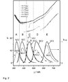
- FIG. 2 shows in the lower part the spectrally corrected and normalized emission spectra of the emission standards A to EI A ( ⁇ ) to I B ( ⁇ ) (solid lines). It can be seen that all standard spectra have a broad and unstructured band history with only one maximum and no shoulders or discontinuities in the spectral range used for the calibration.
- the greatest possible wavelength spacing was set between the maxima of the emission spectra and those of the associated absorption spectra, not shown (Stokes shift), in order to avoid the repeated absorption of once emitted photons due to Em-Abs band overlap.
- this distance for the dyes A, B, C, D and E is about 5400, 4900, 4300, 4900 and 2400 cm -1 .
- the dyes also have a low anisotropy with r ⁇ 0.05 (UV / vis spectral range with ⁇ ⁇ 700 nm) and a sufficient low temperature dependence of the shape of the fluorescence bands in the temperature range between 20 ° C and 30 ° C.
- the intensity of all spectra l i ( ⁇ ) at their respective intersection point ⁇ i / i + 1 is greater than 20% of the respective maximum (normalized) intensity.
- an intensity of at least 40% of the maximum intensities is even maintained for all overlap points.
- the half-width is according to the invention for all dyes at least in the UV / vis range greater than 1400 cm -1 .
- the half-widths of the emission spectra of compounds A to E are about 4250, 4400, 2850, 2890 and 1630 cm -1 , respectively
- the spectral range of the standard combinations presented can be improved by the integration of further dyes, e.g. said merocyanine and styryl compounds according to the above-described general structures 6, 7 and 8 are extended to the NIR spectral region.
- Analogous selection and requirement criteria apply here, wherein in the region at ⁇ > 700 nm only a minimum intensity at the overlap points of in particular at least 12% of the maximum intensity, a half-width of at least 1200 cm-1 and an anisotropy of in particular r ⁇ 0.07 are required becomes.
- the raw emission spectra of the five (or more) above-mentioned fluorescence standards A to E contained in the kit are first recorded with the fluorescence microscope to be calibrated, the focusing being carried out as described above using the focusing device (s) 24.
- the measurement conditions on the photoluminescence meter - such as gap widths, detector voltages, scan mode and speed, filters, polarizers and polarizer angles etc. - are set to the parameters under which fluorescence spectra are usually recorded or for which spectrally corrected luminescence spectra are required. Under the conditions of each dye measurement, a blank value spectrum of the solvent used is also measured in each case.
- a blank value correction is performed by subtracting the solvent spectra from the respective measured spectra to obtain the blank value corrected measured spectra J i ( ⁇ ), which are also shown in the lower part of Figure 2 as broken lines (J A ( ⁇ ) to J E ( ⁇ )).
- linking factors ⁇ i for each dye i are calculated by statistically averaging overlapping spectral ranges in the range ⁇ ⁇ by the respective overlap wavelength ⁇ i / i + 1 of all four adjacent spectra 1 i ( ⁇ ), 1 i + 1 ( ⁇ ), J i ( ⁇ ) and J i + 1 ( ⁇ ) are determined according to equations 1 to 3.
- the partial correction functions F i ( ⁇ ) are calculated implicitly according to Equation 2 by quotient of the corrected spectra l i ( ⁇ ) and the corresponding measured spectra J i ( ⁇ ) for the individual fluorescence standards i.
- the summand in equation 1 for the linking factor ⁇ i + 1 is preferably determined in each case only over a predetermined optimized spectral overlapping range ⁇ ⁇ OL by the respective overlapping wavelength ⁇ i / i + 1 .
- the statistical averaging for the calculation of ⁇ i + 1 according to Equation 1 takes place via a region of ⁇ 8 nm adjoining the respective overlap wavelengths ⁇ i / i + 1 on both sides.
- the values of the function F ( ⁇ ) in a predeterminable linking range ⁇ i / i + 1 ⁇ ⁇ LK are first determined by the respective overlap points ⁇ i / i + 1 according to equations 5 and 6.
- the linking region ⁇ i / i + 1 ⁇ ⁇ LK there is thus a statistical averaging of the mutually overlapping partial correction functions F i ( ⁇ ) weighted by ⁇ i .
- Spectra measured on a measuring system calibrated in this way under the same calibration settings are spectrally corrected by subtraction of corresponding blank value spectra by simple multiplication with the correction function F ( ⁇ ). In this way, traceable, spectrally corrected luminescence spectra are obtained in relative intensity units.
- the example described above relates to the creation of an overall correction function for the emission using emission standards. If a set of excitation standards is measured in the same way on a luminescence measuring system and the excitation spectra obtained are correspondingly calculated with a data record for the spectrally corrected (certified) excitation spectra of the fluorescence standards, a spectral excitation correction function is obtained.
- the channels 18 and the reservoirs 20 of the calibration device 10 according to FIGS. 1A to 1 D are filled with solutions of the same fluorescence standard in different concentrations. Also for this purpose, for example, the aforementioned fluorescence standards can be used.
- Such a device is suitable for determining the linearity range of the used detector system of the excitation and / or emission channel of the measuring system.
Abstract
Description
Die Erfindung betrifft eine Kalibriereinrichtung zur Charakterisierung von Lumineszenzmesssystemen, insbesondere von spektral auflösenden, Weitfeld- und/oder konfokalen Imagingsystemen, ein Kit umfassend die Kalibriereinrichtung und ein Farbstoffset sowie Verwendungen der Einrichtung oder des Kits.The invention relates to a calibrating device for characterizing luminescence measuring systems, in particular spectrally resolving, widefield and / or confocal imaging systems, a kit comprising the calibrating device and a dye set as well as uses of the device or the kit.
Jede Lumineszenzmesstechnik liefert Messdaten, die sich aus analyt- und gerätespezifischen Beiträgen zusammensetzen. Die nicht erwünschten gerätespezifischen Beiträge spiegeln die Wellenlängen- und Polarisationsabhängigkeit von Gerätekomponenten des verwendeten Messgerätes wieder. Verantwortlich für diese Abhängigkeiten sind insbesondere die im Anregungs- und Emissionskanal des Gerätes enthaltenen optischen Bauelemente, die Anregungslichtquelle und die eingesetzten Detektionssysteme. Die Vergleichbarkeit von Lumineszenzdaten über Geräte- und Laborgrenzen hinaus, die Erfassung der Gerätealterung, der Anspruch auf Rückführbarkeit von Lumineszenzdaten auf radiometrische Primärnormale (entsprechend der allgemeinen Forderung in EN ISO/IEC 17025) sowie viele quantitative Fluoreszenzaussagen, die Bestimmung von relativen Fluoreszenzquantenausbeuten und die Optimierung von Lumineszenzmethoden erfordern die Ermittlung dieser gerätespezifischen Beiträge. Dies gilt insbesondere für vergleichende Bewertungen von spektral gegeneinander verschobenen Lumineszenzprofilen oder für Emissionsmessungen bei verschiedenen Anregungswellenlängen. Bei konfokalen spektralen Imagingsystemen müssen darüber hinaus noch Geräteparameter, wie die Homogenität der Ausleuchtung, die spektrale und die Ortsauflösung (x, y, z) u.a., ermittelt werden. Ein wichtiges Einsatzgebiet konfokaler Mikroskope mit spektral auflösenden Detektoren ist das pixelweise Entmischen von einander überlappenden Farbstoffemissionen in mehrfach fluoreszenzmarkierten Präparaten. Für die Überprüfung der Robustheit gegenüber Störeinflüssen, wie z.B. schlechten Signal/Rausch-Verhältnissen und Genauigkeit der Quantifizierung bei sehr unterschiedlichen Konzentrationen gibt es bisher keine Standardpräparate.Each luminescence measurement technology provides measurement data that is composed of analyzer-specific and device-specific contributions. The unwanted device-specific contributions reflect the wavelength and polarization dependence of device components of the measuring device used. Responsible for these dependencies are in particular the optical components contained in the excitation and emission channel of the device, the excitation light source and the detection systems used. The comparability of luminescence data beyond device and laboratory boundaries, the detection of device aging, the claim to traceability of luminescence data on primary radiometric standards (according to the general requirement in EN ISO / IEC 17025) as well as many quantitative fluorescence statements, the determination of relative fluorescence quantum yields and the optimization Luminescence methods require the determination of these device-specific contributions. This applies in particular to comparative evaluations of spectral mutually shifted luminescence profiles or for emission measurements at different excitation wavelengths. In the case of confocal spectral imaging systems, device parameters, such as the homogeneity of the illumination, the spectral and the spatial resolution (x, y, z), among others, must also be determined. An important field of application of confocal microscopes with spectrally resolving detectors is the pixel-wise demixing of overlapping dye emissions in multi-fluorescence-labeled preparations. For the checking of the robustness against disturbing influences, as for example bad signal / noise ratios and accuracy of the quantification with very different concentrations there are so far no standard preparations.
Photolumineszenzmessgeräte bestehen aus einem Anregungskanal, der u.a. eine Anregungslichtquelle und ein wellenlängenselektierendes optisches Bauelement enthält und einem meist rechtwinklig zum Strahlengang des Anregungslichtes angeordneten Emissionskanal, mit dem das von dem im Probenraum befindlichen Fluorophor nach Lichtabsorption emittierte Licht (Photolumineszenz) aufgezeichnet wird. Oftmals wird über einen Strahlteiler ein definierter Teil des Anregungslichtes in einen Referenzkanal eingekoppelt, der ein optisches Bauelement wie einen Spiegel oder einen Streuer und einen (Referenz-) Detektor enthält. Mit dem Referenzkanal wird die aktuelle Anregungslichtintensität bei der Anregungswellenlänge aufgezeichnet, um so kurzzeitige Schwankungen der Anregungslichtintensität zu erfassen. Die Erfassung der oben genannten gerätespezifischen Beiträge zum Fluoreszenzsignal kann durch die Ermittlung so genannter Korrekturfunktionen erfolgen, die die Wellenlängen- und Polarisationsabhängigkeiten dieser Effekte für den Emissions- und den Anregungskanal des jeweiligen Gerätes beschreiben. Diese Korrekturfunktionen werden dabei separat ermittelt. Die Emissionskorrekturfunktion enthält dabei die wellenlängen- und polarisationsabhängige Transmissionseffizienz der optischen Bauteile im Emissionskanal und die wellenlängen- und polarisationsabhängige spektrale Empfindlichkeit des eingesetzten Detektionssystems. Die Anregungskorrekturfunktion beschreibt die wellenlängenabhängige spektrale Strahldichte der Anregungslichtquelle und die wellenlängen- und polarisationsabhängige Transmissionseffizienz der optischen Bauteile im Anregungskanal.Photoluminescence meters consist of an excitation channel, which i.a. contains an excitation light source and a wavelength-selecting optical component and a generally perpendicular to the beam path of the excitation light arranged emission channel with which the light emitted by the located in the sample chamber fluorophore light absorption (photoluminescence) is recorded. Often, a defined part of the excitation light is coupled into a reference channel via a beam splitter, which contains an optical component such as a mirror or a scatterer and a (reference) detector. With the reference channel, the current excitation light intensity is recorded at the excitation wavelength, so as to detect short-term fluctuations of the excitation light intensity. The detection of the abovementioned device-specific contributions to the fluorescence signal can be effected by the determination of so-called correction functions which describe the wavelength and polarization dependencies of these effects for the emission and excitation channels of the respective device. These correction functions are determined separately. The emission correction function contains the wavelength- and polarization-dependent transmission efficiency of the optical components in the emission channel and the wavelength- and polarization-dependent spectral sensitivity of the detection system used. The excitation correction function describes the wavelength-dependent spectral radiance of the excitation light source and the wavelength- and polarization-dependent transmission efficiency of the optical components in the excitation channel.
Bekannt ist der Einsatz zertifizierter physikalischer Transferstandards zur Erfassung der gerätespezifischen Effekte. Zur Kalibrierung des Anregungskanals kommen dabei typischerweise zertifizierte Empfängernormale zum Einsatz und für die Kalibrierung des Emissionskanals zertifizierte Standardlampen. Für den Einsatz physikalischer Transfernormale nachteilig sind die für die Anwendung notwendigen guten Optikkenntnisse des Anwenders, ihr schwieriger Einbau, kostenintensive Rekalibrierungen, brenndauerabhängige Änderungen der spektralen Strahldichte von Standardlampen, und im Falle der Emissionskorrektur mit Standardlampen die unterschiedlichen Emissionscharakteristika von Lampe und Probe und die um mindestens mehr als drei Größenordnungen unterschiedlichen spektralen Strahldichten von Transfernormal und einer typischen lumineszierenden Probe. Dies alles kann zu fehlerbehafteten und unbefriedigenden Korrekturfunktionen führen und ist zudem aufwändig und kostenintensiv.The use of certified physical transfer standards for recording the device-specific effects is known. Certified receiver standards are typically used to calibrate the excitation channel, and standard lamps certified to calibrate the emission channel. Disadvantageous for the use of physical transfer standards are the users' good optics knowledge required for the application, their difficult installation, costly recalibrations, changes in the spectral radiance of standard lamps depending on the duration of combustion, and, in the case of standard lamp emission correction, the different emission characteristics of the lamp and the sample more than three orders of magnitude different spectral radiance of Transfernormormal and a typical luminescent sample. All this can lead to faulty and unsatisfactory correction functions and is also complex and costly.
Physikalische Transferstandards sind außerdem zumeist nicht für die Kalibrierung von einfachen kompakten Photolumineszenzmesssystemen geeignet.In addition, physical transfer standards are usually not suitable for the calibration of simple compact photoluminescence measurement systems.
Für die Anregungskorrektur werden auch so genannte Quantenzähler eingesetzt. Dies sind hochkonzentrierte Farbstofflösungen, die einfallende Lichtquanten vollständig absorbieren und mit einer wellenlängenunabhängigen Fluoreszenzquantenausbeute emittieren. Quantenzähler liefern sehr konzentrations- und geometrieabhängige Messdaten und sind zudem anfällig für Polarisationseffekte. Standardisierte Kalibrierverfahren mit definierten Konzentrationen in Kombination mit definierten Messgeometrien sind für Quantenzähler nicht verfügbar.For the excitation correction also so-called quantum counters are used. These are highly concentrated dye solutions that completely absorb incident light quanta and emit wavelength-independent fluorescence quantum efficiencies. Quantum meters provide very concentration- and geometry-dependent measurement data and are also prone to polarization effects. Standardized calibration procedures with defined concentrations in combination with defined measurement geometries are not available for quantum counters.
Bekannt sind ebenfalls so genannte Fluoreszenzstandards, die typischerweise auf der Photolumineszenz einer chemischen Verbindung basieren. Spektrale Fluoreszenzstandards oder so genannte Emissions- und Anregungsstandards mit bekannten, (für gerätespezifische Effekte) korrigierten Emissions- bzw. Anregungsspektren können zur Ermittlung der spektralen Charakteristika von Photolumineszenzmesssystemen im Rahmen einer Gerätekalibrierung verwendet werden. Solche Fluoreszenzstandards werden in verschiedenen Formen eingesetzt, insbesondere in Form von Lösungen oder eingebettet in feste Polymer- oder Glasmatrizes. Vorteil von Fluoreszenzstandards, insbesondere in Form von Lösungen, ist, dass sich diese mit den zu untersuchenden lumineszierenden Proben hinsichtlich ihrer Lumineszenzintensität und Emissionscharakteristika stark ähneln. Fluoreszenzstandards erlauben somit die (spektrale) Kalibrierung unter den bei typischen Probenmessungen angewandten Bedingungen. Fluoreszenzstandards lassen sich in vielen verschiedenen Gerätetypen, Formaten und Messgeometrien vermessen und sind somit auch zur Kalibrierung von Fluoreszenzmesssystemen mit speziellen Probengeometrien oder -formaten geeignet, beispielsweise mit Mikroküvetten, Mikrotiterplatten oder Kryostatsystemen. Allein Fluoreszenzstandards erlauben die Durchführung der Kalibrierung in der selben Küvetten- und Messanordnung wie die eigentliche Probenmessung und liefern auf diese Weise optimale Kalibrierergebnisse. Problematisch bei Fluoreszenzstandards ist die Vielzahl der zu definierenden Stoff- und Lumineszenzeigenschaften. Voraussetzung für die Eignung eines Transferstandards ist die vollständige Charakterisierung aller applikationsrelevanten Eigenschaften inklusive der verwendeten Methode und der Angabe der Messunsicherheit und eine hinreichenden Langzeitstabilität im festen reinen Zustand und in Lösung bzw. eingebettet in einer Matrix.Also known are so-called fluorescence standards, which are typically based on the photoluminescence of a chemical compound. Spectral fluorescence standards or so-called emission and excitation standards with known (for device-specific effects) corrected emission or excitation spectra can be used to determine the spectral characteristics of photoluminescence measurement systems as part of a device calibration. Such fluorescence standards are used in various forms, in particular in the form of solutions or embedded in solid polymer or glass matrices. The advantage of fluorescence standards, in particular in the form of solutions, is that they are very similar to the luminescent samples to be investigated in terms of their luminescence intensity and emission characteristics. Fluorescence standards thus allow the (spectral) calibration under the conditions used in typical sample measurements. Fluorescence standards can be measured in many different device types, formats and measurement geometries and are thus also suitable for the calibration of fluorescence measurement systems with special sample geometries or formats, for example with microcuvettes, microtiter plates or cryostat systems. Only fluorescence standards allow the calibration to be carried out in the same cuvette and measuring arrangement as the actual sample measurement and thus provide optimum calibration results. The problem with fluorescence standards is the large number of substance and luminescence properties to be defined. The prerequisite for the suitability of a transfer standard is the complete characterization of all application - relevant properties including the method used and the specification of the transfer standard Measurement uncertainty and a sufficient long-term stability in the solid pure state and in solution or embedded in a matrix.
In der Fachliteratur sind zahlreiche Empfehlungen zu Fluoreszenzstandards umfassend diskutiert, auch zu Emissions- und Anregungsstandards sowie zu Fluoreszenzquantenausbeutestandards (z.B.
Der Spektralbereich, in dem ein Fluoreszenzstandard zur Kalibrierung eingesetzt werden kann, ist durch die Lage und Breite der Fluoreszenzbande limitiert, wobei im Falle von Anregungsstandards möglichst nur die langwelligste Bande eingesetzt werden sollte. Der Emissionsstandard Chininsulfat deckt z. B. nur den Spektralbereich von ca. 400 bis 550 nm ab. Um ein Photolumineszenzmesssystem im gesamten UV/vis/NIR-Spektralbereich zu kalibrieren, ist somit die Kombination mehrerer hinsichtlich ihrer Fluoreszenzspektren aufeinander abgestimmter Chromophore erforderlich. Es gibt aber bislang nur sehr wenige Beispiele für Standardkombinationen. Bekannt ist beispielsweise eine Kombination von Emissionsstandards, die aus fluorophorhaltigen Polymerfolien mit NIST-zertifizierten Emissionsspektren bestehen (
Weiterhin sind fluorophorhaltige Polymethylmethacrylat (PMMA)-Blöcke in Küvettenform als Emissions- und Anregungsstandards bekannt. Die verwendeten Fluorophore weisen i. A. stark strukturierte Emissions- und Anregungsspektren sowie steil ansteigende Flanken auf, wodurch eine nicht mehr vernachlässigbare Abhängigkeit der Fluoreszenzprofile vom Monochromatorbandpass und eine Erhöhung der Kalibrierunsicherheit entsteht. Zudem führen Unsicherheiten in der Wellenrichtigkeit so zu großen Fehlern bei der Fluoreszenzintensität. Die Spektren sind nicht rückführbar, sie sind nicht aufeinander abgestimmt und lassen sich nicht zu einer Gesamtkorrekturfunktion verknüpfen.Furthermore, fluorophore-containing polymethylmethacrylate (PMMA) blocks in cuvette form are known as emission and excitation standards. The fluorophores used have i. A. strongly structured emission and excitation spectra and steeply rising flanks, resulting in a no longer negligible dependence of the fluorescence profiles of the monochromator bandpass and an increase in the calibration uncertainty. In addition, uncertainties in the waveness lead to large errors in fluorescence intensity. The spectra are not traceable, they are not matched and can not be combined to a total correction function.
Andere bekannte Farbstofflösungen unterschiedlicher Fluorophore sind häufig mit dem Problem schmaler, steil ansteigender Emissionsbanden sowie eines unzureichenden spektralen Abstands von Absorptions- und Emissionsbande behaftet. Dies macht sie als Emissionsstandards ungeeignet. Einige Substanzen weisen zu geringe Photostabilitäten auf und bilden unter typischen Anregungs- und Messbedingungen Photoprodukte mit eigenen spektralen Beiträgen. Dies gilt besonders für ihre Anwendung in Geräten mit hohen Beleuchtungsstärken, insbesondere in Laser-basierten Messsystemen und für konfokale Fluoreszenzmikroskope. Die geringe thermische und photochemische Stabilität der meisten für makroskopische Anwendungen konzipierten Fluoreszenzstandards limitiert ihren Einsatz für Mikroskope. Viele eingesetzte Substanzen weisen eine zu große Fluoreszenzanisotropie auf, was eine zusätzliche Fehlerquelle bei der Kalibrierung bedeutet und die Verwendung von Polarisatoren erfordert. Im Allgemeinen sind die angegebenen Spektren nicht rückführbar, Angaben zur Messunsicherheit fehlen und nur in Ausnahmefällen (Chininsulfatdihydrat) sind die Spektren von einer autorisierten Stelle zertifiziert. Vielfach ist außerdem die Charakterisierung der anwendungsrelevanten spektroskopischen Eigenschaften unvollständig und Angaben zur Farbstoffreinheit fehlen in den meisten Fällen.Other known dye solutions of different fluorophores are often subject to the problem of narrow, steeply increasing emission bands as well as an insufficient spectral distance of absorption and emission bands. This makes them unsuitable as emission standards. Some substances have too low photostabilities and form photoproducts with their own spectral contributions under typical excitation and measurement conditions. This is especially true for their use in devices with high illuminance levels, especially in laser-based measurement systems and for confocal fluorescence microscopes. The low thermal and photochemical stability of most fluorescence standards designed for macroscopic applications limits their use for microscopes. Many substances used have a too large fluorescence anisotropy, which means an additional source of error in the calibration and requires the use of polarizers. In general, the reported spectra are not traceable, information on the measurement uncertainty is missing and only in exceptional cases (quinine sulfate dihydrate) are the spectra certified by an authorized body. In addition, the characterization of the application-relevant spectroscopic properties is often incomplete and information on the dye purity is missing in most cases.
Ein statistischer Ansatz zur Verknüpfung von Teilkorrekturfunktionen unterschiedlicher Farbstoffstandards zu einer Gesamtkorrekturfunktion unter Anwendung einer Zählratenstatistik (Poisson-Statistik) wird von
Neben dem ungedeckten Bedarf geeigneter Farbstoffstandards sowohl zur spektralen als auch zur quantitativen Kalibrierung vom Photolumineszenzmesssystemen bestehen im Falle konfokaler spektraler Imagingsysteme weitere Hindernisse bei der Gerätecharakterisierung. Insbesondere führen unterschiedliche Fokuseinstellungen verschiedener Anwender dazu, dass die Messung in unterschiedlichen, nicht definierten Probentiefen erfolgt. Dies führt zu kaum reproduzierbaren und artefaktischen spektralen Einflüssen, die einerseits durch Wandeffekte des Gefäßes und andererseits durch innere Auslöscheffekte des Farbstoffs hervorgerufen werden. Ein weiteres Problem in Mikroskopsystemen stellen die aufgrund der Laseranregung sehr hohen Anregungslichtintensitäten dar, welche die photochemische Degradation des Farbstoffs im Messvolumen beschleunigen uns somit zu lokalen "Ausbleicheffekten" führen. Ein bekanntes Behältersystem mit einem Mikroflusssystem zur lichtmikroskopischen und spektroskopischen Untersuchung chemischer oder biologischer Proben ist beispielsweise aus
Der Erfindung liegt daher die Aufgabe zugrunde, eine leicht bedienbare Vorrichtung zur Charakterisierung von Lumineszenzmesssystemen, insbesondere von spektral auflösenden, konfokalen und/oder Weitfeld-Imagingsystemen, zur Verfügung zu stellen, welche eine rückführbare und reproduzierbare Kalibrierung unter Verwendung von Standardlösungen erlaubt.The invention is therefore based on the object of providing an easy-to-use device for characterizing luminescence measuring systems, in particular of spectrally resolving, confocal and / or wide-field imaging systems, which permits a traceable and reproducible calibration using standard solutions.
Diese Aufgabe wird durch eine Kalibriereinrichtung mit den in Anspruch 1 genannten Merkmalen gelöst. Die erfindungsgemäße Kalibriereinrichtung zur Charakterisierung von Lumineszenzmesssystemen, insbesondere von spektral auflösenden, konfokalen und/oder Weitfeld-Imagingsystemen, umfasst
- (a) eine Grundplatte, die zumindest einen von einem Fluid durchströmbaren Kanal aufweist, wobei der zumindest eine Kanal als Probenkammer für das Lumineszenzmesssystemen ausgebildet ist,
- (b) jeweils mindestens ein, mit dem zumindest einen Kanal kommunizierendes Reservoir zur Aufnahme einer Flüssigkeit sowie
- (c) zumindest eine in die Grundplatte integrierte Fokussiereinrichtung zur Einstellung eines definierten Messstrahlfokus des zu kalibrierenden Lumineszenzmesssystems mit einer Fokussierfläche, wobei die Fokussierfläche insbesondere mit einem Innenraum des zumindest einen Kanals fluchtet, das heißt in einer Ebene liegt.
- (a) a base plate having at least one channel through which a fluid can flow, wherein the at least one channel is designed as a sample chamber for the luminescence measuring system,
- (B) in each case at least one, communicating with the at least one channel reservoir for receiving a liquid and
- (c) at least one focusing device integrated in the baseplate for setting a defined measuring beam focus of the luminescence measuring system to be calibrated with a focusing surface, the focusing surface in particular being flush with an interior of the at least one channel, that is to say lying in one plane.
Die zumindest eine integrierte Fokussierhilfe erlaubt eine verlässliche und für alle Nutzer identische Fokuseinstellung des Messstrahls (Anregungsstrahls) und damit die Vermessung praktisch identischer beleuchteter Messvolumina innerhalb der Mikrokanäle der Kalibriereinrichtung. Auf diese Weise wird gewährleistet, dass spektrale Einflüsse, die von unterschiedlichen Messtiefen verursacht werden, wie Wandeffekte oder innere Filtereffekte der in den Kanälen befindlichen Lösungen, minimiert und standardisiert werden. Somit werden reproduzierbare und über Geräte- und Laborgrenzen hinaus vergleichbare und rückführbare Messdaten erhalten.The at least one integrated focusing aid allows a reliable and for all users identical focus adjustment of the measuring beam (excitation beam) and thus the measurement of virtually identical illuminated measuring volumes within the microchannels of the calibration. In this way, it is ensured that spectral influences caused by different measurement depths, such as wall effects or internal filter effects of the solutions located in the channels, are minimized and standardized. Thus, reproducible and traceable data beyond equipment and laboratory limits are obtained.
In bevorzugter Ausführung sind zumindest zwei in die Grundplatte integrierte Fokussiereinrichtungen (Fokussierhilfen) vorgesehen, die bevorzugt auf der Grundplatte verteilt, insbesondere an einander gegenüberliegenden Randbereichen der Grundplatte angeordnet sind. Dies ermöglicht eine Erfassung einer Planarität beziehungsweise einer Abweichung von dieser und eine entsprechende Kompensation durch rechnerische Interpolation auf die Messorte der Kalibriermodule.In a preferred embodiment, at least two focusing devices (focusing aids) integrated in the base plate are provided, which are preferably distributed on the base plate, in particular on opposite edge regions of the base plate. This allows a detection of a planarity or a deviation from this and a corresponding compensation by computational interpolation on the measurement locations of the calibration.
Die Fokussiereinrichtung kann auf unterschiedliche Weise ausgeführt sein. Grundsätzlich weist sie eine hochebene Fokussierfläche auf, deren Rauheit weit unterhalb der optischen Auflösung des zu kalibrierenden Lumineszenzmesssystems liegt. Hierzu umfasst sie bevorzugt ein hochebenes Substrat, wie etwa einen Wafer aus einem Silizium-Einkristall oder dergleichen, auf dem eine sehr dünne Schicht eines reflektierenden und/oder fluoreszierenden Materials aufgesputtert ist. Hierfür eignet sich beispielsweise eine dünne Metallschicht (z.B. Chromschicht) mit einer Schichtdicke zwischen 10 und 100 nm, insbesondere zwischen 30 und 50 nm. Alternativ oder zusätzlich kann die Fokussierfläche lumineszierend, insbesondere fluoreszierend ausgebildet sein. Neben üblichen fluoreszierenden Materialien sind insbesondere fluoreszierende Quantumdots bevorzugt, die sich durch eine besonders hohe Stabilität auszeichnen. Besonders bevorzugt werden unterschiedliche fluoreszierende Materialien auf einem oder verschiedenen Wafern eingesetzt, deren unterschiedliche spektrale Eigenschaften typische Anregungs- oder Emissions-Spektralbereich des betreffenden Messsystems abdecken. Auf diese Weise erlaubt die Fokussiereinrichtung unter anderem eine Bestimmung der Parfokalität (hierunter versteht man ein über die Objektivabgleichlänge erzeugte identische Schärfeneinstellung) eines verwendeten Objektivs des Messsystems und einen parfokalen Bildabgleich mittels rechnerischer Methoden oder durch die Verwendung von Hilfslinsen im Mikroskop.The focusing device can be designed in different ways. Basically, it has a high-level focusing surface whose roughness is far below the optical resolution of the luminescence measuring system to be calibrated. For this purpose, it preferably comprises a high-level substrate, such as a wafer of a silicon monocrystal or the like, on which a very thin layer of a reflective and / or fluorescent Sputtered on material. For this purpose, for example, a thin metal layer (eg chromium layer) with a layer thickness between 10 and 100 nm, in particular between 30 and 50 nm is suitable. Alternatively or additionally, the focusing surface may be formed luminescent, in particular fluorescent. In addition to conventional fluorescent materials, fluorescent quantum dots are particularly preferred, which are characterized by a particularly high stability. Particular preference is given to using different fluorescent materials on one or different wafers whose different spectral properties cover typical excitation or emission spectral range of the relevant measuring system. In this way, the focusing device allows, inter alia, a determination of the parfocality (this is understood to mean an identical sharpness setting produced via the objective alignment length) of a used objective of the measuring system and a parfocal image matching by means of computational methods or by the use of auxiliary lenses in the microscope.
Durch die Reservoire, von denen in bevorzugter Ausführung jeweils zwei, beidseitig mit einem Kanal verbunden vorgesehen sind, wird eine gute Langzeitstabilität gewährleistet, da Moleküle im Messvolumen, die infolge der in der Fluoreszenzmikroskopie typischerweise eingesetzten sehr hohen Strahlenintensität am Probenort (Laseranregung) durch thermische und/oder photochemische Prozesse zersetzt werden, durch Diffusionsprozesse aus den Reservoiren kontinuierlich ersetzt werden. Hierfür sind die Volumina der Reservoire sowie die Abmessungen der Kanäle so gewählt, dass ausreichende Diffusionsgeschwindigkeiten vorliegen. Zudem ist vorzugsweise das durch die Kanal/Reservoir-Einheit ausgebildete Mikroflusssystem vollständig luftdicht verschließbar, um Oxidationsprozesse der Proben und Verdunstung des verwendeten Lösungsmittels zu verhindern.By the reservoirs, of which two in a preferred embodiment, both sides are provided with a channel, a good long-term stability is ensured because molecules in the measurement volume, due to the typically used in fluorescence microscopy very high radiation intensity at the sample site (laser excitation) by thermal and / or photochemical processes are decomposed, continuously replaced by diffusion processes from the reservoirs. For this purpose, the volumes of the reservoirs and the dimensions of the channels are chosen so that there are sufficient diffusion rates. In addition, preferably, the microfluid system formed by the channel / reservoir unit is completely hermetically sealed in order to prevent oxidation processes of the samples and evaporation of the solvent used.
Das Kalibriersystem wird hinsichtlich seiner Abmessungen (Größe der Grundplatte, Durchmesser und Abstand der (Mikro)Kanäle, Größe des Reservoirs) und seinem Material (Glas, Quarzglas, Kunststoff) sowie der Ausgestaltung und Positionierung der Fokussiereinrichtung(en) an das zu kalibrierende Lumineszenzmesssystem angepasst, beispielsweise an ein spektral auflösendes Weitfeld-Imagingsystem oder ein spektral auflösendes konfokales Fluoreszenzmikroskop. Für Applikationen im Zusammenhang mit Kalibrierungen von spektral auflösenden konfokalen Fluoreszenzmikroskopen wird durch die Integration der Fokussierhilfen, etwa an beiden Seiten einer Kalibriereinrichtung mit typischen Dimensionen von Mikroskopobjektträgern erreicht, dass jeder Anwender nahezu das gleiche beleuchtete Volumen der Farbstofflösungen vermisst, was eine vergleichbare und reproduzierbare Gerätecharakterisierung und der damit erhaltenen Messdaten unter applikationsrelevanten, also probenspezifischen Messbedingungen ermöglicht.With regard to its dimensions (size of the base plate, diameter and spacing of the (micro) channels, size of the reservoir) and its material (glass, quartz glass, plastic) as well as the configuration and positioning of the focusing device (s), the calibration system is adapted to the luminescence measuring system to be calibrated , For example, to a spectrally resolving wide-field imaging system or a spectrally resolving confocal fluorescence microscope. For applications related to calibrations of spectrally resolving confocal fluorescence microscopes, the integration of focusing aids, For example, on both sides of a calibration device with typical dimensions of microscope slides, each user measures almost the same illuminated volume of the dye solutions, which enables comparable and reproducible device characterization and the measurement data thus obtained under application-relevant, thus sample-specific measurement conditions.
Nach einer bevorzugten Ausgestaltung der Erfindung ist der zumindest eine Kanal und/oder das mindestens eine diesem Kanal zugeordnete Reservoir mit einem Fluoreszenzstandard zumindest teilweise befüllt. In noch weiter bevorzugter Ausführung weist die Grundplatte eine Mehrzahl von Kanälen und diesen zugeordneten Reservoiren auf, wobei die Kanäle und/oder die zugeordneten Reservoire mit unterschiedlichen Fluoreszenzstandards zumindest teilweise befüllt sind.According to a preferred embodiment of the invention, the at least one channel and / or the at least one reservoir associated with this channel is at least partially filled with a standard of fluorescence. In a further preferred embodiment, the base plate has a plurality of channels and associated reservoirs, wherein the channels and / or the associated reservoirs are at least partially filled with different fluorescence standards.
Grundsätzlich kann die erfindungsgemäße Kalibriereinrichtung applikationsadaptiert mit verschiedenen problemspezifisch ausgewählten, zuvor spektroskopisch charakterisierten Farbstofflösungen befüllt sein. Dabei ist besonders vorteilhaft vorgesehen, dass die Fluoreszenzstandards derart gewählt sind, dass ihre spektral korrigierten Fluoreszenzspektren zusammen einen vorgegebenen Spektralbereich mit einer vorgegebenen Mindestintensität abdecken, so dass die Verrechnung der von diesen gemessenen Spektren mit den entsprechenden korrigierten, vorzugsweise zertifizierten Spektren eine Gesamtkorrekturfunktion liefert, die eine Kalibrierung des Messsystems für einen weiten Spektralbereich erlaubt. Die Ermittlung einer Gesamtkorrekturfunktion erfolgt im Wesentlichen durch Messung der Fluoreszenzspektren der Fluoreszenzstandards, Berechnung von Teilkorrekturfunktionen als Quotienten der gemessenen und den entsprechenden korrigierten (idealerweise zertifizierten) Fluoreszenzspektren und Verknüpfung der Teilkorrekturfunktionen zu einer Gesamtkorrekturfunktion unter Verwendung statistischer Methoden. Ein besonders bevorzugtes Verfahren zur Berechnung einer solchen Gesamtkorrekturfunktion sowie bevorzugte Sets derart aufeinander abgestimmter Fluoreszenzstandards sind in der älteren Anmeldung
Besonders bevorzugte Fluoreszenzstandards für die Bestimmung der relativen spektralen Empfindlichkeit von Detektionssystemen (Emission oder Anregung) sind in nachfolgend näher erläuterter Weise hinsichtlich verschiedener Eigenschaften der Substanzen und ihrer spektralen Eigenschaften aufeinander abgestimmt. Hierzu zählt zunächst eine einzuhaltende relative Mindestintensität an den einzelnen Überschneidungswellenlängen jeweils zwei spektral benachbarter Fluoreszenzbanden zweier Standards. Diese Mindestintensität beträgt mindestens 20 % der maximalen Intensität der Banden, insbesondere von mindestens 25 %, vorzugsweise mit mindestens 30 % der maximalen Bandenintensität. In konkreten Ausführungsbeispielen liegen diese Intensitäten sogar bei etwa 40 % der maximalen Bandenintensität. Die vorgenannten Werte beziehen sich auf den UV/vis-Spektralbereich mit λ ≤ 700 nm. Da im NIR-Bereich mit λ, > 700 nm grundsätzlich geringere Quantenausbeuten und damit geringere absolute Intensitäten vorliegen, können in diesem Bereich geringere Mindestintensitäten an den Überschneidungspunkten von mindestens 10 %, insbesondere bei etwa 15 %, vorzugsweise etwa 25 % der Maximalintensität der jeweiligen flankierenden Bande zugelassen werden. Es wird somit sichergestellt, dass im gesamten Spektralbereich ausschließlich hohe Intensitäten in die Statistik zur Berechnung einer Gesamtkorrekturfunktion für das zu kalibrierende Messsystem einfließen, wodurch sich eine hohe Zuverlässigkeit bzw. geringe Unsicherheit ergibt. Unter Zugrundelegung der geforderten Mindestintensitäten decken die aufeinander abgestimmten Fluoreszenzstandards vorzugsweise einen vorgegebenen Spektralbereich im UV/vis/NIR-Bereich zumindest teilweise ab. Insbesondere überdeckt ein Set von Emissionsstandards für eine Emissionskorrektur einen Bereich von 310 bis 730 nm ab, bevorzugt von 300 bis 950 nm, wobei für Mikroskopieanwendungen insbesondere ein Bereich von 400 bis 800 nm relevant ist. Ein vorteilhaftes Set von Anregungsstandards für eine Anregungskorrektur einen Bereich von 280 bis 600 nm, bevorzugt von 240 bis 800 nm.Particularly preferred fluorescence standards for the determination of the relative spectral sensitivity of detection systems (emission or excitation) are described in more detail below with regard to various properties of the substances and their properties spectral properties matched. This firstly includes a relative minimum intensity to be maintained at the individual overlap wavelengths of two spectrally adjacent fluorescence bands of two standards. This minimum intensity is at least 20% of the maximum intensity of the bands, in particular of at least 25%, preferably at least 30% of the maximum band intensity. In concrete embodiments, these intensities are even at about 40% of the maximum band intensity. The abovementioned values relate to the UV / vis spectral range with λ ≦ 700 nm. Since generally lower quantum yields and therefore lower absolute intensities are present in the NIR range with λ,> 700 nm, lower minimum intensities at the intersecting points of at least 10%, in particular about 15%, preferably about 25% of the maximum intensity of the respective flanking band are allowed. It is thus ensured that exclusively high intensities are included in the statistics in the entire spectral range for calculating an overall correction function for the measuring system to be calibrated, resulting in a high level of reliability or low uncertainty. On the basis of the required minimum intensities, the coordinated fluorescence standards preferably at least partially cover a predetermined spectral range in the UV / vis / NIR range. In particular, a set of emission standards for emission correction covers a range of 310 to 730 nm, preferably 300 to 950 nm, with a range of 400 to 800 nm being particularly relevant for microscopy applications. An advantageous set of excitation standards for excitation correction ranges from 280 to 600 nm, preferably from 240 to 800 nm.
Gemäß einer weiteren bevorzugten Ausgestaltung der Erfindung weisen sämtliche Fluoreszenzstandards Fluoreszenzbanden im UV/vis-Spektralbereich mit λ ≤ 700 nm mit einer Halbwertsbreite (FWHM) zumindest von 1600 cm-1, insbesondere von zumindest 2000 cm-1, vorzugsweise von mindestens 2400 cm-1 auf und im NIR-Bereich mit λ > 700 nm von mindestens 1200 cm-1 insbesondere mindestens 1400 cm-1. Die erfindungsgemäße Zusammenstellung des (bzw. der) Kits versetzt einen Benutzer in die Lage, eine Kalibrierung des Messsystems zuverlässig, reproduzierbar und preiswert durchzuführen. Insbesondere die erfindungsgemäße Abstimmung der einzelnen Fluoreszenzstandards, insbesondere ihrer Halbwertsbreiten sowie die geforderte Mindestintensität an den Überschneidungswellenlängen, ermöglicht die Erzeugung einer Gesamtkorrekturfunktion für das Gerät über einen weiten Spektralbereich in bislang nicht verfügbarer Qualität.According to another preferred embodiment of the invention, all fluorescence standards fluorescence bands in the UV / vis spectral range with λ ≤ 700 nm with a half-width (FWHM) of at least 1600 cm -1 , in particular of at least 2000 cm -1 , preferably of at least 2400 cm -1 on and in the NIR range with λ> 700 nm of at least 1200 cm -1, in particular at least 1400 cm -1 . The inventive composition of the (or the) kit enables a user to perform a calibration of the measuring system reliable, reproducible and inexpensive. In particular, the tuning according to the invention of the individual fluorescence standards, in particular their half-widths and the required minimum intensity at the overlap wavelengths, enables the generation of a total correction function for the device over a wide spectral range in previously unavailable quality.
Neben der geforderten Mindestintensität der Fluoreszenzspektren an den Überschneidungspunkten und der Mindesthalbwertsbreite erfüllen nach weiteren Ausgestaltungen der Erfindung sämtliche Fluoreszenzstandards weitere im Folgenden beschriebene Anforderungen. Nach einer besonders vorteilhaften Ausgestaltung der Erfindung sind alle Farbstoffstandards so gewählt, dass ihre Lumineszenzbanden einen glatten und unstrukturierten Bandenverlauf aufweisen, d.h. bei einer spektralen Auflösung von 1 nm weisen die Banden nur ein Maximum, keine Schultern sowie einen stetigen Bandenverlauf auf. Ebenso wie die geforderte minimale Halbwertsbreite, die mit einer flachen Flankensteilheit der Banden einhergeht, garantiert auch der unstrukturierte und glatte Verlauf der Banden eine bestmögliche Unabhängigkeit der gemessenen Spektren von den Messbedingungen sowie der Geräteausstattung bzw. den Parametereinstellungen des verwendeten Spektrometers, insbesondere von Monochromatorbandpass und -spaltbreite des Messkanals. Die erfindungsgemäßen Bandencharakteristika führen somit zu einer Erhöhung der Kalibriersicherheit.In addition to the required minimum intensity of the fluorescence spectra at the points of intersection and the minimum half-width, according to further embodiments of the invention, all fluorescence standards fulfill further requirements described below. According to a particularly advantageous embodiment of the invention, all dye standards are chosen so that their luminescence bands have a smooth and unstructured band profile, i. At a spectral resolution of 1 nm, the bands have only a maximum, no shoulders and a continuous band history. As well as the required minimum half-width, which is accompanied by a flat slope of the bands, the unstructured and smooth course of the bands also guarantees the best possible independence of the measured spectra from the measurement conditions and the instrumentation or parameter settings of the spectrometer used, in particular monochromator bandpass and gap width of the measuring channel. The band characteristics according to the invention thus lead to an increase in calibration reliability.
Es ist ferner vorgesehen, sämtliche Farbstoffstandards mit einer Reinheit von mindestens 98 %, vorzugsweise von mindestens 99,5 % bereitzustellen. Ferner sollte jeder Farbstoffstandard eine geringe Überlappung seiner Anregungs- und Emissionsbande aufweisen. Insbesondere besteht ein bevorzugter Abstand zwischen Anregungs- und Emissionsbanden von mindestens 2000 cm-1, insbesondere mindestens 2400 cm-1 und im Idealfall von mindestens 2800 cm-1. Die Farbstoffstandards sollten darüber hinaus in einem Temperaturbereich von 20 bis 30 °C eine Anisotropie der Fluoreszenz im zu verwendenden Lösungsmittel im UV/vis-Spektralbereich mit λ ≤ 700 nm von höchstens 0,05 und vorzugsweise von höchstens 0,04 aufweisen, im NIR-Spektralbereich von höchstens 0,15 und vorzugsweise von höchstens 0,07. Weitere Fehlerquellen der Kalibrierung werden dadurch vermieden, dass die vorgeschlagenen Farbstoffstandards im typischen Messtemperaturbereich von 20 bis 30 °C keine oder nur eine geringe Temperaturabhängigkeit der spektralen Form der Fluoreszenzspektren aufweisen. Die Farbstoffe sind ferner durch eine hohe thermische und photochemische Stabilität ihrer Reinstoffe und auch ihrer Lösungen gekennzeichnet. Weiterhin ist ein Homogenität der Standardlösungen wichtig, die bis zur maximalen Ortsauflösung des Messsystems ortsunabhängige Fluoreszenzspektren garantiert. Schließlich ist gewährleistet, dass die Farbstoffstandards unter für statische Photolumineszenzmessungen typischen Mess- und Anregungsbedingungen keine Photoprodukte bilden, die eigene spektrale Beiträge im relevanten Spektralbereich aufweisen. Insbesondere weisen sie einen maximal 10%igen, vorzugsweise maximal 2%igen Abbau der Fluoreszenzbanden bei 5-stündiger Einstrahlung des Lichts einer 150 W-Xenon-Höchstdrucklampe im Bereich des längstwelligen Absorptionsmaximums bei einer Breite des Bandpasses von ca. 15 nm auf, so dass die thermische und photochemische Stabilität ausreichend für die geplanten Anwendungen ist. Auf der anderen Seite sorgen die Reservoire und die damit verbundenen Diffusionsprozesse - im Falle dennoch auftretender photochemischer Prozesse - für einen Ersatz der betroffenen Moleküle durch unzerstörte Farbstoffmoleküle im Messvolumen. Insbesondere die Gesamtheit der genannten spektroskopischen und chemischen Eigenschaften der Fluoreszenzstandards gewährleistet eine hohe Kalibriersicherheit und eine Rückführbarkeit nach EN ISO/IEC 17025.It is further contemplated to provide all dye standards having a purity of at least 98%, preferably at least 99.5%. Furthermore, each dye standard should have little overlap in its excitation and emission bands. In particular, there is a preferred distance between excitation and emission bands of at least 2000 cm -1 , in particular at least 2400 cm -1, and ideally at least 2800 cm -1 . The dye standards should moreover have an anisotropy of the fluorescence in the solvent to be used in the UV / vis spectral range with λ ≦ 700 nm of not more than 0.05 and preferably of not more than 0.04 in the temperature range from 20 to 30 ° C., in the NIR range. Spectral range of at most 0.15 and preferably at most 0.07. Further error sources of the calibration are avoided in that the proposed dye standards in the typical measurement temperature range of 20 to 30 ° C have no or only a small temperature dependence of the spectral shape of the fluorescence spectra. The dyes are also characterized by a high thermal and photochemical stability of their pure substances and also their solutions. Furthermore, a homogeneity of the standard solutions is important which guarantees up to the maximum spatial resolution of the measuring system location-independent fluorescence spectra. Finally, it is ensured that the dye standards do not form photoproducts under spectral measurements and excitation conditions typical for static photoluminescence measurements, which have their own spectral contributions in the relevant spectral range. In particular, they have a maximum of 10%, preferably a maximum of 2% degradation of the fluorescence bands at 5-hour irradiation of the light of a 150 W xenon high pressure lamp in the region of the longest wavelength absorption maximum at a width of the bandpass of about 15 nm, so that the thermal and photochemical stability is sufficient for the intended applications. On the other hand, the reservoirs and the associated diffusion processes - in the case of nonetheless occurring photochemical processes - provide for a replacement of the affected molecules by undestroyed dye molecules in the measurement volume. In particular, the entirety of the stated spectroscopic and chemical properties of the fluorescence standards ensures high calibration reliability and traceability according to EN ISO / IEC 17025.
Die Kalibriereinrichtung kann grundsätzlich eine Mehrzahl unterschiedlicher Emissionsstandards (und vorzugsweise deren spektral korrigierte Emissionsspektren) zur Erstellung einer Gesamtkorrekturfunktion für den Emissionskanal (Emissionskorrekturfunktion) enthalten als auch eine Mehrzahl unterschiedlicher Anregungsstandards (und vorzugsweise deren korrigierte Anregungsspektren) zur Erstellung einer Gesamtkorrekturfunktion für den Anregungskanal (Anregungskorrekturfunktion) umfassen.The calibration device can basically contain a plurality of different emission standards (and preferably their spectrally corrected emission spectra) for generating an overall correction function for the emission channel (emission correction function) as well as a plurality of different excitation standards (and preferably their corrected excitation spectra) for generating an overall correction function for the excitation channel (excitation correction function). include.
Ein Set bevorzugter Emissionsstandards enthält insbesondere aus der Gruppe der Biphenyl-, Naphthalin-, Coumarin-, Oxazin-, Merocyanin-, Hemicyanin- und Styryl-Derivate ausgewählte Verbindungen. Als Anregungsstandards werden bevorzugt Derivate aus der Gruppe enthaltend Biphenyl-, Terphenyl-, Oxadiazol-, Coumarin-, Oxazin-, Merocyanin-, Hemicyanin- und Styryl-Derivate ausgewählt. Nachfolgend werden einige explizite Emissions- und oder Anregungsstandards aufgeführt, die den vorstehend genannten Kriterien entsprechen.A set of preferred emission standards contains, in particular, compounds selected from the group of biphenyl, naphthalene, coumarin, oxazine, merocyanine, hemicyanine and styryl derivatives. Preferred excitation standards are derivatives selected from the group consisting of biphenyl, terphenyl, oxadiazole, coumarin, oxazine, merocyanine, hemicyanine and styryl derivatives. The following are some explicit emission and / or excitation standards that meet the above criteria.
Ein erster bevorzugter Emissions- und/oder Anregungsstandard ist ein Biphenylderivat nach der allgemeinen Formel 1

Ein zweiter bevorzugter Emissions- und/oder Anregungsstandard ist ein Naphthalinderivat nach der allgemeinen Formel 2

Ein dritter bevorzugter Emissions- und/oder Anregungsstandard ist ein Cumarinderivat nach der allgemeinen Formel 3

Ein vierter bevorzugter Emissions- und/oder Anregungsstandard ist ein Cumarinderivat nach der allgemeinen Formel 4

Ein fünfter Emissions- und/oder Anregungsstandard ist ein Oxazinderivat, insbesondere ein 3H-Phenoxazin-5-onderivat nach der allgemeinen Formel 5

Ein sechster Emissions- und/oder Anregungsstandard ist ein Merocyaninderivat nach der allgemeinen Formel 6

Ein weiterer Emissions- und/oder Anregungsstandard ist ein Styrylderivat, insbesondere ein Hemicyaninderivat nach der allgemeinen Formel 7

Ein weiterer Emissions- und/oder Anregungsstandard ist ein Styrylderivat, insbesondere ein Hemicyaninderivat nach der allgemeinen Formel 8

Ein weiterer bevorzugter Emissions- und/oder Anregungsstandard ist p-Terphenyl nach der allgemeinen Formel 9

Ein weiterer bevorzugter Emissions- und/oder Anregungsstandard ist ein 1,3,4-Oxadiazolderivat nach Formel 10

Eine Kalibriereinrichtung gemäß einer besonders bevorzugten Ausgestaltung umfasst ein Set von Emissionsstandards, der jeweils einen Fluoreszenzstandard nach den allgemeinen Formeln 1 bis 5 enthält. Ein solches Set deckt den Spektralbereich von etwa 310 bis 730 nm ab. Zusätzlich kann dieses Set für den Emissionskanal mindestens einen weiteren Emissionsstandard, ausgewählt aus den allgemeinen Formeln 6, 7 und 8 umfassen, um somit die Erstellung einer Gesamtkorrekturfunktion für einen Bereich von ca. 310 bis 950 nm zu ermöglichen.A calibration device according to a particularly preferred embodiment comprises a set of emission standards, each containing a fluorescence standard according to the
Eine besonders bevorzugte Kalibriereinrichtung zur Erstellung einer Gesamtkorrekturfunktion für den Anregungskanal umfasst ein Set von Anregungsstandards, das jeweils einen Anregungsstandard nach den allgemeinen Formeln 3, 4, 5, 9 und 10 enthält.A particularly preferred calibration device for generating an overall correction function for the excitation channel comprises a set of excitation standards, each containing an excitation standard according to the
Ein weiterer Aspekt der vorliegenden Erfindung betrifft ein Kit, das eine erfindungsgemäße (unbefüllte) Kalibriereinrichtung gemäß der vorstehenden Beschreibung sowie ein Set unterschiedlicher Fluoreszenzstandards als Lösung oder Feststoff umfasst. Vorzugsweise weist das Set von Fluoreszenzstandards die vorstehend erläuterten Eigenschaften auf und ist aus den vorstehend beschriebenen Substanzen gewählt. Nach einer weiteren bevorzugten Ausgestaltung umfasst das Kit ferner korrigierte Fluoreszenzspektren der im Kit enthaltenen Fluoreszenzstandards in computerlesbarer Form und/oder eine Angabe einer Internetseite, auf welcher die korrigierten Fluoreszenzspektren abrufbar sind. Es ist ferner vorteilhaft vorgesehen, dass das Kit darüber hinaus einen Programmalgorithmus zur Berechnung einer Gesamtkorrekturfunktion für einen vorgegebenen Spektralbereich enthält und/oder eine Angabe einer Internetseite, auf welcher das Programm abrufbar ist. Ein geeigneter Algorithmus ist etwa in der älteren Anmeldung
Die erfindungsgemäße Kalibriereinrichtung bzw. das Kit werden bevorzugt zur relativen spektralen Kalibrierung von Photolumineszenzmessgeräten, insbesondere zur Bestimmung gerätespezifischer spektraler Beiträge zu Messdaten verwendet. Daneben kann die Kalibriereinrichtung bzw. das Kit aber auch als Fluoreszenzquantenausbeutestandard zur Bestimmung von relativen Fluoreszenzquantenausbeuten im UV/vis/NIR-Spektralbereich verwendet werden, das heißt zur quantitativen Kalibrierung der Intensitäten. Dabei ist die Fluoreszenzquantenausbeute definiert als das Verhältnis der von einer Probe emittierten Anzahl von Photonen zu der von der Probe absorbierten Photonenanzahl. Ferner ist denkbar, das Kit bzw. seine Farbstoffstandards zur Bestimmung des Linearitätsbereichs eines Detektionssystems eines Photolumineszenzmesssystems einzusetzen. Dabei wird der Bereich eines Detektors bestimmt, in dem die von diesem angezeigte Intensität linear mit der eingestrahlten Intensität zunimmt, das heißt in dem eine zuverlässige quantitative Aussage über eine Konzentration eines Chromophors in der Probe möglich ist. In diesem Fall werden die Kanäle der Kalibriereinrichtung mit verschiedenen Konzentrationen von ein und demselben Fluoreszenzstandard befüllt. Darüber hinaus eignet sich die Kalibriereinrichtung zur Charakterisierung der Langzeitstabilität und von tagesabhängigen Performanceschwankungen hinsichtlich der Messintensitäten des Messsystems ("day-to-day instrument performance") sowie zum Vergleich von Lumineszenzmesssystemen untereinander. Weitere Anwendungsgebiete sind die Charakterisierung der Homogenität der Ausleuchtung bei verschiedenen Anregungs- und Emissionswellenlängen, die Vergleichbarkeit von Lumineszenzdaten und - intensitäten, die Ermittlung der relativen spektralen Beleuchtungsstärke am Probenort sowie spektrales Unmixing und die Überprüfung von für diese Zwecke eingesetzte Auswertungssoftware.The calibration device or the kit according to the invention are preferably used for the relative spectral calibration of photoluminescence measuring devices, in particular for determining device-specific spectral contributions to measured data. In addition, however, the calibration device or the kit can also be used as fluorescence quantum yield standard for the determination of relative fluorescence quantum yields in the UV / vis / NIR spectral range, that is for the quantitative calibration of the intensities. The fluorescence quantum yield is defined as the ratio of the number of photons emitted by a sample to the number of photons absorbed by the sample. Furthermore, it is conceivable to use the kit or its dye standards for determining the linearity range of a detection system of a photoluminescence measuring system. In this case, the range of a detector is determined, in which the intensity displayed by this increases linearly with the irradiated intensity, that is, in which a reliable quantitative statement about a concentration of a chromophore in the sample is possible. In this case, the channels of the calibration device are filled with different concentrations of one and the same standard of fluorescence. In addition, the calibration device is suitable for characterizing the long-term stability and daily-dependent performance fluctuations with regard to the measuring intensities of the measuring system ("day-to-day instrument performance") and for comparing luminescence measuring systems with one another. Further fields of application are the characterization of the homogeneity of the illumination at different excitation and emission wavelengths, the comparability of luminescence data and intensities, the determination of the relative spectral illuminance at the sample location as well as Spectral unmixing and verification of evaluation software used for this purpose.
Die Kalibriereinrichtung kann je nach Format und Größe sowie Anordnung der Kanalstrukturen zur Charakterisierung vieler verschiedener Typen von Photolumineszenzmesssystemen eingesetzt werden, beispielsweise konfokalen spektral auflösenden Imagingsystemen, wie konfokalen Fluoreszenzmikroskopen und Mikroarrayscannern, wide-field Fluoreszenzmikroskopen sowie Ramanspektrometern und Ramanmikroskopen. Sie kann für verschiedene Messgeometrien eingesetzt werden. Durch Wahl der eingefüllten Farbstoffe und Farbstoffkombinationen ist eine weite Problemanpassung möglich, z.B. an gerätespezifische Anregungswellenlängen und detektierbare Emissionsspektralbereiche sowie an unterschiedliche Signalgrößen bzw. Fluoreszenzintensitäten oder den Intensitätsverhältnissen. Die erfindungsgemäße Kalibriereinrichtung ist auf die Handhabung durch technisches Personal zugeschnitten.Depending on the format and size and arrangement of the channel structures, the calibration device can be used to characterize many different types of photoluminescence measurement systems, for example confocal spectral resolution imaging systems such as confocal fluorescence microscopes and microarray scanners, wide-field fluorescence microscopes and Raman spectrometers and Raman microscopes. It can be used for different measuring geometries. By choosing the charged dyes and dye combinations, a wide problem adaptation is possible, e.g. to device-specific excitation wavelengths and detectable emission spectral regions and to different signal sizes or fluorescence intensities or the intensity ratios. The calibration device according to the invention is tailored to handling by technical personnel.
Weitere bevorzugte Ausgestaltungen der Erfindung ergeben sich aus den übrigen, in den Unteransprüchen genannten Merkmalen.Further preferred embodiments of the invention will become apparent from the remaining, mentioned in the dependent claims characteristics.
Die Erfindung wird nachfolgend in Ausführungsbeispielen anhand der zugehörigen Zeichnungen näher erläutert. Es zeigen:
- Figur 1A
- Unteransicht einer erfindungsgemäßen Kalibriereinrichtung;
- Figur 1B
- Oberansicht der erfindungsgemäßen Kalibriereinrichtung aus Figur 1A;
- Figur 1C
- Längsschnitt der erfindungsgemäßen Kalibriereinrichtung gemäß der Schnittansicht in Figur 1B;
- Figur 1D
- Querschnitt der erfindungsgemäßen Kalibriereinrichtung gemäß der Schnittansicht in Figur 1C; und
Figur 2- korrigierte (zertifizierte) und gemessene Emissionsspektren von Farbstoffstandards A bis E sowie daraus berechnete Teilkorrekturfunktionen und Gesamtkorrekturfunktion.
- Figure 1A
- Bottom view of a calibration device according to the invention;
- FIG. 1B
- Top view of the calibration device according to the invention from FIG. 1A;
- Figure 1C
- Longitudinal section of the calibration device according to the invention according to the sectional view in Figure 1B;
- FIG. 1D
- Cross section of the calibration device according to the invention according to the sectional view in Figure 1C; and
- FIG. 2
- corrected (certified) and measured emission spectra of dye standards A to E and the partial correction functions and overall correction function calculated from them.
Figuren 1A bis 1 B zeigen verschiedene Ansichten einer insgesamt mit 10 bezeichneten erfindungsgemäßen Kalibriereinrichtung gemäß einer vorteilhaften Ausgestaltung der Erfindung zur Kalibrierung insbesondere eines konfokalen Fluoreszenzmikroskops. Die Kalibriereinrichtung 10 umfasst eine flächige Grundplatte 12 mit einer Unterseite 14 und einer Oberseite 16. Die Grundplatte 12 kann aus einem geeigneten Polymer, Glas oder Quarzglas bestehen und ein- oder mehrstückig, auch unter Verwendung unterschiedlicher Materialien hergestellt sein. Die Abmessungen der Grundplatte 12 betragen gemäß dem gezeigten Beispiel 76,0 mm X 26,0 mm und entsprechen damit Standardabmessungen von Objektträgern für Mikroskope.FIGS. 1A to 1 B show various views of a calibration device according to the invention designated as a whole according to an advantageous embodiment of the invention for calibrating, in particular, a confocal fluorescence microscope. The
Die Kalibriereinrichtung 10 weist eine Mehrzahl von (hier fünf) Kanälen 18 auf, welche die Grundplatte 12 parallel zur Unter- und Oberseite 14, 16 sowie zu den seitlichen Begrenzungen der Grundplatte 12 durchsetzen und in einem definierten äquidistanten Abstand zueinander angeordnet sind. Sie verlaufen nahe an derjenigen Grundfläche, welche dem Messstrahl des zu kalibrierenden Lumineszenzmesssystems zugewandt ist, hier der Unterseite 14. Aus herstellungstechnischen Gründen können die Kanäle 18 auch als Furchen in die Grundplatte 12 eingearbeitet und durch eine optisch durchlässige, auf die Grundplatte 12 aufgeklebte oder aufgeschweißte Folie verschlossen sein. Wie am besten aus Figur 1 D hervorgeht, treten die Kanäle 18 beidseitig auf die Oberfläche 6der Grundplatte 12 aus, wo sie in Reservoire 20 münden. Jedem Kanal 18 sind somit zwei, auf der Oberseite 16 der Grundplatte 12 angeordnete Reservoire 20 zugeordnet, die beispielsweise als Hohlzylinder oder dergleichen ausgestaltet sind. Die Reservoire 20 sind luftdicht verschließbar, beispielsweise mit hier nicht dargestellten, aufsteckbaren Deckeln.The
Die Innenräume der Kanäle 18 bilden die eigentlichen Proben- beziehungsweise Messkammern für das Lumineszenzmesssystemen aus, das heißt zur Messung der Lumineszenzeigenschaften einer in einem Kanal 18 befindlichen Probe wird der Messstrahl in den Innenraum des Kanals 18 fokussiert. Hierfür weisen die Kanäle 18 bevorzugt eine rechteckigen Querschnitt (Figur 1 C) beispielweise mit einer Höhe von 0,4 mm, einer Breite von 3,8 mm und einer Länge von 17,0 mm auf. Die Durchmesser der (Mikro)Kanäle 18 und die Reservoirgröße sind so bemessen, dass über Diffusionsprozesse ständig neue Farbstoffmoleküle an den Messort gelangen und somit photochemisch oder thermisch zersetzte Moleküle ersetzen.The interiors of the
Die Kanäle 18 sowie die mit diesen kommunizierende Reservoire 20 sind mit Lösungen unterschiedlicher Fluoreszenzfarbstoffstandards 22 gefüllt - bildlich angedeutet durch unterschiedliche Graustufen der Lösungen. Dabei bilden die in jeweils zwei Reservoire 20 stehende Flüssigkeitssäulen ein über einen Kanal 18 hydrostatisch kommunizierendes System. Bei den Fluoreszenzstandards 22 handelt es sich beispielsweise um ein Set aufeinander abgestimmter Emissionsstandards zur Kalibrierung des Emissionskanals des Messsystems oder aber aufeinander abgestimmter Anregungsstandards zur Kalibrierung des Anregungskanals des Geräts. Die Eigenschaften der bevorzugten Fluoreszenzstandards 22 wird im Zusammenhang mit Figur 2 erläutert.The
Auf der Unterseite 14 der Grundplatte 12 sind in entsprechende Vertiefungen zwei Fokussiereinrichtungen 24 eingelassen, die in bevorzugter Ausführung an einander gegenüberliegenden Randbereichen der Grundplatte 12 angeordnet sind. Abweichend von der dargestellten Ausführung können auch mehr als zwei Fokussiereinrichtungen 24 auf der Grundplatte 12 verteilt vorgesehen sein oder nur eine. Im Falle von nur einer Fokussiereinrichtung 24 ist diese vorteilhaft im mittleren Bereich der Grundplatte 12 angeordnet. Die Fokussiereinrichtungen 24 weisen jeweils eine Fokussierfläche 26 auf, die parallel zu den Kanälen 18 verlaufen und mit den Innenräumen der Kanäle 18 fluchten (Figur 1C). Mit anderen Worten liegen die Fokussierflächen 26 in einer Ebene mit den Kanälen 18, insbesondere mit den radialen Mittelpunkten der Kanäle.On the
Im dargestellten Beispiel sind die Fokussiereinrichtungen 24 als hochebene Wafer aus Siliziumeinkristallen ausgestaltet, die jeweils eine reflektierende Fokussierfläche 26 aufweisen. Die Fokussierfläche 26 besteht aus einer dünnen, auf den als Substrat dienenden Wafer gesputterten Schicht aus Chrom mit einer Schichtdicke von 40 nm. Die Rauheit der Fokussierfläche 26 liegt sehr weit unterhalb der optischen Auflösung des zu kalibrierenden Lumineszenzmikroskops. Andere Wafer-Materialien oder reflektierende Metallschichten sind ebenfalls denkbar. Alternativ können die Fokussiereinrichtungen 24 auch hochebene, lumineszierende Fokussierflächen 26 aufweisen. Diese sind etwa als sehr dünne Schichten von fluoreszierenden, aus wenigen hundert Atomen bestehenden Halbleiter-Nanopartikeln, so genannten Quantumdots, ausgestaltet, die wiederum auf einen Si-Wafer oder dergleichen etwa mittels Spin-Ssputtering aufgebracht sind. Bekannte fluoreszierende Materialien für Quantumdots sind beispielsweise Cadmium-Selenide, Cadmium-Telluride, Indium-Phsphor, Blei-Selenide und andere. Gegebenenfalls können die Quantumdots noch mit einer Hülle beschichtet sein. Quantumdots haben gegenüber herkömmlichen fluoreszierenden Materialien den Vorteil sehr stabil zu sein, insbesondere nicht auszubleichen. Die Schichtdicke der fluoreszierenden Fokussierfläche 26 entspricht vorzugsweise einem Monolayer aus Quantumdots und liegt damit beispielsweise in der Größenordnung von 7 bis 10 nm. Bei anderen fluoreszierenden oder reflektierenden Substanzen beträgt sie vorzugsweise maximal nur wenige Atom- bzw. Molekülschichten des betreffenden Materials, besonders bevorzugt ist sie einatomig ausgestaltet.In the illustrated example, the focusing
Die dargestellte Kalibriereinrichtung 10 ist für ein inverses Fluoreszenzmikroskop ausgestaltet, bei dem der Anregungsstrahl von unten, das heißt von der Unterseite 14 der Grundplatte 12 auf das Messvolumen trifft. Selbstverständlich kann die erfindungsgemäße Kalibriereinrichtung aber auch auf Fluoreszenzmikroskope ausgerichtet sein, bei denen der Anregungsstrahl von oben auf das Objekt trifft. In diesem Fall befinden sich die Mikrokanäle 18 auf derselben Seite wie die Fokussiereinrichtungen 24 und die Reservoire 20. Ebenso ist eine andere Anzahl sowie eine andere Anordnung der Kanäle 18 möglich, beispielsweise längs der Grundplatte 12 verlaufend.The illustrated
Zur Fokussierung des Fluoreszenzmikroskops mittels der erfindungsgemäß vorgesehenen Fokussiereinrichtungen 24 wird folgendermaßen vorgegangen. Zunächst wird die Kalibriereinrichtung 10 auf einen Objekttisch des Fluoreszenzmikroskops positioniert. Dann wird der Messstrahl (Anregungsstrahl) des Geräts mittels des in drei Dimensionen motorisch verstellbaren Objekttisches in x,y-Richtung auf eine der Fokussiereinrichtungen 24 gefahren. (Alternativ kann je nach Ausführung des Mikroskops auch der Anregungsstrahl durch eine verstellbare Optik des Geräts bei festem Objekttisch auf den gewünschten Messort gefahren werden.) Dort erfolgt eine Fokussierung des Strahls in z-Richtung exakt auf die Fokussierfläche 26 der Fokussiereinrichtung 24, indem der Objekttisch motorisch in z-Richtung bewegt wird (beziehungsweise die Optik des Mikroskops entsprechend verstellt wird). Es wird die Position ermittelt, bei der das maximale Reflexionssignal (bzw. Fluoreszenzsignal im Falle einer fluoreszierenden Fokussierfläche 22) detektiert wird. Dieser Vorgang kann vollständig automatisiert erfolgen. Die gefundene Fokuseinstellung wird als z-Koordinate gespeichert, beziehungsweise als Frontabstand zwischen dem Präparat (Fokussierfläche 22) und der Frontlinse der Optik. Sind mehrere Fokussiereinrichtungen 24 vorhanden, wird mit den weiteren Fokussiereinrichtungen 24 ebenso verfahren. Werden für die unterschiedlichen Fokussiereinrichtungen 24 unterschiedliche Fokuseinstellung (z-Koordinaten bzw. Frontabstände) gefunden, bedeutet dies, dass die Grundplatte 12 nicht vollkommen plan ist. In diesem Fall werden die z-Koordinaten für die x,y-Positionen der zwischen den Fokussiereinrichtungen 24 angeordneten Kanäle 18 rechnerisch interpoliert. Anschließend werden die in den Kanälen befindlichen Fluoreszenzstandards vermessen. Hierfür wird der Messstrahl nacheinander auf die Kanäle 18 gefahren und auf die entsprechende gespeicherte beziehungsweise interpolierte z-Koordinate innerhalb des Kanalinneren fokussiert. Die Messungen in den Kanälen müssen nicht exakt auf der Höhe der Fokussierflächen 26 vorgenommen werden, sondern können abweichend hiervon auch in einer beispielsweise um 30 µm von dieser abweichenden Tiefe erfolgen. In diesem Fall wird der Fokus der Optik gegenüber der für den betreffenden Kanal 18 ermittelten Null-Fokuseinstellung um diese Tiefe verstellt. Die Fokusermittlung mittels der Fokussiereinrichtungen 20 dient somit als Referenzwert für die jeweiligen Kanäle 18. In jedem Fall wird durch die integrierten Fokussiereinrichtungen 24 erreicht, dass in jedem Kanal 18 das gleiche Probenvolumen vermessen wird. Insbesondere kann dies auf diese Weise auch über Geräte- und Laborgrenzen hinaus gewährleistet werden, so dass spektrale Einflüsse, die durch unterschiedliche Messtiefen in den Modulen 24 verursacht werden, beispielsweise Wand- und innere Filtereffekte, standardisiert werden und somit vergleichbare und rückführbare Mess- und Kalibrierergebnisse erzielt werden.For focusing the fluorescence microscope by means of the focusing means 24 provided according to the invention, the procedure is as follows. First, the
Nachfolgend wird die weitere Vorgehensweise zur Kalibrierung des Systems anhand bevorzugter Fluoreszenzstandards 22 erläutert, die - zusammen mit der Kalibriereinrichtung 10 und ihren korrigierten Fluoreszenzspektren in digitaler Form -Bestandteil eines erfindungsgemäßen Kits sind.The further procedure for calibrating the system is explained below with reference to
Zur Kalibrierung des Emissionskanals eines Fluoreszenzmikroskops wird gemäß dem vorliegenden Beispiel ein Set von fünf Fluoreszenzstandards 22 (Emissionsstandards) A, B, C, D und E eingesetzt, wobei A ein Biphenyl-, B ein Naphthalin-, C und D jeweils ein Coumarin- und E ein Oxazinderivat ist. Im konkreten Beispiel handelt es sich um folgende Farbstoffe:


Alle Farbstoffe weisen eine Reinheit von über 99 % auf, sind insbesondere als Feststoff bei Lagerung im Dunklen bei 4 °C in Gegenwart von Luftsauerstoff langzeitstabil. Die luftgesättigten Lösungen sind bei Lagerung im Dunklen bei 4 °C ausreichend langzeitstabil und bilden unter den für Photolumineszenzmessungen typischen Mess- und Anregungsbedingungen keine Photoprodukte, die in dem für die Kalibrierung eingesetzten Spektralbereich absorbieren oder emittieren. Figur 2 zeigt im unteren Teil die spektral korrigierten und normierten Emissionsspektren der Emissionsstandards A bis E IA(λ) bis IB(λ) (durchgezogene Linien). Es ist erkennbar, dass sämtliche Standardspektren einen breiten und unstrukturierten Bandenverlauf mit nur jeweils einem Maximum und keinen Schultern oder Unstetigkeiten in dem, für die Kalibrierung verwendeten Spektralbereich aufweisen. Ferner wurde bei der Auswahl der Fluoreszenzfarbstoffe Wert auf möglichst große Wellenlängenabstände zwischen den Maxima der Emissionsspektren und denen der dazugehörigen nicht gezeigten Absorptionsspektren gelegt (Stokes-Shift), um die nochmalige Absorption einmal emittierter Photonen aufgrund von Em-Abs-Banden-Überlappung zu vermeiden. Insbesondere beträgt dieser Abstand für die Farbstoffe A, B, C, D und E etwa 5400, 4900, 4300, 4900 bzw. 2400 cm-1. Die Farbstoffe weisen zudem eine geringe Anisotropie mit r ≤ 0,05 (UV/vis-Spektralbereich mit λ ≤ 700 nm) sowie eine hinreichend geringe Temperaturabhängigkeit der Form der Fluoreszenzbanden im Temperaturbereich zwischen 20 °C und 30 °C auf. Besonders hervorzuheben ist ferner, dass die Intensität aller Spektren li(λ) an ihrem jeweiligen Überschneidungspunkt λi/i+1 größer als 20 % der jeweiligen maximalen (normierten) Intensität ist. Im vorliegenden Beispiel der Verbindungen A bis E wird für sämtliche Überschneidungspunkte sogar eine Intensität von mindestens 40 % der Maximalintensitäten eingehalten. Ferner ist die Halbwertsbreite erfindungsgemäß für sämtliche Farbstoffe zumindest im UV/vis-Bereich größer als 1400 cm-1. Vorliegend betragen die Halbwertsbreiten der Emissionsspektren der Verbindungen A bis E etwa 4250, 4400, 2850, 2890 bzw. 1630 cm-1 All dyes have a purity of over 99%, are long-term stable in particular as a solid when stored in the dark at 4 ° C in the presence of atmospheric oxygen. The air-saturated solutions are sufficiently long-term stable when stored in the dark at 4 ° C and do not form any photoproducts that absorb or emit in the spectral range used for the calibration under the measurement and excitation conditions typical for photoluminescence measurements. FIG. 2 shows in the lower part the spectrally corrected and normalized emission spectra of the emission standards A to EI A (λ) to I B (λ) (solid lines). It can be seen that all standard spectra have a broad and unstructured band history with only one maximum and no shoulders or discontinuities in the spectral range used for the calibration. Furthermore, in the selection of the fluorescent dyes, the greatest possible wavelength spacing was set between the maxima of the emission spectra and those of the associated absorption spectra, not shown (Stokes shift), in order to avoid the repeated absorption of once emitted photons due to Em-Abs band overlap. In particular, this distance for the dyes A, B, C, D and E is about 5400, 4900, 4300, 4900 and 2400 cm -1 . The dyes also have a low anisotropy with r ≤ 0.05 (UV / vis spectral range with λ ≤ 700 nm) and a sufficient low temperature dependence of the shape of the fluorescence bands in the temperature range between 20 ° C and 30 ° C. Particularly noteworthy is further that the intensity of all spectra l i (λ) at their respective intersection point λ i / i + 1 is greater than 20% of the respective maximum (normalized) intensity. In the present example of the compounds A to E, an intensity of at least 40% of the maximum intensities is even maintained for all overlap points. Furthermore, the half-width is according to the invention for all dyes at least in the UV / vis range greater than 1400 cm -1 . In the present case, the half-widths of the emission spectra of compounds A to E are about 4250, 4400, 2850, 2890 and 1630 cm -1 , respectively
Der Spektralbereich der vorgestellten Standardkombinationen kann durch die Integration weiterer Farbstoffe wie z.B. der genannten Merocyanin- und Styrylverbindungen gemäß den oben beschriebenen allgemeinen Strukturen 6, 7 und 8 in den NIR-Spektralbereich ausgedehnt werden. Hier gelten analoge Auswahl- und Anforderungskriterien, wobei im Bereich bei λ > 700 nm lediglich eine Mindestintensität an den Überlappungspunkten von insbesondere mindestens 12 % der Maximalintensität, eine Halbwertsbreite von insbesondere mindestens 1200 cm-1 sowie eine Anisotropie von insbesondere r ≤ 0,07 gefordert wird.The spectral range of the standard combinations presented can be improved by the integration of further dyes, e.g. said merocyanine and styryl compounds according to the above-described
Zur spektralen Kalibrierung des Fluoreszenzmikroskops erfolgt zunächst die Aufnahme der Rohemissionsspektren der fünf (oder mehr) oben genannten, im Kit enthaltenen Fluoreszenzstandards A bis E mit dem zu kalibrierenden Fluoreszenzmikroskop, wobei die Fokussierung wie vorstehend beschrieben unter Verwendung der Fokussiereinrichtung(en) 24 durchgeführt wird. Die Messbedingungen am Photolumineszenzmessgerät - wie Spaltbreiten, Detektorspannungen, Scanmodus und -geschwindigkeit, Filter, Polarisatoren und Polarisatorwinkel etc. - werden auf die Parameter eingestellt, unter denen gewöhnlich Fluoreszenzspektren aufgenommen werden bzw. für die spektral korrigierte Lumineszenzspektren benötigt werden. Unter den Bedingungen jeder Farbstoffmessung wird auch jeweils ein Blindwertspektrum des verwendeten Lösungsmittels gemessen. Dann erfolgt eine Blindwertkorrektur, indem die Lösungsmittelspektren von den jeweiligen gemessenen Spektren subtrahiert werden, wobei die blindwertkorrigierten, gemessenen Spektren Ji(λ) erhalten werden, die ebenfalls im unteren Teil der Figur 2 als unterbrochene Linien dargestellt sind (JA(λ) bis JE(λ)).For spectral calibration of the fluorescence microscope, the raw emission spectra of the five (or more) above-mentioned fluorescence standards A to E contained in the kit are first recorded with the fluorescence microscope to be calibrated, the focusing being carried out as described above using the focusing device (s) 24. The measurement conditions on the photoluminescence meter - such as gap widths, detector voltages, scan mode and speed, filters, polarizers and polarizer angles etc. - are set to the parameters under which fluorescence spectra are usually recorded or for which spectrally corrected luminescence spectra are required. Under the conditions of each dye measurement, a blank value spectrum of the solvent used is also measured in each case. Then, a blank value correction is performed by subtracting the solvent spectra from the respective measured spectra to obtain the blank value corrected measured spectra J i (λ), which are also shown in the lower part of Figure 2 as broken lines (J A (λ) to J E (λ)).
Anschließend erfolgt eine Verrechnung der gemessenen Spektren Ji(λ) mit den mitgelieferten korrigierten Spektren li(λ), die mit einem rückführbar kalibrierten Fluoreszenzspektrometer mit bekannter Messunsicherheit gemessen, blindwert- und spektral korrigiert wurden und damit geräteunabhängig und rückführbar auf die radiometrischen Primärnormale "Schwarzer Strahler" oder "Kryoradiometer" sind. Dafür werden zunächst die Überschneidungspunkte (genauer Überschneidungswellenlängen) λi/i+1 von jeweils zwei spektral aufeinander folgenden Emissionsspektren ermittelt. Dann werden Verknüpfungsfaktoren α i für jeden Farbstoff i durch statistische Mittelung einander überlappender Spektralbereiche im Bereich ±Δλ um die jeweilige Überschneidungswellenlänge λi/i+1 aller vier benachbarten Spektren li(λ), li+1(λ), Ji(λ) und Ji+1(λ) gemäß den Gleichungen 1 bis 3 ermittelt. In diesem Schritt erfolgt implizit die Berechnung der Teilkorrekturfunktionen Fi(λ) gemäß Gleichung 2 durch Quotientenbildung der korrigierten Spektren li(λ) und der korrespondierenden gemessenen Spektren Ji(λ) für die einzelnen Fluoreszenzstandards i. Die Verläufe der (ungewichteten) Teilkorrekturspektren FA(λ) bis FE(λ) für die Standards A bis E sind im oberen Teil der Figur 2 dargestellt.


Für den ersten Verknüpfungsfaktor gilt α1≡1. Dabei wird der Summand in Gleichung 1 für den Verknüpfungsfaktor αi+1 bevorzugt nur jeweils über einen vorgegebenen optimierten spektralen Überlappungsbereich ±ΔλOL um die jeweilige Überschneidungswellenlänge λi/i+1 ermittelt. Im vorliegenden Beispiel erfolgt die statistische Mittelung zur Berechnung von α i+1 gemäß Gleichung 1 über einen beidseitig an die jeweiligen Überschneidungswellenlängen λi/i+1 anschließenden Bereich von ±8 nm.For the first coupling factor α 1 ≡1 applies. In this case, the summand in
Nachfolgend werden Anschlussfaktoren βi für jeden Fluoreszenzstandard i gemäß Gleichung 4 durch Multiplikation aller spektral vorhergehender Verknüpfungsfaktoren α i ermittelt. Aus α1≡1 folgt β1=1. 
Schließlich erfolgt die Berechnung der Gesamtkorrekturfunktion F(λ). Demnach werden zunächst die Werte der Funktion F(λ) in einem vorgebbaren Verknüpfungsbereich λi/i+1 ±ΔλLK um die jeweiligen Überschneidungspunkte λi/i+1 gemäß den Gleichungen 5 und 6 ermittelt. In dem Verknüpfungsbereich λi/i+1 ±ΔλLK erfolgt somit eine statistische Mittelung der einander jeweils überlappenden, durch βi gewichteten Teilkorrekturfunktionen Fi(λ). Im vorliegenden Beispiel wird gemäß einem voreingestellten Ausführungsmodus des Programms Gleichung 5 jeweils nur genau für die ermittelten Überschneidungswellenlängen λi/i+1 angewendet, das heißt ΔλLK = 0. 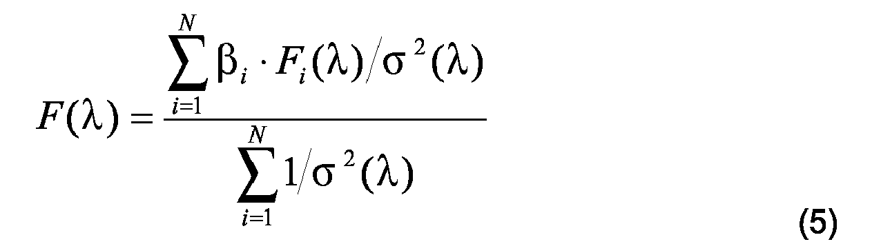
mit 
With
Alle anderen Punkte der Korrekturfunktion F(λ), das heißt in den Bereichen λ ≠ λi/i+1 ±ΔλLK, werden vorzugsweise nicht gemittelt, sondern einfach nach Gleichung 7 berechnet. (Dies ist gleichbedeutend mit einer Summierung nach Gleichung 5 über nur ein i.) Mit anderen Worten entspricht die Gesamtkorrekturfunktion F(λ) außerhalb der Verknüpfungsbereiche λi/i+1 ±ΔλLK, insbesondere für alle Wellenlängen außerhalb der Überschneidungspunkte λi/i+1, den Teilkorrekturfunktionen Fi(λ), gewichtet mit den für diese ermittelten Faktoren βi. Die so erhaltene Emissionskorrekturfunktion F(λ) ist in Figur 4 oben ebenfalls dargestellt. ![]()
Alle vorstehenden Schritte werden durch einen benutzerfreundlichen Computerprogrammalgorithmus, der vorzugsweise im Kit zusammen mit der Kalibriereinrichtung 10, den Farbstoffstandards 22 und den korrigierten und zertifizierten Fluoreszenzspektren li(λ) enthalten ist, automatisch durchgeführt.All other points of the correction function F (λ), that is to say in the ranges λ≠λ i / i + 1 ± Δλ LK , are preferably not averaged, but simply calculated according to Equation 7. (This is equivalent to a summation according to equation 5 over only one i.) In other words, the total correction function F (λ) outside the linking ranges corresponds to λ i / i + 1 ± Δλ LK , in particular for all wavelengths outside the overlap points λ i / i +1 , the partial correction functions F i (λ), weighted by the factors β i determined for them. The emission correction function F (λ) thus obtained is likewise shown in FIG. 4 above. ![]()
All the above steps are performed by a user-friendly computer program algorithm, preferably in the kit together with the
Spektren, die auf einem in dieser Weise kalibrierten Messsystem unter den gleichen Kalibriereinstellungen gemessenen werden, werden - nach Subtraktion entsprechender Blindwertspektren - durch einfache Multiplikation mit der Korrekturfunktion F(λ) spektral korrigiert. Man erhält auf diese Weise rückführbare, spektral korrigierte Lumineszenzspektren in relativen Intensitätseinheiten.Spectra measured on a measuring system calibrated in this way under the same calibration settings are spectrally corrected by subtraction of corresponding blank value spectra by simple multiplication with the correction function F (λ). In this way, traceable, spectrally corrected luminescence spectra are obtained in relative intensity units.
Das vorbeschriebene Beispiel bezieht sich auf die Erstellung einer Gesamtkorrekturfunktion für die Emission unter Verwendung von Emissionsstandards. Wird ein Satz von Anregungsstandards auf einem Lumineszenzmesssystem auf gleiche Weise gemessen und die erhaltenen Anregungsspektren mit einem Datensatz für die spektral korrigierten (zertifizierten) Anregungsspektren der Fluoreszenzstandards entsprechend verrechnet, so wird eine spektrale Anregungskorrekturfunktion erhalten.The example described above relates to the creation of an overall correction function for the emission using emission standards. If a set of excitation standards is measured in the same way on a luminescence measuring system and the excitation spectra obtained are correspondingly calculated with a data record for the spectrally corrected (certified) excitation spectra of the fluorescence standards, a spectral excitation correction function is obtained.
In abweichender Ausgestaltung der Erfindung sind die Kanäle 18 und die Reservoire 20 der Kalibriereinrichtung 10 gemäß Figur 1A bis 1 D mit Lösungen ein und desselben Fluoreszenzstandards in unterschiedlichen Konzentrationen gefüllt. Auch hierzu können etwa die vorgenannten Fluoreszenzstandards Verwendung finden. Eine solche Einrichtung eignet sich zur Bestimmung des Linearitätsbereichs des verwendeten Detektorsystems des Anregungs- und/oder Emissionskanals des Messsystems.In a different embodiment of the invention, the
- 1010
- Kalibriereinrichtungcalibration
- 1212
- Grundplattebaseplate
- 1414
- Unterseitebottom
- 1616
- Oberseitetop
- 1818
- Kanalchannel
- 2020
- Reservoirreservoir
- 2222
- Fluoreszenzstandardfluorescence standard
- 2424
- Fokussiereinrichtungfocusing
- 2626
- Fokussierflächefocusing surface
- ii
- fortlaufende Nr. eines Fluoreszenzstandards im Kit mit 1≤ i ≤ Nserial No. of a fluorescence standard in the kit with 1≤i≤N
- li(λ)l i (λ)
- spektral korrigiertes (zertifiziertes) Fluoreszenzspektrum des Fluoreszenzstandards ispectrally corrected (certified) fluorescence spectrum of the fluorescence standard i
- Ji(λ)J i (λ)
- gemessenes, blindwertkorrigiertes Fluoreszenzspektrummeasured, blind value corrected fluorescence spectrum
- Fi(λ)F i (λ)
- Teilkorrekturfunktion des Fluoreszenzstandards iPartial correction function of the fluorescence standard i
- F(λ)F (λ)
- GesamtkorrekturfunktionTotal correction function
- λi/i+1 λ i / i + 1
- Überschneidungswellenlängen aufeinander folgender Spektren des i-ten und (i+1)-ten StandardsIntersection wavelengths of successive spectra of the ith and (i + 1) th standards
- αα ii
- Verknüpfungsfaktor benachbarter TeilkorrekturfunktionenLink factor of adjacent partial correction functions
- βi β i
- Anschlussfaktorconnecting factor
Claims (24)
dadurch gekennzeichnet, dass
die zumindest eine Fokussierfläche (26) mit einem Innenraum des zumindest einen Kanals (18) fluchtet.Calibration device (10) according to claim 1,
characterized in that
the at least one focusing surface (26) is aligned with an interior of the at least one channel (18).
dadurch gekennzeichnet, dass
zumindest zwei in die Grundplatte (12) integrierte Fokussiereinrichtungen (18) vorgesehen sind, die insbesondere an einander gegenüberliegenden Randbereichen der Grundplatte (12) angeordnet sind.Calibration device (10) according to claim 1 or 2,
characterized in that
at least two in the base plate (12) integrated focusing devices (18) are provided, which are arranged in particular on opposite edge regions of the base plate (12).
dadurch gekennzeichnet, dass
die zumindest eine Fokussiereinrichtung (24) eine hochebene, reflektierende und/oder fluoreszierende Fokussierfläche (26) aufweist, die insbesondere eine Rauheit unterhalb der optischen Auflösung des zu kalibrierenden Lumineszenzmesssystems aufweist.Calibration device (10) according to one of the preceding claims,
characterized in that
the at least one focusing device (24) has a high-level, reflective and / or fluorescent focusing surface (26) which in particular has a roughness below the optical resolution of the luminescence measuring system to be calibrated.
dadurch gekennzeichnet, dass
die zumindest eine Fokussiereinrichtung (18) ein mit einer reflektierenden Metallschicht beschichtetes Substrat, insbesondere ein Chrom-besputterter Silizium-Wafer ist.Calibration device (10) according to claim 4,
characterized in that
the at least one focusing device (18) is a substrate coated with a reflective metal layer, in particular a chrome-sputtered silicon wafer.
dadurch gekennzeichnet, dass
die zumindest eine Fokussiereinrichtung (18) ein mit einem lumineszierenden Material beschichtetes Substrat, insbesondere ein mit einem fluoreszierenden Material, bevorzugt mit Quantumdots besputterter Wafer ist.Calibration device (10) according to claim 4,
characterized in that
the at least one focusing device (18) is a substrate coated with a luminescent material, in particular a wafer sputtered with a fluorescent material, preferably with quantum dots.
dadurch gekennzeichnet, dass
die Grundplatte (12) eine Mehrzahl von Kanälen (18) mit jeweils zumindest einem kommunizierenden Reservoir (20) aufweist.Calibration device (10) according to one of the preceding claims,
characterized in that
the base plate (12) has a plurality of channels (18) each having at least one communicating reservoir (20).
dadurch gekennzeichnet, dass
der zumindest eine Kanal (18) und/oder das mindestens eine diesem Kanal (18) zugeordnete Reservoir (20) mit zumindest einem Fluoreszenzstandard (22) zumindest teilweise befüllt ist.Calibration device (10) according to one of the preceding claims,
characterized in that
the at least one channel (18) and / or the at least one reservoir (20) associated with this channel (18) is at least partially filled with at least one fluorescence standard (22).
dadurch gekennzeichnet, dass
die Grundplatte (12) eine Mehrzahl von Kanälen (18) und diesen zugeordneten Reservoiren (20) aufweist, wobei die Kanäle (18) und/oder die zugeordneten Reservoire (20) mit unterschiedlichen Fluoreszenzstandards (22) zumindest teilweise befüllt sind, die derart gewählt sind, dass ihre spektral korrigierten Fluoreszenzspektren zusammen einen vorgegebenen Spektralbereich mit einer vorgegebenen Mindestintensität abdecken.Calibration device (10) according to one of claims 1 to 8,
characterized in that
the baseplate (12) has a plurality of channels (18) and associated reservoirs (20), the channels (18) and / or the associated reservoirs (20) being at least partially filled with different fluorescence standards (22) selected in such a way are that their spectrally corrected fluorescence spectra cover together a predetermined spectral range with a predetermined minimum intensity.
dadurch gekennzeichnet, dass
die vorgegebene Mindestintensität der Fluoreszenzbanden jeweils spektral aufeinander folgender, korrigierter Fluoreszenzspektren an ihren Überschneidungswellenlängen im UV/vis-Spektralbereich mit λ ≤ 700 nm mindestens 20 %, insbesondere mindestens 25 %, bevorzugt mindestens 30 %, der maximalen Intensität der flankierenden Banden beträgt.Calibration device (10) according to claim 9,
characterized in that
the predetermined minimum intensity of the fluorescence bands of spectrally successive, corrected fluorescence spectra at their overlap wavelengths in the UV / vis spectral range with λ ≦ 700 nm is at least 20%, in particular at least 25%, preferably at least 30%, of the maximum intensity of the flanking bands.
dadurch gekennzeichnet, dass
die vorgegebene Mindestintensität der Fluoreszenzbanden jeweils spektral aufeinander folgender, korrigierter Fluoreszenzspektren an ihren Überschneidungswellenlängen im NIR-Spektralbereich mit λ > 700 nm mindestens 10 %, insbesondere etwa 15 % der maximalen Bandenintensität beträgt.Calibration device (10) according to one of claims 9 or 10,
characterized in that
the predetermined minimum intensity of the fluorescence bands in each case spectrally successive, corrected fluorescence spectra at their overlap wavelengths in the NIR spectral range with λ> 700 nm is at least 10%, in particular approximately 15% of the maximum band intensity.
dadurch gekennzeichnet, dass
der vorgegebene Spektralbereich den UV/vis/NIR-Bereich zumindest teilweise abdeckt, insbesondere für eine Emissionskorrektur von 310 bis 730 nm reicht, bevorzugt von 300 bis 950 nm, oder für eine Anregungskorrektur von 280 bis 600 nm, bevorzugt von 240 bis 900 nm.Calibration device (10) according to one of claims 9 to 11,
characterized in that
the predetermined spectral range at least partially covers the UV / vis / NIR range, in particular for an emission correction from 310 to 730 nm, preferably from 300 to 950 nm, or for an excitation correction from 280 to 600 nm, preferably from 240 to 900 nm.
dadurch gekennzeichnet, dass
die Fluoreszenzstandards (22) Fluoreszenzbanden im UV/vis-Spektralbereich mit λ ≤ 700 nm mit einer Halbwertsbreite (FWHMi) zumindest von 1600 cm-1, insbesondere von zumindest 2000 cm-1, vorzugsweise von mindestens 2400 cm-1 aufweisen und im NIR-Bereich mit λ > 700 nm von mindestens 1200 cm-1 insbesondere mindestens 1400 cm-1.Calibration device (10) according to one of claims 9 to 12,
characterized in that
the fluorescence standards (22) have fluorescence bands in the UV / vis spectral range with λ ≦ 700 nm with a half-width (FWHM i ) of at least 1600 cm -1 , in particular of at least 2000 cm -1 , preferably of at least 2400 cm -1 and in the NIR Range with λ> 700 nm of at least 1200 cm -1, in particular at least 1400 cm -1 .
dadurch gekennzeichnet, dass
die Grundplatte (12) eine Mehrzahl von Kanälen (18) und diesen zugeordneten Reservoiren (20) aufweist, wobei die Kanäle (18) und/oder die zugeordneten Reservoire (20) mit Lösungen zumindest eines Fluoreszenzstandards (22) in unterschiedlichen Konzentrationen zumindest teilweise befüllt sind.Calibration device (10) according to one of claims 1 to 8,
characterized in that
the base plate (12) has a plurality of channels (18) and associated reservoirs (20), the channels (18) and / or the associated reservoirs (20) with solutions of at least one fluorescence standard (22) are at least partially filled in different concentrations.
dadurch gekennzeichnet, dass
der zumindest eine Fluoreszenzstandard (22) unstrukturierte Fluoreszenzbanden mit nur einem Maximum und einem stetigen Bandenverlauf aufweist.Calibration device (10) according to one of claims 9 to 14,
characterized in that
the at least one fluorescence standard (22) has unstructured fluorescence bands with only one maximum and one continuous band profile.
dadurch gekennzeichnet, dass
der zumindest eine Fluoreszenzstandard (22) einen spektralen Abstand zwischen seinem Absorptions- und Emissionsmaximum von mindestens 2000 cm-1, insbesondere von mindestens 2400 cm-1, vorzugsweise von mindestens 2800 cm-1, aufweist.Calibration device (10) according to one of claims 9 to 15,
characterized in that
the at least one fluorescence standard (22) has a spectral distance between its absorption and emission maximum of at least 2000 cm -1 , in particular of at least 2400 cm -1 , preferably of at least 2800 cm -1 .
dadurch gekennzeichnet, dass
der zumindest eine Fluoreszenzstandard (22) ein Emissionsstandard ist, ausgewählt aus der Gruppe enthaltend Biphenyl-, Naphthalin-, Cumarin-, Oxazin-, Merocyanin-, Hemicyanin- und Styryl-Derivate, insbesondere eine Kombination von diesen.Calibration device (10) according to one of claims 9 to 16,
characterized in that
the at least one fluorescence standard (22) is an emission standard selected from the group comprising biphenyl, naphthalene, coumarin, oxazine, merocyanine, hemicyanine and styryl derivatives, in particular a combination of these.
dadurch gekennzeichnet, dass
der zumindest eine Fluoreszenzstandard (22) ein Anregungsstandard ist, ausgewählt aus der Gruppe enthaltend Biphenyl-, Terphenyl-, Oxadiazol-, Cumarin-, Oxazin-, Merocyanin-, Hemicyanin- und Styryl-Derivate, insbesondere eine Kombination von diesen.Calibration device (10) according to one of claims 9 to 16,
characterized in that
the at least one fluorescence standard (22) is an excitation standard selected from the group comprising biphenyl, terphenyl, oxadiazole, coumarin, oxazine, merocyanine, hemicyanine and styryl derivatives, in particular a combination of these.
Priority Applications (2)
| Application Number | Priority Date | Filing Date | Title |
|---|---|---|---|
| EP10173098A EP2253688A3 (en) | 2005-03-18 | 2006-03-15 | Calibration device and dye kit and utilisation thereof for characterising luminescence measuring systems |
| EP10173097A EP2253687A3 (en) | 2005-03-18 | 2006-03-15 | Calibration device and dye kit and utilisation thereof for characterising luminescence measuring systems |
Applications Claiming Priority (2)
| Application Number | Priority Date | Filing Date | Title |
|---|---|---|---|
| DE102005013228 | 2005-03-18 | ||
| DE102005049365A DE102005049365A1 (en) | 2005-03-18 | 2005-10-11 | Calibration device and dye kit and their use for characterizing luminescence measuring systems |
Publications (2)
| Publication Number | Publication Date |
|---|---|
| EP1703271A1 true EP1703271A1 (en) | 2006-09-20 |
| EP1703271B1 EP1703271B1 (en) | 2010-08-18 |
Family
ID=36602537
Family Applications (3)
| Application Number | Title | Priority Date | Filing Date |
|---|---|---|---|
| EP06111148A Active EP1703271B1 (en) | 2005-03-18 | 2006-03-15 | Calibration device and dye kit and utilisation thereof for characterising luminescence measuring systems |
| EP10173097A Ceased EP2253687A3 (en) | 2005-03-18 | 2006-03-15 | Calibration device and dye kit and utilisation thereof for characterising luminescence measuring systems |
| EP10173098A Ceased EP2253688A3 (en) | 2005-03-18 | 2006-03-15 | Calibration device and dye kit and utilisation thereof for characterising luminescence measuring systems |
Family Applications After (2)
| Application Number | Title | Priority Date | Filing Date |
|---|---|---|---|
| EP10173097A Ceased EP2253687A3 (en) | 2005-03-18 | 2006-03-15 | Calibration device and dye kit and utilisation thereof for characterising luminescence measuring systems |
| EP10173098A Ceased EP2253688A3 (en) | 2005-03-18 | 2006-03-15 | Calibration device and dye kit and utilisation thereof for characterising luminescence measuring systems |
Country Status (4)
| Country | Link |
|---|---|
| US (1) | US8361394B2 (en) |
| EP (3) | EP1703271B1 (en) |
| AT (1) | ATE478330T1 (en) |
| DE (2) | DE102005049365A1 (en) |
Cited By (4)
| Publication number | Priority date | Publication date | Assignee | Title |
|---|---|---|---|---|
| WO2009127424A2 (en) * | 2008-04-17 | 2009-10-22 | Ese Gmbh | Fluorescence standard, and the use thereof |
| EP2905603A1 (en) * | 2014-02-11 | 2015-08-12 | Harun Parlar | Analytical Standard Composition |
| EP2233913B1 (en) * | 2009-03-24 | 2017-07-19 | BAM Bundesanstalt für Materialforschung und -prüfung | Optical standard for calibrating and characterising optical measuring devices |
| US10613031B2 (en) | 2015-12-18 | 2020-04-07 | Biofire Defense, Llc | Solid fluorescence standard |
Families Citing this family (18)
| Publication number | Priority date | Publication date | Assignee | Title |
|---|---|---|---|---|
| DE102004044717B8 (en) * | 2004-09-10 | 2010-12-16 | BAM Bundesanstalt für Materialforschung und -prüfung | Method and kit for calibrating a photoluminescence measuring system |
| DE102009041967A1 (en) * | 2009-09-17 | 2011-03-24 | Lre Medical Gmbh | Apparatus for analyzing body fluids, is provided with light source, and fluorescence standard with sensor unit for detecting portion of fluorescence standard emitted light |
| US9700889B2 (en) | 2009-11-23 | 2017-07-11 | Cyvek, Inc. | Methods and systems for manufacture of microarray assay systems, conducting microfluidic assays, and monitoring and scanning to obtain microfluidic assay results |
| US9500645B2 (en) | 2009-11-23 | 2016-11-22 | Cyvek, Inc. | Micro-tube particles for microfluidic assays and methods of manufacture |
| US9651568B2 (en) | 2009-11-23 | 2017-05-16 | Cyvek, Inc. | Methods and systems for epi-fluorescent monitoring and scanning for microfluidic assays |
| WO2011063408A1 (en) | 2009-11-23 | 2011-05-26 | Cyvek, Inc. | Method and apparatus for performing assays |
| US9759718B2 (en) | 2009-11-23 | 2017-09-12 | Cyvek, Inc. | PDMS membrane-confined nucleic acid and antibody/antigen-functionalized microlength tube capture elements, and systems employing them, and methods of their use |
| US10065403B2 (en) | 2009-11-23 | 2018-09-04 | Cyvek, Inc. | Microfluidic assay assemblies and methods of manufacture |
| US9855735B2 (en) | 2009-11-23 | 2018-01-02 | Cyvek, Inc. | Portable microfluidic assay devices and methods of manufacture and use |
| EP2689253B1 (en) | 2011-03-22 | 2021-03-10 | Cyvek, Inc. | Microfluidic devices and methods of manufacture |
| KR102070469B1 (en) * | 2012-03-08 | 2020-01-28 | 싸이벡, 아이엔씨 | Microfluidic assay assemblies and methods of manufacture |
| US10215995B2 (en) * | 2012-05-16 | 2019-02-26 | Cytonome/St, Llc | Large area, low f-number optical system |
| FR2994740B1 (en) * | 2012-08-21 | 2015-03-27 | Horiba Abx Sas | METHOD FOR COMPENSATING THE AGING OF A REAGENT DURING FLUORESCENCE MEASUREMENTS ON PARTICLES, AND BIOLOGICAL ANALYSIS DEVICE IMPLEMENTING THE METHOD |
| CN103217526B (en) * | 2013-04-08 | 2015-01-21 | 中国计量科学研究院 | Grating type luciferase label analysis meter testing standard plate and processing technology thereof |
| DE102013014401A1 (en) * | 2013-08-29 | 2015-03-05 | Giesecke & Devrient Gmbh | Calibration medium for value document sensors |
| GB201321609D0 (en) * | 2013-12-06 | 2014-01-22 | Starna Scient Ltd | PCR Validation Tubes |
| DE102013021097A1 (en) * | 2013-12-18 | 2015-06-18 | Euroimmun Medizinische Labordiagnostika Ag | Calibration standard for a device for imaging biological material |
| US10228367B2 (en) | 2015-12-01 | 2019-03-12 | ProteinSimple | Segmented multi-use automated assay cartridge |
Citations (8)
| Publication number | Priority date | Publication date | Assignee | Title |
|---|---|---|---|---|
| DE19847370A1 (en) * | 1998-10-14 | 2000-04-20 | Heinz Langhals | Use of perylene tetracarbobisimide dyes, tetraesters and tetracarboxylates are used as standard substances in fluorimetry and of bisanhydride as starting material |
| EP1213328A1 (en) * | 2000-12-08 | 2002-06-12 | Evotec OAI AG | Oxazine derivatives |
| US20020092973A1 (en) * | 1998-02-24 | 2002-07-18 | Caliper Technologies Corp. | Microfluidic devices and systems incorporating integrated optical elements |
| DE10200865A1 (en) * | 2001-03-28 | 2002-10-10 | Clondiag Chip Tech Gmbh | Device for referencing fluorescence signals |
| US20020154396A1 (en) * | 1998-03-20 | 2002-10-24 | Overbeck James W. | Wide field of view and high speed scanning microscopy |
| US6635487B1 (en) * | 2000-05-17 | 2003-10-21 | Caliper Technologies Corp. | Fluorescence standard for use in microfluidic instruments |
| WO2004065995A2 (en) * | 2003-01-23 | 2004-08-05 | Alpha Innotech Corporation | Identifying indicia and focusing target |
| DE10352123A1 (en) * | 2002-11-05 | 2004-08-19 | Evotec Oai Ag | Calibration unit, for measurement and assay, and analysis systems used in biotechnology, comprises two zones of recesses to hold identical or different calibration solutions |
Family Cites Families (13)
| Publication number | Priority date | Publication date | Assignee | Title |
|---|---|---|---|---|
| CA2198853A1 (en) * | 1994-09-02 | 1996-03-14 | Biometric Imaging, Inc. | Calibration method and apparatus for optical scanner |
| US5832165A (en) * | 1996-08-28 | 1998-11-03 | University Of Utah Research Foundation | Composite waveguide for solid phase binding assays |
| JP2000159543A (en) | 1998-09-22 | 2000-06-13 | Ohara Inc | Luminous fluorescent glass and glass ceramic |
| US20030030797A1 (en) | 1999-09-24 | 2003-02-13 | Henry Palladino | Solid state fluorescence and absorption spectroscopy |
| US6358387B1 (en) * | 2000-03-27 | 2002-03-19 | Caliper Technologies Corporation | Ultra high throughput microfluidic analytical systems and methods |
| DE10037850A1 (en) | 2000-08-01 | 2002-02-21 | Herbert P Jennissen | Process for the production of bioactive implant surfaces |
| US6479309B1 (en) | 2001-05-25 | 2002-11-12 | Advanced Micro Devices, Inc. | Method and apparatus for determining process layer conformality |
| WO2003021853A2 (en) * | 2001-09-05 | 2003-03-13 | Genicon Sciences Corporation | Apparatus for reading signals generated from resonance light scattered particle labels |
| JP2005504317A (en) | 2001-09-28 | 2005-02-10 | イビディ ゲムベーハー | Flow chamber |
| TWI314947B (en) * | 2002-04-24 | 2009-09-21 | Eastman Kodak Compan | Organic light emitting diode devices with improved operational stability |
| US7695688B2 (en) * | 2003-09-19 | 2010-04-13 | Applied Biosystems, Llc | High density plate filler |
| DE102004044717B8 (en) * | 2004-09-10 | 2010-12-16 | BAM Bundesanstalt für Materialforschung und -prüfung | Method and kit for calibrating a photoluminescence measuring system |
| US7951583B2 (en) * | 2006-03-10 | 2011-05-31 | Plc Diagnostics, Inc. | Optical scanning system |
-
2005
- 2005-10-11 DE DE102005049365A patent/DE102005049365A1/en not_active Withdrawn
-
2006
- 2006-03-15 EP EP06111148A patent/EP1703271B1/en active Active
- 2006-03-15 EP EP10173097A patent/EP2253687A3/en not_active Ceased
- 2006-03-15 AT AT06111148T patent/ATE478330T1/en active
- 2006-03-15 EP EP10173098A patent/EP2253688A3/en not_active Ceased
- 2006-03-15 DE DE502006007670T patent/DE502006007670D1/en active Active
- 2006-03-17 US US11/378,966 patent/US8361394B2/en active Active
Patent Citations (8)
| Publication number | Priority date | Publication date | Assignee | Title |
|---|---|---|---|---|
| US20020092973A1 (en) * | 1998-02-24 | 2002-07-18 | Caliper Technologies Corp. | Microfluidic devices and systems incorporating integrated optical elements |
| US20020154396A1 (en) * | 1998-03-20 | 2002-10-24 | Overbeck James W. | Wide field of view and high speed scanning microscopy |
| DE19847370A1 (en) * | 1998-10-14 | 2000-04-20 | Heinz Langhals | Use of perylene tetracarbobisimide dyes, tetraesters and tetracarboxylates are used as standard substances in fluorimetry and of bisanhydride as starting material |
| US6635487B1 (en) * | 2000-05-17 | 2003-10-21 | Caliper Technologies Corp. | Fluorescence standard for use in microfluidic instruments |
| EP1213328A1 (en) * | 2000-12-08 | 2002-06-12 | Evotec OAI AG | Oxazine derivatives |
| DE10200865A1 (en) * | 2001-03-28 | 2002-10-10 | Clondiag Chip Tech Gmbh | Device for referencing fluorescence signals |
| DE10352123A1 (en) * | 2002-11-05 | 2004-08-19 | Evotec Oai Ag | Calibration unit, for measurement and assay, and analysis systems used in biotechnology, comprises two zones of recesses to hold identical or different calibration solutions |
| WO2004065995A2 (en) * | 2003-01-23 | 2004-08-05 | Alpha Innotech Corporation | Identifying indicia and focusing target |
Cited By (7)
| Publication number | Priority date | Publication date | Assignee | Title |
|---|---|---|---|---|
| WO2009127424A2 (en) * | 2008-04-17 | 2009-10-22 | Ese Gmbh | Fluorescence standard, and the use thereof |
| WO2009127424A3 (en) * | 2008-04-17 | 2009-12-10 | Ese Gmbh | Fluorescence standard, and the use thereof |
| US8704158B2 (en) | 2008-04-17 | 2014-04-22 | Qiagen Lake Constance Gmbh | Fluorescence standard, and the use thereof |
| EP2233913B1 (en) * | 2009-03-24 | 2017-07-19 | BAM Bundesanstalt für Materialforschung und -prüfung | Optical standard for calibrating and characterising optical measuring devices |
| EP2905603A1 (en) * | 2014-02-11 | 2015-08-12 | Harun Parlar | Analytical Standard Composition |
| US10613031B2 (en) | 2015-12-18 | 2020-04-07 | Biofire Defense, Llc | Solid fluorescence standard |
| US11340169B2 (en) | 2015-12-18 | 2022-05-24 | Biofire Defense, Llc | Solid fluorescence standard |
Also Published As
| Publication number | Publication date |
|---|---|
| DE502006007670D1 (en) | 2010-09-30 |
| DE102005049365A1 (en) | 2006-09-21 |
| ATE478330T1 (en) | 2010-09-15 |
| EP2253688A3 (en) | 2011-04-06 |
| EP2253688A2 (en) | 2010-11-24 |
| EP2253687A2 (en) | 2010-11-24 |
| US20060233668A1 (en) | 2006-10-19 |
| EP1703271B1 (en) | 2010-08-18 |
| US8361394B2 (en) | 2013-01-29 |
| EP2253687A3 (en) | 2011-04-20 |
Similar Documents
| Publication | Publication Date | Title |
|---|---|---|
| EP1703271B1 (en) | Calibration device and dye kit and utilisation thereof for characterising luminescence measuring systems | |
| DE102005049364B4 (en) | Multifunctional calibration device and kit and their uses for characterizing luminescence measurement systems | |
| EP2068141B1 (en) | Kit, its use and method for calibration of a photoluminescence measuring system | |
| EP2233913B1 (en) | Optical standard for calibrating and characterising optical measuring devices | |
| US20080038835A1 (en) | Reference Member for Fluorescence Measurements, and Method for the Production Thereof | |
| Prenna et al. | Quantitation of DNA by cytofluorometry of the conventional Feulgen reaction | |
| EP1257809A1 (en) | Spr sensor and spr sensor arrangement | |
| EP3532841B1 (en) | Sample receiving element, analyses set and method for analyzing a liquid, in particular a cooling lubricant emulsion | |
| EP2145925B1 (en) | Use of a long-wave emitting cyanine compound as an NIR fluorescence standard and kit to calibrate photoluminescence measuring system | |
| EP0979402B1 (en) | Method for optical detection of analyte molecules in a natural biological medium | |
| DE602004008809T2 (en) | MULTIPLE MODE READER | |
| Neves et al. | Novel markers to early detect degradation on cellulose nitrate-based heritage at the submicrometer level using synchrotron UV–VIS multispectral luminescence | |
| DE3200391A1 (en) | OPTICAL DEVICE FOR A FLUORESCENT POLARIZATION DEVICE | |
| CN109030427B (en) | CCD spectrometer special for photoluminescence spectrum measurement | |
| Goldstein | Aspects of scanning microdensitometry: III. The monochromator system | |
| DE202015006402U1 (en) | Spectroscope, kit for its manufacture and combination of the spectroscope with a camera device | |
| EP3623796A1 (en) | Calibration standard for evanescence microscopy | |
| Royon | Towards quantitative fluorescence microscopy: A new solution for standardization, monitoring, and quality management | |
| Engel | i, United States Patent (10) Patent No.: US 7.544. 926 B2 | |
| EP3926022A1 (en) | Calibration target | |
| DE2328193C3 (en) | Device for splitting the light from a light source into at least two partial beams with a constant intensity ratio to one another | |
| DE102006009196A1 (en) | Luminescence signal referencing standard, has base material including volume doping with constituent part that is fluorescent and luminescent and includes rare earth metal and/or non-ferrous material e.g. cobalt, chrome or manganese | |
| DE102018117381A1 (en) | Transmission filter for calibrating a wavelength selecting selector | |
| DD249760A1 (en) | METHOD AND ARRANGEMENT FOR MEASURING THE PERFORMANCE OF LASER RADIATION | |
| Adar | I. DISCOVERY OF THE RAMAN EFFECT |
Legal Events
| Date | Code | Title | Description |
|---|---|---|---|
| PUAI | Public reference made under article 153(3) epc to a published international application that has entered the european phase |
Free format text: ORIGINAL CODE: 0009012 |
|
| AK | Designated contracting states |
Kind code of ref document: A1 Designated state(s): AT BE BG CH CY CZ DE DK EE ES FI FR GB GR HU IE IS IT LI LT LU LV MC NL PL PT RO SE SI SK TR |
|
| AX | Request for extension of the european patent |
Extension state: AL BA HR MK YU |
|
| 17P | Request for examination filed |
Effective date: 20070309 |
|
| 17Q | First examination report despatched |
Effective date: 20070402 |
|
| AKX | Designation fees paid |
Designated state(s): AT BE BG CH CY CZ DE DK EE ES FI FR GB GR HU IE IS IT LI LT LU LV MC NL PL PT RO SE SI SK TR |
|
| RAP1 | Party data changed (applicant data changed or rights of an application transferred) |
Owner name: SIGMA-ALDRICH GMBH Owner name: BAM BUNDESANSTALT FUER MATERIALFORSCHUNG UND- PRUE |
|
| GRAP | Despatch of communication of intention to grant a patent |
Free format text: ORIGINAL CODE: EPIDOSNIGR1 |
|
| GRAS | Grant fee paid |
Free format text: ORIGINAL CODE: EPIDOSNIGR3 |
|
| GRAA | (expected) grant |
Free format text: ORIGINAL CODE: 0009210 |
|
| RAP1 | Party data changed (applicant data changed or rights of an application transferred) |
Owner name: SIGMA-ALDRICH GMBH Owner name: BAM BUNDESANSTALT FUER MATERIALFORSCHUNG UND -PRUE |
|
| AK | Designated contracting states |
Kind code of ref document: B1 Designated state(s): AT BE BG CH CY CZ DE DK EE ES FI FR GB GR HU IE IS IT LI LT LU LV MC NL PL PT RO SE SI SK TR |
|
| REG | Reference to a national code |
Ref country code: GB Ref legal event code: FG4D Free format text: NOT ENGLISH |
|
| REG | Reference to a national code |
Ref country code: CH Ref legal event code: EP |
|
| REG | Reference to a national code |
Ref country code: IE Ref legal event code: FG4D Free format text: LANGUAGE OF EP DOCUMENT: GERMAN |
|
| REF | Corresponds to: |
Ref document number: 502006007670 Country of ref document: DE Date of ref document: 20100930 Kind code of ref document: P |
|
| REG | Reference to a national code |
Ref country code: NL Ref legal event code: VDEP Effective date: 20100818 |
|
| LTIE | Lt: invalidation of european patent or patent extension |
Effective date: 20100818 |
|
| PG25 | Lapsed in a contracting state [announced via postgrant information from national office to epo] |
Ref country code: FI Free format text: LAPSE BECAUSE OF FAILURE TO SUBMIT A TRANSLATION OF THE DESCRIPTION OR TO PAY THE FEE WITHIN THE PRESCRIBED TIME-LIMIT Effective date: 20100818 Ref country code: LT Free format text: LAPSE BECAUSE OF FAILURE TO SUBMIT A TRANSLATION OF THE DESCRIPTION OR TO PAY THE FEE WITHIN THE PRESCRIBED TIME-LIMIT Effective date: 20100818 |
|
| PG25 | Lapsed in a contracting state [announced via postgrant information from national office to epo] |
Ref country code: CY Free format text: LAPSE BECAUSE OF FAILURE TO SUBMIT A TRANSLATION OF THE DESCRIPTION OR TO PAY THE FEE WITHIN THE PRESCRIBED TIME-LIMIT Effective date: 20100818 Ref country code: BG Free format text: LAPSE BECAUSE OF FAILURE TO SUBMIT A TRANSLATION OF THE DESCRIPTION OR TO PAY THE FEE WITHIN THE PRESCRIBED TIME-LIMIT Effective date: 20101118 Ref country code: SI Free format text: LAPSE BECAUSE OF FAILURE TO SUBMIT A TRANSLATION OF THE DESCRIPTION OR TO PAY THE FEE WITHIN THE PRESCRIBED TIME-LIMIT Effective date: 20100818 Ref country code: PL Free format text: LAPSE BECAUSE OF FAILURE TO SUBMIT A TRANSLATION OF THE DESCRIPTION OR TO PAY THE FEE WITHIN THE PRESCRIBED TIME-LIMIT Effective date: 20100818 Ref country code: IS Free format text: LAPSE BECAUSE OF FAILURE TO SUBMIT A TRANSLATION OF THE DESCRIPTION OR TO PAY THE FEE WITHIN THE PRESCRIBED TIME-LIMIT Effective date: 20101218 Ref country code: PT Free format text: LAPSE BECAUSE OF FAILURE TO SUBMIT A TRANSLATION OF THE DESCRIPTION OR TO PAY THE FEE WITHIN THE PRESCRIBED TIME-LIMIT Effective date: 20101220 |
|
| REG | Reference to a national code |
Ref country code: IE Ref legal event code: FD4D |
|
| PG25 | Lapsed in a contracting state [announced via postgrant information from national office to epo] |
Ref country code: LV Free format text: LAPSE BECAUSE OF FAILURE TO SUBMIT A TRANSLATION OF THE DESCRIPTION OR TO PAY THE FEE WITHIN THE PRESCRIBED TIME-LIMIT Effective date: 20100818 Ref country code: SE Free format text: LAPSE BECAUSE OF FAILURE TO SUBMIT A TRANSLATION OF THE DESCRIPTION OR TO PAY THE FEE WITHIN THE PRESCRIBED TIME-LIMIT Effective date: 20100818 Ref country code: NL Free format text: LAPSE BECAUSE OF FAILURE TO SUBMIT A TRANSLATION OF THE DESCRIPTION OR TO PAY THE FEE WITHIN THE PRESCRIBED TIME-LIMIT Effective date: 20100818 Ref country code: GR Free format text: LAPSE BECAUSE OF FAILURE TO SUBMIT A TRANSLATION OF THE DESCRIPTION OR TO PAY THE FEE WITHIN THE PRESCRIBED TIME-LIMIT Effective date: 20101119 |
|
| PG25 | Lapsed in a contracting state [announced via postgrant information from national office to epo] |
Ref country code: DK Free format text: LAPSE BECAUSE OF FAILURE TO SUBMIT A TRANSLATION OF THE DESCRIPTION OR TO PAY THE FEE WITHIN THE PRESCRIBED TIME-LIMIT Effective date: 20100818 Ref country code: IE Free format text: LAPSE BECAUSE OF FAILURE TO SUBMIT A TRANSLATION OF THE DESCRIPTION OR TO PAY THE FEE WITHIN THE PRESCRIBED TIME-LIMIT Effective date: 20100818 |
|
| PG25 | Lapsed in a contracting state [announced via postgrant information from national office to epo] |
Ref country code: SK Free format text: LAPSE BECAUSE OF FAILURE TO SUBMIT A TRANSLATION OF THE DESCRIPTION OR TO PAY THE FEE WITHIN THE PRESCRIBED TIME-LIMIT Effective date: 20100818 Ref country code: CZ Free format text: LAPSE BECAUSE OF FAILURE TO SUBMIT A TRANSLATION OF THE DESCRIPTION OR TO PAY THE FEE WITHIN THE PRESCRIBED TIME-LIMIT Effective date: 20100818 Ref country code: IT Free format text: LAPSE BECAUSE OF FAILURE TO SUBMIT A TRANSLATION OF THE DESCRIPTION OR TO PAY THE FEE WITHIN THE PRESCRIBED TIME-LIMIT Effective date: 20100818 Ref country code: EE Free format text: LAPSE BECAUSE OF FAILURE TO SUBMIT A TRANSLATION OF THE DESCRIPTION OR TO PAY THE FEE WITHIN THE PRESCRIBED TIME-LIMIT Effective date: 20100818 Ref country code: RO Free format text: LAPSE BECAUSE OF FAILURE TO SUBMIT A TRANSLATION OF THE DESCRIPTION OR TO PAY THE FEE WITHIN THE PRESCRIBED TIME-LIMIT Effective date: 20100818 |
|
| PLBE | No opposition filed within time limit |
Free format text: ORIGINAL CODE: 0009261 |
|
| STAA | Information on the status of an ep patent application or granted ep patent |
Free format text: STATUS: NO OPPOSITION FILED WITHIN TIME LIMIT |
|
| PG25 | Lapsed in a contracting state [announced via postgrant information from national office to epo] |
Ref country code: ES Free format text: LAPSE BECAUSE OF FAILURE TO SUBMIT A TRANSLATION OF THE DESCRIPTION OR TO PAY THE FEE WITHIN THE PRESCRIBED TIME-LIMIT Effective date: 20101129 |
|
| 26N | No opposition filed |
Effective date: 20110519 |
|
| REG | Reference to a national code |
Ref country code: DE Ref legal event code: R097 Ref document number: 502006007670 Country of ref document: DE Effective date: 20110519 |
|
| BERE | Be: lapsed |
Owner name: BAM BUNDESANSTALT FUR MATERIALFORSCHUNG UND -PRUF Effective date: 20110331 Owner name: SIGMA-ALDRICH GMBH Effective date: 20110331 |
|
| PG25 | Lapsed in a contracting state [announced via postgrant information from national office to epo] |
Ref country code: MC Free format text: LAPSE BECAUSE OF NON-PAYMENT OF DUE FEES Effective date: 20110331 |
|
| REG | Reference to a national code |
Ref country code: CH Ref legal event code: PL |
|
| REG | Reference to a national code |
Ref country code: FR Ref legal event code: ST Effective date: 20111130 |
|
| PG25 | Lapsed in a contracting state [announced via postgrant information from national office to epo] |
Ref country code: BE Free format text: LAPSE BECAUSE OF NON-PAYMENT OF DUE FEES Effective date: 20110331 |
|
| PG25 | Lapsed in a contracting state [announced via postgrant information from national office to epo] |
Ref country code: FR Free format text: LAPSE BECAUSE OF NON-PAYMENT OF DUE FEES Effective date: 20110331 Ref country code: CH Free format text: LAPSE BECAUSE OF NON-PAYMENT OF DUE FEES Effective date: 20110331 Ref country code: LI Free format text: LAPSE BECAUSE OF NON-PAYMENT OF DUE FEES Effective date: 20110331 |
|
| REG | Reference to a national code |
Ref country code: DE Ref legal event code: R082 Ref document number: 502006007670 Country of ref document: DE Representative=s name: ZIMMERMANN & PARTNER, DE |
|
| REG | Reference to a national code |
Ref country code: DE Ref legal event code: R082 Ref document number: 502006007670 Country of ref document: DE Representative=s name: ZIMMERMANN & PARTNER PATENTANWAELTE MBB, DE Effective date: 20120302 Ref country code: DE Ref legal event code: R081 Ref document number: 502006007670 Country of ref document: DE Owner name: BAM BUNDESANSTALT FUER MATERIALFORSCHUNG UND -, DE Free format text: FORMER OWNER: BAM BUNDESANSTALT FUER MATERIALF, SIGMA-ALDRICH GMBH, , CH Effective date: 20120302 Ref country code: DE Ref legal event code: R082 Ref document number: 502006007670 Country of ref document: DE Representative=s name: ZIMMERMANN & PARTNER, DE Effective date: 20120302 Ref country code: DE Ref legal event code: R081 Ref document number: 502006007670 Country of ref document: DE Owner name: BAM BUNDESANSTALT FUER MATERIALFORSCHUNG UND -, DE Free format text: FORMER OWNERS: BAM BUNDESANSTALT FUER MATERIALFORSCHUNG UND -PRUEFUNG, 12205 BERLIN, DE; SIGMA-ALDRICH GMBH, BUCHS, CH Effective date: 20120302 |
|
| REG | Reference to a national code |
Ref country code: AT Ref legal event code: MM01 Ref document number: 478330 Country of ref document: AT Kind code of ref document: T Effective date: 20110315 |
|
| PG25 | Lapsed in a contracting state [announced via postgrant information from national office to epo] |
Ref country code: AT Free format text: LAPSE BECAUSE OF NON-PAYMENT OF DUE FEES Effective date: 20110315 |
|
| PG25 | Lapsed in a contracting state [announced via postgrant information from national office to epo] |
Ref country code: LU Free format text: LAPSE BECAUSE OF NON-PAYMENT OF DUE FEES Effective date: 20110315 |
|
| PG25 | Lapsed in a contracting state [announced via postgrant information from national office to epo] |
Ref country code: TR Free format text: LAPSE BECAUSE OF FAILURE TO SUBMIT A TRANSLATION OF THE DESCRIPTION OR TO PAY THE FEE WITHIN THE PRESCRIBED TIME-LIMIT Effective date: 20100818 |
|
| PG25 | Lapsed in a contracting state [announced via postgrant information from national office to epo] |
Ref country code: HU Free format text: LAPSE BECAUSE OF FAILURE TO SUBMIT A TRANSLATION OF THE DESCRIPTION OR TO PAY THE FEE WITHIN THE PRESCRIBED TIME-LIMIT Effective date: 20100818 |
|
| PGFP | Annual fee paid to national office [announced via postgrant information from national office to epo] |
Ref country code: GB Payment date: 20230321 Year of fee payment: 18 Ref country code: DE Payment date: 20230130 Year of fee payment: 18 |