EP1702575A2 - Radially expandable access system including trocar seal - Google Patents
Radially expandable access system including trocar seal Download PDFInfo
- Publication number
- EP1702575A2 EP1702575A2 EP06005056A EP06005056A EP1702575A2 EP 1702575 A2 EP1702575 A2 EP 1702575A2 EP 06005056 A EP06005056 A EP 06005056A EP 06005056 A EP06005056 A EP 06005056A EP 1702575 A2 EP1702575 A2 EP 1702575A2
- Authority
- EP
- European Patent Office
- Prior art keywords
- sleeve body
- distal end
- sleeve
- radially expandable
- radially
- Prior art date
- Legal status (The legal status is an assumption and is not a legal conclusion. Google has not performed a legal analysis and makes no representation as to the accuracy of the status listed.)
- Granted
Links
Images


Classifications
-
- A—HUMAN NECESSITIES
- A61—MEDICAL OR VETERINARY SCIENCE; HYGIENE
- A61B—DIAGNOSIS; SURGERY; IDENTIFICATION
- A61B17/00—Surgical instruments, devices or methods, e.g. tourniquets
- A61B17/34—Trocars; Puncturing needles
- A61B17/3417—Details of tips or shafts, e.g. grooves, expandable, bendable; Multiple coaxial sliding cannulas, e.g. for dilating
- A61B17/3421—Cannulas
- A61B17/3439—Cannulas with means for changing the inner diameter of the cannula, e.g. expandable
-
- A—HUMAN NECESSITIES
- A61—MEDICAL OR VETERINARY SCIENCE; HYGIENE
- A61B—DIAGNOSIS; SURGERY; IDENTIFICATION
- A61B17/00—Surgical instruments, devices or methods, e.g. tourniquets
- A61B17/00234—Surgical instruments, devices or methods, e.g. tourniquets for minimally invasive surgery
-
- A—HUMAN NECESSITIES
- A61—MEDICAL OR VETERINARY SCIENCE; HYGIENE
- A61B—DIAGNOSIS; SURGERY; IDENTIFICATION
- A61B17/00—Surgical instruments, devices or methods, e.g. tourniquets
- A61B17/34—Trocars; Puncturing needles
- A61B17/3417—Details of tips or shafts, e.g. grooves, expandable, bendable; Multiple coaxial sliding cannulas, e.g. for dilating
- A61B17/3421—Cannulas
- A61B17/3431—Cannulas being collapsible, e.g. made of thin flexible material
-
- A—HUMAN NECESSITIES
- A61—MEDICAL OR VETERINARY SCIENCE; HYGIENE
- A61B—DIAGNOSIS; SURGERY; IDENTIFICATION
- A61B17/00—Surgical instruments, devices or methods, e.g. tourniquets
- A61B17/34—Trocars; Puncturing needles
- A61B17/3474—Insufflating needles, e.g. Veress needles
-
- A—HUMAN NECESSITIES
- A61—MEDICAL OR VETERINARY SCIENCE; HYGIENE
- A61B—DIAGNOSIS; SURGERY; IDENTIFICATION
- A61B90/00—Instruments, implements or accessories specially adapted for surgery or diagnosis and not covered by any of the groups A61B1/00 - A61B50/00, e.g. for luxation treatment or for protecting wound edges
- A61B90/40—Apparatus fixed or close to patients specially adapted for providing an aseptic surgical environment
Definitions
- the present disclosure relates generally to apparatus and methods for providing access to an internal operative site during a surgical procedure and, more particularly, to access systems which may be percutaneously or otherwise introduced while in a narrow diameter configuration and which after introduction may be radially expanded to accommodate passage of larger diameter surgical instruments therethrough.
- Minimally invasive surgical procedures rely on obtaining percutaneous access to an internal surgical site using small-diameter access tubes (typically 5 to 12 mm), usually referred to as trocars, which penetrate through the skin and which open to the desired surgical site.
- a viewing scope is then introduced through one such trocar, and the surgeon operates using instruments introduced through other appropriately placed trocars while viewing the operative site on a video monitor connected to the viewing scope.
- the surgeon is thus able to perform a wide variety of surgical procedures requiring only several 5mm to 12 mm punctures at the surgical site. As a result, patient trauma and recovery time are typically reduced.
- laparoscopic procedures procedures in the abdominal area, which rely on a laparoscope for viewing, are typically referred to as laparoscopic procedures.
- the patient's abdominal region is typically insufflated (filled with pressured gas) to raise the abdominal wall and create sufficient operating space to perform a desired procedure.
- the trocars used in laparoscopic procedures must therefore include a valve at their proximal end to allow passage of the scope or surgical instruments while inhibiting leakage of the insufflating gas. It has also been proposed to perform laparoscopic procedures by mechanically expanding the abdomen rather than using insufflation.
- the radially expandable access systems disclosed therein may include a pneumoperitoneum needle, an expandable sleeve component which is percutaneously introduced while positioned over the pneumoperitoneum needle, a cannula having a pneumostasis valve permanently affixed at its proximal end, and an obturator which is removably inserted into the cannula to form an expansion member for the sleeve.
- the needle/sleeve assembly After the needle/sleeve assembly has been percutaneously introduced, and the peritoneal cavity insufflated in the case of laparoscopic procedures, the needle is removed from the sleeve, and the cannula/obturator assembly introduced through the sleeve.
- the sleeve which initially has a diameter in the range of 2-3 mm, is thus expanded to a final diameter depending on the cannula size, which can be selected from 5 mm, 10 mm, or 12 mm.
- Use of the radially expandable access system has many advantages, including reduced trauma to the patient and the ability to replace a cannula with a larger diameter cannula through a previously introduced sleeve.
- the present disclosure relates to access systems which may be percutaneously or otherwise introduced while in a narrow diameter configuration and, which after introduction, may be radially expanded to accommodate passage of larger diameter surgical instruments therethrough.
- a radially expandable sleeve component for use with an access system, is provided.
- the sleeve component includes a handle having a passage therethrough; and a sleeve body having a proximal end connected to the handle, a distal end, and an axial lumen aligned with the passage of the handle, the sleeve body having a length.
- the sleeve body is constructed from a radially expandable braid, wherein the braid is formed of a mesh of non-elastic filaments which axially shortens the length of the sleeve body as the sleeve body is radially expanded.
- the distal end of the sleeve body is flared radially outward.
- the radially expandable sleeve may further include a sheath substantially encasing the sleeve body.
- the length of the sleeve body is greater than a length of a cannula tube of an expansion assembly when the expansion assembly is operatively associated with the radially expandable sleeve component.
- the flared distal end of the sleeve body facilitates withdrawal of instruments from the radially expandable sleeve component.
- an access system includes a radially expandable sleeve component including a handle having a passage therethrough; and a sleeve body having a proximal end connected to the handle, a distal end, and an axial lumen aligned with the passage of the handle, the sleeve body having a length.
- the distal end of the sleeve body is flared radially outward.
- the access system further includes a cannula tube having a proximal end, a distal end, and a lumen extending therethrough.
- the cannula tube is sized for reception in the aperture of the handle of the radially expandable sleeve component.
- the cannula tube has a length which is shorter than the length of the sleeve body when the cannula tube is fully inserted into the sleeve body of the radially expandable sleeve component.
- the flared distal end of the sleeve body extends beyond the distal end of the cannula tube.
- the radially expandable sleeve further includes a sheath encasing the sleeve body along at least a portion of the length thereof.
- the sleeve body is constructed from a radially expandable braid.
- the braid is formed of a mesh of non-elastic filaments which axially shortens the length of the sleeve body as the sleeve body is radially expanded.
- the sheath maintains the flared distal end of sleeve body in a radially unexpanded condition. It is contemplated that the flared distal end of the sleeve body takes form upon removal of the sheath therefrom.
- an access system includes a radially expandable sleeve component including a handle having a passage therethrough; and a sleeve body having a proximal end connected to the handle, a distal end, and an axial lumen aligned with the passage of the handle, the sleeve body having a length.
- the distal end of the sleeve body tapers radially inward.
- the access system further includes a cannula tube having a proximal end, a distal end, and a lumen extending therethrough. The cannula tube is sized to be received in the aperture of the handle of the radially expandable sleeve component.
- the cannula tube has a length which is shorter than the length of the sleeve body when the cannula tube is fully inserted into the sleeve body of the radially expandable sleeve component so that the tapered distal end of the sleeve body engages an instrument inserted into the radially expandable sleeve component.
- the access system may further include an obturator removably receivable in the lumen of the cannula tube.
- the obturator has a tapered distal end which extends distally from the distal end of the cannula tube when the obturator is disposed in the lumen of the cannula tube.
- the access system may further include a pneumoperitoneum needle including a tubular needle; and an internal stylet removably receivable within the tubular needle.
- the flared distal end of the sleeve body extends beyond the distal end of the cannula tube.
- the radially expandable sleeve further includes a sheath encasing the sleeve body along at least a portion of the length thereof.
- the sheath desirably maintains the radially inward tapered distal end of the sleeve body in the radially tapered condition. In use, the radially inward tapered distal end of the sleeve body radially expands upon removal of the sheath therefrom.
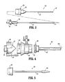
- FIG. 1 is a side view of a radially expandable sleeve component of the access system according to the present disclosure, including a removable sheath encasing a tubular braid portion thereof;
- FIG. 1A is a longitudinal cross-sectional view of the radially expandable sleeve component of FIG. 1;
- FIG. 2 is a side view of the radially expandable sleeve component of FIG. 1 with the sheath removed from the tubular braid portion thereof;
- FIG. 3 is a side view of a prior art pneumoperitoneum needle component for use with the radially expandable sleeve component of FIGS. 1 and 2;
- FIG. 4 is a side view of a prior art cannula assembly for use with the radially expandable sleeve component of FIGS. 1 and 2, shown with the cannula body, cannula hub, and valve cap removed or separated from each other, and further shown with the valve cap in partial section;
- FIG. 5 is a side view of a prior art obturator component for use with the radially expandable sleeve component of FIGS. 1 and 2, and cannula assembly of FIG. 3;
- FIG. 6 is a side view of the radially expandable sleeve component of FIGS. 1 and 2 having the cannula assembly of FIG. 3 operatively associated therewith and with the valve cap of the cannula assembly and the handle of the radially expandable sleeve component shown in partial section;
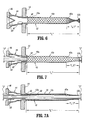
- FIG. 7 is a side view of the radially expandable sleeve component of FIGS. 1 and 2 having the cannula assembly of FIG. 3 operatively associated therewith and a surgical instrument extending therethrough, with the valve cap of the cannula assembly and the handle of the radially expandable sleeve component being shown in partial section;
- FIG. 7A is a cross-sectional side view of the radially expandable sleeve component of FIGS. 1 and 2 having the cannula assembly of FIG. 3 operatively associated therewith and a surgical instrument extending therethrough;
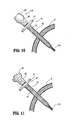
- FIGS. 8-13 illustrate use of the radially expandable sleeve component of FIGS. 1 and 2 in providing access to a patient's abdomen.
- the access system of the present disclosure is useful for forming and enlarging percutaneous penetrations into a variety of target locations within a patient's body for a multiplicity of purposes.
- Such purposes include drainage, intra-organ drug administration, feeding, perfusion, aspiration, and the like, most usually being the introduction of viewing scopes and surgical instruments for use in minimally invasive surgical procedures, such as laparoscopic procedures, thoracoscopic procedures, arthroscopic procedures, endoscopic procedures, and the like.
- the access system of the present disclosure will find use in hysteroscopic, colonoscopic, and other procedures where access is established through existing body orifices.
- the access systems of the present disclosure are particularly valuable in percutaneous procedures since they will create a very small initial penetration, usually being below about 5 mm, more usually being below about 4 mm, frequently being below about 3.5 mm, and preferably being 3 mm or below.
- the penetration will be subsequently enlarged to a desired final size, usually having a final diameter in the range from about 5 mm to 15 mm, more usually being from about 5 mm to 12 mm, and typically being from about 5 mm to 10 mm.
- the enlarged penetration will define an access lumen from the outside of the patient's body to the desired internal location, and it is a particular advantage of the present disclosure that the diameter of the access lumen may be changed as will be described in more detail hereinafter.
- the access system is valuable since it is capable of passing through the existing body orifice in its narrow-diameter configuration and be subsequently expanded with minimum discomfort and trauma to the patient.
- the access system of the present disclosure includes a number of individual components that may be assembled into different size configurations.
- the assembled components may also be disassembled after use, and the components selectively sterilized or replaced prior to reassembling the access system for fiuther use with a different patient.
- the different components and component assemblies and subassemblies will be described in greater detail below.
- Sterilization of the components of the trocar system disclosed herein may be accomplished by any suitable conventional sterilization technique, including heat, e.g., steam and autoclaving; chemical treatment, e.g., ethylene oxide exposure; radiation, and the like.
- heat e.g., steam and autoclaving
- chemical treatment e.g., ethylene oxide exposure
- radiation e.g., UV light
- reusable components will be washed to remove blood and other contaminating substances and then sterilized, preferably by exposure to steam.
- Disposable components will usually be radiation sterilized in their packages prior to distribution. Thus, disposable components will usually be ready to use out of the package.
- a radially expandable sleeve component or trocar seal for use as part of an access system, is generally designated as 10.
- distal refers to that portion of the tool, or component thereof which is further from the user while the term “proximal” refers to that portion of the tool or component thereof which is closer to the user.
- sleeve component 10 includes a sleeve body 12 defining a lumen 15 (see FIG. 1A) from a proximal end 12a to a distal end 12b thereof, and a handle 14 operatively connected to proximal end 12a of sleeve body 12.
- sleeve body 12 is constructed from a radially expandable braid, desirably inelastic, having an inner diameter of about 2 mm and an outer diameter of about 3.5 mm.
- Handle 14 includes a passage 16 (see FIG. 1A) formed therethrough, which passage 16 is substantially aligned with the lumen of sleeve body 12.
- a connector (not shown) is provided about passage 16 for selectively engaging a complementary connector provided on a cannula assembly 40.
- the complementary connectors may take the form of threads, bayonet fittings, and the like.
- passage of an expansion assembly therethrough causes radial expansion of sleeve body 12, typically to a final diameter of 5 mm, 10 mm, or 12 mm.
- Radially expandable sleeve 10 may be constructed in accordance with the details set forth in U.S. Pat. No. 5,431,676 , the full disclosure of which has been incorporated herein by reference.
- sleeve body 12 includes an intermediate portion 12c having a uniform diameter along substantially the entire length thereof, and a distal end 12b having a diameter which is larger than the diameter of intermediate portion 12c.
- a sheath 18 encases and/or otherwise covers sleeve body 12.
- Sheath 18 extends the entire length of sleeve body 12.
- sheath 18 is fabricated from a plastic or elastomeric material, e.g., polyurethane, tetrafluorethylene, fluorinated ethylene-propylene, or the like.
- sheath 18 will be weakened along an axial line (as by a pair of thin or weakened axial grooves or lines (not shown)) to facilitate splitting of sheath 18 at some point during the procedure.
- the axial grooves enable sheath 18 to be divided or split along the length thereof, as cannula assembly 40 is received in the lumen of sleeve body 12, and thus allow sleeve body 12 to radially expand.
- sheath 18 helps to maintain flared distal end 12b closed (i.e., in a radially unexpanded condition) prior to introduction of the first surgical instrument.
- sheath 18 constricts distal end 12b such that distal end 12b has a diameter which is substantially equal to the diameter of intermediate portion 12c of sleeve body 12.
- the braid of sleeve body 12 is preferably formed as a mesh of individual non-elastic filaments (e.g., composed of polyamide fiber, stainless steel, or the like) so that radial expansion causes axial shortening of the braid.
- the braid of sleeve body 12 may be constructed from round filaments, flat or ribbon filaments, square filaments, or the like. Non-round filaments may advantageously reduce the axial force required to provide radial expansion.
- the filament width or diameter will typically be from about 0.002 inches to about 0.25 inches, usually being from about 0.005 inches to about 0.010 inches.
- Pneumoperitoneum needle assembly 20 includes a tubular needle body 22, and a stylet 24 for operative engagement with tubular needle body 22.
- Tubular needle body 22 includes a hub 25, having a male bayonet connector 26 extending therefrom, provided at a proximal end thereof.
- Stylet 24 is spring-loaded in a connector 28 which is provided at a proximal end thereof.
- Connector 28 includes a male bayonet fitting 30 which is receivably mounted in a female bayonet fitting (not illustrated) provided in hub 25 of needle body 22.
- Stylet 24 further includes an insufflation valve 32 provided at a proximal end thereof, and a port 34 formed in a distal end thereof Accordingly, insufflation gas, introduced through valve 32, is permitted to be released through port 34.
- stylet 24 is to be mounted within tubular needle body 22 by way of bayonet fittings 30 of connector 28. The distal end of stylet 24 will extend from distal end 36 of needle body 22, and stylet 24 will retract into needle body 22 when needle body 22 is engaged against tissue, as described in more detail below.
- Cannula assembly 40 for use as part of an access system, is generally designated as 40.
- Cannula assembly 40 includes a cannula tube 42, a cannula hub 44 connectable to cannula tube 42, and a valve cap 46 removably connectable to cannula hub 44.
- Cannula tube 42 includes a threaded connector 48 at a proximal end thereof which may be removably secured or connected to a fitting 50 provided at a distal end of cannula hub 44.
- Valve cap 46 desirably includes a pneumostasis valve element 52 and is configured to mate with a male bayonet fitting 54 provided at a proximal end of cannula hub 44.
- a second disk valve element 56 may be mounted in tandem with the pneumostasis valve element 52 to engage against an outer surface of a surgical instrument (not shown) when the surgical instrument is introduced through cannula assembly 40.
- Valve element 56 is generally sized for a relatively large instrument, e.g., an instrument having a diameter of about 12 mm.
- a reducing element 58 may be provided for reducing the size of the port of valve element 56 to accommodate relatively smaller instruments, e.g., instruments having a diameter of about 10 mm.
- Obturator 60 for use as part of an access system, is generally designated as 60.
- Obturator 60 generally includes a shaft 62, a tapered distal end 64, and a handle 66.
- Obturator 60 is intended to be placed within a central lumen of cannula assembly 40 in order to form an expansion assembly for use as described below.
- radially expandable sleeve component 10 is shown in operative association with cannula assembly 40.
- cannula tube 42 of cannula assembly 40 has been fully inserted into the lumen of sleeve body 12 of expandable sleeve component 10.
- sleeve body 12 has a length "L" which is greater then the length of cannula tube 42 when cannula tube 42 has been fully inserted into expandable sleeve component 10.
- distal end 12b of sleeve body 12 extends distally beyond a distal edge 42a of cannula tube 42.
- length "L” of sleeve body 12 is such that flared distal end 12b thereof is spaced an axial distance "L1" from distal edge 42a of cannula tube 42 when cannula tube 42 is fully inserted into expandable sleeve component 10.
- flared distal end 12b of sleeve body 12 effectively forms and/or acts as an instrument seal against the surface of an instrument "I” introduced into and extending through cannula tube 42 of cannula assembly 40 and sleeve body 12 of expandable sleeve component 10.
- Flared distal end 12b of sleeve body 12 is provided in order to facilitate removal of instrument "I” from cannula assembly 40 and, in particular, from sleeve body 12 of expandable sleeve component 10.
- distal end 12b of sleeve body 12 is preferably provided with a flare, it is within the scope of the present disclosure, that distal end 12b of sleeve body 12 does not have to include a flare or the like in order to create and/or act as a instrument seal.
- pneumostasis valve element 52 of cannula hub 44 may take the form of a duck bill or "zero" valve.
- Valve element 52 may include two planar tapering portions which intersect at their distal ends to define an abutment face.
- the planar tapering portions may each include one or more inwardly directed, longitudinally oriented ribs to facilitate passage of instrument "I".
- the abutment face permits passage of instrument "I” through valve element 52, but in the absence of instrument "I", and particularly when cannula assembly 40 is inserted into an insufflated body cavity, the abutment face forms a gas-tight seal that isolates the insufflation cavity from the ambient surroundings.
- Valve element 52 also includes at least one, preferably two, reinforcing ribs (not shown) to stabilize valve element 52.
- the ribs are positioned to engage instrument “I” to guide instrument “I” through the slit of valve element 52 and prevent piercing of valve element 52 by the tip of instrument "I".
- U.S Patent 5,603,702 the entire content of which is incorporated herein by reference, for a more detailed discussion of a valve element.
- a radially expandable sleeve component 10 having a pneumoperitoneum needle 20 inserted therein is introduced through a patient's abdomen "A" (or other body location) by engaging sharpened distal end 36 of needle 20 against the tissue and advancing the assembly (e.g., expandable sleeve component 10 operatively coupled with needle 20) until sleeve body 12 of radially expandable sleeve component 10 extends across the tissue.
- the assembly e.g., expandable sleeve component 10 operatively coupled with needle 20
- needle 20 is removed from expandable sleeve component 10 and an expansion assembly 110, including cannula assembly 40 having obturator 60 operatively associated therewith, is introduced through radially expandable sleeve component 10.
- Introduction of expansion assembly 110 into radially expandable sleeve component 10 results in radial expansion of sleeve body 12 (see FIG. 10). In so doing, sheath 18 is divided or split along the length of the axial grooves (not shown).
- expansion sleeve 110 into expandable sleeve component 10 to radially expand sleeve body 12 results in axial shortening of sleeve body 12 to thereby help anchor expansion assembly 110 in place and to help seal the exterior of expansion assembly 110 against the tissue.
- sleeve body 12 has a length "L" sufficient that when expansion assembly 110 is fully inserted into sleeve body 12 of expandable sleeve component 10, obturator 60 and cannula tube 40 do not radially expand distal end 12b of sleeve body 12 and, thus, do not split open a distal end of sheath 18.
- obturator 60 may then be removed from cannula assembly 40 and radially expandable sleeve 40, leaving an access channel through abdominal wall "A".
- a surgical instrument "I” e.g., surgical graspers, staplers, tackers, fastener appliers, etc.
- instrument "I” has a length such that an end effector of instrument “I” is extendable beyond distal edge 42a of cannula tube 42 and beyond distal end 12b of sleeve body 12 of expandable sleeve component 10.
- distal end 12b of sleeve body 12 acts as an instrument seal against the outer surface of instrument "I", thereby reducing the escape or passage of insufflation fluid through cannula tube 42.
- Such a fluid-tight seal is a particular advantage in laparoscopic procedures.
- surgical instrument “I” may be removed and/or withdrawn from expansion assembly 110 and radially expandable sleeve component 10.
- Flared distal end 12b of sleeve body 12 facilitates the removal and/or withdrawal of surgical instrument “I” from expansion assembly 110 and radially expandable sleeve component 10.
- flared distal end 12b of sleeve body 12 may act like a funnel to facilitate removal and/or retraction of a tissue or organ specimen from the abdominal cavity.
Abstract
Description
- The present disclosure relates generally to apparatus and methods for providing access to an internal operative site during a surgical procedure and, more particularly, to access systems which may be percutaneously or otherwise introduced while in a narrow diameter configuration and which after introduction may be radially expanded to accommodate passage of larger diameter surgical instruments therethrough.
- Minimally invasive surgical procedures rely on obtaining percutaneous access to an internal surgical site using small-diameter access tubes (typically 5 to 12 mm), usually referred to as trocars, which penetrate through the skin and which open to the desired surgical site. A viewing scope is then introduced through one such trocar, and the surgeon operates using instruments introduced through other appropriately placed trocars while viewing the operative site on a video monitor connected to the viewing scope. The surgeon is thus able to perform a wide variety of surgical procedures requiring only several 5mm to 12 mm punctures at the surgical site. As a result, patient trauma and recovery time are typically reduced.
- Particular minimally invasive surgical procedures are often referred to based on the type of scope used to view the region of the body which is the operative site. For example, procedures in the abdominal area, which rely on a laparoscope for viewing, are typically referred to as laparoscopic procedures. In such laparoscopic procedures, the patient's abdominal region is typically insufflated (filled with pressured gas) to raise the abdominal wall and create sufficient operating space to perform a desired procedure. The trocars used in laparoscopic procedures must therefore include a valve at their proximal end to allow passage of the scope or surgical instruments while inhibiting leakage of the insufflating gas. It has also been proposed to perform laparoscopic procedures by mechanically expanding the abdomen rather than using insufflation.
- Recently, a radially expandable access system has been developed, as shown and described in
U.S. Pat. Nos. 5,183,464 ;5,431,676 ;5,814,058 ;5,827,319 ;6,080,174 ;6,245,052 ;6,325,812 ;6,494,893 ; and6,589,225 , as well as inU.S. Pat. Appl. Nos. 2001/0039430 ;2002/0002360 ;2003/0023259 ; and2003/0199809 , the entire contents of each of which are incorporated herein by reference. The radially expandable access systems disclosed therein may include a pneumoperitoneum needle, an expandable sleeve component which is percutaneously introduced while positioned over the pneumoperitoneum needle, a cannula having a pneumostasis valve permanently affixed at its proximal end, and an obturator which is removably inserted into the cannula to form an expansion member for the sleeve. After the needle/sleeve assembly has been percutaneously introduced, and the peritoneal cavity insufflated in the case of laparoscopic procedures, the needle is removed from the sleeve, and the cannula/obturator assembly introduced through the sleeve. The sleeve, which initially has a diameter in the range of 2-3 mm, is thus expanded to a final diameter depending on the cannula size, which can be selected from 5 mm, 10 mm, or 12 mm. Use of the radially expandable access system has many advantages, including reduced trauma to the patient and the ability to replace a cannula with a larger diameter cannula through a previously introduced sleeve. - While the radially expandable access system represents a substantial advance over conventional trocars, the need and desire exists for improved radially expandable access systems, component kits for such systems, and methods for reconstructing and reusing such systems.
- The present disclosure relates to access systems which may be percutaneously or otherwise introduced while in a narrow diameter configuration and, which after introduction, may be radially expanded to accommodate passage of larger diameter surgical instruments therethrough.
- According to an aspect of the present disclosure, a radially expandable sleeve component, for use with an access system, is provided. The sleeve component includes a handle having a passage therethrough; and a sleeve body having a proximal end connected to the handle, a distal end, and an axial lumen aligned with the passage of the handle, the sleeve body having a length. The sleeve body is constructed from a radially expandable braid, wherein the braid is formed of a mesh of non-elastic filaments which axially shortens the length of the sleeve body as the sleeve body is radially expanded. The distal end of the sleeve body is flared radially outward.
- The radially expandable sleeve may further include a sheath substantially encasing the sleeve body. Desirably, the length of the sleeve body is greater than a length of a cannula tube of an expansion assembly when the expansion assembly is operatively associated with the radially expandable sleeve component.
- It is contemplated that the flared distal end of the sleeve body facilitates withdrawal of instruments from the radially expandable sleeve component.
- According to another aspect of the present disclosure, an access system is provided. The access system includes a radially expandable sleeve component including a handle having a passage therethrough; and a sleeve body having a proximal end connected to the handle, a distal end, and an axial lumen aligned with the passage of the handle, the sleeve body having a length. The distal end of the sleeve body is flared radially outward. The access system further includes a cannula tube having a proximal end, a distal end, and a lumen extending therethrough. The cannula tube is sized for reception in the aperture of the handle of the radially expandable sleeve component. The cannula tube has a length which is shorter than the length of the sleeve body when the cannula tube is fully inserted into the sleeve body of the radially expandable sleeve component.
- Desirably, when the cannula tube is fully inserted into the sleeve body of the radially expandable sleeve component the flared distal end of the sleeve body extends beyond the distal end of the cannula tube. The radially expandable sleeve further includes a sheath encasing the sleeve body along at least a portion of the length thereof.
- In an embodiment, the sleeve body is constructed from a radially expandable braid. The braid is formed of a mesh of non-elastic filaments which axially shortens the length of the sleeve body as the sleeve body is radially expanded.
- Desirably, the sheath maintains the flared distal end of sleeve body in a radially unexpanded condition. It is contemplated that the flared distal end of the sleeve body takes form upon removal of the sheath therefrom.
- According to yet another aspect of the present disclosure, an access system is provided. The access system includes a radially expandable sleeve component including a handle having a passage therethrough; and a sleeve body having a proximal end connected to the handle, a distal end, and an axial lumen aligned with the passage of the handle, the sleeve body having a length. The distal end of the sleeve body tapers radially inward. The access system further includes a cannula tube having a proximal end, a distal end, and a lumen extending therethrough. The cannula tube is sized to be received in the aperture of the handle of the radially expandable sleeve component. The cannula tube has a length which is shorter than the length of the sleeve body when the cannula tube is fully inserted into the sleeve body of the radially expandable sleeve component so that the tapered distal end of the sleeve body engages an instrument inserted into the radially expandable sleeve component.
- The access system may further include an obturator removably receivable in the lumen of the cannula tube. The obturator has a tapered distal end which extends distally from the distal end of the cannula tube when the obturator is disposed in the lumen of the cannula tube. The access system may further include a pneumoperitoneum needle including a tubular needle; and an internal stylet removably receivable within the tubular needle.
- Desirably, when the cannula tube is fully inserted into the sleeve body of the radially expandable sleeve component the flared distal end of the sleeve body extends beyond the distal end of the cannula tube.
- The radially expandable sleeve further includes a sheath encasing the sleeve body along at least a portion of the length thereof. The sheath desirably maintains the radially inward tapered distal end of the sleeve body in the radially tapered condition. In use, the radially inward tapered distal end of the sleeve body radially expands upon removal of the sheath therefrom.
- Other objects and features of the present disclosure will become apparent from consideration of the following description taken in conjunction with the accompanying drawings.
- By way of example only, embodiments of the radially expandable access system of the present disclosure, will be described with reference to the accompanying drawings, in which:
- FIG. 1 is a side view of a radially expandable sleeve component of the access system according to the present disclosure, including a removable sheath encasing a tubular braid portion thereof;
- FIG. 1A is a longitudinal cross-sectional view of the radially expandable sleeve component of FIG. 1;
- FIG. 2 is a side view of the radially expandable sleeve component of FIG. 1 with the sheath removed from the tubular braid portion thereof;
- FIG. 3 is a side view of a prior art pneumoperitoneum needle component for use with the radially expandable sleeve component of FIGS. 1 and 2;
- FIG. 4 is a side view of a prior art cannula assembly for use with the radially expandable sleeve component of FIGS. 1 and 2, shown with the cannula body, cannula hub, and valve cap removed or separated from each other, and further shown with the valve cap in partial section;
- FIG. 5 is a side view of a prior art obturator component for use with the radially expandable sleeve component of FIGS. 1 and 2, and cannula assembly of FIG. 3;
- FIG. 6 is a side view of the radially expandable sleeve component of FIGS. 1 and 2 having the cannula assembly of FIG. 3 operatively associated therewith and with the valve cap of the cannula assembly and the handle of the radially expandable sleeve component shown in partial section;
- FIG. 7 is a side view of the radially expandable sleeve component of FIGS. 1 and 2 having the cannula assembly of FIG. 3 operatively associated therewith and a surgical instrument extending therethrough, with the valve cap of the cannula assembly and the handle of the radially expandable sleeve component being shown in partial section;
- FIG. 7A is a cross-sectional side view of the radially expandable sleeve component of FIGS. 1 and 2 having the cannula assembly of FIG. 3 operatively associated therewith and a surgical instrument extending therethrough; and
- FIGS. 8-13 illustrate use of the radially expandable sleeve component of FIGS. 1 and 2 in providing access to a patient's abdomen.
- The access system of the present disclosure is useful for forming and enlarging percutaneous penetrations into a variety of target locations within a patient's body for a multiplicity of purposes. Such purposes include drainage, intra-organ drug administration, feeding, perfusion, aspiration, and the like, most usually being the introduction of viewing scopes and surgical instruments for use in minimally invasive surgical procedures, such as laparoscopic procedures, thoracoscopic procedures, arthroscopic procedures, endoscopic procedures, and the like. In addition to percutaneous procedures, the access system of the present disclosure will find use in hysteroscopic, colonoscopic, and other procedures where access is established through existing body orifices.
- The access systems of the present disclosure are particularly valuable in percutaneous procedures since they will create a very small initial penetration, usually being below about 5 mm, more usually being below about 4 mm, frequently being below about 3.5 mm, and preferably being 3 mm or below. The penetration will be subsequently enlarged to a desired final size, usually having a final diameter in the range from about 5 mm to 15 mm, more usually being from about 5 mm to 12 mm, and typically being from about 5 mm to 10 mm. The enlarged penetration will define an access lumen from the outside of the patient's body to the desired internal location, and it is a particular advantage of the present disclosure that the diameter of the access lumen may be changed as will be described in more detail hereinafter. In non-percutaneous procedures, the access system is valuable since it is capable of passing through the existing body orifice in its narrow-diameter configuration and be subsequently expanded with minimum discomfort and trauma to the patient.
- The access system of the present disclosure includes a number of individual components that may be assembled into different size configurations. The assembled components may also be disassembled after use, and the components selectively sterilized or replaced prior to reassembling the access system for fiuther use with a different patient. The different components and component assemblies and subassemblies will be described in greater detail below.
- Sterilization of the components of the trocar system disclosed herein may be accomplished by any suitable conventional sterilization technique, including heat, e.g., steam and autoclaving; chemical treatment, e.g., ethylene oxide exposure; radiation, and the like. After use, reusable components will be washed to remove blood and other contaminating substances and then sterilized, preferably by exposure to steam. Disposable components will usually be radiation sterilized in their packages prior to distribution. Thus, disposable components will usually be ready to use out of the package.
- Referring initially to FIGS. 1, 1A and 2, wherein like reference numerals identify similar or identical structural elements, a radially expandable sleeve component or trocar seal, according to an embodiment of the present disclosure, for use as part of an access system, is generally designated as 10. As used herein, the term "distal" refers to that portion of the tool, or component thereof which is further from the user while the term "proximal" refers to that portion of the tool or component thereof which is closer to the user.
- As seen in FIGS. 1,1A and 2,
sleeve component 10 includes asleeve body 12 defining a lumen 15 (see FIG. 1A) from aproximal end 12a to adistal end 12b thereof, and ahandle 14 operatively connected toproximal end 12a ofsleeve body 12. Preferably,sleeve body 12 is constructed from a radially expandable braid, desirably inelastic, having an inner diameter of about 2 mm and an outer diameter of about 3.5 mm.Handle 14 includes a passage 16 (see FIG. 1A) formed therethrough, whichpassage 16 is substantially aligned with the lumen ofsleeve body 12. Desirably and typically a connector (not shown) is provided aboutpassage 16 for selectively engaging a complementary connector provided on acannula assembly 40. For example, the complementary connectors may take the form of threads, bayonet fittings, and the like. As will be described in greater detail below, passage of an expansion assembly therethrough causes radial expansion ofsleeve body 12, typically to a final diameter of 5 mm, 10 mm, or 12 mm. Radiallyexpandable sleeve 10 may be constructed in accordance with the details set forth inU.S. Pat. No. 5,431,676 , the full disclosure of which has been incorporated herein by reference. - As seen in FIG. 2,
distal end 12b ofsleeve body 12 is flared radially outward. In particular,sleeve body 12 includes anintermediate portion 12c having a uniform diameter along substantially the entire length thereof, and adistal end 12b having a diameter which is larger than the diameter ofintermediate portion 12c. - As seen in FIG. 1, a
sheath 18 encases and/or otherwise coverssleeve body 12.Sheath 18 extends the entire length ofsleeve body 12. Desirably,sheath 18 is fabricated from a plastic or elastomeric material, e.g., polyurethane, tetrafluorethylene, fluorinated ethylene-propylene, or the like. Desirably,sheath 18 will be weakened along an axial line (as by a pair of thin or weakened axial grooves or lines (not shown)) to facilitate splitting ofsheath 18 at some point during the procedure. As described in more detail hereinafter, the axial grooves enablesheath 18 to be divided or split along the length thereof, ascannula assembly 40 is received in the lumen ofsleeve body 12, and thus allowsleeve body 12 to radially expand. - Additionally, as seen in FIG. 1,
sheath 18 helps to maintain flareddistal end 12b closed (i.e., in a radially unexpanded condition) prior to introduction of the first surgical instrument. In other words,sheath 18 constrictsdistal end 12b such thatdistal end 12b has a diameter which is substantially equal to the diameter ofintermediate portion 12c ofsleeve body 12. - By way of example only, the braid of
sleeve body 12 is preferably formed as a mesh of individual non-elastic filaments (e.g., composed of polyamide fiber, stainless steel, or the like) so that radial expansion causes axial shortening of the braid. Additionally, the braid ofsleeve body 12 may be constructed from round filaments, flat or ribbon filaments, square filaments, or the like. Non-round filaments may advantageously reduce the axial force required to provide radial expansion. The filament width or diameter will typically be from about 0.002 inches to about 0.25 inches, usually being from about 0.005 inches to about 0.010 inches. - Turning now to FIG. 3, a pneumoperitoneum needle assembly, for use as part of an access system, is generally designated as 20.
Pneumoperitoneum needle assembly 20 includes atubular needle body 22, and astylet 24 for operative engagement withtubular needle body 22.Tubular needle body 22 includes ahub 25, having amale bayonet connector 26 extending therefrom, provided at a proximal end thereof.Stylet 24 is spring-loaded in aconnector 28 which is provided at a proximal end thereof.Connector 28 includes a male bayonet fitting 30 which is receivably mounted in a female bayonet fitting (not illustrated) provided inhub 25 ofneedle body 22.Stylet 24 further includes aninsufflation valve 32 provided at a proximal end thereof, and aport 34 formed in a distal end thereof Accordingly, insufflation gas, introduced throughvalve 32, is permitted to be released throughport 34. In use,stylet 24 is to be mounted withintubular needle body 22 by way ofbayonet fittings 30 ofconnector 28. The distal end ofstylet 24 will extend fromdistal end 36 ofneedle body 22, andstylet 24 will retract intoneedle body 22 whenneedle body 22 is engaged against tissue, as described in more detail below. - Turning now to FIG. 4, a cannula assembly, for use as part of an access system, is generally designated as 40.
Cannula assembly 40 includes acannula tube 42, acannula hub 44 connectable tocannula tube 42, and avalve cap 46 removably connectable tocannula hub 44.Cannula tube 42 includes a threadedconnector 48 at a proximal end thereof which may be removably secured or connected to a fitting 50 provided at a distal end ofcannula hub 44.Valve cap 46 desirably includes apneumostasis valve element 52 and is configured to mate with a male bayonet fitting 54 provided at a proximal end ofcannula hub 44. A seconddisk valve element 56 may be mounted in tandem with thepneumostasis valve element 52 to engage against an outer surface of a surgical instrument (not shown) when the surgical instrument is introduced throughcannula assembly 40.Valve element 56 is generally sized for a relatively large instrument, e.g., an instrument having a diameter of about 12 mm. A reducingelement 58 may be provided for reducing the size of the port ofvalve element 56 to accommodate relatively smaller instruments, e.g., instruments having a diameter of about 10 mm. - Turning now to FIG. 5, an obturator, for use as part of an access system, is generally designated as 60.
Obturator 60 generally includes ashaft 62, a tapereddistal end 64, and ahandle 66.Obturator 60 is intended to be placed within a central lumen ofcannula assembly 40 in order to form an expansion assembly for use as described below. - With reference now to FIG. 6, radially
expandable sleeve component 10 is shown in operative association withcannula assembly 40. In particular,cannula tube 42 ofcannula assembly 40 has been fully inserted into the lumen ofsleeve body 12 ofexpandable sleeve component 10. Desirably,sleeve body 12 has a length "L" which is greater then the length ofcannula tube 42 whencannula tube 42 has been fully inserted intoexpandable sleeve component 10. In this manner,distal end 12b ofsleeve body 12 extends distally beyond adistal edge 42a ofcannula tube 42. Desirably, length "L" ofsleeve body 12 is such that flareddistal end 12b thereof is spaced an axial distance "L1" fromdistal edge 42a ofcannula tube 42 whencannula tube 42 is fully inserted intoexpandable sleeve component 10. - With reference to FIG. 7, flared
distal end 12b ofsleeve body 12 effectively forms and/or acts as an instrument seal against the surface of an instrument "I" introduced into and extending throughcannula tube 42 ofcannula assembly 40 andsleeve body 12 ofexpandable sleeve component 10. Flareddistal end 12b ofsleeve body 12 is provided in order to facilitate removal of instrument "I" fromcannula assembly 40 and, in particular, fromsleeve body 12 ofexpandable sleeve component 10. - While
distal end 12b ofsleeve body 12 is preferably provided with a flare, it is within the scope of the present disclosure, thatdistal end 12b ofsleeve body 12 does not have to include a flare or the like in order to create and/or act as a instrument seal. - Desirably, as seen in FIGS. 4, 6 and 7,
pneumostasis valve element 52 ofcannula hub 44 may take the form of a duck bill or "zero" valve.Valve element 52 may include two planar tapering portions which intersect at their distal ends to define an abutment face. The planar tapering portions may each include one or more inwardly directed, longitudinally oriented ribs to facilitate passage of instrument "I". The abutment face permits passage of instrument "I" throughvalve element 52, but in the absence of instrument "I", and particularly whencannula assembly 40 is inserted into an insufflated body cavity, the abutment face forms a gas-tight seal that isolates the insufflation cavity from the ambient surroundings.Valve element 52 also includes at least one, preferably two, reinforcing ribs (not shown) to stabilizevalve element 52. The ribs are positioned to engage instrument "I" to guide instrument "I" through the slit ofvalve element 52 and prevent piercing ofvalve element 52 by the tip of instrument "I". Reference may be made to U.S Patent 5,603,702, the entire content of which is incorporated herein by reference, for a more detailed discussion of a valve element. - Referring now to FIGS. 8-13, use of radially
expandable sleeve component 10, in an access system, will be described in detail. Initially, as seen in FIG. 8, a radiallyexpandable sleeve component 10, having apneumoperitoneum needle 20 inserted therein, is introduced through a patient's abdomen "A" (or other body location) by engaging sharpeneddistal end 36 ofneedle 20 against the tissue and advancing the assembly (e.g.,expandable sleeve component 10 operatively coupled with needle 20) untilsleeve body 12 of radiallyexpandable sleeve component 10 extends across the tissue. - As seen in FIG. 9,
needle 20 is removed fromexpandable sleeve component 10 and anexpansion assembly 110, includingcannula assembly 40 havingobturator 60 operatively associated therewith, is introduced through radiallyexpandable sleeve component 10. Introduction ofexpansion assembly 110 into radiallyexpandable sleeve component 10 results in radial expansion of sleeve body 12 (see FIG. 10). In so doing,sheath 18 is divided or split along the length of the axial grooves (not shown). Additionally, insertion ofexpansion sleeve 110 intoexpandable sleeve component 10 to radially expandsleeve body 12 results in axial shortening ofsleeve body 12 to thereby help anchorexpansion assembly 110 in place and to help seal the exterior ofexpansion assembly 110 against the tissue. - As described above, when
expansion assembly 110 is fully inserted into radiallyexpandable sleeve component 10,distal edge 42a ofcannula tube 42 does not extend beyonddistal end 12b ofsleeve body 12. Desirably,sleeve body 12 has a length "L" sufficient that whenexpansion assembly 110 is fully inserted intosleeve body 12 ofexpandable sleeve component 10,obturator 60 andcannula tube 40 do not radially expanddistal end 12b ofsleeve body 12 and, thus, do not split open a distal end ofsheath 18. - As seen in FIG. 11,
obturator 60 may then be removed fromcannula assembly 40 and radiallyexpandable sleeve 40, leaving an access channel through abdominal wall "A". Withobturator 60 removed, as seen in FIG. 12, a surgical instrument "I" (e.g., surgical graspers, staplers, tackers, fastener appliers, etc.) may be introduced, throughcannula assembly 40 and radiallyexpandable sleeve component 10, into the abdominal cavity. Desirably, instrument "I" has a length such that an end effector of instrument "I" is extendable beyonddistal edge 42a ofcannula tube 42 and beyonddistal end 12b ofsleeve body 12 ofexpandable sleeve component 10. Introduction of instrument "I" throughdistal end 12b ofsleeve body 12 results in radial expansion of the same and, thus, in the dividing and/or splitting of the distal end ofsheath 18. Withsheath 18 divided along its entire length, it is now possible, if desired, to withdraw and removesheath 18 from between the surface of the incision andsleeve body 12 ofexpandable sleeve component 10, as seen in FIG. 13. - With reference to FIG. 12,
distal end 12b ofsleeve body 12 acts as an instrument seal against the outer surface of instrument "I", thereby reducing the escape or passage of insufflation fluid throughcannula tube 42. Such a fluid-tight seal is a particular advantage in laparoscopic procedures. - With reference to FIG. 13, following use of surgical instrument "I" in performing the surgical procedure, surgical instrument "I" may be removed and/or withdrawn from
expansion assembly 110 and radiallyexpandable sleeve component 10. Flareddistal end 12b ofsleeve body 12 facilitates the removal and/or withdrawal of surgical instrument "I" fromexpansion assembly 110 and radiallyexpandable sleeve component 10. Additionally, flareddistal end 12b ofsleeve body 12 may act like a funnel to facilitate removal and/or retraction of a tissue or organ specimen from the abdominal cavity. - While the above is a complete description of preferred embodiments of the disclosure, various alternatives, modifications, and equivalents may be used. Therefore, the above description should not be taken as limiting the scope of the invention which is defined by the appended claims.
Claims (17)
- A radially expandable sleeve component, for use with an access system, the sleeve component comprising:a handle having a passage therethrough; anda sleeve body having a proximal end connected to the handle, a distal end, and an axial lumen aligned with the passage of the handle, the sleeve body having a length, the sleeve body being constructed from a radially expandable braid, wherein the braid is formed of a mesh of non-elastic filaments which axially shortens the length of the sleeve body as the sleeve body is radially expanded, wherein the distal end of the sleeve body is flared radially outward.
- The radially expandable sleeve component of claim 1, further comprising a sheath substantially encasing the sleeve body.
- The radially expandable sleeve component of claim 1 or 2, wherein the length of the sleeve body is greater than a length of a cannula tube of an expansion assembly when the expansion assembly is operatively associated with the radially expandable sleeve component.
- The radially expandable sleeve component of any one of the preceding claims, wherein the flared distal end of the sleeve body facilitates withdrawal of instruments from the radially expandable sleeve component.
- An access system, comprising:a radially expandable sleeve component, including:a handle having a passage therethrough; anda sleeve body having a proximal end connected to the handle, a distal end, and an axial lumen aligned with the passage of the handle, the sleeve body having a length, wherein the distal end of the sleeve body is flared radially outward; anda cannula tube having a proximal end, a distal end, and a lumen extending therethrough, the cannula tube being sized to be received in the aperture of the handle of the radially expandable sleeve component, the cannula tube having a length which is shorter than the length of the sleeve body when the cannula tube is fully inserted into the sleeve body of the radially expandable sleeve component.
- The access system according to claim 5, wherein when the cannula tube is fully inserted into the sleeve body of the radially expandable sleeve component the flared distal end of the sleeve body extends beyond the distal end of the cannula tube.
- The access system according to claim 5 or 6, wherein the radially expandable sleeve further includes a sheath encasing the sleeve body along at least a portion of the length thereof.
- The access system according to claim 7, wherein the sheath maintains the flared distal end of sleeve body in a radially unexpanded condition.
- The access system according to claim 5, 6, 7 or 8, wherein the sleeve body is constructed from a radially expandable braid, wherein the braid is formed of a mesh of non-elastic filaments which axially shortens the length of the sleeve body as the sleeve body is radially expanded.
- The access system according to any one of claims 5 to 9, wherein the flared distal end of the sleeve body takes form upon removal of the sheath therefrom.
- An access system, comprising:a handle having a passage therethrough; anda sleeve body having a proximal end connected to the handle, a distal end, and an axial lumen aligned with the passage of the handle, the sleeve body having a length, wherein the distal end of the sleeve body tapers radially inward; anda cannula tube having a proximal end, a distal end, and a lumen extending therethrough, the cannula tube being sized to be received in the aperture of the handle of the radially expandable sleeve component, the cannula tube having a length which is shorter than the length of the sleeve body when the cannula tube is fully inserted into the sleeve body of the radially expandable sleeve component so that the tapered distal end of the sleeve body engages an instrument inserted into the radially expandable sleeve component.
- The access system of claim 11, further comprising an obturator removably receivable in the lumen of the cannula tube, the obturator having a tapered distal end which extends distally from the distal end of the cannula tube when the obturator is dispose din the lumen of the cannula tube.
- The access system of claim 11 or 12, further comprising a pneumoperitoneum needle including:a tubular needle; andan internal stylet removably receivable within the tubular needle.
- The access system of claim 11, 12 or 13, wherein when the cannula tube is fully inserted into the sleeve body of the radially expandable sleeve component the flared distal end of the sleeve body extends beyond the distal end of the cannula tube.
- The access system of any one of claims 11 to 14, wherein the radially expandable sleeve further includes a sheath encasing the sleeve body along at least a portion of the length thereof.
- The access system of any one of claims 11 to 15, wherein the sheath maintains the radially inward tapered distal end of the sleeve body in the radially tapered condition.
- The access system of claim 16, wherein the radially inward tapered distal end of the sleeve body radially expands upon removal of the sheath therefrom.
Priority Applications (2)
| Application Number | Priority Date | Filing Date | Title |
|---|---|---|---|
| EP09006385A EP2098180B1 (en) | 2005-03-16 | 2006-03-13 | Radially expandable access system including trocar seal |
| EP10182014A EP2316360A1 (en) | 2005-03-16 | 2006-03-13 | Radially expandable access system including trocar seal |
Applications Claiming Priority (1)
| Application Number | Priority Date | Filing Date | Title |
|---|---|---|---|
| US11/081,766 US20060212062A1 (en) | 2005-03-16 | 2005-03-16 | Radially expandable access system including trocar seal |
Related Child Applications (1)
| Application Number | Title | Priority Date | Filing Date |
|---|---|---|---|
| EP09006385A Division EP2098180B1 (en) | 2005-03-16 | 2006-03-13 | Radially expandable access system including trocar seal |
Publications (3)
| Publication Number | Publication Date |
|---|---|
| EP1702575A2 true EP1702575A2 (en) | 2006-09-20 |
| EP1702575A3 EP1702575A3 (en) | 2007-03-21 |
| EP1702575B1 EP1702575B1 (en) | 2009-05-13 |
Family
ID=36596738
Family Applications (3)
| Application Number | Title | Priority Date | Filing Date |
|---|---|---|---|
| EP06005056A Expired - Fee Related EP1702575B1 (en) | 2005-03-16 | 2006-03-13 | Radially expandable access system including trocar seal |
| EP09006385A Expired - Fee Related EP2098180B1 (en) | 2005-03-16 | 2006-03-13 | Radially expandable access system including trocar seal |
| EP10182014A Withdrawn EP2316360A1 (en) | 2005-03-16 | 2006-03-13 | Radially expandable access system including trocar seal |
Family Applications After (2)
| Application Number | Title | Priority Date | Filing Date |
|---|---|---|---|
| EP09006385A Expired - Fee Related EP2098180B1 (en) | 2005-03-16 | 2006-03-13 | Radially expandable access system including trocar seal |
| EP10182014A Withdrawn EP2316360A1 (en) | 2005-03-16 | 2006-03-13 | Radially expandable access system including trocar seal |
Country Status (7)
| Country | Link |
|---|---|
| US (1) | US20060212062A1 (en) |
| EP (3) | EP1702575B1 (en) |
| JP (2) | JP2006255408A (en) |
| AU (1) | AU2006200926B2 (en) |
| CA (1) | CA2539264A1 (en) |
| DE (1) | DE602006006732D1 (en) |
| ES (2) | ES2326092T3 (en) |
Cited By (18)
| Publication number | Priority date | Publication date | Assignee | Title |
|---|---|---|---|---|
| EP2044897A1 (en) * | 2007-10-05 | 2009-04-08 | Tyco Healthcare Group LP | Expanding seal anchor for single incision surgery |
| EP2140821A1 (en) * | 2008-06-25 | 2010-01-06 | Tyco Healthcare Group LP | Access cannula with hinge restrictor |
| EP2168510A1 (en) | 2008-09-30 | 2010-03-31 | Ethicon Endo-Surgery, Inc. | Surgical access device with flexible seal channel |
| US7762990B2 (en) | 2007-05-24 | 2010-07-27 | Tyco Healthcare Group Lp | Surgical access apparatus with centering mechanism |
| US8021339B2 (en) | 2008-07-01 | 2011-09-20 | Tyco Healthcare Group Lp | Surgical portal apparatus with centering mechanism |
| US8033995B2 (en) | 2009-06-05 | 2011-10-11 | Ethicon Endo-Surgery, Inc. | Inflatable retractor with insufflation and method |
| US8137267B2 (en) | 2009-04-08 | 2012-03-20 | Ethicon Endo-Surgery, Inc. | Retractor with flexible sleeve |
| US8241209B2 (en) | 2009-06-05 | 2012-08-14 | Ethicon Endo-Surgery, Inc. | Active seal components |
| US8257251B2 (en) | 2009-04-08 | 2012-09-04 | Ethicon Endo-Surgery, Inc. | Methods and devices for providing access into a body cavity |
| US8357085B2 (en) | 2009-03-31 | 2013-01-22 | Ethicon Endo-Surgery, Inc. | Devices and methods for providing access into a body cavity |
| US8361109B2 (en) | 2009-06-05 | 2013-01-29 | Ethicon Endo-Surgery, Inc. | Multi-planar obturator with foldable retractor |
| US8409084B2 (en) | 2009-08-31 | 2013-04-02 | Covidien Lp | Surgical portal apparatus including gear and lockout assembly |
| US8419635B2 (en) | 2009-04-08 | 2013-04-16 | Ethicon Endo-Surgery, Inc. | Surgical access device having removable and replaceable components |
| US8465422B2 (en) | 2009-06-05 | 2013-06-18 | Ethicon Endo-Surgery, Inc. | Retractor with integrated wound closure |
| US8475490B2 (en) | 2009-06-05 | 2013-07-02 | Ethicon Endo-Surgery, Inc. | Methods and devices for providing access through tissue to a surgical site |
| US8795163B2 (en) | 2009-06-05 | 2014-08-05 | Ethicon Endo-Surgery, Inc. | Interlocking seal components |
| US9078695B2 (en) | 2009-06-05 | 2015-07-14 | Ethicon Endo-Surgery, Inc. | Methods and devices for accessing a body cavity using a surgical access device with modular seal components |
| WO2023073065A1 (en) * | 2021-10-26 | 2023-05-04 | Medos International Sarl | Flexible surgical access port |
Families Citing this family (57)
| Publication number | Priority date | Publication date | Assignee | Title |
|---|---|---|---|---|
| JPS6357287A (en) * | 1986-08-29 | 1988-03-11 | Mitsui Toatsu Chem Inc | Optical recording medium |
| US20060247500A1 (en) | 2005-04-08 | 2006-11-02 | Voegele James W | Surgical access device |
| US8425410B2 (en) | 2008-09-30 | 2013-04-23 | Ethicon Endo-Surgery, Inc. | Surgical access device with protective element |
| US8821391B2 (en) | 2009-03-06 | 2014-09-02 | Ethicon Endo-Surgery, Inc. | Methods and devices for providing access into a body cavity |
| US8926506B2 (en) | 2009-03-06 | 2015-01-06 | Ethicon Endo-Surgery, Inc. | Methods and devices for providing access into a body cavity |
| US8961406B2 (en) | 2009-03-06 | 2015-02-24 | Ethicon Endo-Surgery, Inc. | Surgical access devices and methods providing seal movement in predefined movement regions |
| US9005116B2 (en) | 2006-04-05 | 2015-04-14 | Ethicon Endo-Surgery, Inc. | Access device |
| US8251900B2 (en) | 2009-03-06 | 2012-08-28 | Ethicon Endo-Surgery, Inc. | Surgical access devices and methods providing seal movement in predefined paths |
| US8430811B2 (en) | 2008-09-30 | 2013-04-30 | Ethicon Endo-Surgery, Inc. | Multiple port surgical access device |
| US8485970B2 (en) | 2008-09-30 | 2013-07-16 | Ethicon Endo-Surgery, Inc. | Surgical access device |
| AU2008219110A1 (en) * | 2007-02-20 | 2008-08-28 | Tyco Healthcare Group Lp | Flexible cannula with seal |
| AU2008219112B2 (en) * | 2007-02-20 | 2013-03-28 | Covidien Lp | Flexible external cannula sheath |
| US20090024158A1 (en) * | 2007-07-16 | 2009-01-22 | Zimmer Spine, Inc. | Access Port Expander And Method |
| US8372131B2 (en) * | 2007-07-16 | 2013-02-12 | Power Ten , LLC | Surgical site access system and deployment device for same |
| US20090204081A1 (en) * | 2008-02-13 | 2009-08-13 | Depuy Mitek, Inc. | Compression expanded cannula |
| WO2009154192A1 (en) * | 2008-06-19 | 2009-12-23 | 国立大学法人大阪大学 | Lumenal wall puncturing overtube |
| US8403889B2 (en) * | 2008-06-25 | 2013-03-26 | Covidien Lp | Access assembly |
| US8328761B2 (en) | 2008-09-30 | 2012-12-11 | Ethicon Endo-Surgery, Inc. | Variable surgical access device |
| US9737334B2 (en) | 2009-03-06 | 2017-08-22 | Ethicon Llc | Methods and devices for accessing a body cavity |
| US8353824B2 (en) | 2009-03-31 | 2013-01-15 | Ethicon Endo-Surgery, Inc. | Access method with insert |
| US8945163B2 (en) | 2009-04-01 | 2015-02-03 | Ethicon Endo-Surgery, Inc. | Methods and devices for cutting and fastening tissue |
| WO2011026124A1 (en) * | 2009-08-31 | 2011-03-03 | Applied Medical Resources Corporation | Multifunctional surgical access system |
| US9474540B2 (en) | 2009-10-08 | 2016-10-25 | Ethicon-Endo-Surgery, Inc. | Laparoscopic device with compound angulation |
| US8926508B2 (en) | 2009-12-17 | 2015-01-06 | Covidien Lp | Access assembly with dual anchor and seal capabilities |
| US8562592B2 (en) | 2010-05-07 | 2013-10-22 | Ethicon Endo-Surgery, Inc. | Compound angle laparoscopic methods and devices |
| US9226760B2 (en) | 2010-05-07 | 2016-01-05 | Ethicon Endo-Surgery, Inc. | Laparoscopic devices with flexible actuation mechanisms |
| US8460337B2 (en) | 2010-06-09 | 2013-06-11 | Ethicon Endo-Surgery, Inc. | Selectable handle biasing |
| US8702592B2 (en) | 2010-09-30 | 2014-04-22 | David Allan Langlois | System and method for inhibiting injury to a patient during laparoscopic surgery |
| US20120157783A1 (en) * | 2010-12-20 | 2012-06-21 | Greg Okoniewski | Self deploying bodily opening protector |
| US20130269705A1 (en) | 2012-04-16 | 2013-10-17 | Thomas C. Kochem | Variable stiffness flexure |
| EP2695581B1 (en) | 2012-08-07 | 2019-03-13 | Critical Innovations, LLC | Device for simultaneously documenting and treating tension pneumothorax and/or hemothorax |
| US10646690B2 (en) * | 2012-11-20 | 2020-05-12 | University Of Massachusetts | Flexible surgical sheath and multi-part insertion cannula |
| US20140200591A1 (en) * | 2013-01-11 | 2014-07-17 | Hologic, Inc. | Cervical sealing apparatus |
| US9333111B2 (en) | 2013-02-04 | 2016-05-10 | Hologic, Inc. | Fundus bumper mechanical reference for easier mechanism deployment |
| US10986984B2 (en) | 2013-03-13 | 2021-04-27 | Spiway Llc | Surgical tissue protection sheath |
| US9895192B2 (en) | 2013-03-13 | 2018-02-20 | Hologic, Inc. | Intrauterine treatment device with articulating array |
| US11039735B2 (en) | 2013-03-13 | 2021-06-22 | Spiway Llc | Surgical tissue protection sheath |
| EP2967311B1 (en) | 2013-03-14 | 2018-11-07 | Teleflex Medical Incorporated | Dilating cannula with radially expandable flange |
| US10046147B2 (en) | 2013-12-26 | 2018-08-14 | Critical Innovations, LLC | Percutaneous access pathway system and method |
| EP3142541A4 (en) | 2014-05-13 | 2017-04-26 | Vycor Medical, Inc. | Guidance system mounts for surgical introducers |
| US10279124B2 (en) * | 2015-01-22 | 2019-05-07 | Aesynt Incorporated | Expanding needle device and method of expansion for the transfer of fluids |
| US10603195B1 (en) | 2015-05-20 | 2020-03-31 | Paul Sherburne | Radial expansion and contraction features of medical devices |
| US9744024B2 (en) | 2015-08-06 | 2017-08-29 | Kp Medcure, Inc. | Axial lengthening thrombus capture system |
| WO2017024258A1 (en) | 2015-08-06 | 2017-02-09 | Kp Medcure, Inc. | Axially lengthening thrombus capture system |
| US9999493B2 (en) | 2015-08-06 | 2018-06-19 | Kp Medcure, Inc. | Axial lengthening thrombus capture system |
| US10548631B2 (en) * | 2016-03-04 | 2020-02-04 | Boston Scientific Scimed Inc. | Introducer with expandable capabilities |
| US11937848B2 (en) | 2016-06-10 | 2024-03-26 | University Of Virginia Patent Foundation | Port apparatus and sheath device for electrocautery and related methods thereof |
| WO2018058134A1 (en) * | 2016-09-26 | 2018-03-29 | Spiway Llc | Access sheath for brain surgery |
| US10376258B2 (en) | 2016-11-07 | 2019-08-13 | Vycor Medical, Inc. | Surgical introducer with guidance system receptacle |
| US10543016B2 (en) | 2016-11-07 | 2020-01-28 | Vycor Medical, Inc. | Surgical introducer with guidance system receptacle |
| CA2993590A1 (en) | 2017-09-06 | 2019-03-06 | Xpan Inc. | Radially expandable cannula system |
| US10814119B2 (en) * | 2017-09-22 | 2020-10-27 | Critical Innovations, LLC | Percutaneous access pathway system |
| IL305105A (en) * | 2018-08-14 | 2023-10-01 | Abiomed Inc | Expandable introducer sheath for medical device |
| US11583313B1 (en) | 2018-12-06 | 2023-02-21 | Spiway Llc | Surgical access sheath and methods of use |
| EP4054480A1 (en) | 2019-11-05 | 2022-09-14 | Vascular Medcure, Inc. | Axial lengthening thrombus capture system, tensioning system and expandable funnel catheter |
| JP2023517678A (en) | 2020-03-13 | 2023-04-26 | エックスパン インコーポレイテッド | RADIALLY EXPANDABLE CANNULA DEVICES AND SYSTEMS AND METHODS FOR USING THEM |
| US11903620B2 (en) * | 2021-01-25 | 2024-02-20 | Medos International Sarl | Flexible sleeve for bone fixation, and related systems and methods |
Citations (6)
| Publication number | Priority date | Publication date | Assignee | Title |
|---|---|---|---|---|
| US5431676A (en) * | 1993-03-05 | 1995-07-11 | Innerdyne Medical, Inc. | Trocar system having expandable port |
| US5643282A (en) * | 1994-08-22 | 1997-07-01 | Kieturakis; Maciej J. | Surgical instrument and method for removing tissue from an endoscopic workspace |
| US5797888A (en) * | 1996-03-19 | 1998-08-25 | Yoon; Inbae | Cannula with universal seal and method of introducing instruments therethrough |
| US6530923B1 (en) * | 1998-02-10 | 2003-03-11 | Artemis Medical, Inc. | Tissue removal methods and apparatus |
| WO2003071926A2 (en) * | 2002-02-21 | 2003-09-04 | Persidsky Maxim D | Apparatus and method for making a percutaneous access for port of variable size |
| US20040199121A1 (en) * | 2001-08-01 | 2004-10-07 | Thomas Wenchell | Apparatus and method for providing percutaneous access and medicament to a target surgical site |
Family Cites Families (89)
| Publication number | Priority date | Publication date | Assignee | Title |
|---|---|---|---|---|
| US1213001A (en) * | 1916-05-02 | 1917-01-16 | Ralph S Philips | Therapeutic apparatus. |
| US2548602A (en) * | 1948-04-09 | 1951-04-10 | Greenburg Leonard | Inflatable dilator |
| US3509883A (en) * | 1967-11-29 | 1970-05-05 | Gen Electric | Expanding cannula |
| US3742958A (en) * | 1971-04-21 | 1973-07-03 | C Rundles | Suprapubic catheter inserter |
| US3789852A (en) * | 1972-06-12 | 1974-02-05 | S Kim | Expandable trochar, especially for medical purposes |
| GB1443828A (en) * | 1973-05-14 | 1976-07-28 | Greenhalgh R M | Catheters |
| JPS5239596B2 (en) * | 1974-04-04 | 1977-10-06 | ||
| US4141364A (en) * | 1977-03-18 | 1979-02-27 | Jorge Schultze | Expandable endotracheal or urethral tube |
| US4589686A (en) * | 1980-11-05 | 1986-05-20 | Mcgrew Stephen P | Anticounterfeiting method and device |
| US4411655A (en) * | 1981-11-30 | 1983-10-25 | Schreck David M | Apparatus and method for percutaneous catheterization |
| SE445884B (en) * | 1982-04-30 | 1986-07-28 | Medinvent Sa | DEVICE FOR IMPLANTATION OF A RODFORM PROTECTION |
| US4447237A (en) * | 1982-05-07 | 1984-05-08 | Dow Corning Corporation | Valving slit construction and cooperating assembly for penetrating the same |
| US4479497A (en) * | 1982-11-12 | 1984-10-30 | Thomas J. Fogarty | Double lumen dilatation catheter |
| US4774091A (en) * | 1983-10-14 | 1988-09-27 | Sumitomo Pharmaceuticals Company, Ltd. | Long-term sustained-release preparation |
| US4581025A (en) * | 1983-11-14 | 1986-04-08 | Cook Incorporated | Sheath |
| GB8424436D0 (en) * | 1984-09-27 | 1984-10-31 | Pratt Int Ltd Burnerd | Surgical appliance |
| US4753626A (en) * | 1985-02-22 | 1988-06-28 | Gkn Automotive Components Inc. | Constant velocity universal joint and apparatus embodying the same |
| GB8513702D0 (en) * | 1985-05-30 | 1985-07-03 | Gill S S | Expansible trocar |
| US4738666A (en) * | 1985-06-11 | 1988-04-19 | Genus Catheter Technologies, Inc. | Variable diameter catheter |
| US4601713A (en) * | 1985-06-11 | 1986-07-22 | Genus Catheter Technologies, Inc. | Variable diameter catheter |
| US4610668A (en) * | 1985-10-02 | 1986-09-09 | Fleig John A | Preselected multiple dosage syringe |
| US4650466A (en) * | 1985-11-01 | 1987-03-17 | Angiobrade Partners | Angioplasty device |
| US4733665C2 (en) * | 1985-11-07 | 2002-01-29 | Expandable Grafts Partnership | Expandable intraluminal graft and method and apparatus for implanting an expandable intraluminal graft |
| JPS63158064A (en) * | 1986-12-23 | 1988-07-01 | テルモ株式会社 | Blood vessel dilating catheter |
| US4772266A (en) * | 1987-05-04 | 1988-09-20 | Catheter Technology Corp. | Catheter dilator/sheath assembly and method |
| US4798193A (en) * | 1987-05-18 | 1989-01-17 | Thomas J. Fogarty | Protective sheath instrument carrier |
| US4865593A (en) * | 1987-06-25 | 1989-09-12 | Sherwood Medical Company | Splittable cannula |
| DE3802158A1 (en) * | 1987-08-11 | 1989-02-23 | Hoechst Ag | DEVICE FOR APPLICATION OF IMPLANTS |
| US4921479A (en) * | 1987-10-02 | 1990-05-01 | Joseph Grayzel | Catheter sheath with longitudinal seam |
| US5487739A (en) * | 1987-11-17 | 1996-01-30 | Brown University Research Foundation | Implantable therapy systems and methods |
| US4869717A (en) * | 1988-04-25 | 1989-09-26 | Adair Edwin Lloyd | Gas insufflation needle with instrument port |
| US4896669A (en) * | 1988-08-31 | 1990-01-30 | Meadox Medicals, Inc. | Dilatation catheter |
| US4846791A (en) * | 1988-09-02 | 1989-07-11 | Advanced Medical Technology & Development Corp. | Multi-lumen catheter |
| US5234425A (en) * | 1989-03-03 | 1993-08-10 | Thomas J. Fogarty | Variable diameter sheath method and apparatus for use in body passages |
| US5112304A (en) * | 1989-03-17 | 1992-05-12 | Angeion Corporation | Balloon catheter |
| US5116318A (en) * | 1989-06-06 | 1992-05-26 | Cordis Corporation | Dilatation balloon within an elastic sleeve |
| US5100388A (en) * | 1989-09-15 | 1992-03-31 | Interventional Thermodynamics, Inc. | Method and device for thermal ablation of hollow body organs |
| US5222938A (en) * | 1989-09-15 | 1993-06-29 | Interventional Thermodynamics, Inc. | Method for thermal ablation of hollow body organs |
| US5045056A (en) * | 1989-09-15 | 1991-09-03 | Behl Robert S | Method and device for thermal ablation of hollow body organs |
| US4986830A (en) * | 1989-09-22 | 1991-01-22 | Schneider (U.S.A.) Inc. | Valvuloplasty catheter with balloon which remains stable during inflation |
| US5122122A (en) * | 1989-11-22 | 1992-06-16 | Dexide, Incorporated | Locking trocar sleeve |
| GB2240718A (en) * | 1990-02-09 | 1991-08-14 | Hundon Forge Ltd | Implanting device with needle cover |
| GB2240926A (en) * | 1990-02-14 | 1991-08-21 | Steven Streatfield Gill | An expansible cannula |
| US5078736A (en) * | 1990-05-04 | 1992-01-07 | Interventional Thermodynamics, Inc. | Method and apparatus for maintaining patency in the body passages |
| US5201756A (en) * | 1990-06-20 | 1993-04-13 | Danforth Biomedical, Inc. | Radially-expandable tubular elements for use in the construction of medical devices |
| US5188602A (en) * | 1990-07-12 | 1993-02-23 | Interventional Thermodynamics, Inc. | Method and device for delivering heat to hollow body organs |
| US5250025A (en) * | 1990-08-15 | 1993-10-05 | Intramed Laboratories | Percutaneous access catheter and method of use |
| US5391183A (en) * | 1990-09-21 | 1995-02-21 | Datascope Investment Corp | Device and method sealing puncture wounds |
| US5222971A (en) * | 1990-10-09 | 1993-06-29 | Scimed Life Systems, Inc. | Temporary stent and methods for use and manufacture |
| DE69123982T2 (en) * | 1990-11-20 | 1997-12-04 | Innerdyne Medical Inc | STRETCH MAINTENANCE GUIDE ELEMENT AND DILATATOR |
| US5158545A (en) * | 1991-05-02 | 1992-10-27 | Brigham And Women's Hospital | Diameter expansion cannula |
| WO1992020290A1 (en) * | 1991-05-17 | 1992-11-26 | Innerdyne Medical, Inc. | Method and device for thermal ablation |
| US5183464A (en) * | 1991-05-17 | 1993-02-02 | Interventional Thermodynamics, Inc. | Radially expandable dilator |
| US5542928A (en) * | 1991-05-17 | 1996-08-06 | Innerdyne, Inc. | Method and device for thermal ablation having improved heat transfer |
| CA2109955A1 (en) * | 1991-05-24 | 1992-11-26 | Toru Hayakawa | Equipment for intracerebral administration of preparations |
| US5330432A (en) * | 1991-12-06 | 1994-07-19 | Inbae Yoon | Retractable safety penetrating instrument |
| US5403278A (en) * | 1992-04-15 | 1995-04-04 | Datascope Investment Corp. | Device and method for treating hematomas and false aneurysms |
| US5250033A (en) * | 1992-10-28 | 1993-10-05 | Interventional Thermodynamics, Inc. | Peel-away introducer sheath having proximal fitting |
| US5316360A (en) * | 1993-01-05 | 1994-05-31 | Feikema Orville A | Automobile sun visor |
| US5320611A (en) * | 1993-02-04 | 1994-06-14 | Peter M. Bonutti | Expandable cannula having longitudinal wire and method of use |
| US5674240A (en) * | 1993-02-04 | 1997-10-07 | Peter M. Bonutti | Expandable cannula |
| US5814058A (en) * | 1993-03-05 | 1998-09-29 | Innerdyne, Inc. | Method and apparatus employing conformable sleeve for providing percutaneous access |
| US5304119A (en) * | 1993-06-24 | 1994-04-19 | Monsanto Company | Instrument for injecting implants through animal hide |
| US5630822A (en) * | 1993-07-02 | 1997-05-20 | General Surgical Innovations, Inc | Laparoscopic tissue removal device |
| US5453094A (en) * | 1993-09-17 | 1995-09-26 | Minnesota Mining And Manufacturing Company | Kit assembly for use during a laparoscopic surgical procedure |
| US5392766A (en) * | 1993-10-06 | 1995-02-28 | Innerdyne Medical, Inc. | System and method for cleaning viewing scope lenses |
| DE4401237C2 (en) * | 1994-01-18 | 1997-06-05 | Ruesch Willy Ag | Trocar device |
| US5407430A (en) * | 1994-03-21 | 1995-04-18 | Peters; Michael J. | Intravenous catheter |
| US5484403A (en) * | 1994-04-05 | 1996-01-16 | Avid Marketing, Inc. | Hypodermic syringe for implanting solid objects |
| US5454790A (en) * | 1994-05-09 | 1995-10-03 | Innerdyne, Inc. | Method and apparatus for catheterization access |
| US5540658A (en) * | 1994-06-27 | 1996-07-30 | Innerdyne, Inc. | Transcervical uterine access and sealing device |
| US5603702A (en) * | 1994-08-08 | 1997-02-18 | United States Surgical Corporation | Valve system for cannula assembly |
| US5460170A (en) * | 1994-08-23 | 1995-10-24 | Hammerslag; Julius G. | Adjustable surgical retractor |
| US5643227A (en) * | 1995-01-19 | 1997-07-01 | Stevens; Robert C. | Hemostasis cannula valve apparatus and method of using same |
| US5807338A (en) * | 1995-10-20 | 1998-09-15 | United States Surgical Corporation | Modular trocar system and methods of assembly |
| US6451041B1 (en) * | 1996-02-29 | 2002-09-17 | Stephen P. Moenning | Apparatus for protecting a port site opening in the wall of a body cavity and reducing electrosurgical injuries |
| US5788676A (en) * | 1996-03-25 | 1998-08-04 | Yoon; Inbae | Endoscopic portal having multiple universal seals and method of introducing instruments therethrough |
| US5713867A (en) * | 1996-04-29 | 1998-02-03 | Medtronic, Inc. | Introducer system having kink resistant splittable sheath |
| US5820600A (en) * | 1996-05-14 | 1998-10-13 | Innerdyne, Inc. | Adjustable introducer valve |
| US5827319A (en) * | 1996-05-20 | 1998-10-27 | Innerdyne, Inc. | Radially expandable access system having disposable and reusable components |
| US5882345A (en) * | 1996-05-22 | 1999-03-16 | Yoon; Inbae | Expandable endoscopic portal |
| US6066117A (en) * | 1996-06-11 | 2000-05-23 | Endolap, Inc. | Cannula flapper valve assembly |
| US5779697A (en) * | 1997-05-28 | 1998-07-14 | Linvatec Corporation | Arthroscopic cannula with fluid seals |
| US6228061B1 (en) * | 1998-02-03 | 2001-05-08 | Imagyn Medical Technologies California, Inc. | Trocar seal system having dual seals |
| US6387095B1 (en) * | 1998-02-09 | 2002-05-14 | Loren R. Kennett | Surgical device comprising a radially expandable non-conductive sheath |
| US5989224A (en) * | 1998-02-23 | 1999-11-23 | Dexide Corporation | Universal seal for use with endoscopic cannula |
| US6095967A (en) * | 1998-03-25 | 2000-08-01 | Manan Medical Products, Inc. | Isotope seeding system that releases radioactive seeds for treatment of cancerous cells |
| US6245052B1 (en) * | 1998-07-08 | 2001-06-12 | Innerdyne, Inc. | Methods, systems, and kits for implanting articles |
| US6595946B1 (en) * | 2000-02-25 | 2003-07-22 | United States Surgical Corporation | Valve assembly |
-
2005
- 2005-03-16 US US11/081,766 patent/US20060212062A1/en not_active Abandoned
-
2006
- 2006-02-23 JP JP2006047567A patent/JP2006255408A/en active Pending
- 2006-03-03 AU AU2006200926A patent/AU2006200926B2/en not_active Ceased
- 2006-03-10 CA CA002539264A patent/CA2539264A1/en not_active Abandoned
- 2006-03-13 EP EP06005056A patent/EP1702575B1/en not_active Expired - Fee Related
- 2006-03-13 ES ES06005056T patent/ES2326092T3/en active Active
- 2006-03-13 EP EP09006385A patent/EP2098180B1/en not_active Expired - Fee Related
- 2006-03-13 DE DE602006006732T patent/DE602006006732D1/en active Active
- 2006-03-13 EP EP10182014A patent/EP2316360A1/en not_active Withdrawn
- 2006-03-13 ES ES09006385T patent/ES2386097T3/en active Active
-
2011
- 2011-07-14 JP JP2011156140A patent/JP2011251134A/en active Pending
Patent Citations (6)
| Publication number | Priority date | Publication date | Assignee | Title |
|---|---|---|---|---|
| US5431676A (en) * | 1993-03-05 | 1995-07-11 | Innerdyne Medical, Inc. | Trocar system having expandable port |
| US5643282A (en) * | 1994-08-22 | 1997-07-01 | Kieturakis; Maciej J. | Surgical instrument and method for removing tissue from an endoscopic workspace |
| US5797888A (en) * | 1996-03-19 | 1998-08-25 | Yoon; Inbae | Cannula with universal seal and method of introducing instruments therethrough |
| US6530923B1 (en) * | 1998-02-10 | 2003-03-11 | Artemis Medical, Inc. | Tissue removal methods and apparatus |
| US20040199121A1 (en) * | 2001-08-01 | 2004-10-07 | Thomas Wenchell | Apparatus and method for providing percutaneous access and medicament to a target surgical site |
| WO2003071926A2 (en) * | 2002-02-21 | 2003-09-04 | Persidsky Maxim D | Apparatus and method for making a percutaneous access for port of variable size |
Cited By (23)
| Publication number | Priority date | Publication date | Assignee | Title |
|---|---|---|---|---|
| US7762990B2 (en) | 2007-05-24 | 2010-07-27 | Tyco Healthcare Group Lp | Surgical access apparatus with centering mechanism |
| US8409146B2 (en) | 2007-05-24 | 2013-04-02 | Covidien Lp | Surgical access apparatus with centering mechanism |
| US9474518B2 (en) | 2007-10-05 | 2016-10-25 | Covidien Lp | Expanding seal anchor for single incision surgery |
| EP2044897A1 (en) * | 2007-10-05 | 2009-04-08 | Tyco Healthcare Group LP | Expanding seal anchor for single incision surgery |
| EP2140821A1 (en) * | 2008-06-25 | 2010-01-06 | Tyco Healthcare Group LP | Access cannula with hinge restrictor |
| US8197446B2 (en) | 2008-06-25 | 2012-06-12 | Tyco Healthcare Group Lp | Access cannula with hinge restrictor |
| US8021339B2 (en) | 2008-07-01 | 2011-09-20 | Tyco Healthcare Group Lp | Surgical portal apparatus with centering mechanism |
| EP2168510A1 (en) | 2008-09-30 | 2010-03-31 | Ethicon Endo-Surgery, Inc. | Surgical access device with flexible seal channel |
| AU2009217474B2 (en) * | 2008-09-30 | 2015-04-09 | Ethicon Endo-Surgery, Inc. | Surgical access device with flexible seal channel |
| US8206294B2 (en) | 2008-09-30 | 2012-06-26 | Ethicon Endo-Surgery, Inc. | Surgical access device with flexible seal channel |
| US8357085B2 (en) | 2009-03-31 | 2013-01-22 | Ethicon Endo-Surgery, Inc. | Devices and methods for providing access into a body cavity |
| US8419635B2 (en) | 2009-04-08 | 2013-04-16 | Ethicon Endo-Surgery, Inc. | Surgical access device having removable and replaceable components |
| US8257251B2 (en) | 2009-04-08 | 2012-09-04 | Ethicon Endo-Surgery, Inc. | Methods and devices for providing access into a body cavity |
| US8137267B2 (en) | 2009-04-08 | 2012-03-20 | Ethicon Endo-Surgery, Inc. | Retractor with flexible sleeve |
| US8361109B2 (en) | 2009-06-05 | 2013-01-29 | Ethicon Endo-Surgery, Inc. | Multi-planar obturator with foldable retractor |
| US8241209B2 (en) | 2009-06-05 | 2012-08-14 | Ethicon Endo-Surgery, Inc. | Active seal components |
| US8465422B2 (en) | 2009-06-05 | 2013-06-18 | Ethicon Endo-Surgery, Inc. | Retractor with integrated wound closure |
| US8475490B2 (en) | 2009-06-05 | 2013-07-02 | Ethicon Endo-Surgery, Inc. | Methods and devices for providing access through tissue to a surgical site |
| US8795163B2 (en) | 2009-06-05 | 2014-08-05 | Ethicon Endo-Surgery, Inc. | Interlocking seal components |
| US9078695B2 (en) | 2009-06-05 | 2015-07-14 | Ethicon Endo-Surgery, Inc. | Methods and devices for accessing a body cavity using a surgical access device with modular seal components |
| US8033995B2 (en) | 2009-06-05 | 2011-10-11 | Ethicon Endo-Surgery, Inc. | Inflatable retractor with insufflation and method |
| US8409084B2 (en) | 2009-08-31 | 2013-04-02 | Covidien Lp | Surgical portal apparatus including gear and lockout assembly |
| WO2023073065A1 (en) * | 2021-10-26 | 2023-05-04 | Medos International Sarl | Flexible surgical access port |
Also Published As
| Publication number | Publication date |
|---|---|
| DE602006006732D1 (en) | 2009-06-25 |
| EP2316360A1 (en) | 2011-05-04 |
| EP2098180B1 (en) | 2012-06-13 |
| US20060212062A1 (en) | 2006-09-21 |
| ES2386097T3 (en) | 2012-08-09 |
| EP1702575B1 (en) | 2009-05-13 |
| AU2006200926A1 (en) | 2006-10-05 |
| JP2011251134A (en) | 2011-12-15 |
| EP1702575A3 (en) | 2007-03-21 |
| EP2098180A1 (en) | 2009-09-09 |
| ES2326092T3 (en) | 2009-09-30 |
| AU2006200926B2 (en) | 2011-07-07 |
| JP2006255408A (en) | 2006-09-28 |
| CA2539264A1 (en) | 2006-09-16 |
Similar Documents
| Publication | Publication Date | Title |
|---|---|---|
| EP1702575B1 (en) | Radially expandable access system including trocar seal | |
| US8591466B2 (en) | Apparatus and method for providing percutaneous access and medicament to a target surgical site | |
| US8419635B2 (en) | Surgical access device having removable and replaceable components | |
| US5957888A (en) | Surgical cannula having a variable length | |
| US5431676A (en) | Trocar system having expandable port | |
| US7329233B2 (en) | Surgical system for laparoscopic surgery | |
| EP3071131B1 (en) | Exchanger surgical access port assembly | |
| EP2324782A1 (en) | Port fixation device | |
| AU2002317605A1 (en) | Radially dilatable percutaneous access apparatus with introducer seal in handle | |
| US10856901B2 (en) | Exchanger surgical access port assembly and methods of use | |
| JP2010172694A (en) | Suture management system for surgical portal apparatus including internal tube | |
| CA2582323C (en) | Surgical system for laparoscopic surgery |
Legal Events
| Date | Code | Title | Description |
|---|---|---|---|
| PUAI | Public reference made under article 153(3) epc to a published international application that has entered the european phase |
Free format text: ORIGINAL CODE: 0009012 |
|
| AK | Designated contracting states |
Kind code of ref document: A2 Designated state(s): AT BE BG CH CY CZ DE DK EE ES FI FR GB GR HU IE IS IT LI LT LU LV MC NL PL PT RO SE SI SK TR |
|
| AX | Request for extension of the european patent |
Extension state: AL BA HR MK YU |
|
| PUAL | Search report despatched |
Free format text: ORIGINAL CODE: 0009013 |
|
| AK | Designated contracting states |
Kind code of ref document: A3 Designated state(s): AT BE BG CH CY CZ DE DK EE ES FI FR GB GR HU IE IS IT LI LT LU LV MC NL PL PT RO SE SI SK TR |
|
| AX | Request for extension of the european patent |
Extension state: AL BA HR MK YU |
|
| 17P | Request for examination filed |
Effective date: 20070611 |
|
| 17Q | First examination report despatched |
Effective date: 20070719 |
|
| AKX | Designation fees paid |
Designated state(s): DE ES FR GB IE IT |
|
| GRAP | Despatch of communication of intention to grant a patent |
Free format text: ORIGINAL CODE: EPIDOSNIGR1 |
|
| GRAS | Grant fee paid |
Free format text: ORIGINAL CODE: EPIDOSNIGR3 |
|
| GRAA | (expected) grant |
Free format text: ORIGINAL CODE: 0009210 |
|
| AK | Designated contracting states |
Kind code of ref document: B1 Designated state(s): DE ES FR GB IE IT |
|
| REG | Reference to a national code |
Ref country code: GB Ref legal event code: FG4D |
|
| REG | Reference to a national code |
Ref country code: IE Ref legal event code: FG4D |
|
| REF | Corresponds to: |
Ref document number: 602006006732 Country of ref document: DE Date of ref document: 20090625 Kind code of ref document: P |
|
| REG | Reference to a national code |
Ref country code: ES Ref legal event code: FG2A Ref document number: 2326092 Country of ref document: ES Kind code of ref document: T3 |
|
| PLBE | No opposition filed within time limit |
Free format text: ORIGINAL CODE: 0009261 |
|
| STAA | Information on the status of an ep patent application or granted ep patent |
Free format text: STATUS: NO OPPOSITION FILED WITHIN TIME LIMIT |
|
| 26N | No opposition filed |
Effective date: 20100216 |
|
| PGFP | Annual fee paid to national office [announced via postgrant information from national office to epo] |
Ref country code: IT Payment date: 20120323 Year of fee payment: 7 |
|
| PGFP | Annual fee paid to national office [announced via postgrant information from national office to epo] |
Ref country code: ES Payment date: 20130326 Year of fee payment: 8 |
|
| PG25 | Lapsed in a contracting state [announced via postgrant information from national office to epo] |
Ref country code: IT Free format text: LAPSE BECAUSE OF NON-PAYMENT OF DUE FEES Effective date: 20140313 |
|
| REG | Reference to a national code |
Ref country code: ES Ref legal event code: FD2A Effective date: 20150828 |
|
| PG25 | Lapsed in a contracting state [announced via postgrant information from national office to epo] |
Ref country code: ES Free format text: LAPSE BECAUSE OF NON-PAYMENT OF DUE FEES Effective date: 20140314 |
|
| REG | Reference to a national code |
Ref country code: FR Ref legal event code: PLFP Year of fee payment: 11 |
|
| REG | Reference to a national code |
Ref country code: FR Ref legal event code: PLFP Year of fee payment: 12 |
|
| PGFP | Annual fee paid to national office [announced via postgrant information from national office to epo] |
Ref country code: FR Payment date: 20170221 Year of fee payment: 12 Ref country code: DE Payment date: 20170222 Year of fee payment: 12 |
|
| PGFP | Annual fee paid to national office [announced via postgrant information from national office to epo] |
Ref country code: IE Payment date: 20170222 Year of fee payment: 12 Ref country code: GB Payment date: 20170224 Year of fee payment: 12 |
|
| REG | Reference to a national code |
Ref country code: DE Ref legal event code: R119 Ref document number: 602006006732 Country of ref document: DE |
|
| GBPC | Gb: european patent ceased through non-payment of renewal fee |
Effective date: 20180313 |
|
| REG | Reference to a national code |
Ref country code: IE Ref legal event code: MM4A |
|
| PG25 | Lapsed in a contracting state [announced via postgrant information from national office to epo] |
Ref country code: IE Free format text: LAPSE BECAUSE OF NON-PAYMENT OF DUE FEES Effective date: 20180313 Ref country code: DE Free format text: LAPSE BECAUSE OF NON-PAYMENT OF DUE FEES Effective date: 20181002 |
|
| PG25 | Lapsed in a contracting state [announced via postgrant information from national office to epo] |
Ref country code: GB Free format text: LAPSE BECAUSE OF NON-PAYMENT OF DUE FEES Effective date: 20180313 |
|
| PG25 | Lapsed in a contracting state [announced via postgrant information from national office to epo] |
Ref country code: FR Free format text: LAPSE BECAUSE OF NON-PAYMENT OF DUE FEES Effective date: 20180331 |