EP1702207B1 - Cartridge device for blood analysis - Google Patents
Cartridge device for blood analysis Download PDFInfo
- Publication number
- EP1702207B1 EP1702207B1 EP03785839A EP03785839A EP1702207B1 EP 1702207 B1 EP1702207 B1 EP 1702207B1 EP 03785839 A EP03785839 A EP 03785839A EP 03785839 A EP03785839 A EP 03785839A EP 1702207 B1 EP1702207 B1 EP 1702207B1
- Authority
- EP
- European Patent Office
- Prior art keywords
- cartridge device
- wires
- blood
- plug
- receiving portion
- Prior art date
- Legal status (The legal status is an assumption and is not a legal conclusion. Google has not performed a legal analysis and makes no representation as to the accuracy of the status listed.)
- Expired - Lifetime
Links
- 238000004159 blood analysis Methods 0.000 title description 2
- 239000008280 blood Substances 0.000 claims abstract description 37
- 210000004369 blood Anatomy 0.000 claims abstract description 36
- 238000003756 stirring Methods 0.000 claims abstract description 17
- 239000000463 material Substances 0.000 claims description 24
- 238000005259 measurement Methods 0.000 claims description 9
- BQCADISMDOOEFD-UHFFFAOYSA-N Silver Chemical compound [Ag] BQCADISMDOOEFD-UHFFFAOYSA-N 0.000 claims description 8
- 238000001746 injection moulding Methods 0.000 claims description 8
- 229910052709 silver Inorganic materials 0.000 claims description 8
- 239000004332 silver Substances 0.000 claims description 8
- 238000000576 coating method Methods 0.000 claims description 7
- 229920003229 poly(methyl methacrylate) Polymers 0.000 claims description 7
- 239000004926 polymethyl methacrylate Substances 0.000 claims description 7
- 239000010970 precious metal Substances 0.000 claims description 7
- 230000002776 aggregation Effects 0.000 claims description 6
- 238000004220 aggregation Methods 0.000 claims description 6
- 230000017531 blood circulation Effects 0.000 claims description 6
- 239000011248 coating agent Substances 0.000 claims description 6
- 239000004033 plastic Substances 0.000 claims description 6
- 229920003023 plastic Polymers 0.000 claims description 6
- 229910000881 Cu alloy Inorganic materials 0.000 claims description 5
- 239000004793 Polystyrene Substances 0.000 claims description 5
- 229910000831 Steel Inorganic materials 0.000 claims description 5
- 229920002223 polystyrene Polymers 0.000 claims description 5
- 239000010959 steel Substances 0.000 claims description 5
- 239000004698 Polyethylene Substances 0.000 claims description 4
- 239000004809 Teflon Substances 0.000 claims description 4
- 229920006362 Teflon® Polymers 0.000 claims description 4
- -1 polyethylene Polymers 0.000 claims description 4
- 229920000573 polyethylene Polymers 0.000 claims description 4
- RYGMFSIKBFXOCR-UHFFFAOYSA-N Copper Chemical compound [Cu] RYGMFSIKBFXOCR-UHFFFAOYSA-N 0.000 claims description 3
- 229910052802 copper Inorganic materials 0.000 claims description 3
- 239000010949 copper Substances 0.000 claims description 3
- PCHJSUWPFVWCPO-UHFFFAOYSA-N gold Chemical compound [Au] PCHJSUWPFVWCPO-UHFFFAOYSA-N 0.000 claims description 3
- 229910052737 gold Inorganic materials 0.000 claims description 3
- 239000010931 gold Substances 0.000 claims description 3
- BASFCYQUMIYNBI-UHFFFAOYSA-N platinum Chemical compound [Pt] BASFCYQUMIYNBI-UHFFFAOYSA-N 0.000 claims description 3
- 208000010110 spontaneous platelet aggregation Diseases 0.000 claims description 3
- 229910001316 Ag alloy Inorganic materials 0.000 claims description 2
- 229910000861 Mg alloy Inorganic materials 0.000 claims description 2
- NEIHULKJZQTQKJ-UHFFFAOYSA-N [Cu].[Ag] Chemical compound [Cu].[Ag] NEIHULKJZQTQKJ-UHFFFAOYSA-N 0.000 claims description 2
- OWXLRKWPEIAGAT-UHFFFAOYSA-N [Mg].[Cu] Chemical compound [Mg].[Cu] OWXLRKWPEIAGAT-UHFFFAOYSA-N 0.000 claims description 2
- YCKOAAUKSGOOJH-UHFFFAOYSA-N copper silver Chemical compound [Cu].[Ag].[Ag] YCKOAAUKSGOOJH-UHFFFAOYSA-N 0.000 claims description 2
- 238000011049 filling Methods 0.000 claims description 2
- 229910052751 metal Inorganic materials 0.000 claims description 2
- 239000002184 metal Substances 0.000 claims description 2
- 230000003647 oxidation Effects 0.000 claims description 2
- 238000007254 oxidation reaction Methods 0.000 claims description 2
- 239000010935 stainless steel Substances 0.000 claims description 2
- 229910001220 stainless steel Inorganic materials 0.000 claims description 2
- 210000004027 cell Anatomy 0.000 description 35
- 210000001772 blood platelet Anatomy 0.000 description 30
- 238000000034 method Methods 0.000 description 22
- 238000004458 analytical method Methods 0.000 description 14
- 230000008859 change Effects 0.000 description 7
- 238000004519 manufacturing process Methods 0.000 description 7
- 230000008569 process Effects 0.000 description 7
- 210000004623 platelet-rich plasma Anatomy 0.000 description 6
- 230000006870 function Effects 0.000 description 5
- 239000012212 insulator Substances 0.000 description 5
- 238000012360 testing method Methods 0.000 description 5
- 239000003814 drug Substances 0.000 description 4
- 229940079593 drug Drugs 0.000 description 4
- 201000010099 disease Diseases 0.000 description 3
- 208000037265 diseases, disorders, signs and symptoms Diseases 0.000 description 3
- 238000011156 evaluation Methods 0.000 description 3
- 238000002347 injection Methods 0.000 description 3
- 239000007924 injection Substances 0.000 description 3
- 210000002381 plasma Anatomy 0.000 description 3
- 229940127218 antiplatelet drug Drugs 0.000 description 2
- 238000005452 bending Methods 0.000 description 2
- 230000005540 biological transmission Effects 0.000 description 2
- 239000010836 blood and blood product Substances 0.000 description 2
- 229940125691 blood product Drugs 0.000 description 2
- 210000004204 blood vessel Anatomy 0.000 description 2
- 238000001514 detection method Methods 0.000 description 2
- 239000002360 explosive Substances 0.000 description 2
- 239000012530 fluid Substances 0.000 description 2
- 238000005304 joining Methods 0.000 description 2
- 230000033001 locomotion Effects 0.000 description 2
- 208000010125 myocardial infarction Diseases 0.000 description 2
- 239000000106 platelet aggregation inhibitor Substances 0.000 description 2
- 238000004080 punching Methods 0.000 description 2
- 239000002356 single layer Substances 0.000 description 2
- 239000000126 substance Substances 0.000 description 2
- 210000001519 tissue Anatomy 0.000 description 2
- 208000030507 AIDS Diseases 0.000 description 1
- 208000035473 Communicable disease Diseases 0.000 description 1
- 102000001554 Hemoglobins Human genes 0.000 description 1
- 108010054147 Hemoglobins Proteins 0.000 description 1
- 206010028980 Neoplasm Diseases 0.000 description 1
- 206010039737 Scratch Diseases 0.000 description 1
- 208000024248 Vascular System injury Diseases 0.000 description 1
- 208000012339 Vascular injury Diseases 0.000 description 1
- 206010052428 Wound Diseases 0.000 description 1
- 208000027418 Wounds and injury Diseases 0.000 description 1
- 230000009471 action Effects 0.000 description 1
- 230000004913 activation Effects 0.000 description 1
- 230000004931 aggregating effect Effects 0.000 description 1
- 230000032683 aging Effects 0.000 description 1
- 239000010953 base metal Substances 0.000 description 1
- 230000009286 beneficial effect Effects 0.000 description 1
- 230000008901 benefit Effects 0.000 description 1
- 230000000740 bleeding effect Effects 0.000 description 1
- 201000011510 cancer Diseases 0.000 description 1
- 238000005119 centrifugation Methods 0.000 description 1
- 238000006243 chemical reaction Methods 0.000 description 1
- 239000003795 chemical substances by application Substances 0.000 description 1
- 238000004140 cleaning Methods 0.000 description 1
- 230000006378 damage Effects 0.000 description 1
- 230000034994 death Effects 0.000 description 1
- 231100000517 death Toxicity 0.000 description 1
- 230000003247 decreasing effect Effects 0.000 description 1
- 230000007547 defect Effects 0.000 description 1
- 230000001627 detrimental effect Effects 0.000 description 1
- 238000011161 development Methods 0.000 description 1
- 230000018109 developmental process Effects 0.000 description 1
- 238000003745 diagnosis Methods 0.000 description 1
- 230000009977 dual effect Effects 0.000 description 1
- 238000000605 extraction Methods 0.000 description 1
- 238000001125 extrusion Methods 0.000 description 1
- 239000012467 final product Substances 0.000 description 1
- 208000006454 hepatitis Diseases 0.000 description 1
- 231100000283 hepatitis Toxicity 0.000 description 1
- 230000001939 inductive effect Effects 0.000 description 1
- 208000014674 injury Diseases 0.000 description 1
- 230000002452 interceptive effect Effects 0.000 description 1
- 230000005291 magnetic effect Effects 0.000 description 1
- 230000007246 mechanism Effects 0.000 description 1
- 239000000203 mixture Substances 0.000 description 1
- 230000003287 optical effect Effects 0.000 description 1
- 238000004806 packaging method and process Methods 0.000 description 1
- 230000005298 paramagnetic effect Effects 0.000 description 1
- 230000010118 platelet activation Effects 0.000 description 1
- 102000004169 proteins and genes Human genes 0.000 description 1
- 108090000623 proteins and genes Proteins 0.000 description 1
- 239000011347 resin Substances 0.000 description 1
- 229920005989 resin Polymers 0.000 description 1
- 230000004044 response Effects 0.000 description 1
- 239000011780 sodium chloride Substances 0.000 description 1
- 239000000243 solution Substances 0.000 description 1
- 238000003860 storage Methods 0.000 description 1
- 238000006467 substitution reaction Methods 0.000 description 1
- 230000004083 survival effect Effects 0.000 description 1
- 238000010998 test method Methods 0.000 description 1
- 230000002885 thrombogenetic effect Effects 0.000 description 1
- 230000008733 trauma Effects 0.000 description 1
- 238000002604 ultrasonography Methods 0.000 description 1
Images


Classifications
-
- B—PERFORMING OPERATIONS; TRANSPORTING
- B01—PHYSICAL OR CHEMICAL PROCESSES OR APPARATUS IN GENERAL
- B01L—CHEMICAL OR PHYSICAL LABORATORY APPARATUS FOR GENERAL USE
- B01L3/00—Containers or dishes for laboratory use, e.g. laboratory glassware; Droppers
- B01L3/50—Containers for the purpose of retaining a material to be analysed, e.g. test tubes
- B01L3/502—Containers for the purpose of retaining a material to be analysed, e.g. test tubes with fluid transport, e.g. in multi-compartment structures
-
- G—PHYSICS
- G01—MEASURING; TESTING
- G01N—INVESTIGATING OR ANALYSING MATERIALS BY DETERMINING THEIR CHEMICAL OR PHYSICAL PROPERTIES
- G01N33/00—Investigating or analysing materials by specific methods not covered by groups G01N1/00 - G01N31/00
- G01N33/48—Biological material, e.g. blood, urine; Haemocytometers
- G01N33/50—Chemical analysis of biological material, e.g. blood, urine; Testing involving biospecific ligand binding methods; Immunological testing
- G01N33/86—Chemical analysis of biological material, e.g. blood, urine; Testing involving biospecific ligand binding methods; Immunological testing involving blood coagulating time or factors, or their receptors
-
- G—PHYSICS
- G01—MEASURING; TESTING
- G01N—INVESTIGATING OR ANALYSING MATERIALS BY DETERMINING THEIR CHEMICAL OR PHYSICAL PROPERTIES
- G01N27/00—Investigating or analysing materials by the use of electric, electrochemical, or magnetic means
- G01N27/02—Investigating or analysing materials by the use of electric, electrochemical, or magnetic means by investigating impedance
- G01N27/04—Investigating or analysing materials by the use of electric, electrochemical, or magnetic means by investigating impedance by investigating resistance
- G01N27/06—Investigating or analysing materials by the use of electric, electrochemical, or magnetic means by investigating impedance by investigating resistance of a liquid
- G01N27/07—Construction of measuring vessels; Electrodes therefor
-
- G—PHYSICS
- G01—MEASURING; TESTING
- G01N—INVESTIGATING OR ANALYSING MATERIALS BY DETERMINING THEIR CHEMICAL OR PHYSICAL PROPERTIES
- G01N33/00—Investigating or analysing materials by specific methods not covered by groups G01N1/00 - G01N31/00
- G01N33/48—Biological material, e.g. blood, urine; Haemocytometers
- G01N33/483—Physical analysis of biological material
- G01N33/487—Physical analysis of biological material of liquid biological material
- G01N33/49—Blood
- G01N33/4905—Determining clotting time of blood
-
- B—PERFORMING OPERATIONS; TRANSPORTING
- B01—PHYSICAL OR CHEMICAL PROCESSES OR APPARATUS IN GENERAL
- B01L—CHEMICAL OR PHYSICAL LABORATORY APPARATUS FOR GENERAL USE
- B01L2200/00—Solutions for specific problems relating to chemical or physical laboratory apparatus
- B01L2200/02—Adapting objects or devices to another
- B01L2200/028—Modular arrangements
-
- B—PERFORMING OPERATIONS; TRANSPORTING
- B01—PHYSICAL OR CHEMICAL PROCESSES OR APPARATUS IN GENERAL
- B01L—CHEMICAL OR PHYSICAL LABORATORY APPARATUS FOR GENERAL USE
- B01L2300/00—Additional constructional details
- B01L2300/04—Closures and closing means
- B01L2300/046—Function or devices integrated in the closure
-
- B—PERFORMING OPERATIONS; TRANSPORTING
- B01—PHYSICAL OR CHEMICAL PROCESSES OR APPARATUS IN GENERAL
- B01L—CHEMICAL OR PHYSICAL LABORATORY APPARATUS FOR GENERAL USE
- B01L2300/00—Additional constructional details
- B01L2300/06—Auxiliary integrated devices, integrated components
- B01L2300/0627—Sensor or part of a sensor is integrated
- B01L2300/0645—Electrodes
Definitions
- the present invention relates to a cartridge device for blood analysis.
- Blood consists of cells suspended in so called plasma, a protein rich fluid.
- the major groups.of cells in the blood are red cells, white cells and platelets.
- the platelets are responsible for plugging gaps or holes in the blood vessel wall. This is achieved by a mechanism called aggregation-adhesion reaction. When the platelets aggregate, they become sticky and, as a result thereof, they stick to each another and to the damaged tissue. Usually this happens when the platelets come into contact with certain materials and chemicals, especially those related to damaged cells.
- Platelet adhesion to injured blood vessels is an essential property in order to close wounds and thus to ensure survival of the organism after for example a trauma.
- Platelet-rich plasma An early but still widely used development is the Born aggregometer which measures the change of light transmission of platelet-rich plasma (PRP) during the process of aggregation.
- PRP platelet-rich plasma
- Platelet rich-plasma is obtained by centrifugation of anticoagulated blood at a relatively low speed, which removes the heavy (hemoglobin-filled) red cells from the plasma, but leaves the much lighter platelets in the solution. Because of the platelet content the light transmission of PRP is relatively low. When the platelets aggregate the optical density is reduced, because the platelets form few large aggregates, which interfere much less with the light transmitted through the sample.
- a disadvantage of this technique is the necessity of producing PRP, whose extraction is a complicated, time-consuming and thus expensive procedure. Furthermore, the aggregation of platelets is not measured in its natural environment, blood, thus the influence of red and white cells on the platelets is not measured.
- a further disadvantage of this structure is due to the fact that the electrodes of the aggregometer have to be handled by the user during the cleaning procedure, potentially disturbing the adjustment of the distance between the electrodes, causing inconsistent results. Furthermore each electrode requires exact placement of the wires during fabrication, making the final product expensive.
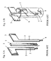
- FIGS. 11A and 11B A further measuring cell assembly according to the prior art is disclosed in Document U.S. Pat. No. 6,004,818 of Freilich et al. , which is shown in FIGS. 11A and 11B .
- FIG. 11A illustrates an explosive view of a part of a measuring cell device comprising an insulator 1, which is sandwiched between two flag-shaped electrodes 2.
- Each electrode 2 includes a connection tab 3 at one end and a tip 4 at the other end thereof, with a shaft 5 joining the tab 3 and the tip 4 respectively. After joining the two electrodes 2 and insulator 1 together a non-conductive coating is applied to the insulator 1 and to the electrode shafts 5.
- FIG. 11B illustrates a perspective view of a measuring cell device according to the prior art. As shown in FIG. 11B the electrode assembly is fixed within a cuvette 56 using a positional clip 7. Prior to and during measurement, a stir bar 8 is activated to generate a circular flow of sample within the cuvette 6.
- One drawback of the aforementioned measuring cell device is the use of punched sheet metal for the electrodes 2.
- the outline of the electrodes can economically be produced by the process of punching or related methods.
- the surface qualities produced by these methods are relatively poor and vary during the production of large quantities (because of the aging of the punching blades applied during the process).
- the quality of the surfaces, which strongly affect the measurement, are thus strongly varying resulting in high variations between different disposable electrodes.
- a further disadvantage is due to the fact that the complete measuring cell device consists of six different pieces, namely the two electrodes 3, the insulator 1, the coating, a cuvette 6, a positional clip 7 and a stir bar 8. This results in an expensive, complicated production process, which is either labor intensive or requires high investments for an automated assembly line.
- the present invention provides a cartridge device for analysing blood as defined in claim 1.
- cartridge describes the disposable structure applied in the invention. It consists of a cell 9 and an electrode holder 14.
- the cartridge device 20 consists of two main parts 9 and 14 made by particularly injection moulding.
- the one part is a single pieced receiving means and subsequently called cell 9.
- FIG. 1 depicts a cell 9 in a perspective view.
- the cell 9 comprises at least a preferably cylindrical receiving portion or cup portion 10, which is open at one face side, holding a sample during the analysis.
- the sample is placed into the cup portion 10 of the cell 9 by means of a particularly conical funnel tube 11.
- the cell 9 further comprises a jack portion 12 adjacent to the cup portion 10 and separated therefrom by a stopping wall 27. Together with an electrode holder 14, described later in further details (see FIG. 2 ), the jack portion 12 forms a jack 18 (see FIG. 3 ), in which a plug 22 (described later in further details) is arranged and which allows the electrical connection of the cell 9 to an instrument, for example an analyser.
- a guiding rail 13 is formed on both sides of the funnel tube 11 of the cell 9, respectively, for guiding the electrode holder 14 into a secure and tight connection with the cell 9 as shown in FIG. 4 .
- the whole cell 9 is formed in a way that it can be easily unmoulded with a two part injection moulding mould. This requires that the cup 9 does not form any undercuts and that the outer and inner surfaces are at least slightly conical.
- the cell 9 has three different functional portions, it can inexpensively be produced as one part using injection moulding. This minimises production costs on the one hand and the need for manual handling for the use on the other hand.
- the cell 9 is in particular produced of blood compatible material such as polystyrene.
- Other usable materials are polymethyl methacrylate (PMMA) or polyethylene.
- PMMA polymethyl methacrylate
- the importance of using a blood compatible material is that the blood platelets will not get activated by the contact with the cell material. This allows to activate specifically the platelets as intended for the different test methods performed.
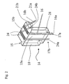
- the other part of the cartridge device 20 is the electrode holder 14, illustrated in FIG. 2 in a perspective view.
- the electrode holder 14 consists particularly of a plastic body 15, in which two tiny electrode wire pairs 16, 24 are incorporated.
- Each wire of a wire pair 16, 24 has preferably a diameter of about 0.1-0.5 mm, most preferably 0.3 mm.
- the electrode holder 14 comprises especially a L-formed body 15 with a long part 15a and a short part 15b perpendicular to the long part 15a.
- each electrode wire of the electrode pairs 16, 24 protrudes and forms a sensor portion 16a, 24a.
- two sensor portions 16a or 24a form together a sensor unit 17a or 17b.
- the blood platelets adhere on the sensor portions 16a, 24a of the wire pairs 16, 24 and change the electrical impedance between said two wires of a respective wire pair 16 or 24. These measured impedance values can be compared with each other and/or with a predetermined threshold.
- each electrode wire of the electrode pairs 16, 24 protrudes under a predetermined angle, for example 50°, and forms a connector portion 16b, 24b, respectively.
- the electrode holder 14 comprises two linear independent sensor units 17a, 17b, each formed by an electrode wire pair 16, 24.
- the sensor units 17a, 17b are particularly placed symmetrically to each other at the face side of the long part 15a of the body 15 in order to ensure identical flow conditions around each wire pair and acceptable measurement results.
- Preferably the two wires of an electrode pair 16 (24) are positioned parallel to each other and parallel to the wires of another electrode pair 24 (16).
- the electrode holder is preferably inexpensively produced by injection moulding. This requires to insert the wires of the electrode pairs 16, 24 into the mould and to extrusion-coat them by the resin. This poses the problem not to bend the thin wires by the high pressure in the injection mould. Also it is important to automate the process of placing the wires into the mould, thus allowing fully automated production and thus low costs.
- the wires are automatically placed into the mould from a roll, then extrusion coated and afterwards automatically taken out of the mould and then cut into the right dimensions. This also provides the advantage that cable on a roll is less expensive than pre-cut cable bars. It is advantageous to keep the wires under tension during the injection process in order to prevent bending of the thin wires.
- the plastic material used for the electrode holder is preferably a blood compatible material such as polystyrene, PMMA or polyethylene, most preferably polystyrene.
- the material selected for the electrodes or wires needs to fulfil several requirements. It should provide a low electrical resistance. This provides a good electrical connection of the wires in the connection portions 16b, 24b to plugs 22 or equivalent devices and in addition it provides a stronger signal of the analysis.
- the wires are coated by the activated platelets which enhances the electrical resistance between them. When wires of a lower resistance are applied this leads to a stronger resistance change when the wires are coated by the platelets compared to a material with lower conductivity.
- Materials with a high conductivity include for example copper and copper alloys (copper-silver alloy, copper-magnesium alloy).
- the wire material must also not oxidate when contacted to blood, even when different oxidating drugs are present. This requires the surface of the wires 15 to have a low tendency to oxidate.
- Such materials are for example precious metals such as platin, gold, silver.
- the named materials with a high conductivity (copper and copper alloys) have a high tendency to oxidate.
- the precious metals are too expensive to be used for the production of a single use cartridge.
- a low cost wire material with a high conductivity preferably a silver-copper alloy comprising 0.2-2 % silver, most preferably 0.9% silver
- a precious material such as silver
- a wire is obtained which is economical, which provides a good electrical impedance and which is also sufficiently resistant to oxidation during the analysis.
- Other coatings made of gold, platin or other precious metals can be also applied.
- the electrodes are preferably wires having a circular cross-section.
- the inventors have tested diameters between 0,1 mm and 0,50 mm. The signal turns out to become weaker with increasing diameter, so that the electrodes should be thin.
- the electrode holder is manufactured by injection moulding which requires tearproof rods, i.e. the rods should not be to thin.
- the optimal value for diameter of the electrodes which encompasses these two aspects turned out to be 0,3 mm.
- the length of the ends of the electrodes which stand out of the electrode holder 14 is preferably 4 mm.
- the inventors have tested lengths between 2 mm and 6 mm. It turned out, that the longer the ends are, the weaker the signal becomes, so that short ends are preferred. However, when the ends become too short, the production of the electrode holder becomes more complicated, so that an optimal length is about 4 mm.
- a spacing of 0,5 - 1 mm between the electrode wires was found to provide optimal signal and reproducibility.
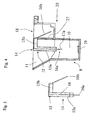
- the electrode wires are preferably bended two times as is best seen in FIGS. 3 and 4 . This bending ensures that the ends of the electrodes form together with the jack portion 12 of the cell 9 a jack.
- the inventors use preferably a geometry consistent with the normed jack RJ12. This allows to use the standard RJ12 plug to connect the cartridge device 20 to an analyser just by putting the plug into the jack portion 18.
- the wires 16, 24 are bended for example under an angle of at least 90° as shown in FIG. 3 .
- the electrode holder 14 is connected to the cell 9 by guiding a guiding part 28 of the holder 14 in said respective guiding rails 13 of the funnel tube 11 of the cell 9 until it contacts the upper edge of the stopping wall 27.
- FIGS. 4 to 6 illustrate an assembled cartridge device 20 in a sectional side view, a top plan view and a perspective view according to a preferred first embodiment of the present invention.
- a magnetic or paramagnetic stir bar 19 for stirring the blood sample is placed into the cup portion 10. Then the whole device is packed into appropriate means for storage and shipping to the customer.
- the receptacle is preferably heated to 37° to ensure that the analysis takes place under standardized and physiological temperature conditions.
- the filling amount of the blood sample is preferably large enough to ensure that the ends of the electrode wires projecting from the face side of the long part 15a of the body 15 are completely covered.
- the preferred means for stirring the sample is the use of electromagnets that are alternately turned on and off and therefore induce a rotation of the stir bar 19.
- the stir bar 19 can comprise a Teflon coated stir bar, steel or siliconized steel. Siliconized stainless steel is the preferred material, as it is less expensive than Teflon coated stir bars.
- Non-coated stir bars can alter the platelet activation due to the contact and adhesion of platelets to the thrombogenic steel material.
- permanent magnets that are rotated by adequate means or other means for inducing rotation of the sample (such as ultrasound, orbital movements of the cup) can be applied as obvious to a person skilled in the art.
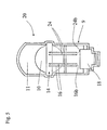
- FIG. 7 shows a sectional view of an assembled cartridge device with a connected plug 22 according to a preferred embodiment of the present invention.
- the plug 22 is preferably a standard plug, which comprises particularly a conductive element 22 contacting the contact regions 16b, 24b, i.e. the plug portions 21a and 21b of the electrode wire pairs 16 and 24.
- the plug 22 is connected to an analyser (not shown) by means of a connection cable 23 and allows the signal of the analysis to be transferred from the cartridge device 20 to the analyser.
- the analyser continuously records the impedance change on both sensor units 17a and 17b.
- the impedance change of both sensor units 17a and 17b will be identical or nearly identical.
- An automatic algorithm in the software distinguishes acceptable from non-acceptable variation between the results of the sensor units 17a and 17b and automatically stops the analysis if required.
- an acceptable variation is recorded, for example the mean value of the two determinations is reported to the user. This leads to significantly improved precision. The rate of wrong diagnosis is significantly decreased compared to single analysis units.
- the user disconnects the plug 22 from the cartridge device 20 and discards it.
- FIG. 8 is a perspective view.
- the cell 9 according to the second embodiment is identical to the previous embodiment and therefore it is referred to the above evaluations.
- the electrode holder 14 comprises three sensor units 17a, 17b, 17c, which are linearly arranged to each other.
- Each sensor unit consists of a pair of electrode wires 16, 24 and 25, respectively. Due to the linear arrangement the electrode wire pair 24 is in the middle of the two remaining electrode wire pairs 16 and 25 and is exposed to a significantly lower blood flow when compared to the outer electrode wire pairs 16 and 25.
- the second embodiment it is possible to compare platelet adhesion and aggregation under varying flow conditions. It is obvious to a person skilled in the art that by variations of the number and geometric arrangement of the test units the flow conditions under which the platelets are analysed can be varied and also differentiated software algorithms can be applied.
- the cell 9 is identical to the previous embodiments and therefore it is referred to the above evaluations.
- the electrode holder 14 comprises four sensor units 17a, 17b, 17c, 17d. These sensor units are linearly arranged to each other. Each sensor unit 17a, 17b, 17c and 17d consists of a pair of electrode wires 16, 24, 25 and 26, respectively. Due to the linear arrangement the middle two electrode wire pairs 24 and 25 are exposed to a lower blood flow compared to the outer electrode wires 16 and 26. Hence according to the third embodiment it is possible to make a double-determination of the platelet aggregation under low and high blood flow conditions, referring to the flow conditions of blood in vessels with small and large diameter.
- FIG. 10 illustrates a top plan sectional view of a cartridge device 20 according to a fourth embodiment of the present invention.
- the cell 9 is identical to the aforementioned embodiments and therefore it is referred to the above evaluations.
- the electrode holder 14 is formed to allow a circular arrangement ( FIG. 8 ) of several sensor units.
- three sensor units 17a, 17b and 17c are arranged at the same radial location in the blood sample, i.e. in the receiving portion 10, and exposed to the identical or nearly identical blood flow, which allows to directly compare the signals.
- the analyser independently records the changes in conductivity between the wire pairs of the three sensor units 17a, 17b and 17c.
- three independent results are obtained.
- the mean or median value is reported to the user, resulting in an enhanced precision of the analysis when compared to the prior art and to inventive embodiments containing only two independent sensor units.
Abstract
Description
- The present invention relates to a cartridge device for blood analysis.
- Though the present invention can be used in many fields of measuring blood it will be described in regard to measuring the platelet function of blood in the following.
- Blood consists of cells suspended in so called plasma, a protein rich fluid. The major groups.of cells in the blood are red cells, white cells and platelets. The platelets are responsible for plugging gaps or holes in the blood vessel wall. This is achieved by a mechanism called aggregation-adhesion reaction. When the platelets aggregate, they become sticky and, as a result thereof, they stick to each another and to the damaged tissue. Usually this happens when the platelets come into contact with certain materials and chemicals, especially those related to damaged cells.
- Platelet adhesion to injured blood vessels is an essential property in order to close wounds and thus to ensure survival of the organism after for example a trauma.
- However the adhesion and aggregation of platelets can also be extremely dangerous when the platelets mistake an aged or inflamed vessel for a vascular injury and thus impair blood flow in tissues of vital importance. Such processes take place during a myocardial infarction or a stroke, diseases which account for more deaths in the industrialised nations than infectious diseases or cancer.
- An increasing number of patients who have suffered myocardial infarction or stroke as well as patients who are at high risk for these events is treated for a reduced tendency of their platelets to aggregate with substances called "anti-platelet agents". Besides their beneficial effect - to reduce the incidence of platelets closing vitally important vessels - these drugs may also induce bleeding. However a larger danger is due to the fact that in some of the patients the drugs seem not to work properly. Current studies have shown that up to 25% of the patients treated do not adequately respond to this treatment.
- It is thus not only of scientific interest, but also of high clinical importance to be able to test the function of the platelets and the individual response to drugs which interfere with their activation. Several techniques according to the prior art are used to analyse platelet functions or the action of anti-platelet drugs.
- An early but still widely used development is the Born aggregometer which measures the change of light transmission of platelet-rich plasma (PRP) during the process of aggregation. Platelet rich-plasma is obtained by centrifugation of anticoagulated blood at a relatively low speed, which removes the heavy (hemoglobin-filled) red cells from the plasma, but leaves the much lighter platelets in the solution. Because of the platelet content the light transmission of PRP is relatively low. When the platelets aggregate the optical density is reduced, because the platelets form few large aggregates, which interfere much less with the light transmitted through the sample.
- A disadvantage of this technique is the necessity of producing PRP, whose extraction is a complicated, time-consuming and thus expensive procedure. Furthermore, the aggregation of platelets is not measured in its natural environment, blood, thus the influence of red and white cells on the platelets is not measured.
- Other methods disclosed in documents
US 4,604,894 of Kratzer and Born ,US 6,010,911 of Baugh et al. andUS 5,922,551 of Durbin et al. require relatively complex and expensive cartridges interfering with the use of these techniques for routine testing. - Document
U.S. Pat. No. 4,319,194 of Cardinal et al. discloses a platelet aggregation analysis typically performed in whole blood by measuring the electric impedance between two electrodes, being immersed in a sample. During initial contact with the blood or PRP, the electrodes are coated with a monolayer of platelets. When an aggregating agent is added, platelets gradually accumulate on the monolayer coating, increasing the impedance between the electrodes. The change in impedance is recorded as a function of time. It is prefered that the electrodes comprise precious metals since base metals drift in blood-saline mixtures. - One disadvantage of precious metal electrodes is high costs. Hence they are too expensive to be disposable. Therefore, the electrode assembly must be cleaned by hand between tests, exposing the operator to contact with the sample, and thus potentially exposing the operator to diseases transmitted through the fluids contained in the sample. Since diseases such as hepatitis and AIDS can be transmitted through handling of blood products, there is an understandable reluctance on the part of medical professionals to handle blood, blood products and objects contamined therewith.
- A further disadvantage of this structure is due to the fact that the electrodes of the aggregometer have to be handled by the user during the cleaning procedure, potentially disturbing the adjustment of the distance between the electrodes, causing inconsistent results. Furthermore each electrode requires exact placement of the wires during fabrication, making the final product expensive.
- Document
U.S. Pat. No. 4,591,793 of Freilich describes a substitution of the wire electrodes by a conductive ink printed on a plastic non-reactive base. - However this device is detrimental due to the fact that the platelets have difficulties in adhering to the exposed conductive surface of the Freilich device. Sometimes the aggregated platelets break off the surface, causing a sudden change in impedance. Hence the measured results by the device are inconsistent and not reproducible.
- A further measuring cell assembly according to the prior art is disclosed in Document
U.S. Pat. No. 6,004,818 of Freilich et al. , which is shown inFIGS. 11A and 11B . -
FIG. 11A illustrates an explosive view of a part of a measuring cell device comprising aninsulator 1, which is sandwiched between two flag-shaped electrodes 2. Eachelectrode 2 includes aconnection tab 3 at one end and atip 4 at the other end thereof, with ashaft 5 joining thetab 3 and thetip 4 respectively. After joining the twoelectrodes 2 andinsulator 1 together a non-conductive coating is applied to theinsulator 1 and to theelectrode shafts 5. -
FIG. 11B illustrates a perspective view of a measuring cell device according to the prior art. As shown inFIG. 11B the electrode assembly is fixed within a cuvette 56 using a positional clip 7. Prior to and during measurement, a stir bar 8 is activated to generate a circular flow of sample within thecuvette 6. - One drawback of the aforementioned measuring cell device is the use of punched sheet metal for the
electrodes 2. The outline of the electrodes can economically be produced by the process of punching or related methods. However the surface qualities produced by these methods are relatively poor and vary during the production of large quantities (because of the aging of the punching blades applied during the process). The quality of the surfaces, which strongly affect the measurement, are thus strongly varying resulting in high variations between different disposable electrodes. - A further disadvantage is due to the fact that the complete measuring cell device consists of six different pieces, namely the two
electrodes 3, theinsulator 1, the coating, acuvette 6, a positional clip 7 and a stir bar 8. This results in an expensive, complicated production process, which is either labor intensive or requires high investments for an automated assembly line. - Additionally the measuring cell device of Freilich does not overcome the relatively high variation reported for whole blood aggregometry. In document
US 6,004,818 a variation of around 10-15% between multiple measurements is reported for said measuring cell assembly. - Hence it is an object of the present invention to provide a cartridge device which overcomes the above mentioned drawbacks, particularly to provide a cartridge device which is economical, reproducible, safe and easy to use.
- It is another object of the present invention to eliminate the limited reproducibility of previous methods according to the prior art for the measurement of aggregation in whole blood.
- It is still another object of the present invention to provide a cartridge device which is accurate and so economical to produce that it can be discarded after each test.
- It is still another object of the present invention to provide a cartridge device which can be provided ready to use, so the application of the technique is simple and contains only few user-related sources of error and variation.
- The present invention provides a cartridge device for analysing blood as defined in
claim 1. - The invention may be further understood by reference to the drawings, wherein:
- FIG. 1
- is a perspective view of a cell for the present invention;
- FIG. 2
- is a perspective view of an electrode holder for the present invention (with double determination technique);
- FIG. 3
- is a side view of an electrode holder for the present invention (double, linear triple or linear quadruple detection technique);
- FIG. 4
- is a side view of the cartridge according to certain embodiments of the present invention (double, linear triple or linear quadruple detection technique);
- FIG. 5
- is a top plan view of a cartridge according to a first embodiment of the present invention (with double determination technique);
- FIG. 6
- is a perspective view of the cartridge according to the first embodiment of the present invention (with double determination technique);
- FIG. 7
- is a sectional view of a cartridge device with attached plug and cable according to an embodiment of the present invention;
- FIG. 8
- is a perspective view of a cartridge device according to a second embodiment of the present invention (with triple determination technique;
- FIG. 9
- is a perspective view of a cartridge device according to a third embodiment of the present invention (with linear quadruple determination technique);
- FIG. 10
- is a top plan view of a cartridge device according to a fourth embodiment of the present invention (with circular triple determination technique;
- FIG. 11A
- is an explosive view of a part of a cartridge device according to the prior art; and
- FIG. 11B
- is an perspective view of a cartridge device according to the prior art.
- In all figures like reference numerals are used to demote like elements and/or like functions of respective elements as long as nothing else is stated. It should be noticed that in the following the term cartridge describes the disposable structure applied in the invention. It consists of a
cell 9 and anelectrode holder 14. - The
cartridge device 20 consists of twomain parts cell 9. -
FIG. 1 depicts acell 9 in a perspective view. Thecell 9 comprises at least a preferably cylindrical receiving portion orcup portion 10, which is open at one face side, holding a sample during the analysis. The sample is placed into thecup portion 10 of thecell 9 by means of a particularlyconical funnel tube 11. - The
cell 9 further comprises ajack portion 12 adjacent to thecup portion 10 and separated therefrom by a stoppingwall 27. Together with anelectrode holder 14, described later in further details (seeFIG. 2 ), thejack portion 12 forms a jack 18 (seeFIG. 3 ), in which a plug 22 (described later in further details) is arranged and which allows the electrical connection of thecell 9 to an instrument, for example an analyser. - A guiding
rail 13 is formed on both sides of thefunnel tube 11 of thecell 9, respectively, for guiding theelectrode holder 14 into a secure and tight connection with thecell 9 as shown inFIG. 4 . - Preferably and as shown in
FIG. 1 thewhole cell 9 is formed in a way that it can be easily unmoulded with a two part injection moulding mould. This requires that thecup 9 does not form any undercuts and that the outer and inner surfaces are at least slightly conical. Although thecell 9 has three different functional portions, it can inexpensively be produced as one part using injection moulding. This minimises production costs on the one hand and the need for manual handling for the use on the other hand. - The
cell 9 is in particular produced of blood compatible material such as polystyrene. Other usable materials are polymethyl methacrylate (PMMA) or polyethylene. The importance of using a blood compatible material is that the blood platelets will not get activated by the contact with the cell material. This allows to activate specifically the platelets as intended for the different test methods performed. - The other part of the
cartridge device 20 is theelectrode holder 14, illustrated inFIG. 2 in a perspective view. Theelectrode holder 14 consists particularly of aplastic body 15, in which two tiny electrode wire pairs 16, 24 are incorporated. Each wire of awire pair - The
electrode holder 14 comprises especially a L-formedbody 15 with along part 15a and ashort part 15b perpendicular to thelong part 15a. At the face side of thelong part 15a of theelectrode holder 14 each electrode wire of the electrode pairs 16, 24 protrudes and forms asensor portion sensor portions sensor unit sensor units sensor portions respective wire pair - At the face side of the
short part 15b of theelectrode holder 14 each electrode wire of the electrode pairs 16, 24 protrudes under a predetermined angle, for example 50°, and forms aconnector portion - The
electrode holder 14 comprises two linearindependent sensor units electrode wire pair sensor units long part 15a of thebody 15 in order to ensure identical flow conditions around each wire pair and acceptable measurement results. Preferably the two wires of an electrode pair 16 (24) are positioned parallel to each other and parallel to the wires of another electrode pair 24 (16). - The electrode holder is preferably inexpensively produced by injection moulding. This requires to insert the wires of the electrode pairs 16, 24 into the mould and to extrusion-coat them by the resin. This poses the problem not to bend the thin wires by the high pressure in the injection mould. Also it is important to automate the process of placing the wires into the mould, thus allowing fully automated production and thus low costs. Preferably the wires are automatically placed into the mould from a roll, then extrusion coated and afterwards automatically taken out of the mould and then cut into the right dimensions. This also provides the advantage that cable on a roll is less expensive than pre-cut cable bars. It is advantageous to keep the wires under tension during the injection process in order to prevent bending of the thin wires.
- It is also advantageous to keep the
body 15 of theelectrode holder 14 thin, as it is shown inFIG. 2 . This leads to reduced pressure requirements in the injection process and thus also to a lower tendency to bend the wires of the electrode wire pairs 16, 24. A thickness of 1-5 mm of thebody 15 is preferred most. The plastic material used for the electrode holder is preferably a blood compatible material such as polystyrene, PMMA or polyethylene, most preferably polystyrene. - The material selected for the electrodes or wires needs to fulfil several requirements. It should provide a low electrical resistance. This provides a good electrical connection of the wires in the
connection portions plugs 22 or equivalent devices and in addition it provides a stronger signal of the analysis. In thesensor portions - However the wire material must also not oxidate when contacted to blood, even when different oxidating drugs are present. This requires the surface of the
wires 15 to have a low tendency to oxidate. Such materials are for example precious metals such as platin, gold, silver. The named materials with a high conductivity (copper and copper alloys) have a high tendency to oxidate. However the precious metals are too expensive to be used for the production of a single use cartridge. According to the present invention it was found that by coating a low cost wire material with a high conductivity (preferably a silver-copper alloy comprising 0.2-2 % silver, most preferably 0.9% silver) with a precious material such as silver (preferably using a coating of 0.5-20 g / kg, most preferably 2 g/ kg) a wire is obtained which is economical, which provides a good electrical impedance and which is also sufficiently resistant to oxidation during the analysis. Other coatings made of gold, platin or other precious metals can be also applied. - The electrodes are preferably wires having a circular cross-section. The inventors have tested diameters between 0,1 mm and 0,50 mm. The signal turns out to become weaker with increasing diameter, so that the electrodes should be thin. The electrode holder is manufactured by injection moulding which requires tearproof rods, i.e. the rods should not be to thin. The optimal value for diameter of the electrodes which encompasses these two aspects turned out to be 0,3 mm.
- The length of the ends of the electrodes which stand out of the
electrode holder 14 is preferably 4 mm. The inventors have tested lengths between 2 mm and 6 mm. It turned out, that the longer the ends are, the weaker the signal becomes, so that short ends are preferred. However, when the ends become too short, the production of the electrode holder becomes more complicated, so that an optimal length is about 4 mm. - A spacing of 0,5 - 1 mm between the electrode wires was found to provide optimal signal and reproducibility.
- The electrode wires are preferably bended two times as is best seen in
FIGS. 3 and 4 . This bending ensures that the ends of the electrodes form together with thejack portion 12 of the cell 9 a jack. In the present case the inventors use preferably a geometry consistent with the normed jack RJ12. This allows to use the standard RJ12 plug to connect thecartridge device 20 to an analyser just by putting the plug into thejack portion 18. - After the injection moulding process the
wires FIG. 3 . - Afterwards the
electrode holder 14 is connected to thecell 9 by guiding a guidingpart 28 of theholder 14 in said respective guiding rails 13 of thefunnel tube 11 of thecell 9 until it contacts the upper edge of the stoppingwall 27. -
FIGS. 4 to 6 illustrate an assembledcartridge device 20 in a sectional side view, a top plan view and a perspective view according to a preferred first embodiment of the present invention. - A magnetic or
paramagnetic stir bar 19 for stirring the blood sample is placed into thecup portion 10. Then the whole device is packed into appropriate means for storage and shipping to the customer. - Before the analysis the user takes the
cartridge device 20 out of the packaging and places it into an appropriate receptacle of the analyser. The receptacle is preferably heated to 37° to ensure that the analysis takes place under standardized and physiological temperature conditions. - The filling amount of the blood sample is preferably large enough to ensure that the ends of the electrode wires projecting from the face side of the
long part 15a of thebody 15 are completely covered. - Appropriate means are placed under the receptacle that induce a stirring motion of the
stir bar 19. The preferred means for stirring the sample is the use of electromagnets that are alternately turned on and off and therefore induce a rotation of thestir bar 19. Thestir bar 19 can comprise a Teflon coated stir bar, steel or siliconized steel. Siliconized stainless steel is the preferred material, as it is less expensive than Teflon coated stir bars. Non-coated stir bars can alter the platelet activation due to the contact and adhesion of platelets to the thrombogenic steel material. Also permanent magnets that are rotated by adequate means or other means for inducing rotation of the sample (such as ultrasound, orbital movements of the cup) can be applied as obvious to a person skilled in the art. - The user then connects a
plug 22, preferably a standard RJ12 plug, to thejack 18 as illustrated inFIG. 7 , which shows a sectional view of an assembled cartridge device with aconnected plug 22 according to a preferred embodiment of the present invention. Theplug 22 is preferably a standard plug, which comprises particularly aconductive element 22 contacting thecontact regions plug portions plug 22 is connected to an analyser (not shown) by means of aconnection cable 23 and allows the signal of the analysis to be transferred from thecartridge device 20 to the analyser. - During the analysis the analyser continuously records the impedance change on both
sensor units sensor units wires sensor units sensor units - After the analysis the user disconnects the
plug 22 from thecartridge device 20 and discards it. - A second preferred embodiment of the
cartridge device 20 is shown inFIG. 8 , which is a perspective view. Thecell 9 according to the second embodiment is identical to the previous embodiment and therefore it is referred to the above evaluations. - However contrary to the first embodiment the
electrode holder 14 according to the second embodiment comprises threesensor units electrode wires electrode wire pair 24 is in the middle of the two remaining electrode wire pairs 16 and 25 and is exposed to a significantly lower blood flow when compared to the outer electrode wire pairs 16 and 25. Hence according to the second embodiment it is possible to compare platelet adhesion and aggregation under varying flow conditions. It is obvious to a person skilled in the art that by variations of the number and geometric arrangement of the test units the flow conditions under which the platelets are analysed can be varied and also differentiated software algorithms can be applied. - According to a third preferred embodiment as shown in a perspective view in
FIG. 9 , thecell 9 is identical to the previous embodiments and therefore it is referred to the above evaluations. - However the
electrode holder 14 according to the third embodiment comprises foursensor units sensor unit electrode wires outer electrode wires -
FIG. 10 illustrates a top plan sectional view of acartridge device 20 according to a fourth embodiment of the present invention. Thecell 9 is identical to the aforementioned embodiments and therefore it is referred to the above evaluations. - However the
electrode holder 14 is formed to allow a circular arrangement (FIG. 8 ) of several sensor units. According to the present arrangement shown inFIG. 10 threesensor units portion 10, and exposed to the identical or nearly identical blood flow, which allows to directly compare the signals. - According to the fourth embodiment the analyser independently records the changes in conductivity between the wire pairs of the three
sensor units -
- 1
- insulator
- 2
- electrode
- 3
- connection tap
- 4
- tip
- 5
- shaft
- 6
- cuvette
- 7
- clip
- 8
- stir bar
- 9
- cell
- 10
- receiving portion/cup portion
- 11
- tunnel tube
- 12
- jack portion
- 13
- guiding rail
- 14
- electrode holder
- 15
- plastic body
- 15a
- long part of body
- 15b
- short part of body
- 16
- first electrode wire pair
- 16a
- sensor portion
- 16b
- connection portion
- 17a
- first sensor unit
- 17b
- second sensor unit
- 17c
- third sensor unit
- 17d
- fourth sensor unit
- 18
- jack
- 19
- stir bar
- 20
- cartridge device
- 21a
- plug portion
- 21b
- plug portion
- 21c
- plug portion
- 21d
- plug portion
- 22
- plug
- 23
- connection cable
- 24
- second electrode wire pair
- 24a
- sensor portion
- 24b
- connection portion
- 25
- third electrode wire pair
- 25a
- sensor portion
- 25b
- connection portion
- 26
- fourth electrode wire pair
- 26a
- sensor portion
- 26b
- connection portion
- 27
- stopping wall
- 28
- guiding part
Claims (24)
- Cartridge device (20) for analysing blood comprising:a cell (9) having a blood receiving portion (10) for receiving a blood sample and a plug or jack receiving portion (12) for receiving a plug or a jack (22);means (19) for circulating said blood sample within said blood receiving portion (10); and an electrode holder (14) having at least one incorporated pair of metal wires (16; 24; 25; 26);wherein the electrode holder (14) is attached to the cell (9) such that one end (16a; 24a; 25a; 26a) of the at least one pair of wires (16; 24; 25; 26) is positioned inside the blood receiving portion (10) and forms a sensor unit (17a; 17b; 17c; 17d) for measuring the electrical impedance between the two electrodes of the at least one pair of wires (16; 24; 25; 26) within a blood sample and that the opposite end (16b; 24b; 25b; 26b) of the at least one pair of wires (16; 24; 25; 26) is positioned inside the plug or jack receiving portion (12) and forms a plug or jack portion (21a; 21b; 21c; 21d) being connectable directly to a plug or jack (22) for an electrical connection of the sensor unit (17a; 17b; 17c; 17d) to an analyser.
- Cartridge device (20) according to claim 1, characterised in that the cell (9) is made as a one-piece cell by injection moulding.
- Cartridge device (20) according to claim 1 or 2, characterised in that the blood receiving portion (10) has a cylindrical shape with one open face side.
- Cartridge device (20) according to at least one of the preceding claims, characterised in that a at least partly conical formed funnel tube (11) is connected to the open face side of the blood receiving portion (10) for filling in the blood sample.
- Cartridge device (20) according to claim 4, characterised in that two guiding rails (13) are positioned on the inner surface of the funnel tube (11) for guiding the electrode holder (14) into position.
- Cartridge device (20) according to claim 4 or 5, characterised in that a stopping wall (27) is positioned between the funnel tube (11) and the plug or jack receiving portion (12) for positioning the electrode holder (14) into a stable position.
- Cartridge device (20) according to at least one of the preceding claims, characterised in that the cell (9) is made of a blood compatible material, such as polystyrene, polymethyl methacrylate (PMMA), polyethylene etc.
- Cartridge device (20) according to at least one of the preceding claims, characterised in that the electrode holder (14) comprises a plastic body (15) which is made by injection moulding.
- Cartridge device (20) according to claim 8, characterised in that the plastic body (15) of the wire holder (14) has a thickness of about 1 to 5 mm.
- Cartridge device (20) according to at least one of the preceding claims, characterised in that the wire holder (14) is made of a blood compatible material such as polystyrene, polymethyl methacrylate (PMMA), polyethylene, etc.
- Cartridge device (20) according to at least one of the preceding claims, characterised in that the wire holder (14) comprises a L-formed body (15) with a long part (15a) and a short part (15b) perpendicular to the long part (15a)
- Cartridge device (20) according to at least one of the preceding claims, characterised in that two pairs of wires (16, 24) are symmetrically incorporated in the wire holder (14) for two independent separate measurement results.
- Cartridge device (20) according to at least one of the claims 1 to 11, characterised in that three pairs of wires (16, 24, 25) are linear incorporated in the electrode holder (14) for three separate measurement results,
wherein one pair of wires (24) is preferably positioned in the middle of the remaining pairs of wires (16, 25) for comparing platelet adhesion and aggregation under varying flow conditions. - Cartridge device (20) according to at least one of the claims 1 to 11, characterised in that four pairs of wires (16, 24, 25, 26) are linear incorporated in the wire holder (24) for four separate measurement results for making a double-determination of the platelet aggregation under low and high blood flow conditions.
- Cartridge device (20) according to at least one of the claims 1 to 11, characterised in that at least three pairs of wires (16, 24, 25) are arranged symmetrically to each other at the same radial position in the blood receiving portion (10).
- Cartridge device (20) according to at least one of the preceding claims, characterised in that the two wires of one pair of wires (16, 24, 25, 26) are positioned parallel to each other and spaced apart from each other.
- Cartridge device (20) according to at least one of the preceding claims, characterised in that two pairs of wires (16, 24, 25, 26) are positioned parallel to each other and spaced apart from each other.
- Cartridge device (20) according to at least one of the preceding claims, characterised in that the wires are made of a first material comprising a high conductivity, which is covered by a second material comprising a high electrical conductivity and being resistant against oxidation.
- Cartridge device (20) according to claim 18, characterised in that the first material is copper, copper alloy, such as copper-silver alloy, copper-magnesium alloy or such like, preferably a silver-copper alloy comprising 0,2 to 2 % silver, most preferably 0,9 % silver.
- Cartridge device (20) according to claim 18 or 19, characterised in that the second material is a precious metal such as silver, platin, gold or such like.
- Cartridge device (20) according to claim 20, characterised in that the second precious metal is a silver coating in the range of about 0,5 to 20 g/kg, most preferably 2 g/kg.
- Cartridge device (20) according to at least one of claims 18 to 21, characterised in that the wires have a diameter of about 0,1 to 0,5 mm, preferably 0,3 mm.
- Cartridge device (20) according to at least one of the preceding claims, characterised in that the means (19) are a stir bar (19), which is made of steel, siliconized steel, Teflon or Teflon-coated, preferably siliconized stainless steel, wherein the stir bar (19) is for example actuated by permanent magnets.
- Cartridge device (20) according to at least one of the preceding claims, characterised in that the plug or jack receiving portion (12) is suitably formed for being connectable directly to a standard RJ12 plug (22).
Priority Applications (5)
| Application Number | Priority Date | Filing Date | Title |
|---|---|---|---|
| ES10153678T ES2425082T3 (en) | 2003-12-16 | 2003-12-16 | Blood test method |
| AT10153677T ATE545860T1 (en) | 2003-12-16 | 2003-12-16 | CONNECTOR MODULE FOR BLOOD ANALYSIS |
| EP10153678.7A EP2182345B1 (en) | 2003-12-16 | 2003-12-16 | Method for analysing blood |
| EP10153677A EP2187201B1 (en) | 2003-12-16 | 2003-12-16 | Cartridge device for blood analysis |
| ES10153677T ES2382423T3 (en) | 2003-12-16 | 2003-12-16 | Cartridge device for blood analysis |
Applications Claiming Priority (1)
| Application Number | Priority Date | Filing Date | Title |
|---|---|---|---|
| PCT/EP2003/014329 WO2005059532A1 (en) | 2003-12-16 | 2003-12-16 | Cartridge device for blood analysis |
Related Child Applications (2)
| Application Number | Title | Priority Date | Filing Date |
|---|---|---|---|
| EP10153677.9 Division-Into | 2010-02-16 | ||
| EP10153678.7 Division-Into | 2010-02-16 |
Publications (3)
| Publication Number | Publication Date |
|---|---|
| EP1702207A1 EP1702207A1 (en) | 2006-09-20 |
| EP1702207B1 true EP1702207B1 (en) | 2010-02-17 |
| EP1702207B8 EP1702207B8 (en) | 2010-05-19 |
Family
ID=34684495
Family Applications (1)
| Application Number | Title | Priority Date | Filing Date |
|---|---|---|---|
| EP03785839A Expired - Lifetime EP1702207B8 (en) | 2003-12-16 | 2003-12-16 | Cartridge device for blood analysis |
Country Status (8)
| Country | Link |
|---|---|
| US (4) | US7901629B2 (en) |
| EP (1) | EP1702207B8 (en) |
| AT (1) | ATE458194T1 (en) |
| AU (1) | AU2003294867B2 (en) |
| CA (1) | CA2547544C (en) |
| DE (1) | DE60331376D1 (en) |
| ES (1) | ES2340378T3 (en) |
| WO (1) | WO2005059532A1 (en) |
Families Citing this family (43)
| Publication number | Priority date | Publication date | Assignee | Title |
|---|---|---|---|---|
| AU2003294867B2 (en) * | 2003-12-16 | 2010-03-11 | F. Hoffmann-La Roche Ag | Cartridge device for blood analysis |
| DE102005026052B3 (en) * | 2005-06-07 | 2007-03-29 | Gestra Ag | Conductivity measuring cell, conductivity measuring device and method for conductivity measurement |
| EP2053387A1 (en) * | 2007-10-22 | 2009-04-29 | Centre National de la Recherche Scientifique | Test device for platelet aggregation detection |
| DE502008001521D1 (en) * | 2008-04-22 | 2010-11-25 | Holger Behnk | aggregometers |
| ATE551114T1 (en) * | 2008-10-13 | 2012-04-15 | Membrane S R L | MONITORING THE OPERATION OF FLUID TREATMENT SYSTEMS |
| US8448499B2 (en) | 2008-12-23 | 2013-05-28 | C A Casyso Ag | Cartridge device for a measuring system for measuring viscoelastic characteristics of a sample liquid, a corresponding measuring system, and a corresponding method |
| DE102010029555A1 (en) * | 2010-06-01 | 2011-12-01 | Robert Bosch Gmbh | Apparatus for treating a liquid |
| US8617468B2 (en) * | 2011-10-18 | 2013-12-31 | Chrono-Log Corporation | Platelet aggregation test and device |
| US9075042B2 (en) | 2012-05-15 | 2015-07-07 | Wellstat Diagnostics, Llc | Diagnostic systems and cartridges |
| US9625465B2 (en) | 2012-05-15 | 2017-04-18 | Defined Diagnostics, Llc | Clinical diagnostic systems |
| US9213043B2 (en) | 2012-05-15 | 2015-12-15 | Wellstat Diagnostics, Llc | Clinical diagnostic system including instrument and cartridge |
| US8772040B2 (en) * | 2012-08-31 | 2014-07-08 | Korea University Research And Business Foundation | Apparatus and method of platelet multi-function analysis, and micro stirring chip |
| JP2014115256A (en) * | 2012-12-12 | 2014-06-26 | Sony Corp | Container for electrical measurement, apparatus for electrical measurement, and method for electrical measurement |
| US10175225B2 (en) | 2014-09-29 | 2019-01-08 | C A Casyso Ag | Blood testing system and method |
| US10288630B2 (en) | 2014-09-29 | 2019-05-14 | C A Casyso Gmbh | Blood testing system and method |
| US10816559B2 (en) | 2014-09-29 | 2020-10-27 | Ca Casyso Ag | Blood testing system and method |
| US10539579B2 (en) | 2014-09-29 | 2020-01-21 | C A Casyso Gmbh | Blood testing system and method |
| US9891209B2 (en) * | 2015-05-29 | 2018-02-13 | C A Casyso Gmbh | Electrode assembly for measurement of platelet function in whole blood |
| CN108027335B (en) | 2015-06-25 | 2021-05-04 | 罗斯韦尔生物技术股份有限公司 | Biomolecule sensor and method |
| EP3130910A1 (en) * | 2015-08-11 | 2017-02-15 | Centre National De La Recherche Scientifique | Adaptation device for adapting an uv-vis cuvette to perform in-situ spectroanalytical measurements in a controlled atmosphere |
| US10953376B2 (en) * | 2015-09-03 | 2021-03-23 | Tetracore, Inc. | Device and method for mixing and bubble removal |
| FR3043780B1 (en) | 2015-11-16 | 2017-12-15 | Hospices Civils Lyon | METHOD FOR DIAGNOSING ANOMALIES OF BLOOD COAGULATION |
| ES2717112T3 (en) * | 2015-11-25 | 2019-06-19 | C A Casyso Gmbh | System and procedure for mixing and analyzing a liquid |
| EP3408220A4 (en) | 2016-01-28 | 2019-09-04 | Roswell Biotechnologies, Inc | Methods and apparatus for measuring analytes using large scale molecular electronics sensor arrays |
| JP7080489B2 (en) | 2016-01-28 | 2022-06-06 | ロズウェル バイオテクノロジーズ,インコーポレイテッド | Ultra-parallel DNA sequencer |
| WO2017139493A2 (en) | 2016-02-09 | 2017-08-17 | Roswell Biotechnologies, Inc. | Electronic label-free dna and genome sequencing |
| US10597767B2 (en) | 2016-02-22 | 2020-03-24 | Roswell Biotechnologies, Inc. | Nanoparticle fabrication |
| US9829456B1 (en) * | 2016-07-26 | 2017-11-28 | Roswell Biotechnologies, Inc. | Method of making a multi-electrode structure usable in molecular sensing devices |
| US10473674B2 (en) | 2016-08-31 | 2019-11-12 | C A Casyso Gmbh | Controlled blood delivery to mixing chamber of a blood testing cartridge |
| WO2018085496A2 (en) * | 2016-11-02 | 2018-05-11 | Atantares Corp. | Methods and systems for micro platelet function testing using an integrated miniaturized platelet function analyzer |
| JP6414234B2 (en) * | 2017-01-05 | 2018-10-31 | ソニー株式会社 | Electrical measurement container, electrical measurement device, and electrical measurement method |
| CA3052062A1 (en) | 2017-01-10 | 2018-07-19 | Roswell Biotechnologies, Inc. | Methods and systems for dna data storage |
| KR20230158636A (en) | 2017-01-19 | 2023-11-20 | 로스웰 바이오테크놀로지스 인코포레이티드 | Solid state sequencing devices comprising two dimensional layer materials |
| US10508296B2 (en) | 2017-04-25 | 2019-12-17 | Roswell Biotechnologies, Inc. | Enzymatic circuits for molecular sensors |
| CN110546276A (en) | 2017-04-25 | 2019-12-06 | 罗斯威尔生命技术公司 | Enzyme circuit for molecular sensors |
| EP3622086A4 (en) | 2017-05-09 | 2021-04-21 | Roswell Biotechnologies, Inc | Binding probe circuits for molecular sensors |
| US10843185B2 (en) * | 2017-07-12 | 2020-11-24 | Ca Casyso Gmbh | Autoplatelet cartridge device |
| KR20200039795A (en) | 2017-08-30 | 2020-04-16 | 로스웰 바이오테크놀로지스 인코포레이티드 | Progressive enzyme molecular electronic sensors for DNA data storage |
| WO2019075100A1 (en) | 2017-10-10 | 2019-04-18 | Roswell Biotechnologies, Inc. | Methods, apparatus and systems for amplification-free dna data storage |
| JP6791220B2 (en) * | 2018-09-18 | 2020-11-25 | ソニー株式会社 | Electrical measuring container, electrical measuring device and electrical measuring method |
| DE102018128723A1 (en) * | 2018-11-15 | 2020-05-20 | Endress+Hauser Conducta Gmbh+Co. Kg | Cuvette, preferably a flow-through cuvette for an optical measuring device and method for its operation |
| CN110095521B (en) * | 2019-05-13 | 2022-08-23 | 京东方科技集团股份有限公司 | Centrifuge tube, detection system and detection method |
| AU2022209851A1 (en) * | 2021-01-25 | 2023-08-10 | Trividia Health, Inc. | Biosensor for determination of hemoglobin |
Citations (2)
| Publication number | Priority date | Publication date | Assignee | Title |
|---|---|---|---|---|
| EP0909949A2 (en) * | 1997-10-17 | 1999-04-21 | Gebrüder Heyl Analysentechnik GmbH & Co. KG | Sensor for measuring the electrical conductivity of a liquid medium |
| US6238555B1 (en) * | 1997-11-07 | 2001-05-29 | Bioquest | Amperometric halogen control system |
Family Cites Families (24)
| Publication number | Priority date | Publication date | Assignee | Title |
|---|---|---|---|---|
| DE331410C (en) * | 1919-06-22 | 1921-01-07 | Siemens & Halske Akt Ges | Device for measuring the electrical conductivity of liquids |
| US2555937A (en) * | 1949-08-25 | 1951-06-05 | Robert L Rosenthal | Method and apparatus for measuring resistance of blood during clotting |
| GB1299363A (en) | 1968-09-27 | 1972-12-13 | Amiram Ur | Monitoring of chemical, bio-chemical and biological reactions, particularly blood-clotting |
| US3671012A (en) * | 1970-03-16 | 1972-06-20 | Continental Oil Co | Grease compositions containing polymers |
| US3674012A (en) | 1970-04-17 | 1972-07-04 | American Optical Corp | Blood coagulation detection device |
| US3810806A (en) * | 1971-06-25 | 1974-05-14 | H Swartz | Thermoplastic heat sealing apparatus |
| US3840806A (en) * | 1973-08-20 | 1974-10-08 | G Stoner | Instrument for measuring blood clotting times |
| US4123701A (en) * | 1976-07-01 | 1978-10-31 | United States Surgical Corporation | Disposable sample card having a well with electrodes for testing a liquid sample |
| FI793043A (en) * | 1978-10-02 | 1980-04-03 | Wellcome Found | OIL ANCHORING FOER AOTERGIVANDE AV TROMBOSYTANHOPNING |
| GB2049199B (en) * | 1979-04-26 | 1983-11-16 | Gr International Electronics L | Bacterial activity sensing probe |
| DE3247815C2 (en) * | 1982-12-23 | 1985-10-17 | Gustav Viktor Rudolf Prof. London Born | Device for measuring the bleeding time in vitro |
| US4591793A (en) * | 1984-06-14 | 1986-05-27 | Freilich Arthur H | Aggregometer electrode structures |
| FR2664981B1 (en) * | 1990-07-20 | 1994-04-29 | Serbio | DEVICE FOR DETECTING THE CHANGE IN VISCOSITY OF A LIQUID ELECTROLYTE BY THE EFFECT OF DEPOLARIZATION. |
| WO1997011744A1 (en) * | 1995-09-29 | 1997-04-03 | Becton Dickinson And Company | Low-cost electrodes for an iontophoretic device |
| US5922551A (en) * | 1997-03-20 | 1999-07-13 | Accumetrics, Inc. | Agglutrimetric platelet binding assays in blood |
| US6010911A (en) * | 1997-04-30 | 2000-01-04 | Medtronic, Inc. | Apparatus for performing a heparin-independent high sensitivity platelet function evaluation technique |
| US6046051A (en) * | 1997-06-27 | 2000-04-04 | Hemosense, Inc. | Method and device for measuring blood coagulation or lysis by viscosity changes |
| US6004818A (en) * | 1997-08-07 | 1999-12-21 | Chrono-Log Corporation | Aggregometer with disposable test cell |
| US7021122B1 (en) * | 1998-03-19 | 2006-04-04 | Orgenics Biosensors Ltd. | Device for the determination of blood clotting by capacitance or resistance |
| NL1016247C2 (en) | 2000-09-22 | 2002-03-25 | Martil Instr B V | Heart-lung machine provided with an electrical impedance measurement device for signaling microemboli and / or fibrinogen concentration. |
| US7291310B2 (en) * | 2002-12-17 | 2007-11-06 | The Regents Of The University Of Michigan | Microsystem for determining clotting time of blood and low-cost, single-use device for use therein |
| AU2003294867B2 (en) | 2003-12-16 | 2010-03-11 | F. Hoffmann-La Roche Ag | Cartridge device for blood analysis |
| US8617468B2 (en) * | 2011-10-18 | 2013-12-31 | Chrono-Log Corporation | Platelet aggregation test and device |
| US8772040B2 (en) * | 2012-08-31 | 2014-07-08 | Korea University Research And Business Foundation | Apparatus and method of platelet multi-function analysis, and micro stirring chip |
-
2003
- 2003-12-16 AU AU2003294867A patent/AU2003294867B2/en not_active Ceased
- 2003-12-16 CA CA2547544A patent/CA2547544C/en not_active Expired - Fee Related
- 2003-12-16 US US10/583,062 patent/US7901629B2/en active Active
- 2003-12-16 WO PCT/EP2003/014329 patent/WO2005059532A1/en active Application Filing
- 2003-12-16 ES ES03785839T patent/ES2340378T3/en not_active Expired - Lifetime
- 2003-12-16 EP EP03785839A patent/EP1702207B8/en not_active Expired - Lifetime
- 2003-12-16 DE DE60331376T patent/DE60331376D1/en not_active Expired - Lifetime
- 2003-12-16 AT AT03785839T patent/ATE458194T1/en not_active IP Right Cessation
-
2011
- 2011-02-17 US US13/029,575 patent/US8465978B2/en not_active Expired - Lifetime
- 2011-02-17 US US13/029,553 patent/US8591816B2/en not_active Expired - Lifetime
-
2013
- 2013-11-22 US US14/087,823 patent/US8877510B2/en active Active
Patent Citations (2)
| Publication number | Priority date | Publication date | Assignee | Title |
|---|---|---|---|---|
| EP0909949A2 (en) * | 1997-10-17 | 1999-04-21 | Gebrüder Heyl Analysentechnik GmbH & Co. KG | Sensor for measuring the electrical conductivity of a liquid medium |
| US6238555B1 (en) * | 1997-11-07 | 2001-05-29 | Bioquest | Amperometric halogen control system |
Also Published As
| Publication number | Publication date |
|---|---|
| AU2003294867B2 (en) | 2010-03-11 |
| US7901629B2 (en) | 2011-03-08 |
| EP1702207B8 (en) | 2010-05-19 |
| DE60331376D1 (en) | 2010-04-01 |
| US20140154810A1 (en) | 2014-06-05 |
| US20110136164A1 (en) | 2011-06-09 |
| ATE458194T1 (en) | 2010-03-15 |
| US8465978B2 (en) | 2013-06-18 |
| EP1702207A1 (en) | 2006-09-20 |
| US8591816B2 (en) | 2013-11-26 |
| AU2003294867A1 (en) | 2005-07-05 |
| ES2340378T3 (en) | 2010-06-02 |
| US20110133762A1 (en) | 2011-06-09 |
| CA2547544A1 (en) | 2005-06-30 |
| US20070140902A1 (en) | 2007-06-21 |
| CA2547544C (en) | 2013-04-02 |
| WO2005059532A1 (en) | 2005-06-30 |
| US8877510B2 (en) | 2014-11-04 |
Similar Documents
| Publication | Publication Date | Title |
|---|---|---|
| EP1702207B1 (en) | Cartridge device for blood analysis | |
| CA1082773A (en) | Disposable sample card with electrodes | |
| CA2300052C (en) | Aggregometer with disposable test cell | |
| US9194875B2 (en) | Platelet aggregation test and device | |
| JP2009534635A (en) | Biological testing system | |
| JP6442858B2 (en) | Blood state analysis apparatus, blood state analysis system, blood state analysis method, and blood state analysis program for causing a computer to realize the method | |
| EP2187201B1 (en) | Cartridge device for blood analysis | |
| CN107677891B (en) | Electrical measuring container, electrical measuring device and electrical measuring method | |
| EP0164473B1 (en) | Aggregometer electrode structures | |
| JP6747491B2 (en) | Blood state analysis device, blood state analysis system, blood state analysis method, and blood state analysis program for realizing the method on a computer | |
| CA1314409C (en) | Liquid level sensing device | |
| WO2016158148A1 (en) | Electric measurement method, electric measurement device, and system for analyzing condition of blood | |
| JP6414234B2 (en) | Electrical measurement container, electrical measurement device, and electrical measurement method | |
| CA1085456A (en) | Disposable sample card with electrodes |
Legal Events
| Date | Code | Title | Description |
|---|---|---|---|
| PUAI | Public reference made under article 153(3) epc to a published international application that has entered the european phase |
Free format text: ORIGINAL CODE: 0009012 |
|
| 17P | Request for examination filed |
Effective date: 20060517 |
|
| AK | Designated contracting states |
Kind code of ref document: A1 Designated state(s): AT BE BG CH CY CZ DE DK EE ES FI FR GB GR HU IE IT LI LU MC NL PT RO SE SI SK TR |
|
| RIN1 | Information on inventor provided before grant (corrected) |
Inventor name: WITTWER, MARC Inventor name: KRUEGER, BEN Inventor name: CALATZIS, ANDREAS |
|
| 17Q | First examination report despatched |
Effective date: 20060925 |
|
| DAX | Request for extension of the european patent (deleted) | ||
| 17Q | First examination report despatched |
Effective date: 20060925 |
|
| GRAP | Despatch of communication of intention to grant a patent |
Free format text: ORIGINAL CODE: EPIDOSNIGR1 |
|
| GRAS | Grant fee paid |
Free format text: ORIGINAL CODE: EPIDOSNIGR3 |
|
| GRAA | (expected) grant |
Free format text: ORIGINAL CODE: 0009210 |
|
| AK | Designated contracting states |
Kind code of ref document: B1 Designated state(s): AT BE BG CH CY CZ DE DK EE ES FI FR GB GR HU IE IT LI LU MC NL PT RO SE SI SK TR |
|
| REG | Reference to a national code |
Ref country code: GB Ref legal event code: FG4D |
|
| REG | Reference to a national code |
Ref country code: CH Ref legal event code: EP |
|
| REG | Reference to a national code |
Ref country code: IE Ref legal event code: FG4D |
|
| RAP2 | Party data changed (patent owner data changed or rights of a patent transferred) |
Owner name: DYNABYTE INFORMATIONSSYSTEME GMBH |
|
| REF | Corresponds to: |
Ref document number: 60331376 Country of ref document: DE Date of ref document: 20100401 Kind code of ref document: P |
|
| REG | Reference to a national code |
Ref country code: CH Ref legal event code: NV Representative=s name: HEPP WENGER RYFFEL AG |
|
| REG | Reference to a national code |
Ref country code: NL Ref legal event code: T3 |
|
| REG | Reference to a national code |
Ref country code: ES Ref legal event code: FG2A Ref document number: 2340378 Country of ref document: ES Kind code of ref document: T3 |
|
| PG25 | Lapsed in a contracting state [announced via postgrant information from national office to epo] |
Ref country code: PT Free format text: LAPSE BECAUSE OF FAILURE TO SUBMIT A TRANSLATION OF THE DESCRIPTION OR TO PAY THE FEE WITHIN THE PRESCRIBED TIME-LIMIT Effective date: 20100617 |
|
| PG25 | Lapsed in a contracting state [announced via postgrant information from national office to epo] |
Ref country code: FI Free format text: LAPSE BECAUSE OF FAILURE TO SUBMIT A TRANSLATION OF THE DESCRIPTION OR TO PAY THE FEE WITHIN THE PRESCRIBED TIME-LIMIT Effective date: 20100217 Ref country code: AT Free format text: LAPSE BECAUSE OF FAILURE TO SUBMIT A TRANSLATION OF THE DESCRIPTION OR TO PAY THE FEE WITHIN THE PRESCRIBED TIME-LIMIT Effective date: 20100217 Ref country code: SI Free format text: LAPSE BECAUSE OF FAILURE TO SUBMIT A TRANSLATION OF THE DESCRIPTION OR TO PAY THE FEE WITHIN THE PRESCRIBED TIME-LIMIT Effective date: 20100217 |
|
| PG25 | Lapsed in a contracting state [announced via postgrant information from national office to epo] |
Ref country code: CY Free format text: LAPSE BECAUSE OF FAILURE TO SUBMIT A TRANSLATION OF THE DESCRIPTION OR TO PAY THE FEE WITHIN THE PRESCRIBED TIME-LIMIT Effective date: 20100217 Ref country code: EE Free format text: LAPSE BECAUSE OF FAILURE TO SUBMIT A TRANSLATION OF THE DESCRIPTION OR TO PAY THE FEE WITHIN THE PRESCRIBED TIME-LIMIT Effective date: 20100217 Ref country code: SE Free format text: LAPSE BECAUSE OF FAILURE TO SUBMIT A TRANSLATION OF THE DESCRIPTION OR TO PAY THE FEE WITHIN THE PRESCRIBED TIME-LIMIT Effective date: 20100217 Ref country code: RO Free format text: LAPSE BECAUSE OF FAILURE TO SUBMIT A TRANSLATION OF THE DESCRIPTION OR TO PAY THE FEE WITHIN THE PRESCRIBED TIME-LIMIT Effective date: 20100217 Ref country code: GR Free format text: LAPSE BECAUSE OF FAILURE TO SUBMIT A TRANSLATION OF THE DESCRIPTION OR TO PAY THE FEE WITHIN THE PRESCRIBED TIME-LIMIT Effective date: 20100518 Ref country code: BE Free format text: LAPSE BECAUSE OF FAILURE TO SUBMIT A TRANSLATION OF THE DESCRIPTION OR TO PAY THE FEE WITHIN THE PRESCRIBED TIME-LIMIT Effective date: 20100217 |
|
| PG25 | Lapsed in a contracting state [announced via postgrant information from national office to epo] |
Ref country code: SK Free format text: LAPSE BECAUSE OF FAILURE TO SUBMIT A TRANSLATION OF THE DESCRIPTION OR TO PAY THE FEE WITHIN THE PRESCRIBED TIME-LIMIT Effective date: 20100217 Ref country code: BG Free format text: LAPSE BECAUSE OF FAILURE TO SUBMIT A TRANSLATION OF THE DESCRIPTION OR TO PAY THE FEE WITHIN THE PRESCRIBED TIME-LIMIT Effective date: 20100517 Ref country code: CZ Free format text: LAPSE BECAUSE OF FAILURE TO SUBMIT A TRANSLATION OF THE DESCRIPTION OR TO PAY THE FEE WITHIN THE PRESCRIBED TIME-LIMIT Effective date: 20100217 |
|
| PLBE | No opposition filed within time limit |
Free format text: ORIGINAL CODE: 0009261 |
|
| STAA | Information on the status of an ep patent application or granted ep patent |
Free format text: STATUS: NO OPPOSITION FILED WITHIN TIME LIMIT |
|
| 26N | No opposition filed |
Effective date: 20101118 |
|
| PG25 | Lapsed in a contracting state [announced via postgrant information from national office to epo] |
Ref country code: DK Free format text: LAPSE BECAUSE OF FAILURE TO SUBMIT A TRANSLATION OF THE DESCRIPTION OR TO PAY THE FEE WITHIN THE PRESCRIBED TIME-LIMIT Effective date: 20100217 |
|
| PG25 | Lapsed in a contracting state [announced via postgrant information from national office to epo] |
Ref country code: MC Free format text: LAPSE BECAUSE OF NON-PAYMENT OF DUE FEES Effective date: 20101231 |
|
| PG25 | Lapsed in a contracting state [announced via postgrant information from national office to epo] |
Ref country code: IE Free format text: LAPSE BECAUSE OF NON-PAYMENT OF DUE FEES Effective date: 20101216 |
|
| REG | Reference to a national code |
Ref country code: DE Ref legal event code: R082 Ref document number: 60331376 Country of ref document: DE Representative=s name: ISARPATENT, DE |
|
| REG | Reference to a national code |
Ref country code: DE Ref legal event code: R082 Ref document number: 60331376 Country of ref document: DE Representative=s name: ISARPATENT PATENTANWAELTE BEHNISCH, BARTH, CHA, DE Effective date: 20120508 Ref country code: DE Ref legal event code: R081 Ref document number: 60331376 Country of ref document: DE Owner name: F. HOFFMANN-LA ROCHE AG, CH Free format text: FORMER OWNER: DYNABYTE INFORMATIONSSYSTEME GMBH, 80469 MUENCHEN, DE Effective date: 20120508 Ref country code: DE Ref legal event code: R082 Ref document number: 60331376 Country of ref document: DE Representative=s name: ISARPATENT GBR PATENT- UND RECHTSANWAELTE, DE Effective date: 20120508 Ref country code: DE Ref legal event code: R082 Ref document number: 60331376 Country of ref document: DE Representative=s name: ISARPATENT - PATENTANWAELTE- UND RECHTSANWAELT, DE Effective date: 20120508 |
|
| REG | Reference to a national code |
Ref country code: GB Ref legal event code: 732E Free format text: REGISTERED BETWEEN 20120628 AND 20120704 |
|
| REG | Reference to a national code |
Ref country code: CH Ref legal event code: PUE Owner name: F.HOFFMANN-LA ROCHE AG Free format text: DYNABYTE INFORMATIONSSYSTEME GMBH#REICHENBACHSTRASSE 27#80469 MUENCHEN (DE) -TRANSFER TO- F.HOFFMANN-LA ROCHE AG#GRENZACHERSTRASSE 124#4070 BASEL (CH) |
|
| REG | Reference to a national code |
Ref country code: NL Ref legal event code: SD Effective date: 20120906 |
|
| PG25 | Lapsed in a contracting state [announced via postgrant information from national office to epo] |
Ref country code: HU Free format text: LAPSE BECAUSE OF FAILURE TO SUBMIT A TRANSLATION OF THE DESCRIPTION OR TO PAY THE FEE WITHIN THE PRESCRIBED TIME-LIMIT Effective date: 20100818 Ref country code: LU Free format text: LAPSE BECAUSE OF NON-PAYMENT OF DUE FEES Effective date: 20101216 |
|
| PG25 | Lapsed in a contracting state [announced via postgrant information from national office to epo] |
Ref country code: TR Free format text: LAPSE BECAUSE OF FAILURE TO SUBMIT A TRANSLATION OF THE DESCRIPTION OR TO PAY THE FEE WITHIN THE PRESCRIBED TIME-LIMIT Effective date: 20100217 |
|
| REG | Reference to a national code |
Ref country code: ES Ref legal event code: PC2A Owner name: F. HOFFMANN-LA ROCHE AG Effective date: 20130122 |
|
| REG | Reference to a national code |
Ref country code: FR Ref legal event code: PLFP Year of fee payment: 13 |
|
| REG | Reference to a national code |
Ref country code: FR Ref legal event code: PLFP Year of fee payment: 14 |
|
| REG | Reference to a national code |
Ref country code: FR Ref legal event code: PLFP Year of fee payment: 15 |
|
| PGFP | Annual fee paid to national office [announced via postgrant information from national office to epo] |
Ref country code: NL Payment date: 20221114 Year of fee payment: 20 Ref country code: GB Payment date: 20221109 Year of fee payment: 20 Ref country code: FR Payment date: 20221110 Year of fee payment: 20 Ref country code: DE Payment date: 20221109 Year of fee payment: 20 |
|
| PGFP | Annual fee paid to national office [announced via postgrant information from national office to epo] |
Ref country code: ES Payment date: 20230109 Year of fee payment: 20 Ref country code: CH Payment date: 20230101 Year of fee payment: 20 |
|
| PGFP | Annual fee paid to national office [announced via postgrant information from national office to epo] |
Ref country code: IT Payment date: 20221214 Year of fee payment: 20 |
|
| REG | Reference to a national code |
Ref country code: DE Ref legal event code: R071 Ref document number: 60331376 Country of ref document: DE |
|
| REG | Reference to a national code |
Ref country code: NL Ref legal event code: MK Effective date: 20231215 |
|
| REG | Reference to a national code |
Ref country code: ES Ref legal event code: FD2A Effective date: 20231227 |
|
| REG | Reference to a national code |
Ref country code: CH Ref legal event code: PL |
|
| REG | Reference to a national code |
Ref country code: GB Ref legal event code: PE20 Expiry date: 20231215 |
|
| PG25 | Lapsed in a contracting state [announced via postgrant information from national office to epo] |
Ref country code: GB Free format text: LAPSE BECAUSE OF EXPIRATION OF PROTECTION Effective date: 20231215 |
|
| PG25 | Lapsed in a contracting state [announced via postgrant information from national office to epo] |
Ref country code: ES Free format text: LAPSE BECAUSE OF EXPIRATION OF PROTECTION Effective date: 20231217 |
|
| PG25 | Lapsed in a contracting state [announced via postgrant information from national office to epo] |
Ref country code: GB Free format text: LAPSE BECAUSE OF EXPIRATION OF PROTECTION Effective date: 20231215 Ref country code: ES Free format text: LAPSE BECAUSE OF EXPIRATION OF PROTECTION Effective date: 20231217 |