EP1701535A1 - Embedding data into document and extracting embedded data from document - Google Patents
Embedding data into document and extracting embedded data from document Download PDFInfo
- Publication number
- EP1701535A1 EP1701535A1 EP06251283A EP06251283A EP1701535A1 EP 1701535 A1 EP1701535 A1 EP 1701535A1 EP 06251283 A EP06251283 A EP 06251283A EP 06251283 A EP06251283 A EP 06251283A EP 1701535 A1 EP1701535 A1 EP 1701535A1
- Authority
- EP
- European Patent Office
- Prior art keywords
- patterns
- pattern
- embedded
- original image
- angle
- Prior art date
- Legal status (The legal status is an assumption and is not a legal conclusion. Google has not performed a legal analysis and makes no representation as to the accuracy of the status listed.)
- Ceased
Links
Images


Classifications
-
- H—ELECTRICITY
- H04—ELECTRIC COMMUNICATION TECHNIQUE
- H04N—PICTORIAL COMMUNICATION, e.g. TELEVISION
- H04N1/00—Scanning, transmission or reproduction of documents or the like, e.g. facsimile transmission; Details thereof
- H04N1/32—Circuits or arrangements for control or supervision between transmitter and receiver or between image input and image output device, e.g. between a still-image camera and its memory or between a still-image camera and a printer device
- H04N1/32101—Display, printing, storage or transmission of additional information, e.g. ID code, date and time or title
- H04N1/32144—Display, printing, storage or transmission of additional information, e.g. ID code, date and time or title embedded in the image data, i.e. enclosed or integrated in the image, e.g. watermark, super-imposed logo or stamp
- H04N1/32149—Methods relating to embedding, encoding, decoding, detection or retrieval operations
- H04N1/32203—Spatial or amplitude domain methods
-
- G—PHYSICS
- G06—COMPUTING; CALCULATING OR COUNTING
- G06T—IMAGE DATA PROCESSING OR GENERATION, IN GENERAL
- G06T1/00—General purpose image data processing
- G06T1/0021—Image watermarking
-
- H—ELECTRICITY
- H04—ELECTRIC COMMUNICATION TECHNIQUE
- H04N—PICTORIAL COMMUNICATION, e.g. TELEVISION
- H04N1/00—Scanning, transmission or reproduction of documents or the like, e.g. facsimile transmission; Details thereof
- H04N1/32—Circuits or arrangements for control or supervision between transmitter and receiver or between image input and image output device, e.g. between a still-image camera and its memory or between a still-image camera and a printer device
- H04N1/32101—Display, printing, storage or transmission of additional information, e.g. ID code, date and time or title
- H04N1/32144—Display, printing, storage or transmission of additional information, e.g. ID code, date and time or title embedded in the image data, i.e. enclosed or integrated in the image, e.g. watermark, super-imposed logo or stamp
- H04N1/32149—Methods relating to embedding, encoding, decoding, detection or retrieval operations
- H04N1/32203—Spatial or amplitude domain methods
- H04N1/32224—Replacing pixels of an image with other pixels from the same image, e.g. texture block coding
-
- H—ELECTRICITY
- H04—ELECTRIC COMMUNICATION TECHNIQUE
- H04N—PICTORIAL COMMUNICATION, e.g. TELEVISION
- H04N1/00—Scanning, transmission or reproduction of documents or the like, e.g. facsimile transmission; Details thereof
- H04N1/32—Circuits or arrangements for control or supervision between transmitter and receiver or between image input and image output device, e.g. between a still-image camera and its memory or between a still-image camera and a printer device
- H04N1/32101—Display, printing, storage or transmission of additional information, e.g. ID code, date and time or title
- H04N1/32144—Display, printing, storage or transmission of additional information, e.g. ID code, date and time or title embedded in the image data, i.e. enclosed or integrated in the image, e.g. watermark, super-imposed logo or stamp
- H04N1/32149—Methods relating to embedding, encoding, decoding, detection or retrieval operations
- H04N1/32203—Spatial or amplitude domain methods
- H04N1/32251—Spatial or amplitude domain methods in multilevel data, e.g. greyscale or continuous tone data
-
- H—ELECTRICITY
- H04—ELECTRIC COMMUNICATION TECHNIQUE
- H04N—PICTORIAL COMMUNICATION, e.g. TELEVISION
- H04N1/00—Scanning, transmission or reproduction of documents or the like, e.g. facsimile transmission; Details thereof
- H04N1/32—Circuits or arrangements for control or supervision between transmitter and receiver or between image input and image output device, e.g. between a still-image camera and its memory or between a still-image camera and a printer device
- H04N1/32101—Display, printing, storage or transmission of additional information, e.g. ID code, date and time or title
- H04N1/32144—Display, printing, storage or transmission of additional information, e.g. ID code, date and time or title embedded in the image data, i.e. enclosed or integrated in the image, e.g. watermark, super-imposed logo or stamp
- H04N1/32149—Methods relating to embedding, encoding, decoding, detection or retrieval operations
- H04N1/32309—Methods relating to embedding, encoding, decoding, detection or retrieval operations in colour image data
-
- H—ELECTRICITY
- H04—ELECTRIC COMMUNICATION TECHNIQUE
- H04N—PICTORIAL COMMUNICATION, e.g. TELEVISION
- H04N1/00—Scanning, transmission or reproduction of documents or the like, e.g. facsimile transmission; Details thereof
- H04N1/32—Circuits or arrangements for control or supervision between transmitter and receiver or between image input and image output device, e.g. between a still-image camera and its memory or between a still-image camera and a printer device
- H04N1/32101—Display, printing, storage or transmission of additional information, e.g. ID code, date and time or title
- H04N1/32144—Display, printing, storage or transmission of additional information, e.g. ID code, date and time or title embedded in the image data, i.e. enclosed or integrated in the image, e.g. watermark, super-imposed logo or stamp
- H04N1/32149—Methods relating to embedding, encoding, decoding, detection or retrieval operations
- H04N1/32341—Blind embedding, i.e. the original image not being known beforehand
-
- H—ELECTRICITY
- H04—ELECTRIC COMMUNICATION TECHNIQUE
- H04N—PICTORIAL COMMUNICATION, e.g. TELEVISION
- H04N1/00—Scanning, transmission or reproduction of documents or the like, e.g. facsimile transmission; Details thereof
- H04N1/38—Circuits or arrangements for blanking or otherwise eliminating unwanted parts of pictures
-
- G—PHYSICS
- G06—COMPUTING; CALCULATING OR COUNTING
- G06T—IMAGE DATA PROCESSING OR GENERATION, IN GENERAL
- G06T2201/00—General purpose image data processing
- G06T2201/005—Image watermarking
- G06T2201/0051—Embedding of the watermark in the spatial domain
Definitions
- the following disclosure relates generally to an apparatus, method, system, computer program and product, each capable of embedding data into a document or extracting embedded data from a document.
- Recent image processing apparatuses have a function of prohibiting output of a copy guarded document.
- the copy guarded document corresponds to any kind of document prohibited from being reproduced, such as a monetary document or a confidential document.
- output of the input document may be prohibited.
- information contained in the input document may be changed or concealed when the input document is output, when the input document is recognized as the copy guarded document.
- the amount of data that can be contained in the pattern or mark of the copy guarded document is usually limited.
- the amount of data that can be contained in one pattern is limited to one-bit.
- example embodiments of the present invention provide an apparatus, method, system, computer program and product, each capable of embedding data into a document or extracting embedded data from a document.
- the data to be embedded i.e., the embedded data, may contain more than one bit of information.
- a processed image which functions as a copy guarded image, may be generated from an original image by embedding embedded data into the original image.
- the embedded data is embedded into an embedded area of the original image in the form of a plurality of patterns.
- the plurality of patterns has a relative relationship, which is determined based on the embedded data.
- embedded data may be extracted from an original image, if the original image is recognized as a processed image, i.e., a copy guarded image.
- a plurality of patterns having a relative relationship may be detected in the original image.
- the embedded data may be obtained by analyzing the relative relationship of the plurality of patterns.
- FIG. 1 illustrates an embedding apparatus 10 according to an example embodiment of the present invention.
- the embedding apparatus 10 is capable of embedding data into an original image.
- the embedding apparatus 10 includes an original image input 11, an embedded data obtainer 12, a pattern determinator 13, a pattern embedder 14, and a processed image output 15.
- the original image input 11 inputs an original image to be processed.
- the original image input 11 may obtain the original image from the outside, such as a storage device or medium connected to the embedding apparatus 10.
- the original image input 11 may receive an original document, and convert it into the original image using a scanner.
- the original image input 11 may read out the original image from a memory of the embedding apparatus 10.
- the embedded data obtainer 12 obtains embedded data, which is to be embedded into an embedded area of the original image.
- the embedded data may be previously determined by default. Alternatively, the embedded data may be determined according to the user' s preference.
- the embedded data contains information, which can be expressed by a predetermined number of digits, for example, as described below referring to any one of FIGS. 7A, 8A, 9A, 18A, 19A, and 20A. Further, in this example, the embedded data is to be embedded in the form of a plurality of patterns.
- the pattern determinator 13 determines one or more types to be used for the plurality of patterns, based on the information contained in the embedded data. For example, if the embedded data contains information that can be expressed by either one of the binary characters 0 and 1, the pattern determinator 13 may select a first pattern type corresponding to the binary character 0, and a second pattern type corresponding to the binary character 1, from a plurality of pattern types available for use. In another example, if the embedded data contains information that can be expressed by at least one of the decimal characters 0 to 7, the pattern determinator 13 may select first to eighth pattern types respectively corresponding to the decimal characters 0 to 7, from the plurality of pattern types available for use.
- the pattern determinator 13 may further determine one or more colours to be used for the plurality of patterns based on the information contained in the embedded data. For example, a specific colour may be assigned to each one of the pattern types of the plurality of patterns. Alternatively, the black colour may be assigned to each one of the pattern types by default.
- the pattern determinator.13 may further determine a relative relationship to be used for the plurality of patterns based on the information contained in the embedded data.
- the pattern determinator 13 may determine an arrangement to be used for the plurality of patterns based on the information contained in the embedded data. For example, if the information contained in the embedded data can be expressed by eight digits, the pattern determinator 13 may determine an arrangement of the 8-digit information, which specifies the order or the position of each digit of the 8-digit information.
- the pattern determinator 13 may determine one or more angles to be used for the plurality of patterns based on the information contained in the embedded data.
- the angles of the plurality of patterns can be classified into two types: one type referred to as an absolute angle; and the other type referred to as a relative angle.
- the pattern determinator 13 may determine a first absolute angle of the pattern corresponding to the binary character 0, and a second absolute angle of the pattern corresponding to the binary character 1.
- the information contained in the embedded data may be expressed by a relative angle of at least two patterns, which indicates the relationship of the absolute angles of the at least two patterns.
- the pattern embedder 14 embeds the plurality of patterns into the embedded area of the original image to generate an embedded image.
- the pattern embedder 14 may generate the plurality of patterns using the pattern type, colour, and relative relationship that are determined by the pattern determinator 13. Accordingly, the plurality of patterns of the embedded image has the pattern type, colour, and relative relationship, which are determined based on the embedded data.
- the processed image output 15 combines the embedded image and the original image into a processed image.
- the processed image may be further output as a printed document. Alternatively, the processed image may be sent as electronic data.
- the pattern embedder 14 of FIG. 1 has the functional structure shown in FIG. 2.
- the pattern embedder 14 includes a colour converter 141, an arrangement converter 142, and a pattern combiner 145.
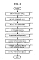
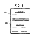
- Step S11 inputs an original image to be processed, such as an original image DO shown in FIG. 4, for example.
- the original image DO is a multivalue image containing confidential information.
- the original image DO may be classified into a foreground section 101 having a plurality of characters, and a background section 102.
- Step S12 obtains embedded data to be embedded into the original image D0.
- the embedded data is embedded into the background section 102 of the original image D0.
- the embedded data contains binary information, which can be expressed by either one of the binary characters 0 and 1, as illustrated in any one of FIGS. 7A, 8A, and 9A. Further, the embedded data is embedded in the form of a plurality of patterns.
- Step S13 selects one or more pattern types of the plurality of patterns based on the information contained in the embedded data.
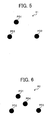
- the information contained in the embedded data can be expressed by either one of the binary characters 0 and 1, two pattern types are selected including a first pattern P1 of FIG. 5 corresponding to the binary character 0, and a second pattern P2 of FIG. 6 corresponding to the binary character 1.
- the first and second patterns P1 and P2 provide different characteristic information, such as the number of dots, density of dots, arrangement of dots, distance between dots, etc. Further, the characteristic information of the first pattern P1 and the characteristic information of the second pattern P2 are partially identical from each other. More specifically, referring to FIG.
- the first pattern P1 contains a first dot PD1, a second dot PD2, and a third dot PD3.
- the second pattern P2 contains a fourth dot PD4 in addition to the first, second, and third dots PD1, PD2, and PD3 that are identical to the dots of the first pattern P1.
- the first pattern P1 and the second patter P2 may be stored for further processing.
- Step S14 of FIG. 3 determines one or more colours to be used for the plurality of patterns based on the information contained in the embedded data.
- the colour of the first pattern P1 and the colour of the first pattern P2 are determined to be partially different from each other. More specifically, the black colour is assigned to each one of the first dot PD1, second dot PD2, and third dot PD3. The gray colour is assigned to the fourth dot PD4.
- the colours of the first pattern P1 and the second pattern P2 may be stored for further processing.
- Step S15 determines an arrangement to be used for the plurality of patterns based on the information contained in the embedded data.
- the arrangement of the plurality of patterns is determined in a corresponding manner with the size of the information contained in the embedded data.
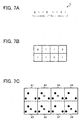
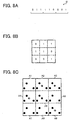
- the arrangement that can form a 4X2 block may be selected as illustrated in FIG. 7B.
- the arrangement that can form a 3X3 block may be selected as illustrated in FIG. 8B.
- the arrangement that can form a 3X3 block may be selected as illustrated in FIG. 9B.
- the arrangement determined by the pattern determinator 13 may be stored for further processing.
- Step S17 embeds the plurality of patterns into the background section 102 of the original image D0 to generate an embedded image.
- Step S17 may be performed by the pattern embedder 14 of FIG. 1 having the functional structure of FIG. 2.
- the colour converter 141 converts the embedded data into colour information of the plurality of patterns, using the colours determined by the pattern determinator 13.
- the pattern determinator 13 determines the colour of the first pattern P1 to be black, and the colour of the second pattern P2 to be partially black and partially gray. If the digit of the information corresponds to the binary character 0, the colour information representing black is obtained. If the digit of the information corresponds to the binary character 1, the colour information representing the combination of black and gray is obtained.
- the arrangement converter 142 converts the embedded data into arrangement information of the plurality of patterns, using the arrangement determined by the pattern determinator 13.
- the pattern determinator 13 determines that the arrangement forming the 4X2 block is used.
- the pattern determinator 13 determines that the arrangement forming the 3X3 block is used.
- the arrangement information of the plurality of patterns is obtained, which specifies the position of each digit of the information or the order of each digit relative to other digits in the information.
- the pattern combiner 145 of FIG. 2 generates the plurality of patterns using the pattern types that are determined by the pattern determinator 13. Further, the pattern combiner 145 causes the plurality of patterns to have the determined colours and the determined arrangement, using the colour information and the arrangement information. The plurality of patterns is then embedded into the background section 102 of the original image DO of FIG. 4.
- the pattern embedder 14 generates eight unit areas A1 to A8 according to the arrangement shown in FIG. 7B. Further, in this example, the binary character 0 of the first embedded data I1 is embedded using the first pattern P1 having the black colour dots. The binary character 1 of the first embedded data I1 is embedded using the second pattern P2 having the black colour dots and the gray colour dot. Accordingly, as illustrated in FIG. 7C, the first patterns P1 are respectively embedded into the unit areas A1, A4, and A7. The second patterns P2 are respectively embedded into the unit areas A2, A3, A5, A6, and A8.
- the pattern embedder 14 generates nine unit areas A1 to A9 according to the arrangement shown in FIG. 8B. Further, in this example, the binary character 0 of the second embedded data I2 is embedded using the first pattern P1 having the black colour dots. The binary character 1 of the second embedded data I2 is embedded using the second pattern P2 having the black colour dots and the gray colour dot. Accordingly, as illustrated in FIG. 8C, the first patterns P1 are respectively embedded into the unit areas A1, A6, A7, and A8. The second patterns P2 are respectively embedded into the unit areas A2, A3, A4, A5, and A9.
- the pattern embedder 14 generates nine unit areas A1 to A9 according to the arrangement shown in FIG. 9B. Further, in this example, the binary character 0 of the third embedded data I3 is embedded using the first pattern P1 having the black colour dots. The binary character 1 of the third embedded data I3 is embedded using the second pattern P2 having the black colour dots and the gray colour dot. Accordingly, as illustrated in FIG. 9C, the first patterns P1 are respectively embedded into the unit areas A1, A2, and A5. The second patterns P2 are respectively embedded into the unit areas A3, A4, A6, A7, A8, and A9.
- the plurality of patterns representing the embedded data is embedded into the entire portion of the background section 102 of the original image D0. To fill in the entire portion of the background section 102, the plurality of patterns is repeatedly embedded. Alternatively, a selected portion of the background section 102 may be embedded with one or more sets of the plurality of patterns.
- Step S18 combines the embedded image and the original image into a processed image.
- the plurality of patterns is embedded into the entire portion of the background section 102 as illustrated in FIG. 10.
- the background section 102 is shown in the dark colour to indicate the presence of the plurality of patterns.
- the processed image D1 of FIG. 10 may look substantially similar to the original image D0 of FIG. 4, at least to the human eye.
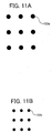
- the size of each dot in the plurality of patterns may affect the appearance of the processed image when the processed image is output. For example, if a dot 103a, shown in FIG. 11A, having the relatively large size is used for the plurality of patterns, the plurality of patterns may be perceptible to the human eye when it is output. In another example, if a dot 103b, shown in FIG. 11B, having the relatively small size is used for the plurality of patterns, the plurality of patterns may not be perceptible to the human eye when it is output.
- Step S19 outputs the processed image, and the operation ends.
- the processed image may be output as a printed document.
- the processed image may be displayed using a display device.
- the processed image may be output via a network.
- FIG. 3 may be performed in various other ways.
- Step S12 may select embedded data according to the user' s preference.
- the user's preference may include any kind of information regarding the characteristic information of the pattern including the colour of the pattern, the size of information contained in the embedded data, the processing time, the easy of detection, etc.
- Step S13 may select any pattern type other than the dot pattern type described above referring to FIG. 5 or 6. For example, a line pattern type or a design pattern type may be used. Further, Step S13 may not be performed when the pattern type is previously determined.
- Step S14 may not be performed when the pattern is previously set to be monochrome or any other colour by default. Further, Steps S13 and S14 may be performed at the same time as the colour is a part of the characteristic information of the plurality of patterns.
- the characteristic information or the relative relationship of the plurality of patterns which may be determined by the pattern determinator 13 in any one of Steps S13, S14, and S15, may be stored in the form of conversion table. Using the conversion table, Step S17 can easily convert embedded data into the plurality of patterns.
- the characteristic information or the relative relationship of the plurality of patterns may be previously defined together with the information contained in the embedded data.
- Step S17 may obtain the colour information or the arrangement information without performing any conversion on the embedded data. Accordingly, the pattern embedder 14 may not require any information from the embedded data obtainer 12.
- Step S18 or S19 may not be performed.
- the embedded image may be stored in a corresponding manner with the original image for later use.
- the embedded data may be embedded into any area other than the background section 102 of the original image DO.
- the embedded data may be embedded into a selected portion of the original image D0 in the form of mark.
- the background section 102 may be further segmented into a message area 102a and a base area 102b.
- the embedded data is embedded into the base area 102b in the form of a plurality of patterns with each pattern having at least one dot 103b shown in FIG. 11B.
- the message area 102a of the background section 102 is embedded with a plurality of patterns with each pattern having at least one dot 103a shown in FIG. 11A.
- the dot 103a of the message area 102a becomes visible to the user, while the dot 103b of the base area 102b remains invisible.
- the embedded data is embedded into the base area 102b in the form of a plurality of patterns with each pattern having at least one dot 103a shown in FIG. 11A.
- the message area 102a of the background section 102 is embedded with a plurality of patterns with each pattern having at least one dot 103b shown in FIG. 11B.
- the dot 103a of the base area 102b becomes visible to the user, while the dot 103b of the message area 102a remains invisible.
- the amount of the embedded data contained in the plurality of patterns can be easily adjusted. Further, the amount of the embedded data can be adjusted by determining a number of pattern types of the plurality of patterns. More specifically, the amount of embedded data I is expressed by the following equation if the binary system is used:
- n n * log 2 N, wherein n corresponds to the number of unit areas that is specified by the arrangement of the plurality of patterns, and N corresponds to the number of pattern types of the plurality of patterns.
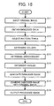
- FIG. 15 operation of generating a processed image, performed by the embedding apparatus 10 of FIG. 1, is explained according to an example embodiment of the present invention.
- the operation of FIG. 15 is substantially similar to the operation of FIG. 3.
- the differences include the addition of Step S16, and the functional structure of the pattern embedder 14 of FIG. 1.
- the pattern embedder 14 of FIG. 1 has the functional structure shown in FIG. 14.
- the pattern embedder 14 includes the colour converter 141, the arrangement converter 142, the pattern combiner 145, an angle converter 143, and a pattern rotator 144.
- Step S16 determines one or more angles to be used for the plurality of patterns based on the information contained in the embedded data.
- each one of the plurality of patterns has two types of angles: one referred to as an absolute angle and the other referred to as a relative angle.
- the absolute angle is an angle of the pattern relative to the upright position of the pattern, i.e., the upright position of the original image.
- the absolute angle can be any value between 0 and 360 degrees.
- a predetermined number of angles may be used, which may be obtained by quantizing the continuous range of angle based on a predetermined unit angle u1.
- the continuous range of angle i.e., 360 degrees is divided by the unit angle u1 of 60 degrees to obtain six levels of the absolute angles.
- the number of levels of the absolute angles, or the number of absolute angles is referred to as a quantization number q.
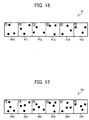
- the absolute angle of the first pattern P1 of FIG. 5 may be expressed by at least one of the six angles illustrated in FIG. 16.
- the first pattern P1 has the absolute angle R10 when it is placed in the upright position.
- the first pattern P1 has the absolute angle R11 when it is placed in the position rotated by one unit angle, i.e., 60 degrees, from the upright position.
- the first pattern P1 has the absolute angle R12 when it is placed in the position rotated by two unit angles, i.e., 120 degrees, from the upright position.
- the first pattern P1 has the absolute angle R13 when it is placed in the position rotated by three unit angles, i.e., 180 degrees, from the upright position.
- the first pattern P1 has the absolute angle R14 when it is placed in the position rotated by four unit angles, i.e., 240 degrees, from the upright position.
- the first pattern P1 has the absolute angle R15 when it is placed in the position rotated by five unit angles, i.e., 300 degrees, from the upright position.
- the arrow shown in FIG. 16 is provided to indicate the orientation of each pattern. Further, in this example, the first pattern P1 is rotated clockwise.
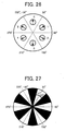
- the absolute angle of the second pattern P2 of FIG. 6 may be expressed by at least one of the six angles illustrated in FIG. 17.
- the second pattern P2 has the absolute angle R20 when it is placed in the upright position.
- the second pattern P2 has the absolute angle R21 when it is placed in the position rotated by one unit angle, i.e., 60 degrees, from the upright position.
- the second pattern P2 has the absolute angle R22 when it is placed in the position rotated by two unit angles, i.e., 120 degrees, from the upright position.
- the second pattern P2 has the absolute angle R23 when it is placed in the position rotated by three unit angles, i.e., 180 degrees from the upright position.
- the second pattern P2 has the absolute angle R24 when it is placed in the position rotated by four unit angles, i.e., 240 degrees from the upright position.
- the second pattern P2 has the absolute angle R25 when it is placed in the position rotated by five unit angles, i.e., 300 degrees from the upright position.
- the arrow shown in FIG. 17 is provided to indicate the orientation of each pattern. Further, in this example, the second pattern P2 is rotated clockwise.
- the relative angle of the first pattern P1 and the second pattern P2 may be specified based on the unit angle u1.
- the relative angle R0 may be specified by setting the difference in absolute angle between the first pattern P1 and the second pattern P2 to be 0 degree.
- the relative angle R1 may be specified by setting the difference in absolute angle between the first pattern P1 and the second pattern P2 to be one unit angle, i.e., 60 degrees.
- the relative angle R2 may be specified by setting the difference in absolute angle between the first pattern P1 and the second pattern P2 to be two unit angles, i.e., 120 degrees.
- the relative angle R3 may be specified by making the difference in absolute angle between the first pattern P1 and the second pattern P2 to be three unit angles, i.e., 180 degrees.
- the relative angle R4 may be specified by setting the difference in absolute angle between the first pattern P1 and the second pattern P2 to be four unit angles, i.e., 240 degrees.
- the relative angle R5 may be specified by setting the difference in absolute angle between the first pattern P1 and the second pattern P2 to be five unit angles, i.e., 300 degrees.
- the absolute angle or the relative angle is determined based on the information contained in the embedded data.
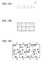
- the first embedded data I1 having 8-bit information "01101101" is obtained.
- the pattern determinator 13 assigns the absolute angle R10 to the binary character 0, and the absolute angle R21 to the binary character 1. Further, the relative angle R1 is assigned to the plurality of patterns.
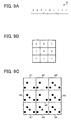
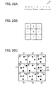
- the fourth embedded data I4 having 9-digit information "022220002" is obtained.
- the pattern determinator 13 assigns the absolute angle R10 to the decimal character 0, and the absolute angle R22 to the decimal character 2. Further, the relative angle R2 is assigned.to the plurality of patterns.
- the fifth embedded data I5 having 9-digit information "551151111" is obtained.
- the pattern determinator 13 assigns the absolute angle R15 to the decimal character 5, and the absolute angle R21 to the decimal character 1. Further, the relative angle R4 is assigned to the plurality of patterns.
- Step S17 embeds the plurality of patterns into the background section 102 of the original image D0 to generate an embedded image.
- Step S17 may be performed by the pattern embedder 14 having the functional structure of FIG. 14.
- the colour converter 141 converts the embedded data into colour information of the pluratliy of patterns using the colours determined by the pattern determinator 13, in a substantially similar manner as described referring to FIGS. 2 and 3.
- the arrangement converter 142 converts the embedded data into arrangement information of the plurality of patterns, using the arrangement determined by the pattern determinator 13.
- the pattern determinator 13 determines that the arrangement forming the 4X2 block is used.
- the pattern determinator 13 determines that the arrangement forming the 3X3 block is used.
- the arrangement information of the plurality of patterns is obtained, which specifies the position of each digit of the information or the order of each digit relative to the other digits in the information.
- the angle converter 143 converts the embedded data into angle information of the pluratliy of patterns, using the angles determined by the pattern determinator 13.
- the pattern determinator 13 determines that the absolute angles of the first pattern P1 and the second pattern P2 to be R10 and R21, respectively. Further, the pattern determinator 13 determines that the relative angle between the first pattern P1 and the second pattern P2 to be R1. Based on this angle information, the pattern rotator 144 obtains the first pattern P1 having the absolute degree R10 and the second pattern P2 having the absolute degree R21.
- the pattern determinator 13 determines that the absolute angles of the first pattern P1 and the second pattern P2 to be R10 and R22, respectively. Further, the pattern determinator 13 determines that the relative angle between the first pattern P1 and the second pattern P2 to be R2. Based on this angle information, the pattern rotator 144 obtains the first pattern P1 having the absolute degree R10 and the second pattern P2 having the absolute degree R22.
- the pattern determinator 13 determines that the absolute angles of the first pattern P1 and the second pattern P2 to be R15 and R21, respectively. Further, the pattern determinator 13 determines that the relative angle between the first pattern P1 and the second pattern P2 to be R4. Based on this angle information, the pattern rotator 144 obtains the first pattern P1 having the absolute degree R15 and the second pattern P2 having the absolute degree R21.
- the pattern combiner 145 generates the plurality of patterns using the pattern types that are determined by the pattern determinator 13. Further, the pattern combiner 145 causes the pluraltiy of patterns to have the determined colours, the determined arrangement, and the determined angles, using the colour information, arrangement information, and angle information. The plurality of patterns is then embedded into the background section 102 of the original image D0 of FIG. 4.
- the pattern embedder 14 generates eight unit areas A1 to A8 according to the arrangement shown in FIG. 18B. Further, in this example, the binary character 0 of the first embedded data I1 is embedded using the first pattern P1 having the absolute angle R10. The binary character 1 of the first embedded data I1 is embedded using the second pattern P2 having the absolute angle R21. Further, the first pattern P1 and the second pattern P2 are embedded so as to have the relative angle R1.
- the pattern embedder 14 generates nine unit areas A1 to A9 according to the arrangement shown in FIG. 19B. Further, in this example, the decimal character 0 of the fourth embedded data I4 is embedded using the first pattern P1 having the absolute degree R10. The decimal character 2 of the fourth embedded data 14 is embedded using the second pattern P2 having the absolute degree R22. Further, the first pattern P1 and the second pattern P2 are embedded so as to have the relative angle R2.
- the pattern embedder 14 generates nine unit areas A1 to A9 according to the arrangement shown in FIG. 20B. Further, in this example, the decimal character 5 of the fifth embedded data 15 is embedded using the first pattern P1 having the absolute degree R15. The decimal character 1 of the fifth embedded data 15 is embedded using the second pattern P2 having the absolute degree R21. Further, the first pattern P1 and the second pattern P2 are embedded so as to have the relative angle R4.'
- Step S15 may not be performed.
- the arrangement converter 142 of FIG. 14 may not be provided.
- Step S16 at least one of the absolute angle and the relative angle may be determined to generate the angle information.
- the amount of the embedded data contained in the plurality of patterns can be easily adjusted. More specifically, the amount of embedded data I is expressed by the following equation if the binary system is used:
- the extracting apparatus 20 is capable of extracting embedded data from an original image, when the original image has been embedded with the embedded data.
- the extracting apparatus 20 includes an original image input 21, a colour detector 22, a pattern detector 23, and an embedded data obtainer 24.
- the original image input 21 inputs an original image to be processed.
- the original image is presumed to include an embedded area that has been embedded with embedded data in the form of a plurality of patterns. Further, the original image may be input in various ways, for example, as described above referring to the original image input 11 of FIG. 1.
- the colour detector 22 extracts one or more colour components from the original image, and converts the original image into a binary image having the extracted colour components.
- the colour detector 22 when the plurality of patterns is embedded with the green colour component and the original image is input with the RGB (red, green, blue) format, the colour detector 22 extracts the green colour component from the original image, and generates a binary image having the green colour component.
- the colour detector 22 when the plurality of patterns is embedded with the cyan and magenta colour components and the original image is input with the RGB format, the colour detector 22 first converts the original image from the RGB format to the CMY (cyan, magenta, yellow) format. The colour detector 22 then extracts the cyan and magenta colour components from the original image to generate a binary image having the cyan and magenta colour components.
- the pattern detector 23 detects the plurality of patterns from the embedded area of the original image. In this example, the pattern detector 23 detects the plurality of patterns from the binary image generated by the colour detector 22 using information regarding the plurality of patterns. In one example, the pattern detector 23 detects the plurality of patterns using the pattern matching method. In another example, the pattern detector 23 detects the plurality of patterns using characteristic information of the plurality of patterns.
- the embedded data obtainer 24 analyzes the plurality of patterns to obtain the embedded data of the original image. In one example, the embedded data obtainer 24 analyzes the characteristic information of the plurality of patterns, such as the pattern types of the plurality of patterns. In another example, the embedded data obtainer 24 analyzes the relative relationship of the plurality of patterns, such as the arrangement or the angles of the plurality of patterns.
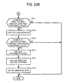
- the pattern detector 23 of FIG. 21 has the functional structure shown in FIG. 22.
- the pattern detector 23 includes a pattern extractor 231, a pattern counter 232, a first pattern detector 233, and a second pattern detector 234.
- Step S101 inputs an original image to be processed, such as the processed image D1 of FIG. 10, for example.
- the processed image D1 has the background section 102, to which embedded data is embedded in the form of a plurality of patterns. Further, in this example, the processed image D1 is input with the RGB format.
- the original image input 21 may determine whether the processed image D1 is in the upright position. If the processed image D1 is not in the upright position, the processed image D1 is rotated to be in the upright position.
- Step S102 extracts one or more colour components from the background section 102 of the processed image D1.
- colour component information of the plurality of patterns which indicates the colour components used for the plurality of patterns, is stored in a memory of the extracting apparatus 20 of FIG. 1.
- the colour component information may be provided from the user, if such information is known to the user.
- the colour component information may be obtained from the processed image D1, if such information has been embedded in the processed image D1 together with the plurality of patterns.
- the plurality of patterns is presumed to be embedded with the cyan and magenta colour components.
- the colour detector 22 converts the background section 102 of the processed image D1 from the RGB format to the CMY format.
- the colour detector 22 then extracts the cyan and magenta components from the background section 102.
- the colour detector 22 generates a binary image by assigning the value 1 to the cyan and magenta components and the value 0 to the yellow component of the background section 102.
- the pattern detector 23 detects the plurality of patterns using characteristic information of the pluratliy of patterns, as described below referring to Steps S103 to S114. More specifically, in this example, the pattern detector 23 having the functional structure shown in FIG. 22 detects the first pattern P1 of FIG. 5 and the second pattern P2 of FIG. 6.
- the pattern extractor 231 divides the binary image into a plurality of unit areas, and selects one of the plurality of unit areas for further processing.
- each unit area is embedded with the corresponding one of the plurality of patterns.
- the characteristic information of the pattern is obtained.
- the characteristic information may include any kind of information obtainable from the pattern, such as the number of dots, density of dots, distance between dots, etc.
- Step S104 the first pattern detector 233 determines whether the selected pattern matches the first pattern P1 by comparing the characteristic information of the selected pattern with the characteristic information of the first pattern P1.
- the characteristic information of the first pattern P1 may be stored in the first pattern detector 233. If the characteristic information of the selected pattern is substantially similar to the characteristic information of the first pattern P1 ("YES" in Step S104), the operation proceeds to Step S106 to increase a detected number of the first pattern P1 by one. If the characteristic information of the selected pattern is different from the characteristic information of the first pattern P1 ("NO" in Step S104), the operation proceeds to Step S107.
- Step S107 the second pattern detector 234 of FIG. 22 determines whether the selected pattern matches the second pattern P2 by comparing the characteristic information of the selected pattern with the characteristic information of the second pattern P2.
- the characteristic information of the second pattern P2 may be stored in the second pattern detector 234. If the characteristic information of the selected pattern is substantially similar to the characteristic information of the second pattern P2 ("YES" in Step S107), the operation proceeds to Step S109 to increase a detected number of the second pattern P2 by one. If the characteristic information of the selected pattern is different from the characteristic information of the second pattern P2 ("NO" in Step S109), the operation proceeds-to Step S110.
- Step S110 the pattern extractor 231 determines whether all unit areas of the binary image are processed. If all unit areas have been processed ("YES" in Step S110), the operation proceeds to Step S111 of FIG. 23B. If all unit areas have not been processed ("NO" in Step S110), the operation returns to Step S103 to select another unit area to determine whether the selected pattern matches either one of the first pattern P1 and the second pattern P2.
- the first pattern detector 233 of FIG. 23 determines whether the detected number of the first pattern P1 is greater than a first reference value Ref1.
- the first reference value Ref1 is previously stored in the first pattern detector 233. If the detected number is greater than the first reference value Ref1 ("YES" in Step S111), the operation proceeds to step S112 to determine that the first pattern P1 is detected and output information regarding the detected first pattern P1 to the embedded data obtainer 24. If the detected number is equal to or less than the first reference value Ref1 ("NO" in Step S111), the operation ends to return an error message indicating that the first pattern P1 is not detected.
- Step S113 the second pattern detector 234 of FIG. 22 determines whether the detected number of the second pattern P2 is greater than a second reference value Ref2.
- the second reference value Ref2 is stored in the second pattern detector 234. If the detected number is greater than the second reference value Ref2 ("YES" in Step S113), the operation proceeds to Step S114 to determine that the second pattern P2 is detected and output information regarding the detected second pattern P2 to the embedded data obtainer 24. If the detected number is equal to or less than the second reference value Ref2 ("NO" in Step S113), the operation ends to return an error message indicating the second pattern P2 is not detected.
- the embedded data obtainer 24 of FIG. 22 analyzes the first pattern P1 and the second pattern P2, which are detected by the pattern detector 23.
- the first pattern P1 and the second pattern P2 are analyzed using the arrangement information of the plurality of patterns, which may be stored in a memory of the extracting apparatus 20 of FIG. 1.
- the arrangement information may be provided from the user, if such information is known to the user.
- the arrangement information may be obtained from the processed image D1, if such information has been embedded in the processed image D1 together with the plurality of patterns.
- the embedded data obtainer 24 extracts a set of the first pattern P1 and the second pattern P2, which can form the 4X2 block, from the detected first pattern P1 and the second pattern P2.
- the embedded data obtainer 24 extracts a set of the first pattern P1 and the second pattern P2, which can form the 3X3 block, from the detected first pattern P1 and the second pattern P2.
- the embedded data obtainer 24 obtains the embedded data of the processed image D1.
- the embedded data obtainer 24 converts the extracted set of the first pattern P1 and the second pattern P2 into a set of the binary character 0 and the binary character 1.
- FIGS. 23A and 23B may be performed in various other ways.
- Step S102 of extracting one or more colour components may not be performed, when the black colour component is used for the plurality of patterns and the original image is input as a binary image.
- the binary image may be provided directly from the original image input 21 to the pattern detector 23. Accordingly, the colour detector 22 may not be provided.
- the pattern detector 23 of FIG. 21 may first determine whether the original image is embedded with embedded data. For example, one-bit information indicating whether the embedded data has been embedded may be previously embedded in the original image together with the plurality of patterns.
- the pattern counter 232 of FIG. 22 may count the number of a plurality of patterns that matches either one of the first pattern P1 and the second pattern P2, which can be detected by the pattern extractor 231. As shown in FIGS. 5 and 6, any pattern that matches either one of the first pattern P1 and the second pattern P2 ("the detected pattern") can be extracted using the characteristic information common to the first pattern P1 and the second pattern P2, i.e., the characteristic information of the first, second, and third dots PD1, PD2, and PD3.
- the pattern counter 232 determines that at least one of the first pattern P1 and the second pattern P2 is detected, and provides information regarding the detected pattern to the first pattern detector 233 or the second pattern detector 234. If the number of the detected patterns is equal to or less than the third reference value, the pattern counter 232 determines that none of the first pattern P1 and the second pattern P2 is detected, and sends an error message indicating that no pattern is detected.
- the third reference value may be stored in a memory of the extracting apparatus 20.
- the pluratliy of patterns may be detected from a selected portion of the background section 102. In such case, the number of unit areas to be processed may be reduced.
- Steps S103 to S114 of detecting the first pattern P1 and the second pattern P2 may be performed in various other ways.
- the first pattern P1 or the second pattern P2 may be detecting using the pattern matching method.
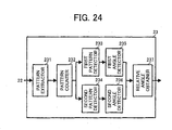
- the pattern detector 23 of FIG. 21 has the functional structure shown in FIG. 24.
- the pattern detector 23 includes a first angle detector 235, a second angle detector 236, and a relative angle obtainer 237, in addition to the pattern extractor 231, the pattern counter 232, the first pattern detector 233, and the second pattern detector 234 of FIG. 22.
- Step S201 inputs an original image to be processed, such as the processed image D1 of FIG. 10, for example.
- the processed image D1 has the background section 102, to which embedded data is embedded in the form of a plurality of patterns. Further, in this example, the processed image D1 is input with the RGB format.
- the original image input 21 may determine whether the processed image D1 is in the upright position. If the processed image D1 is not in the upright position, the processed image D1 is rotated to be in the upright position.
- Step S202 extracts one or more colour components from the background section 102 of the processed image D1 in a substantially similar manner as described referring to Step S102 of FIG. 23A.
- the colour detector 22 generates a binary image by assigning the value 1 to the cyan and magenta components and the value 0 to the yellow component of the background section 102 of the processed image D1.
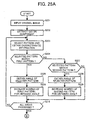
- the pattern detector 23 detects the plurality of patterns using characteristic information and relative relationship of the plurality of patterns, as described below referring to Step S203 to S214. More specifically, in this example, the pattern detector 23 having the functional structure shown in FIG. 24 detects a relative angle of the first pattern P1 of FIG. 5 and the second pattern P2 of FIG. 6.
- the pattern extractor 231 divides the binary image into a plurality of unit areas, and obtains a selected pattern from one of the plurality of unit areas in a substantially similar manner as described referring to Step S103 of FIG. 23A.
- the pattern extractor 231 further obtains characteristic information of the selected pattern.
- the first pattern detector 233 determines whether the selected pattern matches the first pattern P1 by comparing the characteristic information of the selected pattern with the characteristic information of the first pattern P1.
- the characteristic information of the first pattern P1 is stored for each one of the absolute angles obtainable from the first pattern P1. As described above referring to FIG. 15, the number of absolute angles is determined based on the unit angle u1. If the unit angle u1 is determined to be 60 degrees, the characteristic information of the first pattern P1 is stored for each one of the six absolute angles R10, R11, R12, R13, R14, and R15 as shown in FIG. 16.
- Step S204 If the characteristic information of the selected pattern is substantially similar to the characteristic information of the first pattern P1 having at least one of the absolute angles R10 to R15 ("YES" in Step S204), the operation proceeds to Step S205. If the characteristic information of the selected pattern is not similar to the characteristic information of the first pattern P1 having at least one of the absolute angles R10 to R15 ("NO" in Step S204), the operation proceeds to Step S207.
- the first angle detector 235 obtains the absolute angle of the selected pattern, i.e., the first pattern P1. Since the first pattern P1 has six levels of absolute angles, the detected angle of the selected pattern is presumed to correspond to at least one of the six absolute angles R10 to R15 shown in FIG. 16. More specifically, in this example, the first angle detector 235 determines whether the value of detected angle belongs to at least one of a plurality of ranges, with each range corresponding to each level of the absolute angles. For example, as illustrated in FIG. 26, if the selected pattern has the detected angle that falls in the range from 0 to 30 degrees or from 330 to 360 degrees (-30 to 30 degrees), the first angle detector 235 determines that the selected pattern has the absolute angle R10. Similarly, if the selected pattern has the detected angle that falls in the range from 30 to 90 degrees, the first angle detector 235 determines that the selected pattern has the absolute angle R11.
- Step S206 the first angle detector 235 increases, by one, a detected number of the first pattern P1 for the absolute angle obtained in the previous step. For example, if the absolute angle R10 is obtained in Step S206, the first angle detector 235 increases the detected number of the first pattern P1 having the absolute angle R10. In this manner, the detected number of the first pattern P1 is obtained for each one of the absolute angles R10 to R15.
- the second pattern detector 234 determines whether the selected pattern matches the second' pattern P2 by comparing the characteristic information of the selected pattern with the characteristic information of the second pattern P2.
- the characteristic information of the second pattern P2 is stored for each one of the absolute angles obtainable from the second pattern P2. As described above referring to FIG. 15, the number of absolute angles is determined based on the unit angle u1. If the unit angle u1 is determined to be 60 degrees, the characteristic information of the second pattern P2 is stored for each one of the six absolute angles R20, R21, R22, R23, R24, and R25 as shown in FIG. 17.
- Step S207 If the characteristic information of the selected pattern is substantially similar to the characteristic information of the second pattern P2 having at least one of the absolute angles R20 to R25 ("YES" in Step S207), the operation proceeds to Step S208. If the characteristic information of the selected pattern is not similar to the characteristic information of the second pattern P2 having at least one of the absolute angles R20 to R25 ("NO" in Step S207), the operation proceeds to Step S210.
- Step S208 the second angle detector 236 obtains the absolute angle of the selected pattern, i.e., the second pattern P2, in a substantially similar manner as described above referring to Step S205.
- Step S209 the second angle detector 236 increases, by one, a detected number of the second pattern P2 for the absolute angle obtained in the previous step. In this manner, the detected number of the second pattern P2 is obtained for each one of the absolute angles R20 to R25.
- Step S210 the pattern extractor 231 determines whether all unit areas of the binary image are processed. If all unit areas have been processed ("YES" in Step S210), the operation proceeds to Step S211 of FIG. 25B. If all unit areas have not been processed ("NO" in Step S210), the operation returns to Step S203 to select another unit area to determine whether the selected pattern matches either one of the first pattern P1 and the pattern P2.
- the first angle detector 235 determines whether the peak is detected among the detected numbers that are obtained in Step S206 for each one of the absolute angles of the first pattern P1.
- the peak refers to the highest detected number
- a peak angle refers to the absolute angle having the highest detected number. If the peak is detected ("YES" in Step S211), the operation proceeds to Step S212 to determine that the peak angle is detected for the first pattern P1, and output information regarding the peak angle to the relative angle obtainer 237 of FIG. 24. If the peak is not detected ("NO" in Step S211), the operation ends to send an error message indicating that the angle of the first pattern P1 is undetectable.
- Step S213 the second angle detector 236 determines whether the peak is detected among the detected numbers that are obtained in Step S209 for each one of the absolute angles of the second pattern P2, in a substantially similar manner as described referring to Step S211. If the peak is detected ("YES" in Step S213), the operation proceeds to Step S214 to determine that the peak angle is detected for the second pattern P2, and output information regarding the peak angle to the relative angle obtainer 237 of FIG. 24. If the peak is not detected ("NO" in Step S213), the operation ends to send an error message indicating that the angle of the second pattern P2 is undetectable.
- the relative angle obtainer 237 analyzes the peak angle ("the first peak angle") of the first pattern P1 and the peak angle ("the second peak angle") of the second pattern P2 to obtain a relative angle between the first pattern P1 and the second pattern P2.
- the relative angle can be obtained by calculating the difference between the first peak angle and the second peak angle.
- the embedded data obtainer 24 of FIG. 24 obtains the embedded data of the processed image D1.
- the embedded data obtainer 24 converts the relative angle into the decimal character of the embedded data.
- the embedded data obtainer 24 converts any one of the first peak angle and the second peak angle into the decimal character of the embedded data.
- the relative angle Rr of the first pattern P1 and the second pattern P2 may be obtained using the following equation:
- Rr
- Ral corresponds to the absolute angle of the first pattern obtainable from the first peak angle
- Ra2 corresponds to the absolute angle of the second pattern obtainable from the second peak angle
- u2 corresponds to the unit angle used for extracting.
- the Mod360/u2 corresponds to the remainder obtained by dividing 360 degrees by the unit angle u2 degrees.
- the unit angle u2 for extracting is set to be equal to the unit angle u1 for embedding.
- FIGS. 25A and 25B may be performed in various other ways as described above referring to FIGS. 23A and 23B.
- the original image input 21 may not determine whether the processed image D1 is in the upright position, if the embedded data can be obtained only from the relative angle of the plurality of patterns. In such case, the absolute angle of the first pattern P1 or the second pattern P2 may not be obtained.
- Steps S203 to S215 of detecting the relative angle of the first pattern P1 and the second pattern P2 may be performed in various other ways'.
- the unit angle u1 or the'quantization number q, which may be used for detecting the relative angle may be previously determined based on various parameters.
- any one of the detected absolute angle or the detected relative angle of the plurality of patterns may be classified into one of the ranges determined by the unit angle u1, each range corresponding to each level of the absolute angles determined during the embedding process.
- the detected absolute angle or the detected relative angle (collectively, referred to as "the detected angle") may not be extracted with high accuracy due to various factors.
- the original image may be distorted during scanning due to the scanner capacity.
- the original document may be distorted during printing due to the printer capacity. Accordingly, the absolute angle or the relative angle may not be obtained with high accuracy.
- the value of the detected angle can be used for further processing only when the value falls in the range indicated by the black colour.
- the value of the detected angle may not be accurately extracted when the value falls in the range indicated by the white colour.
- the black colour range has the amount of degrees substantially equal to the amount of degrees of the white colour range. This indicates that the probability of accurately extracting the detected angle is 50 percent. This probability may be further reduced when the fluctuation range of the detected angle increases.
- the relative angle of the first pattern P1 and the second pattern P2 is presumed to be equal to the relative angle R2 as shown in FIG. 26.
- the detected absolute angle of the first pattern P1 fluctuates in the range of 30 degrees
- the detected absolute angle of the first pattern P1 may be inaccurately determined to be the absolute angle R11 when the detected absolute angle falls in the black colour range.
- the detected absolute angle of the second pattern P2 fluctuates in the range of 30 degrees
- the detected absolute angle of the second pattern P2 may be inaccurately determined to be the absolute angle R23 when the detected absolute angle falls in the black colour range.
- the relative angle of the first pattern P1 and the second pattern P2 may vary from R1 to R3.
- FIG. 28 illustrates another example case in which the unit angle is set to be 30 degrees. Accordingly, the continuous range of angle is divided into twelve levels of absolute angles. Further, in this example, the value of the detected angle fluctuates in the range of 15 degrees from -7.5 degrees to +7.5 degrees. In such case, the value of the detected angle can be used for further processing only when the value falls in the range indicated by the black colour. From the comparison between the black colour range and the white colour range, the probability of accurately extracting the detected angle is determined to be 50 percent.
- any one of the unit angle u1 for embedding, the quantization number q, a unit angle u2 for extracting, the range used for extracting may be specified.
- the value of unit angle u2 for extracting is specified to be equal to or greater than twice the fluctuation range f of the detected angle (referred to as the "rule 1"), as indicated by the following equation: u 2 ⁇ 2 ⁇ f .
- the fluctuation range of detected angle can be obtained by the empirical rule using a scanner or a printer, for example.
- the rule 2. may be described as the situation in which the unit angle u1 for embedding is specified to be equal to twice the value of unit angle u2 for extracting.
- the detected angle is presumed to fluctuate in the range of 30 degrees from -15 degrees to +15 degrees.
- the unit angle u2 for extracting is determined to be 60 degrees. Further, the unit angle u1 for embedding is determined to be 120 degrees according to the second rule. Since the quantization number q is three, a plurality of patterns each having three absolute angles may be obtained during the embedding process. Further, the number of relative angles is limited to three. In the examples described below, the plurality of patterns can be classified into a third pattern P3 and a fourth pattern P4.
- the third pattern P3 may have the absolute angle R30 corresponding to the upright position of the third pattern P3; the absolute angle R32 corresponding to the orientation rotated by one unit angle, i.e., 120 degrees from the upright position; and the absolute angle R34 corresponding to the orientation rotated by two unit angles, i.e., 240 degrees from the upright position. At least one of the absolute angles R30, R32 and R34 may be selected when embedding the third pattern P3, for example, depending on the information contained in the embedded data. Similarly, as illustrated in FIG.
- the fourth pattern P4 may have the absolute angle R40 corresponding to the upright position; the absolute angle R42 corresponding to the orientation rotated by one unit angle, i.e., 120 degrees from the upright position; and the absolute angle R44 corresponding to the orientation rotated by two unit angles, i.e., 240 degrees from the upright position. At least one of the absolute angles R40, R42 and R44 may be selected when embedding the fourth pattern P4, for example, depending on the information contained in the embedded data. Using any combination of the third pattern P3 and the fourth pattern P4, the relative angle may be determined to be at least one of the relative angle R1 corresponding'to 0 degree, the relative angle R2 corresponding to 120 degrees, and the relative angle R3 corresponding to 240 degrees.
- the third pattern P3 may have the absolute angle R31 corresponding to the orientation rotated by 60 degrees from the upright position; the absolute angle R33 corresponding to the orientation rotated by one unit angle, i.e., 120 degrees from the absolute angle R31; and the absolute angle R35 corresponding to the orientation rotated by two unit angles, i.e., 240 degrees from the absolute angle R31. At least one of the absolute angles R31, R33 and R35 may be selected when embedding the third pattern P3, for example, depending on the information contained in the embedded data. Similarly, as illustrated in FIG.
- the fourth pattern P4 may have the absolute angle R41 corresponding to the orientation rotated by 60 degrees from the upright position; the absolute angle R43 corresponding to the orientation rotated by one unit angle, i.e., 120 degrees from the absolute angle R41; and the absolute angle R45 corresponding to the orientation rotated by two unit angles, i.e., 240 degrees from the absolute angle R41. At least one of the absolute angles R41, R43 and R45 may be selected when embedding the fourth pattern P4, for example, depending on the information contained in the embedded data.
- the relative angle may be determined to be at least one of the relative angle R1 corresponding to 0 degree, the relative angle R2 corresponding to 120 degrees, and the relative angle R3 corresponding to 240 degrees.
- FIGS. 33 to 35 operation of determining the unit angle u2 for extracting is explained according to an example embodiment of the present invention.
- an original image is presumed to be embedded with the third pattern P3 having the absolute angle R30 and the fourth pattern P4 having the absolute angle R42.
- the relative angle of the third pattern P3 and the fourth pattern P4 is presumed to be R2, i.e., 120 degrees.
- the fluctuation range of detected angle is set to be equal to 30 degrees.
- the unit angle u2 for extracting is determined to be equal to or greater than 60 degrees.
- the continuous angle of degree is divided by 60 degrees to obtain six ranges as illustrated in FIG. 26.
- the detected angle can be then classified into one of the six ranges in a substantially similar manner as described above referring to FIG. 26.
- the absolute angle R30 of 0 degree may be inaccurately detected as the detected absolute angle of 30 degrees (indicated by al), and the absolute angle R42 of 120 degrees may be inaccurately detected as the detected absolute angle of 150 degrees (indicated by a2).
- the absolute angle R30 or the absolute angle R42 may not be accurately detected.
- the relative angle of the third pattern P3 and the fourth pattern P4 may not be accurately detected.
- the number of ranges that has been generated based on the unit angle u2 for extracting may be reduced by combining two ranges that are adjacent from each other into one range.
- the combination of two ranges may be determined based on the detected angle. For example, as illustrated in any one of FIGS. 33 and 34, a first range to which the detected angle belongs, and a second range adjacent to the first range, may be combined into one range.
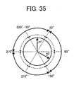
- the combination of two ranges may be previously defined by default, for example, as illustrated in FIG. 35.
- the combination of two ranges may be determined based on the angle information indicating the absolute or relative angles of the plurality of patterns.
- the range from -30 degrees to 30 degrees and the range from 30 degrees to 90 degrees are combined into one range from -30 degrees to 90 degrees.
- the range from 90 degrees to 150 degrees and the range from 150 degrees to 210 degrees are combined into one range from 90 degrees to 210 degrees.
- the range from 210 degrees to 270 degrees and the range from 270 degrees to 330 degrees are combined into one range from 210 degrees to 330 degrees.
- the range from 30 degrees to 90 degrees and the range from 90 degrees to 150 degrees are combined into the range from 30 degrees to 150 degrees.
- the range from 150 degrees to 210 degrees and the range from 210 degrees to 270 degrees are combined into the range from 150 degrees to 270 degrees.
- the range from 270 degrees to 330 degrees and the range from -30 degrees to 30 degrees are combined into the range from 270 degrees to 30 degrees.
- the absolute angle or relative angle of the plurality of patterns can be obtained with high accuracy.
- the detected absolute angle of 30 degrees falls in the range from -30 degrees to 90 degrees
- the detected absolute angle is determined to be the absolute angle R30 of 0 degree.
- the detected absolute angle of 150 degrees falls in the range from 90 degrees to 210 degrees
- the detected absolute angle is determined to be the absolute angle R42 of 120 degrees.
- the relative angle of the third pattern P3 and the fourth pattern P4 is determined to be R1.
- the absolute angle R30 of 0 degree is accurately detected (indicated by al), and the absolute angle R42 of 120 degrees is accurately detected.
- the absolute angles of the third pattern P3 and the fourth pattern P4 can be respectively extracted with high accuracy. Further, the relative angle of the third pattern P3 and the fourth pattern P4 can be accurately extracted.
- the value of unit angle u2 for extracting may not be necessarily equal to or greater than twice the fluctuation range of the detected angle, as the rule 1 states. More specifically, the value of unit angle u2 for extracting can be specified to be greater than the fluctuation range f of the detected angle (referred to as the "rule 3"), as expressed by the following equation: u 2 > f .
- the unit angle u2 for extracting can be set to be substantially equal to 30 degrees, when the fluctuation range of the detected angle is 30 degrees. Further, the unit angle u1 for embedding can be set to 60 degrees. If the rule 3 is applied instead of the rule 1, the amount of information that can be embedded as the embedded data may increase.
- the unit angle u2 for extracting may be further broken down into one or more minimum unit angles s.
- the minimum unit angle s corresponds to the unit angle having the minimum value obtainable by quantizing the continuous range of angle. Since the range can be broken down into one or more unit angles u2 and each one of the unit angles u2 can be broken down into one or more minimum unit angles s, the range can be broken down into one or more minimum unit angles s.
- the rule 3 may be applied by obtaining the smallest value of the number x of minimum unit angles s that can satisfy the equation:
- the rule 2 may be applied by obtaining the largest value of the quantization number q that can satisfy the equation:
- the absolute angle or the relative angle can be expressed as a set of ⁇ s*x*2*0, s*x*2*1, ..., s*x*2* (q-1) ⁇ .
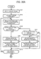
- FIGS. 36A and 36B operation of obtaining embedded data from an original image, performed by the extracting apparatus of FIG. 21, is explained according to an example embodiment of the present invention.
- the operation of FIGS. 36A and 36B is substantially similar to the operation of FIGS. 25A and 25B.
- the differences include the addition of Step S311 and Step S313 shown in FIG. 36B.
- the first angle detector 235 determines the classification of the first peak angle, using any one of the above-described rules.
- the six ranges shown in FIG. 26 may be reclassified into three ranges as described above referring to any one of FIGS. 33 to 35. According to these three ranges, the detected numbers obtained for the six angles are converted to the detected numbers for the three angles. From the converted detected numbers, the peak angle having the highest detected number is obtained for further processing.
- Step S313 the second angle detector 236 determines the classification of the second peak angle, using any one.of the above-described rules, in a substantially similar manner as described referring to Step S311.
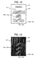
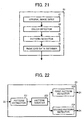
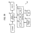
- any one of the above-described embedding apparatus 10 of FIG. 1, the extracting apparatus 20 of FIG. 21, and other example embodiments of the present invention may be implemented in various ways, for example, as an image forming apparatus 300 shown in FIG. 37, an image forming system 400 shown in FIG. 39, or an image processing apparatus shown in FIG. 40.
- the image forming apparatus 300 of FIG. 37 may be implemented by a multifunctional apparatus capable of performing a plurality of functions including the functions of scanning, printing, copying, etc.
- the image forming apparatus 300 includes a scanner 301, image processor 302, printer 303, controller 304, and operation panel 305.
- the scanner 301 includes any kind of device capable of reading an original document into an original image to be processed.
- the image processor 302 includes any kind of device capable of applying various image processing to the original image.
- the printer 303 includes any kind of device capable of outputting the original image, such as a printer or a plotter.
- the operation panel 305 functions as a user interface.
- the operation panel 305 at least includes an input device allowing a user to input data such as a plurality of keys, and a display device displaying data to the user such as a liquid crystal display.
- the controller 304 controls at least one of the scanner 301, image processor 302, and printer 303 according to an instruction received from the operation panel 205.
- the controller 304 includes a central processing unit (CPU) 3041, read only memory (ROM) 3042, and random access memory (RAM) 3043.
- CPU central processing unit
- ROM read only memory
- RAM random access memory
- the image forming apparatus 300 may function as the extracting apparatus 20 of FIG. 21.
- the image processor 302 may have the structure shown in FIG. 38.
- the image processor 302 includes a filter 3021, scaler 3022, gamma processor 3033, halftone processor 3034, selector 3035, colour converter 3036, pattern detector 3037, and an embedded data obtainer 3038.
- the controller 304 of FIG. 37 is incorporated into the image processor 302.
- the scanner 301 may function as the original image input 21 of FIG. 21.
- the scanner 301 reads an original document into an original image to be processed, according to an instruction received from the user via the operation panel 305.
- the filter 3021 may apply preprocessing to the original image before providing the original image to the colour converter 3036.
- the colour converter 3036 may function as the colour detector 22 of FIG. 21, which converts the original image into a binary image using one or more colour components.
- the pattern detector 3037 may function as the pattern detector 23 of FIG. 21, which detects a plurality of patterns from the original image or the binary image.
- the embedded data obtainer 3038 may function as the embedded data obtainer 24 of FIG. 21, which converts the plurality of patterns into embedded data.
- the embedded data is output to the selector 3035. Based on the embedded data, the selector 3035 controls operation of the printer 303. Any one of the scaler 3022, gamma processor 3033, and halftone processor 3034 may apply to various image processing to the original image.
- the printer 303 operates according to an instruction received from the selector 3035.
- the printer 303 when the embedded data is not obtained by the selector 3035, the printer 303 is caused to print out the original image as the printed original document.
- the printer 303 when the embedded data is obtained by the selector 3035, the printer 303 is caused to cancel printing of the original image.
- the printer 303 when the embedded data is obtained by the selector 3035, the printer 303 is caused to conceal the information contained in the original image, for example, by making the plurality of patterns visible to the user.
- the printer 303 when the embedded data is obtained by the selector 3035, the printer 303 is caused to notify the user that the original image is copy guarded, for example, by making a pattern or a mark visible to the user.
- the image forming apparatus 300 may function as the embedding apparatus 10 of FIG. 1.
- the structure of the image processor 302 may differ from the structure shown in FIG. 38.
- the pattern detector 3037 and the embedded data obtainer 3038 may not be provided.
- a pattern determinator functioning as the pattern determinator 13 of FIG. 1 and a pattern embedder functioning as the pattern embedder 14 of FIG. 1 may be additionally provided.
- the scanner 301 may function as the original image input 11 of FIG. 1.
- the scanner 301 reads an original document into an original image to be processed, according to an instruction received from the user via the operation panel 305.
- the operation panel 305 may function as the embedded data obtainer 12 by allowing the user to input embedded data or any parameters regarding the embedded data.
- the memory incorporated in the image processor 302, such as the ROM 3042 may function as the embedded data obtainer 12 by storing information regarding the embedded data.
- a storage device such as a hard disk drive (HDD) may be provided.
- the printer 303 may function as the processed image output 15, which outputs the processed image as a printed document.
- the operation panel 305 may function as the processed image by displaying the processed image using the display device.
- the image forming system 400 includes a scanner 401, image processor 402, printer 403, controller 404, operation panel 405, and HDD 406.
- the scanner 401 includes any kind of'device capable of reading an original document into an original image to be processed.
- the image processor 402 includes any kind of device capable of applying various image processing to the original image.
- the printer 403 includes any kind of device capable of outputting the original image, such as a printer or a plotter.
- the controller 404 controls operation of the image forming system 400.
- the operation panel 305 functions as a user interface.
- the HDD 406 includes any kind of storage capable of storing a large amount of data.
- the HDD 406 may store an image processing program of the present invention.
- the CPU 4041 loads the image processing program onto a ROM 4042, and causes the image forming system 400 to function as the embedding apparatus 10 of FIG. 1 or the extracting apparatus 20 of FIG. 21.
- the image processing apparatus 500 includes a CPU 501, ROM 502, RAM 503, hard disk drive (HDD) 504, disc drive 505, and an interface (I/F) 506, which are connected via a bus 507.
- the image processing apparatus 500 may be implemented by a personal computer, for example.
- the CPU 501 includes any kind of processor capable of controlling operation of the image processing apparatus 500.
- the ROM 502 includes any kind of involatile memory, such as BIOS, for example.
- the HDD 504 includes any kind of storage capable of storing a large amount of data.
- the disc drive 505 includes any kind of device capable of reading data from a removable disc 508.
- the I/F 506 includes any kind of device capable of functioning as a user interface, such as an input device including a mouse or a keyboard, a display device, etc.
- the I/F 506 may further function as a network interface, which connects the image processing apparatus 500 to a network such as a local area network (LAN) or the Internet.
- LAN local area network
- the image processing program of the present invention may be installed on the HDD 204 from the removable disc 508 storing the image processing program.
- the image processing program may be further loaded onto the ROM 502 upon activation of the CPU 501.
- the image processing program may be downloaded from any other device or apparatus via the network, through the interface 506. Further, the image processing program may be uploaded from the image processing apparatus 500 to any other device or apparatus through the network.
- any one of the above-described and other methods of the example embodiments of the present invention may be embodied in the form of a computer program stored in any kind of storage medium.
- storage mediums include, but are not limited to, flexible disk, hard disk, optical discs, magneto-optical discs, magnetic tapes, involatile memory cards, ROM (read-only-memory), etc.
- any one of the above-described and other methods of the example embodiments of the present invention may be implemented by ASIC, prepared by interconnecting an appropriate network of conventional component circuits or by a combination thereof with one or more.conventional general purpose microprocessors and/or signal processors programmed accordingly.
Abstract
Description
- The following disclosure relates generally to an apparatus, method, system, computer program and product, each capable of embedding data into a document or extracting embedded data from a document.
- Recent image processing apparatuses have a function of prohibiting output of a copy guarded document. The copy guarded document corresponds to any kind of document prohibited from being reproduced, such as a monetary document or a confidential document. Once an input document is recognized as the copy guarded document, for example, based on a pattern or mark detected in the input document, output of the input document may be prohibited. Alternatively, information contained in the input document may be changed or concealed when the input document is output, when the input document is recognized as the copy guarded document.
- However, the amount of data that can be contained in the pattern or mark of the copy guarded document is usually limited. In the example case described in the
U.S. Patent Application Publication No. 2005078331, published on April 14, 2005 , the amount of data that can be contained in one pattern is limited to one-bit. - In light of the above-described and other problems, example embodiments of the present invention provide an apparatus, method, system, computer program and product, each capable of embedding data into a document or extracting embedded data from a document. The data to be embedded, i.e., the embedded data, may contain more than one bit of information.
- In one example, a processed image, which functions as a copy guarded image, may be generated from an original image by embedding embedded data into the original image. The embedded data is embedded into an embedded area of the original image in the form of a plurality of patterns. The plurality of patterns has a relative relationship, which is determined based on the embedded data.
- In another example, embedded data may be extracted from an original image, if the original image is recognized as a processed image, i.e., a copy guarded image. A plurality of patterns having a relative relationship may be detected in the original image. The embedded data may be obtained by analyzing the relative relationship of the plurality of patterns.
- A more complete appreciation of the disclosure and many of the attendant advantages thereof will be readily obtained as the same becomes better understood by reference to the following detailed description of example embodiments when considered in connection with the accompanying drawings, in which:
- FIG. 1 is a schematic block diagram illustrating the functional structure of an embedding apparatus according to an example embodiment of the present invention;
- FIG. 2 is a schematic block diagram illustrating the functional structure of a pattern embedder shown in FIG. 1 according to an example embodiment of the present invention;
- FIG. 3 is a flowchart illustrating operation of generating a processed image, performed by the embedding apparatus of FIG. 1, according to an example embodiment of the present invention;
- FIG. 4 is an illustration of an example original image to be processed by the embedding apparatus of FIG. 1;
- FIG. 5 is an illustration of a first pattern to be embedded by the embedding apparatus of FIG. 1 according to an example embodiment of the present invention;
- FIG. 6 is an illustration of a second pattern to be embedded by the embedding apparatus of FIG. 1 according to an example embodiment of the present invention;
- FIG. 7A is an illustration of first embedded data to be embedded into an embedded area of the original image of FIG. 4 according to an example embodiment of the present invention;
- FIG. 7B is an illustration of an example arrangement determined by the embedding apparatus of FIG. 1;
- FIG. 7C is an illustration of a plurality of patterns embedded into the embedded area of the original image of FIG. 4, based on the first embedded data of FIG. 7A;
- FIG. 8A is an illustration of second embedded data to be embedded into an embedded area of the original image of FIG. 4 according to an example embodiment of the present invention;
- FIG. 8B is an illustration of an example arrangement determined by the embedding apparatus of FIG. 1;
- FIG. 8C is an illustration of a plurality of patterns embedded into the embedded area of the original image of FIG. 4, based on the second embedded data of FIG. 8R;
- FIG. 9A is an illustration of third embedded data to be embedded into an embedded area of the original image of FIG. 4 according to an example embodiment of the present invention;
- FIG. 9B is an illustration of an example arrangement determined by the embedding apparatus of FIG. 1;
- FIG. 9C is an illustration of a plurality of patterns embedded into the embedded area of the original image of FIG. 4, based on the third embedded data of FIG. 9A;
- FIG. 10 is an illustration of an example processed image generated from the example original image of FIG. 4;
- FIG. 11A is an illustration of an example first type dot contained in the processed document image of FIG. 10;
- FIG. 11B is an illustration of an example second type dot contained in the processed document image of FIG. 10;
- FIG. 12 is an illustration of a processed document obtained by outputting the example processed image shown in FIG. 10 according to an example embodiment of the present invention;
- FIG. 13 is an illustration of a processed document obtained by outputting the example processed image shown in FIG. 10 according to an example embodiment of the present invention;
- FIG. 14 is a schematic block diagram illustrating the functional structure of a pattern embedder shown in FIG. 1 according to an example embodiment of the present invention;
- FIG. 15 is a flowchart illustrating operation of generating a processed image, performed by the image processing apparatus of FIG. 1, according to an example embodiment of the present invention;
- FIG. 16 is an illustration of a plurality of first patterns each having a different absolute angle according to an example embodiment of the present invention;
- FIG. 17 is an illustration of a plurality of second patterns each having a different absolute angle according to an example embodiment of the present invention;
- FIG. 18A is an illustration of the first embedded data to be embedded into an embedded area of the original image of FIG. 4 according to an example embodiment of the present invention;
- FIG. 18B is an illustration of an example arrangement determined by the embedding apparatus of FIG. 1;
- FIG. 18C is an illustration of a plurality of patterns embedded into the embedded area of the original image of FIG. 4, based on the first embedded data of FIG. 18A;
- FIG. 19A is an illustration of fourth embedded data to be embedded into an embedded area of the original image of FIG. 4 according to an example embodiment of the present invention;
- FIG. 19B is an illustration of an example arrangement determined by the embedding apparatus of FIG. 1;
- FIG. 19C is an illustration of a plurality of patterns embedded into the embedded area of the original image of FIG. 4, based on the fourth embedded data of FIG. 19A;
- FIG. 20A is an illustration of fifth embedded data to be embedded into an embedded area of the original image of FIG. 4 according to an example embodiment of the present invention;
- FIG. 20B is an illustration of an example arrangement determined by the embedding apparatus of FIG. 1;
- FIG. 20C is an illustration of a plurality of patterns embedded into the embedded area of the original image of FIG. 4, based on the fifth embedded data of FIG. 20A;
- FIG. 21 is a schematic block diagram illustrating the functional structure of an extracting apparatus according to an example embodiment of the present invention;
- FIG. 22 is a schematic block diagram illustrating the functional structure of a pattern detector shown in FIG. 21 according to an example embodiment of the present invention;
- FIGS. 23A and 23B are flowcharts illustrating operation of obtaining embedded data from an original image, preformed by the extracting apparatus of FIG. 21, according to an example embodiment of the present invention;
- FIG. 24 is a schematic block diagram illustrating the functional structure of a pattern detector shown in FIG. 21 according to an example embodiment of the present invention;
- FIGS. 25A and 25B are flowcharts illustrating operation of obtaining embedded data from an original image, performed by the extracting apparatus of FIG. 21, according to an example embodiment of the present invention;
- FIG. 26 is an illustration for explaining operation of obtaining an angle of a plurality of patterns according to an example embodiment of the present invention;
- FIG. 27 is an illustration for explaining operation of obtaining an angle of a plurality of patterns according to an example embodiment of the present invention;
- FIG. 28 is an illustration for explaining operation of obtaining an angle of a plurality of patterns according to an example embodiment of the present invention;
- FIG. 29 is an illustration of a plurality of third patterns each having a different absolute angle according to an example embodiment of the present invention;
- FIG. 30 is an illustration of a plurality of fourth patterns each having a different absolute angle according to an example embodiment of the present invention;
- FIG. 31 is an illustration of a plurality of third patterns each having a different absolute angle according to an example embodiment of the present invention;
- FIG. 32 is an illustration of a plurality of fourth patterns each having a different absolute angle according to an example embodiment of the present invention;
- FIG. 33 is an illustration for explaining operation of obtaining an angle of a plurality of patterns according to an example embodiment of the present invention;
- FIG. 34 is an illustration for explaining operation of obtaining an angle of a plurality of patterns according to an example embodiment of the present invention;
- FIG. 35 is an illustration for explaining operation of obtaining an angle of a plurality of patterns according to an example embodiment of the present invention;
- FIG. 36A and 36B are flowcharts illustrating operation of obtaining embedded data from an original image, preformed by the extracting apparatus of FIG. 21, according to an example embodiment of the present invention;
- FIG. 37 is a schematic block diagram illustrating the structure of an image forming apparatus according to an example embodiment of the present invention;
- FIG. 38 is a schematic block diagram illustrating the structure of an image processor shown in FIG. 37 according to an example embodiment of the present invention;
- FIG. 39 is a schematic block diagram illustrating the structure of an image forming system according to an example embodiment of the present invention; and
- FIG. 40 is a schematic block diagram illustrating the structure of an image processing apparatus according to an example embodiment of the present invention.
- In describing the example embodiments illustrated in the drawings, specific terminology is employed for clarity. However, the disclosure of this, patent specification is not intended to be limited to the specific terminology selected and it is to be understood that each specific element includes all technical equivalents that operate in a similar manner. Referring now to the drawings, wherein like reference numerals designate identical or corresponding parts throughout the several views, FIG. 1 illustrates an embedding
apparatus 10 according to an example embodiment of the present invention. The embeddingapparatus 10 is capable of embedding data into an original image. As shown in FIG. 1, the embeddingapparatus 10 includes anoriginal image input 11, an embeddeddata obtainer 12, apattern determinator 13, apattern embedder 14, and a processedimage output 15. - The
original image input 11 inputs an original image to be processed. In one example, theoriginal image input 11 may obtain the original image from the outside, such as a storage device or medium connected to the embeddingapparatus 10. In another example, theoriginal image input 11 may receive an original document, and convert it into the original image using a scanner. In another example, theoriginal image input 11 may read out the original image from a memory of the embeddingapparatus 10. - The embedded
data obtainer 12 obtains embedded data, which is to be embedded into an embedded area of the original image. In this example, the embedded data may be previously determined by default. Alternatively, the embedded data may be determined according to the user' s preference. The embedded data contains information, which can be expressed by a predetermined number of digits, for example, as described below referring to any one of FIGS. 7A, 8A, 9A, 18A, 19A, and 20A. Further, in this example, the embedded data is to be embedded in the form of a plurality of patterns. - The pattern determinator 13 determines one or more types to be used for the plurality of patterns, based on the information contained in the embedded data. For example, if the embedded data contains information that can be expressed by either one of the
binary characters pattern determinator 13 may select a first pattern type corresponding to thebinary character 0, and a second pattern type corresponding to thebinary character 1, from a plurality of pattern types available for use. In another example, if the embedded data contains information that can be expressed by at least one of thedecimal characters 0 to 7, thepattern determinator 13 may select first to eighth pattern types respectively corresponding to thedecimal characters 0 to 7, from the plurality of pattern types available for use. - Once the pattern types are determined for the plurality of patterns, the
pattern determinator 13 may further determine one or more colours to be used for the plurality of patterns based on the information contained in the embedded data. For example, a specific colour may be assigned to each one of the pattern types of the plurality of patterns. Alternatively, the black colour may be assigned to each one of the pattern types by default. - The pattern determinator.13 may further determine a relative relationship to be used for the plurality of patterns based on the information contained in the embedded data.
- In one example, the
pattern determinator 13 may determine an arrangement to be used for the plurality of patterns based on the information contained in the embedded data. For example, if the information contained in the embedded data can be expressed by eight digits, thepattern determinator 13 may determine an arrangement of the 8-digit information, which specifies the order or the position of each digit of the 8-digit information. - In another example, the
pattern determinator 13 may determine one or more angles to be used for the plurality of patterns based on the information contained in the embedded data. In this example, the angles of the plurality of patterns can be classified into two types: one type referred to as an absolute angle; and the other type referred to as a relative angle. - If the information contained in the embedded data can be expressed by either one of the
binary characters pattern determinator 13 may determine a first absolute angle of the pattern corresponding to thebinary character 0, and a second absolute angle of the pattern corresponding to thebinary character 1. Alternatively, the information contained in the embedded data may be expressed by a relative angle of at least two patterns, which indicates the relationship of the absolute angles of the at least two patterns. - Any one of the pattern type, colour, and relative relationship to be used for the plurality of patterns, which are determined by the
pattern determinator 13, may be stored for further processing. - The pattern embedder 14 embeds the plurality of patterns into the embedded area of the original image to generate an embedded image. For example, the
pattern embedder 14 may generate the plurality of patterns using the pattern type, colour, and relative relationship that are determined by thepattern determinator 13. Accordingly, the plurality of patterns of the embedded image has the pattern type, colour, and relative relationship, which are determined based on the embedded data. - The processed
image output 15 combines the embedded image and the original image into a processed image. The processed image may be further output as a printed document. Alternatively, the processed image may be sent as electronic data. - Referring now to FIG. 3, operation of generating a processed image, performed by the embedding
apparatus 10 of FIG. 1, is explained according to an example embodiment of the present invention. Specifically, in this example, thepattern embedder 14 of FIG. 1 has the functional structure shown in FIG. 2. Referring to FIG. 2, thepattern embedder 14 includes acolour converter 141, anarrangement converter 142, and apattern combiner 145. - Referring to FIG. 3, Step S11 inputs an original image to be processed, such as an original image DO shown in FIG. 4, for example. The original image DO is a multivalue image containing confidential information. As shown in FIG. 4, the original image DO may be classified into a
foreground section 101 having a plurality of characters, and abackground section 102. - Step S12 obtains embedded data to be embedded into the original image D0. In this example, the embedded data is embedded into the
background section 102 of the original image D0. Further, in this example, the embedded data contains binary information, which can be expressed by either one of thebinary characters - Step S13 selects one or more pattern types of the plurality of patterns based on the information contained in the embedded data. In this example, since the information contained in the embedded data can be expressed by either one of the
binary characters binary character 0, and a second pattern P2 of FIG. 6 corresponding to thebinary character 1. The first and second patterns P1 and P2 provide different characteristic information, such as the number of dots, density of dots, arrangement of dots, distance between dots, etc. Further, the characteristic information of the first pattern P1 and the characteristic information of the second pattern P2 are partially identical from each other. More specifically, referring to FIG. 5, the first pattern P1 contains a first dot PD1, a second dot PD2, and a third dot PD3. Referring to FIG. 6, the second pattern P2 contains a fourth dot PD4 in addition to the first, second, and third dots PD1, PD2, and PD3 that are identical to the dots of the first pattern P1. The first pattern P1 and the second patter P2 may be stored for further processing. - Step S14 of FIG. 3 determines one or more colours to be used for the plurality of patterns based on the information contained in the embedded data. In this example, the colour of the first pattern P1 and the colour of the first pattern P2 are determined to be partially different from each other. More specifically, the black colour is assigned to each one of the first dot PD1, second dot PD2, and third dot PD3. The gray colour is assigned to the fourth dot PD4. The colours of the first pattern P1 and the second pattern P2 may be stored for further processing.
- Step S15 determines an arrangement to be used for the plurality of patterns based on the information contained in the embedded data. In this example, the arrangement of the plurality of patterns is determined in a corresponding manner with the size of the information contained in the embedded data.
- In one example, if the first embedded data I1 of FIG. 7A having 8-bit information "01101101" is obtained, the arrangement that can form a 4X2 block may be selected as illustrated in FIG. 7B. In another example, if the second embedded data I2 of FIG. 8A having 9-bit information "011110001" is obtained, the arrangement that can form a 3X3 block may be selected as illustrated in FIG. 8B. Similarly, if the third embedded data I3 of FIG. 9A having 9-bit information "001101111" is obtained, the arrangement that can form a 3X3 block may be selected as illustrated in FIG. 9B. The arrangement determined by the
pattern determinator 13 may be stored for further processing. - Referring back to FIG. 3, Step S17 embeds the plurality of patterns into the
background section 102 of the original image D0 to generate an embedded image. Step S17 may be performed by thepattern embedder 14 of FIG. 1 having the functional structure of FIG. 2. - Referring to FIG. 2, the
colour converter 141 converts the embedded data into colour information of the plurality of patterns, using the colours determined by thepattern determinator 13. In this example, thepattern determinator 13 determines the colour of the first pattern P1 to be black, and the colour of the second pattern P2 to be partially black and partially gray. If the digit of the information corresponds to thebinary character 0, the colour information representing black is obtained. If the digit of the information corresponds to thebinary character 1, the colour information representing the combination of black and gray is obtained. - The
arrangement converter 142 converts the embedded data into arrangement information of the plurality of patterns, using the arrangement determined by thepattern determinator 13. In one example shown in FIG. 7B, thepattern determinator 13 determines that the arrangement forming the 4X2 block is used. In another example shown in FIG. 8B or 9B, thepattern determinator 13 determines that the arrangement forming the 3X3 block is used. According to the arrangement shown in any one of FIGS. 7B, 8B, and 9B, for example, the arrangement information of the plurality of patterns is obtained, which specifies the position of each digit of the information or the order of each digit relative to other digits in the information. - The
pattern combiner 145 of FIG. 2 generates the plurality of patterns using the pattern types that are determined by thepattern determinator 13. Further, thepattern combiner 145 causes the plurality of patterns to have the determined colours and the determined arrangement, using the colour information and the arrangement information. The plurality of patterns is then embedded into thebackground section 102 of the original image DO of FIG. 4. - In the example case illustrated in FIG. 7C, the
pattern embedder 14 generates eight unit areas A1 to A8 according to the arrangement shown in FIG. 7B. Further, in this example, thebinary character 0 of the first embedded data I1 is embedded using the first pattern P1 having the black colour dots. Thebinary character 1 of the first embedded data I1 is embedded using the second pattern P2 having the black colour dots and the gray colour dot. Accordingly, as illustrated in FIG. 7C, the first patterns P1 are respectively embedded into the unit areas A1, A4, and A7. The second patterns P2 are respectively embedded into the unit areas A2, A3, A5, A6, and A8. - In the example case illustrated in FIG. 8C, the
pattern embedder 14 generates nine unit areas A1 to A9 according to the arrangement shown in FIG. 8B. Further, in this example, thebinary character 0 of the second embedded data I2 is embedded using the first pattern P1 having the black colour dots. Thebinary character 1 of the second embedded data I2 is embedded using the second pattern P2 having the black colour dots and the gray colour dot. Accordingly, as illustrated in FIG. 8C, the first patterns P1 are respectively embedded into the unit areas A1, A6, A7, and A8. The second patterns P2 are respectively embedded into the unit areas A2, A3, A4, A5, and A9. - In the example case illustrated in FIG. 9C, the
pattern embedder 14 generates nine unit areas A1 to A9 according to the arrangement shown in FIG. 9B. Further, in this example, thebinary character 0 of the third embedded data I3 is embedded using the first pattern P1 having the black colour dots. Thebinary character 1 of the third embedded data I3 is embedded using the second pattern P2 having the black colour dots and the gray colour dot. Accordingly, as illustrated in FIG. 9C, the first patterns P1 are respectively embedded into the unit areas A1, A2, and A5. The second patterns P2 are respectively embedded into the unit areas A3, A4, A6, A7, A8, and A9. - Further, in this example, the plurality of patterns representing the embedded data is embedded into the entire portion of the
background section 102 of the original image D0. To fill in the entire portion of thebackground section 102, the plurality of patterns is repeatedly embedded. Alternatively, a selected portion of thebackground section 102 may be embedded with one or more sets of the plurality of patterns. - Referring back to FIG. 3, Step S18 combines the embedded image and the original image into a processed image. As described above, the plurality of patterns is embedded into the entire portion of the
background section 102 as illustrated in FIG. 10. In FIG. 10, thebackground section 102 is shown in the dark colour to indicate the presence of the plurality of patterns. However, the processed image D1 of FIG. 10 may look substantially similar to the original image D0 of FIG. 4, at least to the human eye. - In this example, the size of each dot in the plurality of patterns may affect the appearance of the processed image when the processed image is output. For example, if a
dot 103a, shown in FIG. 11A, having the relatively large size is used for the plurality of patterns, the plurality of patterns may be perceptible to the human eye when it is output. In another example, if adot 103b, shown in FIG. 11B, having the relatively small size is used for the plurality of patterns, the plurality of patterns may not be perceptible to the human eye when it is output. - Referring back to FIG. 3, Step S19 outputs the processed image, and the operation ends. In one example, the processed image may be output as a printed document. In another example, the processed image may be displayed using a display device. In another example, the processed image may be output via a network.
- The operation of FIG. 3 may be performed in various other ways.
- In one example, as described above, Step S12 may select embedded data according to the user' s preference. The user's preference may include any kind of information regarding the characteristic information of the pattern including the colour of the pattern, the size of information contained in the embedded data, the processing time, the easy of detection, etc.
- In another example, Step S13 may select any pattern type other than the dot pattern type described above referring to FIG. 5 or 6. For example, a line pattern type or a design pattern type may be used. Further, Step S13 may not be performed when the pattern type is previously determined.
- In another example, Step S14 may not be performed when the pattern is previously set to be monochrome or any other colour by default. Further, Steps S13 and S14 may be performed at the same time as the colour is a part of the characteristic information of the plurality of patterns.
- In another example, the characteristic information or the relative relationship of the plurality of patterns, which may be determined by the
pattern determinator 13 in any one of Steps S13, S14, and S15, may be stored in the form of conversion table. Using the conversion table, Step S17 can easily convert embedded data into the plurality of patterns. - Alternatively, the characteristic information or the relative relationship of the plurality of patterns may be previously defined together with the information contained in the embedded data. In such case, Step S17 may obtain the colour information or the arrangement information without performing any conversion on the embedded data. Accordingly, the
pattern embedder 14 may not require any information from the embeddeddata obtainer 12. - In another example, Step S18 or S19 may not be performed. In such case, the embedded image may be stored in a corresponding manner with the original image for later use.
- In another example, the embedded data may be embedded into any area other than the
background section 102 of the original image DO. For example, the embedded data may be embedded into a selected portion of the original image D0 in the form of mark. Alternatively, as illustrated in any one of FIGS. 12 and 13, thebackground section 102 may be further segmented into amessage area 102a and abase area 102b. - Referring to the processed image D1 shown in FIG. 12, the embedded data is embedded into the
base area 102b in the form of a plurality of patterns with each pattern having at least onedot 103b shown in FIG. 11B. Themessage area 102a of thebackground section 102 is embedded with a plurality of patterns with each pattern having at least onedot 103a shown in FIG. 11A. When the processed image D1 of FIG. 12 is output, thedot 103a of themessage area 102a becomes visible to the user, while thedot 103b of thebase area 102b remains invisible. - Referring to the processed image D1 shown in FIG. 13, the embedded data is embedded into the
base area 102b in the form of a plurality of patterns with each pattern having at least onedot 103a shown in FIG. 11A. Themessage area 102a of thebackground section 102 is embedded with a plurality of patterns with each pattern having at least onedot 103b shown in FIG. 11B. When the processed image D1 of FIG. 13 is output, thedot 103a of thebase area 102b becomes visible to the user, while thedot 103b of themessage area 102a remains invisible. - As described above, by determining the arrangement of the plurality of patterns based on the embedded data, the amount of the embedded data contained in the plurality of patterns can be easily adjusted. Further, the amount of the embedded data can be adjusted by determining a number of pattern types of the plurality of patterns. More specifically, the amount of embedded data I is expressed by the following equation if the binary system is used:
- I = n * log2N, wherein n corresponds to the number of unit areas that is specified by the arrangement of the plurality of patterns, and N corresponds to the number of pattern types of the plurality of patterns.
- Referring now to FIG. 15, operation of generating a processed image, performed by the embedding
apparatus 10 of FIG. 1, is explained according to an example embodiment of the present invention. The operation of FIG. 15 is substantially similar to the operation of FIG. 3. The differences include the addition of Step S16, and the functional structure of thepattern embedder 14 of FIG. 1. - Specifically, in this example, the
pattern embedder 14 of FIG. 1 has the functional structure shown in FIG. 14. Referring to FIG. 14, thepattern embedder 14 includes thecolour converter 141, thearrangement converter 142, thepattern combiner 145, anangle converter 143, and apattern rotator 144. - Referring to FIG. 15, Step S16 determines one or more angles to be used for the plurality of patterns based on the information contained in the embedded data. In this example, each one of the plurality of patterns has two types of angles: one referred to as an absolute angle and the other referred to as a relative angle.
- The absolute angle is an angle of the pattern relative to the upright position of the pattern, i.e., the upright position of the original image. The absolute angle can be any value between 0 and 360 degrees. However, a predetermined number of angles may be used, which may be obtained by quantizing the continuous range of angle based on a predetermined unit angle u1. In this example, the continuous range of angle, i.e., 360 degrees is divided by the unit angle u1 of 60 degrees to obtain six levels of the absolute angles. In this example, the number of levels of the absolute angles, or the number of absolute angles, is referred to as a quantization number q.
- More specifically, the absolute angle of the first pattern P1 of FIG. 5 may be expressed by at least one of the six angles illustrated in FIG. 16. Referring to FIG. 16, the first pattern P1 has the absolute angle R10 when it is placed in the upright position. The first pattern P1 has the absolute angle R11 when it is placed in the position rotated by one unit angle, i.e., 60 degrees, from the upright position. The first pattern P1 has the absolute angle R12 when it is placed in the position rotated by two unit angles, i.e., 120 degrees, from the upright position. The first pattern P1 has the absolute angle R13 when it is placed in the position rotated by three unit angles, i.e., 180 degrees, from the upright position. The first pattern P1 has the absolute angle R14 when it is placed in the position rotated by four unit angles, i.e., 240 degrees, from the upright position. The first pattern P1 has the absolute angle R15 when it is placed in the position rotated by five unit angles, i.e., 300 degrees, from the upright position. The arrow shown in FIG. 16 is provided to indicate the orientation of each pattern. Further, in this example, the first pattern P1 is rotated clockwise.
- Similarly, in this example, the absolute angle of the second pattern P2 of FIG. 6 may be expressed by at least one of the six angles illustrated in FIG. 17. Referring to FIG. 17, the second pattern P2 has the absolute angle R20 when it is placed in the upright position. The second pattern P2 has the absolute angle R21 when it is placed in the position rotated by one unit angle, i.e., 60 degrees, from the upright position. The second pattern P2 has the absolute angle R22 when it is placed in the position rotated by two unit angles, i.e., 120 degrees, from the upright position. The second pattern P2 has the absolute angle R23 when it is placed in the position rotated by three unit angles, i.e., 180 degrees from the upright position. The second pattern P2 has the absolute angle R24 when it is placed in the position rotated by four unit angles, i.e., 240 degrees from the upright position. The second pattern P2 has the absolute angle R25 when it is placed in the position rotated by five unit angles, i.e., 300 degrees from the upright position. The arrow shown in FIG. 17 is provided to indicate the orientation of each pattern. Further, in this example, the second pattern P2 is rotated clockwise.
- Further, in this example, the relative angle of the first pattern P1 and the second pattern P2 may be specified based on the unit angle u1. For'example, the relative angle R0 may be specified by setting the difference in absolute angle between the first pattern P1 and the second pattern P2 to be 0 degree. Similarly, the relative angle R1 may be specified by setting the difference in absolute angle between the first pattern P1 and the second pattern P2 to be one unit angle, i.e., 60 degrees. Similarly, the relative angle R2 may be specified by setting the difference in absolute angle between the first pattern P1 and the second pattern P2 to be two unit angles, i.e., 120 degrees. Similarly, the relative angle R3 may be specified by making the difference in absolute angle between the first pattern P1 and the second pattern P2 to be three unit angles, i.e., 180 degrees. Similarly, the relative angle R4 may be specified by setting the difference in absolute angle between the first pattern P1 and the second pattern P2 to be four unit angles, i.e., 240 degrees. Similarly, the relative angle R5 may be specified by setting the difference in absolute angle between the first pattern P1 and the second pattern P2 to be five unit angles, i.e., 300 degrees.
- Further, in this example, the absolute angle or the relative angle is determined based on the information contained in the embedded data.
- In the example case illustrated in FIG. 18A, the first embedded data I1 having 8-bit information "01101101" is obtained. The pattern determinator 13 assigns the absolute angle R10 to the
binary character 0, and the absolute angle R21 to thebinary character 1. Further, the relative angle R1 is assigned to the plurality of patterns. - In the example case illustrated in FIG. 19A, the fourth embedded data I4 having 9-digit information "022220002" is obtained. The pattern determinator 13 assigns the absolute angle R10 to the
decimal character 0, and the absolute angle R22 to thedecimal character 2. Further, the relative angle R2 is assigned.to the plurality of patterns. - In the example case illustrated in FIG. 20A, the fifth embedded data I5 having 9-digit information "551151111" is obtained. The pattern determinator 13 assigns the absolute angle R15 to the
decimal character 5, and the absolute angle R21 to thedecimal character 1. Further, the relative angle R4 is assigned to the plurality of patterns. - Referring back to FIG. 15, Step S17 embeds the plurality of patterns into the
background section 102 of the original image D0 to generate an embedded image. In this example, Step S17 may be performed by thepattern embedder 14 having the functional structure of FIG. 14. - Referring to FIG. 14, the
colour converter 141 converts the embedded data into colour information of the pluratliy of patterns using the colours determined by thepattern determinator 13, in a substantially similar manner as described referring to FIGS. 2 and 3. - The
arrangement converter 142 converts the embedded data into arrangement information of the plurality of patterns, using the arrangement determined by thepattern determinator 13. In one example shown in FIG. 18B, thepattern determinator 13 determines that the arrangement forming the 4X2 block is used. In another example shown in FIG. 19B or 20B, thepattern determinator 13 determines that the arrangement forming the 3X3 block is used. According to the arrangement shown in any one of FIGS. 18B, 19B, and 20B, for example, the arrangement information of the plurality of patterns is obtained, which specifies the position of each digit of the information or the order of each digit relative to the other digits in the information. - The
angle converter 143 converts the embedded data into angle information of the pluratliy of patterns, using the angles determined by thepattern determinator 13. - In one example shown in FIG. 18C, the
pattern determinator 13 determines that the absolute angles of the first pattern P1 and the second pattern P2 to be R10 and R21, respectively. Further, thepattern determinator 13 determines that the relative angle between the first pattern P1 and the second pattern P2 to be R1. Based on this angle information, thepattern rotator 144 obtains the first pattern P1 having the absolute degree R10 and the second pattern P2 having the absolute degree R21. - In another example shown in FIG. 19C, the
pattern determinator 13 determines that the absolute angles of the first pattern P1 and the second pattern P2 to be R10 and R22, respectively. Further, thepattern determinator 13 determines that the relative angle between the first pattern P1 and the second pattern P2 to be R2. Based on this angle information, thepattern rotator 144 obtains the first pattern P1 having the absolute degree R10 and the second pattern P2 having the absolute degree R22. - In another example shown in FIG. 20C, the
pattern determinator 13 determines that the absolute angles of the first pattern P1 and the second pattern P2 to be R15 and R21, respectively. Further, thepattern determinator 13 determines that the relative angle between the first pattern P1 and the second pattern P2 to be R4. Based on this angle information, thepattern rotator 144 obtains the first pattern P1 having the absolute degree R15 and the second pattern P2 having the absolute degree R21. - Referring back to FIG. 14, the
pattern combiner 145 generates the plurality of patterns using the pattern types that are determined by thepattern determinator 13.
Further, thepattern combiner 145 causes the pluraltiy of patterns to have the determined colours, the determined arrangement, and the determined angles, using the colour information, arrangement information, and angle information. The plurality of patterns is then embedded into thebackground section 102 of the original image D0 of FIG. 4. - In the example case illustrated in FIG. 18C, the
pattern embedder 14 generates eight unit areas A1 to A8 according to the arrangement shown in FIG. 18B. Further, in this example, thebinary character 0 of the first embedded data I1 is embedded using the first pattern P1 having the absolute angle R10. Thebinary character 1 of the first embedded data I1 is embedded using the second pattern P2 having the absolute angle R21. Further, the first pattern P1 and the second pattern P2 are embedded so as to have the relative angle R1. - In the example case illustrated in FIG. 19C, the
pattern embedder 14 generates nine unit areas A1 to A9 according to the arrangement shown in FIG. 19B. Further, in this example, thedecimal character 0 of the fourth embedded data I4 is embedded using the first pattern P1 having the absolute degree R10. Thedecimal character 2 of the fourth embeddeddata 14 is embedded using the second pattern P2 having the absolute degree R22. Further, the first pattern P1 and the second pattern P2 are embedded so as to have the relative angle R2. - In the example case illustrated in FIG. 20C, the
pattern embedder 14 generates nine unit areas A1 to A9 according to the arrangement shown in FIG. 20B. Further, in this example, thedecimal character 5 of the fifth embeddeddata 15 is embedded using the first pattern P1 having the absolute degree R15. Thedecimal character 1 of the fifth embeddeddata 15 is embedded using the second pattern P2 having the absolute degree R21. Further, the first pattern P1 and the second pattern P2 are embedded so as to have the relative angle R4.' - The operation shown in FIG. 15 may be performed in various other ways, for example, as described above referring to FIG. 3. Further, Step S15 may not be performed. In such case, the
arrangement converter 142 of FIG. 14 may not be provided. Furthermore, in Step S16, at least one of the absolute angle and the relative angle may be determined to generate the angle information. - As described above, by determining the angles of the plurality of patterns based on the embedded data, the amount of the embedded data contained in the plurality of patterns can be easily adjusted. More specifically, the amount of embedded data I is expressed by the following equation if the binary system is used:
- I = Ra * log2Rr, wherein Ra corresponds to the number of levels of absolute angles obtained by quantizing the continuous range of angle using the unit angle u1, and Rr corresponds to the number of levels of relative angles determined by the unit angle u1. Since both the absolute angle Ra and the relative angle Rr depends on the unit angle u1 or the quantization number q = 360/ul, the above equation can be simplified using the quantization number q to the following equation:

- Referring now to FIG. 21, an extracting
apparatus 20 is explained according to an example embodiment of the present invention. The extractingapparatus 20 is capable of extracting embedded data from an original image, when the original image has been embedded with the embedded data. As shown in FIG. 21, the extractingapparatus 20 includes anoriginal image input 21, acolour detector 22, apattern detector 23, and an embeddeddata obtainer 24. - The
original image input 21 inputs an original image to be processed. In this example, the original image is presumed to include an embedded area that has been embedded with embedded data in the form of a plurality of patterns. Further, the original image may be input in various ways, for example, as described above referring to theoriginal image input 11 of FIG. 1. - The
colour detector 22 extracts one or more colour components from the original image, and converts the original image into a binary image having the extracted colour components. - In one example, when the plurality of patterns is embedded with the green colour component and the original image is input with the RGB (red, green, blue) format, the
colour detector 22 extracts the green colour component from the original image, and generates a binary image having the green colour component. In another example, when the plurality of patterns is embedded with the cyan and magenta colour components and the original image is input with the RGB format, thecolour detector 22 first converts the original image from the RGB format to the CMY (cyan, magenta, yellow) format. Thecolour detector 22 then extracts the cyan and magenta colour components from the original image to generate a binary image having the cyan and magenta colour components. - The
pattern detector 23 detects the plurality of patterns from the embedded area of the original image. In this example, thepattern detector 23 detects the plurality of patterns from the binary image generated by thecolour detector 22 using information regarding the plurality of patterns. In one example, thepattern detector 23 detects the plurality of patterns using the pattern matching method. In another example, thepattern detector 23 detects the plurality of patterns using characteristic information of the plurality of patterns. - The embedded
data obtainer 24 analyzes the plurality of patterns to obtain the embedded data of the original image. In one example, the embeddeddata obtainer 24 analyzes the characteristic information of the plurality of patterns, such as the pattern types of the plurality of patterns. In another example, the embeddeddata obtainer 24 analyzes the relative relationship of the plurality of patterns, such as the arrangement or the angles of the plurality of patterns. - Referring now to FIGS. 23A and 23B, operation of obtaining embedded data from an original image, performed by the extracting
apparatus 20 of FIG. 21, is explained according to an example embodiment of the present invention. Specifically, in this example, thepattern detector 23 of FIG. 21 has the functional structure shown in FIG. 22. Referring to FIG. 22, thepattern detector 23 includes apattern extractor 231, apattern counter 232, afirst pattern detector 233, and asecond pattern detector 234. - Referring to FIG. 23A, Step S101 inputs an original image to be processed, such as the processed image D1 of FIG. 10, for example. As shown in FIG. 10, the processed image D1 has the
background section 102, to which embedded data is embedded in the form of a plurality of patterns. Further, in this example, the processed image D1 is input with the RGB format. - Further, in this step, the
original image input 21 may determine whether the processed image D1 is in the upright position. If the processed image D1 is not in the upright position, the processed image D1 is rotated to be in the upright position. - Step S102 extracts one or more colour components from the
background section 102 of the processed image D1. In this example, colour component information of the plurality of patterns, which indicates the colour components used for the plurality of patterns, is stored in a memory of the extractingapparatus 20 of FIG. 1. Alternatively, the colour component information may be provided from the user, if such information is known to the user. Alternatively, the colour component information may be obtained from the processed image D1, if such information has been embedded in the processed image D1 together with the plurality of patterns. - Specifically, in this example, the plurality of patterns is presumed to be embedded with the cyan and magenta colour components. Using this colour component information, the
colour detector 22 converts thebackground section 102 of the processed image D1 from the RGB format to the CMY format. Thecolour detector 22 then extracts the cyan and magenta components from thebackground section 102. Once the cyan and magenta components are extracted, thecolour detector 22 generates a binary image by assigning thevalue 1 to the cyan and magenta components and thevalue 0 to the yellow component of thebackground section 102. From the binary image, thepattern detector 23 detects the plurality of patterns using characteristic information of the pluratliy of patterns, as described below referring to Steps S103 to S114. More specifically, in this example, thepattern detector 23 having the functional structure shown in FIG. 22 detects the first pattern P1 of FIG. 5 and the second pattern P2 of FIG. 6. - In Step S103, the
pattern extractor 231 divides the binary image into a plurality of unit areas, and selects one of the plurality of unit areas for further processing. In this example, each unit area is embedded with the corresponding one of the plurality of patterns. From the pattern detected in the selected unit area ("the selected pattern"), the characteristic information of the pattern is obtained. The characteristic information may include any kind of information obtainable from the pattern, such as the number of dots, density of dots, distance between dots, etc. - In Step S104, the
first pattern detector 233 determines whether the selected pattern matches the first pattern P1 by comparing the characteristic information of the selected pattern with the characteristic information of the first pattern P1. The characteristic information of the first pattern P1 may be stored in thefirst pattern detector 233. If the characteristic information of the selected pattern is substantially similar to the characteristic information of the first pattern P1 ("YES" in Step S104), the operation proceeds to Step S106 to increase a detected number of the first pattern P1 by one. If the characteristic information of the selected pattern is different from the characteristic information of the first pattern P1 ("NO" in Step S104), the operation proceeds to Step S107. - In Step S107, the
second pattern detector 234 of FIG. 22 determines whether the selected pattern matches the second pattern P2 by comparing the characteristic information of the selected pattern with the characteristic information of the second pattern P2. The characteristic information of the second pattern P2 may be stored in thesecond pattern detector 234. If the characteristic information of the selected pattern is substantially similar to the characteristic information of the second pattern P2 ("YES" in Step S107), the operation proceeds to Step S109 to increase a detected number of the second pattern P2 by one. If the characteristic information of the selected pattern is different from the characteristic information of the second pattern P2 ("NO" in Step S109), the operation proceeds-to Step S110. - In Step S110, the
pattern extractor 231 determines whether all unit areas of the binary image are processed. If all unit areas have been processed ("YES" in Step S110), the operation proceeds to Step S111 of FIG. 23B. If all unit areas have not been processed ("NO" in Step S110), the operation returns to Step S103 to select another unit area to determine whether the selected pattern matches either one of the first pattern P1 and the second pattern P2. - Referring to FIG. 23B, in Step S111, the
first pattern detector 233 of FIG. 23 determines whether the detected number of the first pattern P1 is greater than a first reference value Ref1. In this example, the first reference value Ref1 is previously stored in thefirst pattern detector 233. If the detected number is greater than the first reference value Ref1 ("YES" in Step S111), the operation proceeds to step S112 to determine that the first pattern P1 is detected and output information regarding the detected first pattern P1 to the embeddeddata obtainer 24. If the detected number is equal to or less than the first reference value Ref1 ("NO" in Step S111), the operation ends to return an error message indicating that the first pattern P1 is not detected. - In Step S113, the
second pattern detector 234 of FIG. 22 determines whether the detected number of the second pattern P2 is greater than a second reference value Ref2. In this example, the second reference value Ref2 is stored in thesecond pattern detector 234. If the detected number is greater than the second reference value Ref2 ("YES" in Step S113), the operation proceeds to Step S114 to determine that the second pattern P2 is detected and output information regarding the detected second pattern P2 to the embeddeddata obtainer 24. If the detected number is equal to or less than the second reference value Ref2 ("NO" in Step S113), the operation ends to return an error message indicating the second pattern P2 is not detected. - Referring back to FIG. 23B, in Step S115, the embedded
data obtainer 24 of FIG. 22 analyzes the first pattern P1 and the second pattern P2, which are detected by thepattern detector 23. In this example, the first pattern P1 and the second pattern P2 are analyzed using the arrangement information of the plurality of patterns, which may be stored in a memory of the extractingapparatus 20 of FIG. 1. Alternatively, the arrangement information may be provided from the user, if such information is known to the user. Alternatively, the arrangement information may be obtained from the processed image D1, if such information has been embedded in the processed image D1 together with the plurality of patterns. - In one example, if the arrangement information indicates that the arrangement forming the 4X2 block shown in FIG. 18B is used for the plurality of patterns, the embedded
data obtainer 24 extracts a set of the first pattern P1 and the second pattern P2, which can form the 4X2 block, from the detected first pattern P1 and the second pattern P2. - In another example, if the arrangement information indicates that the arrangement forming the 3X3 block shown in FIG. 19B or 20B is used for the plurality of patterns, the embedded
data obtainer 24 extracts a set of the first pattern P1 and the second pattern P2, which can form the 3X3 block, from the detected first pattern P1 and the second pattern P2. - Referring back to FIG. 23B, in Step S116, the embedded
data obtainer 24 obtains the embedded data of the processed image D1. For example, the embeddeddata obtainer 24 converts the extracted set of the first pattern P1 and the second pattern P2 into a set of thebinary character 0 and thebinary character 1. - The operation shown in FIGS. 23A and 23B may be performed in various other ways.
- In one example, Step S102 of extracting one or more colour components may not be performed, when the black colour component is used for the plurality of patterns and the original image is input as a binary image. In such case, the binary image may be provided directly from the
original image input 21 to thepattern detector 23. Accordingly, thecolour detector 22 may not be provided. - In another example, the
pattern detector 23 of FIG. 21 may first determine whether the original image is embedded with embedded data. For example, one-bit information indicating whether the embedded data has been embedded may be previously embedded in the original image together with the plurality of patterns. - Alternatively, the
pattern counter 232 of FIG. 22 may count the number of a plurality of patterns that matches either one of the first pattern P1 and the second pattern P2, which can be detected by thepattern extractor 231. As shown in FIGS. 5 and 6, any pattern that matches either one of the first pattern P1 and the second pattern P2 ("the detected pattern") can be extracted using the characteristic information common to the first pattern P1 and the second pattern P2, i.e., the characteristic information of the first, second, and third dots PD1, PD2, and PD3. If the number of the detected patterns is greater than a third reference value, thepattern counter 232 determines that at least one of the first pattern P1 and the second pattern P2 is detected, and provides information regarding the detected pattern to thefirst pattern detector 233 or thesecond pattern detector 234. If the number of the detected patterns is equal to or less than the third reference value, thepattern counter 232 determines that none of the first pattern P1 and the second pattern P2 is detected, and sends an error message indicating that no pattern is detected. The third reference value may be stored in a memory of the extractingapparatus 20. - In another example, the pluratliy of patterns may be detected from a selected portion of the
background section 102. In such case, the number of unit areas to be processed may be reduced. - In another example, Steps S103 to S114 of detecting the first pattern P1 and the second pattern P2 may be performed in various other ways. For example, the first pattern P1 or the second pattern P2 may be detecting using the pattern matching method.
- Referring now to FIGS. 25A and 25B, operation of obtaining embedded data from an original image, performed by the extracting
apparatus 20 of FIG. 21, is explained according to an example embodiment of the present invention. Specifically, in this example, thepattern detector 23 of FIG. 21 has the functional structure shown in FIG. 24. Referring to FIG. 24, thepattern detector 23 includes afirst angle detector 235, a second angle detector 236, and arelative angle obtainer 237, in addition to thepattern extractor 231, thepattern counter 232, thefirst pattern detector 233, and thesecond pattern detector 234 of FIG. 22. - Referring to FIG. 25A, Step S201 inputs an original image to be processed, such as the processed image D1 of FIG. 10, for example. As shown in FIG. 10, the processed image D1 has the
background section 102, to which embedded data is embedded in the form of a plurality of patterns. Further, in this example, the processed image D1 is input with the RGB format. - Further, in this step, the
original image input 21 may determine whether the processed image D1 is in the upright position. If the processed image D1 is not in the upright position, the processed image D1 is rotated to be in the upright position. - Step S202 extracts one or more colour components from the
background section 102 of the processed image D1 in a substantially similar manner as described referring to Step S102 of FIG. 23A. Specifically, in this example, thecolour detector 22 generates a binary image by assigning thevalue 1 to the cyan and magenta components and thevalue 0 to the yellow component of thebackground section 102 of the processed image D1. From the binary image, thepattern detector 23 detects the plurality of patterns using characteristic information and relative relationship of the plurality of patterns, as described below referring to Step S203 to S214. More specifically, in this example, thepattern detector 23 having the functional structure shown in FIG. 24 detects a relative angle of the first pattern P1 of FIG. 5 and the second pattern P2 of FIG. 6. - In Step S203, the
pattern extractor 231 divides the binary image into a plurality of unit areas, and obtains a selected pattern from one of the plurality of unit areas in a substantially similar manner as described referring to Step S103 of FIG. 23A. Thepattern extractor 231 further obtains characteristic information of the selected pattern. - In Step S204, the
first pattern detector 233 determines whether the selected pattern matches the first pattern P1 by comparing the characteristic information of the selected pattern with the characteristic information of the first pattern P1. In this example, the characteristic information of the first pattern P1 is stored for each one of the absolute angles obtainable from the first pattern P1. As described above referring to FIG. 15, the number of absolute angles is determined based on the unit angle u1. If the unit angle u1 is determined to be 60 degrees, the characteristic information of the first pattern P1 is stored for each one of the six absolute angles R10, R11, R12, R13, R14, and R15 as shown in FIG. 16. If the characteristic information of the selected pattern is substantially similar to the characteristic information of the first pattern P1 having at least one of the absolute angles R10 to R15 ("YES" in Step S204), the operation proceeds to Step S205. If the characteristic information of the selected pattern is not similar to the characteristic information of the first pattern P1 having at least one of the absolute angles R10 to R15 ("NO" in Step S204), the operation proceeds to Step S207. - In Step S205, the
first angle detector 235 obtains the absolute angle of the selected pattern, i.e., the first pattern P1. Since the first pattern P1 has six levels of absolute angles, the detected angle of the selected pattern is presumed to correspond to at least one of the six absolute angles R10 to R15 shown in FIG. 16. More specifically, in this example, thefirst angle detector 235 determines whether the value of detected angle belongs to at least one of a plurality of ranges, with each range corresponding to each level of the absolute angles. For example, as illustrated in FIG. 26, if the selected pattern has the detected angle that falls in the range from 0 to 30 degrees or from 330 to 360 degrees (-30 to 30 degrees), thefirst angle detector 235 determines that the selected pattern has the absolute angle R10. Similarly, if the selected pattern has the detected angle that falls in the range from 30 to 90 degrees, thefirst angle detector 235 determines that the selected pattern has the absolute angle R11. - In Step S206, the
first angle detector 235 increases, by one, a detected number of the first pattern P1 for the absolute angle obtained in the previous step. For example, if the absolute angle R10 is obtained in Step S206, thefirst angle detector 235 increases the detected number of the first pattern P1 having the absolute angle R10. In this manner, the detected number of the first pattern P1 is obtained for each one of the absolute angles R10 to R15. - In Step S207, the
second pattern detector 234 determines whether the selected pattern matches the second' pattern P2 by comparing the characteristic information of the selected pattern with the characteristic information of the second pattern P2. In this example, the characteristic information of the second pattern P2 is stored for each one of the absolute angles obtainable from the second pattern P2. As described above referring to FIG. 15, the number of absolute angles is determined based on the unit angle u1. If the unit angle u1 is determined to be 60 degrees, the characteristic information of the second pattern P2 is stored for each one of the six absolute angles R20, R21, R22, R23, R24, and R25 as shown in FIG. 17. If the characteristic information of the selected pattern is substantially similar to the characteristic information of the second pattern P2 having at least one of the absolute angles R20 to R25 ("YES" in Step S207), the operation proceeds to Step S208. If the characteristic information of the selected pattern is not similar to the characteristic information of the second pattern P2 having at least one of the absolute angles R20 to R25 ("NO" in Step S207), the operation proceeds to Step S210. - In Step S208, the second angle detector 236 obtains the absolute angle of the selected pattern, i.e., the second pattern P2, in a substantially similar manner as described above referring to Step S205.
- In Step S209, the second angle detector 236 increases, by one, a detected number of the second pattern P2 for the absolute angle obtained in the previous step. In this manner, the detected number of the second pattern P2 is obtained for each one of the absolute angles R20 to R25.
- In Step S210, the
pattern extractor 231 determines whether all unit areas of the binary image are processed. If all unit areas have been processed ("YES" in Step S210), the operation proceeds to Step S211 of FIG. 25B. If all unit areas have not been processed ("NO" in Step S210), the operation returns to Step S203 to select another unit area to determine whether the selected pattern matches either one of the first pattern P1 and the pattern P2. - Referring to FIG. 25B, in Step S211, the
first angle detector 235 determines whether the peak is detected among the detected numbers that are obtained in Step S206 for each one of the absolute angles of the first pattern P1.
In this example, the peak refers to the highest detected number, and a peak angle refers to the absolute angle having the highest detected number. If the peak is detected ("YES" in Step S211), the operation proceeds to Step S212 to determine that the peak angle is detected for the first pattern P1, and output information regarding the peak angle to therelative angle obtainer 237 of FIG. 24. If the peak is not detected ("NO" in Step S211), the operation ends to send an error message indicating that the angle of the first pattern P1 is undetectable. - In Step S213, the second angle detector 236 determines whether the peak is detected among the detected numbers that are obtained in Step S209 for each one of the absolute angles of the second pattern P2, in a substantially similar manner as described referring to Step S211. If the peak is detected ("YES" in Step S213), the operation proceeds to Step S214 to determine that the peak angle is detected for the second pattern P2, and output information regarding the peak angle to the
relative angle obtainer 237 of FIG. 24. If the peak is not detected ("NO" in Step S213), the operation ends to send an error message indicating that the angle of the second pattern P2 is undetectable. - In Step S215, the
relative angle obtainer 237 analyzes the peak angle ("the first peak angle") of the first pattern P1 and the peak angle ("the second peak angle") of the second pattern P2 to obtain a relative angle between the first pattern P1 and the second pattern P2.
The relative angle can be obtained by calculating the difference between the first peak angle and the second peak angle. - In Step S216, the embedded
data obtainer 24 of FIG. 24 obtains the embedded data of the processed image D1. In one example, the embeddeddata obtainer 24 converts the relative angle into the decimal character of the embedded data. In another example, the embeddeddata obtainer 24 converts any one of the first peak angle and the second peak angle into the decimal character of the embedded data. - For example, the relative angle Rr of the first pattern P1 and the second pattern P2 may be obtained using the following equation:
- Rr = |Ra1 - Ra2| Mod360/u2, wherein Ral corresponds to the absolute angle of the first pattern obtainable from the first peak angle, Ra2 corresponds to the absolute angle of the second pattern obtainable from the second peak angle, and u2 corresponds to the unit angle used for extracting. In this example, the Mod360/u2 corresponds to the remainder obtained by dividing 360 degrees by the unit angle u2 degrees. Further, in this example, the unit angle u2 for extracting is set to be equal to the unit angle u1 for embedding.
- The operation shown in FIGS. 25A and 25B may be performed in various other ways as described above referring to FIGS. 23A and 23B.
- Further, the
original image input 21 may not determine whether the processed image D1 is in the upright position, if the embedded data can be obtained only from the relative angle of the plurality of patterns. In such case, the absolute angle of the first pattern P1 or the second pattern P2 may not be obtained. - Furthermore, Steps S203 to S215 of detecting the relative angle of the first pattern P1 and the second pattern P2 may be performed in various other ways'. For example, the unit angle u1 or the'quantization number q, which may be used for detecting the relative angle may be previously determined based on various parameters.
- As described above referring to FIG. 26, any one of the detected absolute angle or the detected relative angle of the plurality of patterns may be classified into one of the ranges determined by the unit angle u1, each range corresponding to each level of the absolute angles determined during the embedding process. However, the detected absolute angle or the detected relative angle (collectively, referred to as "the detected angle") may not be extracted with high accuracy due to various factors. In one example, the original image may be distorted during scanning due to the scanner capacity. In another example, the original document may be distorted during printing due to the printer capacity. Accordingly, the absolute angle or the relative angle may not be obtained with high accuracy.
- For example, as illustrated in FIG. 27, if the value of the detected angle fluctuates in the range of 30 degrees from -15 degrees to +15 degrees, the value of the detected angle can be used for further processing only when the value falls in the range indicated by the black colour. The value of the detected angle may not be accurately extracted when the value falls in the range indicated by the white colour. As shown in FIG. 27, the black colour range has the amount of degrees substantially equal to the amount of degrees of the white colour range. This indicates that the probability of accurately extracting the detected angle is 50 percent. This probability may be further reduced when the fluctuation range of the detected angle increases.
- Specifically, when the first pattern P1 has the absolute angle R10 of FIG. 16 and the second pattern P2 has the absolute angle R22 of FIG. 17, the relative angle of the first pattern P1 and the second pattern P2 is presumed to be equal to the relative angle R2 as shown in FIG. 26. However, if the detected absolute angle of the first pattern P1 fluctuates in the range of 30 degrees, the detected absolute angle of the first pattern P1 may be inaccurately determined to be the absolute angle R11 when the detected absolute angle falls in the black colour range. Similarly, if the detected absolute angle of the second pattern P2 fluctuates in the range of 30 degrees, the detected absolute angle of the second pattern P2 may be inaccurately determined to be the absolute angle R23 when the detected absolute angle falls in the black colour range. As a result, the relative angle of the first pattern P1 and the second pattern P2 may vary from R1 to R3.
- FIG. 28 illustrates another example case in which the unit angle is set to be 30 degrees. Accordingly, the continuous range of angle is divided into twelve levels of absolute angles. Further, in this example, the value of the detected angle fluctuates in the range of 15 degrees from -7.5 degrees to +7.5 degrees. In such case, the value of the detected angle can be used for further processing only when the value falls in the range indicated by the black colour. From the comparison between the black colour range and the white colour range, the probability of accurately extracting the detected angle is determined to be 50 percent.
- In order to reduce the detection error described referring to FIG. 27 or 28, for example, any one of the unit angle u1 for embedding, the quantization number q, a unit angle u2 for extracting, the range used for extracting may be specified.
- More specifically, in one example, the value of unit angle u2 for extracting is specified to be equal to or greater than twice the fluctuation range f of the detected angle (referred to as the "
rule 1"), as indicated by the following equation:
- The fluctuation range of detected angle can be obtained by the empirical rule using a scanner or a printer, for example.
- In another example, the value of unit angle u2 for extracting is specified to be equal to half of the value of unit angle u1 for embedding (referred to as the "
rule 2") as expressed by the following equation:
- Alternatively, the rule 2.may be described as the situation in which the unit angle u1 for embedding is specified to be equal to twice the value of unit angle u2 for extracting.
- Referring now to FIGS. 29 to 32, operation of determining the unit angle u1 for embedding is explained according to an example embodiment of the present invention. In this example, the detected angle is presumed to fluctuate in the range of 30 degrees from -15 degrees to +15 degrees.
- According to the first rule, the unit angle u2 for extracting is determined to be 60 degrees. Further, the unit angle u1 for embedding is determined to be 120 degrees according to the second rule. Since the quantization number q is three, a plurality of patterns each having three absolute angles may be obtained during the embedding process. Further, the number of relative angles is limited to three. In the examples described below, the plurality of patterns can be classified into a third pattern P3 and a fourth pattern P4.
- In one example, as illustrated in FIG. 29, the third pattern P3 may have the absolute angle R30 corresponding to the upright position of the third pattern P3; the absolute angle R32 corresponding to the orientation rotated by one unit angle, i.e., 120 degrees from the upright position; and the absolute angle R34 corresponding to the orientation rotated by two unit angles, i.e., 240 degrees from the upright position. At least one of the absolute angles R30, R32 and R34 may be selected when embedding the third pattern P3, for example, depending on the information contained in the embedded data. Similarly, as illustrated in FIG. 30, the fourth pattern P4 may have the absolute angle R40 corresponding to the upright position; the absolute angle R42 corresponding to the orientation rotated by one unit angle, i.e., 120 degrees from the upright position; and the absolute angle R44 corresponding to the orientation rotated by two unit angles, i.e., 240 degrees from the upright position. At least one of the absolute angles R40, R42 and R44 may be selected when embedding the fourth pattern P4, for example, depending on the information contained in the embedded data. Using any combination of the third pattern P3 and the fourth pattern P4, the relative angle may be determined to be at least one of the relative
angle R1 corresponding'to 0 degree, the relative angle R2 corresponding to 120 degrees, and the relative angle R3 corresponding to 240 degrees. - In another example, as illustrated in FIG. 31, the third pattern P3 may have the absolute angle R31 corresponding to the orientation rotated by 60 degrees from the upright position; the absolute angle R33 corresponding to the orientation rotated by one unit angle, i.e., 120 degrees from the absolute angle R31; and the absolute angle R35 corresponding to the orientation rotated by two unit angles, i.e., 240 degrees from the absolute angle R31. At least one of the absolute angles R31, R33 and R35 may be selected when embedding the third pattern P3, for example, depending on the information contained in the embedded data. Similarly, as illustrated in FIG. 32, the fourth pattern P4 may have the absolute angle R41 corresponding to the orientation rotated by 60 degrees from the upright position; the absolute angle R43 corresponding to the orientation rotated by one unit angle, i.e., 120 degrees from the absolute angle R41; and the absolute angle R45 corresponding to the orientation rotated by two unit angles, i.e., 240 degrees from the absolute angle R41. At least one of the absolute angles R41, R43 and R45 may be selected when embedding the fourth pattern P4, for example, depending on the information contained in the embedded data. Using any combination of the third pattern P3 and the fourth pattern P4, the relative angle may be determined to be at least one of the relative angle R1 corresponding to 0 degree, the relative angle R2 corresponding to 120 degrees, and the relative angle R3 corresponding to 240 degrees.
- Referring now to FIGS. 33 to 35, operation of determining the unit angle u2 for extracting is explained according to an example embodiment of the present invention. For the illustrative purpose, an original image is presumed to be embedded with the third pattern P3 having the absolute angle R30 and the fourth pattern P4 having the absolute angle R42. Accordingly, the relative angle of the third pattern P3 and the fourth pattern P4 is presumed to be R2, i.e., 120 degrees. Further, in this example, the fluctuation range of detected angle is set to be equal to 30 degrees.
- According to the first rule, the unit angle u2 for extracting is determined to be equal to or greater than 60 degrees. Thus, the continuous angle of degree is divided by 60 degrees to obtain six ranges as illustrated in FIG. 26. The detected angle can be then classified into one of the six ranges in a substantially similar manner as described above referring to FIG. 26.
- However, since the fluctuation range of the detected angle is 30 degrees, as illustrated in FIG. 33, the absolute angle R30 of 0 degree may be inaccurately detected as the detected absolute angle of 30 degrees (indicated by al), and the absolute angle R42 of 120 degrees may be inaccurately detected as the detected absolute angle of 150 degrees (indicated by a2). In such case, the absolute angle R30 or the absolute angle R42 may not be accurately detected. As a result, the relative angle of the third pattern P3 and the fourth pattern P4 may not be accurately detected.
- To reduce the detection error, the number of ranges that has been generated based on the unit angle u2 for extracting may be reduced by combining two ranges that are adjacent from each other into one range. In one example, the combination of two ranges may be determined based on the detected angle. For example, as illustrated in any one of FIGS. 33 and 34, a first range to which the detected angle belongs, and a second range adjacent to the first range, may be combined into one range. Alternatively, the combination of two ranges may be previously defined by default, for example, as illustrated in FIG. 35. Alternatively, the combination of two ranges may be determined based on the angle information indicating the absolute or relative angles of the plurality of patterns.
- Referring to FIG. 33 or 34, the range from -30 degrees to 30 degrees and the range from 30 degrees to 90 degrees are combined into one range from -30 degrees to 90 degrees. The range from 90 degrees to 150 degrees and the range from 150 degrees to 210 degrees are combined into one range from 90 degrees to 210 degrees. The range from 210 degrees to 270 degrees and the range from 270 degrees to 330 degrees are combined into one range from 210 degrees to 330 degrees.
- Referring to FIG. 35, the range from 30 degrees to 90 degrees and the range from 90 degrees to 150 degrees are combined into the range from 30 degrees to 150 degrees. The range from 150 degrees to 210 degrees and the range from 210 degrees to 270 degrees are combined into the range from 150 degrees to 270 degrees. The range from 270 degrees to 330 degrees and the range from -30 degrees to 30 degrees are combined into the range from 270 degrees to 30 degrees.
- Using the ranges obtained by combining, the absolute angle or relative angle of the plurality of patterns can be obtained with high accuracy.
- Referring back to FIG. 33, since the detected absolute angle of 30 degrees falls in the range from -30 degrees to 90 degrees, the detected absolute angle is determined to be the absolute angle R30 of 0 degree. Similarly, since the detected absolute angle of 150 degrees falls in the range from 90 degrees to 210 degrees, the detected absolute angle is determined to be the absolute angle R42 of 120 degrees. Further, the relative angle of the third pattern P3 and the fourth pattern P4 is determined to be R1.
- Referring back to FIG. 34 or 35, the absolute angle R30 of 0 degree is accurately detected (indicated by al), and the absolute angle R42 of 120 degrees is accurately detected. In a substantially similar manner as described referring to FIG. 33, the absolute angles of the third pattern P3 and the fourth pattern P4 can be respectively extracted with high accuracy. Further, the relative angle of the third pattern P3 and the fourth pattern P4 can be accurately extracted.
- If more than one range that is determined by the unit angle u2 for extracting are combined during the extracting process, the value of unit angle u2 for extracting may not be necessarily equal to or greater than twice the fluctuation range of the detected angle, as the
rule 1 states. More specifically, the value of unit angle u2 for extracting can be specified to be greater than the fluctuation range f of the detected angle (referred to as the "rule 3"), as expressed by the following equation:
- If the
rule 3 is applied together with therule 2, the unit angle u2 for extracting can be set to be substantially equal to 30 degrees, when the fluctuation range of the detected angle is 30 degrees. Further, the unit angle u1 for embedding can be set to 60 degrees. If therule 3 is applied instead of therule 1, the amount of information that can be embedded as the embedded data may increase. - Alternatively, the unit angle u2 for extracting may be further broken down into one or more minimum unit angles s. The minimum unit angle s corresponds to the unit angle having the minimum value obtainable by quantizing the continuous range of angle. Since the range can be broken down into one or more unit angles u2 and each one of the unit angles u2 can be broken down into one or more minimum unit angles s, the range can be broken down into one or more minimum unit angles s. Thus, the
rule 3 may be applied by obtaining the smallest value of the number x of minimum unit angles s that can satisfy the equation: - f < s * x, wherein f corresponds to the fluctuation range of the detected angle expressed in degree, s corresponds to the value of minimum unit angle expressed in degree, and x corresponds to the number of minimum unit angles expressed in integer. Further, the value of unit angle for extracting corresponds to the value s*x.
- Further, the
rule 2 may be applied by obtaining the largest value of the quantization number q that can satisfy the equation: - s * x * 2q ≤ 360, wherein the value of unit angle u1 for embedding corresponds to the value 360/q.
- Further, the absolute angle or the relative angle can be expressed as a set of { s*x*2*0, s*x*2*1, ..., s*x*2* (q-1)} .
- Referring now to FIGS. 36A and 36B, operation of obtaining embedded data from an original image, performed by the extracting apparatus of FIG. 21, is explained according to an example embodiment of the present invention. The operation of FIGS. 36A and 36B is substantially similar to the operation of FIGS. 25A and 25B. The differences include the addition of Step S311 and Step S313 shown in FIG. 36B.
- Referring to FIG. 36B, in Step S311, the
first angle detector 235 determines the classification of the first peak angle, using any one of the above-described rules. In one example, the six ranges shown in FIG. 26 may be reclassified into three ranges as described above referring to any one of FIGS. 33 to 35. According to these three ranges, the detected numbers obtained for the six angles are converted to the detected numbers for the three angles. From the converted detected numbers, the peak angle having the highest detected number is obtained for further processing. - Similarly, in Step S313, the second angle detector 236 determines the classification of the second peak angle, using any one.of the above-described rules, in a substantially similar manner as described referring to Step S311.
- Any one of the above-described embedding
apparatus 10 of FIG. 1, the extractingapparatus 20 of FIG. 21, and other example embodiments of the present invention may be implemented in various ways, for example, as animage forming apparatus 300 shown in FIG. 37, animage forming system 400 shown in FIG. 39, or an image processing apparatus shown in FIG. 40. - The
image forming apparatus 300 of FIG. 37 may be implemented by a multifunctional apparatus capable of performing a plurality of functions including the functions of scanning, printing, copying, etc. Theimage forming apparatus 300 includes ascanner 301,image processor 302,printer 303,controller 304, andoperation panel 305. - The
scanner 301 includes any kind of device capable of reading an original document into an original image to be processed. Theimage processor 302 includes any kind of device capable of applying various image processing to the original image. Theprinter 303 includes any kind of device capable of outputting the original image, such as a printer or a plotter. Theoperation panel 305 functions as a user interface. In this example, theoperation panel 305 at least includes an input device allowing a user to input data such as a plurality of keys, and a display device displaying data to the user such as a liquid crystal display. Thecontroller 304 controls at least one of thescanner 301,image processor 302, andprinter 303 according to an instruction received from theoperation panel 205. As shown in FIG. 37, thecontroller 304 includes a central processing unit (CPU) 3041, read only memory (ROM) 3042, and random access memory (RAM) 3043. - In one example, the
image forming apparatus 300 may function as the extractingapparatus 20 of FIG. 21. In such case, theimage processor 302 may have the structure shown in FIG. 38. Referring to FIG. 38, theimage processor 302 includes afilter 3021,scaler 3022,gamma processor 3033,halftone processor 3034,selector 3035,colour converter 3036,pattern detector 3037, and an embeddeddata obtainer 3038. In this example, thecontroller 304 of FIG. 37 is incorporated into theimage processor 302. - In one example operation, the
scanner 301 may function as theoriginal image input 21 of FIG. 21. For example, thescanner 301 reads an original document into an original image to be processed, according to an instruction received from the user via theoperation panel 305. - The
filter 3021 may apply preprocessing to the original image before providing the original image to thecolour converter 3036. Thecolour converter 3036 may function as thecolour detector 22 of FIG. 21, which converts the original image into a binary image using one or more colour components. Thepattern detector 3037 may function as thepattern detector 23 of FIG. 21, which detects a plurality of patterns from the original image or the binary image. The embeddeddata obtainer 3038 may function as the embeddeddata obtainer 24 of FIG. 21, which converts the plurality of patterns into embedded data. The embedded data is output to theselector 3035. Based on the embedded data, theselector 3035 controls operation of theprinter 303. Any one of thescaler 3022,gamma processor 3033, andhalftone processor 3034 may apply to various image processing to the original image. - The
printer 303 operates according to an instruction received from theselector 3035. In one example, when the embedded data is not obtained by theselector 3035, theprinter 303 is caused to print out the original image as the printed original document. In another example, when the embedded data is obtained by theselector 3035, theprinter 303 is caused to cancel printing of the original image. In another example, when the embedded data is obtained by theselector 3035, theprinter 303 is caused to conceal the information contained in the original image, for example, by making the plurality of patterns visible to the user. In another example, when the embedded data is obtained by theselector 3035, theprinter 303 is caused to notify the user that the original image is copy guarded, for example, by making a pattern or a mark visible to the user. - In another example operation, the
image forming apparatus 300 may function as the embeddingapparatus 10 of FIG. 1. In such case, the structure of theimage processor 302 may differ from the structure shown in FIG. 38. For example, thepattern detector 3037 and the embeddeddata obtainer 3038 may not be provided. Further, a pattern determinator functioning as thepattern determinator 13 of FIG. 1, and a pattern embedder functioning as thepattern embedder 14 of FIG. 1 may be additionally provided. - In one example operation, the
scanner 301 may function as theoriginal image input 11 of FIG. 1. For example, thescanner 301 reads an original document into an original image to be processed, according to an instruction received from the user via theoperation panel 305. - The
operation panel 305 may function as the embeddeddata obtainer 12 by allowing the user to input embedded data or any parameters regarding the embedded data. Alternatively, the memory incorporated in theimage processor 302, such as theROM 3042, may function as the embeddeddata obtainer 12 by storing information regarding the embedded data. Additionally, a storage device such as a hard disk drive (HDD) may be provided. - The
printer 303 may function as the processedimage output 15, which outputs the processed image as a printed document. Alternatively, theoperation panel 305 may function as the processed image by displaying the processed image using the display device. - Referring to FIG. 39, the
image forming system 400 includes ascanner 401,image processor 402,printer 403,controller 404,operation panel 405, andHDD 406. - The
scanner 401 includes any kind of'device capable of reading an original document into an original image to be processed. Theimage processor 402 includes any kind of device capable of applying various image processing to the original image. Theprinter 403 includes any kind of device capable of outputting the original image, such as a printer or a plotter. Thecontroller 404 controls operation of theimage forming system 400. Theoperation panel 305 functions as a user interface. TheHDD 406 includes any kind of storage capable of storing a large amount of data. - In example operation, the
HDD 406 may store an image processing program of the present invention. Upon execution, theCPU 4041 loads the image processing program onto aROM 4042, and causes theimage forming system 400 to function as the embeddingapparatus 10 of FIG. 1 or the extractingapparatus 20 of FIG. 21. - Referring to FIG. 40, the
image processing apparatus 500 includes aCPU 501,ROM 502,RAM 503, hard disk drive (HDD) 504,disc drive 505, and an interface (I/F) 506, which are connected via abus 507. Theimage processing apparatus 500 may be implemented by a personal computer, for example. - The
CPU 501 includes any kind of processor capable of controlling operation of theimage processing apparatus 500. TheROM 502 includes any kind of involatile memory, such as BIOS, for example. TheRAM 503,functions as a work memory for theCPU 501. TheHDD 504 includes any kind of storage capable of storing a large amount of data. Thedisc drive 505 includes any kind of device capable of reading data from aremovable disc 508. The I/F 506 includes any kind of device capable of functioning as a user interface, such as an input device including a mouse or a keyboard, a display device, etc. The I/F 506 may further function as a network interface, which connects theimage processing apparatus 500 to a network such as a local area network (LAN) or the Internet. - In one example operation, the image processing program of the present invention may be installed on the HDD 204 from the
removable disc 508 storing the image processing program. The image processing program may be further loaded onto theROM 502 upon activation of theCPU 501. - In another example, the image processing program may be downloaded from any other device or apparatus via the network, through the
interface 506. Further, the image processing program may be uploaded from theimage processing apparatus 500 to any other device or apparatus through the network. - Numerous additional modifications and variations are possible in light of the above teachings. It is therefore to be understood that within the scope of the appended claims, the disclosure of this patent specification may be practiced in ways other than those specifically described herein.
- For example, elements and/or features of different illustrative embodiments may be combined with each other and/or substituted for each other within the scope of this disclosure and appended claims.
- Furthermore, as described above, any one of the above-described and other methods of the example embodiments of the present invention may be embodied in the form of a computer program stored in any kind of storage medium. Examples of storage mediums include, but are not limited to, flexible disk, hard disk, optical discs, magneto-optical discs, magnetic tapes, involatile memory cards, ROM (read-only-memory), etc.
- Alternatively, any one of the above-described and other methods of the example embodiments of the present invention may be implemented by ASIC, prepared by interconnecting an appropriate network of conventional component circuits or by a combination thereof with one or more.conventional general purpose microprocessors and/or signal processors programmed accordingly.
- This patent application is related to and claims priority to
Japanese Patent Application Nos. 2005-067760 filed on March 10, 2005 2005-343852, filed on November 29, 2005, in the Japanese
Claims (20)
- An apparatus for embedding embedded data into an original image, the apparatus comprising:means for obtaining the embedded data, wherein the embedded data is to be embedded into an embedded area of the original image in the form of a plurality of patterns;means for determining a relative relationship of the plurality of patterns based on the embedded data; andmeans for embedding the plurality of patterns having the relative relationship to the embedded area of the original image.
- The apparatus of claim 1, wherein the embedded data is configured to contain information that can be expressed by a predetermined number of digits.
- The apparatus of claim 1 or 2, wherein the relative relationship of the plurality of patterns can be expressed by an arrangement of the plurality of patterns in the embedded area.
- The apparatus of any one of claims 1 to 3, wherein the relative relationship of the plurality of patterns can be expressed by angles of the plurality of patterns.
- The apparatus of any one of claims 1 to 4, wherein the means for determining is configured to further determine colours of the plurality of patterns.
- An apparatus for extracting embedded data from an original image, the apparatus comprising:means for extracting a colour component from the original image;means for detecting a plurality of patterns having a relative relationship in the original image using the colour component; andmeans for analyzing the relative relationship of the plurality of patterns to obtain the embedded data of the original image.
- The apparatus of claim 6, wherein the plurality of patterns can be classified into a plurality of pattern types based on characteristic information obtainable from each one of the plurality of patterns.
- The apparatus of claim 7, wherein the characteristic information of at least two pattern types of the plurality of pattern types are partially identical from each other.
- The apparatus of claim 7 or 8, wherein the means for detecting comprises:means for detecting an angle of the plurality of patterns to obtain a detected angle; andmeans for determining at least one of an absolute angle and a relative angle of the plurality of patterns using a range determined by the detected angle.
- The apparatus of claim 9, wherein the range can be expressed by a unit angle for extracting, and at least one of the absolute angle and the relative angle can be expressed by a unit angle for embedding.
- The apparatus of claim 10, wherein the unit angle for extracting is greater than a fluctuation range of the detected angle.
- The apparatus of claim 10 or 11, wherein the unit angle for extracting is equal to or less than half of the unit angle for embedding.
- An image processing method, comprising the steps of:obtaining embedded data to be embedded into an original image;selecting a pattern type of a plurality of patterns based on the embedded data;determining a relative relationship of the plurality of patterns based on the embedded data; andgenerating an embedded image by embedding the plurality of patterns, wherein the plurality of patterns has the relative relationship.
- The method of claim 13, wherein the pattern type of the plurality of patterns defines characteristic information of the plurality of patterns.
- The method of claim 13 or 14, further comprising the step of:combining the embedded image and the original image into a processed image.
- An image processing method, comprising the steps of:obtaining an original image, wherein the original image is presumed to be embedded with embedded data;detecting a plurality of patterns in the original image;analyzing a relative relationship of the plurality of patterns; andobtaining the embedded data of the original image using the relative relationship of the plurality of patterns.
- The method of claim 16, further comprising the step of:extracting a colour component from the original image to generate a binary image, wherein the plurality of patterns is detecting using the binary image.
- An image processing apparatus, comprising:means for inputting an original image to be processed, wherein the original image includes a first original image and a second original image;means for obtaining first embedded data, wherein the first embedded data is to be embedded into an embedded area of the first original image in the form of a first set of patterns;means for determining a relative relationship of the first set of patterns based on the first embedded data;means for embedding the first set of patterns having the relative relationship to the embedded area of the first original image to generate a processed image;means for detecting a second set of patterns having a relative relationship in the second original image; andmeans for analyzing the relative relationship of the second set of patterns to extract second embedded data from the second original image.
- A computer readable medium storing computer instructions for performing an image processing operation comprising:obtaining embedded data to be embedded into an original image;selecting a pattern type of a plurality of patterns based on the embedded data;determining a relative relationship of the plurality of patterns based on the embedded data; andgenerating an embedded image by embedding the plurality of patterns, wherein the plurality of patterns has the relative relationship.
- A computer readable medium storing computer instructions for performing an image processing operation comprising:obtaining an original image, wherein the original image is presumed to be embedded with embedded data;detecting a plurality of patterns in the original image;analyzing a relative relationship of the plurality of patterns; andobtaining the embedded data of the original image using the relative relationship of the plurality of patterns.
Applications Claiming Priority (2)
| Application Number | Priority Date | Filing Date | Title |
|---|---|---|---|
| JP2005067760 | 2005-03-10 | ||
| JP2005343852A JP2006287902A (en) | 2005-03-10 | 2005-11-29 | Apparatus, method, and program for image processing, and recording medium |
Publications (1)
| Publication Number | Publication Date |
|---|---|
| EP1701535A1 true EP1701535A1 (en) | 2006-09-13 |
Family
ID=36480952
Family Applications (1)
| Application Number | Title | Priority Date | Filing Date |
|---|---|---|---|
| EP06251283A Ceased EP1701535A1 (en) | 2005-03-10 | 2006-03-10 | Embedding data into document and extracting embedded data from document |
Country Status (3)
| Country | Link |
|---|---|
| US (1) | US7609851B2 (en) |
| EP (1) | EP1701535A1 (en) |
| JP (1) | JP2006287902A (en) |
Cited By (3)
| Publication number | Priority date | Publication date | Assignee | Title |
|---|---|---|---|---|
| EP2001216A1 (en) * | 2007-06-08 | 2008-12-10 | Ricoh Company, Ltd. | Security encoding unit and image forming apparatus including same |
| EP3226202A1 (en) * | 2016-03-29 | 2017-10-04 | Ricoh Company, Ltd. | Image processing apparatus, image processing method, and program |
| EP2368233B1 (en) * | 2008-12-23 | 2020-04-22 | Datalogic USA, Inc. | Method and system for identifying and tallying objects |
Families Citing this family (17)
| Publication number | Priority date | Publication date | Assignee | Title |
|---|---|---|---|---|
| JP2004274092A (en) * | 2002-07-23 | 2004-09-30 | Ricoh Co Ltd | Image processing apparatus, image processing method, image processing program, and storage medium for storing the image processing program |
| JP4719717B2 (en) * | 2006-06-27 | 2011-07-06 | 株式会社リコー | Image processing apparatus, image processing method, and image processing program |
| US8238599B2 (en) | 2006-12-15 | 2012-08-07 | Ricoh Company, Ltd. | Image processing device and image processing method for identifying a selected one or more embedding methods used for embedding target information |
| JP5005490B2 (en) * | 2006-12-15 | 2012-08-22 | 株式会社リコー | Image processing method, image processing apparatus, and image processing program |
| KR101203423B1 (en) * | 2007-02-06 | 2012-11-21 | 삼성전자주식회사 | Image processing apparatus and control thereof |
| US8180102B2 (en) * | 2007-03-19 | 2012-05-15 | Ricoh Company, Ltd. | Image processing device, image processing method, program, and recording medium |
| US8325970B2 (en) * | 2007-03-19 | 2012-12-04 | Ricoh Company, Limited | Apparatus, method, and computer product for image processing |
| JP2008236127A (en) * | 2007-03-19 | 2008-10-02 | Ricoh Co Ltd | Image processing device |
| JP4929064B2 (en) | 2007-05-15 | 2012-05-09 | 株式会社リコー | Confidential processing apparatus and image forming apparatus |
| AU2007254595B2 (en) * | 2007-12-20 | 2011-04-07 | Canon Kabushiki Kaisha | Constellation detection |
| JP4870697B2 (en) * | 2008-02-22 | 2012-02-08 | 株式会社リコー | Image processing apparatus, image processing method, and image processing program |
| JP5038235B2 (en) * | 2008-06-06 | 2012-10-03 | 株式会社リコー | Information processing apparatus, image forming apparatus, and program |
| JP2010087780A (en) * | 2008-09-30 | 2010-04-15 | Fuji Xerox Co Ltd | Image forming apparatus |
| JP5039721B2 (en) * | 2009-01-29 | 2012-10-03 | 京セラドキュメントソリューションズ株式会社 | Image forming apparatus and image reading apparatus |
| JP6168084B2 (en) * | 2015-03-16 | 2017-07-26 | コニカミノルタ株式会社 | Image reading apparatus and program |
| WO2019182567A1 (en) | 2018-03-20 | 2019-09-26 | Hewlett-Packard Development Company, L.P. | Encoding dot patterns into printed images based on source pixel color |
| CN114760392A (en) * | 2022-06-15 | 2022-07-15 | 湖南工商大学 | Document tampering detection method based on blind watermark and asymmetric encryption |
Citations (9)
| Publication number | Priority date | Publication date | Assignee | Title |
|---|---|---|---|---|
| JPH0730743A (en) * | 1993-07-06 | 1995-01-31 | Fuji Xerox Co Ltd | Image processor |
| US5798844A (en) * | 1993-07-23 | 1998-08-25 | Ricoh Company, Ltd. | Duplicator having function concerning specific mark put on recording sheet and image forming apparatus having function of processing confidential documents |
| US5946414A (en) * | 1998-08-28 | 1999-08-31 | Xerox Corporation | Encoding data in color images using patterned color modulated image regions |
| US20030021442A1 (en) * | 2001-07-18 | 2003-01-30 | Masahiko Suzaki | Watermark Information embedment device and watermark information detection device |
| US20030133163A1 (en) * | 2002-01-16 | 2003-07-17 | Wang Shen-Ge | Watermarked image generator and method of embedding watermarks into an input image |
| DE10217156A1 (en) * | 2002-04-17 | 2003-11-13 | Andreas Brugger | Data strip for printed, high density storage of coded data, has macro-raster cells formed from individual raster cells with patterns in individual cells rotationally optimized |
| EP1385327A2 (en) * | 2002-07-23 | 2004-01-28 | Ricoh Company, Ltd. | Method, program, and apparatus for prohibiting a reproduction of an anti-copy document, and a medium storing the program |
| JP2005067760A (en) | 2003-08-20 | 2005-03-17 | Hitachi Building Systems Co Ltd | Failure condition display device of elevator |
| JP2005343852A (en) | 2004-06-04 | 2005-12-15 | Nitta Gelatin Inc | Material for improving bone toughness |
Family Cites Families (5)
| Publication number | Priority date | Publication date | Assignee | Title |
|---|---|---|---|---|
| JPH0730696A (en) * | 1993-07-06 | 1995-01-31 | Fuji Xerox Co Ltd | Picture information addition device |
| JP2001086330A (en) | 1999-09-16 | 2001-03-30 | Ricoh Co Ltd | Image-processing system |
| JP4092529B2 (en) | 1999-11-02 | 2008-05-28 | 富士ゼロックス株式会社 | Image processing apparatus and computer-readable storage medium |
| JP2003174555A (en) * | 2001-09-28 | 2003-06-20 | Canon Inc | Image processing apparatus and method and recording medium |
| JP2005102124A (en) | 2003-08-27 | 2005-04-14 | Ricoh Co Ltd | Image processing system, image processing method, image processing program, and storage medium which stores image processing program |
-
2005
- 2005-11-29 JP JP2005343852A patent/JP2006287902A/en active Pending
-
2006
- 2006-03-08 US US11/369,964 patent/US7609851B2/en active Active
- 2006-03-10 EP EP06251283A patent/EP1701535A1/en not_active Ceased
Patent Citations (10)
| Publication number | Priority date | Publication date | Assignee | Title |
|---|---|---|---|---|
| JPH0730743A (en) * | 1993-07-06 | 1995-01-31 | Fuji Xerox Co Ltd | Image processor |
| US5798844A (en) * | 1993-07-23 | 1998-08-25 | Ricoh Company, Ltd. | Duplicator having function concerning specific mark put on recording sheet and image forming apparatus having function of processing confidential documents |
| US5946414A (en) * | 1998-08-28 | 1999-08-31 | Xerox Corporation | Encoding data in color images using patterned color modulated image regions |
| US20030021442A1 (en) * | 2001-07-18 | 2003-01-30 | Masahiko Suzaki | Watermark Information embedment device and watermark information detection device |
| US20030133163A1 (en) * | 2002-01-16 | 2003-07-17 | Wang Shen-Ge | Watermarked image generator and method of embedding watermarks into an input image |
| DE10217156A1 (en) * | 2002-04-17 | 2003-11-13 | Andreas Brugger | Data strip for printed, high density storage of coded data, has macro-raster cells formed from individual raster cells with patterns in individual cells rotationally optimized |
| EP1385327A2 (en) * | 2002-07-23 | 2004-01-28 | Ricoh Company, Ltd. | Method, program, and apparatus for prohibiting a reproduction of an anti-copy document, and a medium storing the program |
| US20050078331A1 (en) | 2002-07-23 | 2005-04-14 | Haike Guan | Method, program, and apparatus for preventing a reproduction of an anti-copy document, and a medium storing the program |
| JP2005067760A (en) | 2003-08-20 | 2005-03-17 | Hitachi Building Systems Co Ltd | Failure condition display device of elevator |
| JP2005343852A (en) | 2004-06-04 | 2005-12-15 | Nitta Gelatin Inc | Material for improving bone toughness |
Cited By (4)
| Publication number | Priority date | Publication date | Assignee | Title |
|---|---|---|---|---|
| EP2001216A1 (en) * | 2007-06-08 | 2008-12-10 | Ricoh Company, Ltd. | Security encoding unit and image forming apparatus including same |
| EP2368233B1 (en) * | 2008-12-23 | 2020-04-22 | Datalogic USA, Inc. | Method and system for identifying and tallying objects |
| EP3226202A1 (en) * | 2016-03-29 | 2017-10-04 | Ricoh Company, Ltd. | Image processing apparatus, image processing method, and program |
| US10148850B2 (en) | 2016-03-29 | 2018-12-04 | Ricoh Company, Ltd. | Image processing apparatus, image processing method, and recording medium |
Also Published As
| Publication number | Publication date |
|---|---|
| US20060256362A1 (en) | 2006-11-16 |
| JP2006287902A (en) | 2006-10-19 |
| US7609851B2 (en) | 2009-10-27 |
Similar Documents
| Publication | Publication Date | Title |
|---|---|---|
| EP1701535A1 (en) | Embedding data into document and extracting embedded data from document | |
| US6526155B1 (en) | Systems and methods for producing visible watermarks by halftoning | |
| JP3280083B2 (en) | Image processing apparatus and image processing method | |
| EP1696654B1 (en) | Image processing apparatus and method and storage medium | |
| EP1959387B1 (en) | Glossmark image simultation | |
| EP1801665B1 (en) | Method for generating a font character having differential gloss | |
| EP1670232B1 (en) | Detecting and protecting a copy guarded document | |
| US20020106102A1 (en) | Methods and apparatus for hiding data in halftone images | |
| US20040051885A1 (en) | Image processing apparatus, image processing method, and image processing program product | |
| EP2043041A1 (en) | Image processing method and image processing device | |
| JP4296126B2 (en) | Screen creation device | |
| US6256110B1 (en) | Image processing apparatus and method and storage medium | |
| US8094946B2 (en) | Image processing system and image tampering assessment method and control program of the same | |
| US8170275B2 (en) | Determining document authenticity in a closed-loop process | |
| JP2003101761A (en) | Image processing apparatus and image processing method | |
| JP5085349B2 (en) | System and method for embedding a distributed microsecurity mark | |
| EP2866191B1 (en) | Image processing apparatus, method and computer program for extracting additional information added to images by error diffusion watermarking | |
| EP1734737A1 (en) | Image processing method and a recording medium storing image processing program | |
| JP4145452B2 (en) | Method and image processing system for detecting tracking identification characteristics of a potential copier printed on a document produced by a color copier | |
| JP4061143B2 (en) | Image processing apparatus and image processing method | |
| Park et al. | Halftone blending between smooth and detail screens to improve print quality with electrophotographic printers | |
| EP0751676B1 (en) | Apparatus and method for compressing and restoring binary image having multitone | |
| JP2002027245A (en) | Image processor, image processing method, and storage medium | |
| JP3581526B2 (en) | Image processing apparatus and method | |
| JP2001218005A (en) | Picture processor, picture processing method and storage medium |
Legal Events
| Date | Code | Title | Description |
|---|---|---|---|
| PUAI | Public reference made under article 153(3) epc to a published international application that has entered the european phase |
Free format text: ORIGINAL CODE: 0009012 |
|
| 17P | Request for examination filed |
Effective date: 20060310 |
|
| AK | Designated contracting states |
Kind code of ref document: A1 Designated state(s): AT BE BG CH CY CZ DE DK EE ES FI FR GB GR HU IE IS IT LI LT LU LV MC NL PL PT RO SE SI SK TR |
|
| AX | Request for extension of the european patent |
Extension state: AL BA HR MK YU |
|
| 17Q | First examination report despatched |
Effective date: 20070206 |
|
| AKX | Designation fees paid |
Designated state(s): DE FR GB |
|
| STAA | Information on the status of an ep patent application or granted ep patent |
Free format text: STATUS: THE APPLICATION HAS BEEN REFUSED |
|
| 18R | Application refused |
Effective date: 20140317 |