EP1700705A1 - Tape printer, tape print program, and tape cassette - Google Patents
Tape printer, tape print program, and tape cassette Download PDFInfo
- Publication number
- EP1700705A1 EP1700705A1 EP06004946A EP06004946A EP1700705A1 EP 1700705 A1 EP1700705 A1 EP 1700705A1 EP 06004946 A EP06004946 A EP 06004946A EP 06004946 A EP06004946 A EP 06004946A EP 1700705 A1 EP1700705 A1 EP 1700705A1
- Authority
- EP
- European Patent Office
- Prior art keywords
- tape
- recycle mark
- recycle
- data
- Prior art date
- Legal status (The legal status is an assumption and is not a legal conclusion. Google has not performed a legal analysis and makes no representation as to the accuracy of the status listed.)
- Granted
Links
Images


Classifications
-
- B—PERFORMING OPERATIONS; TRANSPORTING
- B41—PRINTING; LINING MACHINES; TYPEWRITERS; STAMPS
- B41J—TYPEWRITERS; SELECTIVE PRINTING MECHANISMS, i.e. MECHANISMS PRINTING OTHERWISE THAN FROM A FORME; CORRECTION OF TYPOGRAPHICAL ERRORS
- B41J3/00—Typewriters or selective printing or marking mechanisms characterised by the purpose for which they are constructed
- B41J3/407—Typewriters or selective printing or marking mechanisms characterised by the purpose for which they are constructed for marking on special material
- B41J3/4075—Tape printers; Label printers
-
- B—PERFORMING OPERATIONS; TRANSPORTING
- B41—PRINTING; LINING MACHINES; TYPEWRITERS; STAMPS
- B41J—TYPEWRITERS; SELECTIVE PRINTING MECHANISMS, i.e. MECHANISMS PRINTING OTHERWISE THAN FROM A FORME; CORRECTION OF TYPOGRAPHICAL ERRORS
- B41J11/00—Devices or arrangements of selective printing mechanisms, e.g. ink-jet printers or thermal printers, for supporting or handling copy material in sheet or web form
- B41J11/009—Detecting type of paper, e.g. by automatic reading of a code that is printed on a paper package or on a paper roll or by sensing the grade of translucency of the paper
-
- B—PERFORMING OPERATIONS; TRANSPORTING
- B41—PRINTING; LINING MACHINES; TYPEWRITERS; STAMPS
- B41J—TYPEWRITERS; SELECTIVE PRINTING MECHANISMS, i.e. MECHANISMS PRINTING OTHERWISE THAN FROM A FORME; CORRECTION OF TYPOGRAPHICAL ERRORS
- B41J15/00—Devices or arrangements of selective printing mechanisms, e.g. ink-jet printers or thermal printers, specially adapted for supporting or handling copy material in continuous form, e.g. webs
- B41J15/04—Supporting, feeding, or guiding devices; Mountings for web rolls or spindles
- B41J15/044—Cassettes or cartridges containing continuous copy material, tape, for setting into printing devices
Definitions
- the disclosure relates to a tape printer for performing printing on a tape housed in a tape cassette, a tape print program, and a tape cassette used in the tape printer.
- a tape printer for creating a tape shaped label.
- a tape cassette is configured in an attachable/detachable manner.
- This tape cassette houses a tape and a print ribbon as a print medium so that printing may be performed on the tape by using a thermal head.
- any one of a plurality of types of tapes having different widths and structures can be used, so that a plurality of types of tape cassettes is available which may house these tapes.
- the disclosure has been developed, and it is one object of the disclosure to provide such a tape printer, tape print program, and tape cassette for use in the same printer that a recyclable type of a printed tape can be easily read.
- a tape printer for performing printing on a tape contained in a tape cassette comprises detection means for detecting a type of the tape contained in said tape cassette, print data storage means for storing print data, a print head for performing printing on said tape based on the print data stored in said print data storage means, recycle mark storage means for storing data of a recycle mark comprised of a character, a graphic, a symbol, or a combination thereof to indicate a recyclable tyype, composition means for composing, if the type of said tape is detected by the detection means to be of recyclable-ness, the recycle mark data stored in the recycle mark storage means with the print data stored in said print data storage means, and print control means for controlling said print head so that it may perform printing based on composite data, which is the print data composed by the composition means.
- a tape print program causes a computer to function as the various processing means of said invention.
- a tape cassette is used in a tape printer comprising detection means for detecting a type of the tape contained in said tape cassette, print data storage means for storing print data, a print head for performing printing on said tape based on the print data stored in said print data storage means, recycle mark storage means for storing data of a recycle mark comprised of a character, a graphic, a symbol, or a combination thereof to indicate a recyclable type, composition means for composing, if the type of said tape is detected by the detection means to be of a recyclable type, the recycle mark data stored in the recycle mark storage means with the print data stored in said print data storage means, and print control means for controlling said print head so that it may perform printing based on composite data, which is the print data composed by the composition means and the cassette being mounted to the tape printer in an attachable/detachable manner, comprising identification means for identifying whether said built-in tape is of a recyclable type.
- FIG. 1 is a plan view showing a condition where a cap of a tape housing portion of a tape printer 1 of the present invention is removed.
- a rear part of the tape printer 1 is equipped with a tape cassette housing portion 2, which is a concave portion for housing a later-described tape cassette 51 (see FIG. 2) .
- a front part of the tape printer 1, on the other hand, is equipped with a keyboard portion 3 for entering a character and a symbol.
- a plurality of keys 3A is arranged for entering a character, a symbol, and a function command.
- a liquid crystal display 4 is provided between the tape cassette housing portion 2 and the keyboard portion 3.
- the liquid crystal display 4 is capable of displaying a character, a symbol, etc. entered through the keyboard portion 3.
- a cassette detection portion 5 is equipped, which is detection means of the disclosure.
- a cassette detection portion 5 is equipped, which is detection means of the disclosure.
- a plurality of through-holes 19 is formed.
- a switch terminal shaft 6A of a detection switch 6 installed on a detection sensor substrate 80 (see FIG. 5) projects.
- the detection switches 6 are provided to detect whether the tape cassette 51 is mounted in the tape cassette housing portion 2 and detect a type of the tape cassette 51 mounted in the tape cassette housing portion 2 when they are combined with detection openings of the tape cassette 51 as described later.
- FIG. 2 is a perspective view of the tape cassette 51.
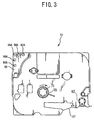
- FIG. 3 is a bottom view of the tape cassette 51.
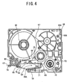
- FIG. 4 is a plan view of a lower case 53 in a condition where an upper case 52 is removed.
- the tape cassette 51 is comprised of the upper case 52 and the lower case 53.
- a support opening 57 and a support opening 55 are formed in the tape cassette 51.
- the support opening 57 supports, in a rotation-enabled manner, a tape spool 68 (see FIG. 4) around which a later-described print tape 67 is wound in such a manner that its separate sheet of paper may face externally.
- the support opening 55 supports a ribbon take-up spool 71 (see FIG. 4) for pulling out and taking up an ink ribbon 69 (see FIG. 4) from a ribbon spool 70 (see FIG. 4) when printing a character etc. on the print tape 67 by using a thermal head (not shown).
- an arm portion 58 is provided at a front side (lower side in FIG. 2) of the tape cassette 51.
- This arm portion 58 guides the print tape 67 (see FIG. 4) pulled out from the tape spool 68 (see FIG. 4) and the ink ribbon 69 (see FIG. 4) pulled out from the ribbon spool 70 (see FIG. 4) so that they may be fed out from an opening 58A.
- a head mounting portion 59 is provided which is mounted with a thermal head of the tape printer 1.
- a first engaging portion 60 is formed which is formed through the tape cassette 51 toward its back side.
- a second engaging portion 61 is formed which is formed through it in a direction orthogonal to the first engaging portion 60 (i.e., n along the wall portion 59A).
- a tape feeding roller 62 is supported by a support opening 63 in such a manner that it can rotate.
- Such the tape feeding roller 62 pulls out the print tape 67 from the tape spool 68 in cooperation with a pressing roller (not shown) that is pressed against the tape feeding roller 62 from the facing side.
- a pair of upper and lower regulation members 64 and 65 are provided, to guide in a width direction the print tape 67 with a character etc. printed thereon in such a manner that this tape may be regulated on the downstream side of the thermal head.
- an identification portion 66 is formed which is identification means of the disclosure.
- a plurality of identification openings 66A is formed having a predetermined pattern for detecting a type of the tape cassette 51, for example, the type of the tape cassette 51 is identified on the basis of a width of each print tape 67 and whether the tape is of a recyclable type.
- FIG. 4 is a plan view of the lower case 53 in a condition where the upper case 52 is removed, in which at a rear part (upper part in FIG. 4) in the lower case 53 the tape spool 68 around which the print tape 67 is wound is arranged via said support opening 57 in such a manner that it can rotate.
- the ribbon spool 70 around which the ink ribbon 69 is wound is arranged in such a manner that it can rotate.
- the ribbon take-up spool 71 for pulling out the ink ribbon 69 from the ribbon spool 70 and taking up the ink ribbon 69 which has been consumed through printing of a character etc. is arranged via said support opening 55 between the tape spool 68 and the ribbon spool 70 in such a manner that it can rotate.
- the print tape 67 is pulled out from the tape spool 68 when the tape feeding roller 62 operates with the pressing roller (which is provided on the side of the tape printer 1), not shown. Then, the pulled out print tape 67 passes through the opening 58A in the arm portion 58 to a front side (lower side in FIG. 4) of the head mounting portion 59 and is discharged from a tape discharge portion 74 to an outside of the tape cassette 51. Further, the ink ribbon 69 is pulled out from the ribbon spool 70 via the ribbon take-up spool 71. The pulled out ink ribbon 69 passes through the opening 58A in the arm portion 58 to the front side (lower side in FIG. 4) of the head mounting portion 59 and is guided by a guide portion 75 formed into each of the regulation members 64 and 65 to be taken up around the ribbon take-up spool 71.
- the ribbon take-up spool 71 is mounted at its lower part with a clutch spring 76 so that when the ribbon take-up spool 71 is reversed, this clutch spring 76 may prevent the taken-up ink ribbon 69 from being loosened.
- the plurality of identification openings 66A formed in the identification portion 66 is provided.
- FIG. 5 is an explanatory diagram showing a relationship between the identification portion 66 and the detection switches 6.
- a pattern according to which the identification openings 66A are formed in the identification portion 66 is supposed to depend on a type of each of the tape cassettes 51.
- the switch terminal shaft 6A of each of the plurality of detection switches 6 arranged on the cassette detection portion 5 of the tape printer 1 is inserted into each of the identification openings 66A. Then, the detection switch 6 that faces a position where the identification opening 66A is provided is turned OFF.
- the detection switch 6 that faces a portion where the identification opening 66A is not provided is turned ON because it is pressed down by the switch terminal shaft 6A by a base of the identification portion 66.
- the type of the tape cassette 51 is detected on the basis of a combination of turned-ON/turned-OFF states of this plurality of detection switches 6.
- the tape type is identified on the basis of the turned-ON/turned-OFF states of the five detection switches as listed below.
- the identification opening 66A need not necessarily be opening-shaped, instead, a notched concave portion may be formed by notching an outer surface of the identification portion 66 in such a manner that it may cave in toward a width-directional center of the tape cassette 51.
- any shape besides a opening shape may be formed as far as the detection switch 6 can be turned OFF when the switch terminal shaft 6A of the facing detection switch 6 is inserted.
- FIG. 6 is a block diagram showing a control configuration of the tape printer 1.
- FIG. 7 is a schematic diagram showing a configuration of an ROM 102.
- FIG. 8 is a schematic diagram showing a configuration of an RAM 104.
- FIG. 9 is an image diagram showing an example of frame data.
- FIG. 10 is an image diagram showing an example of halftone-dot data for a recycle mark.
- a control circuit portion 100 is formed as a core on a control substrate.
- the control circuit portion 100 comprises a CPU 101, an input/output interface 105, a CGROM 103, the ROM 102, and the RAM 104.
- the CPU 101 controls relevant devices.
- the input/output interface 105 is connected to the CPU 101 via a data bus 106. It is to be noted that dot pattern data for use in display as related to each of a lot of characters is stored in the CGROM 103 in a condition where it is correlated with code data.
- the input/output interface 105 is connected the keyboard portion 3, the detection switches 6, a display controller (hereinafter abbreviated as LCDC) 109, a driver circuit 107, and a driver circuit 108.
- the LCDC109 has a video RAM, not shown, for outputting display data to the liquid crystal display 4.
- the driver circuit 107 drives a thermal head 11.
- the driver circuit 108 drives a tape feeding motor 37.
- the ROM 102 has a CG data storage area 121, a program storage area 122, a frame data storage area 123, a recycle mark halftone-dot data storage area 124, and a miscellaneous data area 125.
- Dot pattern print data pieces for a lot of characters such as alphabets and symbols classified for each of typefaces such as a Gothic typeface and Mincho typeface are stored in the CG data storage area 121 for each of the typefaces as much as six print character sizes (16-dot, 24-dot, 32-dot, 48-dot, 64-dot, and 96-dot sizes) as correlated with code data. It further stores graphic pattern data for use in printing of a graphic image.
- the program storage area 122 are stored a display drive control program, a print drive control program, a recycle mark print control program, and a variety of other programs.
- the display drive control program controls the LCDC 109 in accordance with code data of a character such as an alphabet or a numeric character input from the keyboard portion 3.
- the print drive control program reads data from a print buffer 142 (see FIG. 8), to drive the thermal head 11 or the tape feeding motor 37.
- the recycle mark print control program provides control on whether a recycle mark should be printed.
- the variety of other programs include a program required in control of the tape printer 1. In this configuration, the CPU 101 performs various operations based on the variety of programs stored inn the ROM 102.
- the frame data storage area 123 further stores data of a frame to be composed with data of a text in a case where the frame is printed on the text.
- the frame data relates to a common decoration frame such as an angular frame and an angular round frame as well as a recycle frame prepared in the present embodiment to indicate that a relevant tape can be recycled.
- frame data is comprised of strips that correspond to vertical and horizontal sides of a frame, so that by using these sides as many as corresponding to a width of the tape, a shape of the frame is created.
- recycle frame data 204 is comprised of a horizontal strip 201, a front-part vertical strip 202, and a rear-part vertical strip 203.
- angular frame data 214 comprises a horizontal strip 211, a front-part vertical strip 212, and a rear-part vertical strip 213, and round frame data 224 comprises a horizontal frame 221, a front-part vertical strip 222, and a rear-part vertical strip 223.
- halftone-dot data is stored which is used in a case where halftone-dot printing is selected as a recycle mark printing for a recycle mark.
- This halftone-dot data is used in such a manner that by saving one unit of halftone-dot image data 300 beforehand, as shown in FIG. 10, data of a text to be printed may be filled with the halftone-dot image data. It is thus possible to obtain a print result 350 by use of halftone-dot printing such as shown in FIG. 17. More preferably, sections are filled with a character of "RECYCLE” by shifting a print starting position for each of them so that "RECYCLE" may not be broken somewhere along it.
- the frame data storage area 123 and the recycle mark halftone-dot data storage area 124 correspond to print data storage means of the disclosure.
- the RAM 104 has a text buffer 141, the print buffer 142 serving as a print data storage area of the disclosure, a recycle mark addition flag area 143, a recycle frame flag area 144, a frame type area 145, a miscellaneous data area 146, etc.
- the text buffer 141 stores document data entered through the keyboard portion 3.
- the print buffer 142 stores as dot pattern data a plurality of print dot patterns such as characters and symbols, the number of applied pulses representing a quantity of energy generated for each dot.
- the thermal head 11 performs dot printing in accordance with dot pattern data stored in the print buffer 142.
- the recycle mark addition flag area 143 stores a recycle mark addition flag that is set ON when a recycle mark is to be added and set OFF when it is not to be added. Furthermore, the recycle frame flag area 144 stores a recycle frame flag that is set ON when a recycle frame is selected as the recycle mark and set OFF when it is not selected. Further, the frame type area 145 stores a type in a case where a frame is to be printed together with a text.
- the tape printer 1 having the above-described configuration, in a case where characters etc. are entered through a character key on the keyboard portion 3, relevant texts (document data pieces) are sequentially stored in the text buffer 141 of the RAM104. Simultaneously with it, the liquid crystal display 4 displays on it a dot pattern that corresponds to a character etc. entered via the keyboard portion 3 based on a dot pattern generation control program and a display drive control program. Further, the thermal head 11 is driven through the driver circuit 107 to thereby print data of the dot pattern stored in the print buffer 142, in synchronization with which the tape feeding motor 37 conducts control on feeding of a tape via the driver circuit 108. It is to be noted that the thermal head 11 prints a character etc. on the tape when its heat elements are selectively heated and driven via the driver circuit 107 for each line of print dots.
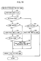
- FIG. 11 is a flowchart of a main routine of print control processing for the tape printer 1.
- FIG. 12 is a flowchart of a subroutine of edit processing which is performed at S4 of FIG. 11.
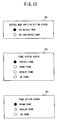
- FIG. 13 is an explanatory illustration showing an example of a setting screen.
- FIG. 14 is a flowchart of a subroutine of recycle mark addition setting processing which is performed at S42 of FIG. 12.
- FIG. 15 is a flowchart of a subroutine of print processing which is performed at S6 of FIG. 11.
- FIG. 16 is a flowchart of a subroutine of recycle tape print image creation processing which is performed at S65 of FIG. 15.
- FIG. 17 is an explanatory illustration showing an example of a print image to which a recycle mark is added.
- FIG. 18 is a flowchart of a subroutine of non-recyclable tape print image creation processing which is performed at S66 of FIG. 15.
- the process decides whether the operation commands printing (S5). If such is the case (YES at S5), print processing is performed (S6). Details of the print processing are described later with reference to FIGS. 15 to 18. If the operation does not command printing (NO at S5), the process performs other processing of the tape printer 1 (S7) and returns to S2 to wait for entry. Similarly, after the edit processing (S4) and the print processing (S6), the process returns to S2 to wait for entry. The above processing is performed repeatedly in the tape printer 1.
- the process decides whether entry by an operator commands setting of addition of a recycle mark (S41) .
- a recycle mark that indicates that it is recyclable is composed with print data and can be printed together with it when printing is performed.
- the operator can select whether to add such a recycle mark. In this case, it is decided whether setting has been made to add such a recycle mark.
- a setting screen 200 such as shown in FIG. 13 for adding recycle marks is displayed to perform recycle mark addition setting processing (S42). Details of the recycle mark addition setting processing is described later with reference to FIG. 14.
- the process decides whether the setting involves frame setting of setting whether to add a frame that encloses a text to be printed (S43).
- a decoration frame that encloses texts can be printed.
- a recycle frame that uses a recycle mark as a frame can be printed as added to the text.
- next the process confirms the recycle mark addition flag area 143 of the RAM 104, to decide whether it is set to add a recycle mark (S44). If such is the case (YES at S44), the process displays a frame setting screen 210 including a recycle frame as an option as shown in FIG. 13, so that the operator selects a desired frame from the screen (S45) .
- the operator can select a radio button of a desired frame from among "RECYCLE FRAME", “ROUND FRAME”, “ANGULAR FRAME”, and "NO FRAME" and settle it by pressing an OK key on the keyboard portion 3.
- the first option is in a selected state, so that by pressing UP arrow and DOWN arrow keys, the option can be changed. This holds true also with manipulation of the radio button on the following variety of setting screen.
- the process decides whether the recycle frame is selected (S46) and, if such is the case (YES at S46), sets "ON" the recycle frame flag to be stored in the recycle frame flag area 144 and the process returns to FIG. 11. Otherwise (NO at S46), the process sets "OFF" the recycle frame flag to be stored in the recycle frame flag area 144 (S49) and the process returns to FIG. 11.
- a frame setting screen 220 not including a recycle frame as an option is displayed, so that the operator selects a desired frame from it (S48).
- the operator can select a radio button of any one of "ROUND FRAME” , "ANGULAR FRAME", and "NO FRAME” and settle it by pressing the OK key on the keyboard portion 3. Then, the process sets "OFF" the recycle frame flag to be stored in the recycle frame flag area 144 of the RAM 104 and the process returns to FIG. 11.
- recycle mark addition setting processing which is performed at S42 of FIG. 12 with reference to FIG. 14.
- the recycle mark addition setting screen 200 such as shown in FIG. 13 is displayed (S421).
- the operator selects a radio button of either "ADD RECYCLE MARK” or “NOT ADD RECYCLE MARK” and settles it by pressing the OK key on the keyboard portion 3.
- the process decides whether "ADD RECYCLE MARK" is selected (S422). If such is the case (YES at S422), the process sets "ON” the recycle mark addition flag to be stored in the recycle mark addition flag area 143 of the RAM 104 (S423) and the process returns to FIG. 12. Otherwise (NO at S422), the process sets "OFF" the recycle mark addition flag to be stored in the recycle mark addition flag area 143 of the RAM 104 (S424) and the process returns to FIG. 12.
- the process acquires a result of detecting a tape type input from the cassette detection portion 5 (S61). Based on the detection result, the process decides whether the tape cassette 51 is housed (S62) . As described above, in the present embodiment, in a case where the fourth detection switch is set “OFF” and the fifth detection switch is set "OFF" in the cassette detection portion 5, it is decided that the tape cassette 51 is not housed in the tape cassette housing portion 2.
- the process decides whether the tape is of a recyclable type (S64). Specifically, if an input from the switch sensor indicates turned-ON state of the first detection switch, the tape is decided to be of a recyclable type. If the tape is of a recyclable type (YES at S64), a print image of the recyclable tape is created (S65) . Details of this recyclable tape print image creation processing are described later with reference to FIG. 16. If the tape is not of a recyclable type (NO at S64), a print image of the non-recyclable tape is created (S66) . Details of this non-recyclable tape print image creation processing are described later with reference to FIG. 18.
- the process actually drives the thermal head based on the print data to perform printing on the tape (S67) .
- the process cuts off the printed tape (S68) and the process returns to FIG. 11.
- the process checks the recycle mark addition flag area 143 of the RAM 104, to decide whether it is set to add a recycle mark (S652). If the recycle mark addition flag is set "ON", that is, if it is set to add a recycle mark (YES at S652), the process checks the frame type area 145 of the RAM 104, to decide whether it is set to attach a frame (S653).
- the process invokes frame data of a relevant type from the frame data storage area 123 of the ROM 102 and creates a print image of the frame (S654). Then, the process decides whether the frame is a recyclable type (S655). If such is the case (YES at S655), the process composes a frame image as created at S654 and a print image of the text created at S651, to create a print image 310 such as shown in FIG. 17 and store it in the print buffer 142 (S656). Now a print image in the case of using a recycle frame as a recycle mark has been created, the process returns to FIG. 15.
- a print image by use of a recycle frame is not limited to such a print image 310 as shown in FIG. 17, which is totally surrounded by recycle marks.
- various forms may be possible as shown in FIG. 17 including, for example, a print image 320 in which a text is sandwiched vertically by added recycle marks, a print image 330 in which it is sandwiched horizontally by added recycle marks, and a print image 340 in which a recycle mark is added in the lower vicinity of the end portion of a printed text.
- characters "RECYCLE” are used as a recycle mark in FIG. 17, "RECYCLABLE” may be displayed or converted into a pattern or symbols instead of characters.
- halftone-dot printing is to be performed for the recycle mark, so that the process invokes halftone-dot data from the recycle mark halftone-dot data storage area 124 of the ROM 102, to create its print image (S657) .
- one unit of halftone-dot image data 300 such as shown in FIG. 10 covers the text data for the length of the text to create the print image.
- the process composes the created halftone-dot print image and the print image of the text created at S651, to create a print image 350 such as shown in FIG. 17 and store it in the print buffer 142 (S656).
- the process checks the frame type area 145 of the RAM104, to decide whether it is set to attach a frame (S658). If such is the case (YES at S658), the process invokes frame data of a relevant type from the frame data storage area 123 of the ROM 102, to create a print image of the frame (S659). Then, the process composes the created halftone-dot print image and the print image of the text created at S651 and stores it in the print buffer 142 (S656) . Now a print image in the case of printing with a frame being attached in place of a recycle mark has been created, the process returns to FIG. 15.
- the operator can make setting to select whether a recycle mark should be composed with a text and printed. Furthermore, in a case where he has selected to print a recycle mark, he can also select whether it is to be printed by using a recycle frame or by using halftone dots for the recycle mark. He can select any one of a plurality of options in accordance with use.
- non-recyclable tape print image creation processing to be performed at S66 of FIG. 15, with reference to FIG. 18.
- the process creates a print image of a text saved in the text buffer 141 of the RAM 104 and stores it in the print buffer 142 (S661).
- the process checks the recycle mark addition flag area 143 of the RAM104, to decide whether it is set to add a recycle mark (S662). If the recycle mark addition flag is set "ON", that is, if it is set to add a recycle mark (YES at S662), the process checks the frame type area 145 of the RAM 104, to decide whether it is set to attach a frame (S663). If such is the case (YES at S663), the process decides whether a frame type is of a recycle frame (S664).
- the process checks the frame type area 145 of the RAM 104, and invokes frame data of a relevant type from the frame data storage area 123 of the ROM 102, to create a print image of the frame (S665). Then, the process composes the created frame print image and the print image of the text created at S661 and stores it in the print buffer 142 (S666). Now a print image in the case of printing with a frame being attached in place of a recycle mark has been created, the process returns to FIG. 15.
- the process checks the frame type area 145 of the RAM 104, to decide whether it is set to attach a frame (S668). If such is the case (YES at S668), the process checks the frame type area 145 of the RAM 104 and invokes frame data of a relevant type from the frame data storage area 123 of the ROM 102 and create a print image of the frame (S665) . Then, the process composes the created frame print image and the text print image created at S661 and stores it in the print buffer 142 (S666) . Now a print image in the case of printing with a frame being attached has been created, the process returns to FIG. 15.
- recycle mark addition setting processing to be performed at S42 of FIG. 12 may be performed as follows. The following will describe recycle mark addition setting processing of another example with reference to FIG. 19.
- FIG. 19 is a flowchart showing another example of the recycle mark addition setting processing.
- the process acquires a result of detection on a tape type input from the cassette detection portion 5 (S521) . Based on the detection result, the process decides whether the tape cassette 51 is housed (S522). As described above, in the present embodiment, if the fourth detection switch 6 is set OFF and the fifth detection switch 6 is OFF in the cassette detection portion 5, the tape cassette 51 is not housed in the tape cassette housing portion 2. If the tape cassette 51 is not housed in the tape cassette housing portion 2 (NO at S522), printing cannot be performed, so that a message appears on the liquid crystal display 4 for prompting to mount the tape cassette 51 or error notification processing involving production of a beep sound is performed (S528) .
- the process decides whether the tape is of a recyclable type (S523) . Specifically, if an input from the switch sensor indicates turned-ON state of the first detection switch 6, the tape is decided to be of a recyclable type. If the tape is of a recyclable type (YES at S523), the recycle mark addition setting screen 200 such as shown in FIG. 13 is displayed (S524) . On this recycle mark addition setting screen 200, the operator selects a radio button of either "ADD RECYCLE MARK" or "NOT ADD RECYCLE MARK" and settles it by pressing the OK key on the keyboard portion 3.
- the process decides whether "ADD RECYCLE MARK" is selected (S525). If such is the case (YES at S525), the process sets "ON” the recycle mark addition flag to be stored in the recycle mark addition flag area 143 of the RAM104 (S526) and the process returns to FIG. 12. IF "ADD RECYCLE MARK" is not selected (NO at S525), the process sets "OFF” the recycle mark addition flag to be stored in the recycle mark addition flag area 143 of the RAM104 (S527) and the process returns to FIG. 12.
- the process checks beforehand whether a mounted tape is recyclable.
- the CPU 101 that composes a text print image and a recycle mark print image at S656 of FIG. 16 functions as composition means of the disclosure. Further, the CPU 101 that performs recycle mark addition setting processing of S42 of FIG. 12 and in FIGS. 14 and 19 functions as recycle mark print setting means of the disclosure. Further, the CPU 101 that notifies of a non-recyclable tape at S528 of FIG. 19 by performing error processing functions as notification means of the disclosure.
- the process in a case where detection means has detected that a tape housed in a mounted tape cassette is recyclable, the process composes recycle mark data prepared beforehand and print data of a text etc. and prints it. Therefore, it is possible to immediately recognize that an already printed tape can be recycled in a condition where this tape is pasted, thereby easily sorting out a sheet of paper etc. to which the already printed tape is pasted.
- the disclosed tape printer comprises recycle mark print setting means for setting whether to print said recycle mark data, so that if said detection means has detected that the tape is of a recyclable type and said recycle mark print setting means has set to print said recycle mark data, said composition means may compose the recycle mark data with the print data.
- recycle mark print setting means for setting whether to print a recycle mark data, so that only if it is set to print a recycle mark, recycle mark data can be composed with print data and printed. Whether to print a recycle mark or not can be selected according to the use by the operator in such cases that the recycle mark is not desired in considerations of appearance or that it is decided that a recycle mark is not necessarily indicated because only recyclable tape is used.
- said recycle mark print setting means if said recycle mark print setting means has set to print the recycle mark data in a case where said detection means has not detected that the tape is of a recyclable type, said composition means need not compose the recycle mark data with the print data.
- the recycle mark print setting means has set to print a recycle mark, the recycle mark is not printed if a mounted tape is not of a recyclable type. Even if the operator wishes to print a recycle mark on a non-recyclable tape by mistake, printing is not performed, so that it is possible to avoid non-recyclable tape from being indicated to be recyclable mistakenly.
- the disclosed tape printer may comprise notification means for notifying of the tape being not recyclable if said recycle mark print setting means has set to print the recycle mark in a case where said detection means has not detected that the tape is of a recyclable type.
- notification means for notifying of the tape being not recyclable if said recycle mark print setting means has set to print the recycle mark in a case where said detection means has not detected that the tape is of a recyclable type.
- the disclosed tape print program can be executed by a computer, thus having actions and effects described hitherto.
- identification means can be used to decide whether a housed tape is of a recyclable type, so that by mounting this tape cassette into the tape printer, it is possible to compose a recycle mark with print data of a text etc. and print it on the tape.
Abstract
Description
- The disclosure relates to a tape printer for performing printing on a tape housed in a tape cassette, a tape print program, and a tape cassette used in the tape printer.
- Conventionally, a tape printer for creating a tape shaped label is known. In this tape printer, a tape cassette is configured in an attachable/detachable manner. This tape cassette houses a tape and a print ribbon as a print medium so that printing may be performed on the tape by using a thermal head. As said tape, any one of a plurality of types of tapes having different widths and structures can be used, so that a plurality of types of tape cassettes is available which may house these tapes.
- Recently, as people become more and more recycling conscious, paper is also recycled in many cases. In such a case, for example, if a tape or a label is pasted to a sheet of paper, the tape and the label need to be removed from the sheet of paper before it is taken out for recycling unless the tape and the label are also recyclable. Such a problem occurs that recycling may not progress smoothly owing to such a complicated labor. To solve such a problem, for example, a recyclable adhesive tape such as described in
Japanese Patent Application Laid Open Publication No. 2000-86986 - In a case where such a recyclable tape or label is used, if it is not shown to an operator that it is recyclable, such a precious recyclable effect cannot be utilized. Therefore, for example, a recycle mark is currently printed on a separate sheet of paper of a label. Further, the above-described
Japanese Patent Application Laid Open Publication No. 2000-86986 - For the same reason as in the case of an adhesive tape, it is considered to use a recyclable tape even for use in the above-described tape printer, to promote recycling.
- However, for example, even in a case where an indication saying that the tape is recyclable may be put on a separate sheet of paper of a recyclable tape used in a tape printer, the separate sheet of paper is already peeled off from the tape before it is discarded, so that it cannot be known whether the tape can be recycled. Further, even if a message is printed on a tape to indicate that it can be recycled, it may not be sure that the message can be read depending on a length of the tape actually used. Further, some operators may think it is not preferable in appearances to perform printing on a tape that has a message of recyclable-ness on it.
- To solve these problems above, the disclosure has been developed, and it is one object of the disclosure to provide such a tape printer, tape print program, and tape cassette for use in the same printer that a recyclable type of a printed tape can be easily read.
- To achieve the object above, according to a first aspect, a tape printer for performing printing on a tape contained in a tape cassette comprises detection means for detecting a type of the tape contained in said tape cassette, print data storage means for storing print data, a print head for performing printing on said tape based on the print data stored in said print data storage means, recycle mark storage means for storing data of a recycle mark comprised of a character, a graphic, a symbol, or a combination thereof to indicate a recyclable tyype, composition means for composing, if the type of said tape is detected by the detection means to be of recyclable-ness, the recycle mark data stored in the recycle mark storage means with the print data stored in said print data storage means, and print control means for controlling said print head so that it may perform printing based on composite data, which is the print data composed by the composition means.
- According to a second aspect, a tape print program causes a computer to function as the various processing means of said invention.
- According to a third aspect, a tape cassette is used in a tape printer comprising detection means for detecting a type of the tape contained in said tape cassette, print data storage means for storing print data, a print head for performing printing on said tape based on the print data stored in said print data storage means, recycle mark storage means for storing data of a recycle mark comprised of a character, a graphic, a symbol, or a combination thereof to indicate a recyclable type, composition means for composing, if the type of said tape is detected by the detection means to be of a recyclable type, the recycle mark data stored in the recycle mark storage means with the print data stored in said print data storage means, and print control means for controlling said print head so that it may perform printing based on composite data, which is the print data composed by the composition means and the cassette being mounted to the tape printer in an attachable/detachable manner, comprising identification means for identifying whether said built-in tape is of a recyclable type.
- Exemplary embodiments will be described below in detail with reference to the accompanying drawings in which:
- FIG. 1 is a plan view showing a condition where a cap of a tape housing portion of a disclosed tape printer is removed;
- FIG. 2 is a perspective view of a tape cassette;
- FIG. 3 is a bottom view of the tape cassette;
- FIG. 4 is a plan view of a lower case in a condition where an upper case is removed;
- FIG. 5 is an explanatory diagram showing a relationship between an identification portion and a detection switch;
- FIG. 6 is a block diagram showing a control configuration of a tape printer;
- FIG. 7 is a schematic diagram showing a configuration of an ROM;
- FIG. 8 is a schematic diagram showing a configuration of an RAM;
- FIG. 9 is an image diagram showing an example of frame data;
- FIG. 10 is an image diagram showing an example of halftone-dot data for a recycle mark;
- FIG. 11 is a flowchart of a main routine of print control processing for the tape printer;
- FIG. 12 is a flowchart of a subroutine of edit processing which is performed at S4 of FIG. 11;
- FIG. 13 is an explanatory illustration showing an example of a setting screen;
- FIG. 14 is a flowchart of a subroutine of recycle mark addition setting processing which is performed at S42 of FIG. 12;
- FIG. 15 is a flowchart of a subroutine of print processing which is performed at S6 of FIG. 11;
- FIG. 16 is a flowchart of a subroutine of recyclable tape print image creation processing which is performed at S65 of FIG. 15;
- FIG. 17 is an explanatory illustration showing an example of a print image to which a recycle mark is added;
- FIG. 18 is a flowchart of a subroutine of non-recyclable tape print image creation processing which is performed at S66 of FIG. 15; and
- FIG. 19 is a flowchart showing another example of recycle mark addition setting processing.
- The following will describe a best mode with reference to the drawings. FIG. 1 is a plan view showing a condition where a cap of a tape housing portion of a
tape printer 1 of the present invention is removed. - As shown in FIG. 1, a rear part of the
tape printer 1 is equipped with a tapecassette housing portion 2, which is a concave portion for housing a later-described tape cassette 51 (see FIG. 2) . A front part of thetape printer 1, on the other hand, is equipped with akeyboard portion 3 for entering a character and a symbol. On thekeyboard portion 3, a plurality ofkeys 3A is arranged for entering a character, a symbol, and a function command. Further, between the tapecassette housing portion 2 and thekeyboard portion 3, aliquid crystal display 4 is provided. Theliquid crystal display 4 is capable of displaying a character, a symbol, etc. entered through thekeyboard portion 3. - Further, at a right upper corner (as shown in FIG. 1) of the tape
cassette housing portion 2 of thetape printer 1, acassette detection portion 5 is equipped, which is detection means of the disclosure. In thecassette detection portion 5, a plurality of through-holes 19 is formed. Through each through-hole 19, aswitch terminal shaft 6A of a detection switch 6 (see FIG. 5) installed on a detection sensor substrate 80 (see FIG. 5) projects. Thedetection switches 6 are provided to detect whether thetape cassette 51 is mounted in the tapecassette housing portion 2 and detect a type of thetape cassette 51 mounted in the tapecassette housing portion 2 when they are combined with detection openings of thetape cassette 51 as described later. - The following will describe a structure of the
tape cassette 51 mounted in the tapecassette housing portion 2 of thetape printer 1 with reference to FIGS. 2 to 4. FIG. 2 is a perspective view of thetape cassette 51. FIG. 3 is a bottom view of thetape cassette 51. FIG. 4 is a plan view of alower case 53 in a condition where anupper case 52 is removed. - As shown in FIG. 2, the
tape cassette 51 is comprised of theupper case 52 and thelower case 53. In thetape cassette 51, a support opening 57 and a support opening 55 are formed. The support opening 57 supports, in a rotation-enabled manner, a tape spool 68 (see FIG. 4) around which a later-describedprint tape 67 is wound in such a manner that its separate sheet of paper may face externally. The support opening 55 supports a ribbon take-up spool 71 (see FIG. 4) for pulling out and taking up an ink ribbon 69 (see FIG. 4) from a ribbon spool 70 (see FIG. 4) when printing a character etc. on theprint tape 67 by using a thermal head (not shown). - It is to be noted that although only the
support openings upper case 52 are shown in FIG. 2, thesupport openings lower case 53 in such a manner as to face those support openings in theupper case 52. - Further, at a front side (lower side in FIG. 2) of the
tape cassette 51, anarm portion 58 is provided. Thisarm portion 58 guides the print tape 67 (see FIG. 4) pulled out from the tape spool 68 (see FIG. 4) and the ink ribbon 69 (see FIG. 4) pulled out from the ribbon spool 70 (see FIG. 4) so that they may be fed out from anopening 58A. Behind thearm portion 58, ahead mounting portion 59 is provided which is mounted with a thermal head of thetape printer 1. - Moreover, in a
wall portion 59A facing thearm portion 58 in thehead mounting portion 59, a first engagingportion 60 is formed which is formed through thetape cassette 51 toward its back side. Further, in a left side wall of thehead mounting portion 59, a second engagingportion 61 is formed which is formed through it in a direction orthogonal to the first engaging portion 60 (i.e., n along thewall portion 59A). These first and second engagingportions head mounting portion 59 without interference by each of theink ribbons 69 and theprint tape 67. - Furthermore, on the downstream side of the
head mounting portion 59 along a direction in which each of theink ribbons 69 and theprint tape 67 travels, atape feeding roller 62 is supported by asupport opening 63 in such a manner that it can rotate. Such thetape feeding roller 62 pulls out theprint tape 67 from thetape spool 68 in cooperation with a pressing roller (not shown) that is pressed against thetape feeding roller 62 from the facing side. Further, near thetape feeding roller 62, a pair of upper andlower regulation members print tape 67 with a character etc. printed thereon in such a manner that this tape may be regulated on the downstream side of the thermal head. - Further, as shown in FIG. 3, at a left rear edge on a back side of the
tape cassette 51, anidentification portion 66 is formed which is identification means of the disclosure. In thisidentification portion 66, a plurality ofidentification openings 66A is formed having a predetermined pattern for detecting a type of thetape cassette 51, for example, the type of thetape cassette 51 is identified on the basis of a width of eachprint tape 67 and whether the tape is of a recyclable type. - The following will describe an internal configuration of the
tape cassette 51 with reference to FIG. 4. FIG. 4 is a plan view of thelower case 53 in a condition where theupper case 52 is removed, in which at a rear part (upper part in FIG. 4) in thelower case 53 thetape spool 68 around which theprint tape 67 is wound is arranged via saidsupport opening 57 in such a manner that it can rotate. At a front part (lower part in FIG. 4) of thelower case 53, theribbon spool 70 around which theink ribbon 69 is wound is arranged in such a manner that it can rotate. Furthermore, the ribbon take-upspool 71 for pulling out theink ribbon 69 from theribbon spool 70 and taking up theink ribbon 69 which has been consumed through printing of a character etc. is arranged via saidsupport opening 55 between thetape spool 68 and theribbon spool 70 in such a manner that it can rotate. - As described above, the
print tape 67 is pulled out from thetape spool 68 when thetape feeding roller 62 operates with the pressing roller (which is provided on the side of the tape printer 1), not shown. Then, the pulled outprint tape 67 passes through theopening 58A in thearm portion 58 to a front side (lower side in FIG. 4) of thehead mounting portion 59 and is discharged from atape discharge portion 74 to an outside of thetape cassette 51. Further, theink ribbon 69 is pulled out from theribbon spool 70 via the ribbon take-upspool 71. The pulled outink ribbon 69 passes through theopening 58A in thearm portion 58 to the front side (lower side in FIG. 4) of thehead mounting portion 59 and is guided by aguide portion 75 formed into each of theregulation members spool 71. - It is to be noted that the ribbon take-up
spool 71 is mounted at its lower part with aclutch spring 76 so that when the ribbon take-upspool 71 is reversed, thisclutch spring 76 may prevent the taken-upink ribbon 69 from being loosened. - It is to be noted that as shown in FIG. 4 at a right rear edge of the
lower case 53, the plurality ofidentification openings 66A formed in theidentification portion 66 is provided. - The following will describe how to detect the
tape cassette 51 by using theidentification portion 66 and thedetection switch 6 with reference to FIG. 5. FIG. 5 is an explanatory diagram showing a relationship between theidentification portion 66 and the detection switches 6. A pattern according to which theidentification openings 66A are formed in theidentification portion 66 is supposed to depend on a type of each of thetape cassettes 51. Theswitch terminal shaft 6A of each of the plurality ofdetection switches 6 arranged on thecassette detection portion 5 of thetape printer 1 is inserted into each of theidentification openings 66A. Then, thedetection switch 6 that faces a position where theidentification opening 66A is provided is turned OFF. Thedetection switch 6 that faces a portion where theidentification opening 66A is not provided is turned ON because it is pressed down by theswitch terminal shaft 6A by a base of theidentification portion 66. The type of thetape cassette 51 is detected on the basis of a combination of turned-ON/turned-OFF states of this plurality of detection switches 6. In the present embodiment, the tape type is identified on the basis of the turned-ON/turned-OFF states of the five detection switches as listed below.[Table 1] 1st detection switch 2nd detection switch 3rd detection switch 4th detection switch 5th detection switch Recyclability Recyclabl e item ON - - - - Non-recyc lable item OFF - - - - Tape Width 12mm - OFF OFF - - 18mm - OFF ON - - 24mm - ON OFF - - 36mm - ON ON - - Tape type Receptor - - - ON ON Laminate - - - ON OFF Cassette not provided - - - OFF OFF - It is to be noted that the identification opening 66A need not necessarily be opening-shaped, instead, a notched concave portion may be formed by notching an outer surface of the
identification portion 66 in such a manner that it may cave in toward a width-directional center of thetape cassette 51. In short, any shape besides a opening shape may be formed as far as thedetection switch 6 can be turned OFF when theswitch terminal shaft 6A of the facingdetection switch 6 is inserted. - The following will describe an electrical configuration of the
tape printer 1 with reference to FIGS. 6 to 8. FIG. 6 is a block diagram showing a control configuration of thetape printer 1. FIG. 7 is a schematic diagram showing a configuration of anROM 102. FIG. 8 is a schematic diagram showing a configuration of anRAM 104. FIG. 9 is an image diagram showing an example of frame data. FIG. 10 is an image diagram showing an example of halftone-dot data for a recycle mark. - As shown in FIG. 6, in the control configuration of the
tape printer 1, acontrol circuit portion 100 is formed as a core on a control substrate. Thecontrol circuit portion 100 comprises aCPU 101, an input/output interface 105, aCGROM 103, theROM 102, and theRAM 104. TheCPU 101 controls relevant devices. The input/output interface 105 is connected to theCPU 101 via adata bus 106. It is to be noted that dot pattern data for use in display as related to each of a lot of characters is stored in theCGROM 103 in a condition where it is correlated with code data. - Further, to the input/
output interface 105 are connected thekeyboard portion 3, the detection switches 6, a display controller (hereinafter abbreviated as LCDC) 109, adriver circuit 107, and adriver circuit 108. The LCDC109 has a video RAM, not shown, for outputting display data to theliquid crystal display 4. Thedriver circuit 107 drives athermal head 11. Thedriver circuit 108 drives atape feeding motor 37. - Further, as shown in FIG. 7, the
ROM 102 has a CGdata storage area 121, aprogram storage area 122, a framedata storage area 123, a recycle mark halftone-dotdata storage area 124, and amiscellaneous data area 125. Dot pattern print data pieces for a lot of characters such as alphabets and symbols classified for each of typefaces such as a Gothic typeface and Mincho typeface are stored in the CGdata storage area 121 for each of the typefaces as much as six print character sizes (16-dot, 24-dot, 32-dot, 48-dot, 64-dot, and 96-dot sizes) as correlated with code data. It further stores graphic pattern data for use in printing of a graphic image. - Further, in the
program storage area 122 are stored a display drive control program, a print drive control program, a recycle mark print control program, and a variety of other programs. The display drive control program controls theLCDC 109 in accordance with code data of a character such as an alphabet or a numeric character input from thekeyboard portion 3. The print drive control program reads data from a print buffer 142 (see FIG. 8), to drive thethermal head 11 or thetape feeding motor 37. The recycle mark print control program provides control on whether a recycle mark should be printed. The variety of other programs include a program required in control of thetape printer 1. In this configuration, theCPU 101 performs various operations based on the variety of programs stored inn theROM 102. - The frame
data storage area 123 further stores data of a frame to be composed with data of a text in a case where the frame is printed on the text. The frame data relates to a common decoration frame such as an angular frame and an angular round frame as well as a recycle frame prepared in the present embodiment to indicate that a relevant tape can be recycled. As shown in FIG. 9, frame data is comprised of strips that correspond to vertical and horizontal sides of a frame, so that by using these sides as many as corresponding to a width of the tape, a shape of the frame is created. For example, recycleframe data 204 is comprised of ahorizontal strip 201, a front-partvertical strip 202, and a rear-partvertical strip 203. By combining these, print data that comprises a recycle frame and a text frame is created, so that a result of printing such as shown inimages 310 to 340 of FIG. 17 is obtained. Similarly,angular frame data 214 comprises ahorizontal strip 211, a front-partvertical strip 212, and a rear-partvertical strip 213, andround frame data 224 comprises ahorizontal frame 221, a front-partvertical strip 222, and a rear-partvertical strip 223. - Further, in the recycle mark halftone-dot
data storage area 124, halftone-dot data is stored which is used in a case where halftone-dot printing is selected as a recycle mark printing for a recycle mark. This halftone-dot data is used in such a manner that by saving one unit of halftone-dot image data 300 beforehand, as shown in FIG. 10, data of a text to be printed may be filled with the halftone-dot image data. It is thus possible to obtain aprint result 350 by use of halftone-dot printing such as shown in FIG. 17. More preferably, sections are filled with a character of "RECYCLE" by shifting a print starting position for each of them so that "RECYCLE" may not be broken somewhere along it. It is to be noted that the framedata storage area 123 and the recycle mark halftone-dotdata storage area 124 correspond to print data storage means of the disclosure. - Further, as shown in FIG. 8, the
RAM 104 has atext buffer 141, theprint buffer 142 serving as a print data storage area of the disclosure, a recycle markaddition flag area 143, a recycleframe flag area 144, aframe type area 145, amiscellaneous data area 146, etc. Thetext buffer 141 stores document data entered through thekeyboard portion 3. Further, theprint buffer 142 stores as dot pattern data a plurality of print dot patterns such as characters and symbols, the number of applied pulses representing a quantity of energy generated for each dot. Thethermal head 11 performs dot printing in accordance with dot pattern data stored in theprint buffer 142. Further, the recycle markaddition flag area 143 stores a recycle mark addition flag that is set ON when a recycle mark is to be added and set OFF when it is not to be added. Furthermore, the recycleframe flag area 144 stores a recycle frame flag that is set ON when a recycle frame is selected as the recycle mark and set OFF when it is not selected. Further, theframe type area 145 stores a type in a case where a frame is to be printed together with a text. - In the
tape printer 1 having the above-described configuration, in a case where characters etc. are entered through a character key on thekeyboard portion 3, relevant texts (document data pieces) are sequentially stored in thetext buffer 141 of the RAM104. Simultaneously with it, theliquid crystal display 4 displays on it a dot pattern that corresponds to a character etc. entered via thekeyboard portion 3 based on a dot pattern generation control program and a display drive control program. Further, thethermal head 11 is driven through thedriver circuit 107 to thereby print data of the dot pattern stored in theprint buffer 142, in synchronization with which thetape feeding motor 37 conducts control on feeding of a tape via thedriver circuit 108. It is to be noted that thethermal head 11 prints a character etc. on the tape when its heat elements are selectively heated and driven via thedriver circuit 107 for each line of print dots. - The following will describe operations of the
tape printer 1 having the above-described configuration with reference to FIGS. 11 to 18. FIG. 11 is a flowchart of a main routine of print control processing for thetape printer 1. FIG. 12 is a flowchart of a subroutine of edit processing which is performed at S4 of FIG. 11. FIG. 13 is an explanatory illustration showing an example of a setting screen. FIG. 14 is a flowchart of a subroutine of recycle mark addition setting processing which is performed at S42 of FIG. 12. FIG. 15 is a flowchart of a subroutine of print processing which is performed at S6 of FIG. 11. FIG. 16 is a flowchart of a subroutine of recycle tape print image creation processing which is performed at S65 of FIG. 15. FIG. 17 is an explanatory illustration showing an example of a print image to which a recycle mark is added. FIG. 18 is a flowchart of a subroutine of non-recyclable tape print image creation processing which is performed at S66 of FIG. 15. - First, when the
tape printer 1 is actuated upon power application, as shown in FIG. 11, a variety of values and flags are initialized (S1). The process waits until an input is made through the keyboard portion 3 (NO at S2) . If a key input is made (YES at S2), the process decides whether the entry is an operation to command editing (S3) . If such is the case (YES at S3), the edit processing is performed (S4). Details of the edit processing are described later with reference to FIGS. 12 to 14. - If the input is not an edit command (NO at S3), the process decides whether the operation commands printing (S5). If such is the case (YES at S5), print processing is performed (S6). Details of the print processing are described later with reference to FIGS. 15 to 18. If the operation does not command printing (NO at S5), the process performs other processing of the tape printer 1 (S7) and returns to S2 to wait for entry. Similarly, after the edit processing (S4) and the print processing (S6), the process returns to S2 to wait for entry. The above processing is performed repeatedly in the
tape printer 1. - The following will describe the edit processing to be performed at S4 of FIG. 11. First, the process decides whether entry by an operator commands setting of addition of a recycle mark (S41) . In the present embodiment, if the
tape cassette 51 housed in the tapecassette housing portion 2 is a recyclable tape when a text is to be printed, a recycle mark that indicates that it is recyclable is composed with print data and can be printed together with it when printing is performed. The operator can select whether to add such a recycle mark. In this case, it is decided whether setting has been made to add such a recycle mark. - If a recycle mark is to be added (YES at S41), a
setting screen 200 such as shown in FIG. 13 for adding recycle marks is displayed to perform recycle mark addition setting processing (S42). Details of the recycle mark addition setting processing is described later with reference to FIG. 14. - If a recycle mark is not to be added (NO at S41), the process decides whether the setting involves frame setting of setting whether to add a frame that encloses a text to be printed (S43). In the
tape printer 1 of the present embodiment, like an ordinary tape printer, a decoration frame that encloses texts can be printed. Further, as a frame peculiar to the present embodiment, a recycle frame that uses a recycle mark as a frame can be printed as added to the text. - If a frame is to be added (YES at S43), next the process confirms the recycle mark
addition flag area 143 of theRAM 104, to decide whether it is set to add a recycle mark (S44). If such is the case (YES at S44), the process displays aframe setting screen 210 including a recycle frame as an option as shown in FIG. 13, so that the operator selects a desired frame from the screen (S45) . On theframe setting screen 210, as shown in FIG. 13, the operator can select a radio button of a desired frame from among "RECYCLE FRAME", "ROUND FRAME", "ANGULAR FRAME", and "NO FRAME" and settle it by pressing an OK key on thekeyboard portion 3. Further, as for manipulation of the radio button, immediately after theframe setting screen 210 is displayed, the first option is in a selected state, so that by pressing UP arrow and DOWN arrow keys, the option can be changed. This holds true also with manipulation of the radio button on the following variety of setting screen. - Then, the process decides whether the recycle frame is selected (S46) and, if such is the case (YES at S46), sets "ON" the recycle frame flag to be stored in the recycle
frame flag area 144 and the process returns to FIG. 11. Otherwise (NO at S46), the process sets "OFF" the recycle frame flag to be stored in the recycle frame flag area 144 (S49) and the process returns to FIG. 11. - Further, if setting is not made to add a recycle mark in a condition where the recycle mark flag is set "OFF" (NO at S44), as shown in FIG. 13, a
frame setting screen 220 not including a recycle frame as an option is displayed, so that the operator selects a desired frame from it (S48). On theframe setting screen 220, the operator can select a radio button of any one of "ROUND FRAME" , "ANGULAR FRAME", and "NO FRAME" and settle it by pressing the OK key on thekeyboard portion 3. Then, the process sets "OFF" the recycle frame flag to be stored in the recycleframe flag area 144 of theRAM 104 and the process returns to FIG. 11. - If a frame is not to be set (NO at S43), the process performs any other edit processing (S50) and, upon completion of this processing, returns to FIG. 11.
- The following will describe recycle mark addition setting processing which is performed at S42 of FIG. 12 with reference to FIG. 14. First, the recycle mark
addition setting screen 200 such as shown in FIG. 13 is displayed (S421). On such a recycle markaddition setting screen 200, the operator selects a radio button of either "ADD RECYCLE MARK" or "NOT ADD RECYCLE MARK" and settles it by pressing the OK key on thekeyboard portion 3. - Next, the process decides whether "ADD RECYCLE MARK" is selected (S422). If such is the case (YES at S422), the process sets "ON" the recycle mark addition flag to be stored in the recycle mark
addition flag area 143 of the RAM 104 (S423) and the process returns to FIG. 12. Otherwise (NO at S422), the process sets "OFF" the recycle mark addition flag to be stored in the recycle markaddition flag area 143 of the RAM 104 (S424) and the process returns to FIG. 12. - The following will describe print processing which is performed at S6 of FIG. 11 with reference to FIG. 15. First, as shown in FIG. 15, the process acquires a result of detecting a tape type input from the cassette detection portion 5 (S61). Based on the detection result, the process decides whether the
tape cassette 51 is housed (S62) . As described above, in the present embodiment, in a case where the fourth detection switch is set "OFF" and the fifth detection switch is set "OFF" in thecassette detection portion 5, it is decided that thetape cassette 51 is not housed in the tapecassette housing portion 2. If thetape cassette 51 is not housed in the tape cassette housing portion 2 (NO at S62), printing cannot be performed, so that the process displays a message on theliquid crystal display 4 for prompting the operator to mount thetape cassette 51 or performs error processing involving production of a beep sound (S63) and the process returns to FIG. 11. - If the
tape cassette 51 is properly mounted in the tape cassette housing portion 2 (YES at S62), the process decides whether the tape is of a recyclable type (S64). Specifically, if an input from the switch sensor indicates turned-ON state of the first detection switch, the tape is decided to be of a recyclable type. If the tape is of a recyclable type (YES at S64), a print image of the recyclable tape is created (S65) . Details of this recyclable tape print image creation processing are described later with reference to FIG. 16. If the tape is not of a recyclable type (NO at S64), a print image of the non-recyclable tape is created (S66) . Details of this non-recyclable tape print image creation processing are described later with reference to FIG. 18. - When creation of the print image is completed at S65 or S66, the process actually drives the thermal head based on the print data to perform printing on the tape (S67) . When printing is finished, the process cuts off the printed tape (S68) and the process returns to FIG. 11.
- The following will describe recyclable tape print image creation processing to be performed at S65 of FIG. 15 with reference to FIGS. 16 and 17. As shown in FIG. 16, first a print image of a text saved in the
text buffer 141 of the RAM104 is created and stored in the print buffer 142 (S651) . - Next, the process checks the recycle mark
addition flag area 143 of theRAM 104, to decide whether it is set to add a recycle mark (S652). If the recycle mark addition flag is set "ON", that is, if it is set to add a recycle mark (YES at S652), the process checks theframe type area 145 of theRAM 104, to decide whether it is set to attach a frame (S653). - If such is the case (YES at S653), the process invokes frame data of a relevant type from the frame
data storage area 123 of theROM 102 and creates a print image of the frame (S654). Then, the process decides whether the frame is a recyclable type (S655). If such is the case (YES at S655), the process composes a frame image as created at S654 and a print image of the text created at S651, to create aprint image 310 such as shown in FIG. 17 and store it in the print buffer 142 (S656). Now a print image in the case of using a recycle frame as a recycle mark has been created, the process returns to FIG. 15. - A print image by use of a recycle frame is not limited to such a
print image 310 as shown in FIG. 17, which is totally surrounded by recycle marks. Instead, various forms may be possible as shown in FIG. 17 including, for example, aprint image 320 in which a text is sandwiched vertically by added recycle marks, aprint image 330 in which it is sandwiched horizontally by added recycle marks, and aprint image 340 in which a recycle mark is added in the lower vicinity of the end portion of a printed text. Further, although characters "RECYCLE" are used as a recycle mark in FIG. 17, "RECYCLABLE" may be displayed or converted into a pattern or symbols instead of characters. - If it is not set to attach a frame (NO at S653), halftone-dot printing is to be performed for the recycle mark, so that the process invokes halftone-dot data from the recycle mark halftone-dot
data storage area 124 of theROM 102, to create its print image (S657) . Specifically, one unit of halftone-dot image data 300 such as shown in FIG. 10 covers the text data for the length of the text to create the print image. Then, the process composes the created halftone-dot print image and the print image of the text created at S651, to create aprint image 350 such as shown in FIG. 17 and store it in the print buffer 142 (S656). - Even in a case where it is set to attach a frame (YES at S653), if a frame other than the recycle frame is specified (NO at S655), the recycle mark is to be printed using halftone dots, so that the process invokes halftone-dot data from the halftone-dot
data storage area 124 of the ROM102, to create its print image (S657). Then, the process composes a print image of that created frame and a print image of the text created at S651, to create such aprint image 350 as shown in FIG. 17 and store it in the print buffer 142 (S656). When a print image of a recycle mark by use of halftone dots is created, the process returns to FIG. 15. - If it is not set to attach a recycle mark (NO at S652), the process checks the
frame type area 145 of the RAM104, to decide whether it is set to attach a frame (S658). If such is the case (YES at S658), the process invokes frame data of a relevant type from the framedata storage area 123 of theROM 102, to create a print image of the frame (S659). Then, the process composes the created halftone-dot print image and the print image of the text created at S651 and stores it in the print buffer 142 (S656) . Now a print image in the case of printing with a frame being attached in place of a recycle mark has been created, the process returns to FIG. 15. - Further, neither a recycle mark nor a frame is to be attached (NO at S652, NO at S658), the process returns to FIG. 15 in a condition where only a print image of a text is stored in the
print buffer 142. - As described above, in a case where a recyclable tape is mounted, the operator can make setting to select whether a recycle mark should be composed with a text and printed. Furthermore, in a case where he has selected to print a recycle mark, he can also select whether it is to be printed by using a recycle frame or by using halftone dots for the recycle mark. He can select any one of a plurality of options in accordance with use.
- The following will describe non-recyclable tape print image creation processing to be performed at S66 of FIG. 15, with reference to FIG. 18. First, as shown in FIG. 18, the process creates a print image of a text saved in the
text buffer 141 of theRAM 104 and stores it in the print buffer 142 (S661). - Next, the process checks the recycle mark
addition flag area 143 of the RAM104, to decide whether it is set to add a recycle mark (S662). If the recycle mark addition flag is set "ON", that is, if it is set to add a recycle mark (YES at S662), the process checks theframe type area 145 of theRAM 104, to decide whether it is set to attach a frame (S663). If such is the case (YES at S663), the process decides whether a frame type is of a recycle frame (S664). - If any frame other than the recycle frame is specified (NO at S664), the process checks the
frame type area 145 of theRAM 104, and invokes frame data of a relevant type from the framedata storage area 123 of theROM 102, to create a print image of the frame (S665). Then, the process composes the created frame print image and the print image of the text created at S661 and stores it in the print buffer 142 (S666). Now a print image in the case of printing with a frame being attached in place of a recycle mark has been created, the process returns to FIG. 15. - If a recycle frame is specified (YES at S664), the recycle frame cannot be printed because the tape is decided at S64 of FIG. 15 to be non-recyclable, the process ignores specification of a recycle frame and the process returns to FIG. 15 in a condition where only the print image of the text created at S661 is stored in the
print buffer 142. In this case, since a recycle frame is mistakenly specified despite a non-recyclable tape, printing of a frame is not activated; however, it may be configured to print an ordinary frame other than the recycle frame. Further, an error message may be displayed to indicate that the tape is not of a recyclable type. - Also, if it is not set to attach a frame (NO at S663), the process returns to FIG. 15 in a condition where only the print image of the text created at S661 is stored in the
print buffer 142. - If it is not set to add a recycle mark (NO at S662), the process checks the
frame type area 145 of theRAM 104, to decide whether it is set to attach a frame (S668). If such is the case (YES at S668), the process checks theframe type area 145 of theRAM 104 and invokes frame data of a relevant type from the framedata storage area 123 of theROM 102 and create a print image of the frame (S665) . Then, the process composes the created frame print image and the text print image created at S661 and stores it in the print buffer 142 (S666) . Now a print image in the case of printing with a frame being attached has been created, the process returns to FIG. 15. - If it is not set to add a recycle mark and no frame is to be attached (NO at S662, NO at S668), the process returns to FIG. 15 in a condition where only the text print image created at S661 is stored in the
print buffer 142. - As described above, in the case of a non-recyclable tape, even if the operator has mistakenly thinks that a tape can be recycled and has made setting to print a recycle mark, the recycle mark is not printed, thus avoiding preventing a sheet of paper etc. to which the tape is pasted from being recycled.
- It is to be noted that recycle mark addition setting processing to be performed at S42 of FIG. 12 may be performed as follows. The following will describe recycle mark addition setting processing of another example with reference to FIG. 19. FIG. 19 is a flowchart showing another example of the recycle mark addition setting processing.
- As shown in FIG. 19, first the process acquires a result of detection on a tape type input from the cassette detection portion 5 (S521) . Based on the detection result, the process decides whether the
tape cassette 51 is housed (S522). As described above, in the present embodiment, if thefourth detection switch 6 is set OFF and thefifth detection switch 6 is OFF in thecassette detection portion 5, thetape cassette 51 is not housed in the tapecassette housing portion 2. If thetape cassette 51 is not housed in the tape cassette housing portion 2 (NO at S522), printing cannot be performed, so that a message appears on theliquid crystal display 4 for prompting to mount thetape cassette 51 or error notification processing involving production of a beep sound is performed (S528) . - If the
tape cassette 51 is properly mounted in the tape cassette housing portion 2 (YES at S552), the process decides whether the tape is of a recyclable type (S523) . Specifically, if an input from the switch sensor indicates turned-ON state of thefirst detection switch 6, the tape is decided to be of a recyclable type. If the tape is of a recyclable type (YES at S523), the recycle markaddition setting screen 200 such as shown in FIG. 13 is displayed (S524) . On this recycle markaddition setting screen 200, the operator selects a radio button of either "ADD RECYCLE MARK" or "NOT ADD RECYCLE MARK" and settles it by pressing the OK key on thekeyboard portion 3. - Next, the process decides whether "ADD RECYCLE MARK" is selected (S525). If such is the case (YES at S525), the process sets "ON" the recycle mark addition flag to be stored in the recycle mark
addition flag area 143 of the RAM104 (S526) and the process returns to FIG. 12. IF "ADD RECYCLE MARK" is not selected (NO at S525), the process sets "OFF" the recycle mark addition flag to be stored in the recycle markaddition flag area 143 of the RAM104 (S527) and the process returns to FIG. 12. - If the tape is not of a recyclable type (NO at S523), a recycle mark cannot be printed, so that a message is displayed for the operator beforehand to the effect that the tape cannot be recycled or error processing involving production of a beep sound is performed to notify him that the tape cannot be recycled (S528).
- In such a manner, when the recycle mark addition setting processing is performed, the process checks beforehand whether a mounted tape is recyclable. By making it possible to make setting only in the case of a recyclable tape, even if the operator mistakenly thinks that the tape can be recycled and has set to add a recycle mark to it and printed it, actually the printing is not performed because the tape cannot be recycled. It is thus possible to avoid such a situation that the operator notices his misunderstanding after printing is finished.
- It is to be noted that in the above-described embodiment, the
CPU 101 that composes a text print image and a recycle mark print image at S656 of FIG. 16 functions as composition means of the disclosure. Further, theCPU 101 that performs recycle mark addition setting processing of S42 of FIG. 12 and in FIGS. 14 and 19 functions as recycle mark print setting means of the disclosure. Further, theCPU 101 that notifies of a non-recyclable tape at S528 of FIG. 19 by performing error processing functions as notification means of the disclosure. - As described above, according to a disclosed tape printer, in a case where detection means has detected that a tape housed in a mounted tape cassette is recyclable, the process composes recycle mark data prepared beforehand and print data of a text etc. and prints it. Therefore, it is possible to immediately recognize that an already printed tape can be recycled in a condition where this tape is pasted, thereby easily sorting out a sheet of paper etc. to which the already printed tape is pasted.
- Further, the disclosed tape printer comprises recycle mark print setting means for setting whether to print said recycle mark data, so that if said detection means has detected that the tape is of a recyclable type and said recycle mark print setting means has set to print said recycle mark data, said composition means may compose the recycle mark data with the print data. In such a manner, it is possible to select whether to print a recycle mark by using the recycle mark print setting means, so that only if it is set to print a recycle mark, recycle mark data can be composed with print data and printed. Whether to print a recycle mark or not can be selected according to the use by the operator in such cases that the recycle mark is not desired in considerations of appearance or that it is decided that a recycle mark is not necessarily indicated because only recyclable tape is used.
- Further, according to the disclosed tape printer, if said recycle mark print setting means has set to print the recycle mark data in a case where said detection means has not detected that the tape is of a recyclable type, said composition means need not compose the recycle mark data with the print data. In such a manner, even if the recycle mark print setting means has set to print a recycle mark, the recycle mark is not printed if a mounted tape is not of a recyclable type. Even if the operator wishes to print a recycle mark on a non-recyclable tape by mistake, printing is not performed, so that it is possible to avoid non-recyclable tape from being indicated to be recyclable mistakenly.
- Further, the disclosed tape printer may comprise notification means for notifying of the tape being not recyclable if said recycle mark print setting means has set to print the recycle mark in a case where said detection means has not detected that the tape is of a recyclable type. In such a manner, in a case where it is set to add a recycle mark despite that a recyclable tape is not detected, it is to be notified of, so that it is possible to prevent the recycle mark from being set to be printed in a case where the operator misunderstands the type of a tape mounted.
- Further, the disclosed tape print program can be executed by a computer, thus having actions and effects described hitherto.
- Further, according to the disclosed tape cassette, identification means can be used to decide whether a housed tape is of a recyclable type, so that by mounting this tape cassette into the tape printer, it is possible to compose a recycle mark with print data of a text etc. and print it on the tape.
Claims (8)
- A tape printer (1) for performing printing on a tape (67) contained in a tape cassette (51), comprising:detection means (5) for detecting a type of the tape (67) contained in said tape cassette (51);print data storage means for storing print data;a print head (11) for performing printing on said tape (67) based on the print data stored in said print data storage means;recycle mark storage means for storing data of a recycle mark comprised of a character, a graphic, a symbol, or a combination thereof, to be printed on said tape (67), that indicate a recyclable type;composition means (101) for composing, if said tape (67) is detected by the detection means (5) to be of a recyclable type, the recycle mark data stored in the recycle mark storage means with the print data stored in said print data storage means; andprint control means for controlling said print head (11) so that it may perform printing based on composite data, which is the print data composed by the composition means.
- The tape printer according to claim 1, further comprising recycle mark print setting means (101) for setting whether to print said recycle mark data, wherein if said tape (67) is detected by said detection means (5) to be of the recyclable type and said recycle mark data is set by said recycle mark print setting means (101) to be printed, said composition means (10) composes said recycle mark data with said print data.
- The tape printer according to claim 2, wherein if said recycle mark data is set by said recycle mark print setting means (101) to be printed in a case where said tape (67) is not detected by said detection means (5) to be of the recyclable type, said composition means (101) does not compose said recycle mark data with said print data.
- The tape printer according to claim 2 or 3, further comprising notification means (101) for notifying of said tape (67) being not recyclable if, when setting whether to print said recycle mark by using said recycle mark print setting means (101), said tape (67) has been detected by said detection means (5) to be of a non-recyclable type.
- The tape printer according to claim 3, further comprising notification means (101) for notifying of the tape (67) being not recyclable if, when setting whether to print said recycle mark by using said recycle mark print setting means (101), said tape (67) has been detected by said detection means to be of a non-recyclable type.
- The tape printer according to claim 2, wherein if said tape is not detected by said detection means (5) to be of a recyclable type, said recycle mark print setting means (101) makes setting not to print said recycle mark data.
- A tape print program for causing a computer to function as each of processing means of the tape printer according to any one of claims 1 to 6.
- A tape cassette (51) that is used in a tape printer (1) comprising:detection means (5) for detecting a type of the tape (67) contained in said tape cassette (51);print data storage means for storing print data;a print head (11) for performing printing on said tape (67) based on the print data stored in said print data storage means;recycle mark storage means for storing data of a recycle mark comprised of a character, a graphic, a symbol, or a combination thereof, to be printed on said tape (67), that indicate a recyclable type;composition means (10) for composing, if said tape (67) is detected by the detection means (5) to be of a recyclable type, the recycle mark data stored in the recycle mark storage means with the print data stored in said print data storage means; andprint control means for controlling said print head (11) so that it may perform printing based on composite data, which is the print data composed by the composition means (10); andthe cassette (51) being mounted to the tape printer (1) in an attachable/detachable manner, comprising identification means (66) for identifying whether said built-in tape is of the recyclable type.
Applications Claiming Priority (1)
| Application Number | Priority Date | Filing Date | Title |
|---|---|---|---|
| JP2005068310A JP2006248059A (en) | 2005-03-11 | 2005-03-11 | Tape printer, tape printing program, and tape cassette |
Publications (2)
| Publication Number | Publication Date |
|---|---|
| EP1700705A1 true EP1700705A1 (en) | 2006-09-13 |
| EP1700705B1 EP1700705B1 (en) | 2014-02-12 |
Family
ID=36616434
Family Applications (1)
| Application Number | Title | Priority Date | Filing Date |
|---|---|---|---|
| EP06004946.7A Not-in-force EP1700705B1 (en) | 2005-03-11 | 2006-03-10 | Tape printer, tape print program, and tape cassette |
Country Status (3)
| Country | Link |
|---|---|
| US (1) | US7168869B2 (en) |
| EP (1) | EP1700705B1 (en) |
| JP (1) | JP2006248059A (en) |
Cited By (15)
| Publication number | Priority date | Publication date | Assignee | Title |
|---|---|---|---|---|
| CN101934647A (en) * | 2009-06-30 | 2011-01-05 | 兄弟工业株式会社 | Tape cassette |
| US8360667B2 (en) | 2009-06-10 | 2013-01-29 | Brother Kogyo Kabushiki Kaisha | Printer |
| US8384750B2 (en) | 2010-03-31 | 2013-02-26 | Brother Kogyo Kabushiki Kaisha | Printing apparatus |
| US8382389B2 (en) | 2008-12-25 | 2013-02-26 | Brother Kogyo Kabushiki Kaisha | Tape cassette |
| US8564632B2 (en) | 2010-03-31 | 2013-10-22 | Brother Kogyo Kabushiki Kaisha | Thermal printer |
| US8562228B2 (en) | 2008-12-25 | 2013-10-22 | Brother Kogyo Kabushiki Kaisha | Tape printer |
| WO2015027760A1 (en) * | 2013-09-02 | 2015-03-05 | 珠海纳思达企业管理有限公司 | Ribbon cartridge for label printing device |
| US9011028B2 (en) | 2009-03-31 | 2015-04-21 | Brother Kogyo Kabushiki Kaisha | Tape cassette |
| US9132682B2 (en) | 2009-03-31 | 2015-09-15 | Brother Kogyo Kabushiki Kaisha | Tape unit and tape cassette |
| US9174476B2 (en) | 2010-02-26 | 2015-11-03 | Brother Kogyo Kabushiki Kaisha | Ribbon guide in a tape cassette |
| US9352600B2 (en) | 2009-12-16 | 2016-05-31 | Brother Kogyo Kabushiki Kaisha | Tape cassette |
| US9409425B2 (en) | 2009-03-31 | 2016-08-09 | Brother Kogyo Kabushiki Kaisha | Tape cassette |
| US9427988B2 (en) | 2009-03-31 | 2016-08-30 | Brother Kogyo Kabushiki Kaisha | Tape cassette |
| US9616690B2 (en) | 2009-03-31 | 2017-04-11 | Brother Kogyo Kabushiki Kaisha | Tape cassette |
| US9656495B2 (en) | 2009-12-28 | 2017-05-23 | Brother Kogyo Kabushiki Kaisha | Tape cassette |
Families Citing this family (12)
| Publication number | Priority date | Publication date | Assignee | Title |
|---|---|---|---|---|
| EP1955856B1 (en) * | 2007-02-09 | 2013-04-10 | Brother Kogyo Kabushiki Kaisha | Tape printer, tape printing program and tape cassette |
| JP2009241505A (en) * | 2008-03-31 | 2009-10-22 | Casio Comput Co Ltd | Printer, and printing processing program |
| JP5171400B2 (en) * | 2008-06-03 | 2013-03-27 | 京セラドキュメントソリューションズ株式会社 | Image forming apparatus and image forming program |
| US8243292B2 (en) * | 2008-08-29 | 2012-08-14 | Konica Minolta Laboratory U.S.A., Inc. | Systems and methods for printing on recycled media |
| US20100247206A1 (en) * | 2009-03-31 | 2010-09-30 | Brother Kogyo Kabushiki Kaisha | Tape cassette and tape printer |
| JP4947085B2 (en) * | 2009-03-31 | 2012-06-06 | ブラザー工業株式会社 | Tape cassette |
| JP5552761B2 (en) * | 2009-06-30 | 2014-07-16 | ブラザー工業株式会社 | Tape cassette |
| US20100329767A1 (en) * | 2009-06-30 | 2010-12-30 | Brother Kogyo Kabushiki Kaisha | Tape cassette |
| JP5326950B2 (en) * | 2009-09-09 | 2013-10-30 | ブラザー工業株式会社 | Tape cassette |
| US9108449B2 (en) * | 2010-07-29 | 2015-08-18 | Brady Worldwide, Inc. | Cartridge assembly with edge protector |
| JP5686163B2 (en) * | 2013-07-08 | 2015-03-18 | ブラザー工業株式会社 | Tape cassette |
| JP6885352B2 (en) * | 2018-02-05 | 2021-06-16 | ブラザー工業株式会社 | Display devices, display programs, and storage media |
Citations (2)
| Publication number | Priority date | Publication date | Assignee | Title |
|---|---|---|---|---|
| EP0577271A2 (en) * | 1992-06-05 | 1994-01-05 | Brother Kogyo Kabushiki Kaisha | Device for printing on tape |
| JP2000086986A (en) | 1998-09-11 | 2000-03-28 | Oji Kako Kk | Adhesive tape |
Family Cites Families (5)
| Publication number | Priority date | Publication date | Assignee | Title |
|---|---|---|---|---|
| JP3242218B2 (en) * | 1993-07-14 | 2001-12-25 | 株式会社リコー | Image forming device |
| JP3545897B2 (en) * | 1997-02-12 | 2004-07-21 | 株式会社リコー | Color image forming equipment |
| JP4521890B2 (en) * | 1998-06-24 | 2010-08-11 | カシオ計算機株式会社 | Printing device |
| JP2005035202A (en) * | 2003-07-17 | 2005-02-10 | Shinsei Industries Co Ltd | Label printer |
| JP4736457B2 (en) * | 2005-02-17 | 2011-07-27 | ブラザー工業株式会社 | Tape cassette |
-
2005
- 2005-03-11 JP JP2005068310A patent/JP2006248059A/en active Pending
-
2006
- 2006-03-10 EP EP06004946.7A patent/EP1700705B1/en not_active Not-in-force
- 2006-03-10 US US11/372,214 patent/US7168869B2/en not_active Expired - Fee Related
Patent Citations (2)
| Publication number | Priority date | Publication date | Assignee | Title |
|---|---|---|---|---|
| EP0577271A2 (en) * | 1992-06-05 | 1994-01-05 | Brother Kogyo Kabushiki Kaisha | Device for printing on tape |
| JP2000086986A (en) | 1998-09-11 | 2000-03-28 | Oji Kako Kk | Adhesive tape |
Cited By (65)
| Publication number | Priority date | Publication date | Assignee | Title |
|---|---|---|---|---|
| US9498998B2 (en) | 2008-12-25 | 2016-11-22 | Brother Kogyo Kabushiki Kaisha | Tape cassette |
| US11479053B2 (en) | 2008-12-25 | 2022-10-25 | Brother Kogyo Kabushiki Kaisha | Tape cassette |
| US11285749B2 (en) | 2008-12-25 | 2022-03-29 | Brother Kogyo Kabushiki Kaisha | Tape cassette |
| US10744798B2 (en) | 2008-12-25 | 2020-08-18 | Brother Kogyo Kabushiki Kaisha | Tape cassette |
| US8382389B2 (en) | 2008-12-25 | 2013-02-26 | Brother Kogyo Kabushiki Kaisha | Tape cassette |
| US10661589B2 (en) | 2008-12-25 | 2020-05-26 | Brother Kogyo Kabushiki Kaisha | Tape cassette |
| US8562228B2 (en) | 2008-12-25 | 2013-10-22 | Brother Kogyo Kabushiki Kaisha | Tape printer |
| US10189284B2 (en) | 2008-12-25 | 2019-01-29 | Brother Kogyo Kabushiki Kaisha | Tape cassette |
| US9855779B2 (en) | 2008-12-25 | 2018-01-02 | Brother Kogyo Kabushiki Kaisha | Tape cassette |
| US9751349B2 (en) | 2008-12-25 | 2017-09-05 | Brother Kogyo Kabushiki Kaisha | Tape cassette |
| US9682584B2 (en) | 2008-12-25 | 2017-06-20 | Brother Kogyo Kabushiki Kaisha | Tape cassette |
| US9656497B2 (en) | 2008-12-25 | 2017-05-23 | Brother Kogyo Kabushiki Kaisha | Tape cassette |
| US9656496B2 (en) | 2008-12-25 | 2017-05-23 | Brother Kogyo Kabushiki Kaisha | Tape cassette |
| US9649861B2 (en) | 2008-12-25 | 2017-05-16 | Brother Kogyo Kabushiki Kaisha | Tape cassette |
| US9566812B2 (en) | 2008-12-25 | 2017-02-14 | Brother Kogyo Kabushiki Kaisha | Tape cassette |
| US9539838B2 (en) | 2008-12-25 | 2017-01-10 | Brother Kogyo Kabushiki Kaisha | Tape Cassette |
| US9533522B2 (en) | 2008-12-25 | 2017-01-03 | Brother Kogyo Kabushiki Kaisha | Tape cassette |
| US9522556B2 (en) | 2008-12-25 | 2016-12-20 | Brother Kogyo Kabushiki Kaisha | Tape cassette |
| US9511611B2 (en) | 2008-12-25 | 2016-12-06 | Brother Kogyo Kabushiki Kaisha | Tape cassette |
| US9511610B2 (en) | 2008-12-25 | 2016-12-06 | Brother Kogyo Kabushiki Kaisha | Tape cassette |
| US9493016B2 (en) | 2008-12-25 | 2016-11-15 | Brother Kogyo Kabushiki Kaisha | Tape cassette |
| US9511609B2 (en) | 2008-12-25 | 2016-12-06 | Brother Kogyo Kabushiki Kaisha | Tape cassette |
| US9592692B2 (en) | 2009-03-31 | 2017-03-14 | Brother Kogyo Kabushiki Kaisha | Tape cassette |
| US9498987B2 (en) | 2009-03-31 | 2016-11-22 | Brother Kogyo Kabushiki Kaisha | Tape cassette |
| US9498988B2 (en) | 2009-03-31 | 2016-11-22 | Brother Kogyo Kabushiki Kaisha | Tape cassette |
| US9427988B2 (en) | 2009-03-31 | 2016-08-30 | Brother Kogyo Kabushiki Kaisha | Tape cassette |
| US11945217B2 (en) | 2009-03-31 | 2024-04-02 | Brother Kogyo Kabushiki Kaisha | Tape cassette |
| US9409425B2 (en) | 2009-03-31 | 2016-08-09 | Brother Kogyo Kabushiki Kaisha | Tape cassette |
| US9403389B2 (en) | 2009-03-31 | 2016-08-02 | Brother Kogyo Kabushiki Kaisha | Tape cassette |
| US11707938B2 (en) | 2009-03-31 | 2023-07-25 | Brother Kogyo Kabushiki Kaisha | Tape cassette |
| US9381756B2 (en) | 2009-03-31 | 2016-07-05 | Brother Kogyo Kabushiki Kaisha | Tape cassette |
| US9370949B2 (en) | 2009-03-31 | 2016-06-21 | Brother Kogyo Kabushiki Kaisha | Tape cassette |
| US10201988B2 (en) | 2009-03-31 | 2019-02-12 | Brother Kogyo Kabushiki Kaisha | Tape cassette |
| US10201993B2 (en) | 2009-03-31 | 2019-02-12 | Brother Kogyo Kabushiki Kaisha | Tape cassette |
| US9616690B2 (en) | 2009-03-31 | 2017-04-11 | Brother Kogyo Kabushiki Kaisha | Tape cassette |
| US11254149B2 (en) | 2009-03-31 | 2022-02-22 | Brother Kogyo Kabushiki Kaisha | Tape cassette |
| US11052685B2 (en) | 2009-03-31 | 2021-07-06 | Brother Kogyo Kabushiki Kaisha | Tape cassette |
| US9656488B2 (en) | 2009-03-31 | 2017-05-23 | Brother Kogyo Kabushiki Kaisha | Tape cassette |
| US9346296B2 (en) | 2009-03-31 | 2016-05-24 | Brother Kogyo Kabushiki Kaisha | Tape cassette |
| US10744802B2 (en) | 2009-03-31 | 2020-08-18 | Brother Kogyo Kabushiki Kaisha | Tape cassette |
| US10675894B2 (en) | 2009-03-31 | 2020-06-09 | Brother Kogyo Kabushiki Kaisha | Tape cassette |
| US9132682B2 (en) | 2009-03-31 | 2015-09-15 | Brother Kogyo Kabushiki Kaisha | Tape unit and tape cassette |
| US9011028B2 (en) | 2009-03-31 | 2015-04-21 | Brother Kogyo Kabushiki Kaisha | Tape cassette |
| US10618325B2 (en) | 2009-03-31 | 2020-04-14 | Brother Kogyo Kabushiki Kaisha | Tape cassette |
| US10226949B2 (en) | 2009-03-31 | 2019-03-12 | Brother Kogyo Kabushiki Kaisha | Tape cassette |
| US8360667B2 (en) | 2009-06-10 | 2013-01-29 | Brother Kogyo Kabushiki Kaisha | Printer |
| CN101934647A (en) * | 2009-06-30 | 2011-01-05 | 兄弟工业株式会社 | Tape cassette |
| US9676217B2 (en) | 2009-06-30 | 2017-06-13 | Brother Kogyo Kabushiki Kaisha | Tape cassette |
| WO2011001487A1 (en) * | 2009-06-30 | 2011-01-06 | Brother Kogyo Kabushiki Kaisha | Tape cassette and tape printer |
| US9573401B2 (en) | 2009-06-30 | 2017-02-21 | Brother Kogyo Kabushiki Kaisha | Tape cassette |
| US8641304B2 (en) | 2009-06-30 | 2014-02-04 | Brother Kogyo Kabushiki Kaisha | Tape cassette |
| US9802432B2 (en) | 2009-06-30 | 2017-10-31 | Brother Kogyo Kabushiki Kaisha | Tape cassette |
| US11225099B2 (en) | 2009-06-30 | 2022-01-18 | Brother Kogyo Kabushiki Kaisha | Tape cassette |
| US11235600B2 (en) | 2009-12-16 | 2022-02-01 | Brother Kogyo Kabushiki Kaisha | Tape cassette |
| US9352600B2 (en) | 2009-12-16 | 2016-05-31 | Brother Kogyo Kabushiki Kaisha | Tape cassette |
| US10265976B2 (en) | 2009-12-16 | 2019-04-23 | Brother Kogyo Kabushiki Kaisha | Tape cassette |
| US9539837B2 (en) | 2009-12-16 | 2017-01-10 | Brother Kogyo Kabushiki Kaisha | Tape cassette |
| US9656495B2 (en) | 2009-12-28 | 2017-05-23 | Brother Kogyo Kabushiki Kaisha | Tape cassette |
| US11135862B2 (en) | 2009-12-28 | 2021-10-05 | Brother Kogyo Kabushiki Kaisha | Tape cassette with indicator portion having pressing and non-pressing portion for indentifying tape type |
| US10265982B2 (en) | 2009-12-28 | 2019-04-23 | Brother Kogyo Kabushiki Kaisha | Tape cassette |
| US9174476B2 (en) | 2010-02-26 | 2015-11-03 | Brother Kogyo Kabushiki Kaisha | Ribbon guide in a tape cassette |
| US8384750B2 (en) | 2010-03-31 | 2013-02-26 | Brother Kogyo Kabushiki Kaisha | Printing apparatus |
| US8564632B2 (en) | 2010-03-31 | 2013-10-22 | Brother Kogyo Kabushiki Kaisha | Thermal printer |
| WO2015027760A1 (en) * | 2013-09-02 | 2015-03-05 | 珠海纳思达企业管理有限公司 | Ribbon cartridge for label printing device |
| US9415618B2 (en) | 2013-09-02 | 2016-08-16 | Zhuhai Ninestar Management Co., Ltd. | Ribbon cassette for label printing device |
Also Published As
| Publication number | Publication date |
|---|---|
| EP1700705B1 (en) | 2014-02-12 |
| US7168869B2 (en) | 2007-01-30 |
| US20060204304A1 (en) | 2006-09-14 |
| JP2006248059A (en) | 2006-09-21 |
Similar Documents
| Publication | Publication Date | Title |
|---|---|---|
| EP1700705B1 (en) | Tape printer, tape print program, and tape cassette | |
| KR100756758B1 (en) | Information processing apparatus, information processing method, and program | |
| EP1804173A1 (en) | Label creation apparatus and program | |
| JP5392542B2 (en) | Tape printing apparatus, method for creating printed material having cut mark, and storage medium storing printed material creating program having cut mark | |
| JPH08290618A (en) | Label forming tape and label forming printer | |
| US7249902B2 (en) | Tape printing apparatus and tape printing method | |
| JPH07125338A (en) | Tape printing apparatus | |
| JPH10157255A (en) | Image-forming apparatus | |
| JP4075076B2 (en) | Tape printer | |
| EP1040928A1 (en) | Label printer and method of producing a label | |
| JP4407340B2 (en) | Tape printer | |
| JP3249687B2 (en) | Tape-shaped label making device | |
| JP3809194B2 (en) | Tape printer | |
| JP2998829B2 (en) | Tape-shaped label making device | |
| JP2827879B2 (en) | Tape printer | |
| JPH07276746A (en) | Tape printing apparatus | |
| JPH08106370A (en) | Document processor | |
| JP3254653B2 (en) | Tape printer | |
| JP5212726B2 (en) | Tape printer, label creation method, and storage medium storing label creation program | |
| EP0743605A1 (en) | Device and method for displaying enlarged text | |
| JP2006248236A (en) | Cutting control device for tape printer | |
| JP3045026B2 (en) | Tape printer | |
| JP5811810B2 (en) | Printing device | |
| JP2005254499A (en) | Label printer | |
| JP3345208B2 (en) | Document processing device |
Legal Events
| Date | Code | Title | Description |
|---|---|---|---|
| PUAI | Public reference made under article 153(3) epc to a published international application that has entered the european phase |
Free format text: ORIGINAL CODE: 0009012 |
|
| AK | Designated contracting states |
Kind code of ref document: A1 Designated state(s): AT BE BG CH CY CZ DE DK EE ES FI FR GB GR HU IE IS IT LI LT LU LV MC NL PL PT RO SE SI SK TR |
|
| AX | Request for extension of the european patent |
Extension state: AL BA HR MK YU |
|
| 17P | Request for examination filed |
Effective date: 20061229 |
|
| 17Q | First examination report despatched |
Effective date: 20070215 |
|
| AKX | Designation fees paid |
Designated state(s): AT BE BG CH CY CZ DE DK EE ES FI FR GB GR HU IE IS IT LI LT LU LV MC NL PL PT RO SE SI SK TR |
|
| GRAP | Despatch of communication of intention to grant a patent |
Free format text: ORIGINAL CODE: EPIDOSNIGR1 |
|
| INTG | Intention to grant announced |
Effective date: 20130905 |
|
| GRAS | Grant fee paid |
Free format text: ORIGINAL CODE: EPIDOSNIGR3 |
|
| GRAA | (expected) grant |
Free format text: ORIGINAL CODE: 0009210 |
|
| AK | Designated contracting states |
Kind code of ref document: B1 Designated state(s): AT BE BG CH CY CZ DE DK EE ES FI FR GB GR HU IE IS IT LI LT LU LV MC NL PL PT RO SE SI SK TR |
|
| REG | Reference to a national code |
Ref country code: GB Ref legal event code: FG4D |
|
| REG | Reference to a national code |
Ref country code: CH Ref legal event code: EP |
|
| REG | Reference to a national code |
Ref country code: AT Ref legal event code: REF Ref document number: 651970 Country of ref document: AT Kind code of ref document: T Effective date: 20140215 |
|
| REG | Reference to a national code |
Ref country code: IE Ref legal event code: FG4D |
|
| REG | Reference to a national code |
Ref country code: DE Ref legal event code: R096 Ref document number: 602006040248 Country of ref document: DE Effective date: 20140327 |
|
| REG | Reference to a national code |
Ref country code: NL Ref legal event code: VDEP Effective date: 20140212 |
|
| REG | Reference to a national code |
Ref country code: AT Ref legal event code: MK05 Ref document number: 651970 Country of ref document: AT Kind code of ref document: T Effective date: 20140212 |
|
| REG | Reference to a national code |
Ref country code: LT Ref legal event code: MG4D |
|
| PG25 | Lapsed in a contracting state [announced via postgrant information from national office to epo] |
Ref country code: IS Free format text: LAPSE BECAUSE OF FAILURE TO SUBMIT A TRANSLATION OF THE DESCRIPTION OR TO PAY THE FEE WITHIN THE PRESCRIBED TIME-LIMIT Effective date: 20140612 Ref country code: LT Free format text: LAPSE BECAUSE OF FAILURE TO SUBMIT A TRANSLATION OF THE DESCRIPTION OR TO PAY THE FEE WITHIN THE PRESCRIBED TIME-LIMIT Effective date: 20140212 |
|
| PG25 | Lapsed in a contracting state [announced via postgrant information from national office to epo] |
Ref country code: AT Free format text: LAPSE BECAUSE OF FAILURE TO SUBMIT A TRANSLATION OF THE DESCRIPTION OR TO PAY THE FEE WITHIN THE PRESCRIBED TIME-LIMIT Effective date: 20140212 Ref country code: FI Free format text: LAPSE BECAUSE OF FAILURE TO SUBMIT A TRANSLATION OF THE DESCRIPTION OR TO PAY THE FEE WITHIN THE PRESCRIBED TIME-LIMIT Effective date: 20140212 Ref country code: CY Free format text: LAPSE BECAUSE OF FAILURE TO SUBMIT A TRANSLATION OF THE DESCRIPTION OR TO PAY THE FEE WITHIN THE PRESCRIBED TIME-LIMIT Effective date: 20140212 Ref country code: NL Free format text: LAPSE BECAUSE OF FAILURE TO SUBMIT A TRANSLATION OF THE DESCRIPTION OR TO PAY THE FEE WITHIN THE PRESCRIBED TIME-LIMIT Effective date: 20140212 Ref country code: SE Free format text: LAPSE BECAUSE OF FAILURE TO SUBMIT A TRANSLATION OF THE DESCRIPTION OR TO PAY THE FEE WITHIN THE PRESCRIBED TIME-LIMIT Effective date: 20140212 Ref country code: ES Free format text: LAPSE BECAUSE OF FAILURE TO SUBMIT A TRANSLATION OF THE DESCRIPTION OR TO PAY THE FEE WITHIN THE PRESCRIBED TIME-LIMIT Effective date: 20140212 Ref country code: PT Free format text: LAPSE BECAUSE OF FAILURE TO SUBMIT A TRANSLATION OF THE DESCRIPTION OR TO PAY THE FEE WITHIN THE PRESCRIBED TIME-LIMIT Effective date: 20140612 |
|
| PG25 | Lapsed in a contracting state [announced via postgrant information from national office to epo] |
Ref country code: BE Free format text: LAPSE BECAUSE OF FAILURE TO SUBMIT A TRANSLATION OF THE DESCRIPTION OR TO PAY THE FEE WITHIN THE PRESCRIBED TIME-LIMIT Effective date: 20140212 Ref country code: LV Free format text: LAPSE BECAUSE OF FAILURE TO SUBMIT A TRANSLATION OF THE DESCRIPTION OR TO PAY THE FEE WITHIN THE PRESCRIBED TIME-LIMIT Effective date: 20140212 |
|
| PG25 | Lapsed in a contracting state [announced via postgrant information from national office to epo] |
Ref country code: RO Free format text: LAPSE BECAUSE OF FAILURE TO SUBMIT A TRANSLATION OF THE DESCRIPTION OR TO PAY THE FEE WITHIN THE PRESCRIBED TIME-LIMIT Effective date: 20140212 Ref country code: CZ Free format text: LAPSE BECAUSE OF FAILURE TO SUBMIT A TRANSLATION OF THE DESCRIPTION OR TO PAY THE FEE WITHIN THE PRESCRIBED TIME-LIMIT Effective date: 20140212 Ref country code: DK Free format text: LAPSE BECAUSE OF FAILURE TO SUBMIT A TRANSLATION OF THE DESCRIPTION OR TO PAY THE FEE WITHIN THE PRESCRIBED TIME-LIMIT Effective date: 20140212 Ref country code: EE Free format text: LAPSE BECAUSE OF FAILURE TO SUBMIT A TRANSLATION OF THE DESCRIPTION OR TO PAY THE FEE WITHIN THE PRESCRIBED TIME-LIMIT Effective date: 20140212 |
|
| REG | Reference to a national code |
Ref country code: CH Ref legal event code: PL |
|
| REG | Reference to a national code |
Ref country code: DE Ref legal event code: R097 Ref document number: 602006040248 Country of ref document: DE |
|
| PG25 | Lapsed in a contracting state [announced via postgrant information from national office to epo] |
Ref country code: PL Free format text: LAPSE BECAUSE OF FAILURE TO SUBMIT A TRANSLATION OF THE DESCRIPTION OR TO PAY THE FEE WITHIN THE PRESCRIBED TIME-LIMIT Effective date: 20140212 Ref country code: SK Free format text: LAPSE BECAUSE OF FAILURE TO SUBMIT A TRANSLATION OF THE DESCRIPTION OR TO PAY THE FEE WITHIN THE PRESCRIBED TIME-LIMIT Effective date: 20140212 Ref country code: MC Free format text: LAPSE BECAUSE OF FAILURE TO SUBMIT A TRANSLATION OF THE DESCRIPTION OR TO PAY THE FEE WITHIN THE PRESCRIBED TIME-LIMIT Effective date: 20140212 |
|
| PLBE | No opposition filed within time limit |
Free format text: ORIGINAL CODE: 0009261 |
|
| STAA | Information on the status of an ep patent application or granted ep patent |
Free format text: STATUS: NO OPPOSITION FILED WITHIN TIME LIMIT |
|
| REG | Reference to a national code |
Ref country code: IE Ref legal event code: MM4A |
|
| 26N | No opposition filed |
Effective date: 20141113 |
|
| PG25 | Lapsed in a contracting state [announced via postgrant information from national office to epo] |
Ref country code: LI Free format text: LAPSE BECAUSE OF NON-PAYMENT OF DUE FEES Effective date: 20140331 Ref country code: IE Free format text: LAPSE BECAUSE OF NON-PAYMENT OF DUE FEES Effective date: 20140310 Ref country code: CH Free format text: LAPSE BECAUSE OF NON-PAYMENT OF DUE FEES Effective date: 20140331 |
|
| REG | Reference to a national code |
Ref country code: FR Ref legal event code: PLFP Year of fee payment: 10 |
|
| REG | Reference to a national code |
Ref country code: DE Ref legal event code: R097 Ref document number: 602006040248 Country of ref document: DE Effective date: 20141113 |
|
| PG25 | Lapsed in a contracting state [announced via postgrant information from national office to epo] |
Ref country code: IT Free format text: LAPSE BECAUSE OF FAILURE TO SUBMIT A TRANSLATION OF THE DESCRIPTION OR TO PAY THE FEE WITHIN THE PRESCRIBED TIME-LIMIT Effective date: 20140212 |
|
| PG25 | Lapsed in a contracting state [announced via postgrant information from national office to epo] |
Ref country code: SI Free format text: LAPSE BECAUSE OF FAILURE TO SUBMIT A TRANSLATION OF THE DESCRIPTION OR TO PAY THE FEE WITHIN THE PRESCRIBED TIME-LIMIT Effective date: 20140212 |
|
| REG | Reference to a national code |
Ref country code: FR Ref legal event code: PLFP Year of fee payment: 11 |
|
| PG25 | Lapsed in a contracting state [announced via postgrant information from national office to epo] |
Ref country code: BG Free format text: LAPSE BECAUSE OF FAILURE TO SUBMIT A TRANSLATION OF THE DESCRIPTION OR TO PAY THE FEE WITHIN THE PRESCRIBED TIME-LIMIT Effective date: 20140212 |
|
| PGFP | Annual fee paid to national office [announced via postgrant information from national office to epo] |
Ref country code: FR Payment date: 20160223 Year of fee payment: 11 Ref country code: GB Payment date: 20160224 Year of fee payment: 11 |
|
| PG25 | Lapsed in a contracting state [announced via postgrant information from national office to epo] |
Ref country code: GR Free format text: LAPSE BECAUSE OF FAILURE TO SUBMIT A TRANSLATION OF THE DESCRIPTION OR TO PAY THE FEE WITHIN THE PRESCRIBED TIME-LIMIT Effective date: 20140513 |
|
| PG25 | Lapsed in a contracting state [announced via postgrant information from national office to epo] |
Ref country code: HU Free format text: LAPSE BECAUSE OF FAILURE TO SUBMIT A TRANSLATION OF THE DESCRIPTION OR TO PAY THE FEE WITHIN THE PRESCRIBED TIME-LIMIT; INVALID AB INITIO Effective date: 20060310 Ref country code: TR Free format text: LAPSE BECAUSE OF FAILURE TO SUBMIT A TRANSLATION OF THE DESCRIPTION OR TO PAY THE FEE WITHIN THE PRESCRIBED TIME-LIMIT Effective date: 20140212 Ref country code: LU Free format text: LAPSE BECAUSE OF NON-PAYMENT OF DUE FEES Effective date: 20140310 |
|
| PGFP | Annual fee paid to national office [announced via postgrant information from national office to epo] |
Ref country code: DE Payment date: 20160324 Year of fee payment: 11 |
|
| REG | Reference to a national code |
Ref country code: DE Ref legal event code: R119 Ref document number: 602006040248 Country of ref document: DE |
|
| GBPC | Gb: european patent ceased through non-payment of renewal fee |
Effective date: 20170310 |
|
| REG | Reference to a national code |
Ref country code: FR Ref legal event code: ST Effective date: 20171130 |
|
| PG25 | Lapsed in a contracting state [announced via postgrant information from national office to epo] |
Ref country code: DE Free format text: LAPSE BECAUSE OF NON-PAYMENT OF DUE FEES Effective date: 20171003 Ref country code: FR Free format text: LAPSE BECAUSE OF NON-PAYMENT OF DUE FEES Effective date: 20170331 |
|
| PG25 | Lapsed in a contracting state [announced via postgrant information from national office to epo] |
Ref country code: GB Free format text: LAPSE BECAUSE OF NON-PAYMENT OF DUE FEES Effective date: 20170310 |