EP1700580B1 - Endoluminally placed vascular graft - Google Patents
Endoluminally placed vascular graft Download PDFInfo
- Publication number
- EP1700580B1 EP1700580B1 EP06008389A EP06008389A EP1700580B1 EP 1700580 B1 EP1700580 B1 EP 1700580B1 EP 06008389 A EP06008389 A EP 06008389A EP 06008389 A EP06008389 A EP 06008389A EP 1700580 B1 EP1700580 B1 EP 1700580B1
- Authority
- EP
- European Patent Office
- Prior art keywords
- stent
- lining
- vessel
- shaft
- delivery system
- Prior art date
- Legal status (The legal status is an assumption and is not a legal conclusion. Google has not performed a legal analysis and makes no representation as to the accuracy of the status listed.)
- Expired - Lifetime
Links
Images


Classifications
-
- A—HUMAN NECESSITIES
- A61—MEDICAL OR VETERINARY SCIENCE; HYGIENE
- A61F—FILTERS IMPLANTABLE INTO BLOOD VESSELS; PROSTHESES; DEVICES PROVIDING PATENCY TO, OR PREVENTING COLLAPSING OF, TUBULAR STRUCTURES OF THE BODY, e.g. STENTS; ORTHOPAEDIC, NURSING OR CONTRACEPTIVE DEVICES; FOMENTATION; TREATMENT OR PROTECTION OF EYES OR EARS; BANDAGES, DRESSINGS OR ABSORBENT PADS; FIRST-AID KITS
- A61F2/00—Filters implantable into blood vessels; Prostheses, i.e. artificial substitutes or replacements for parts of the body; Appliances for connecting them with the body; Devices providing patency to, or preventing collapsing of, tubular structures of the body, e.g. stents
- A61F2/02—Prostheses implantable into the body
- A61F2/04—Hollow or tubular parts of organs, e.g. bladders, tracheae, bronchi or bile ducts
- A61F2/06—Blood vessels
- A61F2/07—Stent-grafts
-
- A—HUMAN NECESSITIES
- A61—MEDICAL OR VETERINARY SCIENCE; HYGIENE
- A61F—FILTERS IMPLANTABLE INTO BLOOD VESSELS; PROSTHESES; DEVICES PROVIDING PATENCY TO, OR PREVENTING COLLAPSING OF, TUBULAR STRUCTURES OF THE BODY, e.g. STENTS; ORTHOPAEDIC, NURSING OR CONTRACEPTIVE DEVICES; FOMENTATION; TREATMENT OR PROTECTION OF EYES OR EARS; BANDAGES, DRESSINGS OR ABSORBENT PADS; FIRST-AID KITS
- A61F2/00—Filters implantable into blood vessels; Prostheses, i.e. artificial substitutes or replacements for parts of the body; Appliances for connecting them with the body; Devices providing patency to, or preventing collapsing of, tubular structures of the body, e.g. stents
- A61F2/95—Instruments specially adapted for placement or removal of stents or stent-grafts
-
- A—HUMAN NECESSITIES
- A61—MEDICAL OR VETERINARY SCIENCE; HYGIENE
- A61F—FILTERS IMPLANTABLE INTO BLOOD VESSELS; PROSTHESES; DEVICES PROVIDING PATENCY TO, OR PREVENTING COLLAPSING OF, TUBULAR STRUCTURES OF THE BODY, e.g. STENTS; ORTHOPAEDIC, NURSING OR CONTRACEPTIVE DEVICES; FOMENTATION; TREATMENT OR PROTECTION OF EYES OR EARS; BANDAGES, DRESSINGS OR ABSORBENT PADS; FIRST-AID KITS
- A61F2/00—Filters implantable into blood vessels; Prostheses, i.e. artificial substitutes or replacements for parts of the body; Appliances for connecting them with the body; Devices providing patency to, or preventing collapsing of, tubular structures of the body, e.g. stents
- A61F2/82—Devices providing patency to, or preventing collapsing of, tubular structures of the body, e.g. stents
- A61F2/86—Stents in a form characterised by the wire-like elements; Stents in the form characterised by a net-like or mesh-like structure
- A61F2/90—Stents in a form characterised by the wire-like elements; Stents in the form characterised by a net-like or mesh-like structure characterised by a net-like or mesh-like structure
- A61F2/91—Stents in a form characterised by the wire-like elements; Stents in the form characterised by a net-like or mesh-like structure characterised by a net-like or mesh-like structure made from perforated sheet material or tubes, e.g. perforated by laser cuts or etched holes
- A61F2/915—Stents in a form characterised by the wire-like elements; Stents in the form characterised by a net-like or mesh-like structure characterised by a net-like or mesh-like structure made from perforated sheet material or tubes, e.g. perforated by laser cuts or etched holes with bands having a meander structure, adjacent bands being connected to each other
-
- A—HUMAN NECESSITIES
- A61—MEDICAL OR VETERINARY SCIENCE; HYGIENE
- A61F—FILTERS IMPLANTABLE INTO BLOOD VESSELS; PROSTHESES; DEVICES PROVIDING PATENCY TO, OR PREVENTING COLLAPSING OF, TUBULAR STRUCTURES OF THE BODY, e.g. STENTS; ORTHOPAEDIC, NURSING OR CONTRACEPTIVE DEVICES; FOMENTATION; TREATMENT OR PROTECTION OF EYES OR EARS; BANDAGES, DRESSINGS OR ABSORBENT PADS; FIRST-AID KITS
- A61F2/00—Filters implantable into blood vessels; Prostheses, i.e. artificial substitutes or replacements for parts of the body; Appliances for connecting them with the body; Devices providing patency to, or preventing collapsing of, tubular structures of the body, e.g. stents
- A61F2/95—Instruments specially adapted for placement or removal of stents or stent-grafts
- A61F2/958—Inflatable balloons for placing stents or stent-grafts
-
- A—HUMAN NECESSITIES
- A61—MEDICAL OR VETERINARY SCIENCE; HYGIENE
- A61F—FILTERS IMPLANTABLE INTO BLOOD VESSELS; PROSTHESES; DEVICES PROVIDING PATENCY TO, OR PREVENTING COLLAPSING OF, TUBULAR STRUCTURES OF THE BODY, e.g. STENTS; ORTHOPAEDIC, NURSING OR CONTRACEPTIVE DEVICES; FOMENTATION; TREATMENT OR PROTECTION OF EYES OR EARS; BANDAGES, DRESSINGS OR ABSORBENT PADS; FIRST-AID KITS
- A61F2/00—Filters implantable into blood vessels; Prostheses, i.e. artificial substitutes or replacements for parts of the body; Appliances for connecting them with the body; Devices providing patency to, or preventing collapsing of, tubular structures of the body, e.g. stents
- A61F2/02—Prostheses implantable into the body
- A61F2/04—Hollow or tubular parts of organs, e.g. bladders, tracheae, bronchi or bile ducts
- A61F2/06—Blood vessels
- A61F2/07—Stent-grafts
- A61F2002/072—Encapsulated stents, e.g. wire or whole stent embedded in lining
-
- A—HUMAN NECESSITIES
- A61—MEDICAL OR VETERINARY SCIENCE; HYGIENE
- A61F—FILTERS IMPLANTABLE INTO BLOOD VESSELS; PROSTHESES; DEVICES PROVIDING PATENCY TO, OR PREVENTING COLLAPSING OF, TUBULAR STRUCTURES OF THE BODY, e.g. STENTS; ORTHOPAEDIC, NURSING OR CONTRACEPTIVE DEVICES; FOMENTATION; TREATMENT OR PROTECTION OF EYES OR EARS; BANDAGES, DRESSINGS OR ABSORBENT PADS; FIRST-AID KITS
- A61F2/00—Filters implantable into blood vessels; Prostheses, i.e. artificial substitutes or replacements for parts of the body; Appliances for connecting them with the body; Devices providing patency to, or preventing collapsing of, tubular structures of the body, e.g. stents
- A61F2/02—Prostheses implantable into the body
- A61F2/04—Hollow or tubular parts of organs, e.g. bladders, tracheae, bronchi or bile ducts
- A61F2/06—Blood vessels
- A61F2/07—Stent-grafts
- A61F2002/075—Stent-grafts the stent being loosely attached to the graft material, e.g. by stitching
-
- A—HUMAN NECESSITIES
- A61—MEDICAL OR VETERINARY SCIENCE; HYGIENE
- A61F—FILTERS IMPLANTABLE INTO BLOOD VESSELS; PROSTHESES; DEVICES PROVIDING PATENCY TO, OR PREVENTING COLLAPSING OF, TUBULAR STRUCTURES OF THE BODY, e.g. STENTS; ORTHOPAEDIC, NURSING OR CONTRACEPTIVE DEVICES; FOMENTATION; TREATMENT OR PROTECTION OF EYES OR EARS; BANDAGES, DRESSINGS OR ABSORBENT PADS; FIRST-AID KITS
- A61F2/00—Filters implantable into blood vessels; Prostheses, i.e. artificial substitutes or replacements for parts of the body; Appliances for connecting them with the body; Devices providing patency to, or preventing collapsing of, tubular structures of the body, e.g. stents
- A61F2/82—Devices providing patency to, or preventing collapsing of, tubular structures of the body, e.g. stents
- A61F2002/826—Devices providing patency to, or preventing collapsing of, tubular structures of the body, e.g. stents more than one stent being applied sequentially
Definitions
- the present invention relates generally to the field of medical devices, and more particularly, to a graft to re-line a debulked vessel.
- Arterial stenosis is a disease of the artery wherein a portion of the vessel becomes occluded, primarily with plaque (atheroma) containing cholesterol, lipid material, macrophages and proliferating smooth muscle cells, consequently restricting blood flow and causing further complications.
- plaque theroma
- Another, less invasive method of treatment includes balloon catheter angioplasty, where a balloon catheter is inserted into the diseased portion of the vessel and inflated, pushing the atheroma outward and opening the vessel. While balloon catheter angioplasty is much less invasive than bypass surgery, it does not enjoy similar success rates due to frequent restenosis of the vessel.
- stents and other similar endoluminal devices may be inserted to keep the vessel open following angioplasty. Cellular infiltration through the stents' mesh-like structure makes the use of bare stents less than optimal, particularly in longer (>5 cm) regions. Consequently, the stent may be covered with a biocompatible material such as polytetrafluoroethylene (PTFE) to prevent cellular infiltration.
- PTFE polytetrafluoroethylene
- Endarterectomy is a method for treating occluded portions of a vessel where the atheroma is surgically removed, along with the inner two layers (intima and media) of the three-layered artery. Following the endarterectomy, only the adventitia layer remains, thus the vessel can be prone to cellular accumulation and thrombosis.
- Artherectomy is a method for treating occluded blood vessels where a mechanical device is inserted into the vessel, removing atheroma by cutting or grinding the plaque and creating an open channel. Similar to endarterectomy, this procedure can trigger a cellular response that leads to thrombosis and/or restenosis of the vessel.
- Debulking is simply the removal of atheroma, plaque and other tissue to restore blood flow in a vessel.
- the vessel can be re-lined with PTFE or other biocompatible materials.
- US-A-4 787 899 discloses a device for implantation within a tubular body vessel.
- the device comprises a hollow graft made of a deformable material having a high tissue ingrowth rate.
- the graft has a plurality of substantially evenly spaced circumferential bifolds along its length. The length of the graft is selected by the user, and is typically selected to be longer than the diseased portion of the lumen to be repaired.
- a delivery system is provided for placing the graft into the body vessel.
- the delivery system includes a rod whose distal end is provided with a hollow tip, within which tip the distal end of the graft is located upon delivery to the body vessel.
- WO-A-97/10778 discloses a combination of a delivery system and a device for relining a tubular body vessel in accordance with the pre-characterising section of claim 1.
- a delivery system and a device for re-lining a tubular body vessel, the device comprising:
- implantation device comprise, inter alia, a delivery system and a stent for relining blood vessels.
- a delivery system for relining blood vessels.
- a graft containing a stent or other fixation device is deployed slightly distal to the debulked section of the vessel.
- a small balloon on the shaft of the delivery catheter is inflated to ensure good opposition of the graft to the vessel wall.
- the delivery system is removed through the newly implanted graft, which is sutured proximally to the debulked vessel.
- a graft with an attached stent or other support structure to a debulked vessel.
- the replacement lining is delivered to the desired site by using a delivery system, including an atraumatic tip to house the stent, a sliding hub attached to the graft lining material, and an inner shaft connected to the tip.
- the distal stent is bonded, attached or encapsulated to the graft material.
- the graft material can either be supported, unsupported, or a combination of the two to resist compression.
- the distal portion is compressed into the atraumatic tip for delivery to the desired site within the treated vessel.
- a self-expanding stent is used for this purpose so that the deployment of the stent occurs quickly, as soon as it is released from the atraumatic tip, thus ensuring that the stent can be deployed at the pre-selected location without migration in either direction within the vessel.
- the atraumatic tip is connected to an inner shaft that extends through the compressed stent and graft material to the proximal end of the delivery device.
- the connection between the tip and the shaft allows the device to be maneuvered as it is being inserted into the vessel.
- a balloon is positioned to be inside of the stent after the stent is removed from the atraumatic tip. Once the stent is removed from the atraumatic tip and expands to come into contact with the vessel wall, the balloon can be inflated to ensure a good fit to the vessel wall.
- a sliding hub is attached to the proximal end of the graft lining material so that the distal stent can be pulled out of the atraumatic tip. After the delivery system is removed from the vessel and the graft lining material is pulled taut, the sliding hub is cut off of the graft lining material and the lining material is sutured to the treated vessel.
- the present invention satisfies the need for a replacement lining for a vessel. This is accomplished by bonding, attaching or encapsulating a stent at one end of a biocompatible plastic lining material and loading the stent and lining into a delivery system including an atraumatic tip, a sliding hub and an inner shaft with a balloon.
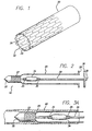
- Fig. 1 illustrates a preferred embodiment of the replacement lining of the present invention.
- a distal end of a replacement lining 20 is shown with a shadow view of a stent 22 attached thereto.
- the stent 22 may be attached to the lining 20 at its distal end in any number of ways including, but not limited to, direct bonding, bonding with the use of an adhesive material, and encapsulation with the use of an additional tubular portion of ePTFE.
- the stent 22 can be attached to the luminal or abluminal surface of the lining, or in the case of encapsulation, the stent can have the lining as its luminal or abluminal surface.
- the lining is a biocompatible graft material, which in the preferred embodiment is expanded polytetrafluoroethylene (ePTFE).
- ePTFE expanded polytetrafluoroethylene
- the preferred ePTFE is one optimized for bond strength as described in U.S. Patent 5,749,880 .
- the stent 22 is self-expanding, thus not requiring any external force to conform to the sides of the vessel wall in which it is placed.
- many other stent configurations are possible, including various self-expanding and balloon-expandable stents.
- Fig. 1 shows encapsulation of the stent 22 as the attachment method to the lining 20.
- the stent 22 is encapsulated between two layers of ePTFE 24 and 26 by utilizing a mandrel assembly. Once the appropriate ePTFE coverings are placed onto the luminal and abluminal surfaces, the stent 22 is encapsulated within the replacement lining 20 at the lining's distal end by connecting or bonding the luminal covering 26 to the abluminal covering 24.
- the replacement lining 20 represents the continuation of the ePTFE covering whether it be a continuation of the abluminal covering 24 from the stent to the proximal end of the device 10 (see Fig. 2 ), the luminal covering 26, or both luminal and abluminal coverings 24 and 26. Encapsulation can be accomplished by a number of methods as is well-known in the art.
- Fig 2 illustrates a cross-section of the delivery system 10 containing the replacement lining 20 before introduction into the vessel of a patient.
- the delivery system 10 contains an atraumatic tip 32 that encloses the stent 22 in a small-diameter state, after it has been reduced in size by any of the known loading methods.
- Attached to the atraumatic tip 32, extending the length of the delivery system 10, is a shaft 30 that connects the tip 32 to a stopper 36.
- a hub 38 Built into the stopper 36 is a hub 38 for the inflation of an optional balloon 34 located proximally a short distance from the loaded stent 22 along the shaft 30.
- the optional balloon 34 has radiopaque markers 35 situated at both ends to reveal the proximal and distal ends of the balloon 34 to assist in the positioning of the balloon 34 with respect to the stent 22.
- the stent 22 is attached to the biocompatible replacement lining 20 at the distal end thereof.
- a sliding hub 28 is attached to the lining 20 to pull back the replacement lining 20 from the atraumatic tip 32 and deploy the stent 22 and replacement lining 20 within a vessel.
- Figs. 3A through 3D illustrate the replacement lining 20 as it is deployed within a vessel 40.
- the delivery system 10 is introduced into the vessel 40 through a single entry point (not shown), distal to the end of the endarterectomy or atherectomy, in which the replacement lining 20 is to be implanted.
- the delivery system 10 can be manipulated through the vessel 40 by the stopper 36 due to the rigidity of the shaft 30, which is connected proximally to the stopper 36 and distally to the atraumatic tip 32 (shown in Fig. 2 ).
- markers can be placed on or encapsulated within the replacement liner 20, on the stent 22, and/or on the optional balloon 34 (as shown in Figs. 2-4 ) when included as a part of the device 10.
- the stent 22 is removed from the atraumatic tip 32 and deployed within the vessel 40 as shown in Fig. 3B .
- the deployment of the stent 22 is preferably accomplished by holding the stopper 36 steady while pulling the sliding hub 28, attached to lining 20, toward the stopper 36.
- This action pulls the stent 22 attached to a distal end of the lining 20 out of the atraumatic tip 32, allowing the stent 22 to self-expand to its pre-loaded diameter to bring it and the attached lining 20 in close proximity to the vessel wall 42.
- the stopper 36 can be pushed toward the sliding hub 28 while the hub is held steady, thereby pushing the atraumatic tip 32 off of the stent 22.
- the optional balloon 34 when present, is positioned proximal to the stent 22 so that removal of the stent 22 from the atraumatic tip 32 places the expanding stent 22 over the top of the balloon 34 as shown in Fig. 3B .
- the balloon 34 which is then within the lumen created by the stent 22 as the stent 22 expands close to the vessel wall 42, can be inflated to come into contact with the stent 22 as shown in Fig. 3C , thus ensuring a tight fit to the vessel wall 42.
- the delivery system 10 is withdrawn from the vessel 40 through the replacement lining 20.
- the stopper 36 with atraumatic tip 32 in tow, is pulled through the lining 20 and out of the single incision site (not shown).
- the sliding hub 28 Prior to removing the delivery system 10, the sliding hub 28 is detached from the lining 20 by cutting the lining material near the hub 28. The remaining lining material is then surgically attached to the vessel 40 wall through suturing or other accepted medical procedures, thus completing the proximal anastomosis.
- Fig. 4 illustrates an alternate embodiment of the vascular graft device and delivery system of the present invention.
- a delivery system 100 contains many of the same features as those of the delivery system 10 shown in Fig. 2 , including the atraumatic tip 32, the shaft 30 that connects the atraumatic tip 32 to the stopper 36, and the balloon 34.
- the stent 22 that is initially constrained within the atraumatic tip 32, there are several small balloon-expandable stents 42, 52, and 62 located at axially spaced apart intervals along the replacement lining 20. These stents can be expanded by the balloon 34 as it is withdrawn in a proximal direction.
- any vessel irregularity can be tailored according to stents that are expanded. It should be appreciated that any number of stents can be placed along the replacement lining 20. By having numerous stents placed at spaced apart intervals, the physician is permitted great flexibility in tailoring the present invention to each individual procedure.
Abstract
Description
- The present invention relates generally to the field of medical devices, and more particularly, to a graft to re-line a debulked vessel.
- Arterial stenosis is a disease of the artery wherein a portion of the vessel becomes occluded, primarily with plaque (atheroma) containing cholesterol, lipid material, macrophages and proliferating smooth muscle cells, consequently restricting blood flow and causing further complications. Traditionally, arterial stenosis has been treated by surgical construction of a bypass channel to connect healthy parts of the vessel around the atheroma. While the bypass method may produce good results, a major disadvantage is the invasiveness of the surgery because the procedure requires general anesthesia and a substantial post-surgical healing period.
- Another, less invasive method of treatment includes balloon catheter angioplasty, where a balloon catheter is inserted into the diseased portion of the vessel and inflated, pushing the atheroma outward and opening the vessel. While balloon catheter angioplasty is much less invasive than bypass surgery, it does not enjoy similar success rates due to frequent restenosis of the vessel. To overcome this problem, stents and other similar endoluminal devices may be inserted to keep the vessel open following angioplasty. Cellular infiltration through the stents' mesh-like structure makes the use of bare stents less than optimal, particularly in longer (>5 cm) regions. Consequently, the stent may be covered with a biocompatible material such as polytetrafluoroethylene (PTFE) to prevent cellular infiltration.
- Endarterectomy is a method for treating occluded portions of a vessel where the atheroma is surgically removed, along with the inner two layers (intima and media) of the three-layered artery. Following the endarterectomy, only the adventitia layer remains, thus the vessel can be prone to cellular accumulation and thrombosis.
- Artherectomy is a method for treating occluded blood vessels where a mechanical device is inserted into the vessel, removing atheroma by cutting or grinding the plaque and creating an open channel. Similar to endarterectomy, this procedure can trigger a cellular response that leads to thrombosis and/or restenosis of the vessel.
- Another term for endarterectomy and artherectomy is "debulking." Debulking is simply the removal of atheroma, plaque and other tissue to restore blood flow in a vessel. To prevent the cellular response that leads to thrombosis and/or restenosis following a debulking procedure, the vessel can be re-lined with PTFE or other biocompatible materials.
- Many delivery systems have been used for introducing stents, grafts, and other endoluminal devices into bodily vessels with minimum invasiveness. One problem with a number of these systems, however, is that they require multiple components and procedural steps to deliver and deploy the device against the vessel wall. In addition, grafts and other endoluminal devices used to currently re-line vessels are not optimal due to problems with effectively anchoring the device within the vessel.
-
US-A-4 787 899 discloses a device for implantation within a tubular body vessel. The device comprises a hollow graft made of a deformable material having a high tissue ingrowth rate. The graft has a plurality of substantially evenly spaced circumferential bifolds along its length. The length of the graft is selected by the user, and is typically selected to be longer than the diseased portion of the lumen to be repaired. A delivery system is provided for placing the graft into the body vessel. The delivery system includes a rod whose distal end is provided with a hollow tip, within which tip the distal end of the graft is located upon delivery to the body vessel. -
WO-A-97/10778 - According to the present invention there is provided a combination of a delivery system and a device for re-lining a tubular body vessel,
the device comprising: - a tubular lining made from a biocompatible material and having a proximal end and a distal end; and
- a stent attached to said distal end of said lining and for fixing said lining within said vessel; and
the delivery system comprising:- a hollow atraumatic tip; and
- a shaft;
- There follows a detailed description of two illustrated, preferred embodiments of implantation device. These devices comprise, inter alia, a delivery system and a stent for relining blood vessels. In the preferred arrangements, following debulking procedures, a graft containing a stent or other fixation device is deployed slightly distal to the debulked section of the vessel. A small balloon on the shaft of the delivery catheter is inflated to ensure good opposition of the graft to the vessel wall. Next, the delivery system is removed through the newly implanted graft, which is sutured proximally to the debulked vessel.
- It is an object of this invention to provide an endoluminal vascular graft device to re-line a debulked vessel as a less invasive alternative to traditional surgical bypass.
- It is another object of this invention to provide an endoluminal vascular graft device that has a minimal profile when loaded into an insertion system, can be seen with fluoroscopic imaging and can be deployed quickly and easily.
- It is yet another object of this invention to provide a delivery system to introduce the endoluminal vascular graft device quickly, easily and effectively within the debulked vessel.
- These and additional objects are accomplished by delivering a graft with an attached stent or other support structure to a debulked vessel. The replacement lining is delivered to the desired site by using a delivery system, including an atraumatic tip to house the stent, a sliding hub attached to the graft lining material, and an inner shaft connected to the tip.
- To prepare the replacement lining for delivery, the distal stent is bonded, attached or encapsulated to the graft material. The graft material can either be supported, unsupported, or a combination of the two to resist compression. The distal portion is compressed into the atraumatic tip for delivery to the desired site within the treated vessel. Ideally, a self-expanding stent is used for this purpose so that the deployment of the stent occurs quickly, as soon as it is released from the atraumatic tip, thus ensuring that the stent can be deployed at the pre-selected location without migration in either direction within the vessel.
- The atraumatic tip is connected to an inner shaft that extends through the compressed stent and graft material to the proximal end of the delivery device. The connection between the tip and the shaft allows the device to be maneuvered as it is being inserted into the vessel. Optionally coupled to the shaft, proximal to the loaded stent, is a balloon that is positioned to be inside of the stent after the stent is removed from the atraumatic tip. Once the stent is removed from the atraumatic tip and expands to come into contact with the vessel wall, the balloon can be inflated to ensure a good fit to the vessel wall. A sliding hub is attached to the proximal end of the graft lining material so that the distal stent can be pulled out of the atraumatic tip. After the delivery system is removed from the vessel and the graft lining material is pulled taut, the sliding hub is cut off of the graft lining material and the lining material is sutured to the treated vessel.
- A more complete understanding of the endoluminally placed vascular graft and delivery system will be afforded to those skilled in the art, as well as a realization of additional advantages and objects thereof, by a consideration of the following detailed description of the preferred embodiment. Reference will be made to the appended sheets of drawings, which will first be described briefly.
-
-
Fig. 1 is a perspective view of a distal end of the vascular graft device after it has been deployed from the catheter. -
Fig. 2 is a cross-sectional view of a preferred embodiment of the vascular graft device and delivery system of the present invention. -
Fig. 3A is a cross-sectional view of the present invention being delivered in vivo. -
Fig. 3B is cross-sectional view of the present invention after the stent has been deployed from the atraumatic tip. -
Fig. 3C is a cross-sectional view of the present invention as the stent is tightly fit to the vessel wall. -
Fig. 3D is a cross-sectional view of the present invention as the delivery system is being removed from inside the replacement lining. -
Fig. 4 is a cross-sectional view of an alternate embodiment of the present invention. - The present invention satisfies the need for a replacement lining for a vessel. This is accomplished by bonding, attaching or encapsulating a stent at one end of a biocompatible plastic lining material and loading the stent and lining into a delivery system including an atraumatic tip, a sliding hub and an inner shaft with a balloon.
- Referring now to the drawings, in which like reference numbers represent similar or identical structures throughout,
Fig. 1 illustrates a preferred embodiment of the replacement lining of the present invention. A distal end of a replacement lining 20 is shown with a shadow view of astent 22 attached thereto. Thestent 22 may be attached to the lining 20 at its distal end in any number of ways including, but not limited to, direct bonding, bonding with the use of an adhesive material, and encapsulation with the use of an additional tubular portion of ePTFE. Thestent 22 can be attached to the luminal or abluminal surface of the lining, or in the case of encapsulation, the stent can have the lining as its luminal or abluminal surface. The lining is a biocompatible graft material, which in the preferred embodiment is expanded polytetrafluoroethylene (ePTFE). The preferred ePTFE is one optimized for bond strength as described inU.S. Patent 5,749,880 . InFig. 1 , thestent 22 is self-expanding, thus not requiring any external force to conform to the sides of the vessel wall in which it is placed. However, many other stent configurations are possible, including various self-expanding and balloon-expandable stents. -
Fig. 1 shows encapsulation of thestent 22 as the attachment method to thelining 20. Thestent 22 is encapsulated between two layers ofePTFE stent 22 is encapsulated within the replacement lining 20 at the lining's distal end by connecting or bonding the luminal covering 26 to theabluminal covering 24. The replacement lining 20 represents the continuation of the ePTFE covering whether it be a continuation of the abluminal covering 24 from the stent to the proximal end of the device 10 (seeFig. 2 ), the luminal covering 26, or both luminal andabluminal coverings -
Fig 2 illustrates a cross-section of thedelivery system 10 containing the replacement lining 20 before introduction into the vessel of a patient. Thedelivery system 10 contains anatraumatic tip 32 that encloses thestent 22 in a small-diameter state, after it has been reduced in size by any of the known loading methods. Attached to theatraumatic tip 32, extending the length of thedelivery system 10, is ashaft 30 that connects thetip 32 to astopper 36. Built into thestopper 36 is ahub 38 for the inflation of anoptional balloon 34 located proximally a short distance from the loadedstent 22 along theshaft 30. Theoptional balloon 34 hasradiopaque markers 35 situated at both ends to reveal the proximal and distal ends of theballoon 34 to assist in the positioning of theballoon 34 with respect to thestent 22. Thestent 22 is attached to the biocompatible replacement lining 20 at the distal end thereof. At the proximal end of the replacement lining 20, a slidinghub 28 is attached to the lining 20 to pull back the replacement lining 20 from theatraumatic tip 32 and deploy thestent 22 and replacement lining 20 within a vessel. -
Figs. 3A through 3D illustrate the replacement lining 20 as it is deployed within avessel 40. InFig. 3A , thedelivery system 10 is introduced into thevessel 40 through a single entry point (not shown), distal to the end of the endarterectomy or atherectomy, in which the replacement lining 20 is to be implanted. Thedelivery system 10 can be manipulated through thevessel 40 by thestopper 36 due to the rigidity of theshaft 30, which is connected proximally to thestopper 36 and distally to the atraumatic tip 32 (shown inFig. 2 ). In order to monitor thedevice 10 as it is guided through the treatedvessel 40, markers can be placed on or encapsulated within thereplacement liner 20, on thestent 22, and/or on the optional balloon 34 (as shown inFigs. 2-4 ) when included as a part of thedevice 10. Once thedevice 10 has reached the desired location within thevessel 40, thestent 22 is removed from theatraumatic tip 32 and deployed within thevessel 40 as shown inFig. 3B . - Referring again to
Fig. 2 , the deployment of thestent 22 is preferably accomplished by holding thestopper 36 steady while pulling the slidinghub 28, attached to lining 20, toward thestopper 36. This action pulls thestent 22 attached to a distal end of the lining 20 out of theatraumatic tip 32, allowing thestent 22 to self-expand to its pre-loaded diameter to bring it and the attached lining 20 in close proximity to thevessel wall 42. Alternatively, thestopper 36 can be pushed toward the slidinghub 28 while the hub is held steady, thereby pushing theatraumatic tip 32 off of thestent 22. Theoptional balloon 34, when present, is positioned proximal to thestent 22 so that removal of thestent 22 from theatraumatic tip 32 places the expandingstent 22 over the top of theballoon 34 as shown inFig. 3B . Theballoon 34, which is then within the lumen created by thestent 22 as thestent 22 expands close to thevessel wall 42, can be inflated to come into contact with thestent 22 as shown inFig. 3C , thus ensuring a tight fit to thevessel wall 42. - Referring to
Fig. 3D , once the replacement lining 20 has been implanted within thevessel 40, thedelivery system 10 is withdrawn from thevessel 40 through the replacement lining 20. Thestopper 36, withatraumatic tip 32 in tow, is pulled through the lining 20 and out of the single incision site (not shown). Prior to removing thedelivery system 10, the slidinghub 28 is detached from the lining 20 by cutting the lining material near thehub 28. The remaining lining material is then surgically attached to thevessel 40 wall through suturing or other accepted medical procedures, thus completing the proximal anastomosis. -
Fig. 4 illustrates an alternate embodiment of the vascular graft device and delivery system of the present invention. In this embodiment, adelivery system 100 contains many of the same features as those of thedelivery system 10 shown inFig. 2 , including theatraumatic tip 32, theshaft 30 that connects theatraumatic tip 32 to thestopper 36, and theballoon 34. In this embodiment, however, in addition to thestent 22 that is initially constrained within theatraumatic tip 32, there are several small balloon-expandable stents balloon 34 as it is withdrawn in a proximal direction. Only those areas requiring such support need to have a stent expanded in the corresponding location in the replacement lining 20. Thus, any vessel irregularity can be tailored according to stents that are expanded. It should be appreciated that any number of stents can be placed along the replacement lining 20. By having numerous stents placed at spaced apart intervals, the physician is permitted great flexibility in tailoring the present invention to each individual procedure. - Having thus described a preferred embodiment of the endoluminally placed vascular graft, it will be apparent by those skilled in the art how certain advantages of the present invention have been achieved. It should also be appreciated that various modifications, adaptations, and alternative embodiments thereof may be made. For example, while replacement linings with ePTFE have been illustrated, it should be apparent that the inventive concepts described herein would be equally applicable to other types of biocompatible covering materials.
wherein said tip is positioned at a distal end of said delivery system and is connected to a proximal end of said delivery system via said shaft, wherein said shaft is positioned within said lining and wherein at least a distal portion of said stent is housed within said tip during delivery of the device to said vessel;
characterised in that the device further comprises a sliding hub attached to said proximal end of said lining, that said lining has a length greater than the length of said stent, and that said proximal end of said lining is arranged to be attached to said vessel following detachment of said hub.
Claims (10)
- A combination of a delivery system (10) and a device for re-lining a tubular body vessel (40),
the device comprising:a tubular lining (20) made from a biocompatible material and having a proximal end and a distal end wherein said lining (20) has a length greater than the length of said stent (22); anda stent (22) attached to said distal end of said lining (20) and for fixing said lining within said vessel (40); andwherein said delivery system (10) is for placing said tubular lining (20) into said vessel (4), wherein said tip (32) is positioned at a distal end of said delivery system and is connected to a proximal end of said delivery system via said shaft (30),
the delivery system (10) comprising:a hollow atraumatic tip (32); anda shaft (30);
wherein said shaft (30) is positioned within said lining (20) and wherein at least a distal portion of said stent (22) is housed within said tip during delivery of the device to said vessel;
characterised in that the device further comprises a sliding hub (28) attached to said proximal end of said lining (20) and that said proximal end of said lining (20) is arranged to be attached to said vessel (40) following detachment of said hub. - The combination of claim 1, wherein said shaft (30) is semi-rigid, wherein the delivery system further comprises a stopper (36), and wherein the shaft is coupled at a proximal end to said stopper.
- The combination of claim 1 or claim 2, wherein the shaft (30) is hollow.
- The combination of claim 2 or claim 3, wherein the delivery system (10) further comprises a balloon (34) and a hub (38), wherein said balloon is positioned over said shaft (30) in fluidic communication with said shaft, near said stent (22), and
wherein said hub is in fluid communication with said shaft. - The combination of any one of the preceding claims, wherein said biocompatible material is expanded polytetrafluoroethylene.
- The combination of any one of the preceding claims, wherein one or more portions of said lining (20) includes a location marking means.
- The combination of any one of the preceding claims, wherein one or more portions of said stent (22) includes a location marking means.
- The combination of claim 6 or claim 7, wherein said location marking means comprises a radiopaque material.
- The combination of any one of the preceding claims, wherein the stent (22) is self-expanding.
- The combination of any one of the preceding claims, wherein said stent (22) is encapsulated within a tubular layer (24, 26) of said biocompatible material at the distal end of the lining.
Applications Claiming Priority (2)
| Application Number | Priority Date | Filing Date | Title |
|---|---|---|---|
| US09/678,505 US6589273B1 (en) | 2000-10-02 | 2000-10-02 | Apparatus and method for relining a blood vessel |
| EP01971248A EP1322255B1 (en) | 2000-10-02 | 2001-09-20 | Endoluminally placed vascular graft |
Related Parent Applications (2)
| Application Number | Title | Priority Date | Filing Date |
|---|---|---|---|
| EP01971248.8 Division | 2001-09-20 | ||
| EP01971248A Division EP1322255B1 (en) | 2000-10-02 | 2001-09-20 | Endoluminally placed vascular graft |
Publications (2)
| Publication Number | Publication Date |
|---|---|
| EP1700580A1 EP1700580A1 (en) | 2006-09-13 |
| EP1700580B1 true EP1700580B1 (en) | 2010-05-12 |
Family
ID=24723066
Family Applications (2)
| Application Number | Title | Priority Date | Filing Date |
|---|---|---|---|
| EP06008389A Expired - Lifetime EP1700580B1 (en) | 2000-10-02 | 2001-09-20 | Endoluminally placed vascular graft |
| EP01971248A Expired - Lifetime EP1322255B1 (en) | 2000-10-02 | 2001-09-20 | Endoluminally placed vascular graft |
Family Applications After (1)
| Application Number | Title | Priority Date | Filing Date |
|---|---|---|---|
| EP01971248A Expired - Lifetime EP1322255B1 (en) | 2000-10-02 | 2001-09-20 | Endoluminally placed vascular graft |
Country Status (9)
| Country | Link |
|---|---|
| US (3) | US6589273B1 (en) |
| EP (2) | EP1700580B1 (en) |
| JP (1) | JP2004510490A (en) |
| AT (1) | ATE324085T1 (en) |
| CA (1) | CA2424281C (en) |
| DE (2) | DE60119142T2 (en) |
| ES (1) | ES2261470T3 (en) |
| MX (1) | MXPA03002757A (en) |
| WO (1) | WO2002028316A2 (en) |
Cited By (1)
| Publication number | Priority date | Publication date | Assignee | Title |
|---|---|---|---|---|
| US8906081B2 (en) | 2007-09-13 | 2014-12-09 | W. L. Gore & Associates, Inc. | Stented vascular graft |
Families Citing this family (63)
| Publication number | Priority date | Publication date | Assignee | Title |
|---|---|---|---|---|
| US7686846B2 (en) | 1996-06-06 | 2010-03-30 | Devax, Inc. | Bifurcation stent and method of positioning in a body lumen |
| US8728143B2 (en) | 1996-06-06 | 2014-05-20 | Biosensors International Group, Ltd. | Endoprosthesis deployment system for treating vascular bifurcations |
| US7238197B2 (en) * | 2000-05-30 | 2007-07-03 | Devax, Inc. | Endoprosthesis deployment system for treating vascular bifurcations |
| US7018401B1 (en) | 1999-02-01 | 2006-03-28 | Board Of Regents, The University Of Texas System | Woven intravascular devices and methods for making the same and apparatus for delivery of the same |
| DE10104361A1 (en) * | 2001-02-01 | 2002-08-08 | Fumedica Intertrade Ag Huenenb | Combination of vascular prosthesis and holding element |
| US7137993B2 (en) | 2001-12-03 | 2006-11-21 | Xtent, Inc. | Apparatus and methods for delivery of multiple distributed stents |
| US7147656B2 (en) | 2001-12-03 | 2006-12-12 | Xtent, Inc. | Apparatus and methods for delivery of braided prostheses |
| US7351255B2 (en) | 2001-12-03 | 2008-04-01 | Xtent, Inc. | Stent delivery apparatus and method |
| US20040186551A1 (en) | 2003-01-17 | 2004-09-23 | Xtent, Inc. | Multiple independent nested stent structures and methods for their preparation and deployment |
| US7892273B2 (en) | 2001-12-03 | 2011-02-22 | Xtent, Inc. | Custom length stent apparatus |
| CA2505137A1 (en) | 2002-11-08 | 2004-05-21 | Jacques Seguin | Endoprosthesis for vascular bifurcation |
| US20040215314A1 (en) * | 2003-04-25 | 2004-10-28 | Kantor John D. | Stent deployment assembly with collars for drug-eluting stent |
| US20070198078A1 (en) | 2003-09-03 | 2007-08-23 | Bolton Medical, Inc. | Delivery system and method for self-centering a Proximal end of a stent graft |
| US7763063B2 (en) | 2003-09-03 | 2010-07-27 | Bolton Medical, Inc. | Self-aligning stent graft delivery system, kit, and method |
| US11596537B2 (en) | 2003-09-03 | 2023-03-07 | Bolton Medical, Inc. | Delivery system and method for self-centering a proximal end of a stent graft |
| US11259945B2 (en) | 2003-09-03 | 2022-03-01 | Bolton Medical, Inc. | Dual capture device for stent graft delivery system and method for capturing a stent graft |
| US8500792B2 (en) | 2003-09-03 | 2013-08-06 | Bolton Medical, Inc. | Dual capture device for stent graft delivery system and method for capturing a stent graft |
| US20080264102A1 (en) | 2004-02-23 | 2008-10-30 | Bolton Medical, Inc. | Sheath Capture Device for Stent Graft Delivery System and Method for Operating Same |
| US8292943B2 (en) | 2003-09-03 | 2012-10-23 | Bolton Medical, Inc. | Stent graft with longitudinal support member |
| US9198786B2 (en) | 2003-09-03 | 2015-12-01 | Bolton Medical, Inc. | Lumen repair device with capture structure |
| US7326236B2 (en) | 2003-12-23 | 2008-02-05 | Xtent, Inc. | Devices and methods for controlling and indicating the length of an interventional element |
| US7323006B2 (en) | 2004-03-30 | 2008-01-29 | Xtent, Inc. | Rapid exchange interventional devices and methods |
| US8617234B2 (en) | 2004-05-25 | 2013-12-31 | Covidien Lp | Flexible vascular occluding device |
| US8267985B2 (en) | 2005-05-25 | 2012-09-18 | Tyco Healthcare Group Lp | System and method for delivering and deploying an occluding device within a vessel |
| US20060206200A1 (en) | 2004-05-25 | 2006-09-14 | Chestnut Medical Technologies, Inc. | Flexible vascular occluding device |
| US8623067B2 (en) | 2004-05-25 | 2014-01-07 | Covidien Lp | Methods and apparatus for luminal stenting |
| WO2005115118A2 (en) | 2004-05-25 | 2005-12-08 | Chestnut Medical Technologies, Inc. | Flexible vascular occluding device |
| EP2419048A4 (en) | 2004-05-25 | 2014-04-09 | Covidien Lp | Vascular stenting for aneurysms |
| US20050288766A1 (en) * | 2004-06-28 | 2005-12-29 | Xtent, Inc. | Devices and methods for controlling expandable prostheses during deployment |
| US8317859B2 (en) | 2004-06-28 | 2012-11-27 | J.W. Medical Systems Ltd. | Devices and methods for controlling expandable prostheses during deployment |
| CA2604081C (en) | 2005-05-25 | 2013-11-26 | Chestnut Medical Technologies, Inc. | System and method for delivering and deploying a self-expanding device within a vessel |
| US8273101B2 (en) | 2005-05-25 | 2012-09-25 | Tyco Healthcare Group Lp | System and method for delivering and deploying an occluding device within a vessel |
| EP1901796B1 (en) * | 2005-07-08 | 2020-11-11 | C. R. Bard, Inc. | Implantable medical device delivery apparatus |
| US20070043381A1 (en) * | 2005-08-19 | 2007-02-22 | Icon Medical Corp. | Medical device deployment instrument |
| US8152833B2 (en) | 2006-02-22 | 2012-04-10 | Tyco Healthcare Group Lp | Embolic protection systems having radiopaque filter mesh |
| WO2007109621A2 (en) | 2006-03-20 | 2007-09-27 | Xtent, Inc. | Apparatus and methods for deployment of linked prosthetic segments |
| EP2043566B1 (en) * | 2006-07-24 | 2010-01-20 | William, a Cook Australia Pty. Ltd. | Medical device introducer with docking arrangement |
| KR20130095317A (en) | 2006-10-22 | 2013-08-27 | 이데브 테크놀로지스, 아이엔씨. | Devices and methods for stent advancement |
| EP3150177B1 (en) | 2006-10-22 | 2021-06-02 | Idev Technologies, Inc. | Methods for securing strand ends and the resulting devices |
| US20080199510A1 (en) | 2007-02-20 | 2008-08-21 | Xtent, Inc. | Thermo-mechanically controlled implants and methods of use |
| US20080228259A1 (en) * | 2007-03-16 | 2008-09-18 | Jack Fa-De Chu | Endovascular devices and methods to protect aneurysmal wall |
| US8486132B2 (en) | 2007-03-22 | 2013-07-16 | J.W. Medical Systems Ltd. | Devices and methods for controlling expandable prostheses during deployment |
| US9642693B2 (en) | 2007-04-13 | 2017-05-09 | W. L. Gore & Associates, Inc. | Medical apparatus and method of making the same |
| US9717584B2 (en) | 2007-04-13 | 2017-08-01 | W. L. Gore & Associates, Inc. | Medical apparatus and method of making the same |
| US9101503B2 (en) | 2008-03-06 | 2015-08-11 | J.W. Medical Systems Ltd. | Apparatus having variable strut length and methods of use |
| WO2009140437A1 (en) | 2008-05-13 | 2009-11-19 | Nfocus Neuromedical, Inc. | Braid implant delivery systems |
| JP5484458B2 (en) | 2008-06-30 | 2014-05-07 | ボルトン メディカル インコーポレイテッド | Abdominal aortic aneurysm system |
| EP2373253A4 (en) * | 2008-12-08 | 2014-03-19 | David R Elmaleh | Delivery system for intravascular device with netting |
| CN106551740B (en) * | 2009-03-13 | 2020-03-27 | 波顿医疗公司 | System and method for deploying an endoluminal prosthesis at a surgical site |
| DE102009047925A1 (en) | 2009-10-01 | 2011-06-16 | Qualimed Innovative Medizinprodukte Gmbh | Endoluminal tubular stent graft |
| US8986363B2 (en) * | 2009-12-30 | 2015-03-24 | Cook Medical Technologies Llc | Proximal release delivery system |
| US9023095B2 (en) | 2010-05-27 | 2015-05-05 | Idev Technologies, Inc. | Stent delivery system with pusher assembly |
| EP3141223A1 (en) | 2012-04-12 | 2017-03-15 | Bolton Medical, Inc. | Vascular prosthetic delivery device |
| US9155647B2 (en) | 2012-07-18 | 2015-10-13 | Covidien Lp | Methods and apparatus for luminal stenting |
| US9301831B2 (en) | 2012-10-30 | 2016-04-05 | Covidien Lp | Methods for attaining a predetermined porosity of a vascular device |
| US9452070B2 (en) | 2012-10-31 | 2016-09-27 | Covidien Lp | Methods and systems for increasing a density of a region of a vascular device |
| US9943427B2 (en) | 2012-11-06 | 2018-04-17 | Covidien Lp | Shaped occluding devices and methods of using the same |
| US9157174B2 (en) | 2013-02-05 | 2015-10-13 | Covidien Lp | Vascular device for aneurysm treatment and providing blood flow into a perforator vessel |
| US9439751B2 (en) | 2013-03-15 | 2016-09-13 | Bolton Medical, Inc. | Hemostasis valve and delivery systems |
| US10022255B2 (en) | 2016-04-11 | 2018-07-17 | Idev Technologies, Inc. | Stent delivery system having anisotropic sheath |
| US10365504B2 (en) * | 2016-09-23 | 2019-07-30 | Verily Life Sciences Llc | Rigid, gas-permeable polymer as over-mold and sealant for adaptive ophthalmic lens |
| US11096810B2 (en) | 2017-11-29 | 2021-08-24 | Cook Medical Technologies Llc | Preloaded pusher tip for endografts |
| KR20220143653A (en) * | 2020-02-20 | 2022-10-25 | 메이저 메디컬 디바이시스 아이엔씨 | Systems and methods for inserting a stent-graft through a blood vessel located above the diaphragm |
Family Cites Families (35)
| Publication number | Priority date | Publication date | Assignee | Title |
|---|---|---|---|---|
| US5693083A (en) * | 1983-12-09 | 1997-12-02 | Endovascular Technologies, Inc. | Thoracic graft and delivery catheter |
| US4787899A (en) * | 1983-12-09 | 1988-11-29 | Lazarus Harrison M | Intraluminal graft device, system and method |
| US5275622A (en) * | 1983-12-09 | 1994-01-04 | Harrison Medical Technologies, Inc. | Endovascular grafting apparatus, system and method and devices for use therewith |
| US5669936A (en) | 1983-12-09 | 1997-09-23 | Endovascular Technologies, Inc. | Endovascular grafting system and method for use therewith |
| US5749920A (en) | 1983-12-09 | 1998-05-12 | Endovascular Technologies, Inc. | Multicapsule intraluminal grafting system and method |
| US5104399A (en) | 1986-12-10 | 1992-04-14 | Endovascular Technologies, Inc. | Artificial graft and implantation method |
| US4681110A (en) | 1985-12-02 | 1987-07-21 | Wiktor Dominik M | Catheter arrangement having a blood vessel liner, and method of using it |
| FR2624747A1 (en) | 1987-12-18 | 1989-06-23 | Delsanti Gerard | REMOVABLE ENDO-ARTERIAL DEVICES FOR REPAIRING ARTERIAL WALL DECOLLEMENTS |
| US5622188A (en) | 1989-08-18 | 1997-04-22 | Endovascular Instruments, Inc. | Method of restoring reduced or absent blood flow capacity in an artery |
| US5571169A (en) | 1993-06-07 | 1996-11-05 | Endovascular Instruments, Inc. | Anti-stenotic method and product for occluded and partially occluded arteries |
| US5071407A (en) | 1990-04-12 | 1991-12-10 | Schneider (U.S.A.) Inc. | Radially expandable fixation member |
| US5123917A (en) * | 1990-04-27 | 1992-06-23 | Lee Peter Y | Expandable intraluminal vascular graft |
| US5578071A (en) | 1990-06-11 | 1996-11-26 | Parodi; Juan C. | Aortic graft |
| US5360443A (en) | 1990-06-11 | 1994-11-01 | Barone Hector D | Aortic graft for repairing an abdominal aortic aneurysm |
| JP2961287B2 (en) | 1991-10-18 | 1999-10-12 | グンゼ株式会社 | Biological duct dilator, method for producing the same, and stent |
| US5456713A (en) | 1991-10-25 | 1995-10-10 | Cook Incorporated | Expandable transluminal graft prosthesis for repairs of aneurysm and method for implanting |
| US5562725A (en) | 1992-09-14 | 1996-10-08 | Meadox Medicals Inc. | Radially self-expanding implantable intraluminal device |
| ES2100272T3 (en) | 1992-10-12 | 1997-06-16 | Schneider Europ Ag | CATHETER WITH A CYLINDRICAL VASCULAR SUPPORT. |
| EP0596145B1 (en) * | 1992-10-31 | 1996-05-08 | Schneider (Europe) Ag | Disposition for implanting a self-expanding endoprothesis |
| US5480423A (en) * | 1993-05-20 | 1996-01-02 | Boston Scientific Corporation | Prosthesis delivery |
| CA2125258C (en) | 1993-08-05 | 1998-12-22 | Dinah B Quiachon | Multicapsule intraluminal grafting system and method |
| US5571135A (en) | 1993-10-22 | 1996-11-05 | Scimed Life Systems Inc. | Stent delivery apparatus and method |
| JP2703510B2 (en) | 1993-12-28 | 1998-01-26 | アドヴァンスド カーディオヴァスキュラー システムズ インコーポレーテッド | Expandable stent and method of manufacturing the same |
| US5824041A (en) * | 1994-06-08 | 1998-10-20 | Medtronic, Inc. | Apparatus and methods for placement and repositioning of intraluminal prostheses |
| NL9401633A (en) | 1994-10-04 | 1996-05-01 | Surgical Innovations Vof | Assembly for the treatment of blood vessels and a method thereof. |
| US5662675A (en) | 1995-02-24 | 1997-09-02 | Intervascular, Inc. | Delivery catheter assembly |
| US6124523A (en) * | 1995-03-10 | 2000-09-26 | Impra, Inc. | Encapsulated stent |
| US5571168A (en) | 1995-04-05 | 1996-11-05 | Scimed Lifesystems Inc | Pull back stent delivery system |
| EP0851746A1 (en) * | 1995-09-18 | 1998-07-08 | W.L. Gore & Associates, Inc. | A delivery system for intraluminal vascular grafts |
| US5591195A (en) | 1995-10-30 | 1997-01-07 | Taheri; Syde | Apparatus and method for engrafting a blood vessel |
| US6174330B1 (en) * | 1997-08-01 | 2001-01-16 | Schneider (Usa) Inc | Bioabsorbable marker having radiopaque constituents |
| US6096027A (en) * | 1998-09-30 | 2000-08-01 | Impra, Inc., A Subsidiary Of C.R. Bard, Inc. | Bag enclosed stent loading apparatus |
| US6312457B1 (en) * | 1999-04-01 | 2001-11-06 | Boston Scientific Corporation | Intraluminal lining |
| US6398802B1 (en) * | 1999-06-21 | 2002-06-04 | Scimed Life Systems, Inc. | Low profile delivery system for stent and graft deployment |
| US6344056B1 (en) * | 1999-12-29 | 2002-02-05 | Edwards Lifesciences Corp. | Vascular grafts for bridging a vessel side branch |
-
2000
- 2000-10-02 US US09/678,505 patent/US6589273B1/en not_active Expired - Lifetime
-
2001
- 2001-09-20 CA CA002424281A patent/CA2424281C/en not_active Expired - Fee Related
- 2001-09-20 DE DE60119142T patent/DE60119142T2/en not_active Expired - Lifetime
- 2001-09-20 MX MXPA03002757A patent/MXPA03002757A/en active IP Right Grant
- 2001-09-20 AT AT01971248T patent/ATE324085T1/en not_active IP Right Cessation
- 2001-09-20 DE DE60142128T patent/DE60142128D1/en not_active Expired - Lifetime
- 2001-09-20 EP EP06008389A patent/EP1700580B1/en not_active Expired - Lifetime
- 2001-09-20 WO PCT/US2001/029471 patent/WO2002028316A2/en active IP Right Grant
- 2001-09-20 EP EP01971248A patent/EP1322255B1/en not_active Expired - Lifetime
- 2001-09-20 JP JP2002531946A patent/JP2004510490A/en active Pending
- 2001-09-20 ES ES01971248T patent/ES2261470T3/en not_active Expired - Lifetime
-
2003
- 2003-06-30 US US10/610,082 patent/US20040002715A1/en not_active Abandoned
- 2003-06-30 US US10/610,030 patent/US20040002754A1/en not_active Abandoned
Cited By (3)
| Publication number | Priority date | Publication date | Assignee | Title |
|---|---|---|---|---|
| US8906081B2 (en) | 2007-09-13 | 2014-12-09 | W. L. Gore & Associates, Inc. | Stented vascular graft |
| US9107744B2 (en) | 2007-09-13 | 2015-08-18 | W. L. Gore & Associates, Inc. | Stented vascular graft |
| US9295542B2 (en) | 2007-09-13 | 2016-03-29 | W. L. Gore & Associates, Inc. | Stented vascular graft |
Also Published As
| Publication number | Publication date |
|---|---|
| CA2424281A1 (en) | 2002-04-11 |
| CA2424281C (en) | 2009-12-29 |
| EP1322255B1 (en) | 2006-04-26 |
| ATE324085T1 (en) | 2006-05-15 |
| EP1700580A1 (en) | 2006-09-13 |
| US6589273B1 (en) | 2003-07-08 |
| DE60119142D1 (en) | 2006-06-01 |
| DE60119142T2 (en) | 2007-02-15 |
| WO2002028316A3 (en) | 2003-01-23 |
| MXPA03002757A (en) | 2004-05-04 |
| WO2002028316A2 (en) | 2002-04-11 |
| ES2261470T3 (en) | 2006-11-16 |
| US20040002754A1 (en) | 2004-01-01 |
| US20040002715A1 (en) | 2004-01-01 |
| DE60142128D1 (en) | 2010-06-24 |
| EP1322255A2 (en) | 2003-07-02 |
| JP2004510490A (en) | 2004-04-08 |
Similar Documents
| Publication | Publication Date | Title |
|---|---|---|
| EP1700580B1 (en) | Endoluminally placed vascular graft | |
| US6629992B2 (en) | Sheath for self-expanding stent | |
| EP0732087B1 (en) | Protective intraluminal sheath | |
| JP3919024B2 (en) | Method and apparatus for forming an endoluminal bifurcated graft | |
| EP1061985B1 (en) | Delivery system for deployment and endovascular assembly of multi-stage stent graft | |
| US6984244B2 (en) | Delivery system for endoluminal implant | |
| EP1492473B1 (en) | System for deploying multi-part endoluminal devices | |
| JP3715319B2 (en) | Aortic graft | |
| US7004964B2 (en) | Apparatus and method for deployment of an endoluminal device | |
| EP1901797B1 (en) | Apparatus for delivering a stent into an ostium | |
| AU692072B2 (en) | Endoprosthesis stent/graft deployment system | |
| JP2003245359A (en) | Coated segment type stent | |
| US6059821A (en) | Method for controlling circulation of blood in a body | |
| US7815656B2 (en) | Method for endovascular bypass stent graft delivery | |
| JP2011183218A (en) | Endovascular aneurysm repair system | |
| JP6282898B2 (en) | Endovascular graft for treating iliac arteries and method for delivery and deployment of endovascular graft | |
| MXPA98003109A (en) | Catheter and method for an endoprote supply system | |
| JP2004523285A (en) | Combination of artificial blood vessel and support element |
Legal Events
| Date | Code | Title | Description |
|---|---|---|---|
| PUAI | Public reference made under article 153(3) epc to a published international application that has entered the european phase |
Free format text: ORIGINAL CODE: 0009012 |
|
| AC | Divisional application: reference to earlier application |
Ref document number: 1322255 Country of ref document: EP Kind code of ref document: P |
|
| AK | Designated contracting states |
Kind code of ref document: A1 Designated state(s): AT BE CH CY DE DK ES FI FR GB GR IE IT LI LU MC NL PT SE TR |
|
| 17P | Request for examination filed |
Effective date: 20070309 |
|
| AKX | Designation fees paid |
Designated state(s): DE FR GB IE |
|
| GRAP | Despatch of communication of intention to grant a patent |
Free format text: ORIGINAL CODE: EPIDOSNIGR1 |
|
| RTI1 | Title (correction) |
Free format text: ENDOLUMINALLY PLACED VASCULAR GRAFT |
|
| GRAS | Grant fee paid |
Free format text: ORIGINAL CODE: EPIDOSNIGR3 |
|
| GRAA | (expected) grant |
Free format text: ORIGINAL CODE: 0009210 |
|
| AC | Divisional application: reference to earlier application |
Ref document number: 1322255 Country of ref document: EP Kind code of ref document: P |
|
| AK | Designated contracting states |
Kind code of ref document: B1 Designated state(s): DE FR GB IE |
|
| REG | Reference to a national code |
Ref country code: GB Ref legal event code: FG4D |
|
| REG | Reference to a national code |
Ref country code: IE Ref legal event code: FG4D |
|
| REF | Corresponds to: |
Ref document number: 60142128 Country of ref document: DE Date of ref document: 20100624 Kind code of ref document: P |
|
| PLBE | No opposition filed within time limit |
Free format text: ORIGINAL CODE: 0009261 |
|
| STAA | Information on the status of an ep patent application or granted ep patent |
Free format text: STATUS: NO OPPOSITION FILED WITHIN TIME LIMIT |
|
| 26N | No opposition filed |
Effective date: 20110215 |
|
| REG | Reference to a national code |
Ref country code: DE Ref legal event code: R097 Ref document number: 60142128 Country of ref document: DE Effective date: 20110214 |
|
| REG | Reference to a national code |
Ref country code: FR Ref legal event code: PLFP Year of fee payment: 16 |
|
| PGFP | Annual fee paid to national office [announced via postgrant information from national office to epo] |
Ref country code: GB Payment date: 20160914 Year of fee payment: 16 Ref country code: DE Payment date: 20160913 Year of fee payment: 16 Ref country code: IE Payment date: 20160909 Year of fee payment: 16 |
|
| PGFP | Annual fee paid to national office [announced via postgrant information from national office to epo] |
Ref country code: FR Payment date: 20160816 Year of fee payment: 16 |
|
| REG | Reference to a national code |
Ref country code: DE Ref legal event code: R119 Ref document number: 60142128 Country of ref document: DE |
|
| GBPC | Gb: european patent ceased through non-payment of renewal fee |
Effective date: 20170920 |
|
| REG | Reference to a national code |
Ref country code: IE Ref legal event code: MM4A |
|
| REG | Reference to a national code |
Ref country code: FR Ref legal event code: ST Effective date: 20180531 |
|
| PG25 | Lapsed in a contracting state [announced via postgrant information from national office to epo] |
Ref country code: IE Free format text: LAPSE BECAUSE OF NON-PAYMENT OF DUE FEES Effective date: 20170920 Ref country code: GB Free format text: LAPSE BECAUSE OF NON-PAYMENT OF DUE FEES Effective date: 20170920 Ref country code: DE Free format text: LAPSE BECAUSE OF NON-PAYMENT OF DUE FEES Effective date: 20180404 |
|
| PG25 | Lapsed in a contracting state [announced via postgrant information from national office to epo] |
Ref country code: FR Free format text: LAPSE BECAUSE OF NON-PAYMENT OF DUE FEES Effective date: 20171002 |